digital camera - commentreparer.com · confidential: fujifilm service center use only 1. check the...
TRANSCRIPT

DIGITAL CAMERA
Confidential: FUJIFILM Service Center Use Only
FinePix S1800/ S1850/ S1880/ S1900
SERVICE MANUAL
US/EF/E1/EG/EE/CH-model
Ref.No.: ZM00812-103 Printed in Japan 2010.03
THE COMPONENTS IDENTIFIED WITH THE MARK " " ON THE SCHEMATIC DIAGRAM AND IN THE PARTS LIST ARE CRITICAL FOR SAFETY.
PLEASE REPLACE ONLY WITH THE COMPONENTS SPECIFIED ON THE SCHEMATIC DIAGRAM AND IN THE PARTS LIST.
IF YOU USE PARTS NOT SPECIFIED, IT MAY RESULT IN A FIRE AND AN ELECTRICAL SHOCK.
BECAUSE THIS PRODUCTIS RoHS LEAD-FREE COMPLIANT, USE THE DESIGNATED AFTER-SELES PARTS AND THE DESIGNATED LEAD-FREE SOLDER WHEN PERFORMING REPAIRS.
FUJIFILM Corporation

Confidential: FUJIFILM Service Center Use Only
1. Check the area of your repair for unsoldered or poorly 7.
soldered connections. Check the entire board surface
for solder splasher and bridges.
2. Check the interboard wiring to ensure that no wires
are "pinched" or contact high-wattage resistors.
3. Look for unauthorized replacement parts, particularly
transistors, that were installed during a previous
repair. Point them out to the customer and recommend
their replacement.
4. Look for parts which, though functioning, show
obvious
signs of deterioration. Point them out to the customer
and recommend their replacement.
5. Check the B + voltage to see it is at the values
specified. 8.
6. Make leakage - current measurements to determine
that exposed parts are acceptably insulated from
the supply circuit before returning the product to the
customer.
CAUTION: FOR CONTINUED
ATTENTION: AFIN D'ASSURER
UNE PROTECTION
PERMANENTE CONTRE
LES RISQUES D'INCENDIE,
REMPLACER UNIQUEMENT
PAR UN FUSIBLE DE MEME,
TYPE 2.5 AMPERES, 125/250
VOLTS.
RISK OF FIRE- REPLACEFUSEAS MARKED
WARNING:
SHOCK, BE CAREFUL TO
TOUCH THE PARTS.
TO REDUCE THE ELECTRIC
SAME TYPE 2.5 AMPERES
125V/250V FUSE.
PROTECTION AGAINST FIRE
HAZARD, REPLACE ONLY WITH
safety check before return the product to the customer.
SAFETY CHECK-OUT
After correcting the original problem, perform the following
2

RoHS lead-free compliance
Confidential: FUJIFILM Service Center Use Only
With the exception of parts and materials expressly excluded from the RoHS directive, all the internal connections and
component parts and materials used in this product are lead-free compliant under the European RoHS directive (*1). Use the
designated after-sales parts and the designated lead-free solder when performing repairs.
*1: Definition of lead-free
A lead content ratio of 0.1 wt% or less in the applicable locations (solder, terminals, electronic components, etc.)
<Lead-free soldering>
When lead-free solder is used, the solder tends to be less workable than when eutectic solder is used. When carrying out
repairs, use a designated lead-free solder, bearing in mind the differing work practices for eutectic solder and lead-free
solder.
Differences in the soldering work for lead-free and eutectic solder
Eutectic solder (Sn-Pb) Lead-freesolder(Sn-Ag-Cu)
Melting point 183°C 220°C
Soldering iron temperature 283°C 320°C The bonding temperature that will
give the best bond strength.
Wetting Good Poor
Surface Gloss Matte
Recommended equipment
Solder type (Displayed symbol)
SnAgCu
Wire diameter 0.8mm
lead-free
Soldering iron maintenance
Because of the high soldering iron temperature in lead-free soldering, there is rapid carbonization of the flux adhering to
the tip of the soldering iron.
(1) Always cover the tip of the soldering iron with solder when it is not being used.
(2) If the tip is black from carbonization, wipe it gently with a paper towel soaked in alcohol until the solder will wet.
3

1. Disassembly ...................................................................... 1-1 4. Inspection ................................................... 4-1REAR COVER ASSY ..............................................................1-1 4-1. Required Measuring Equipment ..........................4-1BATTERY COVER ASSY ....................................................1-2 4-2. Connection of Measuring Equipment ...................4-1LCD HOLDER ASSY and LCD: .........................................1-3 4-3. Inspection and Factory Settings ..........................4-2STRAP LEFT & TOP BOARD MYLAR & WIRE FFC &PCBA SHUTTER ASSY & TOP 5. Parts List .................................................... 5-1BOARD ASSY & EVF ASSY & EVF....................................1-4 5-1. Packing and Accessories .......................5-1
FLASH TCOVER PI B & FLASH HINGE & 5-1-1. FinePix S1800 E1-model ...............................5-1FLASH BOTTOMASSY & TOP COVER CONST:.......1-7 5-1-2. FinePix S1800 EF-model ...............................5-2MAIN PWB ASSY ......................................................................1-8 5-1-3. FinePix S1800 EE-model ...............................5-3PCBA AF LED ASSY ...............................................................1-9 5-1-4. FinePix S1800 EG-model ...............................5-4LENS CONST .............................................................................1-10 5-1-5. FinePix S1800 US-model ...............................5-5FRONT COVER ASSY B & FRAME ASSY & 5-1-6. FinePix S1850 EG-model ...............................5-6CAP MYLAR ...............................................................................1-10 5-1-7. FinePix S1880 CH-model ...............................5-7
5-1-8. FinePix S1900 EE-model ...............................5-82. Schematics ........................................................................... 2-1 5-1-9. FinePix S1900 EG-model ...............................5-9Cautions ........................................................................................2-1 5-2. Mechanical Block .................................5-10Block Diagram ............................................................................2-2 5-3. Electrical parts ...................................................5-11Overall connection Diagram.................................................2-3Mounted Parts Diagrams ........................................................2-4 6. Appendix .................................................... 6-1MAIN PWB ASSY .......................................................................2-4 6-1. List of Related Technical Updates Issued ............6-1
3. Adjustments ....................................................................3-1 3-1. Important point before adjustment .......................3-1 3-1-1. The handling of image files in internal memory .......................3-1 3-1-2. Adjustment when replacing major parts ...3-2 3-2. Measuring instruments used ..................................3-2 3-3. Use jig list ........................................................................3-3 3-4. Calibration method of pattern box .......................3-3 3-5. Preparation of Adjustment Software ..................3-4 3-5-1. Various downloading software decompressions, preservation methods, and notes .................3-5 3-5-2. Composition of Adjustment Software, and Creation of SD Card for Adjustment .......3-6 3-5-3. Creating a firmware SD card ...........................3-6 3-5-4. Creating a LCD Adjustment SD card............3-7 3-6. LCD Adjustment .............................................................3-8 3-7. Module Select ................................................................3-9 3-8. Firmware Download ....................................................3-11 3-9. EFA Adjustment ...........................................................3-13 3-10. Shutter Delay Adjustment ....................................3-14 3-11. ISO_DBP_Shading Adjustment ............................3-15 3-12. RunIn_WBP Adjustment .........................................3-17 3-13 OIS DATA Download ...............................................3-18 3-14. Preparation of FxS1700 USB ID/ LENS DATA Writing Software ............................3-19 3-15 LENS DATA Read .....................................................3-23 3-16. USB_ID/LENS DATA Writing ..............................3-24 3-16-1USB_IDWriting ......................................................3-24 3-16-2 LENS DATA_Writing .........................................3-26 3-17.OIS Calibration ............................................................3-27 3-18. Destination Setting ..................................................3-32
CONTENTS

Confidential: FUJIFILM Service Center Use Only 1.Disassembly REAR COVER ASSY B: Prerequisites:
[1] Remove:
1. If the memory card or battery inside the camera, please remove it.
To Remove: [1] Remove the screws(085-0352-001)*7 and (085-0339-001)*4
[3] Take out the REAR COVER ASSY B.
CAUTION: REAR COVER ASS’Y(S/P) includes TAPE LCD WINDOW but do not include LCD Window. LCD Window is an individual part.
To Install: [1] Install the REAR COVER A’SSY
[2] Check the REAR COVER whether has been well-fixed
LCD WINDOW
Postrequisites: None
Revised:31, Mar. 2010
Revised:05, Jan. 2010
1-1

Confidential: FUJIFILM Service Center Use Only 1.Disassembly BATTERY COVER ASSY B: Prerequisites:
[1] Remove:
• REAR COVER ASSY
To Remove: [1] Take out the BATTERY COVER ASSY.
To Install: [1] Reverse the steps in the removal procedure
Postrequisites: None
1-2

Confidential: FUJIFILM Service Center Use Only 1.Disassembly LCD HOLDER ASSY and LCD: Prerequisites:
[1] Remove:
•REAR COVER ASSY •BATTERY COVER ASSY
To Remove: [1] Remove the screws *3. (085-0340-001) [2] Remove the LCD FPC [3] Separate LCD from LCD HOLDER ASSY.
To Install: [1] Reverse the steps in the removal procedure.
Postrequisites: None
1-3

Confidential: FUJIFILM Service Center Use Only 1.Disassembly STRAP LEFT & TOP BOARD MYLAR & WIRE FFC &PCBA SHUTTER ASSY & TOP BOARD ASSY & EVF ASSY & EVF: Prerequisites:
[1] Remove: • REAR COVER ASSY • BATTERY COVER ASSY • LCD HOLDER ASSY & LCD
Warning: Dangerous voltage. Use a discharger to discharge the power of “big capacitor” to avoid the shock. To Remove: [1] Remove the screws *4(085-0340-001), EVF FPC and WIRE FFC. [2] Take out the STRAP LEFT.
STRAP LEFT
[3] After take out the TOP COVER ASS'Y, discharge the power of “Flash Capacitor”.
1-4

Confidential: FUJIFILM Service Center Use Only 1.Disassembly [4] Take out TOP BOARD MYLAR and WIRE FFC. [5] Remove the screws *2(085-0343-001), screw *1(085-0340-001) and unsolder soldering
joints. [6] Take out the PCBA SHUTTER ASSY.
[7] Remove the screw *2(085-0340-001), and unsolder Flash wires.
TOP BOARD MYLAR
WIRE FFCPCBA,SHUTTER ASSY
[8] Take out the TOP BOARD ASSY
[9] Remove the screws *2(085-0340-001).
TOP BOARD ASSY
[10] Take out the EVF ASSY Caution:Push the two hook toward inside direction and take out the EVF ASSY carefully. Don’t damage the EFA ASSY.
HOOK
1-5
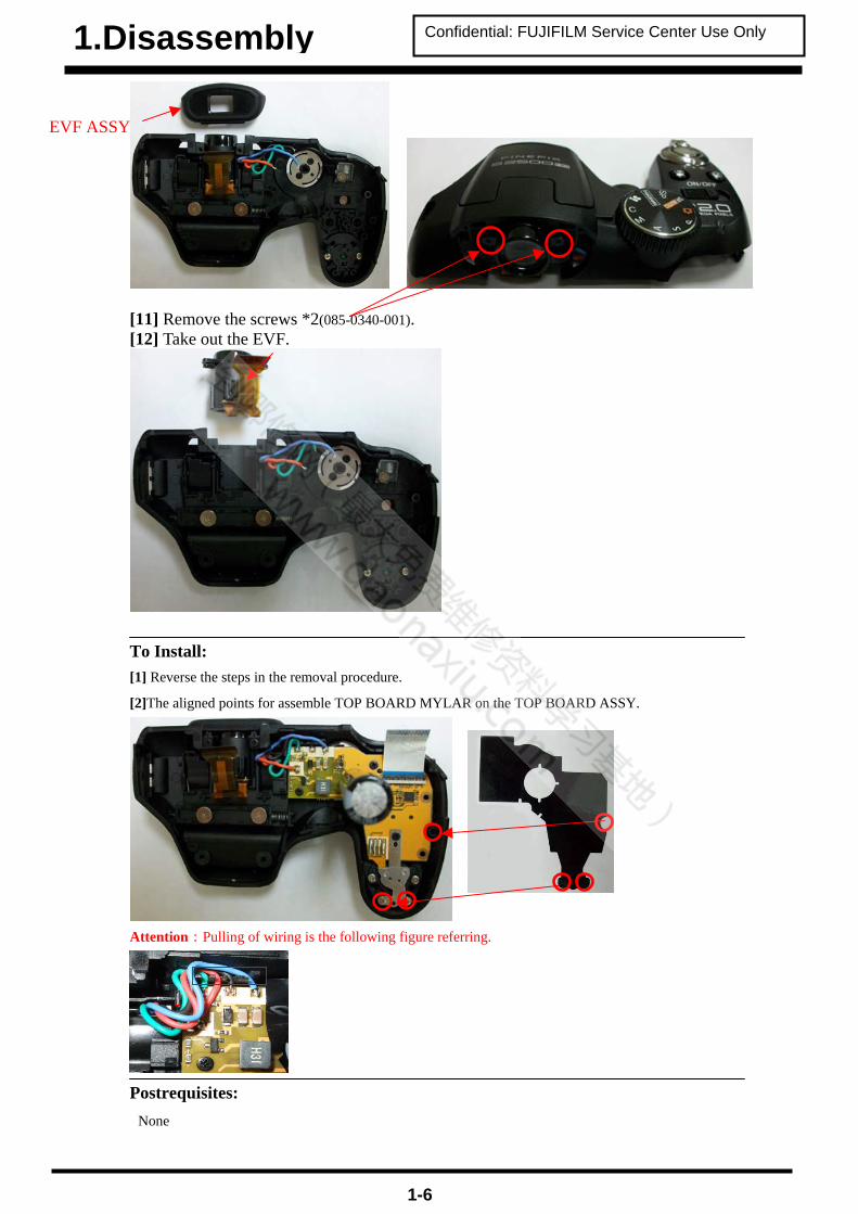
Confidential: FUJIFILM Service Center Use Only 1.Disassembly
EVF ASSY
[11] Remove the screws *2(085-0340-001). [12] Take out the EVF.
To Install: [1] Reverse the steps in the removal procedure.
[2]The aligned points for assemble TOP BOARD MYLAR on the TOP BOARD ASSY.
Attention:Pulling of wiring is the following figure referring.
Postrequisites: None
1-6

Confidential: FUJIFILM Service Center Use Only 1.Disassembly
FLASH TCOVER PI B & FLASH HINGE & FLASH BOTTOM ASSY & TOP COVER CONST: Prerequisites:
[1] Remove: • REAR COVER ASSY • BATTERY COVER ASSY • LCD HOLDER ASSY & LCD
To Remove: [1] Remove the screws *2(085-0340-001). [2] Take out the FLASH TCOVER PI B.
[3] Remove the FLASH HINGE. [4] Take out the FLASH BOTTOM ASSY.
[5] Take out the TOP COVER CONST.
To Install: [1] Reverse the steps in the removal procedure.
FLASH HINGE
Postrequisites:None
1-7
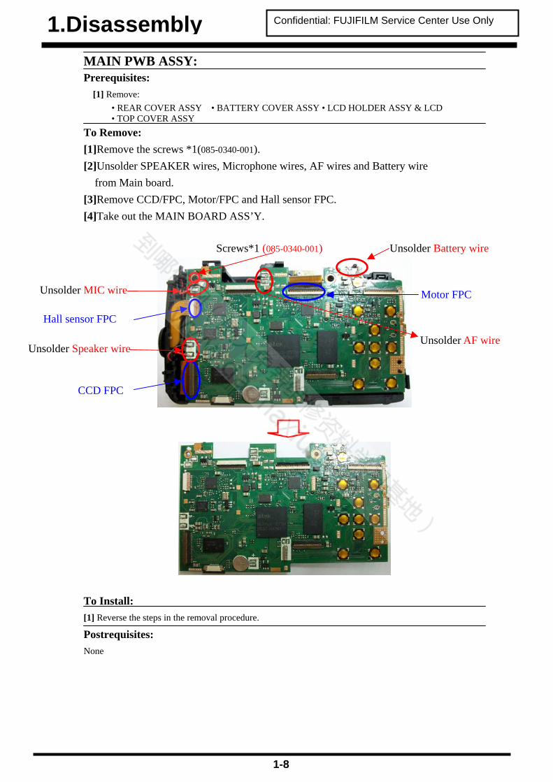
Confidential: FUJIFILM Service Center Use Only 1.Disassembly MAIN PWB ASSY: Prerequisites:
[1] Remove: • REAR COVER ASSY • BATTERY COVER ASSY • LCD HOLDER ASSY & LCD • TOP COVER ASSY
To Remove: [1]Remove the screws *1(085-0340-001). [2]Unsolder SPEAKER wires, Microphone wires, AF wires and Battery wire
from Main board. [3]Remove CCD/FPC, Motor/FPC and Hall sensor FPC. [4]Take out the MAIN BOARD ASS’Y.
To Install:
[1] Reverse the steps in the removal procedure.
Unsolder AF wire
CCD FPC
Hall sensor FPC
Motor FPC
Unsolder Battery wireScrews*1 (085-0340-001)
Unsolder Speaker wire
Unsolder MIC wire
Postrequisites: None
1-8

Confidential: FUJIFILM Service Center Use Only 1.Disassembly
PCBA AF LED ASSY: Prerequisites:
[1] Remove: • REAR COVER ASSY • BATTERY COVER ASSY • LCD HOLDER ASSY & LCD • TOP COVER ASSY
To Remove: [1] Remove screw*3 (085-0343-001). [2] Take out the PCBA AF LED ASSY.
To Install: [1] Reverse the steps in the removal procedure.
[2] Follow the grooves to assemble the wires of PCBA AF LED ASSY on Main Frame.
Postrequisites: None
1-9

Confidential: FUJIFILM Service Center Use Only 1.Disassembly LENS CONST:
Prerequisites: [1] Remove:
• REAR COVER ASSY • BATTERY COVER ASSY • LCD HOLDER ASSY & LCD • TOP COVER ASSY •MAIN PWB ASSY_1
To Remove: [1] Remove screw*4 (085-0341-001). [2] Take out the LENS CONST.
To Install: [1] Reverse the steps in the removal procedure.
Postrequisites: None
1-10

Confidential: FUJIFILM Service Center Use Only 1.Disassembly FRONT COVER ASSY B & FRAME ASSY & CAP MYLAR Prerequisites:
[1] Remove: • REAR COVER ASSY • BATTERY COVER ASSY • LCD HOLDER ASSY & LCD
• TOP COVER ASSY •MAIN PWB ASSY_1 • LENS CONST To Remove: [1] Remove the CAP MYLAR. [2] Remove the screw*5(085-0340-001). [3] Take out the FRAME ASSY, FRONT COVER ASSY B and MICROPHONE.
CAP MYLAR
Screws*5 (085-0340-001)
FRAME ASS’Y
FRONT COVER ASSY B SIDE DOOR is included in
FRAME ASSY
MICROPHON
1-11

Confidential: FUJIFILM Service Center Use Only 1.Disassembly To Install: [1] Reverse the steps in the removal procedure.
[2]The aligned points for assemble CAP MYLAR on the FRAME ASSY.
[3] Follow the grooves to assemble the wires of Microphone on Main Frame.
Postrequisites: None
1-12
Confidential: FUJIFILM Service Center Use Only 2.Scematics
2. Scematics 2-1. Cautions <Cautions when replacing parts>
• Do not reuse removed parts. Always use new parts. • Note that the negative side of tantalum condensers is readily damaged by heat. • Except for chemical condensers and tantalum condensers, voltage is not displayed on condensers with a voltage
resistance of 50V or less. • Resistors not marked are 1/16W chip resistors. • KΩ = 1000Ω, MΩ = 1000KΩ
Revised:05, Jan. 2010
2-1

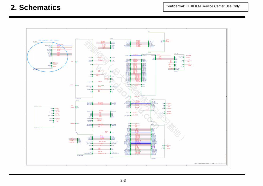
Confidential: FUJIFILM Service Center Use Only 2. Schematics
2-2
Confidential: FUJIFILM Service Center Use Only 2. Schematics
2-3

Confidential: FUJIFILM Service Center Use Only 2. Schematics
2-4

Confidential: FUJIFILM Service Center Use Only 2. Schematics
2-5

Confidential: FUJIFILM Service Center Use Only 3. Adjustments
3. Adjustments 3-1-1. The handling of image files in internal memory Image files contained in the internal memory should be handled as described below. <Procedure for handling images> When either of following work is necessary, as many as possible of the image files should be extracted from the camera's internal memory and then written into the internal memory in the repaired or replacement camera before the camera is returned to the customer. 1. When the replacement camera is provided. 2. If adjustment using the adjustment software is required.
--->To prevent accidental erasure, carry out this Step not only when the MAIN PWB ASSY is replaced but in all cases. *Note For PTP-connected cameras, carry out the procedure in "ii. Procedure for PTP-connected cameras and images that cannot be downloaded to a PC". <Image file transfer procedure> I. Procedure when images can be downloaded to a PC
* If a memory card is inserted, data in the internal memory cannot be backed up. (1) Back up the images stored in internal memory.
• Create a folder (named and located so as to avoid any confusion with the user's images). • Without inserting a memory card, connect the camera to a PC and copy the image files on the removable disk
recognized by the PC to the folder created in the previous Step . • Check that the images can be displayed correctly on the PC.
(2) Return the backed up image files from the PC to the camera. • Turn the camera on without a memory card inserted and format the camera's internal memory. • Without inserting a memory card, connect the camera to the PC and copy the image files from the folder containing
the images backed up in the previous Step onto the removable disk recognized by the PC. • Check that the images can be displayed correctly on the camera. • Delete the backup files created on the PC in Step (1) (the user's image files).
II. Procedure when images cannot be downloaded to a PC
(1) Back up the images stored in internal memory. • Insert a memory card to be used for image backup into the camera and format the card. • From the SETUP menu, reset the frame numbers. • Select image copying from the playback menu, select "Camera -> Card" for all the frames and then copy the images. • Check that the images can be displayed correctly on the camera.
(2) Return the backed up image files from the memory card to the camera. • Before inserting the card, format the camera's internal memory. • Insert the memory card containing the backed up copies of the user's image files. • From the SETUP menu, reset the frame numbers. • Select image copying from the playback menu, select "Card -> Camera" for all the frames and then copy the images. • Remove the memory card and check that the images can be displayed correctly on the camera. • From the SETUP menu, set the frame numbers to the default sequence. • If the image file numbers have changed, always notify the user in writing that the image file numbers have changed.
III. Procedure for PTP-connected cameras and images that cannot be downloaded to a PC
(Images can only be backed up to a PC. * Normally, back up images using procedure II.) (1) Back up the images stored in the camera's built-in memory.
• Create a folder (named and located so as to avoid any confusion with the user's images). • Without inserting a memory card, connect the camera to the PC and check the image files in the camera on the PC.
Then copy those files to the folder described on the previous page. • Check that the images can be viewed successfully on the PC.
(2) Return the backup image files from the PC to the camera.
• With no memory card inserted, turn the camera on and format the built-in memory. • Using a card reader or similar device, check the memory card to be used for image file backup on your PC. • Copy the image files from the image file backup folder on the previous page into the "DCIM¥100_FUJI¥" folder on the
image file backup memory card. • Using a safe procedure, remove the image file backup memory card from your PC. • Load the image file backup memory card into the camera. • Select "Copy image" in the Playback menu, select all the frames in "Card -> Camera" and then copy the images. • Remove the memory card and check that the images can be viewed successfully. • Delete the backup files (user image files) created on the PC in Step (1).
Revised:31, Mar. 2010
Revised:05, Jan. 2010
3-1

Confidential: FUJIFILM Service Center Use Only 3. Adjustments
3-1-2. Adjustment when replacing major parts
Note that the adjustment data will be erased if the adjustment sequence is not followed correctly.
No.
Replacing
parts
MAIN PWB ASSY LENS CONST LCD
0 LCD Adjustment 1 Firmware Download * 2 Module Select 3 EFA Adjustment 4 Shutter Delay Adjustment 5 ISO DBP Shading Adjustment 6 RunIn WBP Adjustment 7 OIS DATA Download 8 USB ID/LENS DATA Writing 9 OIS Calibration 10 Destination Setting
* Always download the firmware after completing the adjustments and replace the adjustment firmware with the project firmware.
3-2. Measuring instruments used Measuring equipment Remarks
PC Used for USB ID/LENS DATA Write and operation checks (PC-AT
compatible)OS: Win XP, SP2
Brightness meter LS-110 (Minolta) or equivalentColor temperature meter Color Meter IIIF (Minolta) or equivalentPattern box PTB450F
3-2

Confidential: FUJIFILM Service Center Use Only 3. Adjustments
3-3. Use jig list Parts. No Name Comment Remarks ZJ01733-101 FxS1700 W PC Soft Ver.2.00 General adjustment Windows 2000/XP J OS New jig *
For the S1800/S1850/S1880/S1900ZJ01732-101 FxS1700 Firmware Ver.2.00 Firmware Download New jig * For the
S1800/S1850/S1880/S1900ZJ01734-100 FxS1700 USB ID/LENS DATA Writing Software USB_ID/LENS DATA Writing
New jig * For the S1800/S1850/S1880/S1900
ZJ01735-100 FxS1700 OIS Calibration Software OIS Calibration New jig * For the S1800/S1850/S1880/S1900
ZPU0512-100 SD CARD ULTRA 1GB General adjustment ZJ00611-100 X-Y stage for AF adjustment General adjustment Common with the FinePix M603 ZJ00653-100 LB140 filter holder kit for X-Y stage General adjustment Common with the FinePix F700 ZJ00553-100 AF solid chart General adjustment Common with the FinePix S2Pro ZJ00008-100 Lens holder EFA Adjustment Common with the FinePix M603 ZJ00009-100 Stand EFA Adjustment Common with the FinePix M603 ZJ00251-100 Siemense star chart EFA Adjustment Common with the MX500 ZJ00007-100 Conversion lens (f=600mm) EFA Adjustment Common with the MX500
ZJ00006-100
LB140 filter
ISO_DBP_Shading Adjustment
Common with the DS-30/DS-20/DS-7 DS-30/DS-20/DS-7
056-0166-001
USB cable
USB_ID/LENS DATA Writing
This is bundled to the product
ZJ01728-100 N SCREW DRIVER General repair ZJ00581-100 Discharger Discharger for FLASH UNIT
ZJ01108-100
Vibration generator
OIS Calibration
Common with the FinePix F50fd (Eccentricaxis type A: With ZJ01122-100 as set) Separate AC cable
ZJ01107-100 S1700ADP for Vibration gen OIS Calibration New jig
ZJ01119-100 Filter holder OIS Calibration Common with the FinePix F50fd ZJ01118-100 45 degree adaptor OIS Calibration Common with the FinePix F50fd ZJ01148-100 Eccentric axis type C (0.2) OIS Calibration Common with the FinePix S100FS
ZJ01123-100
ND Filter 75mm size Concentration 0.5
OIS Calibration * Will be provided as required.
Common with the FinePix F50fd
ZJ01124-100
ND Filter 75mm size Concentration 1.0
OIS Calibration * Will be provided as required.
Common with the FinePix F50fd
ZJ01125-100
ND Filter 75mm size Concentration 1.5
OIS Calibration * Will be provided as required.
Common with the FinePix F50fd
ZJ01126-100
ND Filter 75mm size Concentration 2.0
OIS Calibration * Will be provided as required.
Common with the FinePix F50fd
CR0130900U9
DC COUPLER CP-04
General adjustment
Commom with the FinePix S1000fd
ZJ01113-100 LED Chart (IS) OIS Calibration Common with the FinePix F50fd
ZJ01134-100
QR Code reader
USB_ID/LENS DATA Writing Common with the FinePix S8000fd
* In the future, if upgraded versions of the firmware are released, use the most recent version.
Please downloaded from Web server (https://denhin.fujifilm.co.jp/csg_en/index.htm or http://fujifilm-di.intranets.com/).
3-3

Confidential: FUJIFILM Service Center Use Only 3. Adjustments
3-4. Calibration method of pattern box <Use the pattern box for Camera adjustment>
Turn on the power supply in the pattern box.
Afterwards, wait for about ten minutes so that the source of
light may stabilize.
(1) Brightness
160 ± 5 cd/m2 (with LB140 filter)
No chart, center of pattern box
Minolta brightness meter LS-110 or equivalent
* Calibration method
Place the filter (LB140) against the pattern box. With
the filter (LB140) in contact with the brightness meter,
adjust the pattern box brightness to 160 ± 5 cd/m2.
(2) Color temperature
6100 ± 50 K (with LB140 filter)
No chart, center of pattern box
Minolta color meter IIIF or equivalent
* Calibration method
Place the filter (LB140) against the pattern box. With the filter (LB140) in contact with the color temperature meter, adjust
the pattern box color temperature to 6100 ± 50 K.
3-4

Confidential: FUJIFILM Service Center Use Only 3. Adjustments
3-5. Preparation of Adjustment Software
3-5-1. Various downloading software decompressions, preservation methods, and notes
The PC adjustment softwares are in a specified Web server,
FinePix S1700 W PC Soft Ver2.00 ZJ01733-101..Zip
and both of these are the compression of ZIP form files.
Therefore, after downloading these compression files from
the Web server, the decompression of the file is necessary.
In the decompression software, if the decompression of the
ZIP form can be done, any software is OK.
(Please prepare each one for the decompression software.)
The decompression and the preservation method of the PC
adjustment software and the firmware are described
to the following.
* The adjustment soft decompression and set up the
adjustment card.
<Screen> <Step 1>
The adjustment software is downloaded from WEB, and
software is installed in the PC.
We have uploaded the " ZJ01733-101.Zip" on our website:
(https://denhin.fujifilm.co.jp/csg_en/index.htm).
ZJ01733-101
<Step 2>
" ZJ01733-101.Zip " is a compression of "ZIP type" file
<Step 3>
Copy the "menu" file and "Firmware" folder in the
"ZJ01733-101" folder to a formatted SD card.
3-5

Confidential: FUJIFILM Service Center Use Only 3. Adjustments
3-5-2. Composition of Adjustment Software, and Creation of SD Card for Adjustment In order to perform adjustment, an SD card for each adjustment item must be created.
<Step 1>
Copy the "Batch" folder (Fig. 3-5-4) of the folder for each item to be adjusted, and specified files directly under the SD card,
following the instructions given for each item to be adjusted (Fig. 3-5-5).
* When a "Batch" folder already exists directly under SD card, delete this folder before copying.
* When it is not clear anymore which "Batch" folder is directly under SD card, redo the procedure starting with this step.
FX S1700_W
3-5-3. Creating a firmware SD card
<Fig.3-5-4>
In order to perform Firmware Download, it is necessary to create a firmware SD card.
<Step 1>
Downloadcompressed Firmware (ZJ01732-***.zip) from Web server (https://denhin. fujifilm.co.jp/csg_en/index.htm).
<Step 2>
Decompression the downloaded compression file (Fig. 3-5-6).
<Step 3>
Copy the "TBM_L145.BIN" file and the "HiddenMenu" folder, which are stored in the extracted "FxS1700 Firmware Ver.*.** "
folder, under SD card (Fig. 3-5-7).
* When a "Batch" folder already exists directly under SD card, delete this folder.
TBM_L145.BIN FxS1700 Firmware Ver.*** ZJ01732-***
TBM_L145.BIN
3-6

Confidential: FUJIFILM Service Center Use Only 3. Adjustments
3-5-4. Creating a LCD Adjustment SD card In order to perform LCD Adjustment, it is necessary to create a LCD Adjustment SD card.
[Note]
• Please use the software properly according to the LCD manufacturer.
<Confirm method>
Judge the manufacturer with the stamp in the LCD frame.
LCD Frame Manufacturer Use software
GIANTPLUS GPT LCDTypeSelect_GPT 3.0
WINTEK WINTEK LCDTypeSelect_WINTEK3.0
<Step 1>
Download compressed Adjustment software of LCD from Web server (https://denhin.fujifilm.co.jp/csg_en/index.htm)
(Figure : for WINTEK).
<Step 2>
" Fx S1700 W PC SOFT Ver.2.00" is opened. (Fig. 3-5-8).
<Step 3>
Copy the "Batch" folder stored in LCDTypeSelect_WINTEK 3.0 folder directly under the SD card (Fig. 3-5-9).
* When a "Batch" folder already exists directly under SD card, delete this folder before copying.
FX S1700_W 3.0
3-7

Confidential: FUJIFILM Service Center Use Only 3. Adjustments
3-6. LCD Adjustment [Note]
• Do not turn the camera off until the LCD Adjustment is completed.
<Step 1>
Insert the LCD Adjustment SD card into the camera.
<Step 2>
Connect the DC COUPLER CP-04 to the camera.
<Step 3>
Set the camera's power switch to "ON"
[Note] Cancel when the date setting screen appears.
<Step 4>
The adjustment starts by the automatic operation, and the power supply cuts. Remove the LCD Adjustment SD card.
-->LCD Adjustment ends.
3-8

Confidential: FUJIFILM Service Center Use Only 3. Adjustments
3-7. Firmware Download [Note]
• Always download the latest version of the firmware.
• Do not turn the camera off until the Module Select is completed.
<Settings for Firmware Download >
DC COUPLER CP-04 <Step 1>
Insert the firmware SD card into the camera.
<Step 2>
Connect the DC COUPLER CP-04 to the camera.
<Step 3>
Set the camera's power switch to "ON"
[Note] Cancel when the date setting screen appears.
<Step 4>
Press the MENU/OK button to select "SET-UP" and then press the MENU/OK button.
<Step 5>
Select "RESET" and press the MENU/OK button.
3-9

Confidential: FUJIFILM Service Center Use Only 3. Adjustments
<Step 6>
The "RESET OK?" screen is displayed. Press the T button
and the left arrow key at the same time.
<Step 7>
Select "NAND TOOL" and press the MENU/OK button.
<Step 8>
Select "B1.Update Main Code: TBM_X." and press the
MENU/OK button.
--> Firmware upgrade starts.
3-10

Confidential: FUJIFILM Service Center Use Only 3. Adjustments
<Step 9>
If the "Result: Success(0) !" screen appears, turn the camera off.
<Step10>
Repeat from <Step 3> to <Step 6>, and select "FIRMWARE
VERSION".
--> The version information is displayed.
3-11

Confidential: FUJIFILM Service Center Use Only 3. Adjustments
3-8. Module Select [Note]
• Do not turn the camera off until the Module Select is completed.
<Settings for Module Select >
It's same as 3-7 Firmware Download.
<Step1>
Set the camera's power switch to "ON"
[Note] The SD card used by "3-7 Firmware Download " isn't removed and it's put into effect.
<Step2>
"3-7 Firmware Download " It's same as <STEP 4> empty <STEP 6>.
<Step 3>
Select "MODULE SELECT" and press the MENU/OK button.
<Step 4>
Following table is seen, MODULE is chosen and MENU/OK button is pushed.
MODULE SELECT Model name
L140 FinePix S1800/S1850/S1880/S1900
L140C FinePix S1600/S1700/S1730/S1770
L145 FinePix S2500HD/S2600HD/S2700HD
L146 FinePix S2550HD
3-12

Confidential: FUJIFILM Service Center Use Only 3. Adjustments
3-9. EFA Adjustment <Settings for EFA Adjustment>
(1) Set up the Siemens star chart and conversion lens so that they are 600 ± 5 mm apart. (2) Position the chart so that the brightness of the chart surface is between 1000 ~ 200 LUX.
5 mm to 10 mm with the zoom set to TELE. Note that the camera lens should not touch the conversion lens.
<Step 1> Copy the "Batch" folder of the "EFA" folder, which is stored in the FxS1700_W folder, directly under SD card. * When a "Batch" folder already exists directly under SD card, delete this folder before copying. Insert the adjustment SD card and the DC COUPLER CP-04 into the camera, and turn power ON. --> Adjustment software activates. [Note] ・ Use a fully charged battery. ・ Cancel when the date setting screen appears. <Step 2> If the "EFA OK!" screen appears, turn the camera off.
--> EFA Adjustment ends.
3-13

Confidential: FUJIFILM Service Center Use Only 3. Adjustments
3-10. Shutter Delay Adjustment [Note]
• Darken the surroundings during calibration (a darkroom environment is ideal). • Calibrate the pattern box before the adjustment. • Any soiling on the pattern box dispersion plate or reflective plate will result in unevenness in the lighting and cause errors during adjustment. Take care to carry out periodic pattern box cleaning and testing.
<Settings for Shutter Delay Adjustment>
Within 5 mm from the lens face
with the TELE position
<Step 1> Copy the "Batch" folder of the "Shutter Delay" folder, which is stored in the FxS1700_W folder, directly under SD card. * When a "Batch" folder already exists directly under SD card, delete this folder before copying. Insert the adjustment SD card and Connect the DC COUPLER CP-04 to the camera.and turn power ON. --> Adjustment software activates. [Note] Cancel when the date setting screen appears. <Step 2> If the "Shutter Calibration ok" screen appears, turn the camera off.
Shutter Delay Adjustment ends.
3-14

Confidential: FUJIFILM Service Center Use Only 3. Adjustments
3-11. ISO_DBP_Shading Adjustment [Note] • Perform Shutter Delay Adjustment before performing this step.
<Settings for ISO_DBP_Shading Adjustment>
Within 5 mm from the lens face with the TELE position
<Step 1> Copy the following items directly under SD card; the files, "Big_Lamp_l145.fig", "Small_Lamp_L145_1.fig", "ISO_Flash_L145.txt" and "ISO_Result_L145.txt", “ISO_Report_L145.txt”,” Note.txt”and the "Batch" folder, all of which are stored in the"ISO_DBP_Shading" folder inside the FxS1700_W folder. * When a "Batch" folder already exists directly under SD card, delete this folder before copying. Insert the adjustment SD card and the DC COUPLER CP-04 into the camera, and turn power ON. --> Adjustment software activates. [Note] • Cancel when the date setting screen appears.
<Step 2>
Select "Factory Small Lamp" and press the OK button.
3-15

Confidential: FUJIFILM Service Center Use Only 3. Adjustments
<Step 3> Select " SmallLampNo:1 " and press the OK button.
The message "Shading Verify OK!!" will be displayed
approximately 4 minutes later. When screen returns to ISO Big/Small/Factory Mode, turn power OFF.
ISO_DBP_Shading Adjustment ends.
3-16

Confidential: FUJIFILM Service Center Use Only 3. Adjustments
3-12. RunIn_WBP Adjustment [Note] • Darken the surroundings during calibration (a darkroom environment is ideal). Alternatively, prepare a box that is painted black on the inside and perform the adjustments with the camera enclosed in the box. <Step 1> Copy the "Batch" folder of the "RunIn_WBP" folder, which is stored in the FinePixS1700 folder, directly under SD card. * When a "Batch" folder already exists directly under SD card, delete this folder before copying. Insert the adjustment SD card and the DC COUPLER CP-04 into the camera, and turn power ON. --> Adjustment software activates. [Note]• Cancel when the date setting screen appears. <Step 2> When the "Press OK Key to leave" screen is displayed, press the OK button and then turn power OFF. RunIn_WBP Adjustment ends.
3-17

Confidential: FUJIFILM Service Center Use Only 3. Adjustments
3-13 OIS DATA Download
<STEP1> Copy the "Batch" folder and “OISFW.srt” of the "OIS _FW" folder, which is stored in the FxS1700_W folder, directly under SD
card. * When a "Batch" folder already exists directly under SD card, delete this folder before copying. Insert the adjustment SD card and the DC COUPLER CP-04 into the camera, and turn power ON. --> Adjustment software activates. [Note]• Cancel when the date setting screen appears. <STEP2> If the "DL OKOKOKOK ^_^“ screen appears, turn the camera off. SD card is removed. -->OIS Data download end.
3-18

Confidential: FUJIFILM Service Center Use Only 3. Adjustments
3-14. Preparation of FxS1700 USB ID/LENS DATA Writing Software
<Step 1>
The adjustment software is downloaded from WEB, and ZJ01734-100..Zip Fx S1700 USB ID/LENS DATA Writing Software software is installed in the PC.
We have uploaded the "ZJ01734-100.zip" on our website:
(https://denhin.fujifilm.co.jp/csg_en/index.htm).
<Step 2>
7
ZJ01734-100 7
Decompression the downloaded compression file.
<Step 3>
Copy the two folders, "Vista for Service FF 4.1.2.7", and
"Upgrade inf file", which are stored in the extracted
"ZJ01734-100" folder, to C drive.
3-19

Confidential: FUJIFILM Service Center Use Only 3. Adjustments
<Step 4>
Double-click [Setup.exe], which is stored in the "Vista for Service FF 4.1.2.7" folder.
<Step 5>
When the window shown below appears, click the "Next" button.
<Step 6>
When the window shown below appears, click the "Next" button.
3-20

Confidential: FUJIFILM Service Center Use Only 3. Adjustments
[Note] Click the "Yes" button when the following image is displayed.
<Step 7>
Double-click [AInf.exe], which is stored in the "Upgrade inf file" folder.
<Step 8>
When the window shown below appears, click the "Browse" button.
3-21

Confidential: FUJIFILM Service Center Use Only 3. Adjustments
<Step 9>
The following image is displayed. Select "FUJI_A215.inf" and click the "Open" button.
<Step 10>
The following image is displayed. Click the "Copy source INF file to Windows INF's directory" button.
When the "Success" screen is displayed, click "Exit".
<Step 11>
Overwrite the copy of [Model.ini] in "C:¥Program Files¥Altek Corp¥Vista for Service" with [Model.ini] stored in the "Upgrade inf
file" folder.
3-22

Confidential: FUJIFILM Service Center Use Only 3. Adjustments
3-15 LENS DATA Read Perform this step before assembling the camera (with the lens unit removed). <STEP1> (1) Connect the QR code reader to the USB port on the PC. (2) Make a txt file and make the save file of the qr cord (3) Scan the QR code with the QR code reader
<STEP2>
Copy QR cord data in a txt file and save it by the serial number name of the camera
*Use LENS DATA which I stored for "LENS DATA_Writing"
3-23

Confidential: FUJIFILM Service Center Use Only 3. Adjustments
3-16. USB_ID/LENS DATA Writing 3-16-1USB_IDWriting
<Step 1>
Connect the DC COUPLER CP-04 and USB cable to the camera, and turn the power switch ON while pressing the T button
and the right arrow key.
[Note] An indication picture of LCD becomes blue.
<Step 2>
Double-click [Vista.exe] in C: ¥Program Files¥Altek Corp¥Vista
for Service.
<Step 3>
When the screen shown on the right appears, click the
"Write" button.
<Step 4>
The image on the right is displayed. Select camera model.
3-24

Confidential: FUJIFILM Service Center Use Only 3. Adjustments
<Step 5>
Input the camera's serial number for Product Serial, and click
the "Write" button.
<Step 6>
Click the "OK" button.
<Step 7>
Turn the camera off.
USB_ID Writing ends.
3-25

Confidential: FUJIFILM Service Center Use Only 3. Adjustments
3-16-2 LENS DATA_Writing <STEP1>
Choose the thing that a txt file name accords with a cereal of the repair object product and open LENS DATA which I stored to a
PC beforehand
<STEP2>
Copy LENS DATA in the Txt file and
stick it on "USB ID/LENS DATA Writing Soft". I click a Write button.
PD98210202642468E92C803A24
<STEP3>
If chart below indication is given to LCD and the PC, I click the OK button. The power supply of the camera is automatic and
becomes OFF. LCD PC
USB_ID Writing ends.
3-26

Confidential: FUJIFILM Service Center Use Only 3. Adjustments
3-17. OIS Calibration 3-17-1. OIS Test <STEP1>
Copy the "Batch" folder of the " OIS_Test " folder, which is stored in the FxS1700_W folder, directly under SD card. * When a "Batch" folder already exists directly under SD card, delete this folder before copying. Insert the adjustment SD card and the DC COUPLER CP-04 into the camera, and turn power ON. --> Adjustment software activates. Condition: Put the camera on a stable table or ground. (Don't touch or shake the camera or table when testing.)
<STEP2>
Put the camera on the desk, and power on the camera.
(When testing, don’t touch the camera or desk.)
Camera will do “Hall Bias / Hall Gain”, “Gyro Bias” and “Abnormal Oscillation” calibration automatically. When LCD displays “Test ok”, the OIS calibration was done. Press “POWER” button to de-energize the CAMERA.
<Settings for OIS Calibration >
3-27

3. Adjustments Confidential: FUJIFILM Service Center Use Only
S1700 ADP for Vibration generator adapter usage To Remove:
[1] Remove the screws of the stopper back side *4
[2] Unscrew the clamp and adjust it so that a stopper comes to the center of EVF.
[3] Set a camera and turn a screw to the position where a clamp is fixed
Before After
3-28

Confidential: FUJIFILM Service Center Use Only 3. Adjustments
Calibration Software installation
Various downloading software decompressions, preservation methods, and notes The PC adjustment softwares are in a specified Web server, and both of these are the compression of ZIP form files. Therefore, after downloading these compression files from the Web server, the decompression of the file is necessary. In the decompression software, if the decompression of the ZIP form can be done, any software is OK. (Please prepare each one for the decompression software.) The decompression and the preservation method of the PC adjustment software and the firmware are described to the following. The PC adjustment soft decompression and preservation method
FxS1700 OIS Calibration Software ZJ01735-100zip
<Step1> The adjustment software is downloaded from WEB, and software is installed in the PC. We have uploaded the “OIS Calibration Software(ZJ01735-100.zip)” for “FxS1700” on our website: (https://denhin.fujifilm.co.jp/csg_en/index.htm).
3-29

Confidential: FUJIFILM Service Center Use Only 3. Adjustments
3-17-2. Gyro calibration “ZJ01735-100” is a compression of “ZIP type” file. The “Fxs1700 OIS Calibraion Software” folder can be done by extracting it by “Compression software”. Copy the “Fxs1700 OIS Calibraion Software” folder to the “C” drive on the Adjustment PC.
FxS1700 OIS Cali 7
<STEP1> Execute the software of OISGyroCali.exe
<STEP2>
Press “Config” button to set Image Save Direction. (You can double-check the images which generated by calibration.)
3-30

Confidential: FUJIFILM Service Center Use Only 3. Adjustments
<STEP3>
Set a camera at Vibration generator Connect the camera to PC via USB cable. (LCD shows blue screen) Press “Tele” + “Power” button to power on the camera to enter Vista mode.
<STEP 4> Press item1, and camera will take a picture automatically. When the button of item3 is enabled, power on the Vibrator and press item3 to execute the calibration. PC will control the camera to do the calibration automatically.
*When the environment is light, please use" ND Filter".
<STEP 5>
On the software of a PC, "OIS Calibration Test OK!!, ", and, if indication goes out, I turn off a camera.
3-31

Confidential: FUJIFILM Service Center Use Only 3. Adjustments
3-18. Destination Setting
[Note]
• Do not turn the camera off until the Destination Setting is completed.
<Step 1>
Look at the 3rd digit from the left in the camera's serial number , and then copy the "Batch" folder of the corresponding
"Reset_*" folder, directly under SD card. Folder Destination 3rd digit in serial no. Reset_JP JP-model 0 to 8 Reset_US US-model A to H,J,K Reset_E EF/E1/EG/EE-model L to N,P to V Reset_CH CH-model W to Z
* When a "Batch" folder already exists directly under SD card, delete this folder before copying.
Insert the DC COUPLER CP-04 and the adjustment SD card into the camera, and turn power ON.
--> Adjustment software activates.
[Note] Cancel when the date setting screen appears.
<Step 2>
The adjustment starts by the automatic operation, and the power supply cuts.
--> Destination Setting ends.
3-32

Confidential: FUJIFILM Service Center Use Only 4. Inspection
4. Inspection
4-1. Required Measuring Equipment Parts number Measuring equipment Remarks Power supply AC adapter (AC-5V), Regulated power supply Digital voltmeter For general use Ammeter For general use (able to measure 1mA or less) TV Monitor TV monitor, minimum resolution 600 lines PC Windows XP USB Cable This is bundled to the product AV Cable This is bundled to the product CR0130900U9 DC COUPLER CP-04 Common with adjustment JIG ZJ00580-100 POWER CABLE JIG Common with adjustment JIG ZJ00525-100 Macro Chart Resolution confirmation ZJ00885-100 LCD Inspection Data For LCD inspection (downloaded from WEB.) ZJ01021-100 Face Detection Test Chart Checking face detection operation ZPU0512-100 SD CARD ULTRA2 1GB To check SD card recording
4-2. Connection of Measuring Equipment Use DC COUPLER CP-04 and POWER CABLE JIG.
The output current of the Regulated power supply must not become 2.5A or more.
Revised:05, Jan. 2010
4-1

Confidential: FUJIFILM Service Center Use Only 4. Inspection
4-3. Inspection and Factory Settings Seq
. Item Mode Preparations for adjustment (measurement points, subject, other)
Method of adjustment (VRs, waveforms, required values)
Measuring equip. and jigs
1 External visual check
(1) Observe the camera. (1) Check for damage to the outer casing. (2) Check for problems with the clicking or sliding movement of switches. (3) Check for dust or fogging in the LCD.
2 Power switch check
Auto mode (1) Plug the DC COUPLER into the camera and connect the AC-5V. (2) Insert a SD card and close the card cover. (3) Turn the camera on. (4) If a message prompting the user to set the date appears, press the button specified on the right. (5) Check the LCD screen display status. (6) Check for blemishes in the CCD live image.
(2) SD card for recording checking. (3) Check that the camera beeps. (4) <DISP/BACK> (5) Check that the live image and text is displayed. (6) Monitor a very bright subject and check that the live image does not dim or darken.
CR0130900U9
3 Zoom operation check
Auto mode (1) Zoom drive noise. (2) LCD screen. (3) Zoom operation (T <-> W).
(1) Check that there is no abnormal noise. (2) Check that there is no edge blurring Check that the screen display accurately tracks zooming. (3) Check that the zoom moves smoothly.
4 Shock noise check in Auto mode
Auto mode (1) Apply a shock to the camera using the shock jig.
(1) Check for problems on the LCD monitor. (2) Check that the camera recovers from synchronicity disruption. (Note) Do not apply shocks directly to the lens or card cover.
5 Resolution check Focusing check
Auto mode (1) Use a macro resolution chart as the subject. (2) Set the camera to Macro mode. (3) Set the flash mode to Flash OFF. (4) Set-up the camera so the chart center of the screen.(Distance:10cm) (5) Press the shutter button to take a picture.
(2) Press the 4-way button (left) and check that the Macro icon (tulip) appears on the LCD monitor. (3) Press the 4-way button (right) and check that the Suppressed Flash icon appears on theLCD monitor. (5) The indicator lamp lights green -> Intermittently lights red(recording) -> Turns off.
ZJ00525-100
6 Checking face detection operation
Auto mode (1) Set Face Detection to “ON”. (2) Set up the camera facing the face detection chart at a distance of 30 to 40 cm. (3) Press the S1 button.
(2) Check that the Face Detection icon is displayed on the LCD. (3) Check that the focusing target is aligned with a face that has the Face Detection icon.
ZJ01021-100
4-2

Confidential: FUJIFILM Service Center Use Only 4. Inspection
Seq. Item Mode Preparations for adjustment
(measurement points, subject, other) Method of adjustment
(VRs, waveforms, required values) Measuring
equip. and jigs 7 Flash
operation check
Auto mode (1) Set the flash mode to Forced Flash. (2) Focus on any subject and press the shutter button to take a picture.
(1) Press the 4-way button (right) and check that the Forced Flash icon appears on the LCD monitor. (2) The flash emits light. The indicator lamp lights green -> Intermittently lights red(recording) -> Turns off.
ZPU0512-100
8 Movie/audio recording check
Movie mode (1) Set the camera to Movie mode. (2) Press S1 -> S2 and then release S2 -> S1. (3) After 5 seconds, press and then release S1.
(1) Check that “STANDBY” appears on the LCD monitor. (2) Check that movie/audio recording begins. Check that “REC” appears on the LCD monitor. (3) Check that movie/audio recording ends and that the data is recorded on the card.
9 Movie/audio playback check
Playback (1) Set the camera to Playback mode. (2) Press the 4-way button (down) to play back the movie.
(2) Check that the movie is played back on the LCD monitor. Check that the sound is played back through the speaker.
10 Playback check
Playback (1) Plug the AV cable into the camera. (2) Check images shot at macro resolutions (manual photography). (3) Turn the camera off. The AV cable is pulled out from the camera.
(1) The LCD image disappears and the indicator lamp lights green. (2) Where the horizontal resolution is as follows: 350 TV lines or better at the center and 300 TV lines or better at the periphery (NTSC). 300 TV lines or better at the center and 250 TV lines or better at the periphery (PAL).
AV cable TV monitor
11 Playback mode check
Playback (1) Start up in playback mode. (2) If a message prompting the user to set the date appears, press the button specified on the right. (3) Check the playback image.
(1) Press the <Playback> button. (2) <DISP/BACK> (3)Check that the last image shot appears, regardless of whether it is automatic or manual. Check that the date is displayed in the YYYY.MM.DD format.
12 PC connection checking
Auto mode (1) Connect the camera to the PC with the USB cable. (2) Copy the image files in the camera to a folder on the PC. (3) Disconnect the USB cable from the camera.
(1) Check that the PC recognizes the camera over a PTP connection. (2) Check that the image files have been copied to the PC.
USB cable PC
13 Erase mode check
Erase (1) Select “Erase” -> “Erase all” from the menu and then press the “OK” button. (2) Press the “OK” button again. (3) Turn the camera off. Disconnect the SD card from the camera.
(1) Check that an erase message such as the following appears: Japan: “ 全コマ消去 OK?” Overseas:“ERASE ALL OK?” China: “ OK?” (2) Check that the recorded images are erased.
4-3

Confidential: FUJIFILM Service Center Use Only 4. Inspection
Seq. Item Mode Preparations for adjustment
(measurement points, subject, other) Method of adjustment
(VRs, waveforms, required values) Measuring
equip. and jigs 14 LCD
dust/defect check
Playback (1) Insert a LCD INSPECTION SD card. (2) Play back a completely black image. (3) Play back a completely white (75%) image.
(2) Check that there are no noticeable dust flecks or stains (bright spots, smears, flashing points, etc.) on the screen.
ZJ00885-100
15 Battery low check
Movie (1) Plug the DC COUPLER into the camera and connect the POWER CABLE JIG. (2) Set the power supply voltage. (3) Turn the camera on. (4) Set the camera Movie mode. (5) Set the end voltage.
(2) 5.00 V ± 0.05 V (3) Check that the camera start up normally. (5) 4.33 V ± 0.10 V Check that the zoom retracts and the camera turns off after the battery low warning (end) appears.
ZJ00580-100 CR0130900U9
16 Current consumption check
Auto mode (1) Plug the DC COUPLER into the camera and connect the POWER CABLE JIG. (2) Set the power supply voltage. (3) Turn the camera on. (4) Set the Mode to AUTO mode. (5) After the LCD live image appears, check the current consumption. (6) Check that the flash is set to Forced flash mode. (7) Set the flash mode to AUTO.
(2) 5.00 V ± 0.05 V (5) 500 mA or less (6) Backup check.
ZJ00580-100 CR0130900U9
17 Leakage current
OFF (1) Plug the DC COUPLER into the camera and connect the POWER CABLE JIG. (2) Set the power supply voltage. (3) Check the standby current when the power is turned off.
(2) 5.00 V (3) 0.5 mA or less
ZJ00580-100 CR0130900U9
18 Shipping inspection
(1) Mode. (2) SETUP frame no. (3) Battery and cards not inserted. (4) Internal memory. (5) Battery cover. (6) Check that the lens retracts and that the lens barrier are closed. (7) Power off.
(1) AUTO mode (2) New: The default SETUP frame No. setting is “Continuous”, but to clear the number of frames in the frame number memory to zero, you should always change the setting to “New” before turning the camera off. (3) Normal (4) Check that the internal memory is formatted. *Excluding customers camera. (5) Closed (7) The power supply is stopped after the camera's shutdown sequence ends.
4-4

5-1. Packing and Accessories 5-1-1. FinePix S1800 E1-model
Ref NO. Parts No. Deseription CommentA101 082-0892-001 UNITARY BOX S1800 WA102 082-0901-001 TRAYA103 083-0075-001 PLASTIC BAG 250X155A104 083-0523-001 PLASTIC BAG 150X200A105 088-2811-001 PRODUCT LABEL S1800 EUA106 056-0198-001 USB CABLE 3 INA107 080-0047-001 STRAP SHOULDERA108 054-0027-001 ALKALINE BATTERYA109 002-CY52-000 LENS CAP ASSYA110 088-2483-001 BAR CODE LABEL EUA111 088-2478-001 CERITIFICATION SEALA112 082-0900-001 GIFTBOX PADA113 301-6139-001 WWN PRINT
A113 301-6151-001 WWN PRINTA114 301-2137-001 WARRANTY EA115 301-0115-001 BASIC MANUAL FRA116 301-0116-001 BASIC MANUAL DEA117 301-0118-001 BASIC MANUAL NLA118 332-0187-001 L140MANUAL CD_PART2
5. Parts ListConfidential: FUJIFILM Service Center Use Only
Revised:31, Mar. 2010
5-1
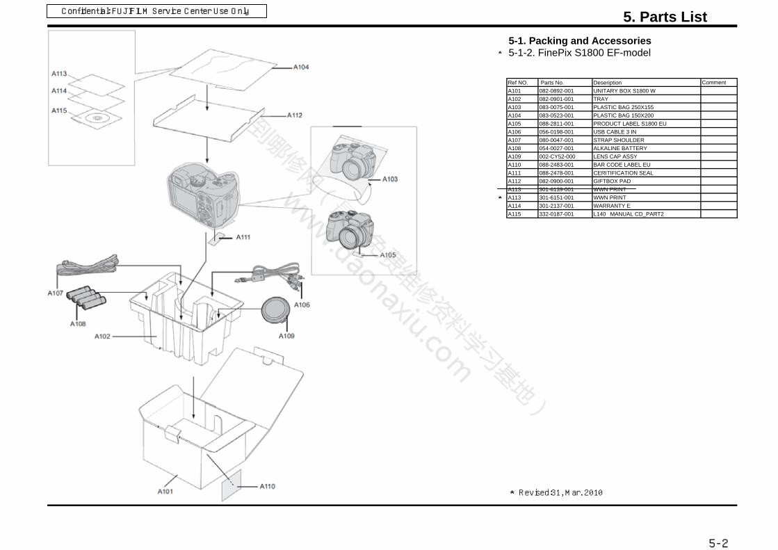
5-1. Packing and Accessories 5-1-2. FinePix S1800 EF-model
Ref NO. Parts No. Deseription CommentA101 082-0892-001 UNITARY BOX S1800 WA102 082-0901-001 TRAYA103 083-0075-001 PLASTIC BAG 250X155A104 083-0523-001 PLASTIC BAG 150X200A105 088-2811-001 PRODUCT LABEL S1800 EUA106 056-0198-001 USB CABLE 3 INA107 080-0047-001 STRAP SHOULDERA108 054-0027-001 ALKALINE BATTERYA109 002-CY52-000 LENS CAP ASSYA110 088-2483-001 BAR CODE LABEL EUA111 088-2478-001 CERITIFICATION SEALA112 082-0900-001 GIFTBOX PADA113 301-6139-001 WWN PRINT
A113 301-6151-001 WWN PRINTA114 301-2137-001 WARRANTY EA115 332-0187-001 L140MANUAL CD_PART2
5. Parts ListConfidential: FUJIFILM Service Center Use Only
Revised:31, Mar. 2010
5-2

5-1. Packing and Accessories 5-1-3. FinePix S1800 EE-model
Ref NO. Parts No. Deseription CommentA101 082-0892-001 UNITARY BOX S1800 WA102 082-0901-001 TRAYA103 083-0075-001 PLASTIC BAG 250X155A104 083-0523-001 PLASTIC BAG 150X200A105 088-2811-001 PRODUCT LABEL S1800 EUA106 056-0198-001 USB CABLE 3 INA107 080-0047-001 STRAP SHOULDERA108 054-0027-001 ALKALINE BATTERYA109 002-CY52-000 LENS CAP ASSYA110 088-2483-001 BAR CODE LABEL EUA111 088-2478-001 CERITIFICATION SEALA112 082-0900-001 GIFTBOX PADA113 301-6139-001 WWN PRINT
A113 301-6151-001 WWN PRINTA114 301-0114-001 BASIC MANUAL ENA115 332-0187-001 L140MANUAL CD_PART2
5. Parts ListConfidential: FUJIFILM Service Center Use Only
Revised:31, Mar. 2010
5-3

5-1. Packing and Accessories 5-1-4. FinePix S1800 EG-model
Ref NO. Parts No. Deseription CommentA101 082-0892-001 UNITARY BOX S1800 WA102 082-0901-001 TRAYA103 083-0075-001 PLASTIC BAG 250X155A104 083-0523-001 PLASTIC BAG 150X200A105 088-2811-001 PRODUCT LABEL S1800 EUA106 056-0198-001 USB CABLE 3 INA107 080-0047-001 STRAP SHOULDERA108 054-0027-001 ALKALINE BATTERYA109 002-CY52-000 LENS CAP ASSYA110 088-2482-001 BAR CODE LABEL EGA111 088-2478-001 CERITIFICATION SEALA112 082-0900-001 GIFTBOX PADA113 301-6139-001 WWN PRINT
A113 301-6151-001 WWN PRINTA114 301-2137-001 WARRANTY EA115 301-0114-001 BASIC MANUAL ENA116 332-0187-001 L140MANUAL CD_PART2
5. Parts ListConfidential: FUJIFILM Service Center Use Only
Revised:31, Mar. 2010
5-4
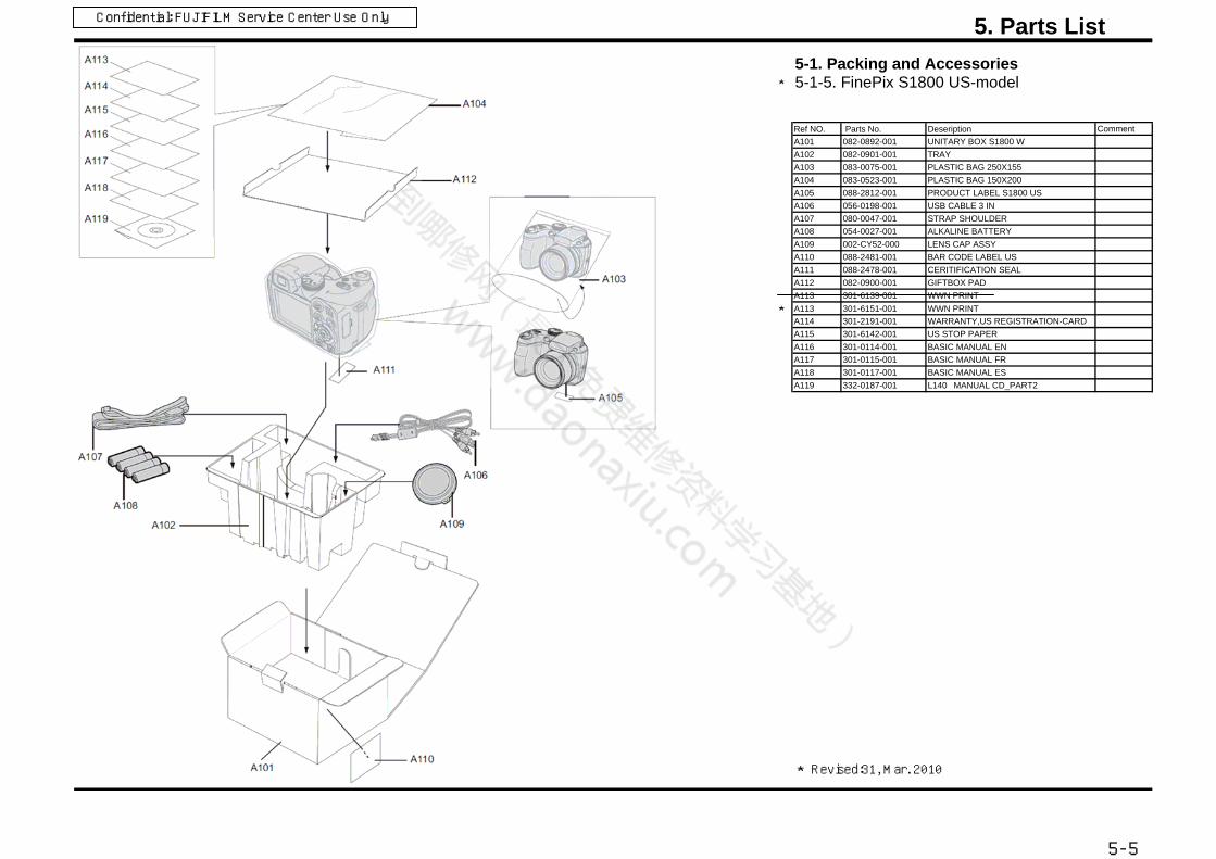
5-1. Packing and Accessories 5-1-5. FinePix S1800 US-model
Ref NO. Parts No. Deseription CommentA101 082-0892-001 UNITARY BOX S1800 WA102 082-0901-001 TRAYA103 083-0075-001 PLASTIC BAG 250X155A104 083-0523-001 PLASTIC BAG 150X200A105 088-2812-001 PRODUCT LABEL S1800 USA106 056-0198-001 USB CABLE 3 INA107 080-0047-001 STRAP SHOULDERA108 054-0027-001 ALKALINE BATTERYA109 002-CY52-000 LENS CAP ASSYA110 088-2481-001 BAR CODE LABEL USA111 088-2478-001 CERITIFICATION SEALA112 082-0900-001 GIFTBOX PADA113 301-6139-001 WWN PRINT
A113 301-6151-001 WWN PRINTA114 301-2191-001 WARRANTY,US REGISTRATION-CARDA115 301-6142-001 US STOP PAPERA116 301-0114-001 BASIC MANUAL ENA117 301-0115-001 BASIC MANUAL FRA118 301-0117-001 BASIC MANUAL ESA119 332-0187-001 L140MANUAL CD_PART2
5. Parts ListConfidential: FUJIFILM Service Center Use Only
Revised:31, Mar. 2010
5-5

5-1. Packing and Accessories 5-1-6. FinePix S1850 EG-model
Ref NO. Parts No. Deseription CommentA101 082-0928-001 UNITARY BOX S1850 EGA102 082-0901-001 TRAYA103 083-0075-001 PLASTIC BAG 250X155A104 083-0523-001 PLASTIC BAG 150X200A105 088-2917-001 PRODUCT LABEL S1850 EGA106 056-0198-001 USB CABLE 3 INA107 080-0047-001 STRAP SHOULDERA108 054-0027-001 ALKALINE BATTERYA109 002-CY52-000 LENS CAP ASSYA110 088-2482-001 BAR CODE LABEL EGA111 088-2478-001 CERITIFICATION SEALA112 082-0900-001 GIFTBOX PADA113 301-6151-001 WWN PRINTA114 301-2137-001 WARRANTY EA115 301-0114-001 BASIC MANUAL ENA116 332-0187-001 L140MANUAL CD_PART2
5. Parts ListConfidential: FUJIFILM Service Center Use Only
Revised:31, Mar. 2010
5-6

5-1. Packing and Accessories5-1-7. FinePix S1880 CH-model
Ref No. Parts No. Deseription CommentA101 082-0893-001 UNITARY BOX S1880 CHA102 082-0901-001 TRAYA103 083-0075-001 PLASTIC BAG 250X155A104 083-0523-001 PLASTIC BAG 150X200A105 088-2813-001 PRODUCT LABEL S1880 CHA106 056-0198-001 USB CABLE 3 INA107 080-0047-001 STRAP SHOULDERA108 054-0027-001 ALKALINE BATTERYA109 002-CY52-000 LENS CAP ASSYA110 088-2480-001 BAR CODE LABEL CHA111 088-2479-001 REGULATION SEALA112 082-0900-001 GIFTBOX PADA113 301-0121-001 MANUAL ZHA114 332-0187-001 L140MANUAL CD_PART2A115 301-6120-001 CERTIFICATEA116 301-2181-001 WARRANTY C
5. Parts ListConfidential: FUJIFILM Service Center Use Only
5-7

5-1. Packing and Accessories 5-1-8. FinePix S1900 EE-model
Ref NO. Parts No. Deseription CommentA101 082-0927-001 UNITARY BOX S1900 WA102 082-0901-001 TRAYA103 083-0075-001 PLASTIC BAG 250X155A104 083-0523-001 PLASTIC BAG 150X200A105 088-2911-001 PRODUCT LABEL S1900 EUA106 056-0198-001 USB CABLE 3 INA107 080-0047-001 STRAP SHOULDERA108 054-0027-001 ALKALINE BATTERYA109 002-CY52-000 LENS CAP ASSYA110 088-2483-001 BAR CODE LABEL EUA111 088-2478-001 CERITIFICATION SEALA112 082-0900-001 GIFTBOX PADA113 301-6139-001 WWN PRINT
A113 301-6151-001 WWN PRINTA114 301-0114-001 BASIC MANUAL ENA115 332-0187-001 L140MANUAL CD_PART2
5. Parts ListConfidential: FUJIFILM Service Center Use Only
Revised:31, Mar. 2010
5-8
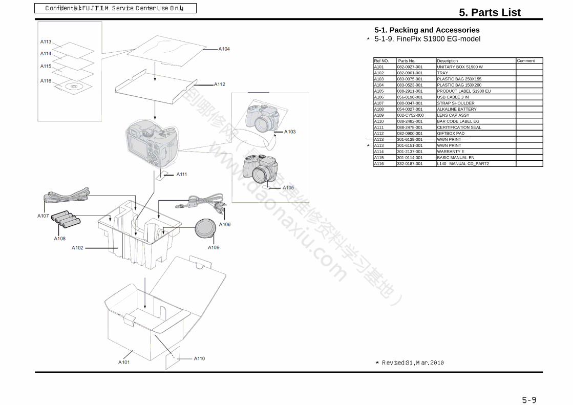
5-1. Packing and Accessories 5-1-9. FinePix S1900 EG-model
Ref NO. Parts No. Deseription CommentA101 082-0927-001 UNITARY BOX S1900 WA102 082-0901-001 TRAYA103 083-0075-001 PLASTIC BAG 250X155A104 083-0523-001 PLASTIC BAG 150X200A105 088-2911-001 PRODUCT LABEL S1900 EUA106 056-0198-001 USB CABLE 3 INA107 080-0047-001 STRAP SHOULDERA108 054-0027-001 ALKALINE BATTERYA109 002-CY52-000 LENS CAP ASSYA110 088-2482-001 BAR CODE LABEL EGA111 088-2478-001 CERITIFICATION SEALA112 082-0900-001 GIFTBOX PADA113 301-6139-001 WWN PRINT
A113 301-6151-001 WWN PRINTA114 301-2137-001 WARRANTY EA115 301-0114-001 BASIC MANUAL ENA116 332-0187-001 L140MANUAL CD_PART2
5. Parts ListConfidential: FUJIFILM Service Center Use Only
Revised:31, Mar. 2010
5-9

5-2. Mechanical Block
S1800/S1850/S1880/S1900
Ref No. Parts No Description Comment
M201 002-CY73-000 FRONT COVER ASSY B
M202 002-CY75-000 REAR COVER ASSY B
M203 002-CY76-000 BATTERY COVER ASSY B
M204 002-CY77-000 EVF ASSY
M205 002-CY79-000 FLASH BOTTOM ASSY
M206 002-CY81-000 TOP COVER CONST
M207 002-CY84-000 LENS CONST
M208 002-CY85-000 LCD HOLDER ASSY
M209 002-CY86-000 MAIN PWB ASSY
M210 002-CY88-000 TOP BOARD ASSY
M211 002-CY90-000 PCBA SHUTTER ASSY
M212 002-CY92-000 PCBA AF LED ASSY
M213 002-CY93-000 FRAME ASSY
M214 115-0088-101 LCD
M215 055-3004-001 EVF
M216 116-0545-001 MICROPHONE
M217 051-6246-011 LCD WINDOW
M218 081-0368-001 TAPE LCD WINDOW
M219 051-6256-001 CAP MYLAR
M220 052-0651-001 STRAP LEFT
M221 051-2091-011 FLASH TCOVER PI B
M222 051-6257-001 TOP BOARD MYLAR
M223 052-2593-001 FLASH HINGE
M224 059-0263-001 WIRE FFC
M225 085-0339-001 SCREW M1.7×3.5
M226 085-0351-001 TAPPING SCREW M1.7×4.5
M227 085-0352-001 TAPPING SCREW M1.7×4.5
M228 085-0340-001 TAPPING SCREW M1.7×3.5
M229 085-0341-001 TAPPING SCREW M1.7×3.0
M230 085-0343-001 TAPPING SCREW M1.4×3.0
5-10
Revised:31, Mar. 2010

5-3. Electrical parts
Electrical parts
Ref No. Parts No Comment
C152 217-0005-001
F600 213-0035-001
5-11
MAIN PWB ASSYDescription
BACKUP BATTERY
FUSE 6V 1.1A
The components indicated by mark are critical for safety.When indicated parts by reference number, please includethe board name.
* Due to standardization, replacement in the parts list maybe different from the parts list specified in the circuit or thecomponents used on the set.

6.Appendix
6-1 List of Related Technical Updates Issued To ensure that after-sales srevice is performed accuratety, keep a record here of the technical updates issued that cover this
device.
Technical Update No. Date Title Details/Other
2009-184
11, Dec. 2009 Service manual revision Revised pages: P5-1 to P5-12,
2010-001
05, Jan. 2010
The adjustment software
release and the
service manual revision
Revised pages: P1-1 toP1-12,P2-1toP2-5,P3-1toP3-32,P4-1toP4-4
2010-064
31, Mar. 2010
The adjustment software
revision and the
service manual revision
Revised pages: P1-1 , P3-2toP3-32,P5-1toP5-6,P5-8toP5-10
6-1
Confidential: FUJIFILM Service Center Use Only

Midtown West, 7-3, Akasaka 9-chome, Minato-ku, Tokyo 107-0052, Japan