digital closed-loop control electronics re 30543-b/12.10 ... · 10.2 disassembling the hydraulic...
TRANSCRIPT
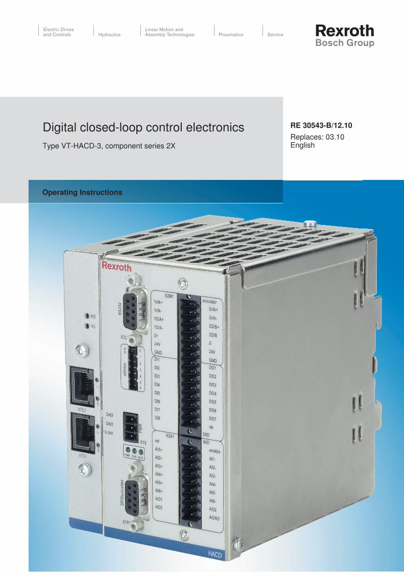
RE 30543-B/12.10Replaces: 03.10English
Operating Instructions
Digital closed-loop control electronicsType VT-HACD-3, component series 2X

The data specified above only serve to describe the product. No statements concerning a certain condition or suitability for a certain application can be derived from our information. The information given does not release the user from the obligation of own judgment and verification. It must be remembered that our products are subject to a natural process of wear and aging.
© This document, as well as the data, specifications and other information set forth in it, are the exclusive property of Bosch Rexroth AG. It may not be reproduced or given to third parties without its consent.
The cover page shows a sample configuration. The product supplied may therefore differ from the photo shown.
The original operating instructions were prepared in German.

RE 30543-B/12.10 | VT-HACD-3, component series 2X Bosch Rexroth AG 3/40
Content
Inhalt1 About this document ......................................................................................4
1.1 Related documents ...................................................................................41.2 Abbreviations used ...................................................................................4
2 General safety instructions............................................................................52.1 Intended use .............................................................................................52.2 Improper use .............................................................................................52.3 Safety instructions in this document .........................................................62.4 Adhere to the following instructions ..........................................................7
3 Scope of delivery ..........................................................................................104 Product description ......................................................................................11
4.1 Performance description .........................................................................114.2 Device description...................................................................................184.3 Displays ..................................................................................................224.4 Product identification...............................................................................234.5 Profibus DP .............................................................................................234.6 Ethernet IP ..............................................................................................234.7 PROFINET RT ........................................................................................23
5 Transport and storage ..................................................................................235.1 Storing the VT-HACD-3-2X ....................................................................23
6 Assembly .......................................................................................................246.1 Unpacking ...............................................................................................246.2 Installation conditions..............................................................................246.3 Assembling the VT-HACD-3-2X .............................................................24
7 Commissioning .............................................................................................287.1 “BODAC” configuration software.............................................................287.2 First commissioning of the VT-HACD-3-2X ............................................297.3 Re-commissioning after repair and maintenance ...................................29
8 Operation .......................................................................................................308.1 “WinView” diagnosis software .................................................................30
9 Maintenance ..................................................................................................319.1 Cleaning and care (maintenance) ...........................................................319.2 Repair .....................................................................................................31
10 Disassembly and replacement ....................................................................3210.1 Preparing for disassembly ......................................................................3210.2 Disassembling the hydraulic power unit..................................................3210.3 Preparing the components for storage/further use .................................33
11 Disposal .........................................................................................................3411.1 Environmental protection ........................................................................3411.2 Return to Bosch Rexroth.........................................................................3411.3 Packagings .............................................................................................3411.4 Materials used.........................................................................................3411.5 Recycling ................................................................................................34
12 Extension and conversion ...........................................................................3512.1 Optional accessories...............................................................................35
13 Troubleshooting ............................................................................................3513.1 How to proceed for troubleshooting ........................................................35
14 Technical data ...............................................................................................3615 Appendix ........................................................................................................36
15.1 Address directory ....................................................................................36
4/40 Bosch Rexroth AG VT-HACD-3, component series 2X | RE 30543-B/12.10
About this document
1 About this documentThese instructions contain important information on the safe and appropriate assembly, transport, commissioning, operation, maintenance, disassembly and simple troubleshooting of the VT-HACD-3-2X digital closed-loop control electronics.Read these instructions completely, especially chapter 2 “General safety instructions”, before working with the digital closed-loop control electronics VT-HACD-3-2X
Related documents1.1 The digital closed-loop control electronics VT-HACD-3-2X is a system component.Also observe the instructions for the other system components.Also observe the instructions in the following manuals:
System documentation from the system manufacturer •Technical data sheet RE 30543 •“BODAC” online help, software description RE 30543-01-B •Commissioning instructions PROFIBUS interface RE 30543-01-Z •Commissioning instructions Ethernet/IP interface RE 30543-04-Z •Commissioning instructions PROFINET RT interface RE 30543-05-Z •Declaration of environmental compatibility RE 30543-U •General information on the maintenance and commissioning of hydraulic •components RE 07800/RE 07900
The configuration software “BODAC” can be downloadedfrom the internet free of charge.Download: www.boschrexroth.com/hacdQueries: [email protected]
Also observe the generally applicable, legal or otherwise binding regulations of the European or national legislation and the rules for the prevention of accidents and for environmental protection applicable in your country.
Abbreviations1.2 usedAbbreviationsTable 1:
Abbreviation MeaningHACD VT-HACD-3-2XCAN Controller Area NetworkEMC Electromagnetic compatibilityAGND Analog GroundDOx Digital outputDIx Digital inputAOx Analog outputAIx Analog inputCLK Clock (SSI encoder)D/A Digital / AnalogNS Network statusL LinkS StatusPWR Voltage supply (power)
RE 30543-B/12.10 | VT-HACD-3, component series 2X Bosch Rexroth AG 5/40
General safety instructions
General safety instructions2 The VT-HACD-3-2X digital electronics has been manufactured according to the accepted rules of current technology. There is, however, still a risk of personal injury or damage to property if the following safety instructions and warnings contained in this document are not observed.
Read these instructions completely and thoroughly before working with the HACD.Keep these instructions in a location where they are accessible to all users at all times.Always include the operating instructions when you pass the HACD on to third parties.Only operate the HACD in a technically immaculate condition and as intended, in a safety- and risk-conscious manner, considering these instructions.In case of failures impairing the safety and modifications to the operating behavior, shut down the HACD immediately and report the failures to the responsible personnel.
Intended use2.1 The exclusive intended purpose of the HACD is the installation in a control cabinet. The product may be commissioned only if it is integrated in the machine/system for which it is designed.Observe the operating conditions and performance limits specified in the technical data RE 30543.The HACD is intended for the use in machine tools, plastic and special-purpose machines as well as in presses and transfer systems. It can be used as control module for the generation, connection and standardization of signals or as controller module for closed control loops with PIDT1 controller and optional state feedback.When using the unit, you moreover need superordinate control logics with corresponding I/O components that in connection with the HACD are responsible for the holistic control of the machine's motion sequence and also its monitoring as regards safety.The HACD must not be used in explosive environments.The HACD is a work appliance and not designed for private use.Intended use includes having completely read and understood these instructions, especially the chapter 2 “General safety instructions”.
Improper use2.2 Any use deviating from the intended use is not intended and thus not admissible.Bosch Rexroth AG does not assume any liability for damages caused by not intended use. The user assumes all risks involved with not intended use.

6/40 Bosch Rexroth AG VT-HACD-3, component series 2X | RE 30543-B/12.10
General safety instructions
Qualification of personnelAssembly, commissioning and operation, disassembly, service (including maintenance and repair) require basic mechanical, hydraulic, electrical, and control knowledge as well as knowledge of the appropriate technical terms. In order to ensure operational safety, these activities may only be carried out by qualified technical personnel or an instructed person under the direction and supervision of a qualified person.Qualified personnel are those who can recognize potential hazards and apply the appropriate safety measures due to their professional training, knowledge and experience, as well as their understanding of the relevant conditions pertaining to the work to be undertaken. Qualified personnel must observe the rules/laws relevant to the specific subject area.
Safety instructions in this document2.3 In these instructions, there are safety instructions before an instruction whenever there is a risk of personal injury or damage to the equipment. The measures described for preventing these hazards must be observed.
Safety instructions are set out as follows:
Type of riskConsequences
Precautions
Warning sign (warning triangle): Draws attention to the hazard •Signal word: Identifies the degree of hazard •Type of risk: Specifies the type or source of the hazard •Consequences: Describes the consequences of non-compliance •Precautions: Specifies how the hazard can be prevented •
The signal words have the following meaning:
Signal word / warning sign Application
DANGER! Indicates an imminently hazardous situation which, if not avoided, will certainly result in death or serious injury.
WARNING! Indicates a potentially hazardous situation which, if not avoided, could result in death or serious injury.
CAUTION! Indicates a potentially hazardous situation which, if not avoided, could result in minor or moderate injury or damage to equipment.
If this information or further notes and additional information are nt observed, the operating procedure may be impaired.
SIGNAL WORD!

RE 30543-B/12.10 | VT-HACD-3, component series 2X Bosch Rexroth AG 7/40
General safety instructions
Adhere to the following instructions2.4
General instructions2.4.1 Observe the regulations for accident prevention and environmental protection •for the country where the product is used and at the workplace.Exclusively use Rexroth products in good technical order and condition. •Check the product for visible defects, • for example loose seat of screws, loose seat of the connector plugs and connection lines, mechanical damage, etc.You must generally not modify or retrofit the product. •Only use the product within the performance range provided in the technical •data RE 30543.Persons who assemble, operate, disassemble or maintain Rexroth products •must not consume any alcohol, drugs or pharmaceuticals that may affect their ability to respond.Make sure that all safety equipment belonging to the product is present, has •been installed properly and is fully functional. Do not displace, bypass or disable the safety equipment.If it should be necessary to disable any safety equipment temporarily, for •example for commissioning or maintenance work, always take the appropriate measures to ensure that no hazard to a person's life or health or to property may occur. Also observe the superordinate operating instructions for the machine or system.The warranty only applies to the delivered configuration. •The warranty will not apply if the product is incorrectly assembled, not used as •intended and/or handled improperly.Do not expose the product to any mechanical loads under any circumstances. •Do not use electrical signals led out of the HACD (e.g. “No error” signal) for •switching safety-relevant machine functions! (For this, also see European Standard “Safety requirements for fluid power systems and their components - Hydraulics” EN 982.)If electromagnetic interference is to be anticipated, suitable measures must •be taken to ensure the function (depending on the application, e.g. shielding, filtration)!In order to ensure adequate cooling, make sure that the top and bottom •ventilation slots are not obstructed by periphery devices.

8/40 Bosch Rexroth AG VT-HACD-3, component series 2X | RE 30543-B/12.10
General safety instructions
During assembly2.4.2 Make sure the relevant system component is de-pressurized and de-energized •before assembling the product or when connecting and disconnecting plugs. Protect the system component against being switched on.Do not install the HACD next to power electronic units (e.g. frequency •converter). The power pack of the HACD must be installed as close as possible to the HACD.Keep connections for the voltage supply as short as possible. Pass supply and •return lines (+24 V/GND) together. Voltage 18–36 V. Residual ripple < 1.5 Vpp, I = 1–4 A (depends on the HACD variant and the additional supplied components).Observe the highest possible separation of signal and load lines and do not lay •the same parallel. Do not lead signal lines through strong magnetic fields. If possible, pass signal lines without interruption. If intermediate terminals are necessary, use a terminal block with shield bus.For signal lines, only cables with a copper braid screen should be used. The •cable screen is extensively connected with the metallized connector housing and usually only on the HACD side. This is achieved by pushing the screen back and clamping under the pull relief.Cables should only have the actually required number of wires. If this is not possible, the remaining wires should be laid to GND on both sides. By snapping the housing of the HACD on a conductive assembly rail, the earth •connection to the control cabinet back wall is established. This constitutes the HF earthing of the HACD.Lay the cables and lines so that they cannot be damaged and no one can trip •over them.The environment must be free from electrically conductive contamination (acids, •bases, corrosive agents, salts, metal vapors, etc.) and must not be exposed to these substances.No silicone-containing sealing, adhesive, or insulating agents must be used. •Ensure a maintenance-friendly installation, i.e. simple access to the connection •lines. Free access to the connection side must be guaranteed.Before installation note down the information on the nameplates. •If after the installation, nameplates are not visible or readable any more, this data will be quickly available to you at any time.Do not use electrical signals led out of the HACD (e.g. the “Ready for •Operation” signal) for switching safety-relevant machine functions! (For this, also see European Standard “Safety requirements for fluid power systems and their components - Hydraulics” EN982:1996).

RE 30543-B/12.10 | VT-HACD-3, component series 2X Bosch Rexroth AG 9/40
General safety instructions
During commissioning2.4.3 Let the product acclimate itself for several hours before commissioning, as •otherwise water may condense in the housing.Make sure that all electrical connections are either used or covered. •Commission the product only if it is installed completely.
During operation2.4.4 Only authorized staff is allowed to operate the setting mechanisms of the •components or parts, under the proviso that the hydraulic system is used as intended.Only persons who have been authorized by the operator may be granted •access to the immediate vicinity of operation. This also applies during machine standstill.In case of emergency, failure, or in case of other irregularities switch off the •system and secure it against restart.
Disposal2.4.5 Dispose of the product in accordance with the currently applicable national •regulations in your country.

10/40 Bosch Rexroth AG VT-HACD-3, component series 2X | RE 30543-B/12.10
Scope of delivery
Scope of delivery3 The delivery contents include:
Digital closed-loop control electronics VT-HACD-3-2X •Mating connector for •
Port X1S (Phoenix Mini Combicon 3-pole) –Port X2A1 (Weidmüller B2L 3.5/18 LH SN SW) –Port X2M1 (Weidmüller B2L 3.5/30 LH SN SW –
The configuration software “BODAC” can be downloadedfrom the internet free of charge.Download: www.boschrexroth.com/hacdQueries: [email protected]
Check the delivery contents for completeness, for possible transport damage, for suitable and complete operating instructions. Enquire about incomplete operating instructions.
RE 30543-B/12.10 | VT-HACD-3, component series 2X Bosch Rexroth AG 11/40
Product description
Product description4
Performance description4.1 The micro controller of the VT-HACD-3-2 X digital closed-loop control electronics controls the entire process, makes adjustments and establishes links and implements closed control loops. Data for configuration, command values and parameters are stored in a non-volatile FLASH memory.The HACD is mounted on a top hat rail.The entire configuration is made with BODAC software. The card does not include any jumpers or similar. For configuration, the HACD must be connected via a serial interface (RS 232, 1:1 cable). The entire configuration as well as parameterization and diagnosis are made by means of the BODAC user interface.The VT-HACD-3-2X digital closed-loop control electronics is suitable for the use as
freely configurable control variant with PIDT1 controller and optional •state controlcontrol of position / pressure / force and speed •substitutional closed-loop control (position, pressure or force) •command value electronics •

12/40 Bosch Rexroth AG VT-HACD-3, component series 2X | RE 30543-B/12.10
Product description
User programming with PCConvenient administration of machine and measurement data on the PCThe configuration software “BODAC” can be downloadedfrom the internet free of charge.Download: www.boschrexroth.com/hacdQueries: [email protected]
• Digital inputs and outputsAnalog inputs and outputs •PROFIBUS DPV0, EtherNet/IP or PROFINET RT for communication with •superior control (observe the order code)
Controller4.1.1 If the HACD is used as controller module, you must select “Controller” for the signal connection [8].The LCx signals indicate the command value branch, the LFBx signals indicate the actual value branch. [8]Both SSI encoder or incremental encoder [2] (digital measuring system) and one or more analog sensors can be used as actual value signal.The controller structure is designed as PIDT1 controller, whereas each share can be activated or deactivated individually. Thus, also a P or PT1 controller can be implemented for example. The I share can additionally be controlled via a window (upper and lower limit).Control parameters can be set in blocks or independently of blocks.In the structure editor, you can use state feedback for damping the controller output.
Position controller:
PDT1 controller •Linear gain characteristic •Gain characteristics depending on direction •Gain modification possible through the program •Adjustment of the characteristic curve for the valve •Fine positioning by I share •Residual voltage principle •Equalization of zero point errors •State feedback by means of •
Pressure –Differential pressure –Position –
Command value intrusion •
Pressure/force controller:
PIDT1 controller •I share connectible via window •Differential pressure evaluation •Command value intrusion •
Programming
Process connection
Controller functionality

RE 30543-B/12.10 | VT-HACD-3, component series 2X Bosch Rexroth AG 13/40
Product description
Velocity controller:
PI controller •I share connectible via window •
Monitoring functions:
Dynamic lag error monitoring •Cable break monitoring for incremental and SSI encoder •Cable break monitoring for sensors •Cable break monitoring for analog signals •The monitoring functions must be activated by the customer in the parameter file •
Controller structureFig. 1:
Structure editor4.1.2 The structure editor is enabled. Own motion sequences can be established. For this purpose, 32 blocks are available.Each block contains: Command value, acceleration, deceleration (velocity +, velocity –) and controller parameters.Blocks are activated by setting trigger requirements: setting digital inputs, comparing signals with freely definable thresholds or expiration of the waiting times.
Also observe the instructions in the following manuals:
“BODAC” online help, software description RE 30543-01-B •
Controller structure
P
I
DT1
– –
+
+
+
–
T1
D
Command value provision
Command value
Actual value
Actuatingvariable
State feedbackSignal
DT1 (actual value)

14/40 Bosch Rexroth AG VT-HACD-3, component series 2X | RE 30543-B/12.10
Product description
Analog voltage or current inputs (1 1a: High-impedance input AI1)SSI or incremental2 Release input and digital inputs3 Analog input adjustment4 Switching matrix5 Math. connection and/or inputs6 32 blocks for command value generation, controller parameter changeover switch7 Math. connection and/or controller8
VT-HACD-3-2X block diagram, mode 3 - structure editorFig. 2:
C1-1
C2-1
C3-1
FB1-1
FB2-1
FB3-1
C1-2
C2-2
C3-2
FB1-2
FB2-2
FB3-2
LC1
LC3
LFB1
LFB3
C1
C2
C3
FB1
FB2
FB3
U
U/IU
U
U/IU
U/IU
U/IU
IN1
IN2
IN3
IN4
IN5
IN6
AI1+
INC
1D/A+
2D/B– INC
1D/A–2D/B+
Z–Z+
SSI
1CLK+
1D/A–
SSI11CLK–
1D/A+
U/I
U/I
DI1DI2DI3DI4DI5DI6DI7DI8
DC
DC
18 -30 V
GND
71 4 5
6
3
3
+, –, *, /MIN, MAX
Limit, Jump
+, –, *, /MIN, MAX
Limit, JumpRatio
+, –, *, /MIN, MAX
Limit, JumpRatio
+, –, *, /MIN, MAX
Limit, JumpRatio
+, –, *, /MIN, MAX
Limit, Jump
+, –, *, /MIN, MAX
Limit, Jump2
RS 232
PROFIBUS
Ethernet
AI1–
AI2+AI2–
AI3+AI3–
AI4+AI4–AI5+AI5–
AI6+AI6–
SSI
2CLK+
2D/A–
SSI22CLK–
2D/A+
1
2
3
LC2
LFB2
6
6
2
2
PWR RUN
GND
1a
T1 Lag
T1 Lag
T1 Lag
T1 Lag
T1 Lag
T1 Lag
Command value internal + variableVelocity +/–S ramp +/–
Command value internal + variableVelocity +/–S ramp +/–
Command value internal + variableVelocity +/–S ramp +/–
LFB1 = Variable
LFB2 = Variable
LFB3 = Variable
Controller parameter
Controller parameter
Controller parameter
Digital inputs Digital outputs
Internal flags Error Thresholds
Dwell time Block time
Trigger conditions 1 ANDOR
Trigger conditions 2
RE 30543-B/12.10 | VT-HACD-3, component series 2X Bosch Rexroth AG 15/40
Product description
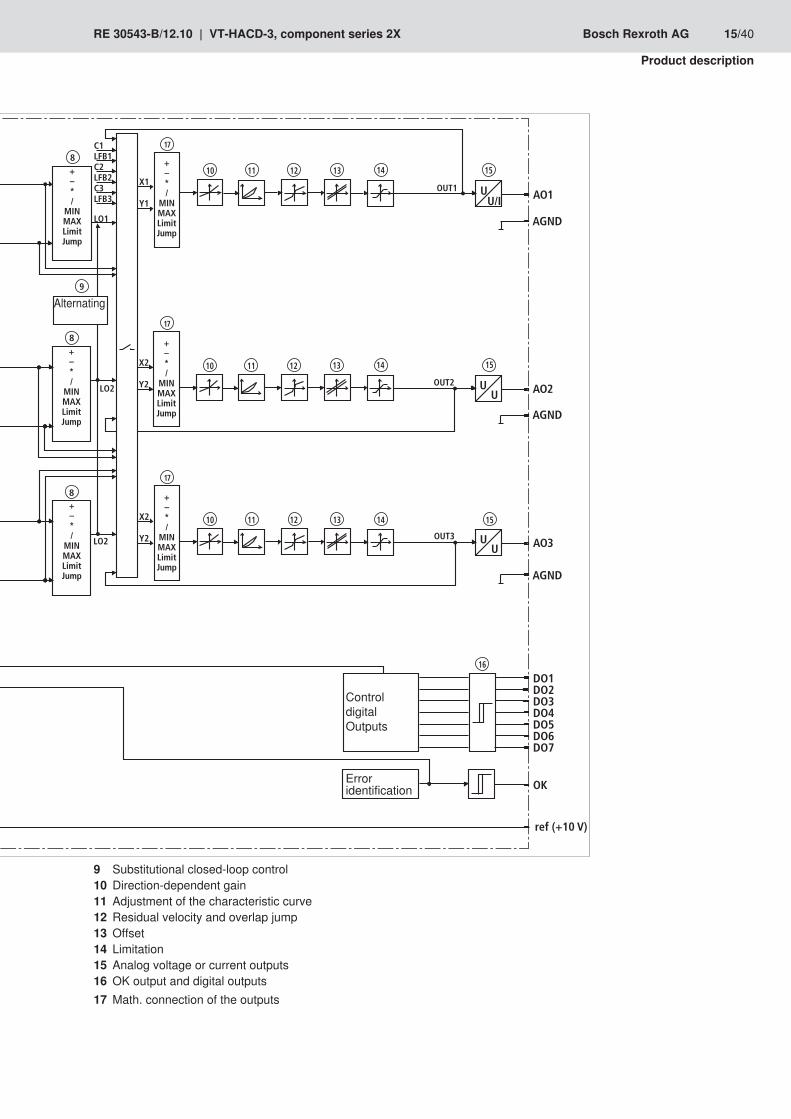
Substitutional closed-loop control9 Direction-dependent gain10 Adjustment of the characteristic curve11 Residual velocity and overlap jump12 Offset13 Limitation14 Analog voltage or current outputs15 OK output and digital outputs16 Math. connection of the17 outputs
U/IU
UU
LO1
LO2
AO1
AO3
AGND
17
X1
Y1
OUT1
OUT3
C1LFB1C2LFB2C3LFB3
X2
Y2
OK
DO1DO2DO3DO4DO5DO6DO7
ref (+10 V)
8
8
16
9
17
+–*/
MINMAXLimitJump
+–*/
MINMAXLimitJump
+–*/
MINMAXLimitJump
+–*/
MINMAXLimitJump
10 11 12 13 14 15
10 11 12 13 14 15
1
2
3
UULO2 AO2
OUT2
X2
Y2
8
17
+–*/
MINMAXLimitJump
+–*/
MINMAXLimitJump
10 11 12 13 14 15
AGND
AGND
ControldigitalOutputs
Erroridentification
Alternating

16/40 Bosch Rexroth AG VT-HACD-3, component series 2X | RE 30543-B/12.10
Product description
Error identification and treatment4.1.3 The HACD supports various error monitoring options:
Monitoring of analog inputs for lower deviation or exceedance of the range •Monitoring the travel sensors for cable break •Control error monitoring when configuring the HACD as controller •Monitoring supply voltage, any internal voltage as well as the +10 V reference •voltageMonitoring the micro controller (watchdog) as well as the memory (checksum) •
The error monitoring as well as its reaction can be configured as well. Error monitoring must be activated by the customer.
Signal connections4.1.4 The HACD has various signal connection options both for the input and the output side, whereas 2 signals each can be connected.These are functions such as addition, subtraction, multiplication, division as well as minimal/maximal value generator, area ration and limiter:
+ = Addition: Z = X + Y •– = Subtraction: Z = X – Y •* = Multiplication: Z = X * Y / 100 •/ = Division: Z = X / Y * 100 •MIN = Minimum value generator: Z = MIN (X, Y) •MAX = Maximum value generator: Z = MAX (X, Y) •RATIO = Ratio input: • For RATIO > 1: Z = X * RATIO – Y • For RATIO < 1: Z = X – Y / RATIO (e.g. area ratio differential pressure •measurement)LIMIT = Signal limiter: Z = MIN (|X|, |Y|) * X / |X| •JUMP = Jump generator: Z = MAX (|X|, |Y|) * X / |X| •with Z ... result •X … 1. signal •Y … 2. signal •T1 Lag = Low-pass filter •
For further notes see online help of BODAC RE 30543-01-B
Inputs and outputs4.1.5 The 6 analog inputs can be switched between±10 V, 0…10 V, 0…20 mA and 4…20 mA using the software. The input resistance is 300 kOhm ±5 %The analog output AO1 can be switched between ±10 V, 0…10 V, 0…20 mA and 4…20 mA using the software. AO2 and A03 is adjusted to a fixed value of ±10 V. The output is switched so that the whole range of the analog-digital connector is used. Both working range and error identification can be defined for all analog inputs.The analog outputs can be adjusted by means of amplification and offset.The HACD has 9 digital inputs and 8 digital outputs.Inputs have the enable functionality (X2A1, enable), digital inputs have the OK functionality (X2M1, ok).
Analog I/O
Digital l/O

RE 30543-B/12.10 | VT-HACD-3, component series 2X Bosch Rexroth AG 17/40
Product description
Further digital inputs are used for the triggering of blocks (see blocks and triggering).The function of each digital output can be determined by the selection from a predefined list:
Command value = Actual value •Actual value higher or lower than the adjustable threshold •Waiting time completed •Ramp completed •Error flag •Controller active •Error flag set •Table completed •Absolute value higher or lower than window •Error status •Block timeout •
18/40 Bosch Rexroth AG VT-HACD-3, component series 2X | RE 30543-B/12.10
Product description
Device description4.2
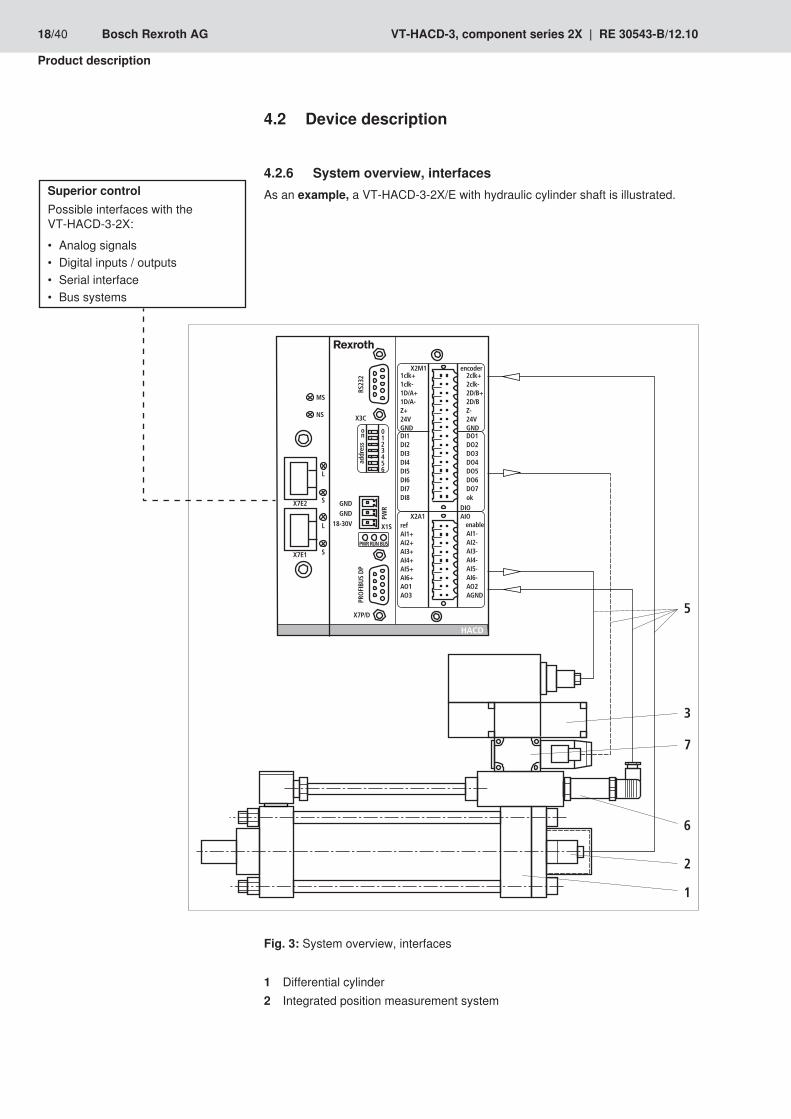
System overview, interfaces4.2.6 As an example, a VT-HACD-3-2X/E with hydraulic cylinder shaft is illustrated.
System overview, interfacesFig. 3:
Differential cylinder1 Integrated position measurement system2
Superior controlPossible interfaces with the VT-HACD-3-2X:
Analog signals •Digital inputs / outputs •Serial interface •Bus systems •
RE 30543-B/12.10 | VT-HACD-3, component series 2X Bosch Rexroth AG 19/40
Product description
Continuous valve with integrated control electronics3 VT-HACD-3-2X/E or .../N4 Connection cable5 Pressure transducer6 Sandwich plate isolator valve (with plug-in switching amplifier)7
The following interfaces are possible between the superior control and the HACD:
Analog signals •Digital inputs/outputs •Serial interface •Bus systems (PROFIBUS DP) •EtherNet/IP •PROFINET RT •
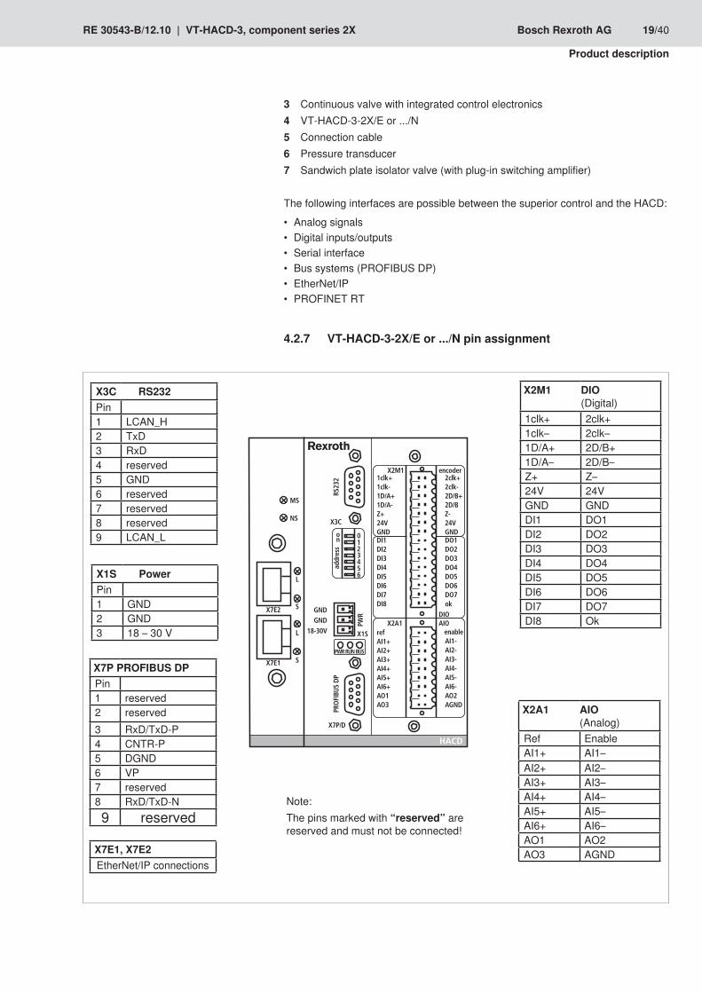
VT-HACD-3-2X/E or .../N pin assignment 4.2.7
X3C RS232Pin1 LCAN_H2 TxD3 RxD4 reserved5 GND6 reserved7 reserved8 reserved9 LCAN_L
Note:The pins marked with “reserved” are reserved and must not be connected!
X1S PowerPin1 GND2 GND3 18 – 30 V
X7P PROFIBUS DPPin1 reserved2 reserved3 RxD/TxD-P4 CNTR-P5 DGND6 VP7 reserved8 RxD/TxD-N9 reserved
X2M1 DIO(Digital)
1clk+ 2clk+1clk– 2clk–1D/A+ 2D/B+1D/A– 2D/B–Z+ Z–24V 24VGND GNDDI1 DO1DI2 DO2DI3 DO3DI4 DO4DI5 DO5DI6 DO6DI7 DO7DI8 Ok
X2A1 AIO(Analog)
Ref EnableAI1+ AI1–AI2+ AI2–AI3+ AI3–AI4+ AI4–AI5+ AI5–AI6+ AI6–AO1 AO2AO3 AGNDX7E1, X7E2
EtherNet/IP connections
���
���
����
����
���
������
������
�������
�������
����� ��� �
!
"#��
�����
�$�%�
��&� �!' ����'()*�'()���%#*��%#�+*������
�'()*�'()���%�*��%�+�������
��������������������$���
�������������$ )
��#���#��!�,(�
#��*#��*#��*#��*#��*#��*#�#�
#���#���#���#���#���#���#�#���
��-
.
�
.
�
��
�$/�
�$/�
&�

20/40 Bosch Rexroth AG VT-HACD-3, component series 2X | RE 30543-B/12.10
Product description
VT-HACD-3-2X unit dimensions4.2.8 (dimensions in mm)
Assembly on top hat rail TH 35-7.5 or TH 35-15 according to EN 60715
VT-HACD-3-2X/... unit dimensions (without Ethernet)Fig. 4:
Assembly on top hat rail TH 35-7.5 or TH 35-15 according to EN 60715
VT-HACD-3-2X/... unit dimensions (with Ethernet)Fig. 5:

RE 30543-B/12.10 | VT-HACD-3, component series 2X Bosch Rexroth AG 21/40
Product description
Digital position transducer4.2.9 If you use the HACD as controller module, digital position transducers of Type SSI or incremental can be used for actual value detection.The maximum frequency of the HACD incremental encoder (fG) is 250 kHz. The maximum travel velocity of the drive, the resolution (res) of the used encoder system and the possible signal evaluation by EXE determine the frequency (interpolation and digitization electronics).Encoder resolution at given maximum velocity:
fG [kHz] x EXERes [μm] ≥
v m x 103s
Velocity at specified encoder resolution:
103
Res [μm] x EXE x fG [kHz]v m ≤s
Limitation of use for the incremental encoder
Identification formulas

22/40 Bosch Rexroth AG VT-HACD-3, component series 2X | RE 30543-B/12.10
Product description
Displays4.3 The following LED displays are located at the front side of the the VT-HACD-3-2X/E or .../N :
LED displaysFig. 6:
Voltage supply is applied. HACD/... is initialized and in “RUN” mode.The LED flashes if the HACD is not initialized.The bus signal is applied.Network statusLED off = no IP addressLED green (flashing) = configurationLED green = connection establishedLED red (flashing) = connection interruptedLED red = double IP addressHACD status:LED green (flashing) = configurationLED green = HACD OKLED red = errorLink: On = Active; Off = No connection to the communication partnerTransmission status of the data (flashing = Receiving/sending EtherNet telegrams)
PWRRUN
BUSNS
MS
LS
RE 30543-B/12.10 | VT-HACD-3, component series 2X Bosch Rexroth AG 23/40
Transport and storage
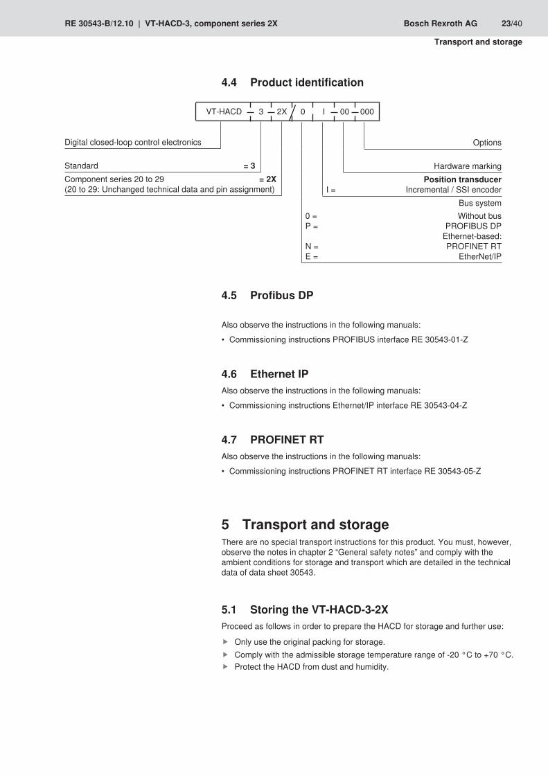
Product identification4.4
Profibus DP4.5
Also observe the instructions in the following manuals:
Commissioning instructions PROFIBUS interface RE 30543-01-Z •
Ethernet IP4.6 Also observe the instructions in the following manuals:
Commissioning instructions Ethernet/IP interface RE 30543-04-Z •
PROFINET RT4.7 Also observe the instructions in the following manuals:
Commissioning instructions PROFINET RT interface RE 30543-05-Z •
Transport and storage5 There are no special transport instructions for this product. You must, however, observe the notes in chapter 2 “General safety notes” and comply with the ambient conditions for storage and transport which are detailed in the technical data of data sheet 30543.
Storing the VT-HACD-3-2X 5.1 Proceed as follows in order to prepare the HACD for storage and further use:
Only use the original packing for storage. Comply with the admissible storage temperature range of -20 °C to +70 °C. Protect the HACD from dust and humidity.
Options
Hardware markingPosition transducer
I = Incremental / SSI encoderBus system
0 = Without busP = PROFIBUS DP
Ethernet-based:N = PROFINET RTE = EtherNet/IP
VT-HACD 3 2X 0 I 00 000
Digital closed-loop control electronics Standard = 3Component series 20 to 29 = 2X(20 to 29: Unchanged technical data and pin assignment)
24/40 Bosch Rexroth AG VT-HACD-3, component series 2X | RE 30543-B/12.10
Assembly
Assembly6
Unpacking6.1 Dispose of the packaging in accordance with the currently applicable national regulations in your country.
Installation conditions6.2 For installing the product always observe the ambient conditions specified in RE 30543.The HACD is mounted on a top hat rail in the control cabinet.
Assembling the VT-HACD-3-2X 6.3
Installing the VT-HACD-3-2X6.3.1
Risk of personal injury and damage to property!Assembly of the product requires basic electrical knowledge.
The product may only be assembled by qualified personnel.
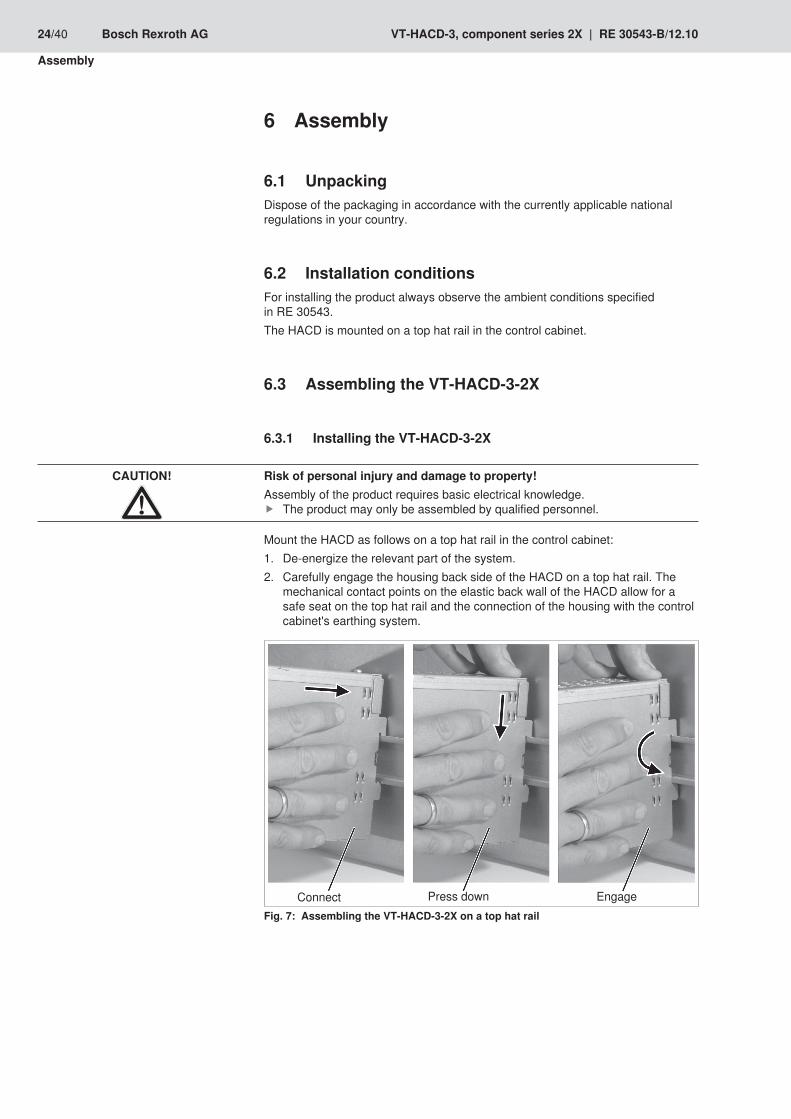
Mount the HACD as follows on a top hat rail in the control cabinet:De-energize the relevant part of the system.1. Carefully engage the housing back side of the HACD on a top hat rail. The 2. mechanical contact points on the elastic back wall of the HACD allow for a safe seat on the top hat rail and the connection of the housing with the control cabinet's earthing system.
Connect EngagePress down Assembling the VT-HACD-3-2X on a top hat railFig. 7:
CAUTION!
RE 30543-B/12.10 | VT-HACD-3, component series 2X Bosch Rexroth AG 25/40
Assembly
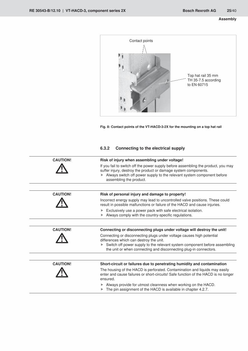
Contact points
Top hat rail 35 mmTH 35-7.5 according to EN 60715
Contact points of the VT-HACD-3-2X for the mounting on a top hat railFig. 8:
Connecting to the electrical supply6.3.2
Risk of injury when assembling under voltage!If you fail to switch off the power supply before assembling the product, you may suffer injury, destroy the product or damage system components.
Always switch off power supply to the relevant system component before assembling the product.
Risk of personal injury and damage to property!Incorrect energy supply may lead to uncontrolled valve positions. These could result in possible malfunctions or failure of the HACD and cause injuries.
Exclusively use a power pack with safe electrical isolation. Always comply with the country-specific regulations.
Connecting or disconnecting plugs under voltage will destroy the unit!Connecting or disconnecting plugs under voltage causes high potential differences which can destroy the unit.
Switch off power supply to the relevant system component before assembling the unit or when connecting and disconnecting plug-in connectors.
Short-circuit or failures due to penetrating humidity and contaminationThe housing of the HACD is perforated. Contamination and liquids may easily enter and cause failures or short-circuits! Safe function of the HACD is no longer ensured.
Always provide for utmost cleanness when working on the HACD. The pin assignment of the HACD is available in chapter 4.2.7.
CAUTION!
CAUTION!
CAUTION!
CAUTION!

26/40 Bosch Rexroth AG VT-HACD-3, component series 2X | RE 30543-B/12.10
Assembly
Proceed as follows when connecting the electrical supply of the HACD:De-energize the relevant part of the system.1. Check all cables for defects.2. Connect the voltage supply of the HACD using the X1S “Power” plug-in 3. connections.Connect the analog or digital inputs/outputs according to the desired 4. applications using the X2M1 “DIO” and X2A1 “AIO” plug-in connections.Switch on the voltage supply and make sure that the voltage is applied to the 5. HACD and/or the “PWR” LED is on, and that the bus signal is applied and/or the “BUS” LED is on.The HACD is connected to the electrical supply.

RE 30543-B/12.10 | VT-HACD-3, component series 2X Bosch Rexroth AG 27/40
Assembly
Wiring notes6.3.3
The HACD is engaged on an appropriate C busbar.1. The electronic housing and the filter elements on the electronic boards are 2. earthed vial the conductible connection between housing and C busbar -> back wall of the control cabinet.The cable shields of the encoder and AD/DA connections are connected 3. conductively with the C busbar using shield clamps. This connection of the shields with the C busbars to the back wall of the control cabinet must be close to the HACD. This connection is made by removing a piece of the cable sheath and then clamping the cable beneath the shield clamp. (see figure)Shield clamps, e.g.: Murrplastik SK 3-8 shield clamp 3-8mm 4. Item no.: 87201060 or SK 4-13.5 Item no.: 87201062. Both GND must be connected to X1S (power)5.
Connection notes for the tension spring clamps6.3.4
�0
�0
�0
$
Litz wires must not be visible from the outside

28/40 Bosch Rexroth AG VT-HACD-3, component series 2X | RE 30543-B/12.10
Commissioning
Commissioning7
Damage to the product!Commissioning the product requires basic electric knowledge.
The product may only be commissioned by qualified staff.
“BODAC” configuration software7.1 The user can use the “BODAC” PC program for the implementation of project planning tasks. “BODAC” can be used for the programming, setting and diagnosis of the HACD.Scope of service:
Convenient dialog functions for the online or offline settings of the machine data, •Dialog window for the online setting of the parameter values, •Various options for the display of the process parameters for digital inputs, •outputs and flags,Recording and graphic illustrations of up to eight process parameters with a •great choice of trigger options.
The PC program “Bodac” is not included in the scope of delivery. It can be downloaded on the Internet free of charge! Download on the Internet: www.boschrexroth.com/hacdQueries: [email protected]
PC-Installation requirements7.1.1 The following system requirements are necessary for the PC program “BODAC”:
IBM PC or compatible system •Windows XP, Windows Vista, Windows 7 •Main memory (recommendation: 256 MB) •250 MB of available hard drive capacity •RS232 interface required •
“BODAC” installation7.1.2 For the installation of “BODAC” proceed as follows:
Download the “BodacSetup*.exe” file from the “www.boschrexroth.com/hacd” page to your PC.Execute the “BodacSetup*.exe” file.
The file is unpacked.
Select the desired language. Follow the installation instructions. After having installed the program, you can start it by clicking on the “BODAC*.exe” file.
“BODAC” is now completely installed on your PC.
CAUTION!
RE 30543-B/12.10 | VT-HACD-3, component series 2X Bosch Rexroth AG 29/40
Commissioning
Configurating the VT-HACD-3-2X with BODAC7.1.3 The parameter file can be generated in offline mode and transferred to the HACD using the PC. Proceed as follows for this software project planning:
Start “BODAC”.1. Select the HACD from the selection window.2. Define the desired application using the block structure.3. Set the desired parameter values (sensor, controller...). Follow the instructions 4. given in the “BODAC” online help.Send the data to the HACD.5. File the data in flash.6.
The parameter files are generated.Setting and machine procedures are optimized on the machine.
First commissioning of the VT-HACD-3-2X7.2 Proceed as follows to commission the HACD:
Check all cables for defects.1. Make sure that voltage is applied to the HACD and/or the “PWR” LED is on.2. Make sure that the bus signal is applied and/or the “BUS” LED is on.3. Install the “BODAC” commissioning and configuration software on your PC.4. Connect your PC to your HACD using the RS232 interface cable.5. Configure the HACD with BODAC. In this connection, follow the instructions in 6. chapter 7.1.3 “Configuration of the HACD with BODAC”.Optimize the settings of the parameter file and the machine process of the 7. machine.After the completion of all settings you must save the parameter file of the 8. HACD on your PC.
The first commissioning of your HACD is completed.
Re-commissioning after repair and maintenance7.3 After repair and commissioning, the HACD is delivered with default values.For re-commissioning, you should proceed as follows:
Check all cables for defects.1. Make sure that voltage is applied to the HACD and/or the “PWR” LED is on.2. Make sure that the bus signal is applied and/or the “BUS” LED is on.3. Connect your PC to your HACD using the RS232 interface cable.4. Transfer the saved parameter file from your PC to the HACD.5. File the parameter file in the flash of the HACD.6.
The re-commissioning after repair and maintenance is completed.
30/40 Bosch Rexroth AG VT-HACD-3, component series 2X | RE 30543-B/12.10
Operation
Operation8 The basis for the function of the HACD is the generation of a parameter file during commissioning. The parameter file includes the block structure of the HACD where the links of the variable are established.You can use the optional diagnosis software “WinView” (not included in the “BODAC” program) for monitoring and diagnosing the HACD.Download “www.boschrexroth.com/winview”
“WinView” diagnosis software8.1 WinView is a program for the graphic illustration of recorded parameters during operation. The operation program transfers the data to WinView to display them graphically. Data can be saved in the specific .GRA file format and loaded afterwards.
“WinView” installation8.1.1 For the installation of “WinView” proceed as follows:
Download the “winview*setup.exe” file from the 1. “www.boschrexroth.com/winview” site to your PC.Execute the 2. winview*setup.exe.
The file is unpacked.
Select the desired language.3. Follow the installation instructions. After having installed the program, you can 4. start it by clicking on the “winview.exe” file.
“WinView” is now completely installed on your PC.
RE 30543-B/12.10 | VT-HACD-3, component series 2X Bosch Rexroth AG 31/40
Maintenance
Maintenance9
Cleaning and care (maintenance)9.1
The housing of the HACD is perforated. Contamination and liquids may easily enter and cause failures!Safe function of the HACD is no longer ensured.
Always provide for utmost cleanness when working on the HACD. Only use a dry and dust-free cloth for all cleaning works.
Damage to the surface from solvents and aggressive cleaning agents!Aggressive detergents may damage the HACD and let them age faster.
Never use solvents or aggressive detergents.
For cleaning and maintenance proceed as follows:
Check all plug-in and clamping connections of the HACD for correct seat and damage at least once per year.Check lines for breakage and squeezing. Have damaged or defective lines exchanged immediately!Clean housing parts with a dry and dust-free cloth.
Repair9.2 The HACD can only be exchanged as whole unit.For safety reasons, modifications at the HACD performed to one's own authority are not admissible!Repair and service works may only be performed by Bosch Rexroth AG.For repair and service works, send the unit to the service address specified in chapter 15.
The HACD is delivered with default values after repair and maintenance.
CAUTION!
CAUTION!

32/40 Bosch Rexroth AG VT-HACD-3, component series 2X | RE 30543-B/12.10
Disassembly and replacement
Disassembly and replacement10
Energized and pressurized system components!Risk of injury caused by pressurized lines and applied voltage!
Depressurize and deenergize relevant system components before starting disassembly!
Protection against pressurized linesDo not attempt to separate, open or cut pressurized lines. This may result in dangerous injuries.
Observe the operating instructions of the respective manufacturer. Before disassembly you must depressurize the line and discharge any media. Use appropriate protective equipment for this purpose (e.g. protective goggles, safety boots, protective gloves). Immediately remove fluids dripping onto the floor.
Tools are not required for exchange.
Preparing for disassembly10.1 Decommission the entire system as described in the overall system manual. The system must in any case be brought into a safe condition, stopped, de-pressurized and de-energized and secured against re-start.
Disassembling the hydraulic power unit10.2
Formation of electric arcs and short circuit!Short-circuits and electric arcs might destroy system components.
Place down the plugs so that no short-circuits are caused.
CAUTION!
CAUTION!
RE 30543-B/12.10 | VT-HACD-3, component series 2X Bosch Rexroth AG 33/40
Disassembly and replacement
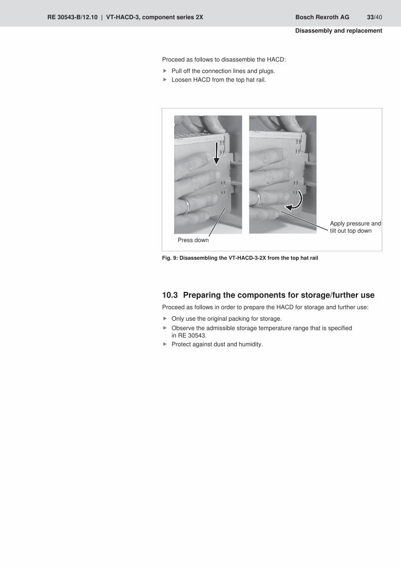
Proceed as follows to disassemble the HACD:
Pull off the connection lines and plugs. Loosen HACD from the top hat rail.
Press down
Apply pressure and tilt out top down
Disassembling the VT-HACD-3-2X from the top hat railFig. 9:
Preparing the components for storage/further use10.3 Proceed as follows in order to prepare the HACD for storage and further use:
Only use the original packing for storage. Observe the admissible storage temperature range that is specified in RE 30543.Protect against dust and humidity.

34/40 Bosch Rexroth AG VT-HACD-3, component series 2X | RE 30543-B/12.10
Disposal
Disposal11
11.1 Environmental protectionCareless disposal of the HACD and the packing material could lead to pollution of the environment.
Thus, dispose of the HACD and the packing material in accordance with the currently applicable national regulations in your country.
Return to Bosch Rexroth11.2 The products manufactured by us can be returned to us for disposal purposes at no costs. However, the precondition is that there are no spurious adherences or any other contamination. Hydraulic products have to be drained before being returned. Furthermore, there must be no inappropriate foreign matter or foreign bodies when products are returned.The products have to be sent free to the door to the following address:Bosch Rexroth AGService IndustriehydraulikBürgermeister-Dr.-Nebel-Straße 897816 Lohr am MainGermany
11.3 PackagingsUpon request, reusable systems can be used for regular deliveries. The materials for one-way packagings are mostly cardboard, wood, and styrofoam. These can be disposed of without any problems. Due to ecological reasons, one-way packagings should not be used for returning products to us.
Materials used11.4 Our products do not contain any hazardous materials that could be released during intended use. Normally, no adverse effects on human beings and on the environment have to be expected.The products essentially consist of:• Electronic components and assemblies
Recycling11.5 Due to the high share of metals the products can mostly be recycled. In order to achieve an ideal metal recovery, disassembly into individual assemblies is required. The metals contained in electric and electronic assemblies can be recovered by means of special separation procedures as well. If the products contain batteries or accumulators, these have to be removed before recycling and furnished to the battery recycling, if possible.
RE 30543-B/12.10 | VT-HACD-3, component series 2X Bosch Rexroth AG 35/40
Extension and conversion
Extension and conversion12
Optional accessories12.1 Denomination Material numberInterface cable set RS232, length 3 m R900776897USB RS232 converter R901066684Plug-in connector Type 6ES7972-0BA41-0XA0 for PROFIBUS DP R900050152CD with BODAC software SYS-HACD-BODAC-01 R900777335
Troubleshooting13
How to proceed for troubleshooting13.1 Always work systematically and focused, even when under time pressure. •Random and imprudent disassembly and readjustment of settings can, in the worst-case scenario, result in the inability to determine the original cause of the fault.First get a general idea of how your product works in conjunction with the entire •system.Try to find out whether the product has worked properly in conjunction with the •entire system before the error occurred first.Try to determine any changes of the entire system in which the product is •integrated:
Were there any changes to the product's operating conditions or operating –range?Were there any changes or repair works on the entire system (machine/ –system, electrics, control) or on the product?If yes: What were they?Was the product or machine used as intended? –How did the malfunction become apparent? –Try to get a clear idea of the cause of the fault. Directly ask the (machine) –operator.
For troubleshooting, use the “BODAC” and “WinView” diagnosis possibilities. •
If you should not be able to remedy an occurred error, please contact one of the addresses that you can find under www.boschrexroth.com or in the address directory in chapter 13.1.
36/40 Bosch Rexroth AG VT-HACD-3, component series 2X | RE 30543-B/12.10
Technical data
Technical data14 The technical data for the VT-HACD-3-2X digital control are available in the data sheet RE 30543.
Appendix15
Address directory15.1
Contact person for service15.1.1 Bosch Rexroth AGService IndustriehydraulikBgm.-Dr. Nebel-Str. 897816 Lohr am MainGermany
http://www.boschrexroth.com/serviceeMail: [email protected]
Contact person for support15.1.2 Bosch Rexroth AGZum Eisengießer 197816 Lohr am MainGermany
Phone +49 (93 52) 18-11 32Fax +49 (93 52) 18-33 63eMail: [email protected]

RE 30543-B/12.10 | VT-HACD-3, component series 2X Bosch Rexroth AG 37/40
Technical data

38/40 Bosch Rexroth AG VT-HACD-3, component series 2X | RE 30543-B/12.10
Technical data

RE 30543-B/12.10 | VT-HACD-3, component series 2X Bosch Rexroth AG 39/40
Technical data
Bosch Rexroth AG HydraulicsZum Eisengießer 197816 Lohr am Main, GermanyPhone +49 (0) 93 52 / 18 0Fax +49 (0) 93 52 / 18 23 58
Subject to change without noticePrinted in GermanyRE 30543-B/12.10