digital electronic over current relays - r&d … samwha eocr ltd.- ... limitation of...
TRANSCRIPT

EO
CR
CA
T_E
N
2008
Sam
wha
EO
CR
Ltd
.-All
right
s re
serv
ed.
Digital Electronic O
ver Current R
elays
Head Office6th floor, Jeil Bldg., 94-46, Youngdeungpo-Dong 7Ka, Youngdeungpo-Ku, Seoul, KoreaTel. 82 2 3473 2340 / Fax 82 2 3473 1159Iksan Plant574, Yongie-dong, Iksan-shi, Junbuk, KoreaTel. 82 63 835 5033 / Fax 82 63 835 4175www.eocr.com 10/2008
R&D Technology Pty Ltd Specialised Engineering ProductsNewcastle P: +61 2 4014 9000 F: + 61 2 4014 9099
Brisbane P: +61 7 3846 2644 F: + 61 7 3846 2346Wollongong P: +61 2 4285 9978 F: + 61 2 4285 9989Gloucester P: +61 2 6558 2986 F: + 61 2 4014 9099
Mackay P: +61 7 4952 3833 F: + 61 2 4014 9099E: [email protected]
website: www.rdtechnology.com.au

9
EOCR-i Series (with communication)Basic model : EOCR-i3DM (Z, S, 420) / iFDM (Z, S, 420)
Micro-Controller Unit based Real time processing / High precisionProtections : Over current, Under current, Phase loss, Phase reversal, Stall, Jam, Current imbalance,
Earth fault (i3MZ/iFMZ), Short circuit (i3MS/iFMS)Thermal protection / Inverse available up to 32Amps without external CTs.Auxiliary functions : Fail safe, Accumulated running hour, 3 fault records &
limitation of auto-restart. Analog output Communication : Modbus / RS-485Reinforced monitoring function : Monitoring distance up to 400M, 3 phase current display,
& Trip cause indication Bar graph indication of a load current to the current setting.Available application on single and 3 phase motor RoHS Compliancenormal protections are guaranteed even if PDM is disconnected.
General features
EOCR-i3DM Window type
EOCR-iFDM Bottom hole type EOCR-iFM420 Window type
EOCR-i3DM Terminal type EOCR-iFDM Terminal type
EOCR-i3DM Bottom hole type
10
EOCR-i Series (with communication)Basic model : EOCR-i3DM (Z, S, 420) / iFDM (Z, S, 420)
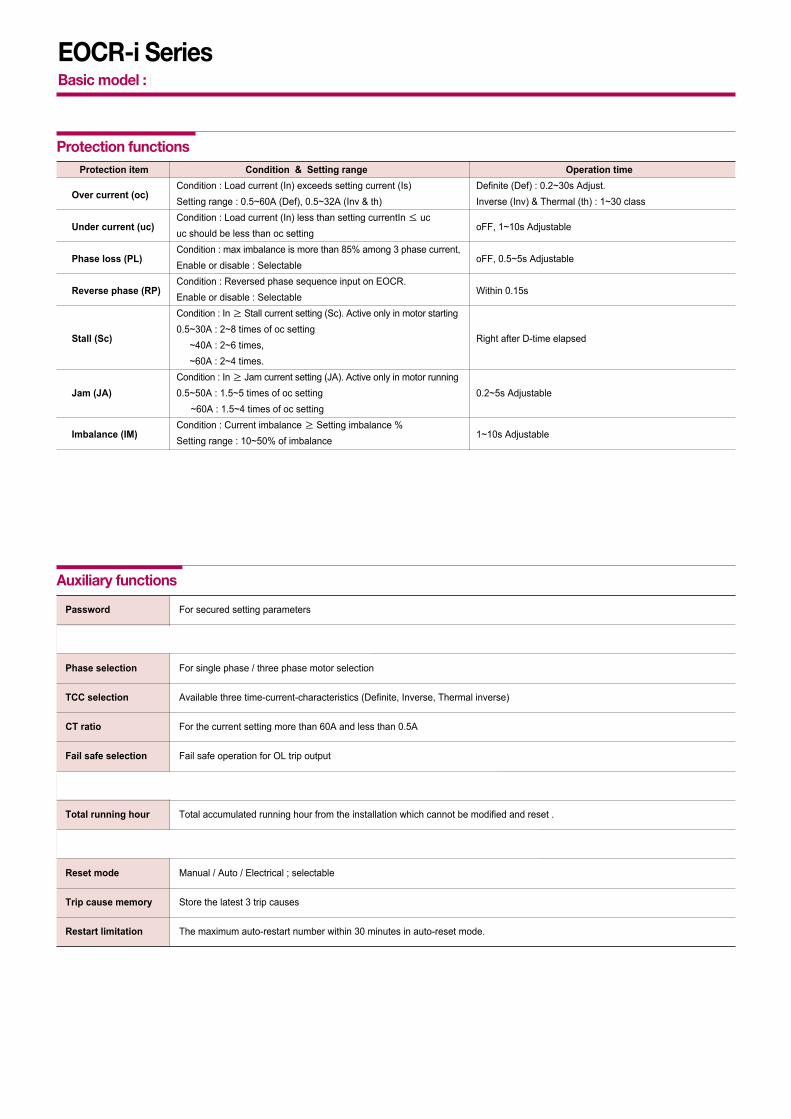
Protection item Condition & Setting range Operation time
Over current (oc)Condition : Load current (In) exceeds setting current (Is) Definite (Def) : 0.2~30s Adjust.Setting range : 0.5~60A (Def), 0.5~32A (Inv & th) Inverse (Inv) & Thermal (th) : 1~30 class
Under current (uc)Condition : Load current (In) less than setting currentIn ≤ uc
oFF, 1~10s Adjustableuc should be less than oc setting
Phase loss (PL)Condition : max imbalance is more than 85% among 3 phase current,
oFF, 0.5~5s AdjustableEnable or disable : Selectable
Reverse phase (RP)Condition : Reversed phase sequence input on EOCR.
Within 0.15sEnable or disable : SelectableCondition : In ≥ Stall current setting (Sc). Active only in motor starting
Stall (Sc)0.5~30A : 2~8 times of oc setting
Right after D-time elapsed~40A : 2~6 times, ~60A : 2~4 times.
Condition : In ≥ Jam current setting (JA). Active only in motor runningJam (JA) 0.5~50A : 1.5~5 times of oc setting 0.2~5s Adjustable
~60A : 1.5~4 times of oc setting
Imbalance (IM) Condition : Current imbalance ≥ Setting imbalance %
1~10s AdjustableSetting range : 10~50% of imbalance
Earth fault (EF)Condition : EF current (Ie) exceeds setting current (Ies) 0.05~5s AdjustableOFF, 0.03~10A -- i3MZ/iFMZ only -- Condition : SC current (Is) exceeds setting current (Iss)
0.05secShort circuit (SH) 0.5~10A : 2~22 times of oc setting,-- i3MS/iFMS only --
~20A : 2~11 times of oc setting
Protection functions
Password For secured setting parameters
Communication Monitoring currents and trip status by network
Phase selection For single phase / three phase motor selection
TCC selection Available three time-current-characteristics (Definite, Inverse, Thermal inverse)
CT ratio For the current setting more than 60A and less than 0.5A
Fail safe selection Fail safe operation for OL trip output
Pre alarm selection Pre alarm signaling by the 07-08 output contact -- i3MS/iFDM only --
Total running hour Total accumulated running hour from the installation which cannot be modified and reset .
Running hour Display or provied a time-out signal to the 07-08 output contact. -- i3MS/iFDM only --
Reset mode Manual / Auto / Electrical ; selectable
Trip cause memory Store the latest 3 trip causes
Restart limitation The maximum auto-restart number within 30 minutes in auto-reset mode.
Auxiliary functions

11
EOCR-i Series (with communication)Basic model : EOCR-i3DM (Z, S, 420) / iFDM (Z, S, 420)
Model iFM420Over current Rated setting range (A) Definite TCC : 0.5~60A. : use external CT higher than 60A
Inverse & th TCC : 0.5~32A. use external CT higher than32A
Under current Rated setting range (A) 0.5A ~ less than oc setting
Operating time characteristics Definite(Def) / Inverse(Inv) / Thermal(th)
Time setting Def D-time 0~200s
O-time 0.2~30s
Inv & th (cLS) 1~30 classes
GF delay time (Edt) 0~30s (i3MZ/iFMZ)GF O-time (Et) 0.05~10s (i3MZ/iFMZ)SH delay time (SHd) 0~30s (i3MS/iFMS)SH O-time Within 0.05s fixed (i3MS/iFMS) Auto-reset 0.5s~20min.
Reset mode Manual reset (H-r) / Electric reset (E-r) / Auto-reset (A-r)
Control power Voltage 100~240VAC/DC(85% ~110%, Free voltage), 24VAC/DC(±5%)
Frequency 50/60Hz
Power consumption Lower than 7VA
Output Capacity 3A/250VAC resistive.
Composition 1a1b : OC (i3DM/iFDM, i3MS/iFMS, i3M420/iFM420)1a : GR (i3MZ/iFMZ), or AL (i3DM/iFDM), or SH (i3MS/iFMS)
Display 7 segment LED 3 phase amps, Cause of trip, Setting parameters indication.
Bar-graph Load factor.
Communication Modbus/ RS-485
Mounting Panel mounting (i3DM/i3MZ/i3MS/i3M420)Flush mounting (iFDM/iFMZ/iFMS/iFM420)
Insulation Between case & Circuit Over DC500V 10MΩ
Dielectric strength Between case & Circuit 2kV, 50/60Hz, I Min.
Between contacts 1kV, 50/60Hz, I Min.
Between circuit 2kV, 50/60Hz, 1 Min
Electrostatic discharge (ESD) IEC61000-4-2 Level 3 : Air discharge : ±8KV, Contact discharge : ±6KV
Radiated disturbance IEC61000-4-3 Level 3 : 10V/m, 80 ~ 1000MHz
Conducted disturbance IEC61000-4-6 Level 3 : 10V,0.15~80MHz
EFT/Burst IEC61000-4-4 Level 3 : ±2KV, 1 Min
Surge IEC61000-4-5 Level 3 : 1.2 x 50µs, ±4KV (0°, 90°, 180°, 270°)
Emission CISPR11 Class A ( Conducted and radiated)
Environment Temperature Store -40°C ~ +85°C
Operation 20°C ~ +60°C
Humidity 30~85% RH ( Non-condensate)
Dimension Window type 70W × 74.5H × 83.8D
Bottom hole type 70W × 56.3H × 108.1D
Weight i3DM / i3MZ / i3MS / i3M420 iFM420Window type 330g 420g
Bottom hole type 370g 460g
Terminal type 370 + 120(PDM) = 490g 460 + 120(PDM) = 580g
Display (W/3M cable) - 125g
Power consumption Less than 7VA.
Specifications

65 70 75 80 85 90 95 100%
5 digit 7 segment LED display
Phase indicationLED
Phase indicationL1/L2/L3Bar graph
LED
Ampere(A)
Second(s)
12
EOCR-i Series (with communication)Basic model : EOCR-i3DM (Z, S, 420) / iFDM (Z, S, 420)
Front face
3 phase load currents (In) and a leakage current (i3MZ/iFMZ) are displayedevery 2 seconds in sequence.
Bar graphit shows the load factor to OC setting value by % % value = (running current/setting current) * 100%Min scale is 65%if the setting value is the rated motor current,
it shows the load factor of the motor.
Current DisplayShows the highest current among three phases for OC, Stall, Jam trips. Shows the lowest current among three phases for UC, UBShows the lost phase for PL.Shows the phase and the current during running.
Amp : Ampere. LED is on when a current display. x 10 : Shows the unit changed to 10 times.Sec : Second. LED is on when a time display.
7 segment LED display
Reset
Set / Store
Mode selectionswitch
NO output OL
NC output OL
CommunicationPower
AL/UL/TO
NO output OL
NC output OL
CommunicationPower
AL/UL/TO
7 segment LED Display
Mode selectionswitch
Reset
Set / Store

13
EOCR-i Series (with communication)Basic model : EOCR-i3DM (Z, S, 420) / iFDM (Z, S, 420)
L1 current display2sec
2sec
2sec 2sec
L2 current display
Rotate
L3 current displayEarth leakage current
3 phase digital ammeter function
※ Blocking display rotation can be done by pressing the SET button once during running. whenever press the SETbutton, the each phase current displays by turns. A fixed phase current display can be done by this.
※ Pressing the ESC button, it returns to the Auto current display rotation mode.
※ Fault history check : Pressing the ESC button more than 5sec, it displays the latest fault cause and the fault current orfault phase. Continuing to press DN button, you can see the current of L1(R), L2(S), L3(T), (GR) in turn. press the DNbutton again to check the previous fault continually. In the latest fault display, the 100% LED of bar graph lights on andtwo LEDs of 95%, 100% lights on for the second fault display, three LEDs of 90%, 95%, 100% lights on for the oldestfault display. When you press the ECS button in this mode, it returns to the normal current display mode. The oldestfault record is over written when the number of fault to record exceeds three.
Button Description
Navigate menus by pressing UP/DN button.
Select a parameter to change, then the parameter starts blinking.
Modify a parameter value by pressing UP/DN button.
Memorize the values in the relay by pressing SET button. blinking stops toshow it’s stored.Pressing ESC button, it returns to the current display. Without pressing ESC button, it returns to the load current display in 50sec automatically.
Buttons and setting sequence
i3MZ(S) / iFMZ(S)only
i3MZ / iFMZonly
i3MS / iFMSonly
i3M420 / iFM420 only
i3DM / iFDM only
i3DM / iFDM only
Setting sequence
(iXXZ Type only)

14
EOCR-i Series (with communication)Basic model : EOCR-i3DM (Z, S, 420) / iFDM (Z, S, 420)
No. Menu Parameter Description Default
Setting sequence and menu
Use password other than zero for secured settings. This feature enableslimitation of setting modification by unauthorized person. Zero value is usedfor disabling password checking.
“Ph:3Ph” mode for a 3 phase load, “Ph:1Ph” mode for a 1 phase load shouldbe selected. If you select the “Ph:1Ph”, RP, PL and Ub functions will bedisabled and not displayed in the menu mode
Time-current characteristic(TCC) setting. “dE” is for definite TCC, “In” is forinverse TCC, “th” is for thermal Inverse TCC. Refer to the time-currentcharacteristic curve. If tcc=no, only overcurrent protection is disabled
External CT ratio setting mode. This is applied to definite TCC; higher than 60Aand inverse TCC; higher than 32A. Set the primary value of the external CT.For example, 200:5 CT, setting is “ct:200”. For the low-range current “ct: 2t”is for 2 pass through, “ct: 5t” is for 5 pass through. Select “ct:non” in case of no externel CT and no loop.
Frequency setting mode. Select 50 or 60 based on the system fundamentalfrequency.
Selection of fail safe(No volt release) mode for overload trip output, OL.Refer to fail-safe operation
Enable or disable reverse phase detection
Threshold for over current protection . this value cannot be set below theunder current threshold (uc).
Motor starting delay, OC, UC, Stall, Jam, Ub are blocked during starting butPL, RP are not blocked. For “In” TCC mode, ,the cold curve is appled beforedt expires and, the hot curve is applied after dt expires.
(tcc:dE) ; the fault(over current) duration of definite overcurrent protection. (tcc:In) ; the trip class for inverse overcurrent protection(refer to TCC curve) (tcc:th) ; the thermal overload protection based on the thermal image by
load current (refer to TCC curve).
Threshold for under current protection. The setting should be higher thanno-load current of a motor. The current value cannot be set higher than OC.
Fault (under current) duration for the under current Operation. If the settingof “oFF” in the “uc” mode is selected, this menu is not displayed
Threshold for earth fault protection. The capacitance leakage current of themotor and cable should be taken into account for the setting. The thresholdvalue corresponds to the primary current of ZCT
Earth fault duration (Trip delay time) TCC is definite characteristic
Blocking time of Earth Fault detection during motor starting.OFF, 1~30s adjustable This timer is only active during motor starting.
Threshold for short circuit detection. This value is the multiples of the over current threshold (oc). The SC fault duration is fixed to 0.05 second.
1 Pass word
2 Selection of Phase No.
3 Operation curve
4 CT ratio
5 Frequency#1, #2
6 Fail safe
7 Reversed phase detection
8 Over current threshold
9 Start delay time
Over current
10 duration(Trip delay time /
Trip class )
11 Under current threshold
12 Under current duration(Trip delay time)
13 Earth fault
#1 (Ground fault) threshold
14 Earth fault#1 trip delay time
15 EF starting#1 delay
16 Short circuit#2 current threshold

15
EOCR-i Series (with communication)Basic model : EOCR-i3DM (Z, S, 420) / iFDM (Z, S, 420)
Blocking time of short circuit detection during motor starting.This timer is only active during motor starting.
Enable or disable phase loss(Single phasing) detection. If the “Ph:1Ph” isselected, this menu is not displayed.
Fault duration for phase loss operation. The setting range is 0.5~5 sec. if“PL:oFF” is selected, this menu is not displayed
Threshold for current imbalance operation. To disable the function, set to“oFF”, the setting range is 10~50%.Imbalance factor (%) = (Imax phase - Imin_phase) / Imax_phase x 100%
Imbalance fault duration (trip delay time) for current imbalance operation. The setting range is 1~10 seconds.
Threshold for locked rotor detection during motor starting. The value is themultiples of the over current threshold(oc). If the locked rotor condition isdetected, the trip relay operates in 0.5s after the “dt” expires.If dt=0, this function is disabled and not displayed in the menu.Setting range : oc=0.4~30A:2~8times, oc < 40A:2~6times, otherwise(oc<60A) : 2~4times, (with Ext. CT : 2~8times)
Threshold for locked rotor detection during motor running. The value is themultiples of the over current threshold (oc). Setting : oc=0.4~50A : 1.5~5times, otherwise (oc<60A) : 4times, (with Ext. CT : 15~5times)
Jam fault duration (trip delay time)Setting : 0.2~10 sec
Reference value for max analog output (20mA)If the load current is equal or greater than this value, analog output is fixed to 20mA
Threshold of Alert output, set by % of the over current threshold (oc). If theload current is higher than this value, alert output(07-08 contact) is energizedaccording to the setting of “ALo : XX”.
If the load current is detected, alert output(07-08 contact) is energized. Thealert threshold is no meaning for this operation.Refer to the alert operation pattern.
If the load current is higher than the alert threshold, alert output(07-08contact) repeats open for 1s and close for 1s (flickering), The flickering startsfrom the motor starting. Refer to the alert operation pattern.
If the load current is higher than the alert threshold, alert output(07-08 contact)is closed (holding) and remains closed until the load current decrease underthe alert threshold. The alert output is blocked during motor starting.Refer to the alert operation pattern.
If the accumulated running hour is more than the running hour threshold,the alert output repeats close for 1s and open for 1s.
The alert output is used only for under current protection. If this mode isselected, a trip by an under current fault is signaled through alert output(07-08), instead of overload trip output(95-96 or 97-98).
17 SC starting #2 delay
18 Phase loss
19 Phase loss time
20 Imbalance threshold
21 Imbalance fault duration
22 Stallthreshold
23 Jam threshold
24 Jam fault duration
25 420 Output#3 range
26 Alert#4
No. Menu Parameter Description Default
Setting sequence and menu

※ #1 => These are applied to i3MZ & iFMZ only.#2 => These are applied to i3MS & iFMS only.#3 => This is applied to i3M420 & iFM420 only.#4 => This is applied to i3DM & iFDM only.
※ Menusfrom password to reversed phase detection are not displayed during the motor running.
16
EOCR-i Series (with communication)Basic model : EOCR-i3DM (Z, S, 420) / iFDM (Z, S, 420)
Fault reset (Electrical reset) by a power cycle or by pressing the ESC button.
Fault reset (Hand reset) by only pressing the ESC button.
Fault reset (Auto Reset) by a auto-reset timer, Setting range of the timer : 0.5sec~20min. Also the fault can be reset by power cycle or by ESC button.The relay cannot be reset automatically when the relay is tripped by PhaseReversal(rP), Phase Loss(PL), Stalll(Sc) and Jam(JA)
The maximum auto-restart number during 30 minutes in auto-reset mode.The auto-restart counter (count) is stored in the non-volatile memory and iscleared by pressing ESC button when the counter(count) reaches the limitation.To disable limitation, select “oFF”. Setting range : oFF~5 times.
In this menu, toggle display, “-trh-” and the accumulated (time) value, isactivated (?)The accumulation starts from the installation and the user cannot clear theaccumulated value. This display unit is 1 hour.
In this menu, toggle display, “--rh-” and the accumulated value, is activated (?)The user can clear the accumulated value by selecting the running hourthreshold to “rh:oFF”. This display unit is 0.1 hour (6 minutes).By selecting “ALo:to”, the user can get the alert signal through alert output(07-08) when the accumulated value is more than the running hour threshold.
Threshold for alert output when the user selects “ALo:to”.The unit is 10 hours and this menu is not displayed when the motor isstarting or running. Setting range : 10~9990 hours, oFF
Modbus slave (ID) address.Range : 1 ~ 247.
Setting for communication speedRange : 1.2kbps, 2.4Kbps, 4.8Kbps, 9.6Kbps,19.2Kbps, 38.4Kbps.
Parity settingRange : odd, even, non.
Duration (communication. alarm trigger delay) for communication loss detection. Displays alarm when no new communication data is received for the duration.If “oFF” is selected, no monitoring for communication channel is activated.Setting range : 1~999 sec, oFF
When this menu activated, OL trip signal and enabled short or EF trip signalis generated when (3s+ot) expires.The display shows “End” when the test is done.By pressing ESC, returns to the load current display mode.This menu is not displayed when the motor is starting or running.Before (3s+ot) expires, pressing ESC or motor starting or running blocks thetest trip and return to the load current display. No parameter
This shows the end of test trip. Test result is stored in the fault record.
27 Reset
28 Restart limitation
29 Total running hour
30 Running hour
31 Running hour threshold
32 Communication
33 Test trip
34 End
No. Menu Parameter Description Default
Setting sequence and menu
read only
read only
Noparameter
Noparameter

17
EOCR-i Series (with communication)Basic model : EOCR-i3DM (Z, S, 420) / iFDM (Z, S, 420)
Trip indicationTrip Indication after trip with UP/ DN button pressing
Trip cause Indication Contents of indication L1 LED on L2 LED on L3 LED on
Over currentOC Trip caused by r(L1)-
phase current
Phase lossPhase Loss caused by r(L1)-
phase lost
Reversed phase Phase reversal trip
StallStall trip during motor starting
caused by s(L2)-phase curren
JamJam trip during motor running
caused by t(L3)-phase current
ImbalanceImbalance trip caused by t(L3)-
phase current
Under currentUnder current trip caused by
s(L2)-phase current
Earth fault Earth fault(Earth leakage) trip with
(i3MZ/iFMZ) Earth fault current indication
Short circuit Short Circuit trip caused by
(i3MS/iFMS) s(L2)-phase current
Limitation of In 30minutes, the number of auto-restar For emergency restart, manual reset by pressing ESC clears the restart auto-restart by auto-reset exceeds the setting counter to zero.
3 fault records including the trip cause and 3phase currents are stored in a non-volatile memory.When the motor is running or stopped, trip cause can be navigated by pressing ESC button over 5seconds
Trip cause indication and fault records
ALo “A” : Ampere relay function (The 07-08 output contact isclosed when a current is detected)
ALo “F” : Flickering ( When a current flows, the output contact isclosed and repeating the close and open on it in a highercurrent than the AL setting.)
ALo “H” : Holding (The output contact is closed in a higher currentthan the AL setting).
ALo “uc” : Applied to “uc” (under current protection) output contact.ALo “to” : When a running hour time is elapsed over the “rh” set
value, the output contact repeats the close - open.
ON
OFF
Alert operation pattern (i3DM & iFDM only)
Fail-safe operation
Aux ( )
Flicker ( )
Hold ( )
Fail-Safe A1-A2 not powered A1-A2 powered and A1-A2 poweredunder normal operation and Tripped
Starting Norma TripOperation
RunningStage
Higher than the presetAlert value
ALo Selection
18
EOCR-i Series (with communication)Basic model : EOCR-i3DM (Z, S, 420) / iFDM (Z, S, 420)
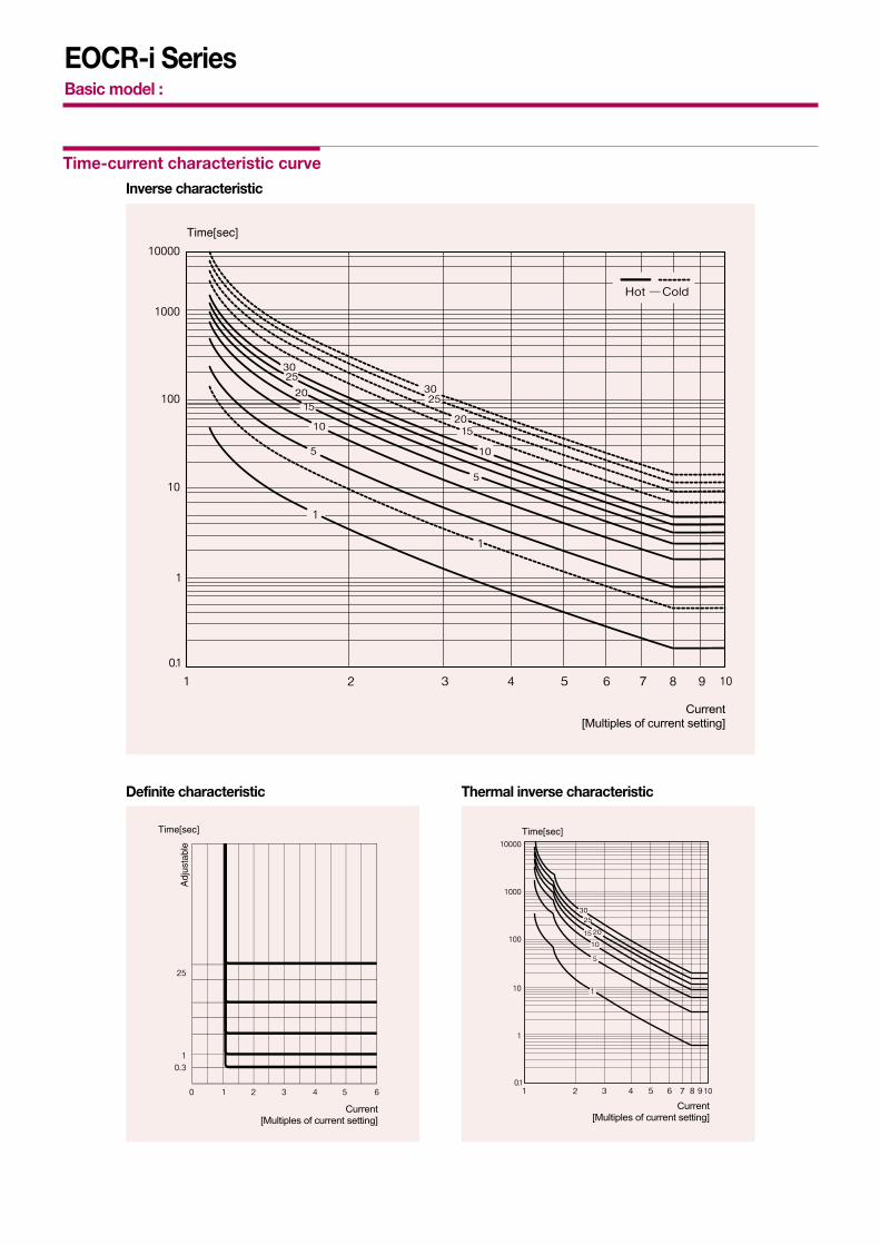
Time-current characteristic curve
Current[Multiples of current setting]
Current[Multiples of current setting]
Definite characteristic
Current[Multiples of current setting]
Thermal inverse characteristic
Inverse characteristic

19
EOCR-i Series (with communication)Basic model : EOCR-i3DM (Z, S, 420) / iFDM (Z, S, 420)
Setting range Number of pass through the CT hole External CT ratio CT Setting Remark
0.5 ~ 60A 1 No CT combination
0.25 ~ 3A 2 No CT combination
0.1 ~ 1.2A 5 No CT combination
0.5 ~ 32A 1 No CT combination Inverse TCC orthermal Inverse TCC
0.5 ~ 60A 1 No CT combination Definite TCC
10 ~100A 1 100 : 5 Definite or inverse (th)
20 ~200A 1 200 : 5 Definite or inverse (th)
30 ~ 300A 1 300 : 5 Definite or inverse (th)
40 ~ 400A 1 400 : 5 Definite or inverse (th)
50 ~ 500A 1 500 : 5 Definite or inverse (th)
60 ~ 600A 1 600 : 5 Definite or inverse (th)
70 ~ 700A 1 700 : 5 Definite or inverse (th)
80 ~ 800A 1 800 : 5 Definite or inverse (th)
Current setting range
Typical wiring schematic
L1 L2 L3
MC
A2 95 9707
A1 96 98
OL
08
MC Y
AL/ucto
Elec.Reset
Off
On
Trip
FuseTr.
MCCB
440,380/220
Fuse
L1 L2 L3
MC
A2 95 9707
A1 96 98
OLAL/ucto
08
MCY
Elec.Reset
Off
On
Trip
FuseTr.
MCCB
440,380/220
Fuse
L1 L3(L2;N)
MC
A2 95 9707
A1 96 98
OLAL/ucto
08
MCY
Elec.Reset
Off
On
Trip
FuseTr.
MCCB
440,380/220
Fuse
RS485Communication
RS485Communication
L1 L3(L2;N)
MC
A2 95 9707
A1 96 98
OLAL/ucto
08
MC Y
Elec.Reset
Off
On
Trip
FuseTr.
MCCB
440,380/220
Fuse
RS485Communication
RS485Communication
Typical wiring for EOCR-i3DM / iFDM ( 3 phase motor - window type)
Single phase motor (window type) Single phase motor (window type)
Bottomhole type
Bottomhole type

20
EOCR-i Series (with communication)Basic model : EOCR-i3DM (Z, S, 420) / iFDM (Z, S, 420)
Typical wiring schematic
L1 L2 L3
MC
A2 95 57 Z1
A1 96 58 Z2
OL GR
MC
Elec.Reset Off
On
MC
FuseTr.
MCCB
RS485Communication
440,380/220V
ZCT200:1.5
To: Z1 , Z2
SC MCCBshunt trip coil
MCCB
SC
Typical wiring for EOCR-i3MZ / iFMZ
L1 L2 L3
MC
A2 95 97
A1 96 98
OL
MCY
Elec.Reset
Off
On
Trip
FuseTr.
MCCB
RS485Communication
440,380/220V
4~20mA
Typical wiring for EOCR-i3M420 / iFM420
L1 L2 L3
MC
A2 95 9747
A1 96 98
OLSH
48
MC YSC
Elec.Reset Off
OnMCCB-a
Trip
FuseTr.
SC SC MCCB shunt coil
MCCB
RS485Communication
440,380/220V
Typical wiring for EOCR-i3MS / iFMS
Cabling for a three phase motor Cabling for a single phase motor

21
EOCR-i Series (with communication)Basic Model : EOCR-i3DM (Z, S, 420) / iFDM (Z, S, 420)
Control terminals
EOCR-i3DM/iFDM
Control power
AL/UL/TO NO output OL NC output
OL NO output
ModbusCommunication
A1 A2 07 08 95 96 97 98 V- D1 D0 S
OL OLAL / UL / TO COMM
EOCR-i3MZ/iFMZ (“A” type)
EOCR-i3MZ/iFMZ (“C” type)
EOCR-i3MZ/iFMZ (“D” type)
Control power
OL NO output EF NO output
ZCT input
A1 A2 97 98 57 58 Z1 Z2 V- D1 D0 S
OL GR COMM
A1 A2 95 96 57 58 Z1 Z2 V- D1 D0 S
OL GR COMM
A1 A2 95 96 97 98 Z1 Z2 V- D1 D0 S
OL / GR COMM
ZCT
ZCT
ZCT
Control power
OL/EF NO/NC common output ZCT input
A1 A2 97 98 57 58 Z1 Z2 V- D1 D0 S
OL GR COMM
A1 A2 95 96 57 58 Z1 Z2 V- D1 D0 S
OL GR COMM
A1 A2 95 96 97 98 Z1 Z2 V- D1 D0 S
OL / GR COMM
ZCT
ZCT
ZCT
Control power
OL NC output EF NO output
ZCT input
A1 A2 97 98 57 58 Z1 Z2 V- D1 D0 S
OL GR COMM
A1 A2 95 96 57 58 Z1 Z2 V- D1 D0 S
OL GR COMM
A1 A2 95 96 97 98 Z1 Z2 V- D1 D0 S
OL / GR COMM
ZCT
ZCT
ZCT
EOCR-iFM420
Control power
OL NC output OL NO output
4~20mA output
A1 A2 95 96 97 98 + V- D1 D0 S
OL 4~20mAOL
EOCR-i3MS/iFMS
Control power
SH NO output OL NC output
OL NO output
A1 A2 47 48 95 96 97 98 V- D1 D0 S
OL OLSH COMM
ModbusCommunication
ModbusCommunication
ModbusCommunication
ModbusCommunication
ModbusCommunication

23
EOCR-i Series (with communication)Basic model : EOCR-i3DM (Z, S, 420) / iFDM (Z, S, 420)
Dimension of iFXX
∅65
∅64
28.1
13.4
72
72
102.4
3-∅12
9583.8
70
∅4.5
82
22.522.5
56.3 74
.5
3-∅12
126.7108.1
70
21.4
21.4
56.3
8295
∅4.5
126.7108.1
53.3
91.3
45.321.421.4
6-M4
70
21.421.46-M4
70
82
∅4.5
95
PANEL & DIN RAIL TYPE MOUNTING HOLE SIZE
PANEL & DIN RAIL TYPE MOUNTING HOLE SIZE
PANEL & DIN RAIL TYPE MOUNTING HOLE SIZE
MOUNTING HOLE SIZE
Window typeEOCR-iFDMEOCR-iFMZ
EOCR-iFM420EOCR-iFMS
Bottom hole typeEOCR-iFDMEOCR-iFMZ
EOCR-iFM420EOCR-iFMS
Terminal typeEOCR-iFDMEOCR-iFMZ
EOCR-iFM420EOCR-iFMS
DisplayEOCR-PDM

25
EOCR-i Series (with communication)Basic model : EOCR-i3DM (Z, S, 420) / iFDM (Z, S, 420)
Ordering
EOCR-PDMQDisplay
Cable connector
Connector type RJ4500H 0.5 m001 1 m
Cable length 01H 1.5 m002 2 m003 3 m
Others Custom made
RJ45 001CABLE - -
Square 3 CT
H1-100-C Square 3CT 100:5HH-150-C Square 3CT 150:5
CT ratio H2-200-C Square 3CT 200:5H3-300-C Square 3CT 300:5H4-400-C Square 3CT 400:5
H1 1003CT - - - C
SR-CT
S1 100 100:5SH 150 150:5
CT ratio S2 200 200:5S3 300 300:5S4 400 400:5
100SR-3CT -
ZCT
035 35mm Inner-diameter 080 80mm
120 120mm
035ZCT -

45
Technical information
Option-1. Looping (Protect smaller current by looping option)
Some motor size may require one-third or one-fourth of particular EOCR currentrange. These installations can be accommodated by looping the motor wire 2 or3 times through the integral current transformers of the EOCR. This reduces thenumber and type of relays inventoried for spare purposes. Each additional loopwill increase the current measured as indicated by the following chart.
Ordering option - 05 type of each model fitted to an external current transformercan achieve higher ampere ranges. (EOCR-3DM/3MZ/3M420/FDM/FMZ/FM420)
Option-2. External current transformer option(Ext. CT option protect bigger current)
05 Type
Looping Option
Current settingrange (A)
0.5 ~ 6 0.25 ~ 3 0.17 ~ 2
0.12 ~ 1.50.10 ~ 1.2
No. of passing (#)12345
No. of loops(#)
0 …1 …
2 34
05 type60 type
Ext. CT option
DIP SWsetting
056005050505
Current settingrange (A)0.5 ~ 10 5.0 ~ 60 10 ~ 12015 ~ 18020 ~ 24030 ~ 360
Current ratio of Ext. CT
NILNIL
100 : 5150 : 5200 : 5300 : 5
EOCR type table for 3 phase motor
Short-circuit current setting (Isc)
Starting current
Current
Current setting (Is)
Starting
In O-time mode, EOCR does not make a trip assensing current (In) over preset over-current (Is) is notkept during preset o-time
In case Short-circuit current is over thanpreset trip value, it trips at 0.05sec
(i3MS, iFMS)
Motor tripped by EOCR
Starting time (dt)
Normal running status
TimeTripped status
O-TIME:When sensing currentexceeds the preset currentrange.EOCR trip after O-time
D-TIME:In starting period, it senses 5 to 8 timeof rated current but delays O-time tripmode due to preset D-time which allows normal running without trip during starting period.
Motor tripped by EOCR.Reset the motor after removing the cause of motor failure.
Preset currentsetting exceed
Preset currentsetting exceed
Alert signal output
Preset alertsetting exceed
Alert output signal comes out after waiting1sec as soon as running current exceeds presetAlert setting value. It checks the increment ofload in advance before a trip happens
Overload
Alert setting (As)
Normal running current (As)
1sec
EOCR setting platform / Motor running current
Single pass Double pass
EOCR typeand CT
0560
100:5150:5200:5300:5400:5500:5
0.5~10 5~60
10~12015~18020~24030~36040~48050~600
0.751122303775
- -
115304050
100- -
1.522375575
132190220
2305075
100175250300
4.84893
125160310440572
4.24984
121163263376424
3.64273
105141227325390
416507095
300- -
4255070
120240400
-
4255070
120240400400
Current settingrange
(Adjustable) [A]
Capacity of 3 phase motorAC220 [V] AC380/440 [V]
kW HP kW HP
Motor current [A]
AC220V AC380V AC440V
Cable size IEC []
AC220V AC380V AC440V

46
Technical information
Setting tips in definite TCC mode1. Over current threshold (OC) : Set the OC at the rating current of a motor. To protect
machine together, it is recommended to set at110~120% of the actual normal operating current.
2. Starting delay time (D-time) : Set an expected start-up time to reach the normal speedof load. If you do not know it, set to 15sec at first andstart-up the motor to measure the time to reach thenormal operation speed by monitoring the displayedcurrent and then change the time into 2 sec longer thanthe time measured. For a Y-D start, it ’s better to set timelonger than the preset time of the timer by 2secminimum normally.
3. Operation time (O-time) : Set the trip delay time which activates and counts downunder a fault condition.
Setting tips in inverse or thermal inverse TCC mode1. Over current (OC) : Set the OC at the rating current of a motor.
2. Starting delay time (D-time) : Usually, set D-time to zero. With zero D-time, the coldcurve is applied before the load current cross down theOC, and then the hot curve is applied.If the start-up time is long and fast trip is required duringmotor running, set D-time to start-up time or longer. Inthis case, over current protection is blocked during thestart-up, and the hot curve is applied when D-timeexpires.Since thermal inverse has no relation with D-time, set D-time to zero when the thermal inverse is selected.
3. Operation time (O-time) : It has 30 curves of 1~30 which conforms to theIEC947-4-1 standard. The class value approximately equals to the time to tripunder 550% of overload by the cold curve characteristic.
Over current and time setting tips.

47
EOCR Setting Guide
This is a setting guide and advice for user’s reference only . Conditions to be checked for the normal operation of EOCR .1. Check the status of correct settings by pressing the UP/DN button in
sequence.2. When you enter the menu and wait for 3 sec, it starts
countdown during the O-time setting. and displaywith a trip to the output . This means EOCR is operating well.
3. Check all the sequence wiring if it is safe and correct .4. After completion of the motor starting, check if the current display is
fine, When the %LED in the bar graph doesn ’t show, it needs tocheck if the operation current is too lower than the Oc setting valueby 65% and on the contrary, the %LED shows 100% (red LED lightson), It is advised to check the Oc setting if the re-adjustment isnecessary.
5. If the motor starting isn ’t completed but EOCR operates, refer to theTroubleshooting guide first and contact customer care center if thetrouble isn’t cleared.
Basic model (3DM / FDM)
Password input is necessary to chage the setting value ofEOCR, if a password is memorized except 000.If the password is set to 000, no password input is necessaryin “000” to enter the setting change mode. Please takecaution not to forget the password.No password function isprovided in 3DM2/FDM2, 3MZ2/FMZ2.
The default setting is a 3phase motor. The setting changeto is necessary for 1 phase motor.
Time current characteristic (TCC). the defaut setting istcc : dE (definite TCC).
The default setting is “non”, setting value is the primarycurrent with an external CT combination in this mode.( Ex: in case of 200; 5, the setting is 200 )
If the control power or EOCR itself has a problem, themotor stops with the output relay trip in the “FS: on” mode.The default setting is.
For the application which motor rotation direction isimportant , “rP: on” should be set .“rP:oFF” setting doesn’t make a problem after completionof the installation for the permanent stable application.The default setting is “rP:oFF”.
It is recommended for “oc” to set at the rating current ofmotor. Default setting is oc:5.0A .
It means a starting delay time setting for a motor start upduration from the start of motor to the normal runningcurrent. The start up duration depends on the inertia ofload. Therefore, it is recommended to set the time after
measuring the time and current by EOCR with the initialset of D-time at 20 sec. For a Star-delta start, the longertime by 2sec than the setting of Star-delta timer isrecommended. Default setting is 5 sec.
It means the overcurrent trip time in definite TCC, whenmotor operating current (In) exceeds over current setting(Is) during the ot setting time, EOCR trips. Default settingis 5 sec. The advantage of definite TCC is that user is ableto set accurate time and current and lead a mechanicalprotection of load together with motor protection.
This is a trip class(curve) setting in Inverse TCC orThermal inverse TCC. The trip time changes according tothe operating current inverse proportionally. Thermalinverse TCC reflects the Heat capacity of motor based onthe current measurement.
It means under current (Dry Run) protection, If a levelswitch has a problem in a submersible pump, It backs upthe level switch function from no water running of pumpand protect the motor from overheating. For themachinery running with a belt (including conveyer), Itcandetect a broken belt. The current setting should behigher than rating no load current of motor for this function.The default setting is “oFF” .
It is “uc” trip delay time setting . If you don ’t set the “uc”function (uc:oFF), “ut” setting doesn’t appear at the menu.
This memu is to determine “enable/disable” of PL (Phaseloss) funnction. If you set “Ph:1Ph” at the power phaseselection menu for a single phase power supply line, thismenu doesn’t appear automatically.
It is trip delay time setting for PL. The default setting is 2sec. For single phase power line setting, it doesn ’t appearat the munu.
EOCR calculates the unbalance rate among threephase currents. It trips after “Ubt” setting time under aunbalanced condition. The default setting is “oFF”.
Locked Rotor protection during starting up a motor (Stall).If a rotor of motor is locked during starting and keep thecurrent at higher than the “Sc” setting during D-time,EOCR trips in 0.5sec after D-time. The default setting is“Sc: 4”.The setting value is a multiple of “oc” setting value. Thisfunction operates under the Definite TCC condition. It is disabled under the Inverse TCC setting generally. Butif you set D-time greater than zero in Inverse setting, Stalloperates when d-time expires.
EOCR Setting Guide

48
EOCR Setting Guide
Locked rotor protection during normal running of motor(Jam). It is used to prevent a problem caused by rapidload increae. The setting value is a multiple of “oc” settingvalue. The trip delay time setting range is 0.2~10 sec.
Alarm setting by % of the overcurrent threshold (oc). Theoutput contact 07-08 makes a signal of A,F,H according tothe ALo setting.
Reset type setting mode. Reset method shows below.
Electrical Reset . EOCR resets by power cycleof control power or ESC button. It can be usedfor a remote reset which enables EOCR to resetfrom a remote site.
Hand Reset (Manual Reset). EOCR can bereset by ESC button only.
Auto Reset . The time setting range is up to 20minutes (20n). The auto reset number. of timesis connected to the restart limitation settingmenu. If the number of restrat over the restartlimitation number. in the “rn” setting menuduring 30 minutes, EOCR doesn ’t resetanymore.
Restart limitation number. It prevent a motor from aburning fail caused by many restarts during 30 minutes.In case an emergency restart is necessary, put the settingat “OFF” This function activates in Auto-Reset mode only.
Modbus slave (ID) address. It can be set at No. 1 ~ 247.
Setting for communication speed. Select one among1.2kbps, 2.4kbps, 4.8kbps, 9.6kbps,19.2kbps, 38.4kbps.
Parity setting. Select one among odd, even, non. evenparity is displayed as “Eun”.
Communication loss checking menu. If EOCR does notreceive a data frame during “Lt” setting time, it displays anerror message. The setting range is OFF, 1~999 sec.
Total running hour. Time accumulation starts if there is aminimum sensing current in the line up to 99,999 hours.User can check it anytime but not allowed to erase it.Display unit is 1 hour.
Running hour which user can set and erase the settingvalue. If you set the Alert output type at the “ALo: to”, theoutput contact 07-08 repeats close and open to give asignal after the preset accumlated time elapsed.
Self EOCR Check. If you push SET button in this menu,EOCR count time up 3sec and “ot” setting time anddisplays “End” with the output contact trip. This meansEOCR is operating well. This function is blocked duringmotor running.
Additional menu (i3MS/iFMS)
Short Circuit protection. Setting value is a multiple of “oc”set value. Default setting is 10 times of “oc” setting.
Short Circuit trip delay time during motor starting toprevent a trip caused by starting current. ”OFF” setting ispossible .
Additional Menu (i3MZ/iFMZ, 3MZ2/FMZ2)
Earth leakage protection current setting. The defaultsetting is 0.5A. Minimum setting value is recommeded, ifthere is no leakage current in the motor by the currentdisplay. If the display shows a leakage current more than50mA, user must check the insulation of motor and line. Inthe case of installing EOCR at the secondary side ofInverter, it’s better to take care of EOCR opreration errordue to harmonics of Inverter.
Earth leakage trip time. The default setting is “0.05sec”. It is recommended to set the faster time and lower currentthan the earth fault protection relay in the upper powersystem.
Earth leakage trip delay time during motor starting toprevent a trip caused by a stray current and harmonics ofthe starting current in motor.
Additional menu (i3M420/iFM420)
Current range setting menu of 4~20mA analog outputsignal. The setting value corresponds to the max analogoutput (20mA). The setting value can be madeindependently from “oc” setting .Analog output current formula :
Where, CTR is the parameter for CT, i.e. in case of CI :non, it is 1. I is the measured average lond current.If the load current is equal or greater than this value,analog output is fixed to 20mA . For the current lower thanminimun sensing current of EOCR(0.4A), the analogoutput signal gives 4 mA .
EOCR Setting Guide
mA = Ⅰ × 16 + 4rS

49
Troubleshooting Guide
1. Reversed phase :It trips instantly within 0.15sec from the motor starting. Check thephase sequence and cable direction of the power line going to the motor first. The sequence of EOCR internal CT isA(L1), B(L2), C(L3) from the left side. If the passing order of motorline to the EOCR doesn’t coincide with the order of EOCR CT or notsame all the direction of cables, It trips by RP. In this case, changethe order of the two cables among three. When the sequence ofcables to the motor changes in the downstrenm side of EOCR ,EOCR isn’t able to check the RP. The sequence of cables should becoincided from the power mains to the motor. If the RP is not anindispensable function or only necessary for the first installation andfixed in the site, The setting is recommended for normaloperation.
2. Overcurrent : Overcurrent trip displays the biggest current among three phasesand the small LED in the left side shows the phase.If the trip current is lower than the rating current of motor, check the“oc” setting if it is too low. The recommended “oc” setting is110%~120% of actual running current in the definite TCC.
3. Stall : When the starting current doesn ’t go down below the “Sc” settingduring D-time. EOCR trips by Stall within 0.5se when D-time expires. Check the status of load and D-time, whether the D-time is too shortor not. The recommended D-time is longer by 1sec than a time thatthe motor come to the normal running current .
4. Phase loss : The small LED in the left side lights up and designates which phaseis lost in the display like as PL - r, PL - S, PL - t, To check the PL status, put the PL trip time at the maximum andmeasure the lost phase current by a clamp meter after a test start,whether there is a current in the motor line or not. The minimumoperating current (min setting current) of motor sensed by EOCRcan make trip due to hunting current. Need to check load operationcondition of the application in this case. If the clamp meter shows anormal current in the lost phase line, Check the EOCR status.
5. Unable to starting :Even though the sequence wiring is O.K. If the motor is not able tobe started with no magnetic contactor energized, Check the FailSafe menu of with the output contact status(NO, NC) of EOCR .
6. Undercurrent :Undercurrent trip displays the lowest current among three phasesand the small LED in the left side shows the phase.The example shows the sensing current of 1.6A in L2(S) phase. Forthe heater line broken detection in a heater application. EOCR tripsby undercurrent according to the setting in delta connection, andtrips by phase loss in Star connection.
7. Current unbalance : Ideally, the motor currents of three phases are balanced. If a currentunbalance is high, the motor need to be checked.The formula is as follows.Unbalance factor (%) = (Imax phase - Imin_phase) / Imax_phase× 100%
8. Jam : Rapid overload protection during motor running, Check the loadwhich cause impacts it. If you find no problem in the load and motor,try to chage the setting value higher of the time and current to beappropriate for the application.
9. Unable to reset : If you cannot reset EOCR by control power interruption, Check thereset type setting first. In the setting of User can reset EOCR by ECS button only. If you want to resetEOCR by both control power cycle and ECS button, Put the settingat
Troubleshooting Guide
50
Communication setting valuePlease set the Modbus communication parameters by PCON or HMI for the communication. Slave addressBaud rateParityCommunication loss timeout
Slave addressThe EOCR has slave addresses from 1 to 247. The factory default setting is 1.
Baud rateThe Communication speed provided is like below.1.2kbps2.4kbps4.8kbps9.6kbps19.2kbps38.4kbpsThe factory default setting is 19.2kbps
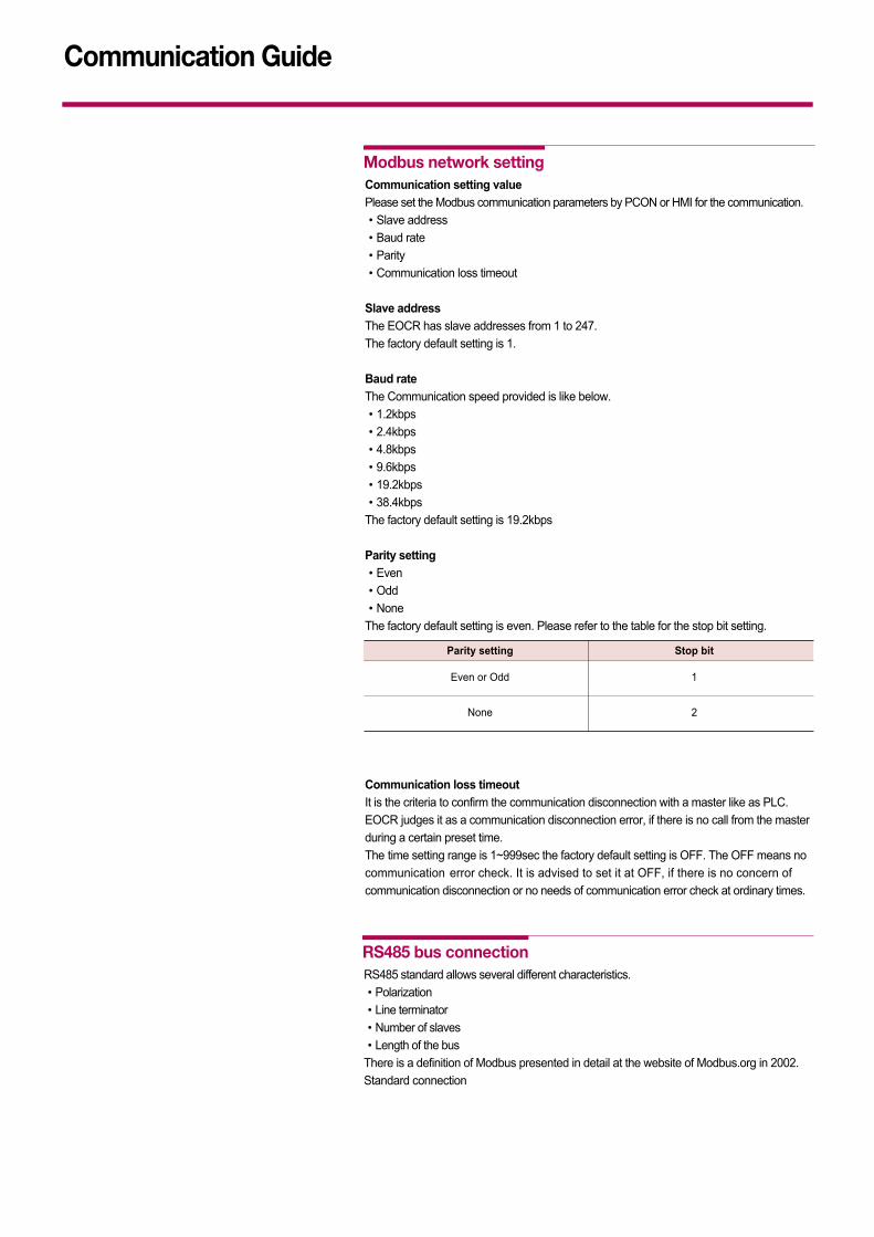
Parity settingEvenOddNoneThe factory default setting is even. Please refer to the table for the stop bit setting.
Communication loss timeoutIt is the criteria to confirm the communication disconnection with a master like as PLC. EOCR judges it as a communication disconnection error, if there is no call from the masterduring a certain preset time. The time setting range is 1~999sec the factory default setting is OFF. The OFF means nocommunication error check. It is advised to set it at OFF, if there is no concern ofcommunication disconnection or no needs of communication error check at ordinary times.
Modbus network setting
Parity setting Stop bit
Even or Odd 1
None 2
RS485 bus connectionRS485 standard allows several different characteristics.PolarizationLine terminatorNumber of slavesLength of the busThere is a definition of Modbus presented in detail at the website of Modbus.org in 2002.Standard connection
Communication Guide

5151
Communication Guide
The standard connection conforms to the Modbus specifications, sepecially 2 wiremultidrop serial bus diagram, presented at the website of Modbus.org in 2002(Modbus_over_serial_line_V1.pdf, Nov.2002). Simple wiring diagram is like below.
The characteristics is like below in case of a direct connection to the bus.
Items Contents
Type of trunk cable single, shielded, twisted pair cable. Min 3rd cable
Maximum length of the bus 1000m (3,2181 ft) (at 19.2kbps)
Maximum number of32 stations (31 slaves)
stations without repeater20m (66ft, at 1 tapoff)
Maximum length of tapoffs 40m (131ft, divided by tapoff no.in Multi-Junction Box)
450 - 650Ω Pullup resistor, 5V basis450 - 650Ω Pulldown resistor,
Bus polarization Recommend the polarization to Master at Common. There is no polarization atRS485 of EOCR .
Line terminator 120Ω Resistor, + /- 5%
Common polarityYES (connect 1 protection ground minimum
to the bus)
Standard connection

52
Communication Guide
Bus connection through a SCA type junction box
1. Master (PLC, PC or communication module)2. Modbus cable (It is different according to the master side or a master having polarization combined to the other part of Bus) 3. Junction box4. Modbus cable5. Line terminators : 120Ω - 0.25W
Please use a cable with 2pair shieded twisted conductors for Interface protection. It is adviced to isolate the Modbus cable 30cm(11.8in) at least from a power cable. If necessary, intersect the Modbus cable to a power cable perpendicularly. Refer to the diagram in the left side for the line terminator wiring.