digital power meter •digital power analyzer •power quality
TRANSCRIPT
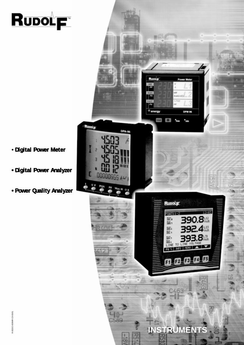
• Digital Power MeterDigital Power MeterDigital Power MeterDigital Power MeterDigital Power Meter
••••• Digital Power AnalyzerDigital Power AnalyzerDigital Power AnalyzerDigital Power AnalyzerDigital Power Analyzer
••••• Power Quality AnalyzerPower Quality AnalyzerPower Quality AnalyzerPower Quality AnalyzerPower Quality Analyzer
R-0
ED
CI-
000M
R-C
0-05
/01
INSTRUMENTS

Bridex Singapore Pte Ltd was founded in 1973 as a manufacturer of instruments transformer for
the Asian market. We are the first local electrical switchgear components manufacturer that
launches our own Asian identity – Rudolf.
Today we aim to become a knowledge-based, technology driven engineering organization,
with emphasis on providing solution for electrical distribution and control, in area of instruments,
distribution & protection and standard components. With our present headquarter in Singapore
and subsidiaries that are located in Philippines, China and Australia, we are well equipped to
service both local and Asia-Pacific countries.
Product Introduction
What are the reasons behind an increasing trend toward the use of power meter and power
analyzer? To replace the conventional metering using analogue meter? We take reasons better
than this. With just one product, we achieve consolidated measurement, energy metering,
alarm monitoring, possibility for remote communication, the possibility for control and command
and the possibility for data logging function via sole proprietor software. These possibilities
allow the user to obtain and manage information thereby providing the user with the capability
to control cost, improve power quality and participate in control system (BMS)
These functions can be achieved by your selection of any of RUDOLF:
R-DPM96 - Digital Power Meter
R-DPA96 - Digital Power Analyzer
R-PQA144 - Power Quality Analyzer
R-DPA96R-DPM96 R-PQA144
Corporate Introduction
1
Digital Power Meter - DPM96
2
Basic Features
OTHER FEATURES• Compact-size (96 x 96 mm), panel-mounting power meter.• True R.M.S. measuring system.• Instantaneous, maximum and minimum values of each measured parameter.• Energy measurement (indication through a lighting LED)• RS-485 type communication to a PC• Harmonic distortion measurement (THD-V & THD-A ).• Active & Reactive Metering.• Maximum 2 user-programmable pulse/alarm outputs are available in DPM 96 power meter to transmit active and reactive
energy information / user-defined threshold overshoots.• Energy Measurement - designed for energy management applications, the DPM 96 power meter can transmit all
information required for electricity billing such as load curves in active or reactive power, active and reactiveenergy to a computer.
• RS 485 or RS 232 Communication - The DPM 96 power meter can be equipped with an RS 485 output or RS 232 output(optional) ModBus RTU protocols to transmit all electrical information in digital form to a computer, PLC, or evena display repeater.
• Software - The DPM96 (model with RS 485 port / RS 232 port) can be used in conjunction with its proprietary software,Easycomm Plus for remote monitoring and display of its electrical parameters, remote modification of its setting, datalogging, to record its designated electrical parameter (programmable time interval, minimum 1 sec).
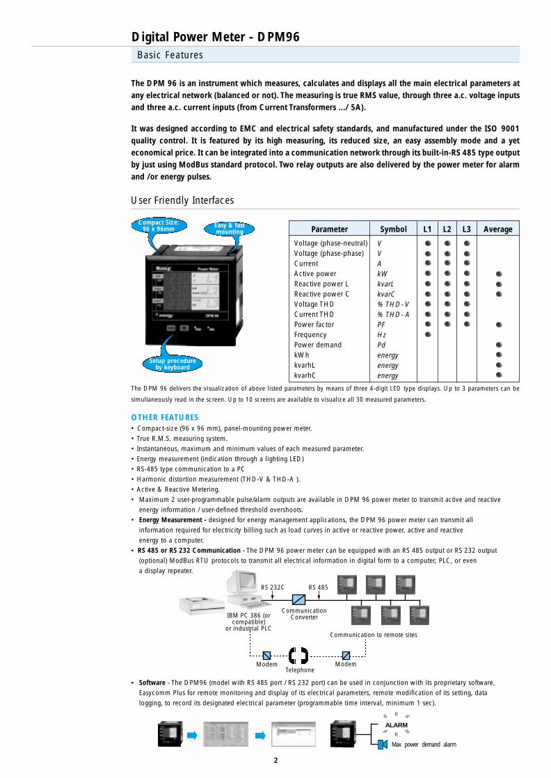
The DPM 96 is an instrument which measures, calculates and displays all the main electrical parameters atany electrical network (balanced or not). The measuring is true RMS value, through three a.c. voltage inputsand three a.c. current inputs (from Current Transformers .../ 5A).
It was designed according to EMC and electrical safety standards, and manufactured under the ISO 9001quality control. It is featured by its high measuring, its reduced size, an easy assembly mode and a yeteconomical price. It can be integrated into a communication network through its built-in-RS 485 type outputby just using ModBus standard protocol. Two relay outputs are also delivered by the power meter for alarmand /or energy pulses.
User Friendly Interfaces
Voltage (phase-neutral)Voltage (phase-phase)CurrentActive powerReactive power LReactive power CVoltage THDCurrent THDPower factorFrequencyPower demandkWhkvarhLkvarhC
VVAkWkvarLkvarC% THD- V% THD- APFHzPdenergyenergyenergy
Parameter Symbol L1 L2 L3 Average
The DPM 96 delivers the visualization of above listed parameters by means of three 4-digit LED type displays. Up to 3 parameters can be
simultaneously read in the screen. Up to 10 screens are available to visualize all 30 measured parameters.
Setup procedureby keyboard
Easy & fastmounting
Compact Size:96 x 96mm
Communication to remote sites
RS 232C RS 485
CommunicationConverterIBM PC 386 (or
compatible)or industrial PLC
ModemTelephone
Modem
ALARM
Max power demand alarm
Digital Power Meter - DPM96
3
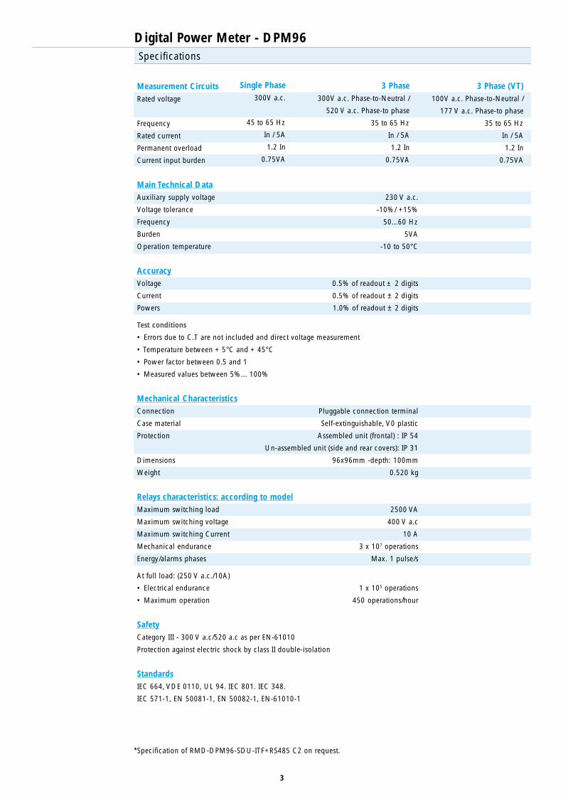
Measurement CircuitsRated voltage
Frequency
Rated current
Permanent overload
Current input burden
Main Technical DataAuxiliary supply voltage 230 V a.c.
Voltage tolerance -10%/ +15%
Frequency 50...60 Hz
Burden 5VA
Operation temperature -10 to 50°C
AccuracyVoltage 0.5% of readout ± 2 digits
Current 0.5% of readout ± 2 digits
Powers 1.0% of readout ± 2 digits
Test conditions
• Errors due to C.T are not included and direct voltage measurement
• Temperature between + 5°C and + 45°C
• Power factor between 0.5 and 1
• Measured values between 5%... 100%
Mechanical CharacteristicsConnection Pluggable connection terminal
Case material Self-extinguishable, V0 plastic
Protection Assembled unit (frontal) : IP 54
Un-assembled unit (side and rear covers): IP 31
Dimensions 96x96mm -depth: 100mm
Weight 0.520 kg
Relays characteristics: according to modelMaximum switching load 2500 VA
Maximum switching voltage 400 V a.c
Maximum switching Current 10 A
Mechanical endurance 3 x 10⁷ operations
Energy/alarms phases Max. 1 pulse/s
At full load: (250 V a.c./10A)
• Electrical endurance 1 x 10⁵ operations
• Maximum operation 450 operations/hour
SafetyCategory III - 300 V a.c/520 a.c as per EN-61010
Protection against electric shock by class II double-isolation
StandardsIEC 664, VDE 0110, UL 94. IEC 801. IEC 348.
IEC 571-1, EN 50081-1, EN 50082-1, EN-61010-1
Specifications
Single Phase300V a.c.
45 to 65 Hz
In / 5A
1.2 In
0.75VA
3 Phase 300V a.c. Phase-to-Neutral /
520 V a.c. Phase-to phase
35 to 65 Hz
In / 5A
1.2 In
0.75VA
*Specification of RMD-DPM96-SDU-ITF+RS485 C2 on request.
3 Phase (VT) 100V a.c. Phase-to-Neutral /
177 V a.c. Phase-to phase
35 to 65 Hz
In / 5A
1.2 In
0.75VA
Digital Power Meter - DPM96
4
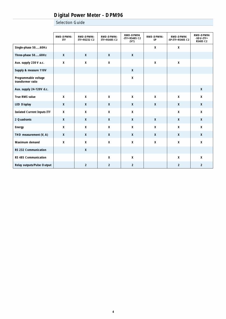
Selection Guide
Single-phase 50.....60Hz
Three-phase 50.....60Hz
Aux. supply 230 V a.c.
Supply & measure 110V
Programmable voltagetransformer ratio
Aux. supply 24-120V d.c.
True RMS value
LED Display
Isolated Current Inputs ITF
2 Quadrants
Energy
THD measurement (V, A)
Maximum demand
RS 232 Communication
RS 485 Communication
Relay outputs/Pulse Output
RMD-DPM96-ITF
RMD-DPM96-ITF+RS485 C2
RMD-DPM96-ITF+RS485 C2
(VT)
RMD-DPM96-SP
RMD-DPM96-ITF+RS232 C2
RMD-DPM96-SP-ITF+RS485 C2
RMD-DPM96-SDU-ITF+RS485 C2
X
X
X
X
X
X
X
X
X
X
X
X
X
X
X
X
X
X
X
2
X
X
X
X
X
X
X
X
X
X
2
X
X
X
X
X
X
X
X
X
X
X
2
X
X
X
X
X
X
X
X
X
X
X
X
X
X
X
X
X
X
2
X
X
X
X
X
X
X
X
X
2
Digital Power Analyzer - DPA96
5
Basic Features
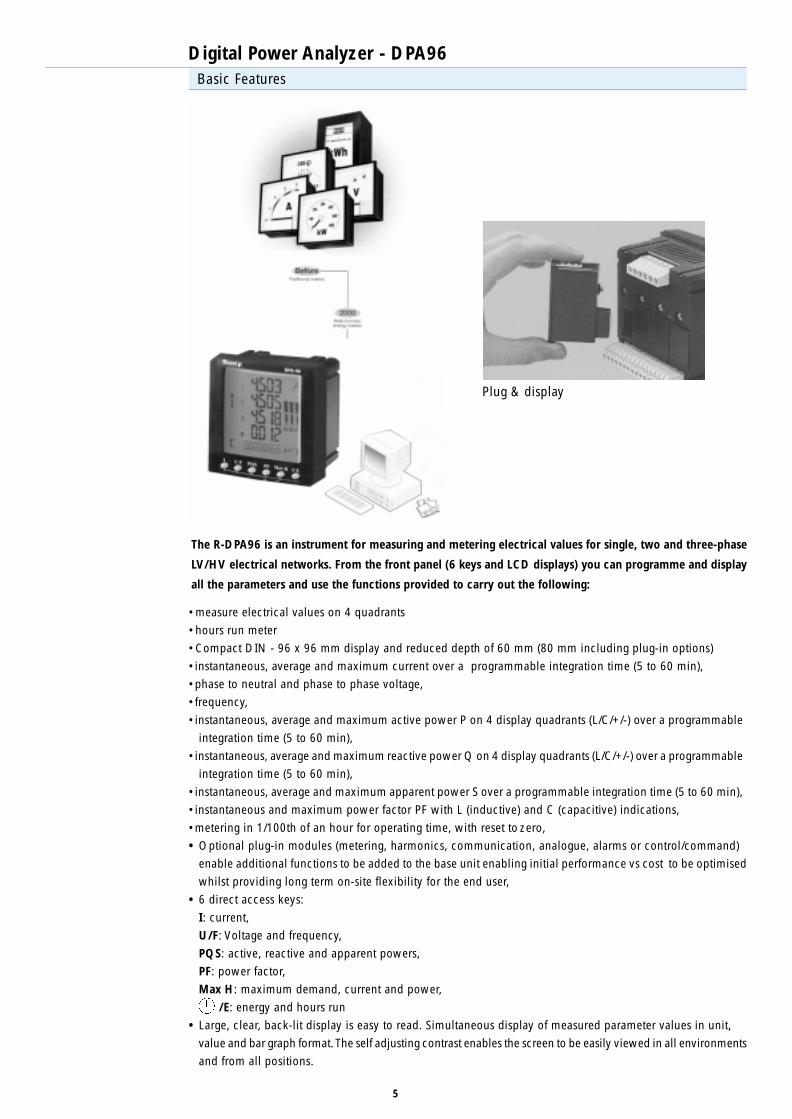
The R-DPA96 is an instrument for measuring and metering electrical values for single, two and three-phase
LV/HV electrical networks. From the front panel (6 keys and LCD displays) you can programme and display
all the parameters and use the functions provided to carry out the following:
• measure electrical values on 4 quadrants
• hours run meter
• Compact DIN - 96 x 96 mm display and reduced depth of 60 mm (80 mm including plug-in options)
• instantaneous, average and maximum current over a programmable integration time (5 to 60 min),
• phase to neutral and phase to phase voltage,
• frequency,
• instantaneous, average and maximum active power P on 4 display quadrants (L/C/+/-) over a programmable
integration time (5 to 60 min),
• instantaneous, average and maximum reactive power Q on 4 display quadrants (L/C/+/-) over a programmable
integration time (5 to 60 min),
• instantaneous, average and maximum apparent power S over a programmable integration time (5 to 60 min),
• instantaneous and maximum power factor PF with L (inductive) and C (capacitive) indications,
• metering in 1/100th of an hour for operating time, with reset to zero,
• Optional plug-in modules (metering, harmonics, communication, analogue, alarms or control/command)
enable additional functions to be added to the base unit enabling initial performance vs cost to be optimised
whilst providing long term on-site flexibility for the end user,
• 6 direct access keys:
I: current,
U/F: Voltage and frequency,
PQS: active, reactive and apparent powers,
PF: power factor,
Max H: maximum demand, current and power,
/E: energy and hours run
• Large, clear, back-lit display is easy to read. Simultaneous display of measured parameter values in unit,
value and bar graph format. The self adjusting contrast enables the screen to be easily viewed in all environments
and from all positions.
Plug & display
Digital Power Analyzer - DPA96
6
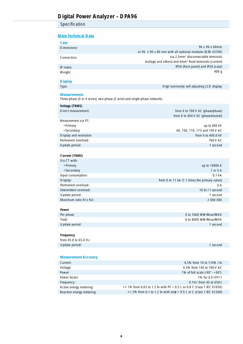
Specification
Main Technical Data
Voltage (TRMS)
Direct measurement:
Measurement via PT:
• Primary
• Secondary
Display and resolution
Permanent overload:
Update period:
CaseDimensions:
Connection:
IP index:
Weight:
96 x 96 x 60mm
or 96 x 96 x 80 mm with all optional modules (DIN 43700)
via 2.5mm2 disconnectable terminals
(voltage and others) and 6mm2 fixed terminals (current)
IP54 (front panel) and IP20 (case)
400 g
DisplayType: High luminosity self adjusting LCD display
MeasurementsThree-phase (3 or 4 wires), two-phase (2 wire) and single-phase networks
from 0 to 700 V AC (phase/phase)
from 0 to 404 V AC (phase/neutral)
up to 400 kV
60, 100, 110, 173 and 190 V AC
from 0 to 400.0 kV
760 V AC
1 second
Current (TRMS)
Via CT with:
• Primary
• Secondary
Input consumption:
Display:
Permanent overload:
Intermittent overload:
Update period:
Maximum ratio KI x KU:
up to 10000 A
1 or 5 A
0.1 VA
from 0 to 11 kA (1.1 times the primary value)
6 A
10 In / 1 second
1 second
2 000 000
Power
Per phase:
Total:
Update period:
0 to 1660 MW/Mvar/MVA
0 to 8000 MW/Mvar/MVA
1 second
Frequency
from 45.0 to 65.0 Hz
Update period: 1 second
Current:
Voltage:
Power:
Power factor:
Frequency:
Active energy metering:
Reactive energy metering:
Measurement Accuracy0.5% from 10 to 110% / In
0.5% from 140 to 700 V AC
1% of full scale (-90° - +90°)
1% for 0.5<FP<1
0.1Hz from 45 to 65Hz+/- 1% from 0.02 to 1.2 In with PF = 0.5 L or 0.8 C (class 1 IEC 61036)
+/- 2% from 0.1 to 1.2 In with sinϕ = 0.5 L or C (class 1 IEC 61268)

Digital Power Analyzer - DPA96
7
Specification (continue)
Auxiliary Supply110 to 440V AC
120 to 350V DC
Consumption:
Other version:
50/60 Hz +/- 10%
+/- 20%
10 VA
18 to 100 V DC (+/-10%)
Pulse outputsReed relays
No. of operations:
(100 V DC - 0.5 A - 10 VA)
<108
CommunicationRS 485:
Protocol:
Speed:
2 or 3 wires half duplex
JBUS/MODBUS protocol / RTU mode
2400 to 38400 Bauds
Galvanic insulation (AC insulation voltage)Auxiliary supply:
Voltage inputs:
Current inputs:
Serial link:
Pulse outputs:
4 kV
1.5 kV
1.5 kV
1.5 kV
1.5 kV
Operating conditionsOperating temperature:
Storage temperature:
Relative humidity:
-10° to +55°C (14° to 131°F)
-20° to +85°C (-4° to 158°F)
95%
StandardsMetering
CE-marking
Environment
IEC 61036 class 1
IEC 61268 class 2
IEC 61000-4/2-3-4-5-6-8-11
EN 50081-1
EN 50082-2
IEC 60068-2/6-11
Product code:R-DPA96 Basic model
R-Module-1 Plug in module for energy metering± kWh, ± kvarh and kVAh with two programmable pulse outputs
R-Module-2 Plug in module for energy metering + harmonicsI1, I2, I3, U12, U23, U31 and THD U/I up to harmonic no. 15
R-Module-3 Plug in module for communication RS 485 (JBUS/MODBUS protocol)2 or 3-wire RS485 with JBUS/MODBUS protocol, with transmission speed of up to38,400 bauds
R-Module-4 Plug in module for analogue outputs (0/4-20mA)Two configurable 0/4-20 mA analogue outputs
R-Module-5 Plug in module for alarms control/command (2 inputs/ 2 outputs)2 inputs for pulse metering or for input status. 2 outputs for alarm monitoring or outputcommand. The monitoring function allows upper and lower alarm thresholds to beprogrammed for the following parameters: 3I, 3U, In, ±∑P, F, PFL/C, THDI/U with timedelay and hysteresis options.
8
Basic Features
Power Quality Analyzer - PQA144
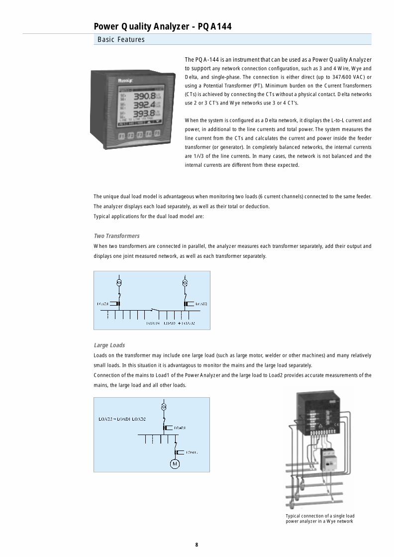
The PQA-144 is an instrument that can be used as a Power Quality Analyzerto support any network connection configuration, such as 3 and 4 Wire, Wye and
Delta, and single-phase. The connection is either direct (up to 347/600 VAC) or
using a Potential Transformer (PT). Minimum burden on the Current Transformers
(CTs) is achieved by connecting the CTs without a physical contact. Delta networks
use 2 or 3 CT’s and Wye networks use 3 or 4 CT’s.
When the system is configured as a Delta network, it displays the L-to-L current and
power, in additional to the line currents and total power. The system measures the
line current from the CTs and calculates the current and power inside the feeder
transformer (or generator). In completely balanced networks, the internal currents
are 1/√3 of the line currents. In many cases, the network is not balanced and the
internal currents are different from these expected.
The unique dual load model is advantageous when monitoring two loads (6 current channels) connected to the same feeder.
The analyzer displays each load separately, as well as their total or deduction.
Typical applications for the dual load model are:
Two Transformers
When two transformers are connected in parallel, the analyzer measures each transformer separately, add their output and
displays one joint measured network, as well as each transformer separately.
Large Loads
Loads on the transformer may include one large load (such as large motor, welder or other machines) and many relatively
small loads. In this situation it is advantagous to monitor the mains and the large load separately.
Connection of the mains to Load1 of the Power Analyzer and the large load to Load2 provides accurate measurements of the
mains, the large load and all other loads.
Typical connection of a single loadpower analyzer in a Wye network

9
Basic Features
Power Quality Analyzer - PQA144
Metered Values• True RMS measurements• Ultra rapid, real-time, cycle by cycle measurements, at 128 samples per cycle. Real-time values over 8 through 256
cycles for easy reading• Choice of models ranging from essential measurements only (Volts, currents, frequency and powers) to over 2000
electrical parameters• Min/Max values• Four quadrant readings (power, power factor)• Displays neutral voltage and current
Time-of-Use (TOU)• Time-of-Use information is automatically stored for each predefined period• PowerIQ software calculates electricity costs according to varying tariffs (based on time, season etc.)
Power Quality• Waveform display and capturing, at 128 samples per cycle• Harmonics analysis, up to 63rd harmonic (individual, THD, K and crest factors)• Sag/Swell recording (magnitude, duration and trigger events)
Compliance Monitoring• Compliance monitoring of international power quality standards• These monitoring operate on all product series
(e.g. the harmonics level is tested even if the meter doesn’t include harmonics display)
Logging & Recording• Up to 2048KB of flash memory• High speed data recording for short duration critical events• Logging of over 2000 parameters at scheduled intervals or by set-points• Min/Max recording of key parameters• Logging of setup changes, set-point and power quality events• Precise timestamp synchronized to external GPS (optional)
Input, Output & Relays• On board relay can be controlled automatically by internal set-points• Optional 4 digital inputs and 2 outputs for multiple purposes, such as synchronization to utility meter or to generate
energy pulsing (Wh, VArh and VAh)
Graphic Display & User Interface• Extra large graphic LCD screen• High visibility (FSTN technology)• Bright Backlight• Characters are displayed in varying sizes to enhance visibility from long distances• The user interface offers an easy to use, installation and configuration menu driven operation
Communication• Optional RS-485 or RS-232 communication port• Supported protocol: ElCom protocol - Rudolf’s unique ultra rapid communication protocol and ModBus RTU• Baud rate of up to 115200 BPS• Fully automated baud rate setup
Structure• Allows easy adaptation of the unit to current and future requirements• Easy upgrading of the firmwave (internal software)
Network Types• Supports any network connection configuration (3 and 4 Wire, Wye and Delta, single-phase etc.)• Feeder transformer (or local generator) current and power analysis (see Applications section)• Unique dual load model enables simultaneous analysis of two loads such as parallel-connected transformers, or mains
plus additional load (e.g., large motor, welder, capacitor bank)
Software• User-friendly PC software (PowerIQ)• Includes on-line help for easy use

10
Display Screens
Power Quality Analyzer - PQA144
Large Digit Screen
Permits simultaneoues display of 9 parameters: 3 measured values
plus 3 minimum and 3 maximum.
Parameters can be mixed, such as average voltage, current and
power factors. This unique feature allows analysis of the formost
parameters at a glance, without touching the unit. The PU% buttons
displays the values as a percentage from their nominal rating.
When using the dual load model, the readings are on all 3 loads .
Waveform Screen
This large graphic display allows easy monitoring of transients of
130/156µS (at 60/50Hz). The display includes detailed information
for each wave: the type and phase, THD, RMS, peak & bottom
values plus value at cursor position.
When using the dual load model, the readings are on all 3 loads .
Harmonics Screen
The graphic display enables inspection of the harmonics pollution
at a glance. The display includes detailed information for each
harmonic: type, phase, number of the harmonic, the value in
amperes/volts and in percent, the angle and the frequency.
When using the dual load model, the readings are on all 3 loads.
11
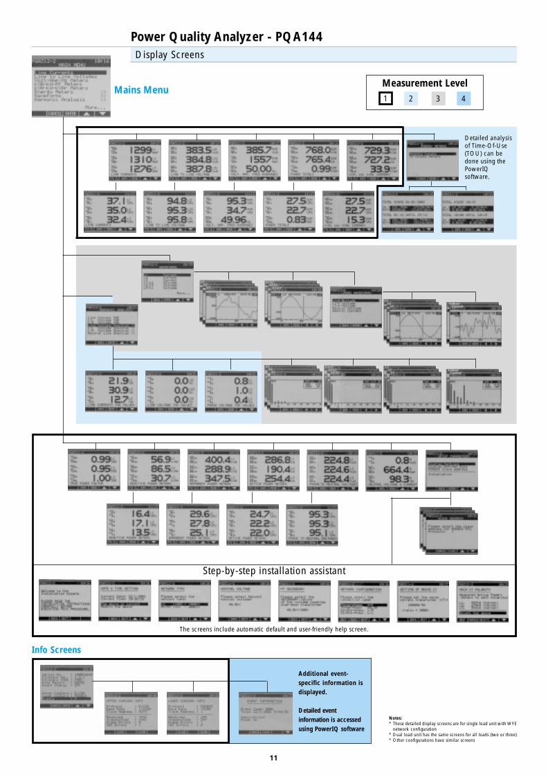
Detailed analysisof Time-Of-Use(TOU) can bedone using thePowerIQsoftware.
Display Screens
Power Quality Analyzer - PQA144
Mains Menu
Step-by-step installation assistant
Notes:* These detailed display screens are for single load unit with WYE
network configuration* Dual load unit has the same screens for all loads (two or three)* Other configurations have similar screens
Measurement Level1 2 3 4
The screens include automatic default and user-friendly help screen.
Info Screens
Additional event-specific information isdisplayed.
Detailed eventinformation is accessedusing PowerIQ software

12
Basic Features - PowerIQ Software
Power Quality Analyzer - PQA144
GeneralThis easy-to-use software displays the system’s status, as well as the measurement results on the numerous screens running
under Windows (95, 98, me, NT and 2000). PowerIQ integrates all Rudolf systems, allowing power quality analysis, cost
allocation, circuit optimization, demand & power factor monitoring. PowerIQ includes real-time measurements, as well as
comprehensive data logging and power quality analysis features. All screens allow customization, printing and exporting of
data. The network version enables complete intranet and internet operation, as well as modem access.
������������ �������
����������� ����������
����������� ����������
������� �������
������������ ����������� � !"��������� ������"�����
��#��
��#��
$��#�������������
$�%���&��"'(��)���� ������*�
$�%���&��"'(��)���� ������*�
$�%���&��"'(��)���� ������*
$�%���&��"'(��!+��#���*�
!"������"�'�����
13
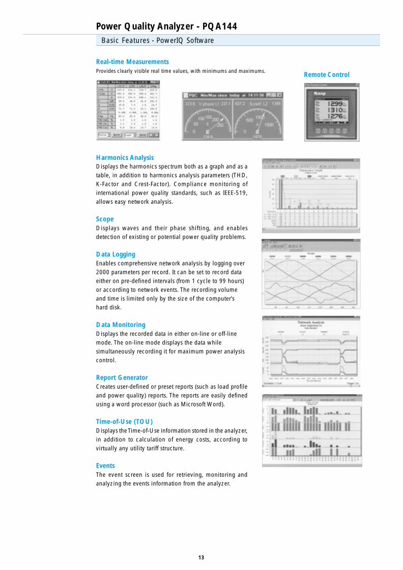
Power Quality Analyzer - PQA144Basic Features - PowerIQ Software
Real-time MeasurementsProvides clearly visible real time values, with minimums and maximums.
Remote Control
Harmonics AnalysisDisplays the harmonics spectrum both as a graph and as atable, in addition to harmonics analysis parameters (THD,K-Factor and Crest-Factor). Compliance monitoring ofinternational power quality standards, such as IEEE-519,allows easy network analysis.
ScopeDisplays waves and their phase shifting, and enablesdetection of existing or potential power quality problems.
Data LoggingEnables comprehensive network analysis by logging over2000 parameters per record. It can be set to record dataeither on pre-defined intervals (from 1 cycle to 99 hours)or according to network events. The recording volumeand time is limited only by the size of the computer’shard disk.
Data MonitoringDisplays the recorded data in either on-line or off-linemode. The on-line mode displays the data whilesimultaneously recording it for maximum power analysiscontrol.
Report GeneratorCreates user-defined or preset reports (such as load profileand power quality) reports. The reports are easily definedusing a word processor (such as Microsoft Word).
Time-of-Use (TOU)Displays the Time-of-Use information stored in the analyzer,in addition to calculation of energy costs, according tovirtually any utility tariff structure.
EventsThe event screen is used for retrieving, monitoring andanalyzing the events information from the analyzer.

14
Power Quality Analyzer - PQA144Technical Specification
LCD Display Size : 94 x 76 mm
LCD Display Resolution : Graphic 160 x 128 pixies
LCD Display Type : FSTN, LED backlight
Overall Dimensions : 144 x 144 x 120 mm [HxWxD]
Panel Cutout : 138x138 mm
Weight : 1.4 kg
Ambient Temperature : -20°C -+55°C
Storage Temperature : -25°C -+65°C
Direct Voltage Measurement : 347/600 V AC Max.
Current Measurement : ../5A (1A)
Relay Alarm : Max. 2A 250VAC
EMC Compatibilty : EN61000-4-2/3/4/5, ENV50204, ENV50141
Safety Standards : EN61010-1, EN50439-1, UL508
Protection Class : IP40
Analog Channels : 7 or 10
4 x Voltage Channels
3 x Current Channels
3 x Current Channels (optional Load2)
Communication (optional) : ElCom (Rudolf’s protocol), ModBus RTU
Power Supply :110 or 230V, 50/60 Hz
Power Consumption :15 VA
Harmonics Analysis : 1 through 63rd
Selection Guide
Full InstrumentationWiring DiagnosticsANSI C12.1 Accuracy
FrequencyCurrent, per phaseCurrent, NeutralCurrent, L-to-L (Transformer)Volts, L-to-LVolts, L-to-NVolts, Neutral
Real Power (kW)Reactive Power (kVAr)Apparent Power (kVA)Power Factor
Time-of-Use (TOU):- Real Energy (kWh)- Reactive Energy (kVArh)- Energy Accumulation Modes: in, out, net, total
THD (Current, Volts, L-to-L and L-to-N)K-Factor (Current, Volts, L-to-L and L-to-N)Harmonics (Current, Volts, L-to-L and L-to-N)
Waveforms (Current, Volts, L-to-L and L-to-N)Min/Max ReadingsDual Load Measurement
Event loggingData LoggingData/ Time StampingFlash Memory (Kilo Bytes)Maximum Flash Memory (Kilo Bytes)
RS-422/485 Communication Port - Elcom ProtocolRS-422/485 Communication Port - ModBus/RTUOnboard Alarm
•••
•••••••
••••
•
°
•256256
°°•
OptionsOptionsOptionsOptionsOptionsPrPrPrPrProduct Seriesoduct Seriesoduct Seriesoduct Seriesoduct Series
R-PQA144-110-2R-PQA144-110-2R-PQA144-110-2R-PQA144-110-2R-PQA144-110-2 R-PQA144-210-2R-PQA144-210-2R-PQA144-210-2R-PQA144-210-2R-PQA144-210-2 R-PQA144-311-2R-PQA144-311-2R-PQA144-311-2R-PQA144-311-2R-PQA144-311-2 R-PQA144-411-2R-PQA144-411-2R-PQA144-411-2R-PQA144-411-2R-PQA144-411-2
•••
•••••••
••••
•••
••
•
°
•5121024
°°•
•••
•••••••
••••
•••
•••
••
°
•5121024
°°•
•••
•••••••
••••
•••
•••
••
°
•••
10242048
°°•
L1, L2, L3 AvgNL12, L23, L31, AvgL12, L23, L31, AvgL1, L2, L3, AvgN
L1, L2, L3, SumL1, L2, L3, SumL1, L2, L3, SumL1, L2, L3, Sum
SumSum
L1, L2, L3, Avg, NL1, L2, L3, Avg, NL1, L2, L3, N
L1, L2, L3, N
0.10.20.20.20.20.20.2
0.30.30.30.3
0.50.5
0.20.20.2
0.2
Displayed PhasesDisplayed PhasesDisplayed PhasesDisplayed PhasesDisplayed Phases AccurAccurAccurAccurAccur. (%). (%). (%). (%). (%)(FS) ±1 dgt(FS) ±1 dgt(FS) ±1 dgt(FS) ±1 dgt(FS) ±1 dgt
• - included ° − optional
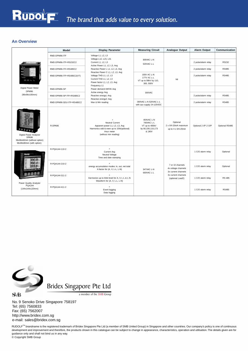
An Overview
RUDOLFTM brandname is the registered trademark of Bridex Singapore Pte Ltd (a member of SMB United Group) in Singapore and other countries. Our company’s policy is one of continuousdevelopment and improvement and therefore, the products shown in this catalogue can be subject to change in appearance, characteristics, operation and utilisation. The details given are forguidance only and shall not bind us in any way.© Copyright SMB Group
No. 9 Senoko Drive Singapore 758197Tel: (65) 7560833Fax: (65) 7562007http://www.bridex.com.sge-mail: [email protected]
����������� ������������������� ������������ ��
RMD-DPM96-ITF
RMD-DPM96-ITF+RS232C2
RMD-DPM96-ITF+RS485C2
RMD-DPM96-ITF+RS485C2(VT)
RMD-DPM96-SP
RMD-DPM96-SP-ITF+RS485C2
RMD-DPM96-SDU-ITF+RS485C2
Voltage L1, L2, L3
Voltage L12, L23, L31
Current L1, L2, L3
Active Power L1, L2, L3, Avg
Reactive Power L L1, L2, L3, Avg
Reactive Power C L1, L2, L3, Avg
Voltage THD L1, L2, L3
Current THD L1, L2, L3
Power factor L1, L2, L3, Avg
Frequency L1
Power demand kW/VA Avg
Active energy Avg
Reactive energyL Avg
Reactive energyC Avg
Max & Min reading
Display ParameterModel Measuring Circuit
300VAC
Analogue Output
Optional
2 x 0/4-20mA maixmum
up to 4 x 0/4-20mA
Alarm Output
2 pulse/alarm relay
2 pulse/alarm relay
2 pulse/alarm relay
2 pulse/alarm relay
2 pulse/alarm relay
Communication
RS232
RS485
RS485
RS485
RS485
Digital Power Meter
DPM96
(96x96x100mm)
Power Quality AnalyzerPQA144
(144x144x120mm)
Digital Power AnalyzerDPA96
96x96x60mm (without option)96x96x80mm (with option)
347VAC L-N
600VAC L-L
404VAC L-N700VAC L-L
VT up to 400kVby 60,100,110,173
& 190V
Optional 2 I/P 2 O/P Optional RS485R-DPA96
+Current Avg
Neutral VoltageTime and date stamping
+energy accumulation modes: in, out, net total
K-factor for (A, V, L-L, L-N)
+Harmonics up to 63rd level for A, V, L-L & L-N
Waveform for (A, V, L-L, L-N)
+Event loggingData logging
+Neutral Current
Apparent power L1, L2, L3, AvgHarmonics odd & even up to 15th(optional)
Hour meter(without min reading)
1 C/O alarm relay
1 C/O alarm relay
1 C/O alarm relay
1 C/O alarm relay
Optional
Optional
RS 485
RS485
R-PQA144-110-2
R-PQA144-210-2
R-PQA144-311-2
R-PQA144-411-2
300VAC L-N
520VAC L-L
100V AC L-N177V AC L-L
VT up to 99kV by 110,300, 500V
300VAC L-N 520VAC L-Lwith aux supply 24-120VDC
7 or 10 channels
4x voltage channels
3x current channels
3x current channels
(optional Load2)
Nil