digora fmx - dental discovery · 8200823 i digora® fmx service manual 1. contents digora ® fmx...
TRANSCRIPT

8200823 I
Digora® fmx Service Manual 1. CONTENTS
Digora® fmxService Manual
Medical Device Directive
93/42/EEC
04 / 2003
Digora® fmx - Service ManualDocument code 8200823
Original approved English language version
Manufactured by SOREDEXP.O. BOX 250
00031 HELSINKI, FINLANDTel. +358 010 394 820Fax +358 9 701 5261

1. CONTENTS Digora® fmx Service Manual
II 8200823
Windows™ is a trademark of Microsoft Corporation.
Digora® is a registered trademark of Soredex.
Soredex endeavours to produce product documentation that is accurate and up todate. However, our policy of continual product development may result in changes toproducts that are not reflected in the product documentation. Therefore, this docu-ment should not be regarded as an infallible guide to current product specifications.Soredex maintains the right to make changes and alterations without prior notice.
8200823 III
Digora® fmx Service Manual 1. CONTENTS
Contents
1. ABOUT THIS MANUAL ...................................................................................... 1-1Main Mechanical Assemblies ............................................................................. 1-2
2. WARNINGS AND SYMBOLS ............................................................................. 2-12.1 Dangerous voltages ..................................................................................... 2-12.2 Laser radiation ............................................................................................. 2-22.3 Safety/service switch operation .................................................................... 2-22.4 Precautions with the imaging plates.............................................................. 2-32.5 Weight of the scanner ................................................................................... 2-32.6 Fragile components...................................................................................... 2-42.7 Responsibility ............................................................................................... 2-42.8 Unauthorized modifications .......................................................................... 2-42.9 Symbols ....................................................................................................... 2-52.10 Warnings .................................................................................................... 2-62.11 Dimensions (with optional Autoloader) ....................................................... 2-6
3. COVERS AND TYPE LABEL ............................................................................. 3-13.1 Opening the covers ...................................................................................... 3-13.2 Closing the covers ........................................................................................ 3-53.3 Type Label ................................................................................................... 3-6
4. FUNCTIONAL DESCRIPTION ........................................................................... 4-14.1 Functional Description .................................................................................. 4-14.2 Imaging plate principle.................................................................................. 4-24.3 X-ray film and intensifying screen.................................................................. 4-24.4 The Imaging plate ......................................................................................... 4-24.5 The scanner ................................................................................................. 4-34.6 Noise ........................................................................................................... 4-34.7 Preread ........................................................................................................ 4-44.8 Main functions .............................................................................................. 4-4
5. TRANSPORT UNIT ............................................................................................ 5-15.1 Possible problems ....................................................................................... 5-2
5.1.1 Cleaning the screw shaft ....................................................................... 5-25.2 The flywheel .................................................................................................. 5-5
5.2.1 Adjusting the plastic tongue .................................................................. 5-55.2.2 Aligning the shaft .................................................................................. 5-6
5.3 Light collecting tube adjustment .................................................................... 5-6
6. LASER DIODE ASSEMBLY ............................................................................... 6-16.1 Laser alignment ............................................................................................ 6-16.2 Laser diode assembly replacement .............................................................. 6-2

1. CONTENTS Digora® fmx Service Manual
IV 8200823
7. GALVANOMETER .............................................................................................. 7-1
8. OPTICAL COMPONENTS .................................................................................. 8-18.1 Mirrors and lens assemblies ......................................................................... 8-28.2 Slotted optical switch .................................................................................... 8-28.3 Reflective sensor .......................................................................................... 8-28.4 Adjustment of reflective sensor ..................................................................... 8-3
9. PREREAD LENS MOTOR.................................................................................. 9-1
10. ELECTRICAL DESCRIPTION DXR-40 XXX-02 ............................................ 10-110.1 Functions connected to T4101 stepper drive and HV supply PCB............. 10-110.2 Functions connected to P4000-2 microprocessor PCB ............................ 10-110.3 Functions connected to T4501 key and display PCB ................................ 10-210.4 The PC boards ......................................................................................... 10-2
11. PROCESSOR BOARDS P4001 AND P4000-2 ............................................... 11-111.1 Functional description; Main Features: ....................................................... 11-111.3 CPU interface ............................................................................................ 11-211.3 Photo multiplier amplifier ........................................................................... 11-211.4 Adjustment of manual potentiometers ......................................................... 11-311.5 Galvanometer driver .................................................................................. 11-411.6 Plate detector ............................................................................................ 11-611.7 Test points ................................................................................................. 11-711.8 Led indicators ........................................................................................... 11-711.9 P4000-2 connector pinouts ........................................................................ 11-8
P4001 Processor board, circuit diagram. ................................................... 11-11P4001 Processor board, circuit diagram. ................................................... 11-12P4001 Processor board, circuit diagram. ................................................... 11-13P4001 Processor board, circuit diagram. ................................................... 11-14P4001 Processor board, component layout. ............................................... 11-15P4000-1 Processor board, circuit diagram. ................................................ 11-16P4000-1 Processor board,circuit diagram. ................................................. 11-17P4000-1 Processor board, circuit diagram. ................................................ 11-18P4000-1 Processor board, circuit diagram. ................................................ 11-19P4000-2 Processor board. ......................................................................... 11-20
12. STEPPER DRIVE AND HIGH VOLTAGE SUPPLY T4101............................. 12-112.1 Functional description .............................................................................. 12-1
Main features .............................................................................................. 12-112.2 High voltage power supply ........................................................................ 12-1
Specifications: ............................................................................................ 12-112.3 Control signals ......................................................................................... 12-212.4 Micro stepper interface............................................................................. 12-212.5 Test points ................................................................................................ 12-312.6 Laser and photomultiplier high voltage control ........................................... 12-4
Circuit Diagram for T4101 Stepper drive and high voltage supply ................ 12-5Circuit Diagram for Stepper drive and high voltage supply T4101 ................ 12-6Circuit Diagram for Stepper Drive and high voltage supply T4101 ............... 12-7Component layout for T4101 Stepper drive and high voltage supply ............. 12-8

8200823 V
Digora® fmx Service Manual 1. CONTENTS
13. PMT BIAS T4300 ............................................................................................ 13-113.1 Photomultiplier tube biasing ..................................................................... 13-113.2 PMT signal preamplifier ........................................................................... 13-113.3 T4300 Circuit Diagram for photomultiplier ................................................ 13-213.4 T4300 Component layout for photomultiplier ............................................. 13-3
14. MAINS POWER SUPPLY T4400 .................................................................... 14-1
15. KEY AND DISPLAY T4501 ............................................................................. 15-1Circuit Diagram for Key and Display T4501 ................................................ 15-3Component layout for Key and Display T4501 ............................................. 15-4
16. PC INTERFACE ADAPTERS ......................................................................... 16-116.1 P4602 ...................................................................................................... 16-116.2 P4601 ...................................................................................................... 16-1
16.2.1 Micro controller and dual port ram ..................................................... 16-116.2.2 Interface board connection for opto couplers ..................................... 16-116.2.3 Control Signals ................................................................................. 16-216.2.4 Test points ........................................................................................ 16-316.2.5 CONNECTOR PINOUTS J4601 (to PC bus) .................................... 16-416.2.6 CONNECTOR PINOUTS J4602 (to Digora rear panel) ..................... 16-4P4602-1 Circuit Diagram for Interface Adapter ............................................ 16-5P4602-1 Component layout for Interface Adapter ........................................ 16-6P4601 Circuit Diagram for Interface Adapter ............................................... 16-7P4601 Component layout for Interface Adapter............................................ 16-8
17. SCANNER SOFTWARE ................................................................................. 17-117.1 Timing of the main functions ...................................................................... 17-1
17.1.1 Power-on sequence consists of: ....................................................... 17-117.1.2 Image readout sequence consists of: ................................................ 17-117.1.3 Calibration sequence consists of: ..................................................... 17-2
17.2 Software versions ..................................................................................... 17-2Versions 3.00 and 3.10 ............................................................................... 17-2Versions 3.01 and 3.11 ............................................................................... 17-2Versions 4.01 and 4.11 ............................................................................... 17-2
18. DIGORA SERVICE ASSISTANT (DSA) .......................................................... 18-118.1 Installation ................................................................................................ 18-118.2 Commands, Parameters and Actions ....................................................... 18-2
18.2.1 General command ............................................................................ 18-218.2.2 Function commands ......................................................................... 18-3
18.3 Readout modes........................................................................................ 18-318.4 Function descriptions ............................................................................... 18-5

1. CONTENTS Digora® fmx Service Manual
VI 8200823
19. CALIBRATION AND ADJUSTMENT .............................................................. 19-119.1 Setting the high voltage ............................................................................ 19-119.2 Setting the x-ray dose ............................................................................... 19-119.3 Fine-tuning the mechanism ....................................................................... 19-219.4 Calibration parameters ............................................................................. 19-219.5 Usable calibration ranges ......................................................................... 19-319.6 How the calibration range is achieved ...................................................... 19-319.7 Control of the gray scale output of the scanner .......................................... 19-419.8 Control of the gray scale display of Digora for Windows............................ 19-5
20. TROUBLESHOOTING.................................................................................... 20-1
21. LIST OF ACCESSORIES/RECOMMENDED SPARE PARTS ....................... 21-121.1 Accessories: ............................................................................................ 21-121.2 Recommended spare parts for Digora fmx: .............................................. 21-3
22. LIST OF TOOLS REQUIRED ......................................................................... 22-122.1 Allen keys: ................................................................................................ 22-122.2 Closed loop wrenches: ............................................................................. 22-122.3 Screwdrivers: ........................................................................................... 22-122.4 Torque spanners for torques of ................................................................. 22-122.5 Miscellaneous .......................................................................................... 22-1
23. MAINTENANCE SCHEDULE ........................................................................ 23-1
24. AUTOLOADER ............................................................................................... 24-124.1 Autoloader ................................................................................................ 24-124.2 Installation of the Autoloader ..................................................................... 24-324.3 Adjustment of the Microswitch ................................................................... 24-7
25. SPECIFICATIONS AND SYSTEM REQUIREMENTS .................................... 25-1
26. CONVERTING A DIGORA TO A DIGORA FMX .............................................. 26-1Instructions ....................................................................................................... 26-2INTERFACE BOARD ....................................................................................... 26-8
Upgrading Interface board version P4600 to version P4601 ....................... 26-8Upgrading Interface board version P4601 .................................................. 26-9
SCANNER DRIVER 2.20 ............................................................................... 26-10DIGORA fmx units ..................................................................................... 26-10
CALIBRATING THE SCANNER ...................................................................... 26-11

1 - 18200823
Digora® fmx Service Manual 1. ABOUT THIS MANUAL
1. ABOUT THIS MANUALThis manual describes how to service and maintain the Digora fmx intraoralimaging plate scanner.
Please read the warnings and precautions before starting to service ormaintain the scanner.

82008231 - 2
1. ABOUT THIS MANUAL Digora® fmx Service Manual
Main Mechanical AssembliesThese assemblies are described in detail later in this manual.
FIGURE 1-1
1 Transport Unit2 Transport Motor3 Galvanometer4 Optical Component5 Preread Lens Motor6 Processor Board P40007 Stepper Drive and High Voltage Supply T41018 Photo Multiplier T43009 Main Power Supply T440010 Keys and Display Board T450111 Laser Diode Assembly

2 - 18200823
Digora® fmx Service Manual 2. WARNINGS AND SYMBOLS
2. WARNINGS AND SYMBOLSThe safety of all the parties involved has been a major consideration duringthe design and development of the Digora system. Proper care, use andobservance of all precautions will insure safe and reliable operation. Misuse,however, can result in damage to the equipment or serious danger to theservice personnel, operator or patient.
2.1 Dangerous voltages• in the mains switch assembly (line voltage) (1).• in the mains power supply board T4400 (line voltage and its rectified
peak value) (2).• in the high voltage power supply for the photomultiplier tube on the T4100
board. There is a led which is lit when the high voltage is on (up to 1000volts) (3).
• in the photomultiplier tube itself and its bias board T4300 (up to 900volts) (4).
• in the wires and connectors between these parts. The parts carrying thelethal voltages are protected from unintentional touching but the protec-tion does not totally prevent touching the high voltage power supply forthe photomultiplier tube on the T4100 board (4). The lightning symbols forlethal voltage appear in the tab preventing direct access to the highvoltage supply for the photomultiplier tube on the T4100 board.
FIGURE 2 - 1
2. WARNINGS AND SYMBOLS Digora® fmx Service Manual
82008232 - 2
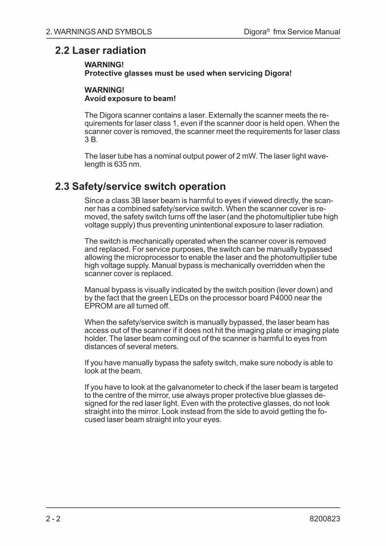
2.2 Laser radiationWARNING!Protective glasses must be used when servicing Digora!
WARNING!Avoid exposure to beam!
The Digora scanner contains a laser. Externally the scanner meets the re-quirements for laser class 1, even if the scanner door is held open. When thescanner cover is removed, the scanner meet the requirements for laser class3 B.
The laser tube has a nominal output power of 2 mW. The laser light wave-length is 635 nm.
2.3 Safety/service switch operationSince a class 3B laser beam is harmful to eyes if viewed directly, the scan-ner has a combined safety/service switch. When the scanner cover is re-moved, the safety switch turns off the laser (and the photomultiplier tube highvoltage supply) thus preventing unintentional exposure to laser radiation.
The switch is mechanically operated when the scanner cover is removedand replaced. For service purposes, the switch can be manually bypassedallowing the microprocessor to enable the laser and the photomultiplier tubehigh voltage supply. Manual bypass is mechanically overridden when thescanner cover is replaced.
Manual bypass is visually indicated by the switch position (lever down) andby the fact that the green LEDs on the processor board P4000 near theEPROM are all turned off.
When the safety/service switch is manually bypassed, the laser beam hasaccess out of the scanner if it does not hit the imaging plate or imaging plateholder. The laser beam coming out of the scanner is harmful to eyes fromdistances of several meters.
If you have manually bypass the safety switch, make sure nobody is able tolook at the beam.
If you have to look at the galvanometer to check if the laser beam is targetedto the centre of the mirror, use always proper protective blue glasses de-signed for the red laser light. Even with the protective glasses, do not lookstraight into the mirror. Look instead from the side to avoid getting the fo-cused laser beam straight into your eyes.

2 - 38200823
Digora® fmx Service Manual 2. WARNINGS AND SYMBOLS
2.4 Precautions with the imaging platesThis information is also found in the user manual.
For patient safetyThe imaging plate must be sealed into a tight protective bag, because• the plate requires protection against light and moisture• the patient must be protected against contamination from other patients• the active substance under the plastic coating of the plate is toxic.
Although an imaging plate is harder to swallow than intraoral dental film,never use imaging plates with patients that might swallow or chew the plate.
If the patient swallows the imaging plate, it must be immediately removed bya physician from the patients body. A swallowed plate will most likely betrapped in the esophagus.
If the patient bites or chews the plate so that the plate is damaged, the pa-tient's mouth must be rinsed with a large volume of water and the plate mustbe discarded. If the patient manages to bite off some of the white substanceand swallow it, a gastric lavage must be performed immediately.
Never place the imaging plate into the patient's mouth without enclosing itfirst into a tightly sealed protective bag. If you notice that the protective baghas leaked, discard the imaging plate.
Do not use cracked, chipped, bent, soaked or otherwise damaged imagingplates.
2.5 Weight of the scannerThe scanner weights 20 kilograms. Use caution when moving it to avoidhurting yourself.

2. WARNINGS AND SYMBOLS Digora® fmx Service Manual
82008232 - 4
2.6 Fragile componentsAlthough the whole scanner is a precision optical measuring device, there aresome components that are especially vulnerable:• galvanometer tail: hits• galvanometer mirror assembly: damage when moving the light guiding
tube• laser position, laser end mirrors: shocks, hits• Photomultiplier tube: sensitive to bright ambient light if out of its metal tube
or if high voltage is applied while the scanner cover has been removed• Photomultiplier tube: fixing screws of the steel tube must be short enough
to prevent damaging the PMT• transport mechanism, optics: dust and dirt• bending aluminium: screws fixing the galvanometer, the rotatable right
angle mirror, the lift mechanism, the lens holders and the steel tube con-taining the photomultiplier tube
2.7 ResponsibilityIt is the responsibility of the owner to ensure that the system is operated onlyby properly trained, qualified personnel who have obtained credentials fromlocal, state, and federal authorities where required.
If the system does not operate properly or fails to respond to the controls asdescribed in the User's Manual, the owner should call the nearest manufac-turer representative to troubleshoot and repair the system.
The owner must make certain that only properly trained, qualified servicepersonnel undertake the installation, maintenance, calibration, and repair ofthe system.
Address questions and comments regarding safety to the appropriateSoredex Service Organization.
2.8 Unauthorized modificationsUnauthorized changes or modifications to any part of the system could haveharazdous consequences. Changes or modifications must not be madeunless specifically authorized by Soredex.

2 - 58200823
Digora® fmx Service Manual 2. WARNINGS AND SYMBOLS
Action Button
Action Indicator
Power ON indicator"ON" only for a part ofequipment
Image Size Selector
Normal Size Indicator
Small Size Indicator
LASER RADIATION
Attention, consultaccompanyingdocuments
UL ClassificationSymbol
2.9 Symbols
ON (Power: Connectionto the mains)
OFF (Power: Disconnectionfrom the mains)
Alternating current
Protective earth (Ground)
Earth (Ground: functional)
DANGEROUS VOLTAGE
This is a classification symbol,for a type B applied part equipment,IEC-601-1
Interface Cable Connector
CE (0537) SymbolMDD 93/42/EEC

2. WARNINGS AND SYMBOLS Digora® fmx Service Manual
82008232 - 6
2.10 WARNINGS
CLASS 1 LASER EQUIPMENT
DANGER: Any failure to follow the recommendations and instruc-tions given in this manual may expose the user to laser radiationexceeding the class 1 specifications.
- This scanner must only be used to read image plates, supplied by themanufacturer and must not be used for any other purpose.
- This unit or its accessories must not be modified, altered orremanufactured in any way.
- Annual maintenance and repair can be performed by the manufacturedauthorized service personnel only.
- Only imaging plates and protective bags supplied by the manufacturershall be used with the system.
- This device can interfere other devices due to its EMC.- This device can be interfered by other devices due to the EMC.
2.11 DIMENSIONS (with optional Autoloader)

3 - 18200823
Digora® fmx Service Manual 3. COVERS AND TYPE LABEL
3. COVERS AND TYPE LABEL3.1 Opening the covers
When removing the covers of the Digora scanner, first remove the cover inthe middle that is held in place with magnets.
If the unit has a Autoloader, it must be removed prior to removing the topcover. To do that follow the instructions below.
1. Remove the Autoloader rear cover by removing M4 screw (1) at the rear.
FIGURE 3 - 1: Removing rear covers
2. Remove the Autoloader front cover by removing the three M3 screws (1)(Figure 3-2) and one M4 screw (1) (Figure 3-3)
FIGURE 3 - 2: Removing front cover

82008233 - 2
3. COVERS AND TYPE LABEL Digora® fmx Service Manual
1 Open the four M4 Allen screws (2) (Figure 3-3 and 3-4) of the scannerfront panel.
2 Grip the front panel from the left hand side of it and push it to the left torelease the two hidden supports holding the front panel in place. Repeatthis to the other side of front panel.
3 Open the two M3 allen screws in the left hand side of the revealed scan-ner front panel and one in the right top corner.
4 Disconnect the Autoloader motor and microswitch from the T4501 pcb.Remove the autoloader by removing the two M4 screws (5) (Figure 3-3).
FIGURE 3 - 3: Opening front panels
FIGURE 3 - 4: Opening front panels

3 - 38200823
Digora® fmx Service Manual 3. COVERS AND TYPE LABEL
FIGURE 3 - 5: Opening front panels
FIGURE 3 - 6: Opening scanner cover

82008233 - 4
3. COVERS AND TYPE LABEL Digora® fmx Service Manual
5. Then open the two (2) M4 allen screws at rear, holding the top cover inplace.
FIGURE 3 - 7: Removing scanner cover
6 Now you can lift off the scanner cover by first pushing it slightly inwardsfrom the sides.
7 Since the cover is fitting tightly in the longitual grooves at the sides of thescanner base plate, it may be somewhat tight. Don't let the cover tiltwhen lifting it up avoid it getting stuck in vertical direction. When you liftthe cover off, a flap inside the cover toggles the safety/service switch thatdisables the laser tube and the power supply of the photomultiplier tube.

3 - 58200823
Digora® fmx Service Manual 3. COVERS AND TYPE LABEL
3.2 Closing the covers
When you close the covers, make sure they don't disengage the cables fromtheir connectors or make any of the cables to get trapped.
FIGURE 3 - 8: Assembling top cover

82008233 - 6
3. COVERS AND TYPE LABEL Digora® fmx Service Manual
3.3 Type Label
FIGURE 3 - 9: Type Label
Digora scanner´s type label is fitted into the back panel. Digora´s typenumber is DXR40.
1. and 2. These digits are for identification of the country or language:
0 General (English)1 UK only2 German3 USA4 Australia5 France6 Finland and Sweden7 Russian8 Italy9 Spain10 Portugal11 Japan2x-9x OEM products
3. This digit is for identification different hardware components inside thescanner:
0 Aerotech laser tube1 Melles Griot laser tube2 Laser diode
4. and 5. These digits are for hardware version identification numbers:
0 Pilot production version1 1st production version2 2nd production version3 3rd production version (Digora fmx)

4 - 18200823
Digora® fmx Service Manual 4. FUNCTIONAL DESCRIPTION
4. FUNCTIONAL DESCRIPTION4.1 Functional Description
Digora imaging system replaces dental intraoral x-ray films with imagingplates. Film development and chemicals are replaced by reading the platesin the Digora scanner. Film archive is replaced by storing the images in thecomputer. There is no x-ray source included in Digora imaging system.
FIGURE 4 - 1: Fmx unit with the interface board, imaging plates, imagingplate box and software diskettes/CD´s.
FIGURE 4 - 2: Fmx unit with the Autoloader, interface board, imagingplates, imaging plate box and software diskettes/CD´s.

82008234 - 2
4. FUNCTIONAL DESCRIPTION Digora® fmx Service Manual
Digora imaging system consists of imaging plates, protective bags forimaging plates, the Digora scanner, an interface board and a Windowsbased software, Digora for windows. Optional Autoloader is also availablefor scanning imaging plates in series.
4.2 Imaging plate principleDigital imaging plates produce X-ray images of high quality and low noise,and they require only 20 to 50 percent of the dose required for highspeedfilm imaging. It is, however, possible to use the same dose as used for x-rayfilm without any risk of overexposure. If you want, you can reduce the X-raydose even lower, to just 10 percent of the dose required when film is used. Atthis very low exposure level there is an increased level of noise in the im-ages, but this may be an acceptable trade-off for decreasing exposurelevels.
4.3 X-ray film and intensifying screenBefore explaining the details of the digital imaging plate, here is a shortreview of the operating principles of the two imaging methods.
Radiographic dental imaging film is sensitive to light but relatively insensitiveto X-rays. When the film is used outside the patient's mouth, an intensifyingscreen is used to enhance the X-ray sensitivity of the film. The fluorescentsubstance of the intensifying screen is excited by the X-ray falling onto theplate. These excited states of the atoms revert to normal almost immedi-ately and, in so doing, generate visible light that exposes the x-ray film.
4.4 The Imaging plateThe fluorescent substance of an imaging plate has been modified to inhibitthe immediate revision of the excited states. This inhibition is usually suc-cessful up to a 50-percent level, which means that the imaging plate alsoacts as an intensifying screen. The remaining excited states, on the otherhand, are almost permanent. An exposed imaging plate stored in a darkenvironment and enclosed in a protective bag has more than half of theexcited states left after one day. An imaging plate exposed to ambient lightloses the excited states in less than a minute. An exposure of a few secondsto normal, indirect light will usually not affect the quality of the latent image onthe imaging plate.

4 - 38200823
Digora® fmx Service Manual 4. FUNCTIONAL DESCRIPTION
4.5 The scannerThe remaining excited states can be reverted by applying a red laser beamto the surface of the imaging plate. The laser beam is focused into a spotwhose diameter is 64 micrometres (0,07 mm) and directed on the surface ofthe plate. The laser beam reverts the excited states almost completely. Asthis happens, the imaging plate emits blue light of very low intensity ( by afactor of about 10-8 compared to the laser beam intensity). The scannerdetects and amplifies the image produced by the blue light. After thereadout, any remaining excited states are erased with a bright halogen light.
The amount of energy stored in the imaging plate is linearly proportional tothe x-ray exposure. The linearity is maintained throughout the entire doserange, which means that the imaging plate cannot be over- or underex-posed. In this sense, the imaging plate differs from both films and semicon-ductor sensors which are much more vulnerable to changes in the exposuredose.
To take full advantage of this valuable benefit of the imaging plate, the scan-ner prereads the imaging plate. Preread involves measuring the X-ray doseused for exposure before the actual readout. The preread is done with alower laser beam intensity so as not to revert too high a proportion of theexcited states before the actual readout. Because of the preread, the result-ing image is almost identical irrespective of the dose used for exposure.
4.6 NoiseThe dose has an effect on the quality of the image: the lower the x-ray expo-sure dose, the noisier (more granular) the resulting latent image. The noisein the latent image will be reproduced in the digital computer image andcannot be eliminated without compromising the resolution.
This phenomenon cannot be seen in traditional X-ray film which is ratherinsensitive to X-rays. Consequently, a relatively high dose must be used inexposure. Such a high dose generates an image with a low noise level. Animage plate can always be exposed using a high dose; in such a case, theresulting noise level is as low as with film.
Other digital intraoral imaging approaches are based on semiconductorsensors. There are two types of such sensors: ones that use an intensifyingscreen, and ones that so not use it. When an intensifying screen is used, thenoise level is comparable to that of an imaging plate using the same dose.However, sensors without an intensifying screen produce very noisy imageswhen compared to those produced by imaging plates with the same dose.The fact that semiconductor sensors require a relative accurate exposure toproduce acceptable image makes it difficult to evaluate the effect of the x-ray dose on the noise level.

82008234 - 4
4. FUNCTIONAL DESCRIPTION Digora® fmx Service Manual
4.7 PrereadThe scanner prereads the imaging plate before the actual redout. Preread isbased on detecting the darkest area of the image. The success of prereaddepends on the contents of the image and, in particular, the level of diagnos-tic interest of the various dark or bright areas of the image. The scannerdeliberately reads the image with low contrast and thus includes shades ofless diagnostic interest. After the readout, the automatic grayscale adjust-ment function tries to "guess" how the dentist wants to see the image.
If the image read is so dark or bright that it cannot be fixed with grayscalecontrols, a new image has to be exposed. In such a case, the settings of theX-ray source should not be modified. After all, this would not help, because itis the image contents (pattern) that matters, not the exposure dose. Instead,you should enter a correction factor using the Readout Setup command ofthe Options menu to account for required correction in grayscales.
If the result of the readout is fine, but the automatic grayscale adjustmentproduces too dark or bright images, you should change the settings of theautomatic grayscale adjustment, using the Automatic Grayscale Adjustmentcommand in the Options menu.
4.8 Main functionsThe scanner reads the imaging plates using a scanning laser beam and alinear transport motion.
When the scanner start to read an imaging plate, it first prereads the platemeasuring the x-ray dose used in the exposure. It sets the internal amplifiedaccording to the measured signal level and starts the actual readout of theplate. In the readout, scanner's A/D converter reads pixel density values fromthe plate and sends them instantly to the PC interface board. Data from theboard is stored into PC memory and displayed the line on PC monitor.
After the readout the scanner erases the imaging plate using a bright halo-gen lamp. The scanner returns the erased imaging plate to the scanneropening. During the erasure, Digora for Windows automatically saves theimage on the PC hard disk. Digora for Windows then processes the imageaccording to user selectable options and displays the processed imageboth in an image window and in the patient card.

Digora® fmx Service Manual 5. TRANSPORT UNITl
5 - 18200823
5. TRANSPORT UNITThe transport unit features a screw shaft and a plastic tongue (2) that con-verts the rotation of the shaft to the linear motion of the imaging plate holder(1). The holder has an adjustment screw (4) that works together as a springwith the magnet (3) of the plastic tongue. Screw (5) prevents the tongue fromcoming too much out of the imaging plate holder.
FIGURE 5 - 1: Transport Unit

5. TRANSPORT UNIT Digora® fmx Service Manual
82008235 - 2
5.1 Possible problems
5.1.1 Cleaning the screw shaft
The screw, upper and lower quiding rods and the plastic tongue may gatherdust that enters into the scanner. Excessive amounts of dust may impair theimage quality. If necessary, clean the screw by wiping (use lint free cotton) itduring rotation. Clean also the rods and plastic tongue. To get access to thetongue, open the screw (5) and turn the tongue horizontally.
If wiping doesn't clean the screw, dismantle the transport mechanism, washthe screw thoroughly, oil it with thin oil and reassemble the transport mecha-nism. Use thin oil also on upper and lower guiding rods. Dismantle the trans-port mechanism the following way:
FIGURE 5 - 2
1 Remove the scanner front panels and the scanner cover.
FIGURE 5 - 3

Digora® fmx Service Manual 5. TRANSPORT UNITl
5 - 38200823
2 Move the imaging plate holder to the inner end of the screw shaft (closeto the stepper motor). You can move the imaging plate holder quickly ifyou pull the plastic tongue out with your nail.
FIGURE 5 - 4
3 Remove the M5 set screw fixing the outer end of the upper guiding rodand open the M4 set screw fixing the inner end of the upper guiding rod.
FIGURE 5 - 5
4 Push the upper guiding rod towards the stepper motor to clear the holefrom which you removed the M5 set screw.
FIGURE 5 - 6
5. TRANSPORT UNIT Digora® fmx Service Manual
82008235 - 4
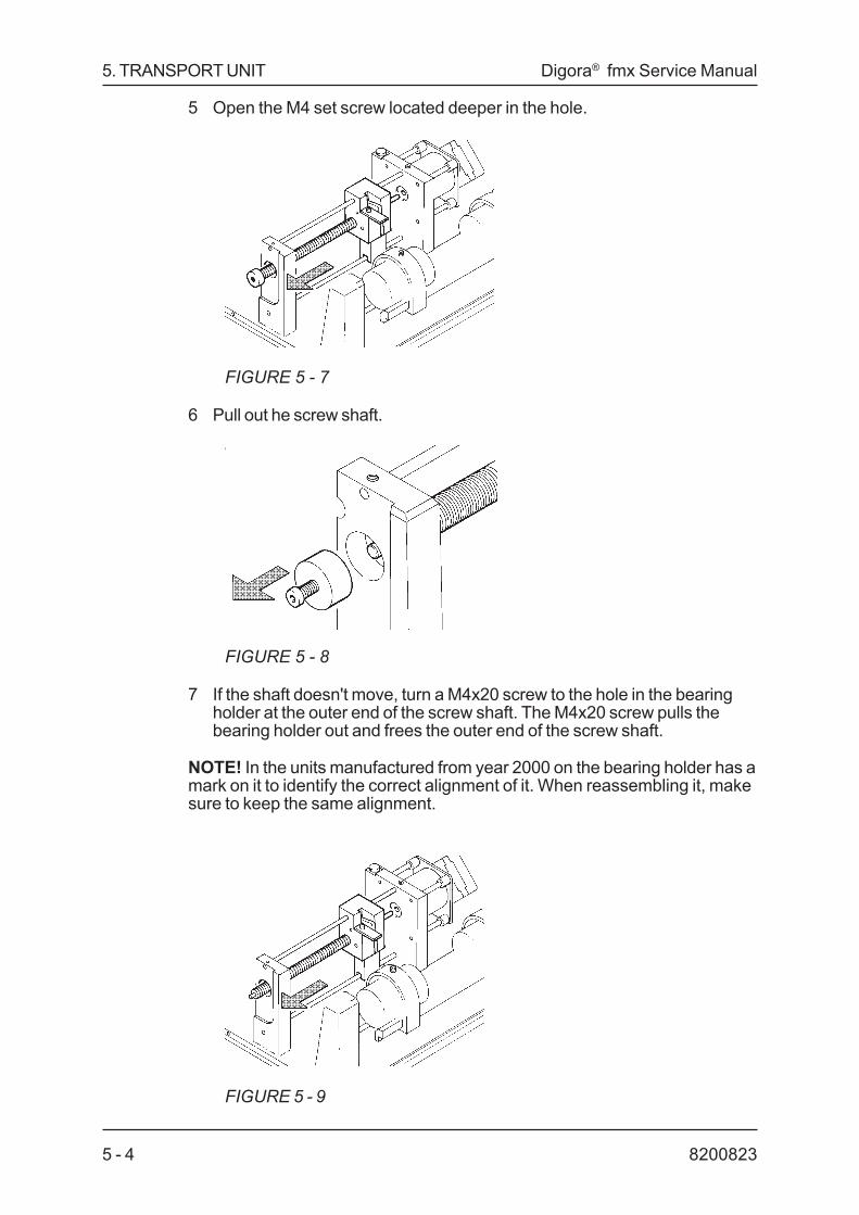
5 Open the M4 set screw located deeper in the hole.
FIGURE 5 - 7
6 Pull out he screw shaft.
FIGURE 5 - 8
7 If the shaft doesn't move, turn a M4x20 screw to the hole in the bearingholder at the outer end of the screw shaft. The M4x20 screw pulls thebearing holder out and frees the outer end of the screw shaft.
NOTE! In the units manufactured from year 2000 on the bearing holder has amark on it to identify the correct alignment of it. When reassembling it, makesure to keep the same alignment.
FIGURE 5 - 9

Digora® fmx Service Manual 5. TRANSPORT UNITl
5 - 58200823
8 Pull out the screw shaft but don't damage the thread by hitting it to thescanner frame. If you feel a strong rubbery resistance and can't pull theshaft out, remove the stepper motor and the flywheel to free the inner endof the shaft.
5.2 The flywheelTo remove the flywheel, open the four M5 nuts fixing the stepper motor as-sembly to the elastic absorbers. Put a screwdriver between the flywheel andthe aluminium plate of the stepper motor and force the stepper motor shaftout of the flywheel. Make sure you have the laser tube cover secured on itsplace to avoid hitting the laser tube with the stepper motor. Pull out the fly-wheel from the inner end of the screw shaft.
The flywheel is not secured to the shafts of the stepper motor and the trans-port mechanism. The rotating motion is coupled through O-rings located inthe internal grooves of the flywheel. If the O-rings are oily or hardened, theymay not function properly. Replace the whole flywheel with a spare part withready-assembled O-rings of right size and properties.
When you reassemble the transport mechanism, put a screwdriver betweenthe flywheel and the aluminium plate of the stepper motor to prevent theflywheel from sliding too close to the stepper motor and its fixing screws.
If you find it hard to push the shafts into the flywheel, moisten the O-rings withspirits to lubricate them temporarily. Do NOT use oil or water since oil de-creases friction permanently and water rusts the ends of the shafts whichmakes further removal of the flywheel very difficult.
Do not overtighten the M5 nuts fixing the stepper motor assembly to theelastic absorbers since this makes the M5 bolts to rotate inside the rubberthe next time anyone tries to open the nuts. If you find the bolt is rotatinginside the rubber, use plyers to keep the bolt steady while opening the nut.
5.2.1 Adjusting the plastic tongueThe screw shaft is not perfect and this causes two kinds of problems:
1 The Screw is not perfectly straight. This results in wide darker and lightervertical zones in uniform grey areas of the x-ray image. There are thirteenpairs of such areas during the whole length of the imaging plate.
2 The surface of the screw may initially have scratches, or dust and dirtmay accumulate on the screw. This results in more or less local, verynarrowvertical stripes of the x-ray image.
The plastic tongue of the imaging plate holder is adjustable to minimize theabove-mentioned problems. The basic adjustment is to turn the screw (4)until it pushes the plastic tongue noticeably and then take back somethingbetween half a turn and a full turn. The idea is to get the screw close to themagnet (3) of the tongue but to keep it so far away that it never touches themagnet when the screw shaft rotates.

5. TRANSPORT UNIT Digora® fmx Service Manual
82008235 - 6
After the basic adjustment, test the scanner by reading a few all-grey x-rayimages to check for striping. If disturbing striping is visible, the basic adjust-ment should be fine-turned to either direction to minimize the striping.
NOTE that this disturbing striping can be caused also because of otherreasons too (dust in upper or lower rods, etc.)
5.2.2 Aligning the shaftIn units manufactured from year 2000 on, the alignment of the shaft can beadjusted by turning the bearing holder (see fig 5-8). An adjustable construc-tion is recognized from the bearing holder which will have two holes to allowturning it.
Correct orientation of the bearing holder is found in the following way:
- Adjust the plastic tonque (imaging plate holder in the rearmost position)so that the imaging plate holder can just be moved without the plastictonque hitting the shaft
- Move the imaging plate holder from the front end to the rear end- The plastic tonque should not touch the shaft- Repeat this when the plastic tongue is adjusted in the outmost position- Adjust the orientation of the of the bearing holder by turning it so that the
criteria above will apply.
After alignment of the bearing holder the plastic tonque must be adjustedaccording to 5.2.1.
5.3 Light collecting tube adjustmentAlthough light collecting tube is not part of the transport unit it has someinfluence on the performance of the transport mechanics. The light collectingtube is the tube between the Photo Multiplier Tube and the Imaging Plateholder (refer figure 1-1 in this manual).
Adjustment of the light collecting tube means the adjusting the gap betweenthe Light Collecting Tube and the Imaging Plate Holder. The gap is factoryadjusted and should not need any adjustment. Incorrect adjustment mayallow Imaging Plates to drop inside the unit if they are inserted into thescanner incorrectly or carelessly.
The correct gap between the light collecting tube and the imaging plateholder is 0.6mm (+/- 0.2mm). If the tube needs to be adjusted:-move the imaging plate holder manually in front of the light collecting tube-loosen the nut that holds the steel belt around the light collecting tube-move the light collecting tube towards imaging plate holder so that theadjustment criteria is met. Make sure not to turn the tube so that it wouldtouch the galvanometer and prevent its movement- tighten the nut to tighten the light collecting tube in plate-loosen the two screws that are provided to tighten the PMT in place. Movethe PMT towards the light collecting tube until they are attached. Tighten thescrews.

Digora® fmx Service Manual 6. LASER TUBE AND POWER SUPPLY
6 - 18200823
6. Laser DIODE ASSEMBLY6.1 Laser alignment
Either when aligning the laser beam or/and when replacing the laser followthe precautions described in the chapter 2: Warnings and Symbols in thismanual. Always use the protective blue glasses.
The laser diode inside the laser diode assembly is fixed and it´s positioncan not be adjusted.
FIGURE 6 - 1: Laser Diode Assembly

6. LASER TUBE AND POWER SUPPLY Digora® fmx Service Manual
82008236 - 2
6.2 Laser diode assembly replacementLaser may need replacement if it isn´t turned on although everything else isworking properly (i.e. +12V voltage supply and signal Laseren are existing)
Before removing the laser diode assembly, be sure to turn off the scannerand mark the longitual position of the assembly.
FIGURE 6 - 2: Marking the longitual position of the assembly
Assemble the new laser diode assy in the same longitual position as the oldone.
Switch on the scanner and disactivate the safety switch. Switch on the laser(use DSA command LASER ON). Monitor the shape of laser beam on thegalvanometer mirror. Rotate the laser diode assy to get the laser spotinto the middle of galvanometer mirror at 45 degrees. See the figure 6-3.Tighten the laser diode assembly screw after assebly (torque 40 Nm).
Adjust by turning the round mirror assembly if necessary.
FIGURE 6 - 3: Laser spot on galvanometer mirror.
The factory alignment of the laser diode is done with a filtered video camerathat shows the actual shape of the laser spot at surface of the imaging plate.

Digora® fmx Service Manual 7. GALVANOMETER
7 - 18200823
7. GALVANOMETERThe galvanometer turns a little mirror that scans the laser spot in verticaldirection over the imaging plate.
The horizontal position of the galvanometer is correct when the laser spothits the center of the galvanometer mirror.
FIGURE 7 - 1: Galvanometer

7. GALVANOMETER Digora® fmx Service Manual
82008237 - 2
The angular position of the galvanometer sets the vertical position of theimage on the screen. The angular position is correct when the laser spotreflected from the galvanometer mirror hits the center of the screw shaftwhile the galvanometer cable is disconnected from the driving electronics.The fine-tuning of the vertical position of the image on the screen is donewith the Calibration procedure activated from the Options menu.
The remove the galvanometer, loosen first the M5 screws fixing the steeltube of the photomultiplier tube and slide the steel tube to the left. Open thenthe M5 nut fixing the clamp for the light guiding tube. While opening the nut,hold the light guiding tube steady to avoid it from hitting the galvanometermirror. Keep the clamp off the way and remove carefully the light guidingtube. The screw fixing the galvanometer may be tight because it is clampingthe cast aluminium structure of the scanner frame. Use caution not to hit orbend the galvanometer tail.
The galvanometer mirror is glued into its holder. The mirror holder assemblyis available as a spare part.
Remove the mirror holder assembly by pulling it straight out. Be careful not tobend the shaft of the galvanometer. Push the new mirror holder assemblystraight onto the galvanometer shaft keeping both parts in your hands. DoNOT push them against the tabletop as this easily results in bending thegalvanometer shaft. When pushing the parts together, increase the pushingforce gradually until the holder slides onto the shaft. When sliding stops, theholder sits firmly on the shaft. Do NOT try to push it any further . Failure tofollow this mirror holder assembly replacement procedure may cause thegalvanometer to work very unlinearily.
Do NOT ever try to rotate the mirror holder in respect to the galva-nometer body. Always adjust the angular position of the galvanom-eter by rotating the whole galvanometer body in respect to the scan-ner frame.

Digora® fmx Service Manual 8. OPTICAL COMPONENTS
8 - 18200823
8. OPTICAL COMPONENTS
The laser beam is guided inside the scanner and focused by a right anglemirror, a lens assemby and the galvanometer. Other optical components inthe system are the slotted optical switch and the reflective sensor.
FIGURE 8 - 1: Optical Components; Lens Assembly and Mirror

8. OPTICAL COMPONENTS Digora® fmx Service Manual
82008238 - 2
8.1 Mirrors and lens assembliesThe right angle mirror is designed to reflect the red laser light. Reflectiontakes place on the outer surface. The outer surface is kept in contact with theprecision machined aluminium surface of the scanner frame with a leafspring. The outer surface of the mirror and lenses must be reasonably free ofdust and absolutely free of fingerprints.
Use oilless compressed air to blow off the dust from the mirror and lenses. Ifyou use compressed air from a spray can, keep the can in vertical positionwhen spraying the air.
To remove particles that can't be blown off from the mirror on lenses, wipethem with a tissue moistened with clean spirits that doesn't leave any re-sidual film on the surfaces. If you wipe them as dry, use a soft cloth.
8.2 Slotted optical switchThe position of the slotted optical switch sets the horizontal position of theimage on the screen. If you need to open the screws of the slotted opticalswitch or the metal piece travelling through the slot, remember to recalibratethe scanner using the Calibration mode selectable from the Options menu.
8.3 Reflective sensorThe reflective sensor detects the white side of the imaging plate. The propersensor position is slightly tilted towards the inside of the scanner pointing tothe casted body of the unit. The guide plate of the imaging plate holder ispainted mat black to make it non-reflective. The sensor uses infrared lightwhich means it may interprete a black surface as white if the surface reflectsthe infrared light well enough.
Information from the reflective sensor is needed when the scanner is pushingthe imaging plate out (1) and when the user has pressed the Action button ofkeybord (2).
1 If the detector interpretes there is no imaging plate in the scanner, thescanner doesn't push the imaging plate holder fully out. If the imagingplate inside the scanner is of small size, the scanner pushes the imagingplate holder so much out that the reflective sensor can see the imagingplate.
2 When the user has pressed the Action button the scanner sends animage redout request to the computer if the reflective sensor has de-tected an imaging plate in the scanner.

Digora® fmx Service Manual 8. OPTICAL COMPONENTS
8 - 38200823
8.4 Adjustment of reflective sensorThe software measures a reference value of the reflective sensor signal aftereach power-on and interprets this to represent the absence of the imagingplate. When the reflective sensor then sees something that reflects signifi-cantly better, it interprets that to be the white side of the imaging plate. If thathappens to be the dark side of the imaging plate, the scanner tries to read it.It recovers the misinterpretation after having seen the real white side of theimaging at least once after power-on.
Reflective sensor functionality can be tested with DSA comman "Test reflec-tive sensor", see Chapter "DSA, Digora Service Assistant". It is recom-mended to use it to verify the functionality of reflective sensor.

8. OPTICAL COMPONENTS Digora® fmx Service Manual
82008238 - 4
Digora® fmx Service Manual 9. PREREAD LENS MOTOR
9 - 18200823
9. PREREAD LENS MOTOR
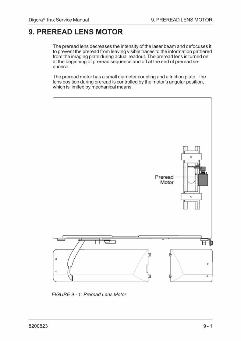
The preread lens decreases the intensity of the laser beam and defocuses itto prevent the preread from leaving visible traces to the information gatheredfrom the imaging plate during actual readout. The preread lens is turned onat the beginning of preread sequence and off at the end of preread se-quence.
The preread motor has a small diameter coupling and a friction plate. Thelens position during preread is controlled by the motor's angular position,which is limited by mechanical means.
FIGURE 9 - 1: Preread Lens Motor

9. PREREAD LENS MOTOR Digora® fmx Service Manual
82008239 - 2

Digora® fmx Service Manual 10. ELECTRICAL DESCRIPTION - DXR-40 XXX-03
10 - 18200823
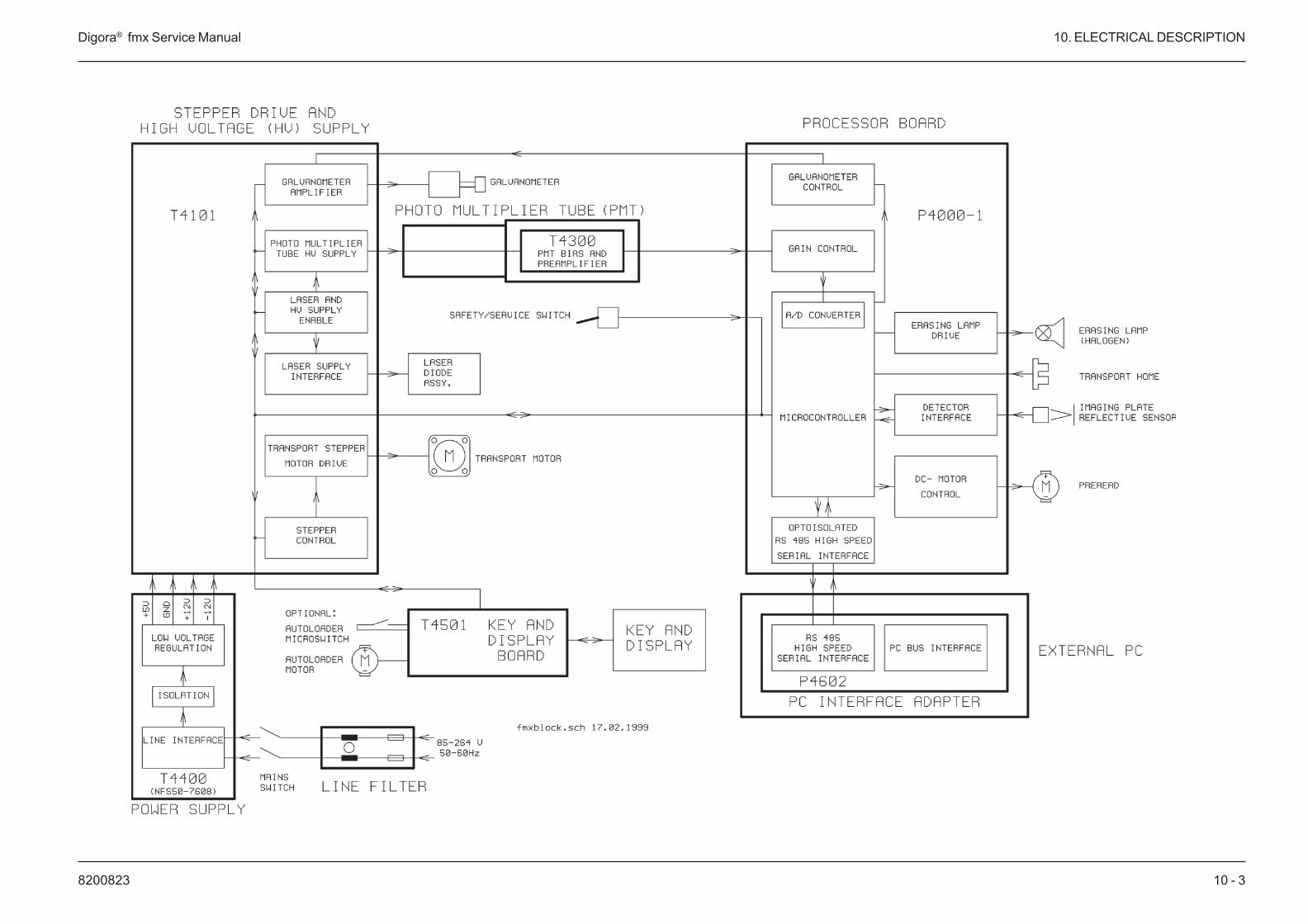
10. ELECTRICAL DESCRIPTION DXR-40 XXX-02Mains cord is connected to the power inlet of Digora. Power inlet includesthe mains filter and two line fuses. Mains voltage is connected to T4400Power Supply which generates supply voltages +5 VDC, -12 VDC and +12VDC. The supply voltages are lead through T4101 Stepper Drive and HVsupply pcb to P4000-2 Microprocessor board and T4501 Key and Displaypcb.
10.1 Functions connected to T4101 stepper drive and HVsupply PCBT4100 has electronics to generate high voltage to Photo Multiplier Tube. Thesignal coming from PMT is readby the P4000 pcb.
The laser diode assembly gets its +12 VDC supply voltage from T4101 aswell as control signal LASEREN for laser. When signal LASEREN goes low,the laser connected to the voltage supply will be turned on.
Transport stepper motor is driven by this board to move the imaging platehorizontally.
Galvanometer is provided to sweep the beam vertically over the imageplate. Sweep signal is controlled by microprocessor according to the resultsof calibration.
10.2 Functions connected to P4000-2 microprocessorPCBGround of all pcb's is connected to chassis.
Microprocessor of P4000 reads the signal level from preamplifier of T4300PMT pcb.
Transport home optical switch is used to stop the transport mechanismalways at the same place.
Reflective sensor detects the presence of the imaging plate. Scan startsautomatically when the imaging plate is inserted into the unit and the actionkey pressed.
Preread DC motor is provided to turn the preread lens into the laser beamat preread sequence of the scan. To turn the preread lens the motor is runfor a couple of seconds clockwise and after preread sequence anothercouple of seconds counter-clock-wise to move the lens off the beam. Me-chanical means are provided to limit the turn of preread lens.
12 V halogen lamp is provided for erasing the image plate after read out.
Safety switch is provided to block out laser and high voltage when equip-ment cover is removed.
A PC Interface adapter pcb is connected with interface cable to P4000 pcbby using RS485 interface protocol.

10. ELECTRICAL DESCRIPTION - DXR-40 XXX-03 Digora® fmx Service Manual
820082310 - 2
10.3 Functions connected to T4501 key and display PCBKeyboard/display as well as the optional Autoloader motor and positiondetector (microswitch) are connected into this pcb.
10.4 The PC boardsThe names and functions of all Digora PC boards are as follows:
P4000-1 Processor boardThis is the main PCB that contains the micro controller (Intel 80C198) thatcontrols the scanner, amplifier for the analog signal from the photomultipliertube, galvanometer control front end circuit, erasing lamp control,optoisolated RS485 serial port and driver for the pre-read DC-motor.
T4101 Stepper drive and HV supplyThis PCB contains a high voltage power supply for the photo multiplier tube,laser power supply control, galvanometer power amplifier and a controllerand a driver for the transport stepper motor.
T4300 PMT biasThis PCB contains a resistive voltage divider for the photo multiplier tube(PMT) biasing voltages and a preamplifier for the PMT signal. This PCB ispart of the PMT assembly.
T4400 Mains power supplyThis is a universal input switching mode power supply.
T4501 Key and displayThis PCP contains control for the keys and LEDs, a test jumper, connectorfor the autoloader motor and connector for the autoloader micro switch. ThisPCB is mounted behind the plastic front panel.
P4601 & P4602 Interface adaptersThese are the interface adapter board between Digora and the PC compu-ter.
10 - 38200823
Digora® fmx Service Manual 10. ELECTRICAL DESCRIPTION

820082310 - 4
10. ELECTRICAL DESCRIPTION Digora® fmx Service Manual

11 - 18200823
Digora® fmx Service Manual 11. PROCESSOR BOARD P4001 and P4000-2
11. PROCESSOR BOARDS P4001 AND P4000-2Processor board P4001 is the same as its predecessor (P-4000-2) exceptthat it has a different processor (Intel 80C196KC) and I/O addressing. Inaddition, some of the IC-circuits have been replaced with surface mounteddevices.Because the I/O addressing was changed, new software for the P4001was required. The software on P4001 is NOT interchangeable with thesoftware on P4000-2, and vice versa. For more information on the P4001software, refer to the section "Scanner Software".
The P4000-2 board is installed in units up to serial number G16234
The P4001 board is installed in units from G16235
This is the main PCB that comprises the micro processor that controls thescanner, amplifier for the analog signal from the photomultiplier tube, gal-vanometer control front end circuit, erasing lamp control, RS485 serialport and the driver for the pre-read DC-motors.
11.1 Functional description; Main Features:• Intel 80C196KC (P4001)/80C198 CPU (P4000-2), 32 kB external code
ROM, no external RAM• internal 10-bit 4-channel A/D converter• 750 kBd optoisolated serial RS485 interface to PC or compatible
computer• motor drive circuits for DC motors (preread motor)• photo multiplier signal amplifier with CPU controlled 2-stage gain control
and offset adjustment• photo multiplier high voltage power supply control DAC• galvanometer drive circuit (front end) with hardware protection mecha-
nism• imaging plate reflective sensor interface• transport home slotted optical switch interface• input connectors for several switches• separate +/-5 V and +/-8 V regulation for analog circuits• Internal watchdog circuit in CPU• 12V halogen lamp drive for erasing the imaging after readout

820082311 - 2
11. PROCESSOR BOARDS P4001 and P4000-2 Digora® fmx Service Manual
11.3 CPU interfaceCPU operating frequency is 12Mhz, which is further divided by 16 (IC2) tocreate a 750 kHz clock for internal timing purposes. This clock is con-nected to timer 2 input of CPU.
Both 32 kB (27256) and 64 kB (27512) EPROMs can be used. EPROM ismapped to the lower half of CPU address space.
All 1/0 is mapped to the upper half of CPU address space (addresses8000...FFFF).
11.3 Photo multiplier amplifierPMT amplified has a total maximum gain of 212. It has been built fromthree separate amplifier stages, which have gains of 1,53 and 4. Gain iscontrolled by a dual digital potentiometer between the stages. The first halfof the digital potentiometer can attenuate the signal down to 1/256, whilethe other half is used by the CPU to fine-tune the adjustment and can onlyattenuate the signal down to 128/256. Thus the minimum gain of the overallamplifier is about 0,41 (212/256 by 128/256). There is also a CPU control-led offset adjustment to eliminate PMT dark current.
The first amplifier stage (1C14/a) is a differential amplifier, which is con-nected as a normal non inverting amplifier by shorting JP1. The maximuminput allowed from PMT is around 4 volts. A typical maximum input fromPMT is around 2 volts when an x-ray dose equal to calibration dose isused. The first amplifier stage has a manual offset adjustment.
The second amplifier stage (IC14/b) has a gain of 53. It has two offsetadjustments. The manual adjustment range is +/-0,5 V and the CPU adjust-ment range (digital potentiometer) is 0 ... -1 V measured at TP4.Attenuator between the first and second stage can attenuate the signaldown to 1/256.Third amplifier has a gain of 4 and the attenuation can go down to 128/256.

11 - 38200823
Digora® fmx Service Manual 11. PROCESSOR BOARD P4001 and P4000-2
The positive power supply of the amplifiers is also the reference voltage ofthe A/D converter. This guarantees that the voltage at the A/D converterinput will never be greater than Vref. The negative power supply of the lastop-amp is at ground to prevent negative voltages in A/D converter input.
FIGURE 11 - 1: Photo multiplier amplifier block diagram - manual offsetadjustment not shown
11.4 Adjustment of manual potentiometersPotentiometer R40 is for compensating the offset voltage from the PMTtube preamplifier and the first premaplifier of IC14. Potentiometer R35 isfor compensating the offset voltages from the second and third amplifiersages os IC14 an IC23.
The manual potentiometers are adjusted at factory. To check the adjust-ment or re-adjust it, do as follows:
• Switch the power off, wait for a few seconds and switch it on again toreset the digital potentiometers to their default values.
• Make sure that the PMT unit is connected to connector J4008. Connectthe negative terminal of a DVM to analog ground at TP3 or TP12. Waitfor 2 minutes to allow the amplifier offsets to settle after power-on.
• Adjust R40 to get a 0 m V reading from TP10.• Adjust R35 to get a 50 mV reading from TP13.
Since the first stage offset adjustment is also used to compensateoffset errors of the amplifier on PMT assembly, the adjustment is onlyvalid when a tube assembly is present during adjustments. If the tubeassembly is to changed, adjustments must be done again.

820082311 - 4
11. PROCESSOR BOARDS P4001 and P4000-2 Digora® fmx Service Manual
11.5 Galvanometer driverThe galvanometer drive signal is a triangle wave, whose amplitude, DCoffset and frequency are adjustable. In practice only the amplitude (sweeplength) and DC offset (sweep position) are adjusted while the frequency(vertical line frequency) is kept constant.
FIGURE 11 - 2: Triangle wave form for sweeping the galvanometer
The galvanometer signal is generates with an integrator (1C26/a). threedifferent voltage levels are switched to integrator input with analog switches(!C20, 25) and the integrator capacitor is disharged with switch IC25/c.
CPU generates all signal transitions by controlling the integrator switchescontinuously during plate readout:
1 Vertical sweep: negative voltage is integrated about 20 ms (INT_POSactive)
2 Sweep return: positive voltage is integrated about 4 ms (INT_NEG ac-tive)
3 Integrator is cleared momentarily (INT_CLEAR active) when about half ofthe sweep return has taken place. DC offset is adjusted bycontrolling the precise timing of clearing in respect to the sweep return.
4 Galvanometer stabilisation time: zero volt signal is integrated about6 ms (INT_0 active)
The CPU controls the signal amplitude by writing the digital potentiometer(IC21), which sets integrator input voltages. Changing integrator inputvoltages affects the output amplitude when frequency is kept constant. Boththe positive and negative slope of the triangle wave are controlled by thesame digital potentiometer output. The resulting adjustment range for pin 7of IC26 is -0,5 ... -1 V (INT_POS) an for pin 7 of IC8 it is 2.5 ... 5 V(INT_NEG).
The signal for INT_NEG (2.5 ... 5 V) is also accessible to the A/D converteras GAL_TEST. At present the A/D converted only measures it as the inputsignal for the Scanner Test Image (available when Digora Service Assistantis used).
The integrator signal amplitude and DC offset are changed according to the

11 - 58200823
Digora® fmx Service Manual 11. PROCESSOR BOARD P4001 and P4000-2
results of the calibration procedure activated by the user.
Wen the galvanometer is not used, CPU keeps the integrator continuouslycleared and disables all other control signals. This keeps the integratoroutput at zero volts. If the integrator clearing signal is not active for any rea-son, the integrator begins to integrate its own offset voltage and output isdriven towards either of the supply voltages, which causes excessive heatingof the galvanometer and its power driver. This is prevented with a protectioncircuit, which monitors the integrator output. If the output signal is continu-ously greater than +/- 4 V, it opens an analog switch (IC20c or d) that con-nects the integrator output to the power driver.
FIGURE 11 - 3: Galvanometer control circuitry, simplified block diagram

820082311 - 6
11. PROCESSOR BOARDS P4001 and P4000-2 Digora® fmx Service Manual
11.6 Plate detectorThe plate detector is used to sense if an imaging plate is inserted properlyor not. The plate detector is an optical reflective IR sensor, which gives ahigh signal if the white side of a plate is towards it. If a plate is inserted thewrong way or is not present, the signal is smaller. Due to the mechanicalassembly, reflector sensitivity variations, sensor aging and temperaturedrift the scanner adjusts the sensitivity of the plate detector in run time.
The detector consists of a transmitter and a receiver. The transmitter LEDcurrent is adjusted by a voltage controlled current generator (IC27/c, R62and TR3). The LED current is set by IC21. the maximum current is 3mA.The current generator is enabled with the PLATEDET* signal, otherwisethe current is zero to prevent the LED light from erasing the image fromthe imaging plate before readout. The LED current is at maximum by de-fault, but if this gives too high a receiver signal, the current is decreased.The PLATEDET* signal activity is connected to safety/service switch posi-tion. When the switch indicates that the scanner cover is open (laser andhigh voltage supply can't be activated), the PLATEDET* signal is on con-stantly to make it easier to measure the plate detector signals. When theswitch is turned to the other position, the PLATEDET* signal is on only inshort pulses (about 20 ms each) and only when absolutely needed toprotect the image in the imaging plate.
The receiver is a photo transistor, whose output signal is buffered andlimited with IC27/a and can be read with the A/D converter.

11 - 78200823
Digora® fmx Service Manual 11. PROCESSOR BOARD P4001 and P4000-2
11.7 Test pointsTP1 Digital +5V supplyTP2 Digital groundTP3 Analog groundTP4 PMT signal after second amplifier (gain 53) and first attenuator
(1 ... 255 /245)TP5 Analog -8VTP6 Analog +8VTP7 Analog -5VTP8 Analog +5V (A/D ref)TP9 Galvanometer integrator outputTP10 PMT signal after first amplifier stage (gain 1)TP11 INT_CLEAR, galvanometer integrator clear signalTP12 Analog groundTP13 FINALPMT, amplified PMT signal to A/D converterTP14 HV_REF, analog high voltage control signalTP16 Plate detector LED current,TP18 TcD/RxD* RS485 transceiver direction control from CPUTP19 RxD from RS485 transceiverTP20 TxD from CPUTP21 TEST, pixel clock for A/D conversionsTP23 Digital groundTP24 Digital ground
11.8 Led indicatorsPower supply indicators (always active)D1 Analog -8VD2 Analog +8VD3 Analog -5VD4 Analog +5V (Vref)D12 High voltage on (see notes)
The rest of LED indicators are active only when the safety/service switchis in upper positionD11 Service (safety/service switch active)D13 Laser activeD10 TxD, flickering indicates RS485 activityD9 RxD, flickering indicates RS485 activity
NOTES:High voltage power supply and laser are always disabled when the scan-ner cover is removed. If these circuits need to be activated for test pur-poses, the safety/service switch should be set to down position. The highvoltage LED indicates that CPU is trying to activate the circuit, but if theservice switch is in the upper position, it cannot be done.
On the high voltage supply board T4101 there is another LED, which givesreal indication whether the high voltage is active or not.

820082311 - 8
11. PROCESSOR BOARDS P4001 and P4000-2 Digora® fmx Service Manual
11.9 P4000-2 connector pinoutsJ4001
1, 3, 5, 7, 8, 9 AGND - -12, 14, 17,18, 19 +12V in -15,16 -12V in -20, 38, 39 +5V in -28, 36, 37 GND - -2 HV_FB in analog feedback signal from
hv power supply4 HV_REF out analog high voltage control
signal, 5V=850V6 GAL_sweep out galvanometer drive signal to
power amplifier10 TEST out pixel clock for A/D conver-sions11 HV_OFF out hv power supply on/off con-trol from CPU13 HV_ENA out high voltage enable (from
safety/service switch)21 SEAMENA* out seamer drive enable fro CPU22 COMP_HOME* in seamer compression motor
is at start position23 SEAMREQ* in front panel seamer pushbutton24 DOOR_HOME* in door micro switch to indicate
of door is open25 SMALL out LED output for small plate
indocator LED26 SMALL in small push button in frontpanel27 RUN* in front panel test push button29 COMP out connect stepper driver to
seamer motor, active whenseamer motor is running
30 SLIDE out connect stepper driver toplate movement motor, activewhen plate movement
motor is running31 STEPCLK out clock for plate movement
motor and seamer stepper32 STEPENA* out stepper driver enable33 LEVELPRO out stepper motor operationmode34 STEPENA* out stepper rotation directioncontrol35 SLOWCD out control signal for slowcurrent decay mode ofstepper motor40 LASER* out enables laser

11 - 98200823
Digora® fmx Service Manual 11. PROCESSOR BOARD P4001 and P4000-2
J40021 BUSS_B i/o RS485 signal line2 BUSS_A i/o RS485 signal line3 PCGND - PC ground for isolated RS4854 +5C_PC in RS485 power supply from PC
J40031 PRER_ out preread lens motor drive signal2 AGND -
J40041 LIFT_MOT out plate lift motor drive signal2 AGND - -
J40051 PLATE in signal to indicate reflectiveness of mate-rial in front of reflective sensor2 - out low when reflective sensor is activated,this signal is high when presense ofimaging plate is detected3 GND - -4 - out supply voltage for LED
J40061 HOME in signal to indicate when the imaging plate
transport motor is at start position2 GND - -3 GND - -4 - out supply voltage for LED
J40071 LAMP_GND out open collector output for plate eraselamp2 +12v - -
J40081,2,7,8 nc. -3 +8V - +8V supply voltage4 AGND - -5 PMT_OUT in analog signal from photo multiplier tube6 -8V - -8V supply voltage

820082311 - 10
11. PROCESSOR BOARDS P4001 and P4000-2 Digora® fmx Service Manual
J40091 GND - -2 HV_ENA* in safety/service switch to disable hv andlaser when cover is openJF - ground point of secondary circuit
*) = indicates that signal is active LOW, all other signals are active HIGH

11 - 118200823
Digora® fmx Service Manual 11. PROCESSOR BOARDS P4001 and P4000-2
P4001 Processor board, circuit diagram (Sheet 1/4)

820082311 - 12
11. PROCESSOR BOARDS P4001 and P4000-2 Digora® fmx Service Manual
P4001 Processor board, circuit diagram. (Sheet 2/4)

11 - 138200823
Digora® fmx Service Manual 11. PROCESSOR BOARDS P4001 and P4000-2
P4001 Processor board, circuit diagram. (Sheet 3/4)

820082311 - 14
11. PROCESSOR BOARDS P4001 and P4000-2 Digora® fmx Service Manual
P4001 Processor board, circuit diagram. (Sheet 4/4)
11 - 158200823
Digora® fmx Service Manual 11. PROCESSOR BOARDS P4001 and P4000-2
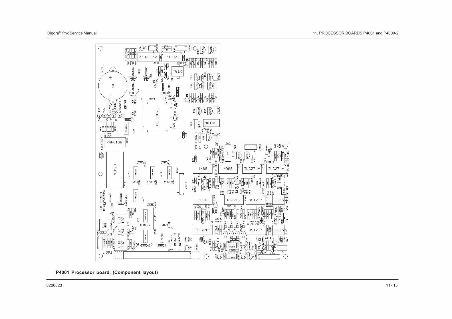
P4001 Processor board. (Component layout)

820082311 - 16
11. PROCESSOR BOARDS P4001 and P4000-2 Digora® fmx Service Manual
P4000-2 Processor board, circuit diagram (Sheet 1/4)

11 - 178200823
Digora® fmx Service Manual 11. PROCESSOR BOARDS P4001 and P4000-2
P4000-2 Processor board,circuit diagram (Sheet 2/4)

820082311 - 18
11. PROCESSOR BOARDS P4001 and P4000-2 Digora® fmx Service Manual
P4000-2 Processor board, circuit diagram (Sheet 3/4)

11 - 198200823
Digora® fmx Service Manual 11. PROCESSOR BOARDS P4001 and P4000-2
P4000-2 Processor board, circuit diagram (Sheet 4/4)

820082311 - 20
11. PROCESSOR BOARDS P4001 and P4000-2 Digora® fmx Service Manual
P4000-2 Processor board (Component layout)Processor board P4000-2 is identical to P4000-1 except that connector J4007 has been changed to AMP MOD 1 type.For this reason P4000-1 and 4000-2 are not interchangeable without changing the erasing lamp connector. Also additional jumper wires have been implementented in the PCB design.

12 - 18200823
Digora® fmx Service Manual 12. PROCESSOR BOARD P4100 DXR-40 XXX-02
12. STEPPER DRIVE AND HIGH VOLTAGE SUPPLYT4101
This PCB contains a high voltage power supply for the photo multiplier tube,a single stepper controller, laser tube power supply control, galvanometerpower amplifier and a driver for the transport stepper motor.
12.1 Functional description
Main features• CPU controlled high voltage supply for photo multiplier tube• galvanometer power amplifier• micro stepper contoller interface and power amplifier for imaging plate
movement motor• laser On/Off control
12.2 High voltage power supply
Specifications:Voltage range -350 ... -880 VDC
Output current max. 1 mA
Ripple 50 mVpp (When noise at HV_REF<100 uV)
Line regulation 0.05 %
Output voltage of high voltage supply is set by CPU DAC with HV_REFsignal. Supply is stable with a 1Mohm load in the voltage range of -350 ... -880V. Voltage range is set with resistor R1+R2+R3/R6+R7, and a controlsignal of 5 volts is equal to -880V output voltage. If output is set to a voltageless than -350 volts, ripple is not within specified limits. The output is currentlimited and short circuit protected.
UC3846 PWM controller has two totem pole outputs, one them drives a fetcontrolling the transformer and other is connected to a led, which indicates ifthe high voltage supply is active.
Input power of the high voltage supply is stabilised to 9.8 volts with IC3 toimprove line regulation.

820082312 - 2
12. PROCESSOR BOARD P4100 DXR-40 XXX-02 Digora® fmx Service Manual
12.3 Control signalsHV_REF analog input, sets output voltage
HV_FB analog output, read back of output voltage for 5V = -880V
HV_OFF input on/off control signal from CPU
HV_ENA input, on/off from safety/service switch
Truth table of HV_ENS and HV_OFF:
HV_ENA HV_OFF hv output0 0 disabled0 1 disabled1 0 enabled1 1 disabled
12.4 Micro stepper interfaceMicro stepper controller drives stepper motors by controlling motor windingcurrents resulting in one motor step being divided into 32 parts. This meansthat with a 200 step motor, one revolution is equal to 6400 microsteps. Microstepper circuit is driven by CPU with following control lines:
STEPENA* Controls stepper current on/off
STEPDIR Sets rotation direction
STEPCLK Step pulse input: each rising edge moves motor with onmicrostep
LEVELPRO Selects power amplifier operating mode, fast or slow. Fastmode allows fast current transitions in stepper windings. Itmay be used when very fast speed is required. Fastmode is currently not used
SLOWCMD Forces power amplifier to slow mode overriding theLEVELPRO setting
TEST Synchronises power amplifier chop per frequency with A/Dconversion frequency
COMP/SLIDE These signals can be used to select between two steppermotors. When imaging plate movement motor is used,SLIDE signal is active.
Controller is built from a 8bit up/down counter (IC9,11), which keeps track of

12 - 38200823
Digora® fmx Service Manual 12. PROCESSOR BOARD P4100 DXR-40 XXX-02
a current step position and provides address inputs for an EPROM, wheremotor current tables are stored. EPROM data outputs drive a dual D/Aconverter (IC/10) which sets power amplifier (IC/7) output currents for bothmotor windings. Maximum output current is set with current measurementresistors R34 ... R37 and is 650 mA.
12.5 Test pointsTP1 analog groundTP2 -9.8V for hv supplyTP3 CLOCKW, galvanometer outputTP4 +12V (for analog circuits)TP5 analog groundTP6 -12VTP7 DIGITAL GROUNDTP8 stepper power stage mode control input, phase 1TP9 stepper current sense, phase 1TP10 +12V for stepperTP11 stepper current polarity input, phase 2TP12 stepper power stage mode control input, phase 2TP13 analog input, phase 2 stepper currentTP14 stepper current sense, phase 2TP15 stepper chopper oscillatorTP16 stepper current polarity input, phase 1TP17 DIGITAL GROUNDTP18 analog input, phase 1 stepper currentTP19 +5v

820082312 - 4
12. PROCESSOR BOARD P4100 DXR-40 XXX-02 Digora® fmx Service Manual
12.6 Laser and photomultiplier high voltage controlIn normal operating state the HV_ENA signal from the safety/service switchis high, the PMT high voltage power supply follows the HV_REF voltage andlaser power supply con be enabled or disabled by the LASERENA signal.
Input voltages for the LASER power supply (LASER +12v andLASER_GND) are connected directly to the scanner power supply by dedi-cated wires and the LASEREN* signal is optoisolated.

12 - 58200823
12. STEPPER DRIVE AND VOLTAGE SUPPLY T4100 Digora® fmx Service Manual
Circuit Diagram for T4101 Stepper drive and high voltage supply (Sheet 1/3)

820082312 - 6
12. STEPPER DRIVE AND VOLTAGE SUPPLY T4100 Digora® fmx Service Manual
Circuit Diagram for Stepper drive and high voltage supply T4101 (Sheet 2/3)

12 - 78200823
12. STEPPER DRIVE AND VOLTAGE SUPPLY T4100 Digora® fmx Service Manual
Circuit Diagram for Stepper Drive and high voltage supply T4101 (Sheet 3/3)

820082312 - 8
12. STEPPER DRIVE AND VOLTAGE SUPPLY T4100 Digora® fmx Service Manual
Component layout for T4101 Stepper drive and high voltage supply (Component layout)

13 - 18200823
Digora® fmx Service Manual 13. PMT BIAS 74300
13. PMT BIAS T4300This PCB contains a resistive voltage divider for the photo multiplier tube(PMT) biasing voltages and a preamplifier for the PMT signal. This PCB ismounted inside the PMT assembly and is a part of the actual PMT. Theprincipal of this PCB is described in the following description.
13.1 Photomultiplier tube biasingPMT operating voltage (-HV) is adjusted by the micro controller betweenapproximately -400 to -800V depending on the x-ray dose of the calibrationimage. This voltage is divided evenly between PMT dynodes by resistors R1... R10.
13.2 PMT signal preamplifierCurrent from the PMT anode is converted to voltage (PMT_OUT by opampIC1. Its gain can be adjusted by trimmer R15 to compensate for varyingsensitivities between PMTs.
PMTs are supplied as complete units including the tube and a factory ad-justed preamplifier.

820082313 - 2
13. PMT BIAS 74300 Digora® fmx Service Manual
13.3 T4300 Circuit Diagram for photomultiplier

13 - 38200823
Digora® fmx Service Manual 13. PMT BIAS 74300
13.4 T4300 Component layout for photomultiplier

820082313 - 4
13. PMT BIAS 74300 Digora® fmx Service Manual

14 - 18200823
Digora® fmx Service Manual 14. MAIN POWER SUPPLY T4400
14. MAINS POWER SUPPLY T4400
T4400 is a standard power supply NFS50 type 3223 or equivalent. T4400can be connected to any mains supply voltage from 100 VAC to 240 VAC.
Connector pinouts (NFSSO type 3223):
T4400/J2(nc.) -12 V -12 Supply Voltage2 +12 V +12 V Supply Voltage for laser3 GND Ground Potential for laser4 +5 V +5 V Supply Voltage
T4400/J31 -12 V -12 V Supply Voltage for galvanometer power amplifier2 +12 V +12 V Supply Voltage for galvanometer power
amplifier3 GND Ground Potential for galvanometer(nc.) +5 V +5 V Supply Voltage
T4400/J4(nc.) -12 V -12 V Supply Voltage2 +12 V +12 V Supply Voltage3 GND Ground Potential4 +5 V +5 V Supply Voltage
Connector Pinouts (PM65-31A):1 +5 V +5 V Supply Voltage2 +5 V +5 V Supply Voltage3 GND Ground Potential4 GND Ground Potential5 +12 V +12 V Supply Voltage6 +12 V +12 V Supply Voltage7 -12 V +12 V Supply Voltage8 NC

820082314 - 2
14. MAIN POWER SUPPLY T4400 Digora® fmx Service Manual

15 - 18200823
Digora® fmx Service Manual 15. KEY AND DISPLAY T4501
15. Key and display T4501
This pcb contains all the electronics necessary for the membrane keyboard/LED display connected to J4502. It also contains the circuitry to move andcontrol the autoloader motor.
Run (Action) Led is blinking when signal STEPENA is high. The circuitrycontrolling the blinking frequency is made by IC2 (two gates), resistors andcapacitor C1. The other half of IC1 is used to allow the CPU to read eitherjumper J2 (mode) or autoloader microswitch signal through one single signal(COMP_HOME). When STEPENA is in L state, CPU can read the state ofMODE jumper (no jumper means normal unit, with jumper means that unithas an Autoloader option) and when STEPENA is H, CPU can read theautoloader microswitch signal.
Jumper J1 (Run) is provided for testing purposes. When jumper is inserted,the scanner performs continously the scanning sequence using the internalreadout values (not the values of calibration) and also therefore the connec-tion to the PC is not necessary. Autoloader is not functionable when jumper isinserted in J1.
Connector Pinouts
J4501
1-6 AGND GND to the circuitry7 MOTENA* IN when L, activates the autoloader
motor8 COMP_HOME* OUT L active signal, presence of
mode jumper or autoloadermicroswitch connecting
9 SEAMREQ* OUT goes L when Action button ispressed
10 DOOR_HOME OUT11-14 no connection15 STEPENA IN controls the Action led blinking
and select switch to be moni-tored
16 SMALL IN controls which of image sizeLEDs is ON
17 SMALL1 OUT goes H when image size buttonis pressed
18 RUN* OUT goes L whem jumper is insertedin J1
19-20 +12V +12Vdc supply voltage to thecircuitry

820082315 - 2
15. KEY AND DISPLAY T4501 Digora® fmx Service Manual
J4502pin signal dir Description1 PE shield of keyboard
2 RUN_LED OUT controls the ACTION led on themembrane keyboard
3 AGND GND to the POWER ON LED onmembrane keyboard
4 START* IN goes L when Action button ispressed
5 AGND GND to membrane keyboard
6 OUT when L switches on the smalllsize LED
7 OUT when L switches on the normalsize LED
8 SMALL1 IN goes H when image sixe buttonis pressed
9 DOOR_HOME no connection10 +5Vdc
J45031 OUT autoloader dc motor connection2 OUT autoloader dc motor connection
J45041 ALHOME* OUT when L enables autoloader
microswitch to be monitored2 COMP_HOME IN goes L, when autoloader
microswitch is enabled andactivated

15 - 38200823
KEY AND DISPLAY T4501 Digora® fmx Service Manual
Circuit Diagram for Key and Display T4501

820082315 - 4
15. KEY AND DISPLAY T4501 Digora® fmx Service Manual
Component layout for Key and Display T4501

16 - 18200823
Digora® fmx Service Manual 16. PC INTERFACE ADAPTER P4601
16. PC interface adapters16.1 P4602
PC Interface Adapter P4602 is a interface board between the scanner andcomputer and it is installed in the PCI bus of the computer. It consist ofconfigurable FPGA circuit which reads its configuration, the program, from aserial EPROM. The FPGA circuit takes care of the interfacing to the PCI busand all the UART (asyncronous receiving and transceiving) functions re-quired. RS485 circuit and filtering are provided for proper interfacing to theDigora scanner. This board requires DfW 2.0 (revision 2 or later) to beinstalled in the PC.
16.2 P4601This is the interface adapter board between the scanner and the computerand it is installed in the ISA bus. This pcb is basically a semi-intelligent bi-directional serial transfer buffer with 2 kilobytes of dual port RAM.
16.2.1 Micro controller and dual port ramThe micro controller 1C7 (Intel 80C198) controls data transfer betweenscanner and PC/AT using a 2kx8 dual port RAM IC8. This dual port RAMhas two separate address, data and control busses, which enables asyn-chronous access to any memory location via both busses. If both bussesrefer to same memory location, the control logic sets the BUSY* signal forthe delayed bus.
One side of the dual port RAM is connected to PC/AT bus and the otherside via the processor's serial port to the scanner. This RAM functions as adouble line buffer between scanner and PC/AT.
The Interface Adapter board's base 1/0 address can be selected between100h ... 3F8h with increments of eight consecutive 1/0 memory locations.
16.2.2 Interface board connection for opto couplersThe opto couplers are included in the P4000-2 processor board to provideground isolation between the scanner and the PC. This ground isolationdecreases the chances of electrical interference to the scanner from the PC.Ground isolation is also required for the Digora scanner to be compatiblewith the requirements of IEC601-1.

820082316 - 2
16. PC INTERFACE ADAPTER P4601 Digora® fmx Service Manual
16.2.3 Control SignalsTP3 STATUS Informs PC/AT of valid data in dual port RAM.
TP8 TOGGLE Memory page toggle at PC/AT side of dual portRAM.
TP7 PENDING Informs the micro controller of data being writtento dual port RAM by PC/AT.
TP5 READY Informs the micro controller of valid data in dualport RAM
FIGURE 16 - 1: Control Signals

16 - 38200823
Digora® fmx Service Manual 16. PC INTERFACE ADAPTER P4601
16.2.4 Test pointsTP1 ADRMATCH* Address set for this board matches the address
on the PV address bus(signal is shorter than 1 us).
TP2 10_ACCESS Read of Write access in 1/0 address space onthe bus. (This interface board is accessed onlywhen both ADRMEATCH* and 10_ACCESS areactive.)
TP3 STATUS Valid data for PC in dual Port RAM.
TP4 CE_L Chip Enable for Dual Port RAM from PC bus.
TP5 READY Valid data for local CPU in Dual Port RAM.
TP6 CE_R Chip Enable for Dual Port RAM from local CPU.
TP7 PENDING Data is being written to Dual Port RAM by PC.
TP8 TOGGLE Selection between page 0 and page 1 of DualRAM by PC.
TP9 COM_ERR* Communication error detected by PC(not in use).
TP10 BUSYL* Wait state request to PC bus.
TP11 BUSYR* Wait state request to local CPU
TP12 TXD/RXD* Direction of RS485 bus.
TP13 TXD TxD of local CPU.
TP14 RXD RxD of local CPU
TP15 +5V Positive supply from PC bus
TP16 GND

820082316 - 4
16. PC INTERFACE ADAPTER P4601 Digora® fmx Service Manual
16.2.5 CONNECTOR PINOUTS J4601 (to PC bus)PIN SIGNAL DESCRIPTION1 nc2-9 AT - D7-D0 Low byte of AT data bus10 IOCHRDY I/O channel ready to AT bus11 AT-AEN Address enable from AT bus12-21 nc22-31 AT - AD9-AD0 10 lowest bits of AT ADDRESS BUS32 GND -33 RST Reset from AT bus34 +5 V Supply voltage from AT bus35-40 nc41 GND -42, 43 nc44 IOW* I/O write cycle from AT bus45 IOR* I/O read cycle from AT bus46-61 nc62 GND -
16.2.6 CONNECTOR PINOUTS J4602 (to Digora rear panel)
PIN SIGNAL DESCRIPTION1 BUSS_A One signal line of RS485 bus2-4 nc5 GND6 nc7 BUSS_B Other signal line of RS4858 nc9 +5 V Supply voltage to opto isolated parts of
Digora

82008231 16 - 5
Digora® fmx Service Manual 16. INTERFACE ADAPTERS
P4602-1 Circuit Diagram for Interface Adapter
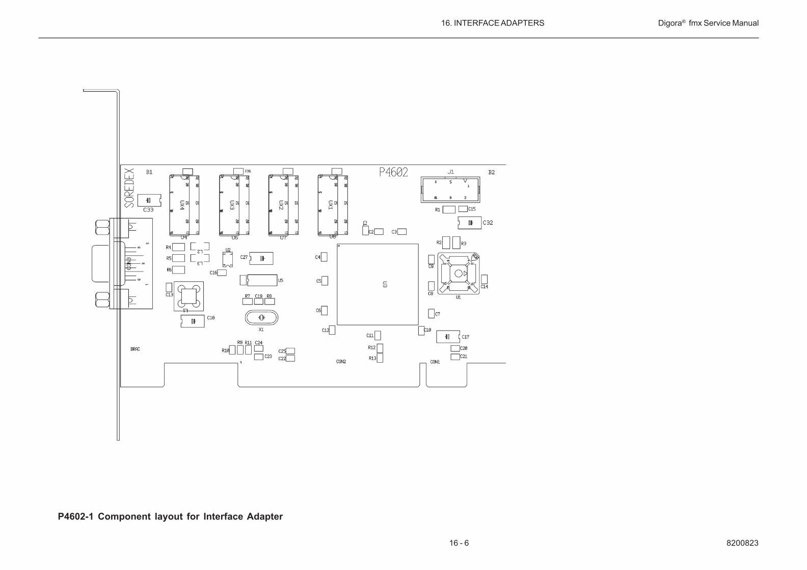
16 - 6 8200823
16. INTERFACE ADAPTERS Digora® fmx Service Manual
P4602-1 Component layout for Interface Adapter

82008231 16 - 7
Digora® fmx Service Manual 16. INTERFACE ADAPTERS
P4601 Circuit Diagram for Interface Adapter

16 - 8 8200823
16. INTERFACE ADAPTERS Digora® fmx Service Manual
P4601 Component layout for Interface Adapter

17 - 18200823
Digora® fmx Service Manual 17. SCANNER SOFTWARE
17. SCANNER SOFTWARE
The microcontroller on the P4001/P4000-2 board controls all the functionsof the scanner. It communicates with the PC interface board which linksthe communication to the Digora for Windows software running in PC.
The microcontroller software resides in an EPROM circuit labelled P4001/P4000. Software versions 4.0x/3.0x are used with P4601 (ISA) surfaceboards and versions 4.1x/3.1x with P4602 (PCI) interface boards.
Since the scanner has no image buffers, it must immediately send all imagedata to the interface board. In normal operation, the scanner reads imagingplates only if Digora for windows allows it (that is , when the transport unithas stopped), the scanner software checks the states of the scannerswitches (action button, image size selector button, test switch, safety/serv-ice switch) and responds to their changes.
The scanner software responds to the connection tests of Digora for Win-dows also while it moves the transport mechanism as soon as the actualreadout has ended. The scanner software responds to the functions ofDigora Service Assistant only when the scanner is idle.
17.1 Timing of the main functions
17.1.1 Power-on sequence consists of:• initializing the preread lens position (0.1 s)• driving the imaging plate holder inwards pass the slotted optical switch
(5s)• initializing the reflective sensor sensitivity data (0.1 s)• returning the imaging plate holder completely out (7 s)• imaging plate holder remains in this position if imaging plate is present in
the holder.• driving the imaging plate holder inwards as long as the door closes (2 s)
17.1.2 Image readout sequence consists of:• premove of the imaging plate holder (1 s)• preread of the imaging plate (4 s)• actual image readout (16 s)• move to the erasing area (2 s)• erasure of the residual image (4 to 44 s depending on the High voltage
setting and the signal read from imaging plate)• return to the slotted optical switch (2 s)• pushing the imaging plate holder to its outmost position if the scanner
door is open and if there is an imaging plate in the holder (2 s).

820082317 - 2
17. SCANNER SOFTWARE Digora® fmx Service Manual
17.1.3 Calibration sequence consists of:• premove of the imaging plate holder (17 s)• preread of the imaging plate (18 s)• actual image readout (16 s)• move to the erasing area (2 s)• erasure of the residual image (4 to 44 s depending on the High Voltage
setting and the signal read from imaging plate)• return to the slotted optical switch (2 s)• pushing the imaging plate holder to its outmost position if there is an
imaging plate in the holder (2 s)
17.2 Software versions
Versions 3.00 and 3.10
Original software versions of Digora fmx. 3.0x version is for scanners whichare connected with ISA interface board (P4601) to the PC and 3.1x versionis for scanners which are connected with PCI interface board (P4602) to thePC.
Versions 3.01 and 3.11
These software replaces the original versions. The changes are:
- The acceptable values of calibration parameter Horizontal Length islimited to start from 4000. Originally the minimum value for thisparameter was 3000. Refer to chapter Calibration and Adjustment.
- The software has been made mode error tolerant when receivingmessages from the PC. It is strongly recommended that all units havingthe Autoloader option have this (or newer) software installed.
Versions 4.01 and 4.11These software versions are used with processor board P4001 (versions3.01 and 3.11 are used only with processor board P4000-2).Software version 4.01 and 4.11 function in exactly the same way as ver-sions 3.01 and 3.11, but they are NOT interchangeable, for example ver-sions 4.01 and 4.11 CANNOT be used with the P4000-2 processor board,and versions 3.01 and 3.11 CANNOT be used with the P4001 processorboard.
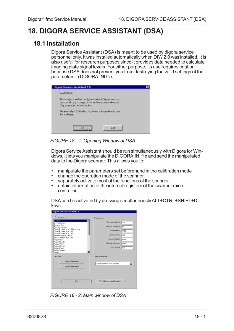
18 - 18200823
Digora® fmx Service Manual 18. DIGORA SERVICE ASSISTANT (DSA)
18. DIGORA SERVICE ASSISTANT (DSA)18.1 Installation
Digora Service Assistant (DSA) is meant to be used by digora servicepersonnel only. It was installed automatically when DfW 2.0 was installed. It isalso useful for research purposes since it provides data needed to calculateimaging plate signal levels. For either purpose, its use requires cautionbecause DSA does not prevent you from destroying the valid settings of theparameters in DIGORA.INI file.
FIGURE 18 - 1: Opening Window of DSA
Digora Service Assistant should be run simultaneously with Digora for Win-dows. It lets you manipulate the DIGORA.INI file and send the manipulateddata to the Digora scanner. This allows you to:
• manipulate the parameters set beforehand in the calibration mode• change the operation mode of the scanner• separately activate most of the functions of the scanner• obtain information of the internal registers of the scanner micro
controller
DSA can be activated by pressing simultaneously ALT+CTRL+SHIFT+Dkeys.
FIGURE 18 - 2: Main window of DSA
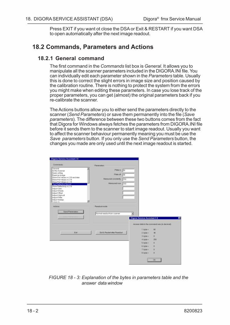
820082318 - 2
18. DIGORA SERVICE ASSISTANT (DSA) Digora® fmx Service Manual
Press EXIT if you want ot close the DSA or Exit & RESTART if you want DSAto open automatically after the next image readout.
18.2 Commands, Parameters and Actions
18.2.1 General commandThe first command in the Commands list box is General. It allows you tomanipulate all the scanner parameters included in the DIGORA.INI file. Youcan individually edit each parameter shown in the Parameters table. Usuallythis is done to correct the slight errors in image size and position caused bythe calibration routine. There is nothing to protect the system from the errorsyou might make when editing these parameters. In case you lose track of theproper parameters, you can get (almost) the original parameters back if youre-calibrate the scanner.
The Actions buttons allow you to either send the parameters directly to thescanner (Send Parameters) or save them permanently into the file (Saveparameters). The difference between these two buttons comes from the factthat Digora for Windows always fetches the parameters from DIGORA.INI filebefore it sends them to the scanner to start image readout. Usually you wantto affect the scanner behaviour permanently meaning you must be use theSave parameters button. If you only use the Send Parameters button, thechanges you made are only used until the next image readout is started.
FIGURE 18 - 3: Explanation of the bytes in parameters table and theanswer data window

18 - 38200823
Digora® fmx Service Manual 18. DIGORA SERVICE ASSISTANT (DSA)
18.2.2 Function commandsAll other commands in the Commands list box are DSA functions. Theyallow you to separately activate most of the functions of the scanner and toobtain information of the internal registers of the scanner micro controller.The scanner only responds to the functions when it is not busy. All the func-tions are described later in this chapter. When you select any of these func-tions, the Save parameters button turns gray since you can only send thesefunction commands to the scanner with the Send Parameters button.
The parameters relevant to each of these functions are shown in the Param-eters table. You can edit each of them but the system is not protected fromout-of-range values of these parameters. Any editing you make to theseparameters is lost when you exist DSA. Editing is NOT lost as long as youwitch between Digora for Windows and DSA without exiting DSA.
In case the function gives answer data from the scanner, there are always 8bytes of data in the answer. If the scanner is busy when you send the param-eters to it, no answer data is displayed. Only a few first ones of the answerdata bytes are meaningful. The contents of those bytes are explained in thefunction descriptions later in this chapter. The answer byte contents and theirtypical values are also shown as parameters in the Parameters table ofthose functions.
You can edit the DSA.DAT file with Notepad or other ASCII editor to makepermanent changes to the DSA functions or to change the order they appearin the Commands list box. The changes take place when you re-openDigora Service Assistant after editing and saving the DSA.DAT file. Again,there is nothing to protect the system from the error you make while editing.
18.3 Readout modesBy pressing the Readout modes button you can open a dialog box thatallows you to set the type of readout the system does after the readout com-mand is given.
Normally the readout command is given by pressing the Action key. Formaintenance purposes it is also possible to give the readout command fromthe keyboard. This can be done (when the scanners idle) by pressing simul-taneously four keys: Control, Alt, Shift and R (R for Read). Image plate shouldbe in place and image plate holder in image plate insertion position. Thecombination is difficult to make because the user should not start the imagereadout this way.
FIGURE 18 - 4: The readout modes window

820082318 - 4
18. DIGORA SERVICE ASSISTANT (DSA) Digora® fmx Service Manual
For normal use, only the mode Normal readout from scanner is needed.Take caution to remember to set the mode back to Normal readout after youhave used other modes:
• If any other mode is set while calibration is activated, the calibrationprocedure will fail.
• If any of the test image modes is set and the scanner is activated aftera new imaging plate has been inserted into the scanner, the system willenter a closed loop: Digora for Windows reads continuously new imagesas soon as it can since the scanner keeps on asking for an imagereadout. You can interrupt this loop by switching the scanner off. Thiscancels the image readout request from the scanner.You can use the test image modes to test the communication betweenDigora for Windows, the super VGA display driver software, the interfaceboard and the scanner:
• Test image from memory displays horizontally divided pieces of grayscales. This might be useful for checking the basic functionality of theSuper VGA driver.
• Test image from scanner displays an even gray image. The shade of thegray depends on the parameter Horizontal Minus. The image is built withthe same speed as during normal image readout. This image is built withthe same speed as during normal image readout. This mode is useful forchecking the communication from the scanner Digora for Windowswithout using imaging plates.
• Normal readout from scanner is used for normal operation.

18 - 58200823
Digora® fmx Service Manual 18. DIGORA SERVICE ASSISTANT (DSA)
18.4 Function descriptionsThe basic use of the functions is described earlier in this chapter under theheading Function commands of Commands, Actions and Parameters.
The (bracketed numbers) after function parameters are default values. If youedit the parameters, use the allowed values only. Don't use negative param-eter values. The allowed values are believed to be functional but they are notthoroughly tested.
The (bracketed numbers) after reply values are typical replies.
Init the Scanner:• Parameters: none• Reset the scanner to its initial status exactly the same way as after
power on.
Seam a Bag:• Parameters:none• In older Digora models this executes the full seaming procedure exactly
the same way as ifthe seaming button had been pressed.• In Digora fmx model this moves the Autoloader motor one step forward.
Read an Image:• Parameters:none• Activates the scanner for normal readout exactly the same way as if the
Test button (on the P4500 board) had been pressed. The readout modesetting of DSA has no effect with this function. Since Digora for Windowsdoesn´t know about this image readout, it gives an error message whenthe scanner starts to send the image.
Show Pot values in 2.20 and later:• Parameters:none• Replies: Gain (4), Shade (128), Offset (0), Highvolt (180), Plate (225),
Sweep (128)• Displays the settings of digital potentiometer.
Show Pot Values in 2.10:• Parameters:Base Address (172)• Replies: Gain (4), Shade (128), Highvolt (180), Plate (225), Sweep (128)• Displays the settings of digital potentiometers. The first byte of the
answer data represents the gain value. DO NOT USE!
Show Pot Values in 1.10:• Parameters:Base Address (176)• Replies: Shade (140), Gain (4), Offset (0), Highvolt (130)• Displays the settings of digital potentiometers. The first byte of the
answer data represents the shade value. DO NOT USE!

820082318 - 6
18. DIGORA SERVICE ASSISTANT (DSA) Digora® fmx Service Manual
Test reflective sensor:• Parameters:none• Replies: Plate in (150), Plate of (40), Measured constantly (150),
Measured now (100)
• Displays reflectivity reference values for the reflective sensor.Parameters plate in and plate off are initialized after scanner power-on:At the moment the scanner has moved the imaging plate holder to theinmost position during the initialization, the scanner measures thereflectivity of the black frame of the scanner facing the reflective sensor.
The measurement data multiplied by 2.5 is set as a reference called platein while the same measurement data multiplied by 2 is called plate off.Thereafter the plate is considered to be absent if reflectivity signal issmaller than plate off.
• The parameter measured constantly is reset after scanner power-on.When reflectivity signal is both larger than plate in and larger than(measured constantly/2), it is used to update data for measuredconstantlyand the plate is considered to be present.
If reflectivity signal after scanner power-on has never been larger thanplate in, the parameter measured constantly equals to zero.
• The reflectivity signal at the moment when this command was activatedis shown as the fourth item.
• Generally when testing the reflective sensor, the value Measured nowshould be +10% higher than value Plate in only when imaging plate is infront of the detector and in all other cases (no image plate, image plateback pointing to the sensor) the value should be lower than value Plateoff.
Adjust Gain:• Parameters:Gain value (4)• Allowed range: 1 - 255• Effect: Attenuation 1/256 - 255/256• Sets the first digital potentiometer (IC13) of the photomultiplier signal
amplifiers to the given value. The setting made with this function is NOTused during image readout.
Adjust Shade:• Parameters:Shade Value (128)• Allowed range: 128 - 255• Effect: 128/256 - 255/256• Sets the second digital potentiometer (1C13) of the photomultiplier
signal amplifiers to the given value. The setting made with this functionis NOT used during image readout. This potentiometer is used to fine-tune the gain set by the Gain potentiometer.

18 - 78200823
Digora® fmx Service Manual 18. DIGORA SERVICE ASSISTANT (DSA)
Adjust Offset:• Parameter: Offset Value (0)• Allowed range: 0 - 255• Effect: Offset (0 - 255)/307 V at TP4• Sets the photomultiplier signal offset level digital potentiometer (IC22) to
the given value. The setting made with this function is NOT used duringimage readout.
Adjust Highvolt:• Parameters:High Volt Value (180)• Allowed range: 100 - 255• Effect: DC voltage 1.05 - 2.5 V at TP 14• Sets photomultiplier high voltage digital potentiometer (IC22) to the
given value. The resulting high voltage is approximately -2.5 x (100 -255)V. The setting made with this function in NOT used during imagereadout.
Adjust Plate:• Parameters: Plate Value (255)• Allowed range: 0 - 255• Effect: DC voltage 0 - 500 mV at TP16• Sets the reflective sensor current digital potentiometer (IC21) to the
given value. The resulting current is approximately 0 -3 mA. The settingmade with this function is NOT used during image readout.
Adjust Sweep:• Parameters:Sweep Value (128)• Allowed range: 0 - 255• Effect: DC voltage 2.4 - 4.8 V at TP15• Sets the sweep digital potentiometer (IC21) to the given value to adjust
the amplitude of galvanometer sweep. The resulting sweep peak-to-peakamplitude (TP9) is approximately 2.0 - 4.0 V. The setting made with thisfunction is NOT used during image readout.
Laser On:• Parameters:none• Turn the laser on without resetting the microcontroller. This function is
able to turn the laser on only if the safety/service switch allows it.
Laser Off:• Parameters:none• Turns the laser off.

820082318 - 8
18. DIGORA SERVICE ASSISTANT (DSA) Digora® fmx Service Manual
Test Lamp:• Parameters: Duration (2000)• Allowed range: 0 - 9999• Switches the erasure lamp on for the given number of milliseconds.Actual time may vary a bit due to the component tolerances of the turn-oncircuitry.
Test Lift Motor:• Parameters: none• Raises the lift arm (in the older models) to the top position, pauses for
the visual pause time (0,5 s) and lowers the lift arm to the down posi-tion.
Test Lens Motor:Parameters: noneTurns the preread lens to the active position, pauses for the visual pausetime (0,5s) and turns the lens to the rest position.
Test Seamer/Autoloader Motor:Parameters: noneCloses the seamer jaws in the older models having a seamer unit.Pauses for the visual pause time (0,5 s) and opens the seamer. The timesused for closing and opening the seamer jaws are the default times, notthe ones measured after power-on in P4000 version 2.10 and later. Noneof the other functions related with seaming (such as heating) are ex-ecuted.In Digora fmx unit which has an Autoloader this command runs theautoloader motor until the microswitch activates or the time limit isreached (defective microswitch).
High Voltage On:Parameters: High Voltage (180)Allowed range: 100 - 255Effect: -3.5 x (100-255) VSwitches photo multiplier high voltage on permanently. Execution is sus-tained for 0.5 seconds to let the voltage settle. This function is able toswitch the high voltage on only if the safety/service switch allows it.
The effect of this function is canceled by the functions High Voltage off,Measure High Voltage and Sweep High Voltage, as well as by the imagereadout command in modes Normal Readout and Continuous Readout.
High Voltage Off:Parameters: noneSwitches photomultiplier voltage off. Use this function to cancel the effectof High Voltage On.

18 - 98200823
Digora® fmx Service Manual 18. DIGORA SERVICE ASSISTANT (DSA)
Measure High Voltage:• Replies: High voltage A/D measurement result (180)• Measures the photomultiplier high voltage once. Before activating this
function, use the function High Voltage on to activate the high voltage.The voltage is switched off by this function after the measurement. Thereply value multiplied by -3.5 times gives the actual high voltage value.This function is able to switch the high voltage on only if the safety/service switch allows it.
Measure Final PMT signal:• Replies: Final photomultiplier signal measurement result (0)• Measures the final photomultiplier signal at TP14 once. usually there is
zero volt signal in TP14 when the scanner is idle. A value of 0 is equal toa zero volt and a value of 255 is equal to a 5 volt signal. (A zero voltsignal represent white in an x-ray image because the data in the Densitymeasurement window of digora for Windows is inverted according toVGA signal levels, the white signal is there equal to 255).
Sweep Galvanometer:• Parameters:Amplitude (128), Sweep Cycles (100)• Allowed range: 0 - 255• Effedt: Sweep amplitude 2.0 - 4.0 Vpp• Allowed range: 1 - 9999• Sweeps the galvanometer control voltage using the given amplitude and
the given number of times. The laser beam in not activated.
Sweep Galvanometer with laser:• Parameters:Amplitude (128), Sweep Cycles (100)• Allowed range: 0 - 255• Effect: Sweep amplitude 2.0 - 4.0 Vpp• Allowed range: 1 - 9999• Sweeps the galvanometer control voltage using the given amplitude and
the given nubmer of times. The laser beam is activated.

820082318 - 10
18. DIGORA SERVICE ASSISTANT (DSA) Digora® fmx Service Manual
Sweep High voltage(works also with P4000 version 2.10 and 1.10):Parameters:• Lowest Voltage (100)
Allowed range: 100 - 255• Highest Voltage (250)
Allowed range: 100 - 255• Volt Increment/100 ms (10)
Allowed range: 1 - 155• Volt Decrement/100ms (10)
Allowed range: 1 - 155• Sweep Cycles (1)
Allowed range: 1 - 9999
• Sweeps the photomultiplier voltage up and down the given numberof times by altering the setting of the high voltage potentiometer. Voltagelimits yield the actual voltages when ultiplied by -3.5. Ascent and descentspeeds (and thereby the sweep frequency) are determined by the size ofthe Volt Increment and Volt Descrement (that is, by the time it takes tomake as many voltage changes as the difference between highest andlowest voltage requires). This function is able to switch the high voltageon only if the safety/service switch allows it.
Sweep Reflector current:• Parameters:Lowest Current (0), Highest Current (250),
Sweep Cycles (1)• Not used (0)• Allowed range: 0 - 255• Effect: 3 mA x setting/256• Allowed range: 0 - 255• Effect: 3 mA x setting/256• Allowed range: 1 - 9999• Sweeps the reflector current up and down the given number of times by
altering the setting of the plate potentiometer.
Run Stepper Inwards:• Parameters:Speed Divider (12), Duration (2000)• Allowed range: 1 - 9999• Allowed range: 1 - 9999• Moves the imaging plate holder inwards into the scanner for the given
number of milliseconds. The stepper speed os determined by the speeddivider, which is varied between 12 (fastest) and 72 (slowest) in normalreadout.

18 - 118200823
Digora® fmx Service Manual 18. DIGORA SERVICE ASSISTANT (DSA)
Run Stepper Outwards:• Parameters:Speed Divider (12), Duration (2000)• Allowed range: 1 - 9999• Allowed range: 1 - 9999• Moves the imaging plate holder outwards into the scanner for the given
number of milliseconds. The stepper speed is determined by the speeddivider, which is varied between 12 (fastest) and 72 (slowest) in normalreadout.
Run Stepper Forth and Back:• Parameters: Speed Divider (12), Run Cycles (1)• Allowed range: 1 - 9999• Allowed range: 1 - 9999• Executes the given number of forth-and back cycles of the imaging plate
holder. The stepper speed is determined by the speed divider, which isvaried between 12 (fastest) and 72 (slowest) in normal readout. If theapplied speed setting would result in a one-way movement lasting longerthan the maximum wait time (65 seconds), the time of the movement islimited to the maximum time. Before the actual movement cycles arerun, the location of the imaging plate holder is determined by running ashorter forth-and-back cycle to find the optp switch. This functionoccasionally causes Digora for windows to output the error message1080.
Show Safety Switch Status:• Replies: Switch state• Returns the state of the service safety switch. Value 255 of the first reply
parameter implies that the laser can be activated, and value 0 that itcannot.

820082318 - 12
18. DIGORA SERVICE ASSISTANT (DSA) Digora® fmx Service Manual

19 - 18200823
Digora® fmx Service Manual 19. CALIBRATION AND ADJUSTMENT
19. CALIBRATION AND ADJUSTMENT
The purpose of calibration is to adapt the scanner to the X-ray source and tofine-tune the mechanism of the scanner.
19.1 Setting the high voltageIf you X-ray source has adjustable high voltage, select high voltage (kV), youare going to use in the future. If you change the voltage setting afterwards,you must calibrate the scanner again.
If you have several X-ray sources with the same high voltage setting, thesame calibration status applies for all of them. If you have several X-raysources with different high voltage settings, you will usually have torecalibrate the scanner separately for images exposed with different X-raysources. However, if the voltage difference between various X-ray sources isnot higher than 10 kilovolts, the same scanner recalibration may be applica-ble. The necessity for recalibration will depend on your judgement: Howlarge a variation in image darkness is acceptable to you? You can modifythe darkness of the on-screen image using the Automatic grayscale adjust-ment settings. As far as calibration is concerned it does not matter whetherthe X-ray source uses a DC or AC power source.
19.2 Setting the x-ray doseThe Scanner can read images exposed with a very high or very low X-raydose. To take full advantage of this capability, the scanner must know thelargest dose that is going to occur in the exposed imaging plates. Thisinformation is given to the scanner during the same calibration run that isused for passing on information on the high voltage setting. Consequently,you should expose the calibration image using the largest X-ray dose thatyou are ever going to use in the future.
To use the largest applicable dose, place the imaging plate close to the x-raysource and select the longest exposure time (or the largest patient or toothsize setting) that you are going to use in the future. By using the maximumdose in calibration you will ensure that the scanner is set up in a manner thatwill eliminate any future overexposures. Since the scanner performs prereadbefore each readout, the calibration is applicable even if you are actuallyusing a dose which is only 10 percent of the maximum calibration dose.
If your X-ray source has a very wide range of dose adjustment, and you areconvinced that you are not going to use that largest doses, perform thecalibration with a dose that, according your judgment, is the largest that youare going to use. This will ensure that the calibration also applies for the verysmall doses which you might be using in the future.
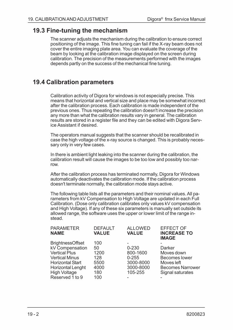
820082319 - 2
19. CALIBRATION AND ADJUSTMENT Digora® fmx Service Manual
19.3 Fine-tuning the mechanismThe scanner adjusts the mechanism during the calibration to ensure correctpositioning of the image. This fine tuning can fail if the X-ray beam does notcover the entire imaging plate area. You can evaluate the coverage of thebeam by looking at the calibration image displayed on the screen duringcalibration. The precision of the measurements performed with the imagesdepends partly on the success of the mechanical fine tuning.
19.4 Calibration parameters
Calibration activity of Digora for windows is not especially precise. Thismeans that horizontal and vertical size and place may be somewhat incorrectafter the calibration process. Each calibration is made independent of theprevious ones. Thus repeating the calibration doesn't increase the precisionany more than what the calibration results vary in general. The calibrationresults are stored in a register file and they can be edited with Digora Serv-ice Assistant if desired.
The operators manual suggests that the scanner should be recalibrated incase the high voltage of the x-ray source is changed. This is probably neces-sary only in very few cases.
In there is ambient light leaking into the scanner during the calibration, thecalibration result will cause the images to be too low and possibly too nar-row.
After the calibration process has terminated normally, Digora for Windowsautomatically deactivates the calibration mode. If the calibration processdoesn't terminate normally, the calibration mode stays active.
The following table lists all the parameters and their nominal values. All pa-rameters from kV Compensation to High Voltage are updated in each FullCalibration. (Dose only calibration calibrates only values kV compensationand High Voltage). If any of these six parameters is manually set outside itsallowed range, the software uses the upper or lower limit of the range in-stead.
PARAMETER DEFAULT ALLOWED EFFECT OFNAME VALUE VALUE INCREASE TO
IMAGEBrightnessOffset 100 - -kV Compensation 50 0-230 DarkerVertical Plus 1200 800-1600 Moves downVertical Minus 128 0-255 Becomes lowerHorizontal Start 5500 3000-8000 Moves leftHorizontal Lenght 4000 3000-8000 Becomes NarrowerHigh Voltage 180 105-255 Signal saturatesReserved 1 to 9 100 - -

19 - 38200823
Digora® fmx Service Manual 19. CALIBRATION AND ADJUSTMENT
19.5 Usable calibration ranges
The calibration range is from 0.01 to 1.0 seconds with most intraoral x-raysources. This means that x-ray doses from 0.01 to 1.0 seconds give validcalibration result with all the calibration parameters.
The usable x-ray dose range after calibration is from 10 % to 100 % com-pared to the calibration dose. If too low dose (less than 10 %) is used, theimage may be too light (nothing in the image is really black). If too high dose(above 100 %) is used, the darkest areas of the image may saturate (thereare no details left in them although they may be not quite black).
19.6 How the calibration range is achieved
Imaging plates have very wide dynamic range, as well as some x-ray gen-erators. The calibration is used to adapt the ten-fold range (10 to 100 %) ofthe scanner to the range of the imaging plates and x-ray generators.
The calibration routine of the scanner controls the sensitivity of the photodetector (photomultiplier tube) by adjusting its high voltage bias supply (HighVoltage). It is also controls the gain of the photomultiplier signal amplifierwhich adjusts the signal to fit into the dynamic range of the 8-bit A/D con-verter. The value of parameter kV Compensation is used as the referencevalue for the A/D conversion result.
The calibration routine replaces the normal preread routine carried outbefore the actual image readout. At the beginning of calibration the stepperstarts to advance the imaging plate, the high voltage is set to a middle val-ues (180 as the parameter), kV Compensation is set to nominal value (50 asthe parameter) and the gain is set to maximum (255 as the parameter). Thescanner starts to read the imaging plate and decreases the gain if the A/Dconversion result exceeds the reference value. If the gain becomes verysmall, the high voltage is decreased, the gain is set to maximum and theimaging plate is read again. This is repeated until the gain stays largeenough. If the gain becomes too large, the high voltage is increased, thegain is set to maximum and the imaging plate is read again.
After both the high voltage and gain have settled, the actual image readout isdone. During the readout, the scanner searches for the largest signal (dark-est pixel of the image). After the readout, the scanner calculates the differ-ence of the largest signal from a pre-set reference value and adjusts thekVCompensation parameter accordingly. The High Voltage andkVCompensation parameters are the updated with the new values.

820082319 - 4
19. CALIBRATION AND ADJUSTMENT Digora® fmx Service Manual
After calibration, the High Voltage and kVCompensation parameters areused as fixed values in normal preread routine before actual image readout.The High Voltage sets the sensitivity of the photomultiplier (and thus theoverall dynamic range) and kVConpensation is again used as a reference(setting the density of the image). Gain is initially set to maximum and de-creased during the preread if the A/D conversion result exceeds the refer-ence value. After the preread, the image readout is done with the gain fixedduring preread.
19.7 Control of the gray scale output of the scanner
The calibration dose sets the allowed x-ray dose range, as described ear-lier. The parameter kVCompensation sets the density of the images. Itssetting after the calibration is completed depends.
1 slightly of the high voltage of the x-ray generator used for the calibrationdose
2 of the properties of the preread lens inside the scanner and3 of the parameter Brightness Offset during calibration
You can control how the calibration sets the kVCompensation parameter byusing the Brightness Offset of next Readout setting just before you start thecalibration. Alternatively, you can edit the kVCompensation parameter di-rectly with Digora Service Assistant.
To temporarily change the gray scale output of the scanner, use the Bright-ness Offset of Next Readout before reading any normal image. It affects theimage data of a single image the scanner reads after you have set a non-zero percentage there. You can use either positive or negative percentage.The non-zero percentage is automatically reset after the next readout.

19 - 58200823
Digora® fmx Service Manual 19. CALIBRATION AND ADJUSTMENT
19.8 Control of the gray scale display of Digora forWindows
After the scanner has produced images, you can control the way Digora forWindows displays the gray scale. These controls don't affect the originalimage data but the way it is displayed.
The basic setting is straight-forward: if you remove the cross from the boxPerform Automatic Grayscale Adjustment (After Readout) in the submenuGeneral Setup under the Options menu, Digora for Windows will show allnew images without trying to optimize the grayscale display. This often givesan impression that the images have poor contrast.
If you do the opposite selection and put a cross to the box, the AutomaticGrayscale Adjustment suggests an optimized grayscale that it calculatesfrom the histogram of the image. The idea of Digora for windows is to ini-tially read the images with the scanner having a bit too wide grayscale ( tobe sure that the desired grayscale information is also included) and then usethe Automatic Grayscale Adjustment to display the desired information.The Automatic grayscale Adjustment obviously makes a lot of compromisesand presumptions which can't suit all images. If the result of the AutomaticGrayscale Adjustment tends to be usually too dark or too bright, use theBrightness Correction of the Automatic Grayscale Adjustment of the Auto-matic Grayscale Adjustment Setup submenu of the Options menu to controlAdjustment. You can use either a positive or negative percentage.
The same setup percentage works both for the Automatic Grayscale Adjust-ment you can activate from the Readout Setup and for the AutomaticGrayscale Adjustment you activate from the button in the Tools window.

820082319 - 6
19. CALIBRATION AND ADJUSTMENT Digora® fmx Service Manual

20 - 18200823
Digora® fmx Service Manual20. TROUBLESHOOTING
20. Troubleshooting
PROBLEM #1.THE POWER INDICATOR IS NOT ON CAUSE:1. The power lead is loose.2. There is no mains power supply.3. The fuse is blown.4. There is a hardware failure.
CORRECTIVE ACTION:1. Connect the power cord correctly.2. Connect the mains plug to a live power supply.3. Replace the fuse at the rear of the unit.4. Remove the covers, check the internal cables.
Note that some pcb:s have LED`s for supply voltage indication.
PROBLEM #2.THE MAGNET DOES NOT ENGAGE THE IMAGING PLATE
CAUSE:1. The previous imaging plate is still in the scanner.2. The wrong image size was selected.3. The end of the bag is folded or incompletely cut.
CORRECTIVE ACTION:1. Remove the previous plate.2. Select the correct image size.3. Push the imaging plate gently out of the bag.

820082320 - 2
20. TROUBLESHOOTING Digora® fmx Service Manual
PROBLEM #3.THE READOUT PROCESS DOES NOT START
CAUSE:1. Digora has not been switched on.2. The interface cable between the scanner and the computer is loose.3. The scanner mechanism has not warmed up yet.4. The previous imaging plate is still in the scanner.5. The imaging plate has been placed in the scanner the wrong way round.6. There is a hardware problem with Digora.
CORRECTIVE ACTION:1. Switch on Digora, if the power indicator light is off.2. Connect the cable correctly.3. Wait until the scanner mechanism has warmed up.4. Remove the previous imaging plate.5. Reposition the imaging plate quickly and press the Action buttons to
close the scanner door.6. Check the reflective sensor, refer Chapter 8.
PROBLEM #4.THE DENTAL IMAGE DISPLAYED ONTHE SCREEN IS COMPLETELY WHITE
CAUSE:1. The imaging plate has not been exposed or it
was incorrectly positioned in the patient´s mouth.2. The X-ray device is faulty or the Digora scanner
is faulty.
CORRECTIVE ACTION:1. Exposure a new image.2. Check the operation of the scanner as follows:2.1 Start image scanning normally2.2 Open the scanner door in the middle of the scanning sequence.2.3 Look inside the door. If you see scattered red light, the laser inside the
scanner is working.2.4 When you open the scanner door in the middle of scanning sequence,
the image displayed on the screen should change from white to gray orblack. The image may also have slanted stripes.
2.5 If you saw a red light and if the white image became darker, the scanneris working and the X-ray device is faulty.

20 - 38200823
Digora® fmx Service Manual20. TROUBLESHOOTING
PROBLEM #5.IF THE DENTAL IMAGE DISPLAYED ON THESCREEN...
1. has black stripes on it or is completely black.2. contains a ghost image.3. contains traces of bubbles or stains.4. contains a white frame.
CAUSE:1.1 The scanner door was not closed properly.2.1 The imaging plate has been stored too long in a protective bag.2.2 The erasing lamp inside the scanner is defective.2.3 The imaging plate is dirty.2.4 The imaging plate is scratched.3.1 The protective bag has leaked.3.2 The imaging plate has been damaged by improper cleaning solvent.4. The calibration of the scanner has failed or the image position settings
of the scanner have changed or the image plate has been insertedincorretly.
CORRECTIVE ACTION:1.1 Check whether the door will close properly. If not, contact the service
representative.2.1 Expose a new image.
NOTE: Imaging plates sealed in protective bags should not bestored for more than three days.
2.2 Contact the service representative.2.3 Wipe the imaging plate gently with a swab
moistened with alcohol.2.4 Discard the imaging plate.3.1 Discard the imaging plate.
NOTE: Always seal protective bags carefully.
3.2 Discard the imaging plate.4. Re-calibrate Digora, if reoccurs.

820082320 - 4
20. TROUBLESHOOTING Digora® fmx Service Manual
PROBLEM #6.THE IMAGE APPEARS TO SHOW THE OPPOSITE JAW; I.E. THEIMAGE IS MIRRORED.
CAUSE:The imaging plate has accidentally been inserted back to front in the pa-tients mouth, thereby creating a mirror image. The imaging, plate in theprotective bag, may also have been placed back to front. This mistake couldhave led you to insert the imaging plate the wrong way around in the scanner.
CORRECTIVE ACTION:Select the Mirror command in the Image menu and reply Yes in the confirma-tion question. As the image was taken on the wrong side of the imagingplate, the image is noisier than normally.

20 - 58200823
Digora® fmx Service Manual20. TROUBLESHOOTING
THE FOLLOWING WITH THE AUTOLOADER:
PROBLEM #1.THE IMAGING PLATE READ OUT DOES NOT START WHEN ACTIONBUTTON IS PRESSED.
1. The unit only gives beeper sound.2. Imaging plates are moved from the magazine and they drop to the
imaging plate tray and a beeping sound is heard. No scanned imagesappear.
3. Autoloader moves imaging plate from the cassette but does not start toread it.
CAUSE:1.1 Autoloader motor is disconnected or broken.1.2 Image plate is jammed in the track.2.0 Autoloader position detector is disconnected or needs adjustment.3.0 One of the imaging plates was inserted back side pointing to the plate
feeding mechanism.
CORRECTIVE ACTION:1.1 Reconnect or replace the motor.1.2 Remove the jammed imaging plate. Find out the reason for the jam andinform the operators for correct usage of the unit.
NOTE:The imaging plate frames must be properly fitted on the plate in order not tomake autoloader get jammed.
2.0 Verify the correct operation of Autoloader microswitch.3.0 Press the Action button to bring the image plate out. Remove it quicklyfrom the imaging plate tray, put the tray in place and insert the imagingplate back to the cassette in the correct way and close the door.

820082320 - 6
20. TROUBLESHOOTING Digora® fmx Service Manual
PROBLEM # 2.DEFECTIVE AUTOLOADER
At power on beeper sound is generated.
CAUSE:Autoloader motor is not running or position detector is not working.
CORRECTIVE ACTION:Reconnect or replace the motor or microswitch.
PROBLEM # 3.AUTOLOADER PROBLEM
CAUSE:
The imaging Plate readout starts when action button is pressed with andwithout imaging plate.
CORRECTIVE ACTION:Check the reflective sensor. Refer Chapter 8.

21 - 18200823
Digora® fmx Service Manual 21. LIST OF ACCESSORIES/REC. SPARE PARTS
21. LIST OF ACCESSORIES/RECOMMENDED SPAREPARTS
This chapter lists the accessories and technical literature that can be usedwith Digora fmx
21.1 Accessories:CODE DESCRIPTION3900130 Main cord, European style3900215 Main cord, USA style
4801045 Interface cable 1,5 m4801046 Interface cable 10 m4801262 Foot Pedal (DfW 2.0 Video Capture)
4801099 P4601 - Interface adapter board, ISA bus4801273 P4602 - Interface adapter board, PCI bus1200180 SVRAM - 4 Mb
8200707 User Manual / English8200708 User Manual / Finnish8200709 User Manual / French8200805 User Manual / German8200806 User Manual / Italian8200807 User Manual / Spanish8200823 Service Manual /English
8200846 Spare Part Cataloque / English8200847 Accessory Catalogue / English9801307 HR Imaging plates (8pcs standard, 2 pcs small) in storage
box9801308 HR Imaging plates (10pcs standard) in storage box9801309 HR Imaging plates (10 pcs small) in storage box
9801385 SR Imaging plates (8pcs standard, 2 pcs small) in storagebox9801386 SR Imaging plates (10pcs standard) in storage box

820082321 - 2
21. LIST OF ACCESSORIES/REC. SPARE PARTS Digora® fmx Service Manual
9801387 SR Imaging plates (10 pcs small) in storage box
9801765 HR Imaging plates (8pcs standard, 2 pcs small) - Japan9801887 HR Imaging plates (10pcs standard) in storage box - Japan9801888 HR Imaging plates (10 pcs small) in storage box - Japan
9801954 SR Imaging plates (8pcs standard, 2 pcs small) - Japan9801955 SR Imaging plates (10pcs standard) in storage box - Japan9801956 SR Imaging plates (10 pcs small) in storage box - Japan
9801871 Disposable plastic bags for standard Imaging plates(500 pcs roll)
9801872 Disposable plastic bags for small Imaging plates(500 pcs roll)
9801926 Disposable plastic bags for standard Imaging plates(20 x 500 pcs roll)
9801927 Disposable plastic bags for small Imaging plates(20 x 500 pcs roll)
9890123 Imaging Plate Holder - Super-Bite9890124 Imaging Plate Holder - Kwick-Bite/Bite Wing
9891865 Autoloader for FMX systems

21 - 38200823
Digora® fmx Service Manual 21. LIST OF ACCESSORIES/REC. SPARE PARTS
21.2 Recommended spare parts for Digora fmx:
CODE DESCRIPTION
1250034 P4100 Eprom1250087 P4000-2 Software 3.00 for ISA bus1250099 P4000-2 Software 3.10 for PCI bus
2800054 T4400 Power Supply4801094 P4000-2 Processor Board
3600035 Mains fuses 1,6 AT (10 pcs)3600056 Mains fuses 1.6 AT (10 pcs) 5 x 203200151 Erasing Lamp3200150 Mains Switch3900215 Power Cord
4801042 T4100-1 Protect / Service Switch
4801270 T4501 Key and Display4801271 T4101 Stepper Drive and Hv-Supply
4801099 Interface Board, ISA bus4801306 Interface Board, PCI bus
4801037 P4000-1 Transp.Opto4801038 Reflective Sensor4801040 Microswitch assy, autoloader
4801045 Interface cable 1,5 m4801046 Interface cable 10 m
4801234 Pre-read lens motor4801246 Autoloader motor
6101190 Screw Shaft6102530 Upper Guide Bar6309260 Lower Guide Bar6803100 Slide (for transport trolley)6902730 Laser Diode Module
9801312 Cover Assembly9801421 Galvanometer9801897 Front panel assy, autoloader9801898 Front panel assy, middle9801899 Front panel assy, right9801900 Front panel assy, left
9891421 Galvanometer mirror assembly9891785 Pre read assembly9891281 Plastic Tonque + with magnet

820082321 - 4
21. LIST OF ACCESSORIES/REC. SPARE PARTS Digora® fmx Service Manual

22 - 18200823
Digora® fmx Service Manual 22. LIST OF TOOLS REQUIRED
22. LIST OF TOOLS REQUIRED
All tools are metric.
22.1 Allen keys:— 4 mm— 3 mm— 2.5 mm— 2 mm
22.2 Closed loop wrenches:— 8 mm— 7 mm— 5.5 mm
22.3 Screwdrivers:— Pozidriv 1— Slotted screw ( in screw terminals)
22.4 Torque spanners for torques of— 0,4 Nm with allen key 4 (Clamp for Lens and laser Assemblies).— 0,7 Nm with hex socket 8 (Clamp for Light Guiding Tube).— 3 Nm with Allen key 4 (Steel Tube containing Photomultiplier Tube).
22.5 Miscellaneous— Screw M4x20
(To pull out the bearing holder when dismantling the screw shaft.)— Protective glasses (for laser light).

820082322 - 2
22. LIST OF TOOLS REQUIRED Digora® fmx Service Manual

23 - 18200823
Digora® fmx Service Manual23. MAINTENANCE SCHEDULE
23. MAINTENANCE SCHEDULE
Following maintenance program should be carried out annually / biannually,depending on the usage of the scanner.
1. Remove scanner top cover
2. Clean and lubricate transport unit drive shaft and guiding rods.• refer to chapter 5 in service manual
3. Clean optical system (lenses and mirrors) from dust, usingcompressed air.• refer to chapter 8 in service manual
4. Proper operation of safety/service switch.• refer to chapter 2 in service manual, for precautions, when performing
this test• make sure that switch is in up position• start read out by inserting an imaging plate and pressing the action
button• scanning sequence should be completed without activation of the
laser beam and photomultiplier high voltage• verify proper operation of the erasing lamp at end of the sequence
5. Replace all covers.
6. Resolution and linearity test.• take a test image from resolution phantom• place phantom so that lines are parallel to long side of the plate and
numbers indicating resolution are visible on right side of the image• use density measurement tool of Digora for Windows to evaluate
resolution• image should produce 8 LP/mm• verify that numbers, indicating resolution, are equal in height
7. Image quality test• expose imaging plate (without object) and scan it• verify that there are no stripes, caused by transport unit or ambient
light leaking in the scanner• for corrective action, refer to chapter 5 in service manual
8. Condition of the imaging plates• imaging plates with scratches or having frames which are not fitting
properly are recommended not to be used

820082323 - 2
23. MAINTENANCE SCHEDULE Digora® fmx Service Manual

24 - 18200823
Digora® fmx Service Manual 24. AUTOLOADER
24. AUTOLOADER24.1 Autoloader
The Digora fmx can be equipped with a optional Autoloader for readingseveral imaging plates from the magazine one after each other. Maximumcapacity of the magazine is 20 imaging plates.
Autoloader comprises:a) a magazineb) a pair of timing beltsc) a DC motord) a microswitch.
FIGURE 24 - 1: Autoloader comprises

820082324 - 2
24. AUTOLOADER Digora® fmx Service Manual
FIGURE 24 - 2: Parts of the Autoloader unit1) Main switch2) Control Panel3) Image size selector4) Small size Indicator light5) Normal size Indicator light6) Scan button7) Scan Indicator light8) Power ON Indicator light9) (not in autoloader unit)10) Imaging plates in the Imaging Plate magazine11) Autoloader door12) Autoloader Imaging Plate Tray
The imaging plates are loaded in the magazine between the moving cylinderand the timing belt or the last loaded imaging plate. The cylinder pushes theimaging plates towards the timing belt and keeps the imaging platesstraight. There are also magnets in the autoloader frame that pull theimaging plates towards the timing belt.The timing belt back has also teeth. The distance between two consecutiveteeth allows the imaging plate to fit between them. The timing belt movesthe imaging plates vertically. The first position of imaging plate is the maga-zine, the second position is 4.1 cm lower than the first inside the track coverand third is another 4.1 cm lower where the image plate holder will engagethe imaging plate.
The DC-motor drives the timing belt and when the microswitch switches themicroprocessor stops the motor. These steps are equivalent to a 4.1 cmmovement of the timing belt which represents a movement of one imagingplate from one position to the next.

24 - 38200823
Digora® fmx Service Manual 24. AUTOLOADER
24.2 Installation of the Autoloader1. Remove the middle cover from DIGORA fmx unit. It is held in place by
magnets.
2. Remove the door by removing the two M4 screws. Keep the screwsbecause they will be needed when the similar Autoloader door isinstalled.
3. Remove the two screws at the left side of door assembly. Keep thescrews because they will be needed when the Autoloader is installed.
4. Remove the two screws holding the left front cover (with thekeyboard) and grip the front cover from the left hand side of itand push it to the left to release the two hidden supports holdingthe front panel in place.
FIGURE 24 - 3
5. Remove the Autoloader rear cover by removing M4 allen screw.
6. Remove the Autoloader front cover by removing the three Allen screws
FIGURE: 24 - 4 FIGURE 24 - 5

820082324 - 4
24. AUTOLOADER Digora® fmx Service Manual
7. Place the Autoloader to the front plate and install it using the screws (3).8. Connect the Autoloader microswitch 2 pin connector (J4504) and the
motor 4 pin connector (J4503) to the T4501 (Key&Display board). Placea jumper on the 2-pin connector JP2 (Mode) of the T4501 board. Thistells the microprocessor that the Autoloader is in use.
9. Replace the left front cover and tighten the screws. Make sure that whilepushing the cover in place the Autoloader connectors do not becomeloose from T4501.
FIGURE 24 - 6
10. Switch ON the Digora and switch it OFF when the imaging plateholder has come completely out. Put the adjusting plate betweenimaging plate holder and the autoloader frame (Note that there shall beno timing belt tooth prohibiting to do this). Adjust the Autoloader positionby loosening its fixing screws, moving it to be in touch with the imagingplate holder adjustment plate being in place. Tighten the fixing screws.Remove the adjustment plate.

24 - 58200823
Digora® fmx Service Manual 24. AUTOLOADER
FIGURE 24 - 7
11.Assemble the new door assembly so that when the door closes it willstop on the autoloader frame, not on the front plate. Note also that theleft side of it verticallly lines up with the autoloader frame thus preventingambient light to get in the unit. This can be best seen when erasing lampis on (by scanning an imaging plate or by using DSA).
FIGURE 24 - 8
12.Switch ON the unit , put some imaging plates in the magazine. Checkthat the cylinder pushes the imaging plates towards the timing belt andkeeps the imaging plates straight. If you can see the teeth of timing beltwithinthe magazine, it means that the start position must be adjusted.See instructions ”Adjustment of the micro switch”. Press the Action buttonand verify the correct operation of the Autoloader. Verify that the dooropens and closes properly without getting stuck. Readjust if necessary.
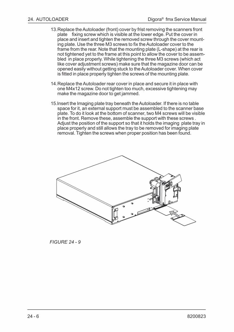
820082324 - 6
24. AUTOLOADER Digora® fmx Service Manual
13.Replace the Autoloader (front) cover by frist removing the scanners frontplate fixing screw which is visible at the lower edge. Put the cover inplace and insert and tighten the removed screw through the cover mount-ing plate. Use the three M3 screws to fix the Autoloader cover to theframe from the rear. Note that the mounting plate (L-shape) at the rear isnot tightened yet to the frame at this point to allow the cover to be assem-bled in place properly. While tightening the three M3 screws (which actlike cover adjustment screws) make sure that the magazine door can beopened easily without getting stuck to the Autoloader cover. When coveris fitted in place properly tighten the screws of the mounting plate.
14.Replace the Autoloader rear cover in place and secure it in place withone M4x12 screw. Do not tighten too much, excessive tightening maymake the magazine door to get jammed.
15.Insert the Imaging plate tray beneath the Autoloader. If there is no tablespace for it, an external support must be assembled to the scanner baseplate. To do it look at the bottom of scanner, two M4 screws will be visiblein the front. Remove these, assemble the support with these screws .Adjust the position of the support so that it holds the imaging plate tray inplace properly and still allows the tray to be removed for imaging plateremoval. Tighten the screws when proper position has been found.
FIGURE 24 - 9
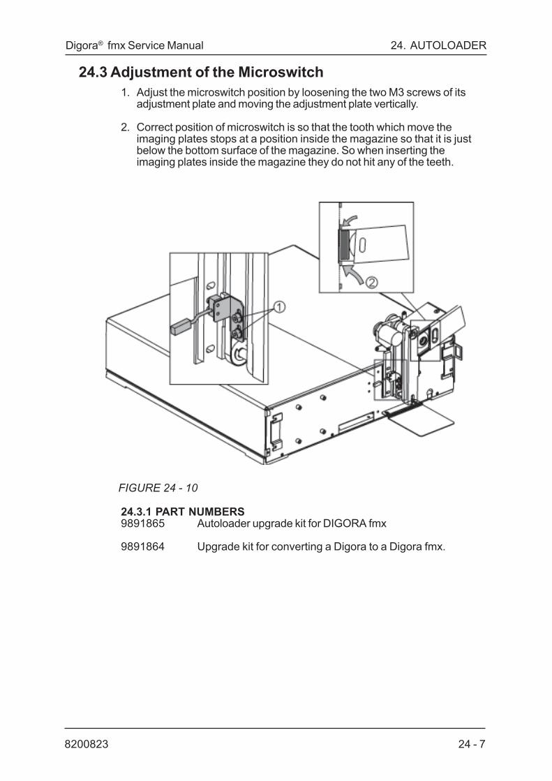
24 - 78200823
Digora® fmx Service Manual 24. AUTOLOADER
24.3 Adjustment of the Microswitch1. Adjust the microswitch position by loosening the two M3 screws of its
adjustment plate and moving the adjustment plate vertically.
2. Correct position of microswitch is so that the tooth which move theimaging plates stops at a position inside the magazine so that it is justbelow the bottom surface of the magazine. So when inserting theimaging plates inside the magazine they do not hit any of the teeth.
FIGURE 24 - 10
24.3.1 PART NUMBERS9891865 Autoloader upgrade kit for DIGORA fmx
9891864 Upgrade kit for converting a Digora to a Digora fmx.

820082324 - 8
24. AUTOLOADER Digora® fmx Service Manual

Digora® fmx Service Manual 25. TECHNICAL SPECIFICATIONS
8200823 25 - 1
25. SPECIFICATIONS AND SYSTEM REQUIREMENTSImaging plates
Imaging Plates: Normal Size (2) Small Size (0)
Dimensions: 35 x 45 x 1,6 mm 26 x 35 x 1,6 mmImage Area: 30 x 40 mm 21 x 30 mmImage Size: 466 x 628 pixels 326 x 466 pixels
Pixel Size: - 64 x 64 micrometers
Resolution: - More than 8 line pairs per millimeter.
Image File: - 286 KB or 75 KB (lossy compression).Recommended
dose: - 20 ... 50 % of a typical X-ray film exposure dose.
Storage: - Imaging plates must be stored in their box below33ºC.- The box must be closed to remain dust free.
Cleaning: - Use lint free cotton or lens cleaner to wipe imagingplates.- Use ethanol anhydride dampened cleaning clothsto clean stains that do not come off easily.- Never use any other cleaning solvents.
Disposal: - Imaging plates are problem waste. They must bereturned to the manufacturer for disposal.- Never use damaged imaging plates.
Material - Europium activated Barium fluorohalide.

25- 2 8200823
25. TECHNICAL SPECIFICATIONS Digora® fmx Service Manual
UnitDXR 40 Classification IEC601-1
- Class I equipment.- Type B equipment.- Continuous operation.- IPX0 (enclosed equipment without protection againstingress of liquids).
Operating voltage: - 100 - 240 V, 50 - 60 Hz.
Current: - Less than 1,3 A.
Operating environment:- +10 -+ 40ºC, 30 - 75 RH%, 800 - 1080 mbar- Dental office or other dry and dustless space.- When not in use keep the scanner door closed.
Operation postition:- Horizontal, can be placed under the PC and display.
Storage/Transportation:- +0 - +50ºC, 0 - 85 RH%, 500 - 1080 mbar.
Cleaning: - Equipment can be cleaned with water or ethanolor a mixture of both.
Maintenance: - Maintenance must be performed annually by aservice representative authorized by the manufacturer.
SCANNER DIMENSIONS: Width: 450mm/17.7"Depth: 445mm/17.5"Height: 130mm/5.1"Weight: 20kg/44lbs
Interface cables:- 1,5m/59" (code:4801045) and 10m/394" (code: 4801046)
Disposal:At the end of the useful working life of the equipmentand/or its accessories make sure that you follow nationaland local regulations regarding the disposal of theequipment, its accessories, parts and materials.The equipment includes some or all of the following partsthat are made of or include materials that are non-envi-ronmentally friendly or hazardous:- batteries- x-ray tube head (Pb, Be and mineral oil)- all electronic circuit boards- z-carriage counter weight (Pb)- cassettes (Pb), intensifying screens and imagingplates
Digora® fmx Service Manual 25. TECHNICAL SPECIFICATIONS
8200823 25 - 3
Hardware requirements
* Operating System: WIN 95/98 or Windows NT
* PC: Pentium Processor or better,3.5" 1.44Mb Disk drive,CD-ROM, CD-R drive recommended
RAM-Memory 64 Mb or moreHard Disk More than 2 GbMonitor Min. 15" SGVA, (17" recommended),
1024 x 768 pixels True Colour over 70 Hz
Display Adapter 64-bit accelerated with 8 Mb or betterBack-up (SCSI) Tape drive or other back-up
device supported by Windows
Connection to the PC must meet IEC 601-1 requirements.
* The use of ACCESSORY equipment not complying with theequivalent safety requirements of this equipment may lead to areduced level of safety of the resulting system.
Consideration relating to the choice shall include:- use of the accessory in the PATIENT VICINITY- evidence that the safety certification of the ACCESSORY has beenperformed in accordance to the appropriate IEC 601-1 and/orIEC 601-1-1 harmonized national standard- only RS 232C interface cable, provided by the manufacturer, shall be used.PROTECTIVE BAGS:
* Disposable protective bags for both imaging plate sizes in rolls enclosedin box.Material: - PolyetheneDisposal: - Follow the national requirements. Can be burned if
allowed.

Digora® fmx Service Manual 26. CONVERTING TO FMX
8200823 26 - 1
26. CONVERTING A DIGORA TO A DIGORA FMXThese instructions describe how to upgrade a DIGORA (type number DXRXXX-02, X=any number) to a DIGORA fmx unit. The upgraded unit will onlybe equivalent to DIGORA fmx with the latest version of Interface boardP4601- 1 and Digora for Windows 2.0 software installed.
Upgrade kit includes the following parts;· front panel assembly (including new erasing lamp, Key & Display T4501
board)· three plastic front covers· mains switch· adapter flat cable 40/20 pin· tape seal protective bags (2x500 pcs)· type SR imaging plates (8+2 IP’s)· 8lp/mm EPROM 3.0 software for the P4000 processor board· DIGORA fmx Scanner driver version 2.20. This software is needed
ONLY if the latest Digora for Windows 2.0 is already installed· DIGORA fmx user’s and Installation manual· Upgrade instructions
NOTE!!!!The latest version of Digora for Windows 2.0 software and P4601-1Interface board upgrade are not included in the above fmx update kit.These items has to be ordered separately.
Note also that the PC hardware requirements are different comparedto the older versions of Digora for Windows.

26 - 2 8200823
26. CONVERTING TO FMX Digora® fmx Service Manual
INSTRUCTIONSDisconnect the unit from mains before performing the update to the unit
1. Remove the front panels, the top cover, the front cover (including theseaming and cutting unit).
When removing the covers from the Digora scanner, first remove thecover of the cutting unit that is held in place with magnets. Remove thecover by pulling it way from the scanner.
1) Open the two M3 Allen screws now revealed in the right hand side ofthe scanner front panel.

Digora® fmx Service Manual 26. CONVERTING TO FMX
8200823 26 - 3
2) Grip the front panel from the left hand side of it and push it to the left torelease the two hidden supports holding the front panel in place.
3) Lay the front panel flat in front of the scanner.
4) Open the M3 allen screw in the left hand side of the revealed scannerfront panel. Disconnect hot seaming unit cables and flat cable fromT4500 board (Key&Display).

26 - 4 8200823
26. CONVERTING TO FMX Digora® fmx Service Manual
5) Then open the two M4 allen screws at rear, holding the cover in place.
6) Now you can lift off the scanner cover by pushing it slightly inwardsfrom the sides.
7) Since the cover is fitting tightly in the longitual grooves at the sides ofthe scanner base plate, it may be somewhat tight. Don't let the cover tiltwhen lifting it up avoid it getting stuck in vertical direction. When youlift the cover off, a flap inside the cover toggles the safety/service switchthat disables the laser tube and the power supply of the photomultipliertube.
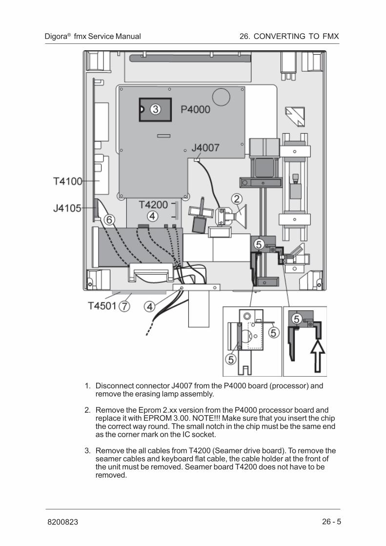
Digora® fmx Service Manual 26. CONVERTING TO FMX
8200823 26 - 5
1. Disconnect connector J4007 from the P4000 board (processor) andremove the erasing lamp assembly.
2. Remove the Eprom 2.xx version from the P4000 processor board andreplace it with EPROM 3.00. NOTE!!! Make sure that you insert the chipthe correct way round. The small notch in the chip must be the same endas the corner mark on the IC socket.
3. Remove the all cables from T4200 (Seamer drive board). To remove theseamer cables and keyboard flat cable, the cable holder at the front ofthe unit must be removed. Seamer board T4200 does not have to beremoved.

26 - 6 8200823
26. CONVERTING TO FMX Digora® fmx Service Manual
4. Remove the interrupter plate (interrupts the opto switch) and the imagingplate holder from the transport mechanism. Install the new imaging plateholder and the new interrupter plate using the original screws.
NOTE: Digora units with serial number smaller than G61308 have a lift mo-tor to lift the imaging plate to a certain height. The motor is attached to aaluminium ring outside the light guiding tube. This ring (and the lift motor)must be removed . Remove the ring completely by first moving the transportmechanics fully in so that it will be out of way and then loosening the allen setscrews of the ring and pulling it out.
5. Take the new adapter flat cable 40/20 pin and connect the 40 pinconnector at one end of the flat cable to the connector J4105 on theT4100 board. The flat cable must be routed under the photo multipliertube and the cable holder. Tighten the cable holder in place.
6. Install new front panel assembly using the original screws. Connect theflat cable connector 20pin to the T4501 board.
7. Connect the new main switch(ON/OFF) cable in place so that firstremove the two flat connectors from the mains filter (not the yellow/ greenlead). Connect the two female flat connectors of the mains switch cableto the mains filter (polarization does not matter).
Connect then the male flat connectors of the cable to the femaleconnectors that were removed from the mains filter. Pull the tubing onthis connection and by using heat make the tubing to shrink (to keep inplace). NOTE!! The old main switch must be ON all the time otherwisethe new main switch does not work.

Digora® fmx Service Manual 26. CONVERTING TO FMX
8200823 26 - 7
8. Drill a new hole (diameter 4mm) in the edge of the top cover accordingto the drilling drawing. A drilling guide is supplied with the kit to assist todrill the new hole.
9. Replace the top cover. When you close the covers, make sure they don'tdisengage the cables of the photomultiplier tube.
10.Connect the keyboard flat cable connector, attached to the left handcover, to the T4501 key & display board.
NOTE!!! The correct orientation of the cable connected to theboard is such that the black edge of it is pointing down.
11.Install the both plastic covers (left and right hand side) using M4 allenscrews.
12.Install the middle plastic cover. It is held in place with magnets.

26 - 8 8200823
26. CONVERTING TO FMX Digora® fmx Service Manual
INTERFACE BOARDThe interface board in the computer must be version P4601-1 which in-cludes the 4Mb SRAM memory chip for the image memory.
NOTE!!!Before upgrading check the serial number of the Scanner to seewhat version of Interface board has been installed in the PC andcheck from the table below what changes might have to be made tothe interface board.
Old board P4600 must be replaced with new board P4601-1 on which isinstalled the new 4Mb SRAM.
Board P4601 need not be replaced BUT the new 4Mb SRAM memory chipMUST be installed in socket IC6. If there are any 1Mb SRAMs in the slotsIC5 and IC6 they MUST be removed.
Scanner serial numbers and interface board versions
Scanner PC interface SRAMs boardDigora before G50730 P4600 No SRAM socketsDigora from G50730 P4601 Empty socketDigora from G62068 P4601 2 x 1Mb SRAM (IC5, IC6)Digora fmx from G94473 P4601-1 1 x 4Mb SRAM (IC6)
Upgrading Interface board version P4600 to version P4601
1. Remove the cover from the PC
2. Remove the old P4600 Interface board.
3. Check that the base address of the new Interface board is the same asthe old one (location of the address jumpers).
4. Install the new P4601 Interface board and secure in to place with screw.
5. Replace the PC cover.

Digora® fmx Service Manual 26. CONVERTING TO FMX
8200823 26 - 9
Upgrading Interface board version P46011. Remove the cover from the PC2. Remove the P4601 interface board3. If IC sockets IC5 and IC6 are empty install SRAM circuit to the socket
IC6, see the drawing below.
NOTE!!! Make sure that you insert the chip the correct way round. Thesmall notch in the chip must be the same end as the corner mark onthe IC socket.
4. If there are already SRAM circuits installed, remove both and install thesingle latest version. The old type of SRAM does not have enoughmemory (old type 1Mb each, new type 4Mb).
5. Check that the base address of the new interface board is the same asthe old one (location of the address jumpers).
6. Reinstall the upgraded interface board and secure in to place with screw.Reinstall the PC cover and secure in with screws.

26 - 10 8200823
26. CONVERTING TO FMX Digora® fmx Service Manual
SCANNER DRIVER 2.20
DIGORA fmx unitsThe Scanner driver upgrade is needed ONLY if the latest Digora for Win-dows 2.0 is already installed.Before beginning please make sure that DfW 2.0 is installed in the compu-ter. The application, however, must not be running during this procedure.
1) Use the Explorer to study the disk labeled 'fmx scanner driver'.
2) Locate and launch 'fmxsetup.exe'. The following dialog will be displayed:
3) Use the Explorer to locate ('Browse') the current DSD.OCX in the systemto be updated. Following that, choose the desired user interfacelanguage and start the actual update by clicking the 'Update DSD' button.

Digora® fmx Service Manual 26. CONVERTING TO FMX
8200823 26 - 11
CALIBRATING THE SCANNERThe scanner must be calibrated after the upgrading. To calibrate the scan-ner, follow the instructions in the DIGORA fmx user’s and installation manualchapter 6.5.
PART NUMBERS9891864 Upgrade kit for converting a DIGORA to a DIGORA fmx
4801099 P4601-1 Interface board
1200180 4 Mb SRAM memory chip

26 - 12 8200823
26. CONVERTING TO FMX Digora® fmx Service Manual