dimensioning a multiple view drawing - world class cadworldclasscad.com/vba_pdf/ch 9 dimensioning a...
TRANSCRIPT

9-1
C h a p t e r 9
Dimensioning a Multiple View Drawing
In this chapter, you will learn how to use the following VBA functions to World Class standards:
! Beginning a New Visual Basic Application ! Opening the Visual Basic Editor in AutoCAD ! Laying Out a User Input Form in Visual Basic ! Creating and Inserting an Image into a Form in Visual Basic ! Insert a Label into a Form ! Insert a Textbox into a Form ! Insert Command Buttons into a Form ! Adding a Copyright Statement to a Form ! Adding Comments in Visual Basic to Communicate the Copyright ! Declaring Variables in a Program with the Dimension Statement ! Setting Variables in a Program ! Assigning Values to the Variables ! Inputting the Code to Set a System Variable ! Load AutoCAD Linetypes ! Inputting the Code to Create and Set Layers ! Inputting the Code to Draw in Visual Basic ! Using Selection Sets and Mirroring in Visual Basic ! Drawing a Centerline and Arraying the Line ! Drawing a Circle in VBA ! Dimensioning in VBA ! Resetting the Data with the cmdClear Command Button ! Exiting the Program with the cmdExit Command Button ! Executing a Subroutine with the cmdDraw Command Button ! Executing a Subroutine with the cmdPickPoint Command Button ! Inserting a Module into a Visual Basic Application ! Running the Program

9-2
Beginning a New Visual Basic Application _________________________________________________________ In this chapter, we will continue to learn how to use the Visual Basic Application (VBA) program to create a form and then to generate a drawing with dimensions automatically. We reiterate many elements of the earlier lessons, but now we add the capability to add multiple views, placing entities on specific layers, using selection sets, then mirroring and arraying entities in AutoCAD Model Space. In this chapter, we will place three dimensions on the finished orthographic views. Eventually in following chapters, we add text and drawing borders. At the beginning of every chapter, we will start a new Visual Basic Application project, use a sketch to determine the extent of what the program will do, create the form and then write the code. Once the code is finished, we will run the program and multiple orthographic views will appear on the graphical display with dimensions.
Figure 9.1 � Rough Sketch of the Standoff Form Remember, that all programming projects begin with one or more sketches, with one portraying the part, detail, or assembly and the other being the user input form. In this Visual Basic Project, the Standoff program, we will be running a user input form inside the AutoCAD application, so we need to sketch the structure of this special dialogue box. We will name the Input form, Standoff Program. We will place six textboxes on the left side of the form to key in the starting point of the Standoff, the across flats (AF) dimension, the inside diameter measurement and Standoff length. On the right side of the form, we will place an image of the Standoff. We will have four command buttons, Draw, Clear, Exit and Pick Point. On the bottom of the form, we will write the copyright statement using another label. On this

9-3
presentation, we can help ourselves by being as accurate as possible, by displaying sizes, fonts, colors and any other specific details which will enable us to quickly create the form. From the beginning of inserting the form into the project, we need to refer to our sketch. The sketch of the form is shown in Figure 9.1. Remember, we should train new programmers initially in the art of form building. When using the editor, we insert and size the form, and selecting the Controls Toolbox, we will place all the various input tools and properly label them. Whenever we place an input tool, the properties window will display a list of attributes associated with the tool, and we will take every effort to arrange the tool by performing such actions as naming, labeling and sizing the visual input device.
Opening the Visual Basic Editor in AutoCAD _________________________________________________________ Opening the Visual Basic Editor in AutoCAD is essential to creating the program to automate the drawing process. In this version of the World Class CAD � Visual Basic Applications for AutoCAD, we are using AutoCAD 2008, but we just finished using all the programs in this text with a group programming in AutoCAD 2000. Their drawings were automatically made just as efficiently as if they were using the most recent version of the Autodesk software.
Figure 9.2 � Launching the Visual Basic Editor
9-4
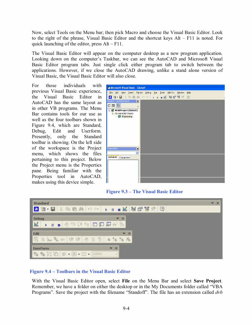
Now, select Tools on the Menu bar; then pick Macro and choose the Visual Basic Editor. Look to the right of the phrase, Visual Basic Editor and the shortcut keys Alt � F11 is noted. For quick launching of the editor, press Alt � F11. The Visual Basic Editor will appear on the computer desktop as a new program application. Looking down on the computer�s Taskbar, we can see the AutoCAD and Microsoft Visual Basic Editor program tabs. Just single click either program tab to switch between the applications. However, if we close the AutoCAD drawing, unlike a stand alone version of Visual Basic, the Visual Basic Editor will also close. For those individuals with previous Visual Basic experience, the Visual Basic Editor in AutoCAD has the same layout as in other VB programs. The Menu Bar contains tools for our use as well as the four toolbars shown in Figure 9.4, which are Standard, Debug, Edit and Userform. Presently, only the Standard toolbar is showing. On the left side of the workspace is the Project menu, which shows the files pertaining to this project. Below the Project menu is the Properties pane. Being familiar with the Properties tool in AutoCAD, makes using this device simple. Figure 9.3 � The Visual Basic Editor
Figure 9.4 � Toolbars in the Visual Basic Editor
With the Visual Basic Editor open, select File on the Menu Bar and select Save Project. Remember, we have a folder on either the desktop or in the My Documents folder called �VBA Programs�. Save the project with the filename �Standoff�. The file has an extension called dvb

9-5
which means DCL and Visual Basic programs as shown in Figure 9.5.
Figure 9.5 � Saving the Standoff Program
Laying Out a User Input Form in Visual Basic _________________________________________________________ Now that we have an idea of what the dialogue box in our program will look like, select the Insert UserForm button on the Standard toolbar to insert a new form as shown in Figure 9.6. Instantaneously, the once grey work area is changed to contain our UserForm1. A Form folder with Userform1 is now in the Project menu and the Properties pane contains the attributes associated with UserForm1 as shown in Figure 9.7.
Figure 9.6 � Inserting a User Form Change the name of the user form to frmStandoff. We use the frm prefix in front of all of the form names in Visual Basic. Change the background of the form to light blue by setting the BackColor in the Properties Pane on the left side of the Visual Basic Application window to
9-6
�&H80000013&�.
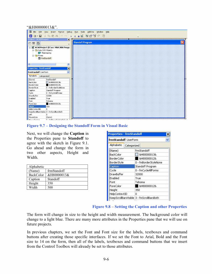
Figure 9.7 � Designing the Standoff Form in Visual Basic Next, we will change the Caption in the Properties pane to Standoff to agree with the sketch in Figure 9.1. Go ahead and change the form in two other aspects, Height and Width.
Alphabetic (Name) frmStandoff BackColor &H80000013& Caption Standoff Height 350 Width 500
Figure 9.8 � Setting the Caption and other Properties The form will change in size to the height and width measurement. The background color will change to a light blue. There are many more attributes in the Properties pane that we will use on future projects. In previous chapters, we set the Font and Font size for the labels, textboxes and command buttons after creating those specific interfaces. If we set the Font to Arial, Bold and the Font size to 14 on the form, then all of the labels, textboxes and command buttons that we insert from the Control Toolbox will already be set to those attributes.

9-7
On the left side of the Visual Basic Editor, locate the property that controls the font and font size in the Properties window. When highlighting the row for Font, a small command button with three small dots appears to the right of the default font name of Tahoma. Click on the three dotted button to open the Visual Basic Font window.
Figure 9.9 � Changing the Font We will select the Arial font, Regular font style and 16 size for this project to agree with the initial sketch if the user input form. When we adjust the attributes for the label, these changes do not alter globally for the other objects on the form. If we wish to underline the text or phrase in the label, add a check to the Underline checkbox in the Effects section of the Font window. When we finish making changes to the font property, select the OK command button to return to the work area.
Figure 9.10 � The Font Window in Visual Basic
Creating and Inserting an Image into a Form in Visual Basic _________________________________________________________ As in previous chapters, this form will have a picture of the part that we will create automatically, so we need to make a drawing of part in AutoCAD. Dimension the drawing as we do in any other drawing, but we will use the Edit Text tool to remove the actual dimension and write in the variable name that matches the textbox label. In Figure 9.11, we show dimensions that associate with the across flats (AF), inside diameter (ID) and Length textboxes. When the drawing is finished, we need to save the drawing as an image file. Use the Saveimg command to save file on the VBA Programs folder. Create a folder named Images in the VBA Programs folder and save the file as the same name as the program for matching purposes, Standoff. We saved the file as a Bitmap with a width of 312 pixels and a height of 210 pixels.

9-8
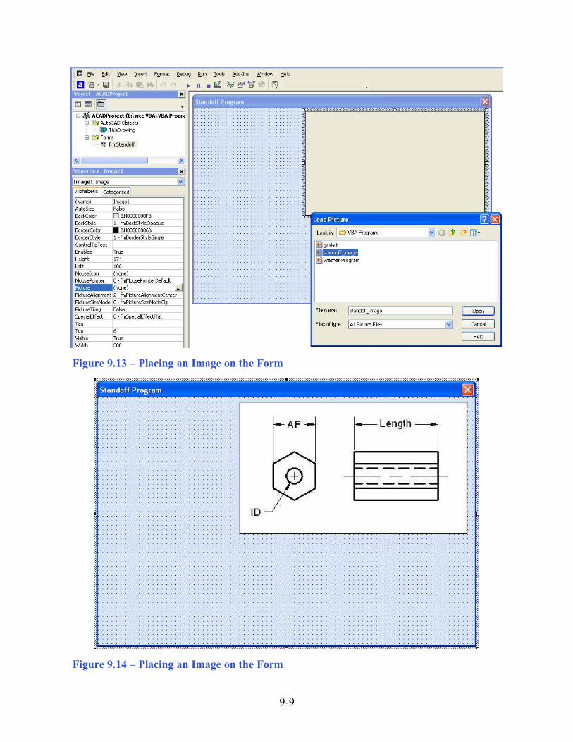
Figure 9.11 � Creating the Standoff Form Image in AutoCAD On the control toolbox, select the Image tool and then draw a rectangular box on the form in the upper right corner as shown in Figure 9.13. After outlining the size of the image, we will direct the program to the folder and filename of the digital image. In the Properties � Image pane, select the attribute named Picture. With the mouse, select the three dot box in the empty cell to the right of Picture. The Load Picture window appears on the screen. Go to the VBA Programs folder and then the Images folder. Select the file, Standoff and it will appear in the picture frame.
Figure 9.12 � The Control Toolbox In the Properties pane set the image name to ImgStandoff, the width to 300 and the height to 174. The image will finally appear as shown in Figure 9.14.
9-9
Figure 9.13 � Placing an Image on the Form
Figure 9.14 � Placing an Image on the Form
9-10
Inserting a Label into a Form _________________________________________________________
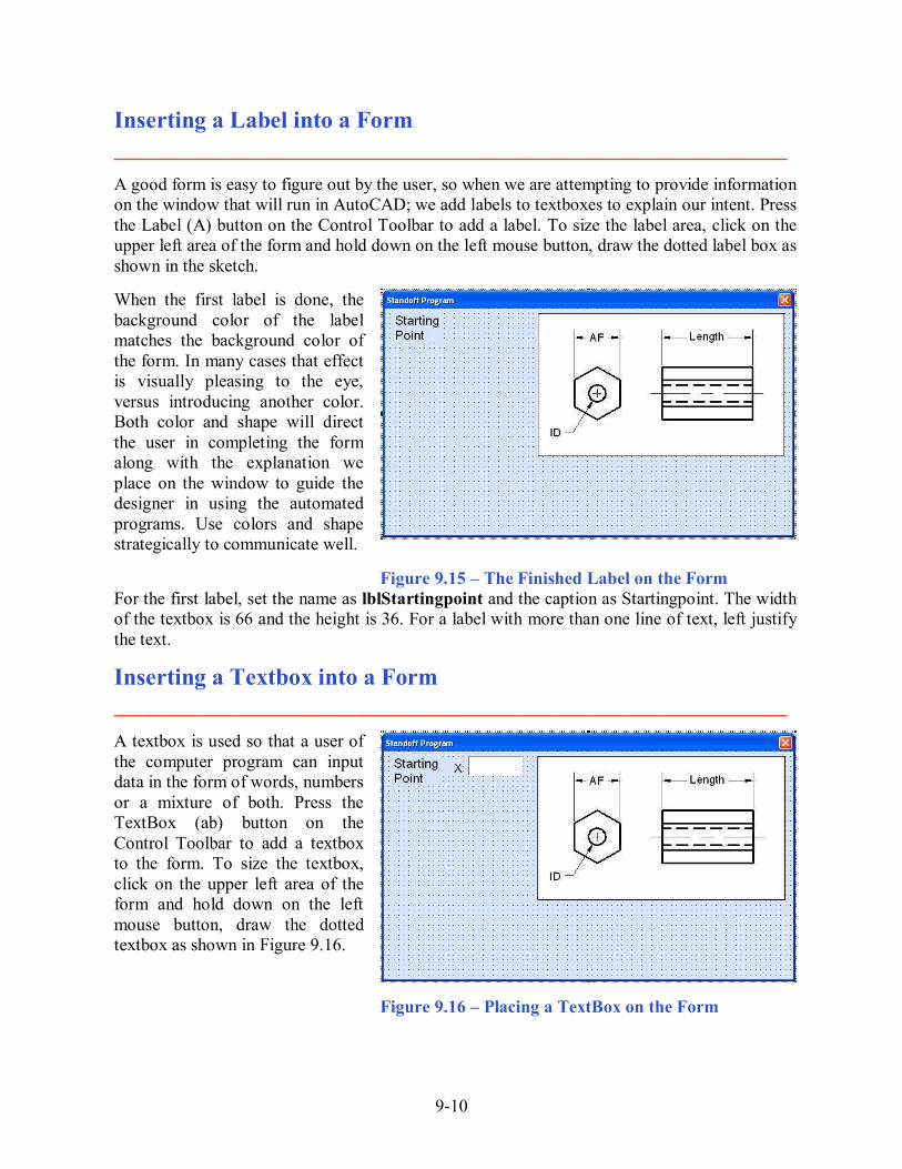
A good form is easy to figure out by the user, so when we are attempting to provide information on the window that will run in AutoCAD; we add labels to textboxes to explain our intent. Press the Label (A) button on the Control Toolbar to add a label. To size the label area, click on the upper left area of the form and hold down on the left mouse button, draw the dotted label box as shown in the sketch.
When the first label is done, the background color of the label matches the background color of the form. In many cases that effect is visually pleasing to the eye, versus introducing another color. Both color and shape will direct the user in completing the form along with the explanation we place on the window to guide the designer in using the automated programs. Use colors and shape strategically to communicate well.
Figure 9.15 � The Finished Label on the Form
For the first label, set the name as lblStartingpoint and the caption as Startingpoint. The width of the textbox is 66 and the height is 36. For a label with more than one line of text, left justify the text.
Inserting a Textbox into a Form _________________________________________________________
A textbox is used so that a user of the computer program can input data in the form of words, numbers or a mixture of both. Press the TextBox (ab) button on the Control Toolbar to add a textbox to the form. To size the textbox, click on the upper left area of the form and hold down on the left mouse button, draw the dotted textbox as shown in Figure 9.16.
Figure 9.16 � Placing a TextBox on the Form

9-11
We will name the textbox using the three letter prefix txt followed by the name or phrase of the tool. For our first textbox, the name is txtSpX.
Alphabetic (Name) txtSpX Height 24 Width 66
We place a Label using a common Visual Basic naming convention lblSpX just to the left of the Textbox. The Caption for the Label will be X. On all of the labels that are just to the left of the Textboxes, we will align the text to the right by setting the TextAlign property to right align.
Figure 9.17 � Changing the (Name) to txtName We will add another TextBox named txtSpY under the first one and the Label to the left of the textbox is called lblSpY. The Caption for the Label will be Y. We will add yet another TextBox named txtSpZ under the first one and the Label to the left of the textbox is called lblSpZ. The Caption for the Label will be Z.
Figure 9.18 � Adding the Y and Z Textboxes We will add three more textboxes to the form named txtAF, txtID, and txtLength. The labels to the left of the textbox are called lblAF, lblID, and lblLength. The Captions for the Labels are shown in Figure 9.19.
Figure 9.19 � Adding the Last Six Textboxes

9-12
Inserting a Command Buttons into a Form _________________________________________________________ A command button is used so that a user will execute the application. Press the Command button on the Control Toolbar to add a command button. To size the label area, click on the upper left area of the form and hold down on the left mouse button, draw the command button as shown in Figure 9.20.
Figure 9.20 � Insert a Command Button onto a Form
We will name the command button using the name is cmdDraw.
Alphabetic (Name) cmdDraw Caption Draw Font Arial Height 30 Width 72
The font we want for the Command Button is 16 point, Arial Bold. When highlighting the row for Font, a small command button with three small dots appears to the right of the font name of Arial Narrow. Click on the three dotted button to open the Visual Basic Font window. Make the changes as we did before and press OK to save the property.
Figure 9.21 � Changing the (Name) to cmdDraw

9-13
Add a second Command button; named cmdClear is for clearing the Starting point�s X, Y, Z coordinates, AF, ID, and Length textboxes. The third command button is to exit the program. When the user presses the Exit command button, the application closes and full control of the manual AutoCAD program returns to the user. Notice the equal spacing between the command buttons gives a visually friendly appearance.
Figure 9.22 � Insert Two More Command Buttons
The fourth command button is Pick Point, which we will name cmdPickPoint. We draw the button as shown in figure 9.22 and after typing Pick for the caption, press Shift Enter and type Point on the second line. Center the text. When we code for this command button, we will allow the user to select a point on the graphical display and the X, Y and Z coordinates will appear in their specific textboxes.
Adding a Copyright Statement to a Form _________________________________________________________ At the beginning of a new program, we will expect to see an explanation or any special instructions in the form of comments such as copyright, permissions or other legal notices to inform programmers what are the rules dealing with running the code. Comments at the opening of the code could help an individual determine whether the program is right for their application or is legal to use. The message box is a great tool when properly utilized to inform someone if they are breaking a copyright law when running the code. Finish the form with the following copyright information. �Standoff Program.dvb - copyright (c) 2008 by Charles Robbins. All Rights Reserved. If there are special rules or instructions that the user needs to know, place that information on the bottom of the form. Figure 9.23 � Adding a Copyright Statement

9-14
Now that the form is complete, we will begin to write the code that actually interfaces the content of the form using logic and computations to draw the stamping in the AutoCAD graphical display. We will begin the program with comments and place addition phrases throughout the program to assist ourselves or others in the future when modifying the code.
Adding Comments in Visual Basic to Communicate the Copyright _________________________________________________________ The comments we placed in the first three lines of the program will inform the individual opening and reading the code, but those user that may run the application without checking, the label on the bottom of the form with the copyright information is a great tool to alert the client to the rules of the program and what will the application do. To begin the actual coding of the program, double click on the Draw command button to enter the programming list. At the top of the program and before the line of code with Sub CreateStandoff (), place the following comments with the single quote (�) character. Remember, the single quote character (�) will precede a comment and when the code is compiled, comments are ignored. Type the following line of code: Sub CreateStandoff () 'standoff.dvb.copyright (c) 2008 by Charles Robbins 'This program will draws a standoff that has a hole drilled through it 'after inputting an across flats (AF), internal diameter (ID) and Length
Figure 9.24 � Adding Comments into the Code
Declaring Variables in a Program with the Dimension Statement _________________________________________________________
When we are going to use a number, text string or object that may change throughout the life of the code, we create a variable to hold the value of that changing entity. In Visual Basic, the dimension or dim statement is one of the ways to declare a variable at the script of procedure level. The other two ways are the Private and Public statements, which we will use in later chapters. In Figure 9.25, we have a drawing that shows an X and Y grid for each point we need to draw. In this program, we only need points 1 through 13. To create the points, we have made a grid with the values of x1 through x6 horizontally on the bottom and y1 through y5 vertically on the left. In the program, we will define point P1 as coordinate (x1, y1, z1), point P2 as (x2, y5, z1)

9-15
and so forth. We have found that points are easily defined using this method and therefore explaining the algebra in the program is simpler.
Figure 9.25 � Identifying the Variables for the Standoff Program
In our program, we will declare a variable to enable us to draw lines and circles, a variable for each vertex and a variable for each textbox. As we can see below, the made up name objCircle is an AutoCAD Circle by definition and the contrived name objLine is a line. To mirror the five lines in the right orthographic view of the drawing, we have made three addition variables, objSs1, objDrawingObject and objMirroredObject. The first is for creating a selection set, the second is to hold drawing objects and the last is for mirroring the objects. We will cover the selecting and mirroring code later in the chapter. We will set variables for array (objArrayedObject), the linetypes (objLinetype) and layers (objLayers). Then, we declare variables of the textboxes OD, ID and W as double integers (As Double). For the three dimensions on the drawing we declare objDimension as an AutoCAD dimension. Type the following lines of code after the comment. 'Define the point arrays, the variables, and entities Dim objLinetype As AcadLineType Dim objLayer As AcadLayer Dim objLine As AcadLine Dim objCircle As AcadCircle Dim objSs1 As AcadSelectionSet Dim objMirroredObject As AcadEntity

9-16
Dim objArrayedObject As AcadEntity Dim objDrawingObject As AcadEntity Dim objDimension As AcadDimension Dim AF As Double Dim ID As Double Dim Length As Double Dim P1(0 To 2) As Double Dim P2(0 To 2) As Double Dim P3(0 To 2) As Double Dim P4(0 To 2) As Double Dim P5(0 To 2) As Double Dim P6(0 To 2) As Double Dim P7(0 To 2) As Double Dim P8(0 To 2) As Double Dim P9(0 To 2) As Double Dim P10(0 To 2) As Double Dim P11(0 To 2) As Double Dim P12(0 To 2) As Double Dim P13(0 To 2) As Double Dim P14(0 To 2) As Double Dim P15(0 To 2) As Double Dim P16(0 To 2) As Double Dim P17(0 To 2) As Double Dim P18(0 To 2) As Double Dim x1 As Double Dim x2 As Double Dim x3 As Double Dim x4 As Double Dim x5 As Double Dim x6 As Double Dim x7 As Double Dim x8 As Double Dim y1 As Double Dim y2 As Double Dim y3 As Double Dim y4 As Double Dim y5 As Double Dim y6 As Double Dim z1 As Double Dim pi As Double The vertices or points are declared as double integers (As Double) with an array of zero to two (0 to 2). The vertex P1(0) represents the X coordinate, the P1(1) represents the Y coordinate and P1(2) represents the Z coordinate. Some may think that it is a waste of time to involve the Z-axis in a two dimension drawing, but we will incorporate the Z coordinate for designers that work in all three dimensions. For everyone else, we will just enter zero (0) in the Z coordinate textbox. We will declare points P1 through P18 for the vertices in the drawing in Figure 9.25.

9-17
As discussed previously, we have given the Standoff drawing problem a grid, so we declare x1 through x8, y1 through y6, and z1. To compute angles, we declare pi in this program.
Figure 9.26 � Declaring Variables with Dim Statements Remember, when selecting variable names, they should be a word or a phrase without spaces that represents the value that the variable contains. If we want to hold a value of one�s date of birth, we can call the variable, DateofBirth. The keywords Date and Birth are in sentence case with the first letter capitalized. There are no spaces in the name. Some programmers use the underscore character (_) to separate words in phrases. This is acceptable, but a double underscore (__) can cause errors if we do not detect the repeated character.
9-18
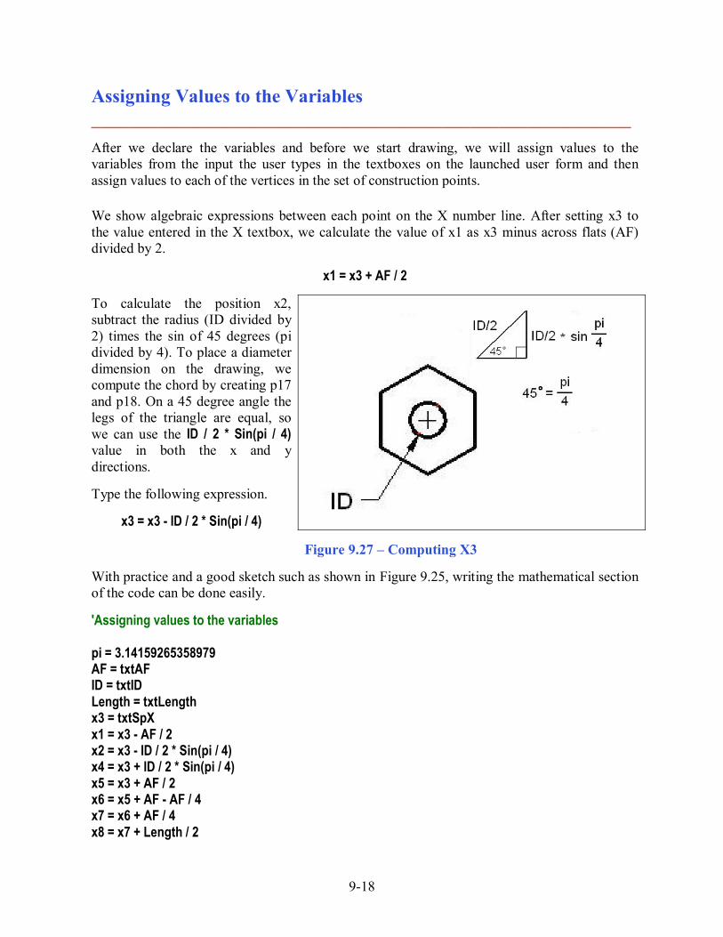
Assigning Values to the Variables _________________________________________________________ After we declare the variables and before we start drawing, we will assign values to the variables from the input the user types in the textboxes on the launched user form and then assign values to each of the vertices in the set of construction points.
We show algebraic expressions between each point on the X number line. After setting x3 to the value entered in the X textbox, we calculate the value of x1 as x3 minus across flats (AF) divided by 2.
x1 = x3 + AF / 2
To calculate the position x2, subtract the radius (ID divided by 2) times the sin of 45 degrees (pi divided by 4). To place a diameter dimension on the drawing, we compute the chord by creating p17 and p18. On a 45 degree angle the legs of the triangle are equal, so we can use the ID / 2 * Sin(pi / 4) value in both the x and y directions. Type the following expression.
x3 = x3 - ID / 2 * Sin(pi / 4)
Figure 9.27 � Computing X3 With practice and a good sketch such as shown in Figure 9.25, writing the mathematical section of the code can be done easily. 'Assigning values to the variables pi = 3.14159265358979 AF = txtAF ID = txtID Length = txtLength x3 = txtSpX x1 = x3 - AF / 2 x2 = x3 - ID / 2 * Sin(pi / 4) x4 = x3 + ID / 2 * Sin(pi / 4) x5 = x3 + AF / 2 x6 = x5 + AF - AF / 4 x7 = x6 + AF / 4 x8 = x7 + Length / 2

9-19
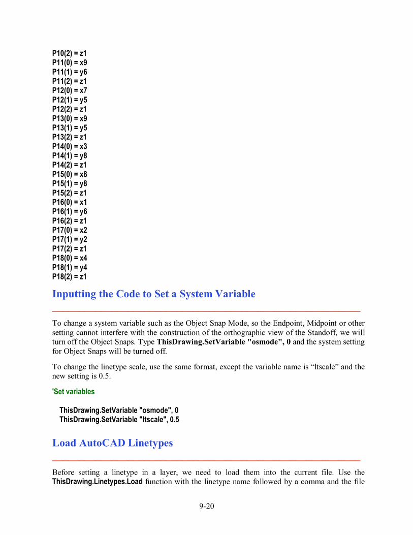
x9 = x7 + Length x10 = x9 + AF / 4 y3 = txtSpY y1 = y3 - AF / 2 / Sqr(3) y2 = y3 - ID / 2 * Sin(pi / 4) y4 = y3 + ID / 2 * Sin(pi / 4) y5 = y3 + ID / 2 y6 = y3 + AF / 2 / Sqr(3) y7 = y3 + AF / Sqr(3) y8 = y7 + AF z1 = txtSpZ We use the same sketch to make the point assignments. Just review the data from Figure 9.25 and make the correct coordinate designation as shown. Remember that P1(0) is the x position, P1(1) is the y position and P1(2) is the z position. 'Point assignments P1(0) = x3 P1(1) = y3 P1(2) = z1 P2(0) = x5 P2(1) = y1 P2(2) = z1 P3(0) = x5 P3(1) = y6 P3(2) = z1 P4(0) = x6 P4(1) = y3 P4(2) = z1 P5(0) = x10 P5(1) = y3 P5(2) = z1 P6(0) = x7 P6(1) = y3 P6(2) = z1 P7(0) = x9 P7(1) = y3 P7(2) = z1 P8(0) = x9 P8(1) = y7 P8(2) = z1 P9(0) = x7 P9(1) = y7 P9(2) = z1 P10(0) = x7 P10(1) = y6
9-20
P10(2) = z1 P11(0) = x9 P11(1) = y6 P11(2) = z1 P12(0) = x7 P12(1) = y5 P12(2) = z1 P13(0) = x9 P13(1) = y5 P13(2) = z1 P14(0) = x3 P14(1) = y8 P14(2) = z1 P15(0) = x8 P15(1) = y8 P15(2) = z1 P16(0) = x1 P16(1) = y6 P16(2) = z1 P17(0) = x2 P17(1) = y2 P17(2) = z1 P18(0) = x4 P18(1) = y4 P18(2) = z1
Inputting the Code to Set a System Variable _________________________________________________________ To change a system variable such as the Object Snap Mode, so the Endpoint, Midpoint or other setting cannot interfere with the construction of the orthographic view of the Standoff, we will turn off the Object Snaps. Type ThisDrawing.SetVariable "osmode", 0 and the system setting for Object Snaps will be turned off. To change the linetype scale, use the same format, except the variable name is �ltscale� and the new setting is 0.5. 'Set variables ThisDrawing.SetVariable "osmode", 0 ThisDrawing.SetVariable "ltscale", 0.5
Load AutoCAD Linetypes _________________________________________________________ Before setting a linetype in a layer, we need to load them into the current file. Use the ThisDrawing.Linetypes.Load function with the linetype name followed by a comma and the file
9-21
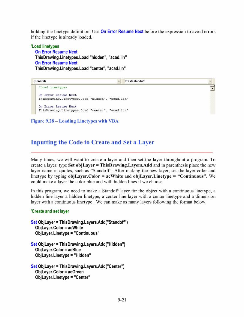
holding the linetype definition. Use On Error Resume Next before the expression to avoid errors if the linetype is already loaded. 'Load linetypes On Error Resume Next ThisDrawing.Linetypes.Load "hidden", "acad.lin" On Error Resume Next ThisDrawing.Linetypes.Load "center", "acad.lin"
Figure 9.28 � Loading Linetypes with VBA
Inputting the Code to Create and Set a Layer _________________________________________________________ Many times, we will want to create a layer and then set the layer throughout a program. To create a layer, type Set objLayer = ThisDrawing.Layers.Add and in parenthesis place the new layer name in quotes, such as �Standoff�. After making the new layer, set the layer color and linetype by typing objLayer.Color = acWhite and objLayer.Linetype = �Continuous�. We could make a layer the color blue and with hidden lines if we choose. In this program, we need to make a Standoff layer for the object with a continuous linetype, a hidden line layer a hidden linetype, a center line layer with a center linetype and a dimension layer with a continuous linetype . We can make as many layers following the format below.
'Create and set layer Set ObjLayer = ThisDrawing.Layers.Add("Standoff") ObjLayer.Color = acWhite ObjLayer.Linetype = "Continuous" Set ObjLayer = ThisDrawing.Layers.Add("Hidden") ObjLayer.Color = acBlue ObjLayer.Linetype = "Hidden" Set ObjLayer = ThisDrawing.Layers.Add("Center") ObjLayer.Color = acGreen ObjLayer.Linetype = "Center"

9-22
Set ObjLayer = ThisDrawing.Layers.Add("Dimension") ObjLayer.Color = acRed ObjLayer.Linetype = "Continuous" To set the layer current, before drawing an entity, we would type:
ThisDrawing.ActiveLayer = ThisDrawing.Layers("Standoff")
Figure 9.29 �Creating and Setting an AutoCAD Layer
Inputting the Code to Draw in Visual Basic _________________________________________________________ Now we want to enter the code that will actually draw the five lines in AutoCAD Model Space. We use the Set function to draw a line by typing Set ObjLine and then we tell the computer that it will draw in Modelspace by adding a line from point P7 to point P8. Draw the next three lines from P8 to P9, from P9 to P6 and from P10 to P11. Go ahead and type the following comments and drawing code: 'Draw four lines Set ObjLine = ThisDrawing.ModelSpace.AddLine(P7, P8) Set ObjLine = ThisDrawing.ModelSpace.AddLine(P8, P9) Set ObjLine = ThisDrawing.ModelSpace.AddLine(P9, P6) Set ObjLine = ThisDrawing.ModelSpace.AddLine(P10, P11)

9-23
'Draw hidden line ThisDrawing.ActiveLayer = ThisDrawing.Layers("Hidden") Set ObjLine = ThisDrawing.ModelSpace.AddLine(P12, P13) The last line on the right orthographic view is the hidden line from P12 to P13. We change the layer by entering, ThisDrawing.ActiveLayer = ThisDrawing.Layers("Hidden") before the line code.
Using Selection Sets and Mirroring in Visual Basic _________________________________________________________ Before we mirror the five lines across the vertical centerline, we will select the five objects using the Select all function, First, we define a temporary selection set called objSs1 by typing Set objSs1 = ThisDrawing.SelectionSets.Add("TempSS") and then we select the five entities using objSs1.Select (acSelectionSetAll). To mirror the three objects in objSs1, we key the following code:
For Each ObjDrawingObject In ObjSs1 Set ObjMirroredObject = ObjDrawingObject.Mirror(P4, P5) ObjMirroredObject.Update Next ObjSs1.Delete
We will always input the mirror function as shown, only changing the name of the selection set containing the entities or changing the points on the mirror line. In the next macro, we will mirror the four arcs and two lines across the horizontal centerline defined by P4 and P5. The last step in the process is to delete the selection set with objSs1.Delete. Type Set objLine = ThisDrawing.ModelSpace.AddLine(P3, P4) to place the last centerline which is in the right orthographic view from points P3 to P4. Before the code for the centerline, type ThisDrawing.ActiveLayer = ThisDrawing.Layers("Center")
Drawing and Arraying a Line _________________________________________________________ Like mirroring, we array entities by selecting the object. This time we zoom all to have the centerline appear in the graphical display, and then use acSelectionSetLast to retrieve the last entity drawn. When we array the centerline, we type:
Set objArrayedObject = objDrawingObject.ArrayPolar(6, 2 * 3.14159265358979, P1) Where the 6 is the number of objects in the array in the hexagon shape, the 2 * 3.14159265358979 represents 2 times pi or 360 degrees. P1 is the center point of the array. After the array, we delete the selection set objSs1.

9-24
'Draw line to be arrayed ThisDrawing.ActiveLayer = ThisDrawing.Layers("Standoff") Set ObjLine = ThisDrawing.ModelSpace.AddLine(P2, P3) 'Array the centerline around sp ThisDrawing.Application.ZoomAll Set ObjSs1 = ThisDrawing.SelectionSets.Add("TempSS") ObjSs1.Select (acSelectionSetLast) For Each ObjDrawingObject In ObjSs1 Set objArrayedOobject = ObjDrawingObject.ArrayPolar(6, 2 * 3.14159265358979, P1) ObjMirroredObject.Update Next ObjSs1.Delete End Sub
Drawing the Circle in Visual Basic _________________________________________________________ We use the Set function to draw a circle by typing Set ObjCircle and then we tell the computer that it will draw in Modelspace by adding a circle from the center point P1 with a radius that contains the value from the Inside Diameter (ID) textbox divided by 2. 'Draw the circle Set ObjCircle = ThisDrawing.ModelSpace.AddCircle(P1, ID / 2)
Dimensioning with VBA _________________________________________________________ To place a linear or aligned dimension on a drawing is very simple now that we have created points to place the measurements. First, we change the current layer to �dimension� and add the Length quantity on the right view with this expression.
Set objDimension = ThisDrawing.ModelSpace.AddDimAligned (P8, P9, P15) P8 and P9 are the points where the dimension extension lines attach. P15 is the point where the dimension text is located. The AddDimDiametric function allows us to place two points of the circle that will define the diameter and the last value is the length of the leader. Type
Set objDimension = ThisDrawing.ModelSpace.AddDimDiametric (P17, P18, AF)
The direction of the points determine the side of the hole that the leader is on. Type the dimension code:

9-25
'Dimension the standoff ThisDrawing.ActiveLayer = ThisDrawing.Layers ("dimension") Set objDimension = ThisDrawing.ModelSpace.AddDimAligned (P8, P9, P15) Set objDimension = ThisDrawing.ModelSpace.AddDimAligned (P16, P3, P14) Set objDimension = ThisDrawing.ModelSpace.AddDimDiametric (P17, P18, AF) To end this Visual Basic subroutine, we will type a comment saying so. We will exit the program after drawing the standoff. Type the following code: 'Turn off the Standoff Window and end the program Unload Me End End Sub
Resetting the Data with the cmdClear Command Button _________________________________________________________ To clear the textboxes containing the user input, we will first set the textbox for txtXcoord, txtXcoord.text property to a �0.00� entry by using the equal sign �=�.This makes the property equal zero as a default. We do this also for the Y and Z coordinates. We will set the textboxes for txtWidth, txtWidth.text property to a black entry by using the equal sign �=� and the null string ��, and this will make that property blank. Notice that after the control object name the dot (.) separates the suffix which is the name of the property for that object. Key the following code as a new subroutine Private Sub cmdClear_Click(). Private Sub cmdClear_Click() 'clear the form txtSpX = "0" txtSpY = "0" txtSpZ = "0" txtAF = "0" txtID = "0" txtLength = "0" End Sub
Figure 9.30 � Computing the Reset Button by Clearing Textboxes
9-26
Exiting the Program with the cmdExit Command Button _________________________________________________________ To exit this program, we will unload the application and end the program. Type the following code: Private Sub cmdExit_Click() 'unload and end program Unload Me End End Sub
Figure 9.31 � Coding the Exit Button
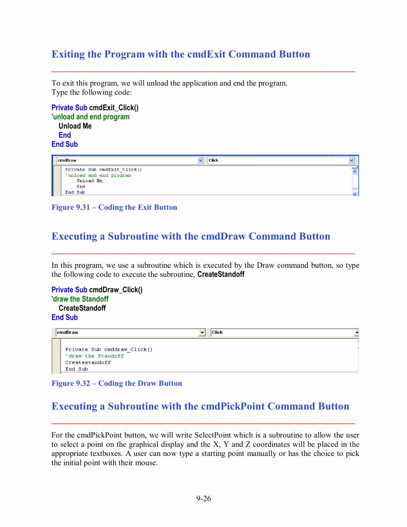
Executing a Subroutine with the cmdDraw Command Button _________________________________________________________ In this program, we use a subroutine which is executed by the Draw command button, so type the following code to execute the subroutine, CreateStandoff Private Sub cmdDraw_Click() 'draw the Standoff CreateStandoff End Sub
Figure 9.32 � Coding the Draw Button
Executing a Subroutine with the cmdPickPoint Command Button _________________________________________________________ For the cmdPickPoint button, we will write SelectPoint which is a subroutine to allow the user to select a point on the graphical display and the X, Y and Z coordinates will be placed in the appropriate textboxes. A user can now type a starting point manually or has the choice to pick the initial point with their mouse.

9-27
Private Sub cmdPickPoint_Click() SelectPoint End Sub The SelectPoint subroutine starts with hiding the Standoff window and the prompt "Pick a Start Point: " is written on the command line. Once the single point is selected, the txtSpX textbox is given the first value of the starting point. After all three txtSP textboxes are filled, the Standoff window reappears. Sub SelectPoint() Me.hide Dim StartPoint As Variant StartPoint = ThisDrawing.Utility.GetPoint(, vbCr & "Pick a Start Point: ") txtSpX = StartPoint(0) txtSpY = StartPoint(1) txtSpZ = StartPoint(2) Me.Show End Sub Written below is the entire program for creating the Standoff. Private Sub cmdClear_Click() 'clear the form txtSpX = "0" txtSpY = "0" txtSpZ = "0" txtAF = "0" txtID = "0" txtLength = "0" End Sub Private Sub cmddraw_Click() 'draw the Standoff Createstandoff End Sub Private Sub cmdexit_Click() 'unload and end program Unload Me End End Sub Sub Createstandoff() 'standoff.dvb.copyright (c) 2008 by Charles Robbins 'This program will draws a standoff that has a hole drilled through it 'after inputting an across flats (AF), internal diameter (ID) and Length 'identifying variables

9-28
Dim objLinetype As AcadLineType Dim objLayer As AcadLayer Dim objLine As AcadLine Dim objCircle As AcadCircle Dim objSs1 As AcadSelectionSet Dim objMirroredObject As AcadEntity Dim objArrayedObject As AcadEntity Dim objDrawingObject As AcadEntity Dim objDimesnion As AcadDimension Dim AF As Double Dim ID As Double Dim Length As Double Dim P1(0 To 2) As Double Dim P2(0 To 2) As Double Dim P3(0 To 2) As Double Dim P4(0 To 2) As Double Dim P5(0 To 2) As Double Dim P6(0 To 2) As Double Dim P7(0 To 2) As Double Dim P8(0 To 2) As Double Dim P9(0 To 2) As Double Dim P10(0 To 2) As Double Dim P11(0 To 2) As Double Dim P12(0 To 2) As Double Dim P13(0 To 2) As Double Dim P14(0 To 2) As Double Dim P15(0 To 2) As Double Dim P16(0 To 2) As Double Dim P17(0 To 2) As Double Dim P18(0 To 2) As Double Dim x1 As Double Dim x2 As Double Dim x3 As Double Dim x4 As Double Dim x5 As Double Dim x6 As Double Dim x7 As Double Dim x8 As Double Dim y1 As Double Dim y2 As Double Dim y3 As Double Dim y4 As Double Dim y5 As Double Dim y6 As Double Dim z1 As Double Dim pi As Double

9-29
'Assigning values to the variables pi = 3.14159265358979 AF = txtAF ID = txtID Length = txtLength x3 = txtSpX x1 = x3 - AF / 2 x2 = x3 - ID / 2 * Sin(pi / 4) x4 = x3 + ID / 2 * Sin(pi / 4) x5 = x3 + AF / 2 x6 = x5 + AF - AF / 4 x7 = x6 + AF / 4 x8 = x7 + Length / 2 x9 = x7 + Length x10 = x9 + AF / 4 y3 = txtSpY y1 = y3 - AF / 2 / Sqr(3) y2 = y3 - ID / 2 * Sin(pi / 4) y4 = y3 + ID / 2 * Sin(pi / 4) y5 = y3 + ID / 2 y6 = y3 + AF / 2 / Sqr(3) y7 = y3 + AF / Sqr(3) y8 = y7 + AF z1 = txtSpZ 'Point assignments P1(0) = x3 P1(1) = y3 P1(2) = z1 P2(0) = x5 P2(1) = y1 P2(2) = z1 P3(0) = x5 P3(1) = y6 P3(2) = z1 P4(0) = x6 P4(1) = y3 P4(2) = z1 P5(0) = x10 P5(1) = y3 P5(2) = z1 P6(0) = x7 P6(1) = y3 P6(2) = z1 P7(0) = x9

9-30
P7(1) = y3 P7(2) = z1 P8(0) = x9 P8(1) = y7 P8(2) = z1 P9(0) = x7 P9(1) = y7 P9(2) = z1 P10(0) = x7 P10(1) = y6 P10(2) = z1 P11(0) = x9 P11(1) = y6 P11(2) = z1 P12(0) = x7 P12(1) = y5 P12(2) = z1 P13(0) = x9 P13(1) = y5 P13(2) = z1 P14(0) = x3 P14(1) = y8 P14(2) = z1 P15(0) = x8 P15(1) = y8 P15(2) = z1 P16(0) = x1 P16(1) = y6 P16(2) = z1 P17(0) = x2 P17(1) = y2 P17(2) = z1 P18(0) = x4 P18(1) = y4 P18(2) = z1 'Turn off object snaps and set linetype scale ThisDrawing.SetVariable "osmode", 0 ThisDrawing.SetVariable "ltscale", 0.5 'Load linetypes On Error Resume Next ThisDrawing.Linetypes.Load "hidden", "acad.lin" On Error Resume Next ThisDrawing.Linetypes.Load "center", "acad.lin"

9-31
'Create and set layer Set objLayer = ThisDrawing.Layers.Add("Standoff") objLayer.Color = acWhite objLayer.Linetype = "Continuous" Set objLayer = ThisDrawing.Layers.Add("Hidden") objLayer.Color = acBlue objLayer.Linetype = "Hidden" Set objLayer = ThisDrawing.Layers.Add("Center") objLayer.Color = acGreen objLayer.Linetype = "Center" Set objLayer = ThisDrawing.Layers.Add("Dimension") objLayer.Color = acRed objLayer.Linetype = "Continuous" ThisDrawing.ActiveLayer = ThisDrawing.Layers("Standoff") 'Draw four line Set objLine = ThisDrawing.ModelSpace.AddLine(P7, P8) Set objLine = ThisDrawing.ModelSpace.AddLine(P8, P9) Set objLine = ThisDrawing.ModelSpace.AddLine(P9, P6) Set objLine = ThisDrawing.ModelSpace.AddLine(P10, P11) 'Draw hidden line ThisDrawing.ActiveLayer = ThisDrawing.Layers("Hidden") Set objLine = ThisDrawing.ModelSpace.AddLine(P12, P13) 'Mirror the line across horizontal centerline Set objSs1 = ThisDrawing.SelectionSets.Add("TempSS") objSs1.Select (acSelectionSetAll) For Each objDrawingObject In objSs1 Set objMirroredObject = objDrawingObject.Mirror(P4, P5) objMirroredObject.Update Next objSs1.Delete 'draw centerlines ThisDrawing.ActiveLayer = ThisDrawing.Layers("Center") Set objLine = ThisDrawing.ModelSpace.AddLine(P4, P5) 'Draw the circle ThisDrawing.ActiveLayer = ThisDrawing.Layers("Standoff") Set objCircle = ThisDrawing.ModelSpace.AddCircle(P1, ID / 2)
9-32
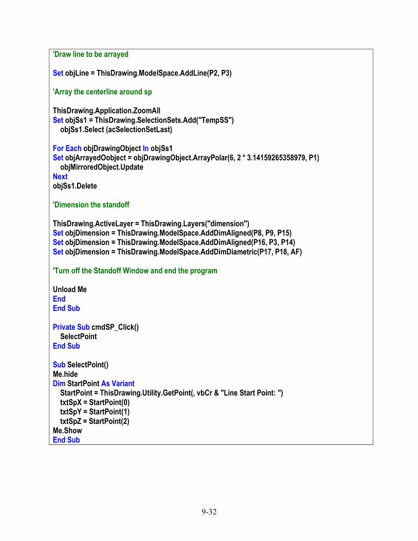
'Draw line to be arrayed Set objLine = ThisDrawing.ModelSpace.AddLine(P2, P3) 'Array the centerline around sp ThisDrawing.Application.ZoomAll Set objSs1 = ThisDrawing.SelectionSets.Add("TempSS") objSs1.Select (acSelectionSetLast) For Each objDrawingObject In objSs1 Set objArrayedOobject = objDrawingObject.ArrayPolar(6, 2 * 3.14159265358979, P1) objMirroredObject.Update Next objSs1.Delete 'Dimension the standoff ThisDrawing.ActiveLayer = ThisDrawing.Layers("dimension") Set objDimension = ThisDrawing.ModelSpace.AddDimAligned(P8, P9, P15) Set objDimension = ThisDrawing.ModelSpace.AddDimAligned(P16, P3, P14) Set objDimension = ThisDrawing.ModelSpace.AddDimDiametric(P17, P18, AF) 'Turn off the Standoff Window and end the program Unload Me End End Sub Private Sub cmdSP_Click() SelectPoint End Sub Sub SelectPoint() Me.hide Dim StartPoint As Variant StartPoint = ThisDrawing.Utility.GetPoint(, vbCr & "Line Start Point: ") txtSpX = StartPoint(0) txtSpY = StartPoint(1) txtSpZ = StartPoint(2) Me.Show End Sub

9-33
Inserting a Module into a Visual Basic Application _________________________________________________________ Insert a Module by selecting Insert on the Menu Bar and select Module as shown in Figure 9.33. In the Project Menu, double click on the Module and type the following code. Sub DrawStandoff () 'draw the Standoff frmStandoff.Show End Sub Figure 9.33 � Inserting a Module The line of code, frmStandoff.Show will display the form at the beginning of the program.
Figure 9.34 � Coding the Module
Running the Program _________________________________________________________ After noting that the program is saved, press the F5 to run the Standoff application. The Standoff window will appear on the graphical display in AutoCAD as shown in figure 9.35. Type the data shown in figure 9.36 or something similar into the textboxes and select the Draw Command Button to execute the program. Figure 9.35 � Launching the Program If we wish to select a point on the graphical display to enter the X, Y and Z values, press the Pick Point command button and do so.

9-34
To exit the program, press the Exit command button on the Standoff Program window. In AutoCAD, the drawing of the finished Standoff will appear as shown in Figure 9.37.
X 3 Y 5 Z 0
AF 1 ID 0.5
Length 3
Figure 9.36 � Input Data
There are many variations of this Visual Basic Application we can practice and draw many single view orthographic drawings. While we are practicing with forms, we can learn how to use variables, make point assignments and draw just about anything we desire. These are skills that we want to commit to memory.
Figure 9.37 � The Finished Draw * World Class CAD Challenge 5-9 * - Write a Visual Basic Application that draws and dimensions a Standoff with a front and right view by inputting data in a form. Complete the program in less than 120 minutes to maintain your World Class ranking.
Continue this drill four times making other shapes and simple orthographic views with lines and circles, each time completing the Visual Basic Application in less than 120 minutes to maintain your World Class ranking.