din timers td - imo website
TRANSCRIPT

DIN Timers TD
Key Features• 17.5mm or 22.5mm DIN Rail mounting Electronic Timers
• Wide coil operation, 12V to 320V AC/DC
• Multi time range / Multi function
• ON-Delay, OFF-Delay, Asymetrical, Star/Delta versions
• Perfect to fit in modular enclosure
• Protection against overvoltage and reverse polarity
• Self-extinguishing plastic housing
Options & Ordering Codes
TDM10-12 TDM10 TDAS TDSD1
Operation Modes A, B, C, D, E, F, G, H, I, K ND, FD, NFD, Fon, Foff Star Delta
Time Range 0.1 sec - 10 days 0.1 sec - 10 days 0.1 sec - 10 days 1-30 sec / ∆20-500ms
Accuracy 30ppm
Supply Voltage 12V AC/DC / 180-265V AC 24-300V AC/DC, ±10%, 45-65Hz 150-500V AC, 45-65Hz
Nominal Power Consumption 24-320V DC max 1W; 24V AC 2.5VA; 48V AC 4.46VA; 110V AC 1.76VA; 220V AC 2.53VA
Input Signal Control Contact Must Be 90% of A1-A2
Power On - Contact Control Power On
Contact Configuration 1 C/O Contact 2 Independant C/O Contacts
Control Output 10A @ 250V AC / 3A @ 30V DC
Life Expectancy Electrical 5 x 10⁴ (5A @ 250V AC),
Mechanical 107 Operations
Ambient Allowable Temperature
Storage -40 to +85°C
Operating -25 to +70°C
IP Rating IP20
Terminals 2.5mm2 Stranded, 4mm2 Solid or 2x1.5mm2 Solid
Warranty / Certification 2 Years / CE / UL / cUL
Specification
Technical Datasheet
TD M10Series
DIN Rail Mount Timers XX
Timer Type
Multi-function M10
Multi-function 12VAC/DC M10-12
Star/Delta 20-500ms SD1
Asymetrical 5 function AS
REF: DIN Timers TD Datasheet 0820Errors and omissions excepted. Subject to change without notice. © 2020 IMO Precision Controls Ltd For more information visit www.imopc.com
Y Y
DIN Timers TDM10 / TDM10-12
Key Features• Multi function time delay
• Multi time range
• Compact design
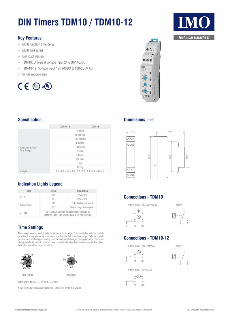
• TDM10: Universal voltage input 24-300V AC/DC
• TDM10-12: Voltage input 12V AC/DC & 180-265V AC
• Single module size
TDM10-12 TDM10
Adjustable Values / Time Range
1 second
10 second
100 second
1 minute
10 minute
1 hour
10 hour
100 hour
1 day
10 day
Multiplier 0.1 - 0.2 - 0.3 - 0.4 - 0.5 - 0.6 - 0.7 - 0.8 - 0.9 - 1
Specification
Technical Datasheet
REF: DIN Timers TD Datasheet 0820Errors and omissions excepted. Subject to change without notice. © 2020 IMO Precision Controls Ltd For more information visit www.imopc.com
LED State Description
On / tON Power On
OFF Power Off
Relay OutputON Output relay energised
OFF Output relay de-energised
M1, M2M1, M2 are used to indicate which function is
currently used. See charts page 3 for more details.
Indication Lights Legend
Time SettingsTime range selector switch selects full scale time range. The t multiplier selector switch provides fine adjustment of time value, t, within the full scale time range. Selector switch positions are latched upon startup to avoid accidental changes during operation. Therefore changing selector switch positions have no effect when the device is operational. The below example shows how to set a t value.
Dimensions (mm)
DIN Timers TDM10
SpecificationTDM10
Adjustable values / Time Range
Multiplier
1 second10 second100 second
1 minute10 minute
1 hour10 hour100 hour
1 day10 day
0.1 - 0.2 - 0.3 - 0.4 - 0.5 - 0.6 - 0.7 - 0.8 - 0.9 - 1
ConnectionsyaleRtupnI rewoP
24..300V AC/DC
Time SettingsTime range selector switch selects full scale time range. The t multiplier selector switch provides fine adjustment of time value, t, within the full scale time range. Selector switch positions are latched upon startup to avoid accidental changes during operation. Therefore changing selector switch positions have no effect when the device is operational. The below example shows how to set a t value.
In the above figure: t=10h x 0.5 = 5 hour
Note: All the pot values are digitilised. Cannot be set to mid values.
Time range t multiplier
Dimensions
Multi-function time delay
Multi-time range
Compact design
Universal voltage input 24~300V AC/DC
Single module size
Indication Lights Legend
LED State Description
ONOFFONOFF
Power ONPower OFF
Output relay energisedOutput relay de-energised
On/t
Relayoutput
M1, M2 are used to indicate which function is currently used, see charts page
3 for more detailsM1, M2
TDTimers 03/17
T
Time Range t Multiplier
In the above figure: t=10h x 0.5 = 5 hour
Note: All the pot values are digitalised. Cannot be set to mid values.
17.50
90.4
0
62.00
45.0
0
68.3
7
Connections - TDM10
RelayPower Input
T U1 U2
24..300V AC/DC
2 3
1
Connections - TDM10-12
Power Input Relay
T U1 U3
180..256V AC
2 3
1
Power Input
T U2 U3
12V AC/DC

DIN Timers TDM10 / TDM10-12Technical Datasheet
REF: DIN Timers TD Datasheet 0820Errors and omissions excepted. Subject to change without notice. © 2020 IMO Precision Controls Ltd For more information visit www.imopc.com
DIN Timer TDM10 continued
Mode functions
A On Delay The output relay is initially de-energised after an adjustable time delay, t.
B Off delay The output relay is intially energised and de-energised after an adjustable time delay, t.
C On-delay with control inputThe output relay is initally de-energised. A contact closure on K input triggers an adjustable time delay, t, which energises the output relay when expired. The output relay stays energised as long as the K input isactive. Delay time, t, is cleared when the contact on K input opens.
D Off delay with control inputThe output relay is initally de-energised and energised when a contact closure on K input is detected.A contact release on K input triggers an adjustable time delay, t, which de-energises the output relay when expired. Reclosure of the contact on K input before the time delay is expired restarts time delay, t, and keeps the output relay energised
E Rising edge triggerred Off delayThe output relay is initially de-energised. A contact closure on K input both energised the output relay and triggers an adjustable time delay, t, which de-energises the output relay when expired. During the time delay, K input is insensitive to state changes and becomes sensitive when time delay, t, expired.
F Falling edge triggerred Off delayThe output relay is initially de-energised. A state change of the contact on K input from closed to open both energises the output relay and triggers an adjustable time delay, t, which de-energises the output relay when expired. During the time delay, K input is insensitive to state changes and becomes sensitive when time delayt, expired.
G Off flasherThe output relay is initially de-energised and energised after an adjustable time delay, t, and stays energisedfor the period, t, and the de-energised. This loop is repeated until the device is powered off.
H On and Off delay with control inputThe output relay is initially de-energised. A contact closure on K input triggers an adjustable time delay, t, whichenergises the output relay when expired. Similarly contact release of K input triggers the time delay, t, which de-energises the output relay when expired. Delay time, t, is cleared when the contact state of K input changes.
I Adjustable pulse output with control inputThe output relay is initially de-energised. A state change on K input both energises the output relay and triggersan adjustable time delay, t, which de-energises the output relay when expired. During the time delay, K input is insensitive to state changes and becomes sensitive when time delay, t, expired.
K On delay with memoryThe output relay is initially de-energised. If K input is open, adjustable time delay, t, counts down and outputrelay energises when t is expired. Any contact closure on K input pauses the count down process, and the process continues when the contact release on K input occurs. A contact release is needed to restart thecycle, after the output relay is energised.
T
T
T
T
T
T
T
www.imopc.comTDTimers 07-13
Mode Functions
A On Delay (M2 LED Flashing)On application of supply voltage, the timer starts. After time t has elapsed, the output Relay energises. Power off reset.
B Off Delay (M1 LED Flashing)On application of supply voltage, the output Relay is energized, and the timer starts. After time t has elapsed, the output Relay de-energises. Power off reset.
C On Delay with Control Input (M1 LED On, M2 LED Flashing)Supply to the unit must be continuous. The output Relay is initially de-energized. Closure of input T starts the timer and the output Relay is energised after time t has elapsed. The Relay remains energized while input T remains closed, opening input T resets and de-energises the output Relay.
D Off Delay with Control Input (M2 LED On, L1 LED Flashing)Supply to the unit must be continuous. Closure of input T energizes the output Relay. opening input T starts the timer. When time t has elapsed the output Relay is de-energized. Reconnection of input T restarts the time delay and the output Relay will remain energized if the time has not elapsed.
E Rising Edge Triggered Off Delay (Asynchronous Flashing of M1 & M2 LEDs)Supply to the unit must be continuous. Closure of input T energizes the output relay and starts the timer, after time t has elapsed the output Relay is de-energized. Changes to the input T will be ignored during the timing period t.
F Falling Edge Triggered Off Delay (Synchronous Flashing of M1 & M2 LEDs)Supply to the unit must be continuous. Pulse signal of input T energizes the output relay and starts the timer, after time t has elapsed the output Relay is de-energized. Changes to the T input will be ignored during the timing period t.
G Off Flasher (Rapid Synchronous Flashing of M1 & M2 LEDs)Application of supply voltage starts the timer with the output Relay initially de-energized, it is energised after the set time t has elapsed then de-energized for time t. The process repeats, until supply is removed.
H On and Off Delay with Control Input (Rapid Asynchronous Flashing of M1 & M2 LEDs)Supply to the unit must be continuous. Closure of input T starts the timer, when time t has elapsed the output Relay energizes, after which on opening of this connection the timing period t restarts and output Relay is de-energized after the set time t has elapsed.
I Adjustable Pulse Output with Control Input (M1 LED Flashing Slowly)Supply to the unit must be continuous. Closure of input T starts the timer and energizes the output Relay, changes to the T input will be ignored during the time t. The Relay is then de-energized after the set time t has elapsed.
K On Delay with Memory (M2 LED Flashing Slowly)Supply to the unit must be continuous. On application of supply voltage, the timer starts. On completion of time t, the output Relay energises. Closure of input T pauses the timer, re opening input T resumes the count. Once set time t has elapsed making and breaking input T restarts the process.
NOTE: Any changes made to mode or time require power down / power up cycle to take effect.
DIN Timers TDAS
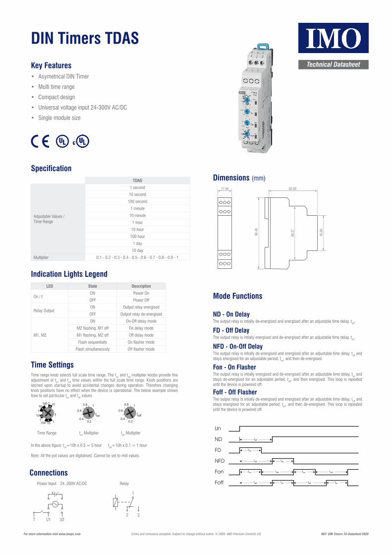
Key Features• Asymetrical DIN Timer
• Multi time range
• Compact design
• Universal voltage input 24-300V AC/DC
• Single module size
TDAS
Adjustable Values / Time Range
1 second
10 second
100 second
1 minute
10 minute
1 hour
10 hour
100 hour
1 day
10 day
Multiplier 0.1 - 0.2 - 0.3 - 0.4 - 0.5 - 0.6 - 0.7 - 0.8 - 0.9 - 1
Specification
Technical Datasheet
REF: DIN Timers TD Datasheet 0820Errors and omissions excepted. Subject to change without notice. © 2020 IMO Precision Controls Ltd For more information visit www.imopc.com
LED State Description
On / tON Power On
OFF Power Off
Relay OutputON Output relay energised
OFF Output relay de-energised
M1, M2
ON On-Off delay mode
M2 flashing, M1 off On delay mode
M1 flashing, M2 off Off delay mode
Flash sequentially On flasher mode
Flash simultaneously Off flasher mode
Indication Lights Legend
Time SettingsTime range knob selects full scale time range. The ton and toff multiplier knobs provide fine adjustment of ton and toff time values within the full scale time range. Knob positions are latched upon startup to avoid accidental changes during operation. Therefore changing knob positions have no effect when the device is operational. The below example shows how to set particular ton and toff values
Dimensions (mm)
Time Range ton Multiplier
In the above figure: ton=10h x 0.5 = 5 hour toff=10h x 0.1 = 1 hour
Note: All the pot values are digitalised. Cannot be set to mid values.
17.50
90.4
0
62.00
45.0
0
68.3
7
ConnectionsRelayPower Input
T U1 U2
24..300V AC/DC
2 3
1
TDASMode functions
Time Settings
Specification
Indication Lights Legend
Dimensions
Connections
24-300V DC
24-300V AC
LED
TDAS
Adjustable values / Time Range
Multiplier
1 second10 second100 second
1 minute10 minute
1 hour10 hour100 hour
1 day10 day
0.1 - 0.2 - 0.3 - 0.4 - 0.5 - 0.6 - 0.7 - 0.8 - 0.9 - 1
On/t
Relay Output
M1, M2
State Description
TDTimers 03/17
toff Multiplier
Mode Functions
ND - On DelayThe output relay is intially de-energised and energised after an adjustable time delay, toff.
FD - Off DelayThe output relay is intially energised and de-energised after an adjustable time delay, ton.
NFD - On-Off DelayThe output relay is intially de-energised and energised after an adjustable time delay. toff and stays energised for an adjustable period, ton, and then de-energised.
Fon - On FlasherThe output relay is intially energised and de-energised after an adjustable time delay, ton and stays de-energised for an adjustable period, toff, and then energised. This loop is repeated until the device is powered off.
Foff - Off FlasherThe output relay is intially de-energised and energised after an adjustable time delay, toff and stays energised for an adjustable period, ton, and then de-energised. This loop is repeated until the device is powered off.
TDASMode functions
Time Settings
Specification
Indication Lights Legend
Dimensions
Connections
24-300V DC
24-300V AC
LED
TDAS
Adjustable values / Time Range
Multiplier
1 second10 second100 second
1 minute10 minute
1 hour10 hour100 hour
1 day10 day
0.1 - 0.2 - 0.3 - 0.4 - 0.5 - 0.6 - 0.7 - 0.8 - 0.9 - 1
On/t
Relay Output
M1, M2
State Description
TDTimers 03/17

DIN Timers TDSD1
Key Features• Star Delta DIN Timer
• Multi time range
• Compact design
• Single module size
Mode Functions
Technical Datasheet
REF: DIN Timers TD Datasheet 0820Errors and omissions excepted. Subject to change without notice. © 2020 IMO Precision Controls Ltd For more information visit www.imopc.com
Dimensions (mm)17.50
90.4
0
62.00
45.0
0
68.3
7
Connections
Power Input 150-500V AC Relay
2 3
1
TDS1 star-delta starter is used for take-off starting method used in electrical motors.When energy applied from U1 and U2 terminals, star contacts will be energised until theend of the adjustable t time. Later, at the end of the adjusted wait time t ∆, delta contactswill be energised until the device powered off.
Y Y
TDS1 star-delta starter is used for take-off starting method used in electrical motors.When energy applied from U1 and U2 terminals, star contacts will be energised until theend of the adjustable t time. Later, at the end of the adjusted wait time t , delta contactswill be energised until the device powered off.
TDSD1Mode Functions
Dimensions
Connections
AC 150-500V
IMOTDSD1
TDTimers 03/17
U1 U2
∆ Relay
∆2 ∆3
∆1
Y
Y
Y Y
U2U1
2Y
3Y
1Y
∆1 ∆2 ∆3
IMOTDSD1
∆3
3Y
start
C1
N
L3
L2
L1
T1
M3~
WV
U
YX
Z
C2
N
∆3
C3
N
3Y
∆Y