diodedco r o coor cotror warning do not … · 12v dc 24v dc rgb zone remote rgb zone receiver ......
TRANSCRIPT

1.877.817.6028www.DiodeLED.com
[email protected] www.DiodeLED.com
INSTALLATION GUIDE
1 OF 4
RGB ZONE COLOR CONTROLLER
®
• Install in accordance with the National Electric Code, and local regulations.
• This product is intended to be installed and serviced by a qualified, licensed electrician.
• DO NOT connect directly to high voltage power. Install with a compatible Class 2 constant voltage LED driver (power supply).
• Only install compatible LED drivers and fixtures. Contact technical support or visit the product page for compatible products.
• This product is rated for indoor installation and is not protected against moisture.
• Proper heat dissipation will prolong the working lifespan of this product. Install in a well-ventilated area free from explosive gases and vapors.
• Ensure applicable wire is installed between driver, fixture, and any controls in between. When choosing wire, factor in voltage drop, amperage rating, and type (in-wall rated, wet location rated, etc.). Inadequate wire installation could overhead wires, and cause a fire.
• Do not modify or disassemble this product beyond instructions or the warranty will be void.
Safety & Warnings
Prior to installation, verify all components are a compatible system. Configure and pre-test your LED system prior to permanent installation to ensure all components are operating correctly. Install in accordance with the NEC and local regulations.
Installation
Quick Specs
Input / Output Voltage 5-24VDC constant voltage
Max Current Load 5A x 4CH Max 20A
Max Output Power 100W/240W/480W (5V/12V/24V)
Ambient Temperature -22° ~ 131°F (-30° ~ 55°C)
Environment Indoor / dry location
Input Voltage 5VDC Built-in Lithium Battery
Transmitting Distance 90 ft.
Control Type Pulse Width Modulation (PWM) 3-channel RGB fixtures
Ambient Temperature † -4° ~ 131°F (-20° ~ 55°C)
Turn OFF High Voltage AC Power at the main breaker. Determine Locations to Install 3 Main Components.Refer to the ‘System Diagrams.’
1
ON
OFF
OFF
OFF
ON
ON
OFF
OFF
ON
ON
2
V+
V-
V+
B
G
R
1) Driver 2) RGB Color Controller
3) Fixture
Ensure applicable wire is installed between driver, fixture, and any controls in between. When choosing wire, factor in voltage drop, amperage rating, and type (in-wall rated, wet location rated, etc.).
DO NOT CONNECT DIRECTLY TO HIGH VOLTAGE POWER!Read all warnings and installation instructions thoroughly.WARNING
WARNING Shock Hazard. May result in serious injury or death.
DO NOT CONNECT TO HIGH VOLTAGE Dry Location Only
12VDC
24VDC
RGB Zone Remote RGB Zone Receiver
For full specifications, see the ‘Specification Sheet’ available at the online product page.
† Do not install product in an environment outside the listed ambient temperature. Ensure adequate airflow and heatsinking is considered when mounting/installing.
DC+
DC-
V+BGR
RF RF
DO NOT PAIR MULTIPLEREMOTES TO A SINGLE RECEIVER.
Zone 1Zone 1
DC+
DC-
V+BGR
DC+
DC-
V+BGR
RF
DO NOT SET MULTIPLE RECEIVERS TO THE SAME ZONE.
IG060914-1.2
# DI-1700 # DI-1701

1.877.817.6028www.DiodeLED.com
[email protected] www.DiodeLED.com
INSTALLATION GUIDE
2 OF 4
RGB ZONE COLOR CONTROLLER
®
Operation
Mount RGB Receiver to Surface. See ‘Wiring Connections’, use applicable screws.
Attach Lighting Load and Driver. Only use copper wiring. Reference ‘Wiring Connections’ located further in guide for visual. Use a mini flathead screwdriver for attaching wires to terminal ports. Terminals fit up to 12AWG solid-core copper wire. Verify a compatible constant voltage driver is installed.
Install Additional Components, Verify Connections, and Turn Main Power ON at Breaker.
3
4
5
ON OFF
OFF
OFF
ONON
OFF
OFF
ONON
If system remains unresponsive or is working improperly, turn OFF main power at breaker and verify all connections. Review the ‘Wiring Connections’ or ‘Troubleshooting’ sections for further details.
Charging the Zone Remote• A flashing red indicator light on the Zone Remote implies a low battery.
• To charge the Zone Remote, connect the included USB 2.0A/Mini-B cable to the remote and to any USB compatible computer or mobile charger with a USB port (not included).
• Press the power button on the Zone Remote and a blue indicator light will flash continuously to indicate charging. Once the indicator light turns green, charging is complete.
Resetting Receiver to Factory Settings• To reset a single receiver, long press the ‘Power’ button on the receiver (you will hear an initial beep). Continue holding for >8 seconds until the
receiver long beeps. The receiver has now been reset to factory settings.
Pairing the Zone Remote with a Zone Receiver. The Zone Remote can control up to 10 different Zone Receivers. Only one remote can be paired to each receiver. To pair the Zone Remote with a Zone Receiver:
• POWER: Turns the Zone Receiver and Zone Remote ON/OFF.
• PAUSE: A quick press of the PAUSE key freezes the current MODE. Holding the PAUSE key on the Zone Remote for 3 seconds will turn the sound on all Zone Receivers ON/OFF.
• MODE: Cycles through 18 pre-programmed MODES. Holding MODE for 3 seconds until a long beep sounds will cycle the MODE to No. 1 of the Mode Description Chart and adjust the SPEED to 5.
• SPEED: Press to cycle through 8 different SPEEDS of any current MODE. Holding SPEED for 3 seconds until a buzzer sounds will adjust the SPEED to 5.
• BRIGHTNESS: Press to cycle through 8 BRIGHTNESS levels of any current MODE or single color. Holding BRIGHTNESS will gradually increase light intensity. A quick double-beep indicates maximum brightness if sound is turned on (see PAUSE key for turning sound ON/OFF).
• COLOR ADJUSTMENT WHEEL: Adjusts static colors. The LED indicator in the center of the COLOR ADJUSTMENT WHEEL displays the current static color selected.
• ZONE CONTROL: Selects a specific zone to control (1-10). To choose all 10 zones press “ * ” twice. To control a selected number of zones in sync press “ *
+ any numeral + * ”. For example, if you would like to control zones 1, 5, & 9 together, press “ * 159 * ”.
• SAVED SCENE: Holding M1 or M2 (Memory 1 or Memory 2) for 3 seconds will save the current static color or MODE to a SAVED SCENE. To indicate a saved scene the zone receiver will long beep and a red indicator light will flash 3 times on the Zone Remote.
6
1. Turn on the Remote and Receiver by pressing the power button on each device.
2. Next, press and hold the power button on the Receiver for 3 seconds until you hear a short beep, and continue to hold. Once the Receiver short beeps immediately hold down a zone number of your choice (1-10) on the Remote. Ensure to continue holding the power button on the Receiver after it beeps, and then simultaneously choose a zone on the Remote.
3. To indicate pairing, the Receiver will long beep and a green indicator light will flash 3 times on the Remote.
See the online product page for video tutorials or contact technical support.
Need Additional Assistance?
IG121014-1.3

1.877.817.6028www.DiodeLED.com
[email protected] www.DiodeLED.com
INSTALLATION GUIDE
3 OF 4
RGB ZONE COLOR CONTROLLER
®
Mode Description Chart Wiring Connections
No. Mode1 3 colors changing
2 7 colors changing
3 White flash
4 7 colors flashing
5 RGB fade in/out
6 Red/Green fade
7 Red/blue fade
8 Green/blue fade
9 Red/yellow fade
10 Green/cyan fade
11 Blue/purple fade
12 Green/yellow fade
13 Blue/cyan fade
14 Red/purple fade
15 Blue/white fade
16 Yellow/purple/cyan fade
17 RGB
18 Full color fade
DO NOT connect directly to 120VAC. Install in accordance with the NEC, and local regulations.
DC+DC-
V+BGR
RF
Input from 12-24V LED Driver
To Low VoltageLED Load
Zone
Rem
ote
Zone
Rec
eive
r
Troubleshooting
Fixture does not illuminate
• See ‘System Diagram’ and installation guides of all components. Ensure the system is wired correctly. • Verify polarities are correct. • Ensure a compatible constant voltage dimmable fixture is installed.• Ensure a compatible constant voltage driver is installed. • Ensure the driver and fixture have the same voltage specifications (12V & 12V, or 24V & 24V).
Fixture does not dim • Ensure a compatible constant voltage dimmable fixture is installed.• Ensure desired zone is selected before changing brightness.
Fixture is flashing or flickering• Verify a compatible constant voltage driver is installed. • Ensure a compatible constant voltage dimmable fixture is installed.• Ensure all connections are properly secured.
Fixture is slowly flashing • Ensure driver is not overloaded. An overloaded driver will cause the internal auto-reset of the driver to trip repeatedly.
Correct colors are not illuminating • Verify the correct leads are connected to the correct terminals on the receiver. • Ensure potential leads at opposing end of fixture are not crossed.
Unable to pair remote with receiver• Ensure the remote is fully charged.• Read the installation instructions on page 2 thoroughly.• Reset the receiver(s) to factory settings.
Receivers unintentionally sync together • If receivers are not paired to a remote, they may unintentionally sync together. To de-sync receivers see ‘Resetting Receivers to Factory Settings’ on page 2.
Prior to troubleshooting, ensure a compatible system is installed. Verify compatible fixtures, drivers, controls and additional components were specified correctly.
IG121014-1.3
1.877.817.6028www.DiodeLED.com
[email protected] www.DiodeLED.com
INSTALLATION GUIDE
4 OF 4
RGB ZONE COLOR CONTROLLER
®
Additional Resources
QUESTIONS? Visit www.DiodeLED.com or contact Customer Support at [email protected] or 1.877.817.6028 Monday through Friday, 7:00am - 5:00pm PST.
IG121014-1.3
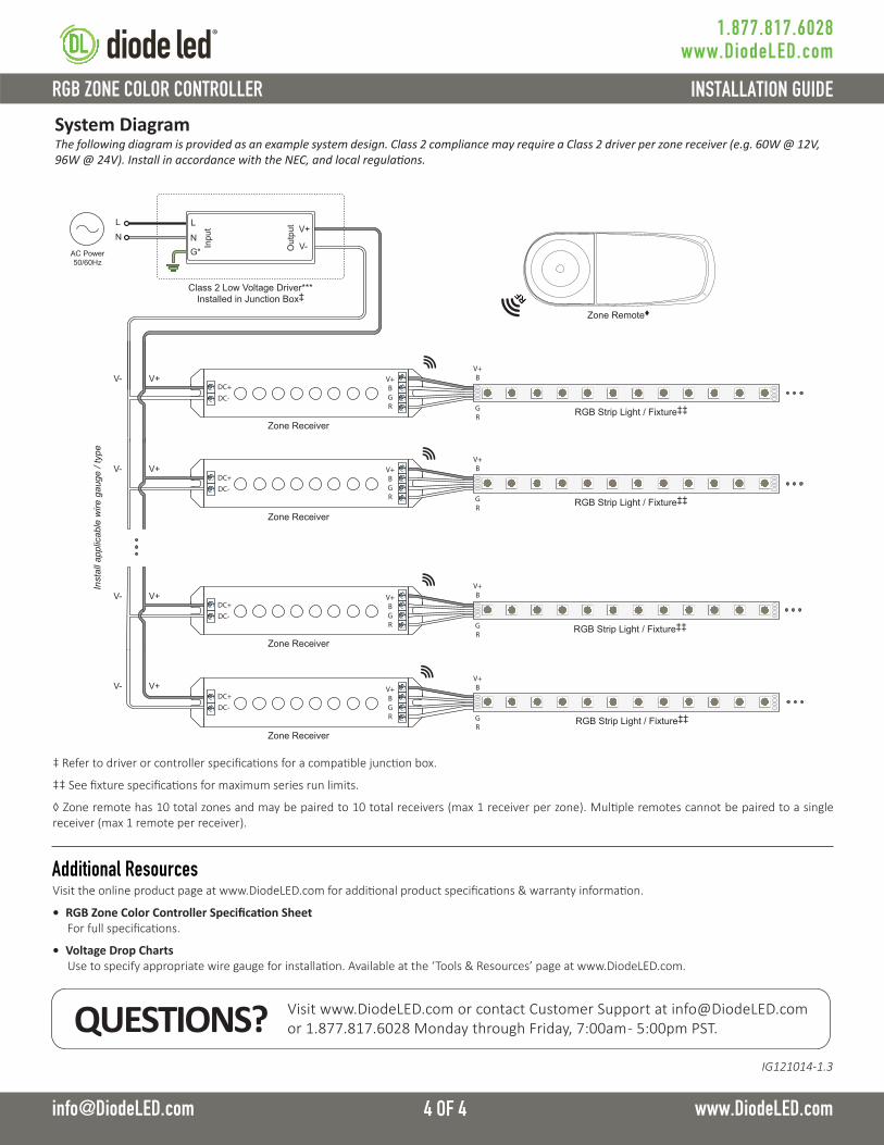
System DiagramThe following diagram is provided as an example system design. Class 2 compliance may require a Class 2 driver per zone receiver (e.g. 60W @ 12V, 96W @ 24V). Install in accordance with the NEC, and local regulations.
Inst
all a
pplic
able
wire
gau
ge /
type
AC Power50/60Hz
L
N
Class 2 Low Voltage Driver*** Installed in Junction Box‡
G*N
L
Inpu
t
Out
put V+
V-
V- V+
V- V+
V- V+
RGB Strip Light / Fixture‡‡
RGB Strip Light / Fixture‡‡
RGB Strip Light / Fixture‡‡
RGB Strip Light / Fixture‡‡
V- V+
DC+DC-
V+BGR
DC+DC-
V+BGR
DC+DC-
V+BGR
DC+DC-
V+BGR
Zone Receiver
Zone Remote♦
RF
Zone Receiver
Zone Receiver
Zone Receiver
V+B
GR
V+B
GR
V+B
GR
V+B
GR
‡ Refer to driver or controller specifications for a compatible junction box.
‡‡ See fixture specifications for maximum series run limits.
◊ Zone remote has 10 total zones and may be paired to 10 total receivers (max 1 receiver per zone). Multiple remotes cannot be paired to a single receiver (max 1 remote per receiver).
Visit the online product page at www.DiodeLED.com for additional product specifications & warranty information.
• RGB Zone Color Controller Specification Sheet For full specifications.
• Voltage Drop Charts Use to specify appropriate wire gauge for installation. Available at the ‘Tools & Resources’ page at www.DiodeLED.com.