directional seated valves - hawe · pdf filedirectional seated valves directly actuated,...
TRANSCRIPT

Directional seated valvesDirectly actuated, leakagefree for hydraulic systemsFor the assembly on connection sub-plates
D 7300Directional seated valves
May 2007-02
HAWE HYDRAULIK SESTREITFELDSTR. 25 • 81673 MÜNCHEN
2.2
© 1980 by HAWE Hydraulik
Valve for sub-plate mounting Section 3 Pressure pmax 350...500 (700) barValve with individual connection sub-plate Section 5 Flow Qmax 6...120 l/minDirectional valve bank D 7302
1. General informationDirectional control valves are generally used for the direct, leakage free control of consumers and as pilot valves for hydraulicallyactuated valves (depending on the flow pattern). They are designed as spring returned ball seated valves. The valve elements areforced into their respective switching position against the spring force and fluid pressure by various actuation elements via an elbow lever acting on a pin. A strainer insert in the inlet port prevents the entry of coarse contamination.The fluid ducts end as holes with O-ring seals at the ground, bottom surface of the valve body. Pipes may be connected either via customer furnished connection blocks or sub-plates (for individual valves with sub-plates see sect. 5 or for valve banks see D 7302).These valves do not show any leakage in blocked switching position. Reliable shifting is ensured, as these valves are designed asball seated valves where there is no seizing or sticking in working position under full pressure. The leverage between actuation andvalve element ensures low actuation forces and smooth shifting. To avoid interaction, most of these directional control valves are available with check valve inserts and return pressure stops or orifice inserts to limit the inflow of oil.Individual valves with sub-plate, enabling direct pipe connection, may be equipped with a by-pass check valve, a pressure limitingvalve, or a rectifier circuit by means of check valves.
2. Overview(For complete type overview, see sect. 8)
Individual valve for manifold mounting
Solenoid actuated2/2-way directionalseated valve, size 1,free flow whendeenergized
Actuation modesFor detailed data. see section 4++.(Max. pressure rating depending on flow pattern and size. see sect. 3.1 table 2)
Solenoid actuated 3/2-waydirectional seated valve,size 2 with check valve in-sert in port P
Tapped ports in the connection sub-plate, G 3/8
Individual valve with connection sub-plate for direct pipe connection
e.g. GS 2-1-G 24 e.g. GZ 3-2R-3/8-G 24
Code letter
Picture andsymbol
Solenoid
G WG
Pressure hydraulic pneumatic
H P
Mechanical roller pin
K T
Manual feeler turn-knob
F D

D 7300 page 2
Order example:
Solenoid actuation (acc. to sect. 4.1)G = DCWG = AC
For actuation modes H, P, K, T, F, D, see sect. 2 and 4.2 ++
3. Individual valves, manifold mounting 3.1 Valve
(For individual valves with connection sub-platefor pipe connection, see sect. 5)
GR 2 - 3 R - G 24
Table 1: Flow pattern
Coding
Detailedsymbols(must becompletedby actuationsymbol)
Simplifiedflow patternsymbol
2/2-way valve
R2 3) S2 3)
3/2-way valve
3 3) Z3 3)
3/3-way valve
21
4/3-way valve
22 1)
4/2-way valve
4 2) 3) Z4 2) 3)
1) Not available for size 4! Note the arrangement of solenoids a and bin relation to the ports A and B, see dim. drawings sect. 3.3.3
2) Only available for size 13) Size 1 also available as explosion-proof version, see sect. 4.1.3
Table 2: Size, main data
Coding
Max. flow approx. lpm
Directional valves (... -way)
Type G..a. WG..
Type H..
Type P..
Type K..
Type T..
Type F..
Type D..
0
6
2/2; 3/2 3/3 4/3
500 350
500 500
--- ---
--- ---
--- ---
--- ---
500 --- ---
1
12
2/2; 3/2; 3/3; 4/2 4/3
500 4) 350
700 500
700 400
700 400
700 400
700 400
700 400
2
25
2/2; 3/2; 3/3 4/3
500 4) 350
500 500
500 400
500 400
500 400
500 400
500 ---
3
65
2/2; 3/2; 3/3 4/3
400 350
400 400
400 350
400 350
--- ---
400 350
--- ---
4
120
2/2; 3/2; 3/3
350
---
---
---
---
---
---
Pres-surepmax
(bar)
4) For max. pressure during shifting, see sect. 4.1
Table 3: Additional elements to influence shifting operations,inserted in port P or R (can be retrofitted).
Additional element
solenoid voltage (standard)G 24 = 24 V DC; WG 230 = 230 V ACsee sect. 4.1Additional element (see table 3)
Size and main data (see table 2)
Note
Not avail. for 3/3- and 4/3-way directional spool valves type ...21 and ...22The check valve prevents an uncontrolled impact or reflow R→P or A→P,e.g. if the inlet pressure at P drops below the consumer pressure at A (dur-ing idle position or actuation of another consumer with a lower pressure re-quirement) when several valves are connected in parallel. A pressure reduc-tion is prevented during such switching operations.
Not available for 4/3-way valves type ...22 !The orifice serves to limit the flow (see |p-Q curves) and should be installedif flow rates higher than Qmax (table 2) can occur while switching from P→A(R): Hydraulic accumulators on the pump side P or in the case of hydr. servo op-eration of directional spool valves with control oil supply from the high flowmain gallery.
Only available for 3/2-way valves types ..3-.. or ..Z3-.. .Check valves may be installed in the reflow ports R of 3/2-way valves size0and1. With parallel shifting of several valves, they prevent pressure surgesfrom migrating via the common reflow gallery into non-operated, easily mov-ing and unloaded consumers if there is a connection A→R, thus preventinguncontrolled extension movements. Such pressure surges can be caused byshifting operations. These check valves are not intended for blocking off hy-draulic oil, which depending on the combination of switching operations ofother valves, can arise at port R.
Coding and symbol
R
B
S
for Typesize
all
all
0 7332 000a
1 7332 000b
Insert check valves type ERacc. to D 7325 e.g. type ER 01 for valvessize 0
Insert orificestype EBacc. toD 6465
Returnpressurestop
A combination with check valve ororifice in port P is possible e.g. G 3-1 BS-G 24,
GZ 3-1 RS-G 24
Installation illustration
Check valveor orifice installed inport P
Returnpressurestop installed inport R
Mechanicalactuation
Pressure actuation
Solenoid actuation
Manual actuation
size 0 = EB 0-0,61 = EB 1-0,82 = EB 2-1,23 = EB 3-2,54 = EB 4-4,0
D 7300 page 3
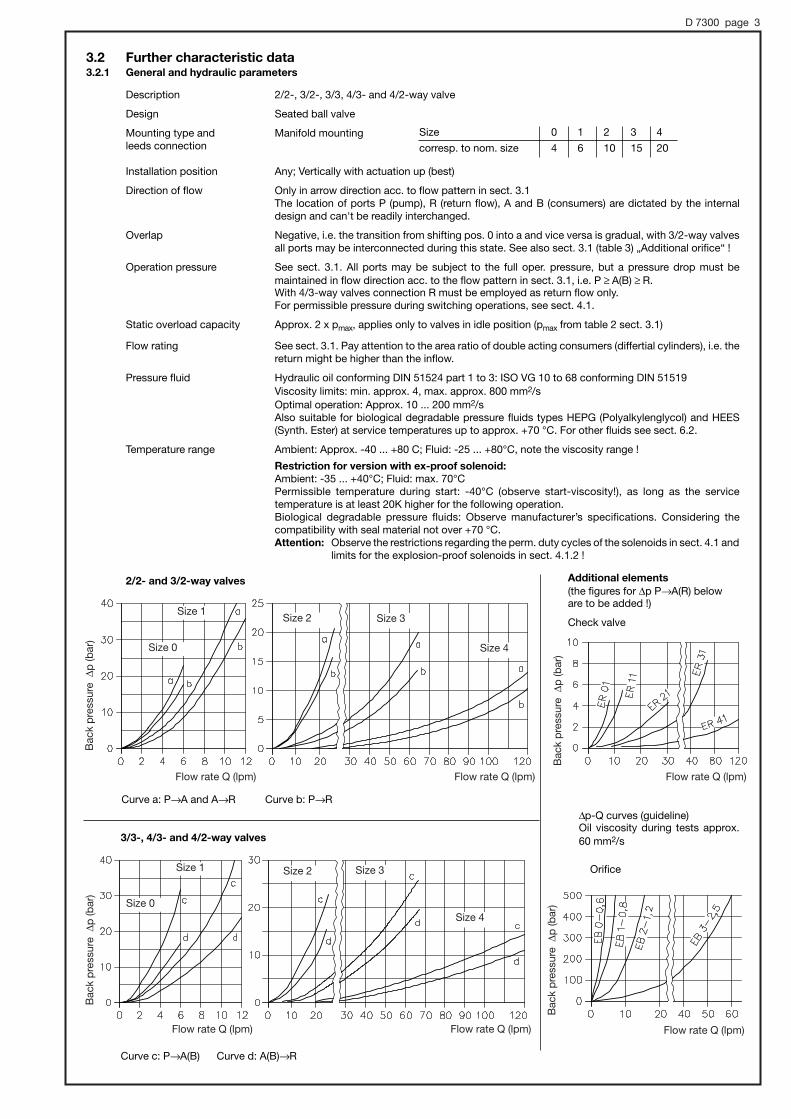
3.2 Further characteristic data3.2.1 General and hydraulic parameters
Description 2/2-, 3/2-, 3/3, 4/3- and 4/2-way valve
Design Seated ball valve
Mounting type and Manifold mountingleeds connection
Installation position Any; Vertically with actuation up (best)
Direction of flow Only in arrow direction acc. to flow pattern in sect. 3.1The location of ports P (pump), R (return flow), A and B (consumers) are dictated by the internal design and can't be readily interchanged.
Overlap Negative, i.e. the transition from shifting pos. 0 into a and vice versa is gradual, with 3/2-way valvesall ports may be interconnected during this state. See also sect. 3.1 (table 3) „Additional orifice“ !
Operation pressure See sect. 3.1. All ports may be subject to the full oper. pressure, but a pressure drop must be maintained in flow direction acc. to the flow pattern in sect. 3.1, i.e. P ≥ A(B) ≥ R.With 4/3-way valves connection R must be employed as return flow only.For permissible pressure during switching operations, see sect. 4.1.
Static overload capacity Approx. 2 x pmax, applies only to valves in idle position (pmax from table 2 sect. 3.1)
Flow rating See sect. 3.1. Pay attention to the area ratio of double acting consumers (differtial cylinders), i.e. thereturn might be higher than the inflow.
Pressure fluid Hydraulic oil conforming DIN 51524 part 1 to 3: ISO VG 10 to 68 conforming DIN 51519Viscosity limits: min. approx. 4, max. approx. 800 mm2/sOptimal operation: Approx. 10 ... 200 mm2/sAlso suitable for biological degradable pressure fluids types HEPG (Polyalkylenglycol) and HEES(Synth. Ester) at service temperatures up to approx. +70 °C. For other fluids see sect. 6.2.
Temperature range Ambient: Approx. -40 ... +80 C; Fluid: -25 ... +80°C, note the viscosity range !
Restriction for version with ex-proof solenoid:Ambient: -35 ... +40°C; Fluid: max. 70°CPermissible temperature during start: -40°C (observe start-viscosity!), as long as the service temperature is at least 20K higher for the following operation.Biological degradable pressure fluids: Observe manufacturer’s specifications. Considering the compatibility with seal material not over +70 °C.Attention: Observe the restrictions regarding the perm. duty cycles of the solenoids in sect. 4.1 and
limits for the explosion-proof solenoids in sect. 4.1.2 !
2/2- and 3/2-way valves Additional elements(the figures for |p P→A(R) beloware to be added !)
Check valve
Orifice
3/3-, 4/3- and 4/2-way valves
Curve c: P→A(B) Curve d: A(B)→R
Curve a: P→A and A→R Curve b: P→R
Size 1
Size 0
Size 2 Size 3
Size 4
Size 1
Size 0
Size 2 Size 3
Size 4
Bac
kp
ress
ure|p
(bar
)B
ack
pre
ssur
e|p
(bar
)
Bac
kp
ress
ure|p
(bar
)B
ack
pre
ssur
e|p
(bar
)
Flow rate Q (lpm) Flow rate Q (lpm) Flow rate Q (lpm)
Flow rate Q (lpm)Flow rate Q (lpm)Flow rate Q (lpm)
Size 0 1 2 3 4
corresp. to nom. size 4 6 10 15 20
|p-Q curves (guideline)Oil viscosity during tests approx.60 mm2/s
D 7300 page 4
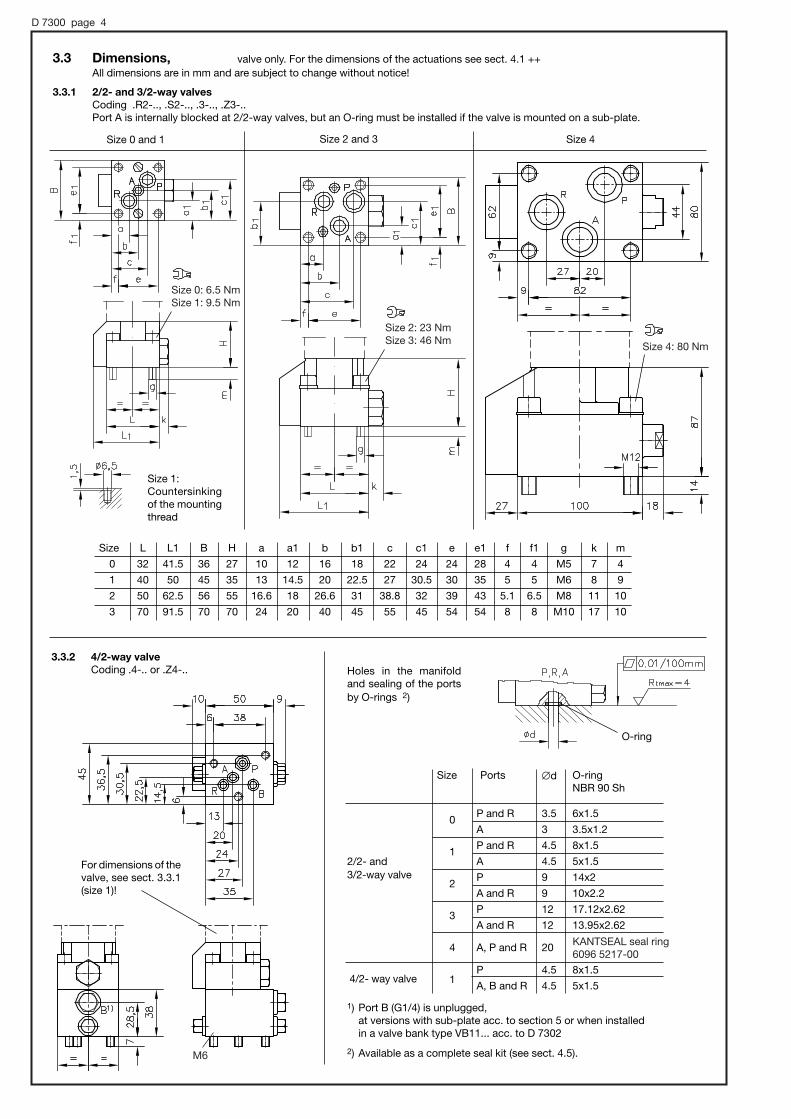
3.3.2 4/2-way valveCoding .4-.. or .Z4-.. Holes in the manifold
and sealing of the portsby O-rings 2)
3.3 Dimensions,All dimensions are in mm and are subject to change without notice!
3.3.1 2/2- and 3/2-way valvesCoding .R2-.., .S2-.., .3-.., .Z3-..Port A is internally blocked at 2/2-way valves, but an O-ring must be installed if the valve is mounted on a sub-plate.
Size 0 and 1 Size 2 and 3 Size 4
valve only. For the dimensions of the actuations see sect. 4.1 ++
1) Port B (G1/4) is unplugged, at versions with sub-plate acc. to section 5 or when installed in a valve bank type VB11... acc. to D 7302
2) Available as a complete seal kit (see sect. 4.5).
Size 1:Countersinkingof the mountingthread
2/2- and3/2-way valve
4/2- way valve
Size
0
1
2
3
4
1
Ports
P and R
A
P and R
A
P
A and R
P
A and R
A, P and R
P
A, B and R
#d
3.5
3
4.5
4.5
9
9
12
12
20
4.5
4.5
O-ringNBR 90 Sh
6x1.5
3.5x1.2
8x1.5
5x1.5
14x2
10x2.2
17.12x2.62
13.95x2.62
8x1.5
5x1.5
Size
0
1
2
3
L
32
40
50
70
L1
41.5
50
62.5
91.5
B
36
45
56
70
H
27
35
55
70
a
10
13
16.6
24
a1
12
14.5
18
20
b
16
20
26.6
40
b1
18
22.5
31
45
c
22
27
38.8
55
c1
24
30.5
32
45
e
24
30
39
54
e1
28
35
43
54
f
4
5
5.1
8
f1
4
5
6.5
8
g
M5
M6
M8
M10
k
7
8
11
17
m
4
9
10
10
O-ring
For dimensions of thevalve, see sect. 3.3.1(size 1)!
M6
KANTSEAL seal ring6096 5217-00
Size 0: 6.5 NmSize 1: 9.5 Nm
Size 2: 23 NmSize 3: 46 Nm Size 4: 80 Nm

D 7300 page 5
Ports Size 0 Size 1 Size 2 Size 3
Ø d P, R, A a. B 3.5 4.5 9 12
P 6x1.5 8x1.5 14x2 17.12x2.62
R, A and B 6x1.5 5x1.5 10x2.2 13.95x2.62
Holes in the manifold and sealing of the ports by O-rings 1)
Size
0 1 2 3
L 75 92 116 144
B 32 40 50 70
H 31 40 59 70
a 4 5 5.5 8
b 24 30 39 54
c 23 28 39 55
e 11 13 17 22
f 27 35 45 55
g M5 M6 M8 M10
h 4.5 9 10 10
i 19 24 30 38
l 66 82 103 128
m 7 8 11 17
n 11 13 17 23
o 38 45 53 64
Size0 1 2 3 4
L 75 92 116 144 162
B 32 40 50 70 100
H 27 35 55 70 101
a 4 5 5.5 8 9
b 24 30 39 54 82
c 23 28 39 55 74
e 11 13 20 24 27
f 16 27 26 26 41
g M5 M6 M8 M10 M12
h 3.5 9 10 10 16
i 19 20 26 20 25
k 13 15 22 20 25
l 66 82 103 128 144
m 7 8 11 17 18
n 10 10 13 22 26
o 38 45 53 72 82
3.3.3 3/3- and 4/3-way valves
3/3-way valve
Coding .21-..
4/3-way valve
Coding .22-..
O-ring
1) Available as a complete seal kit (see sect. 4.5).
P, R, A and B
Attention: Both return ports R have to beconnected, as there is no internalconnection.

D 7300 page 6
With load cycles ≤ 10% EDAmbient temp. ≤ 40°C (not 4/3-way valves type ...22)
4. Actuation modes4.1 Solenoid actuation (standard)
The solenoids are built and checked conforming to VDE 0580.The standard solenoids are designed for the following voltage: 24V DC (type G..) or 230V AC 50 and 60 Hz (type WG..) acc. to sect. 3.1. It is not required to add these voltages to the order coding. Special voltages have to be specified in uncoded text or to beadded to the order coding. See order examples in sect. 3.1 and "Special voltage" in sect. 4.1.2 .
Valve type acc. to sect. 3.1 Size 0 Size 1 Size 2 Size 3 Size 4
G... WG... 1) G... WG... 1) G... WG... G... WG... G... WG...
Nom. voltage UN 12 V DC, 24 V DC, 110 V DC, 230 V AC see also sect. 4.1.2
Nom. current IN 2) (A) 0.67 0.08 0.83 0.1 1.1 0.13 2.1 0.26 3.6 0.44
Nom. power PN2) (W) 16 16 20 20 26 26 50 50 86 86
on (ms) 40 80 100 100 140 140 175 175 150 150
off (ms) 40 100 50 125 55 150 65 200 100 4) 350 4)
Switchings per hour / h Approx. 2000 (G.. and WG.. all sizes); approx. evenly distributed
Protection mode IP 54 acc. to IEC 60529 (readily assembled), IP 67 acc. to IEC 60529 for explosion-proof version
Isolationsklasse F H
Cut-off energy (Ws) 0.16 0.16 0.24 0.24 0.38 0.38 1.59 1.59 3.4 3.4
Guideline for max. value + approx. 10% according to tests with nom. voltage and 20°C
; ? < > 1) = > = > = >
Plug MSD 2 3)
Plug MSD 1 3)
Plug conf. EN 175 301-803 A, e.g. MSD 3-309 3)Adapter + Socket AMSD 1-MSD 3 + MSD 4-209 P10 3)Adapter + Socket AMSD 2-MSD 3 WG + MSD 3-309 3)
These connectors 3) are part of the order coding as standard. For other connectors e.g. with clamp diode,economy circuit or LED's see D 7163.
The solenoid valves are suitable for normal outdoor use, if the solenoids are installed vertcall (indicated byprevious experience).
100% ED (stamped on the solenoid), however observe operating duty cycle !Rel. duty cycle
Permissible operation conditions for outdoor use
Connection scheme of the plugs
Plug conf. EN 175 301-803 A
Adapters for size 0 and 1, see sect. 4.1.1
The curves do apply to stand-alone,individual valves only! If the valves areinstalled in a cabinet, it should be al-ways equipped with louvers! In case ofbank arrangement and ambient tem-peratures above 40°C the layoutshould be designed in such a way thatadjoining solenoids are not energizedover prolonged periods.
Increased switchable pressure (other than listed insect. 3.1) for size 1, 2 and 4
5) Attention: The storage capability of high pressure consumers has tobe taken into consideration. Pressure surges during decharging, whichmight harm internal functional parts of the valve or fatigue fracture ofother hydraulic components of the application can be prevented by installing orifices (see sect. 3.1) upstream.
1) Only with adapter, see sect. 4.1.1.2) The electrical data for solenoids G and WG are only a guide-
line (max) and may vary depending on manufacturer.3) Co. K + B GmbH, D-84056 Rottenburg a.d.L.; This type of
plug must be specified, when placing a separate orders.4) Possibly increased tolerance, above 250 bar.
Switching time (guideline)
Type WG...
Type G...
;<=
>
?
Rel. duty cycle duringoperation
Am
bie
ntte
mp
erat
ure}
U(°
C)
Rel. duty cycle
t EDrtTein= ⋅100(% )
Rel. duty cycle (%ED) Continuous operation
Type
G... a. WG..
pmax
(bar)
700
Qmax5)
(lpm)
8
Valves size 1
pmax
(bar)
700
Qmax5)
(lpm)
12
Valves size 2
pmax
(bar)
400
Qmax5)
(lpm)
60
Valves size 4type GR 2-4-G..
Version for size 0 to 3
Version for size 4
(Cycle time)
Time

D 7300 page 7
4.1.1 Plugs for valves size 0 and size 1The standard version comes with a plug (see dimensional drawing and connection scheme)
Order example: GR 2-1
Solenoid voltage 24V DCPlug type
4.1.2 Solenoid voltage Attention: It is important to specify the voltage !
1) Notes for proper selection:DC:The order specification (solenoid)
should be identical with the one ofthe power supply (DC). If the supplyvoltage is lower it will reduce theforce of the solenoid, if it is higherthe solenoid will be heated up un-permissibly (tolerance ± 5-10%).
AC:The order specification should beidentical with the one of the powersupply (50/60 Hz AC). The voltage ofthe solenoid is approx. 0.9 UAC-2 Vdue to the corresponding bridgerectifier. The table identifies the so-lenoids utilized in such cases (e.g.for 110 V AC 50 Hz; solenoid with UN = 98 V DC)
The indicated nominal power ratings are ap-proximate reference values, which may dif-fer insignificantly depending on the voltageand the manufacturer of the solenoid. Thecurrent rating in cold state is I20 = PN / UN
(see examples)
Order specification Size 0 Size 1 Size 2 Size 3 Size 4
DC 1) AC 1)(& UN [V]) 50/60 Hz (16 W) (20 W) (26 W) (50 W) (86 W)
G 12 x x x x x
G 12ex x (23 W)
G 24 WG...-WG 24 x x x x x
G 24ex x (23 W)
G 36 WG...-WG 42 x x
G 42 WG...-WG 48 x x x
G 48 x x x x
G 80 x x x x
G 80ex x (23 W)
G 98 WG...-WG 110 x x x x x
G 110 x x x x
G 110ex x (23 W)
G 125 x x x
G 185 WG...-WG 200 x x x (180V DC) x
G 205 WG...-WG 230 x x x x x
G 220 x x x
-A 24
Coding
Note
Socket Size 0
Size 1
MSD 2
MSD 1
MSD 2-MSD 3WG+ MSD 3-309MSD 1-MSD 3+ MSD 4-209 P10
MSD 2-MSD 3
MSD 1-MSD 3
MSD 2-MSD 3+ MSD 3-309MSD 1-MSD 3+ MSD 3-309
Central plugs (serie)
Valve with adapter and bridgerectifier (socket)The bridge rectifier is incorpo-rated in the adapter for size 0
Valve with adapter forplugs shape A DIN EN 175301-803is customer furnished
Valve with adapterand, plug shape ADIN EN 175301-803
G WG A N
(Nominal power PN)
Electrical data for explosion-proof solenoids
Letter of conformity TÜV-A-03 ATEX 0017 XCoding II 2 GD T135°C IP67 EEx d IIB T4Duty cycle 100% EDProtection class IP 67 (IEC 60529)Nom. voltage UN 24 V DCPower, hot PN 23 W
Note:Only 40 % ED are permissible if the valvesare neighboring, it is additionally recom-mended that neighboring valves are not actuated simultaneously.
PE 1 2 Housing
Restrictions for use:Temperature Ambient: max. +40°C
Fluid: max. +70°CRequired external fuse (conf. DIN IEC 127) IN < 1.6 A-mediumSurface protection Protect against direct sun ligth
see also restriions at “Temperature”)Electrical connection 3x0.5 mm2
Cable length 3 m, Option 10 mObserve the operation manuals B 03/2004 and B ATEX!Electrical lay-out and testing conforming EN 50014, VDE 0170/0171 T1 and T9.
Explosion-proof solenoidsConnection scheme of the plugs
GR 2-2 - G 24 (I20 = 0.54 A)G 3-0R - A 110 (I20 = 0.15 A)WGZ 4-1 - W 200 (I20 = 0.11 A)
Examples:
Directional seated valveacc. to section 3.1
Attention:- Flow pattern 21 and 22 not available
with explosion-proof solenoids- Protect the complete valve against
direct sun light

D 7300 page 8
4.1.3 Unit dimensions
All dimensions are in mm and are subject to change without notice!
1) It is not possible to install the plug in any position if thevalve is part of a valve bank (see D 7302)
2) Either in upward or downward valve bank (see D 7302)3) This dimension is depending on the manufacturer and
may be up to 40 mm more DIN 436504) The bridge rectifier is incorporated in the adapter with
type WG.. size 0 and with size 1 it is part of the plug
Size D Hmax hmax a2 50 71.5 26 303 62 92 27 46
May be installed rotated by 90° 2)
May be installed rotated by 90° 2)
May be installed rotated by 22.5° 1)
Suited forleeds Ø6
Plug may be installed rotated by 180°
Adapter for plugs DIN (ISO 4400) 4)
Adapter plug acc. to sect. 4.1.1,for dimension see size 4
Adapter may be in-stalled rotated by 180°
Size 0 Size 1 Size 2 and 3 Size 4
For di-mensionssee size 4
Size 0 and 1
Push the emergency actua-tion pin inward by means ofa screw driver or similar, if required
Press the actuation pin hid-den under the rubber cap.
Size
Max. actuation force (N)
Cross sectional drawing
0 1 4 2 3
35 80 450 150 250
Manual emergency operation
The manual emergency actuation may be put outof function by blocking thetapped hole by means of ascrew M 3x5 DIN 92
Note
Size 1 with explosion-proof solenoids
Twist stop
Manual emergency
app
rox.
24
app
rox.
34

D 7300 page 9
4.2 Hydraulic and pneumatic actuation
The actuation element is a single acting piston with spring return.The valve will remain in its working position a as long as the control pressure prevails. It will return automatically in its idle position 0 if the control pressure is relieved.The piston is sealed and operates without any leakage.
Hydraulically(Size 0 ... 3)
Oil
H...
Pneumatically(Size 1, 2, 3)
Compressed air, filtered and oiled
P...
Actuation
Control medium
Coding
Size 0 1 2 3 1 2 3
Control pressure (bar) max 500 700 500 400 15
min 16 12 9 9 4 2.5 2.5
Control volume (cm3) 0.2 0.4 0.7 6.1 1 2.5 7
D 32 39 49 60 39 49 60
H 44 36 52 77 36 39 52
a/f 27 27 32 41 --- --- ---
Temperature (ambient and control medium) -40 to + 80°C -20 to + 70°C
a/f
Size 1 2 3 1 2
Switching force range s (N) 25 to 28 42 to 47 55 to 80 51 to 57 95 to 120
Start of function (H + h) 38.5 46.5 76 --- ---
Function path h 10.5 15.5 30 4 5
Switching position range s 3 4 6 --- ---
D 39 49 60 39 49
d 25 25 35 18 22
H 28 31 46 20.5 25.5
H1 --- --- --- 16.5 20.5
a 42 41 62.5 --- ---
b 21 21 26 --- ---
c 12 12 15 --- ---
Actuation mode
Code letter
Dimensional drawing
Roller lever (Size 1, 2, 3) Feeler pin (Size 1 and 2)
K... T...
Do not use as a stop!
Do not use as a stop!
Roller lever switching curve operation direction
dea
dm
otio
n
4.3 Mechanical actuationThe actuation element is a pin (tracer) with spring return, which may be used either directly for vertical directions of operation or viaa roller lever for lateral directions. The valve is in working position a if the actuation element is forced into the hatched area of thelever path.
All dimensions are in mm and aresubject to change without notice!
±0.5
±0.5
±0.5
±0.5
±0.5
±0.5
±0.5
±0.5
±0.5
Switch-ing path(mm)
1) conformingDIN ISO 228/1(BSPP)
All dimensions are in mm and aresubject to change without notice!

D 7300 page 10
4.4 Manual actuation
Feeler lever coding F: The actuation element is a feeler lever which acts on a spring loaded pin. Switching position a is retained as long as the feeler lever is pressed down within the hatched area.v
Turn knob coding D: This actuation element is with detent. Switching position a or 0 alternate as the knob is turned by 90°. The direction of rotation is arbitrary.
Actuation mode
Code letter
Dimensional drawing
Feeler lever (size 1, 2, 3) Turn knob (size 0, 1, 2)
F... D...
Size 1 2 3 0 1 2
Actuation force in the range s (N) 25 to 28 42 to 47 55 to 80 --- --- ---
Switching torque (Ncm) --- --- --- 45 63 98
Actuation travel (mm) hmax 20.5 23.5 45 --- --- ---
s 3.5 4 10 3.5 3.5 5
D 39 49 60 --- --- ---
H 37 43 70 38 40 47
B 34.5 32 56.5 43 43 52
Not to usedas a stop !
Switch-ingposition
4.5 Seal kitsFlowpattern
..R2
..S2
..3
..Z3
..4
..Z4
..21
..22
Size
0
1
2
3
4
0
1
2
3
4
0
1
2
3
G, WG, K, T, F and D
1 x DS 7300-01
1 x DS 7300-11
1 x DS 7300-2N
1 x DS 7300-31
1 x DS 7300-41
1 x DS 7300-02
1 x DS 7300-12
1 x DS 7300-21N
1 x DS 7300-32
1 x DS 7300-42
1 x DS 7300-02
1 x DS 7300-12
1 x DS 7300-22
1 x DS 7300-33
H and P
1 x DS 7300-011 x DS 7300-03
1 x DS 7300-111 x DS 7300-13
1 x DS 7300-2N1 x DS 7300-23
1 x DS 7300-311 x DS 7300-34
1 x DS 7300-022 x DS 7300-03
1 x DS 7300-122 x DS 7300-13
1 x DS 7300-21N2 x DS 7300-23
1 x DS 7300-322 x DS 7300-34
1 x DS 7300-022 x DS 7300-03
1 x DS 7300-122 x DS 7300-13
1 x DS 7300-222 x DS 7300-23
1 x DS 7300-332 x DS 7300-34
Seal kit for actuation
These seal kits contain the O-ringslisted in sect. 3.3 and additional partsand seals.For more detailed information, seespare parts lists E 7300-0, E 7300-1,E 7300-2, E 7300-3 and E 7300-4.
All dimensions are in mmand are subject tochange without notice!

D 7300 page 11
5. Individual valve with connection sub-plateAll ports of the 2/2-, 3/2-, 3/3- and 4/3-way directional seated valves acc. to section 3 are designed as holes with O-ring sealing atthe ground bottom of the valve body. These valves have to be completed with sub-plates or customer furnished manifolds to enable pipe connection.
5.1 Available versions, main data
Order example: GR 2-2 - 1/2S 220- G 12 -
Valve codingacc. to sect. 3
Desired pressure setting in bar(Pressure range depending on spring, see <)
Suited for connection in series and in parallel, if the perm. pressure stated in section 3.2. "Operation pressure" for P,A, B and R are not exceeded.
The rectifier circuit by means of check valves enables both flow directions for the 2/2-way valves. Therefore the portcodings P and R are not stamped on the sub-plate.
1) For male pipe fittings with journals shape B DIN 3852 page 2. 2) Not available for flow pattern 4 and Z4 (table 1)
Port R may be used only for unpressurized return flow to ensure proper function of the pressure reducing valve. Paral-lel connection of additional valves is only permissible with sub-plates acc. to ; but not with sub-plates acc. to <
A by-pass check valve (RK 3 acc. to D 7445) is required to enable flow R → P. Pressure surges (decompression) inflow direction R → P should be avoided ! For pressure rating of R, see sect. 3.2.
Version with G 1 is not available
The pressure specification in the order coding determines the pressure range of thespring (size 0) and additionally the valve seatdimension for size 1 and 2.
Connection blockwithout additionalfeatures
Connectionwith pressurelimiting valve
../..Stool ad-justable
../..SRmanuallyadjustable
Connectionblock with by-pass check valve
Not available forother sizes !
Connectionblock with rectifi-er circuit bymeans of checkvalves
Coding
-1/4
-3/8
-1/2
-3/4
-1
Ports con-formingDIN ISO228/1 1)(BSPP)
G 1/4
G 3/8
G 1/2
G 3/4
G 1
Avail-able forsize
0 and 1
1 and 2
2 and 3
3 and 4
4
-1/4 S(R)
-3/8 S(R)
-1/2 S(R)
G 1/4
G 3/8
G 1/2
0 and 1
1 and 2
2
-1/4 C
-3/8 C
-1/2 C
-3/4 C
G 1/4
G 3/8
G 1/2
G 3/4
0 and 1
1 and 2
2
3
-1/4 G
-3/8 G
-1/2 G
-3/4 G
G 1/4
G 3/8
G 1/2
G 3/4
0 and 1
2
3
4
Flow pattern overviewThese symbols have to be completed with the actuation symbols.
2/2-wayvalve
3/2-wayvalve
3/3-wayvalve
4/2-wayvalve
4/3-wayvalve
Not available for othersizes !
The connection block with pressure limitingvalve is not available for 3/3- and 4/3-waydirectional valves!
Pressure range Coding
-1/4 S(R)
-3/8 S(R)
-1/2 S(R)
Valve size
0
1
1 and 2
2
Press. (bar
(0) ... 350(0) ... 500
(0) ... 100(0) ... 200(0) ... 400(0) ... 700
This connection block is only available for 2/2-way direc-tional valves!pmax (bar) and Qmax (l/min) are determined by the installedvalve.
This connection block is only available for 2/2-way direc-tional valves!pmax (bar) and Qmax (l/min) are determined by the installedvalve.
;
<
>
=
2)

D 7300 page 12
5.2 ||p - Q - curves
Guideline for valve including sub-plate and a fluid viscosity of approx. 60 mm2/s
Flow direction P → R
sub-plates ; , < and=
Flow direction R → P
sub-plates =
Flow direction P → R (R → P)
sub-plates >
Flow
resi
stan
ce |
p (b
ar)
Flow
resi
stan
ce |
p (b
ar)
Flow
resi
stan
ce |
p (b
ar)
3/2- and4/2-way valve
P→AA→R
2/2--way valveP→R
Flow Q (lpm) Flow Q (lpm)
Flow Q (lpm)
ValvesSize 0
Size 1
Size 2
Size 3
Size 4
ValvesSize 0
Size 1
Size 2
Example :
A flow of 20 l/min is applied to valve type GR 2-2-1/2C (sub-plate = )
/pP →R , 12 ... 14 bar acc. to table ;/pR →P , 2 bar acc. to table
D 7300 page 13
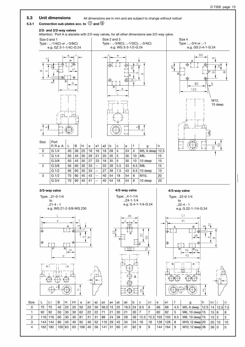
5.3 Unit dimensions5.3.1 Connection sub-plates acc. to ;; and ==
2/2- and 3/2-way valvesAttention: Port A is alsolete with 2/2-way valves, for all other dimensions see 3/2-way valve.
Size 0 and 1Type : ..-1/4(C) or ..-3/8(C)
e.g. GZ 3-1-1/4C-G 24
Size 2 and 3Type : ..-3/8(C); ..-1/2(C); ..-3/4(C)
e.g. WG 3-3-1/2-G 24
Size 4Type : ..-3/4 or ..-1
e.g. GS 2-4-1-G 24
All dimensions are in mm and are subject to change without notice!
Size L L1 B H H1 a a1 a2 a3 a4 a5 a6 b c c1 e e1 f g h
0 75 75 40 25 25 50 20 30 56.5 15 25 18.5 24 8.5 9 66 66 4.5 M5, 6 deep 12.5
1 92 92 50 30 30 62 22 22 71 21 30 21 30 7 7 82 82 5 M6, 10 deep 15
2 116 116 60 30 30 81 31 31 88 24 38 28 39 12.5 12.5 103 103 6.5 M8, 10 deep 15
3 144 144 80 40 40 92 46 52 110 29 43 34 54 18 18 128 128 8 M10, 12 deep 20
4 162 182 100 63 63 106 40 56 141 31 60 41 82 9 9 144 164 9 M12, 12 deep 38
h1 i i1
14 12.5 7.5
15 8 8
15 3 3
20 10 10
38 0 0
Type: ..21-0-1/4to
..21-4 - 1e.g. WG 21-2-3/8-WG 230
Type: ..22-0-1/4to
..22-4 - 1e.g. G 22-1-1/4-G 24
Type: ..4-1-1/4..Z4-1-1/4e.g. G 4-1-1/4-G 24
Size PortP, R a. A L B H a a1 a2 b c e f g h
0 G 1/4 40 36 25 16 16 18 28 4 24 4 M5, 6 deep 12.5
1 G 1/4 50 45 30 29 21 20 35 5 30 10 M6, 15
G 3/8 50 45 30 27 23 18 35 5 30 10 10 deep 15
2 G 3/8 56 60 30 33 -- 33 39 5.5 43 6.5 M8, 15
G 1/2 56 60 30 33 -- 27 39 7.5 43 6.5 10 deep 15
3 G 1/2 70 80 40 43 -- 40 54 18 54 8 M10, 20
G 3/4 70 80 40 41 -- 40 54 18 54 8 10 deep 20
M12,15 deep
3/3-way valve 4/2-way valve 4/3-way valve
D 7300 page 14
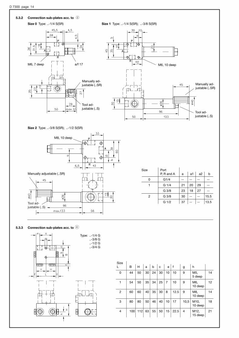
5.3.2 Connection sub-plates acc. to <Size 0 Type: ..-1/4 S(SR) Size 1 Type: ..-1/4 S(SR); ..-3/8 S(SR)
Size 2 Type: ..-3/8 S(SR); ..-1/2 S(SR)
5.3.3 Connection sub-plates acc. to >
Type: ..-1/4 G..-3/8 G..-1/2 G..-3/4 G
Size Port P, R and A a a1 a2 b
0 G1/4 -- -- -- --
1 G 1/4 21 20 29 --
G 3/8 23 18 27 --
2 G 3/8 30 -- -- 15.5
G 1/2 37 -- -- 13.5
SizeL B H a b c e f g h
0 44 50 30 24 30 10 10 9 M5, 145 deep
1 54 50 35 34 25 7 10 9 M6, 1210 deep
2 60 60 40 35 30 8 12.5 9 M8, 1410 deep
3 80 80 50 46 40 10 17 10,5 M10, 1810 deep
4 100 112 63 55 50 15 22.5 4 M12, 2115 deep
M6, 7 deep M6, 10 deep
M8, 10 deep
a/f 17
Manually ad-justable (..SR) Manually ad-
justable (..SR)
Manually adjustable (..SR)
Tool ad-justable (..S)
Tool ad-justable (..S)
Tool ad-justable (..S)

D 7300 page 15
6. Appendix6.1 Protection of directional seated valves against coarse contamination
Directional seated valves are rather unsensitive to ultra fine contamination always evident in hydraulicfluids. Nevertheless directional seated valves are fitted with screen filter elements with 0.25 mm meshwidth to prevent sudden disturbance caused by coarse contaminations that may occasionally becarried along in the oil (such as torn off particles of tubing, packing, scale swarf,) and which other-wise might get trapped at the valve seat gap.The sub-plates for individual valves (sect. 5) are fitted with fine screen filter discs HFC 1/4F 1 or HFC3/8 (acc. to D 7235) as standard at A and B with size 0, additionally in P with size 1. Valves size 2, 3and 4 with port size G 3/8, G 1/2 and G 3/4 may be retrofitted-. These screen filters are not availablefor G 1.These screen filter elements must not be understood as a replacement for usual hydraulic filters. Inpractice, however, they provide sufficient protection against malfunctions in small hydraulic systems.If such malfunctions should occur, the filter elements should be checked first.For the sake of simplicity, these filter elements are not explicitly shown in the diagrams.
Symbols
Individual valves acc. to section 3: Connection sub-plates acc. to section 5:
6.2 Versions for special fluids
' HFA (water / glycol solution, conforming VDMA 24317)The functionally essential parts are of stainless steel or tuffrided to prevent corrosion (valve balls, valve seat, actuation pin etc.).The valve body (size 3), external parts e.g. tapped plugs etc. are zinc galvanized.There are only 2/2-, 3/2- and 4/2-way directional seated valves available with flow pattern R2, S2, 3, a. Z3, 4, Z4 (see table 1 insect. 3.1)
Type coding: G 3-1-G 24 HFA
Flow Qperm. (l/min) approx. with reflowback pressure
1 bar 2 bar
3 4
5 6
14 18
36 45
Pres-surepmax
(bar)
400
Size
0
1
2
3
Throttles (cascade type or a coiled, small diameter pipe) should be installed at the pressure inlet to limit the flow down to permissible values for the applied pressure. This is to prevent cavitation and applies to all valves with return connection (3/2- und 4/2-way valves and 2/2-way valve as by-pass to the tank) or valves in circuits connected to an accumulator.
' Brake fluid based on glycolVersions equipped with EPDM (Ethylenpropylendien-rubber) seals suited for glycol based brake fluid or other special fluids.
Type coding: GR 2-2-G 24 AT
' Versions equipped with FKM (flour rubber, Viton) seals suited for some HFD type fluids (fire inhibiting, conforming VDMA 24317)
Type coding: WGS 2-0-WG 230 PYD
Screen filter elementstype HFC acc. to D 7235
Note:
A slight compensating force in the return pipe may be cre-ated by installing the tank at the highest possible location within the system.
2/2-wayvalve
3/2-wayvalve
2/2-wayvalve
3/2-wayvalve
3/3-wayvalve
4/2- and 4/3-wayvalve

D 7300 page 16
7. Mass (weight) approx. in kgBasic valve complete with actuation acc. to section 3 and 4
3/3-way valvesize
4/3-way valvesize
4/2-way valvesize
2/2- and 3/2-way valvesize
Actuationmode
0 1 2 3 4 0 1 2 3 4 0 1 2 3 1
Electrical G.. 0.4 0.65 1.2 3.1 7.2 0.8 1.4 2.9 5.9 16.3 0.9 1.6 3.0 6.0 1.9
WG.. 0.4 0.7 1.2 3.1 7.2 0.8 1.5 2.9 5.9 16.3 0.9 1.7 3.1 6.0 2.0
Hydraulic H.. 0.4 0.5 1.1 2.8 -- 0.8 1.1 2.7 5.2 -- 0.8 1.3 2.8 5.3 1,8
Pneumatic P.. 0.4 0.4 0.9 2.2 -- -- 0.9 2.3 4.1 -- -- 1.1 5.4 4.2 1.7
Act. roll K.. -- 0.4 0.8 2.0 -- -- 0.9 2.1 3.7 -- -- 1.1 5.2 3.8 1.7
Act. pin T.. -- 0.4 0.8 -- -- -- 0.8 2.1 -- -- -- 1.0 5.2 -- 1.6
Lever F.. -- 0.4 0.8 2.0 -- -- 0.9 2.1 3.7 -- -- 1.1 5.2 3.8 1.7
Turn knob D.. 0.4 0.4 0.9 -- -- 0.8 0.9 2.2 -- -- 0.8 1.1 5.3 -- 1.7
Connection sub-plates acc. to section 5Connection block only, for weight of the directional seated valves see above!
Size
0 1 2 3 4
Simple connection block ; 0.2 0.5 1.0 1.2 3.8
Connection block < with pressure limiting valve 0.4 1.2 1.6 -- --
Connection block = with by-pass check valve 0.2 0.5 1.0 -- --
Connection block > with rectifying circuit by means of check valves 0.5 0.7 1.0 2.4 4.7
Flow patternR2, S2 2/2-way valves3, Z3 3/2-way valves21 3/3-way valves22 4/3-way valves (not for size 4)4, Z4 4/2-way valves (size 1 only )
ActuationG Solenoid, DC versionWG Solenoid, AC version (50/60 Hz)H Hydraulic (not avail. size 4)P Pneumatic (not avail. for size 0 and 4)K Roll (not avail. for size 0 and 4)T Pin (not avail. for size 0, 3 and 4)F Key levers (not avail. for size 0 and 4)D Turn knob (not avail. for size 3 and 4)
Size0, 1, 2, 3, 4
Additional elements (option), see sect. 3.1R Check valve in port PB Orifice in port P S Return pressure stop in port R (size 0 and 1 only)RS, BS Combination of check valve or orifice with return pressure stop (size 0 and 1 only)
Connection sub-plates (option), see sect. 5-1/4, -3/8, -1/2, -3/4, -1 Simple connection block-1/4S, -3/8S, -1/2S Connection block with pressure limiting valve-1/4SR, -3/8SR, -1/2SR Connection block manually adjustable pressure
limiting valve-1/4C, -3/8C, -1/2C, -3/4C Connection block with by-pass check valve
(2/2-directional valves only)-1/4G, -3/8G, -1/2G, -3/4G Connection block with rectifying circuit by means of check
valves (2/2-directional valves only)
Additional information (option)e.g. special voltage, special fluids, pressure setting (sect. 4.1; 5.1; 6.2)
G R 2 - 2 R - G 24
WG 3 - 1 -1/2S - WG 110 - 230H 22 - 3
Mec
ha-
nica
lM
an-
ual
8. Type overview
Type
Solenoid voltage (standard)