directly operated solenoid valves series a solenoid valves … · 2014-11-27 · construction...
TRANSCRIPT
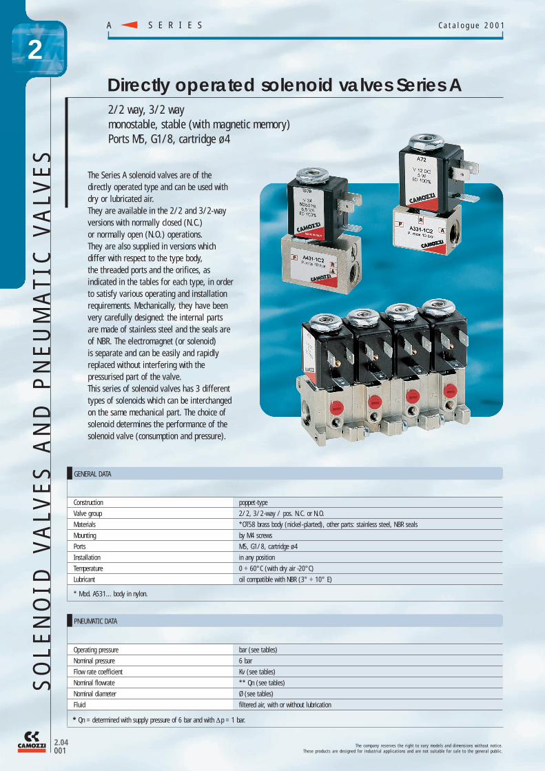
2/2 way, 3/2 waymonostable, stable (with magnetic memory)Ports M5, G1/8, cartridge ø 4
Directly operated solenoid valves Series A
Construction poppet - type
Valve group 2/2, 3/2-way / pos. N.C. or N.O.
Materials *OT58 brass body (nickel - plarted), other parts: stainless steel, NBR seals
Mounting by M4 screws
Ports M5, G1/8, cartridge ø 4
Installation in any position
Temperature 0 ÷ 60°C (with dry air -20°C)
Lubricant oil compatible with NBR (3° ÷ 10° E)
* Mod. A531... body in nylon.
Operating pressure bar (see tables)
Nominal pressure 6 bar
Flow rate coefficient Kv (see tables)
Nominal flowrate ** Qn (see tables)
Nominal diameter Ø (see tables)
Fluid filtered air, with or without lubrication
PNEUMATIC DATA
T h e c o m p a n y r e s e r v e s t h e r i g h t t o v a r y m o d e l s a n d d i m e n s i o n s w i t h o u t n o t i c e .T h e s e p r o d u c t s a r e d e s i g n e d f o r i n d u s t r i a l a p p l i c a t i o n s a n d a r e n o t s u i t a b l e f o r s a l e t o t h e g e n e r a l p u b l i c .
GENERAL DATA
S E R I E SA C a t a l o g u e 2 0 0 1
2.04001
The Series A solenoid valves are of thedirectly operated type and can be used withdry or lubricated air.They are available in the 2/2 and 3/2-wayversions with normally closed (N.C.)or normally open (N.O.) operations.They are also supplied in versions whichdiffer with respect to the type body,the threaded ports and the orifices, asindicated in the tables for each type, in orderto satisfy various operating and installationrequirements. Mechanically, they have beenvery carefully designed: the internal partsare made of stainless steel and the seals areof NBR. The electromagnet (or solenoid)is separate and can be easily and rapidlyreplaced without interfering with the pressurised part of the valve.This series of solenoid valves has 3 differenttypes of solenoids which can be interchangedon the same mechanical part. The choice ofsolenoid determines the performance of thesolenoid valve (consumption and pressure).
2
* Qn = determined with supply pressure of 6 bar and with ∆p = 1 bar.
SO
LE
NO
ID V
ALV
ES
AN
D P
NE
UM
ATI
C V
ALV
ES

Fig. 1
A331-0C2-A77
PORTSP A R
0 M5 M5 M51 G1/8 G1/8 M53 M5 G1/8 male M5
4 M5 G1/8 male M5(with manual override)
ORA rotatable
O-ringinterface
fixedB O-ring
interfaceC cartridge ø 4 (manifold only)
T h e c o m p a n y r e s e r v e s t h e r i g h t t o v a r y m o d e l s a n d d i m e n s i o n s w i t h o u t n o t i c e .T h e s e p r o d u c t s a r e d e s i g n e d f o r i n d u s t r i a l a p p l i c a t i o n s a n d a r e n o t s u i t a b l e f o r s a l e t o t h e g e n e r a l p u b l i c .
2.04002
S E R I E S AC a t a l o g u e 2 0 0 1
2
Mod. A80 Mod. A70 Mod. G90
Solenoids for Series "A" solenoid valves
The solenoids for Series A solenoid valves, models A70and A80, are of the monostable type (see connection diagram in Fig. 1). The dimensions as well as the powerconsumption of these solenoids differ so that the best possible choice can be made depending on the type ofelectronic or electromechanical operating system used.The model G90 is a special type of solenoid for pulsedoperation. A short pulse, with a maximum duration of 20ms, causes the poppet to be engaged; another short pulseon the secondary circuit causes it to be released.Repeated pulses on the same circuit do not change theposition of the poppet. This feature allows a Series "A"solenoid valve to be converted from an monostable typeto a stable type, without modifying any mechanical parts.
CODING OF SERIES A SOLENOID VALVES
SERIES A
BODY DESIGN1 = base (24 x 24 mm)
interface rotatable through 360°
2 = base (24 x 24 mm)fixed interface
3 = threaded body4 = rapid exhaust body5 = base with ISO standard
interface, fixed6 = base (16 x 16 mm)
interface rotatable through 360°
7 = base with side interface,rotatable through 360°
A = single manifold B = 2 - part manifold C = 3 - part manifoldD = 4 - part manifoldE = 5 - part manifoldiF = 6 - part manifoldG = 7 - part manifoldH = 8 - part manifoldK = 9 - part manifoldL = 10 - part manifoldM = 11 - part manifoldN = 12 - part manifoldP = 13 - part manifoldR = 14 - part manifoldS = 15 - part manifold
N° OF PORTS2 = 2 way3 = 3 way
ENCAPSULATING MATERIALA = PPS G = nylon (glass reinforced)
BODY MATERIAL1 = Aluminium2 = OT58 brass
SOLENOID DIMENSIONS7 = 22 x 228 = 30 x 309 = 22 x 58
SOLENOID VOLTAGE ■A70 G70 A80 G90
B = 24V 50/60 Hz ■ - ■ ■
C = 48V 50/60 Hz ■ - - ■
D = 110V 50/60 Hz ■ - ■ -E = 220V 50/60 Hz ■ - ■ -
* H=24V 50/60Hz ■ - - -* K=110V 50/60Hz ■ - - -* J=220V 50/60Hz ■ - - -
2 = 12V DC ■ - - ■3 = 24V DC ■ ■ ■ ■
4 = 48V DC ■ - ■ ■
6 = 110V DC ■ - ■ -* 7 = 24V RC ■ - - -
Note: The voltages indicated are standard voltages, for spacial voltages contact our technical department.*for 2/2 N.C. solenoid valves contact our engineers.
NOMINAL DIAMETERC = 1,5D = 2E = 2,5
FUNCTION1 = NC (normally closed)2 = NO (normally open)
LINE
A70
A80
SO
LE
NO
ID V
ALV
ES
AN
D P
NE
UM
ATIC
VA
LVE
S

Mod. Voltage Minimum pulse ConsumptionV ms (20°C) mA
latch released latch released
G92 12 DC 18 10 325 160G93 24 DC 18 10 168 80G94 42 DC 18 10 68 35
48 DC 18 10 80 40G9B 24 50/60 20 15 185 10G9C 48 50/60 20 15 92 54
SOLENOID VOLTAGESI A70 SOLENOID VOLTAGES G70
Mod.A7B 24V 50/60 Hz 6,2VAA7C 48V 50/60 Hz 7,2VAA7D 110V 50/60 Hz 6,6VAA7E 220V 50/60 Hz 7,2VA
Mod.A7H 24V 50/60 Hz 3,7VAA7K 110V 50/60 Hz 4VAA7J 220V 50/60 Hz 4VAA72 12V DC 5W
Mod.A73 24V DC 5WA74 48V DC 5WA76 110V DC 4,2WA77 24V DC 3W
ModG73 24V DC 5W
SOLENOID VOLTAGES A80
Mod.A8B 24V 50/60 Hz 5VAA8D 110V 50/60 Hz 5VAA8E 220V 50/60 Hz 5VA
Mod.A83 24V DC 4WA84 48V DC 4WA86 110V DC 4W
T h e c o m p a n y r e s e r v e s t h e r i g h t t o v a r y m o d e l s a n d d i m e n s i o n s w i t h o u t n o t i c e .T h e s e p r o d u c t s a r e d e s i g n e d f o r i n d u s t r i a l a p p l i c a t i o n s a n d a r e n o t s u i t a b l e f o r s a l e t o t h e g e n e r a l p u b l i c .
S E R I E SA C a t a l o g u e 2 0 0 1
2.04003
2
Nominal dimensions: 22 x22Protection class: IP54 - DIN 40050 (PPS)
IP65 (with connector Mod. 122-800)Insulation: Class H (180°C), test at 3000 V for 1 minConnections: Bipolar plus earth DIN 43650 (version B)Voltage tolerance: AC +10% - 15%
DC ±10%100%, continuous operation.
Solenoid for Series "A" solenoid valve Mod. A70
Nominal dimensions: 30 x 30Protection class: IP54, DIN 40050
IP65 (with connector Mod. 124-800)Insulation: Class H (180°C), test at 3000 V for 1 minConnections: Bipolar plus earth DIN 43650 (version A)Voltage tolerance: AC +10% - 15%
DC ±10%100%, continuous operation.
Solenoid for Series "A" solenoid valve Mod. A80
Nominal dimensions: 22 x 58Protection class: IP54, DIN 40050 (glass-reinforced nylon), IP65 (with connector Mod. 128-800)Insulation: class F (155°C), test at 1500 V for 1'Connections: tripolar (see diagrams) DIN 43650 (version B)Voltage tolerance: DC and AC ±10%Operation: pulsed (see explanation), 100%, continuous operation.
Solenoid for Series "A" solenoid valve Mod. G90 (with memory)
SO
LE
NO
ID V
ALV
ES
AN
D P
NE
UM
ATI
C V
ALV
ES

Latch
min. 20m/sec
ON
ON
OFF
OFF
min. 10m/sec
Latch
Fig. 2 - SUPPLY C.A.
Fig. 1
Fig. 3 - SUPPLY C.C.
Fig. 4 - PLC OPERATING
Release
Release
Latch
Release
Outlets PLC
Latch
Release
ComuneConnector
T h e c o m p a n y r e s e r v e s t h e r i g h t t o v a r y m o d e l s a n d d i m e n s i o n s w i t h o u t n o t i c e .T h e s e p r o d u c t s a r e d e s i g n e d f o r i n d u s t r i a l a p p l i c a t i o n s a n d a r e n o t s u i t a b l e f o r s a l e t o t h e g e n e r a l p u b l i c .
2.04004
S E R I E S AC a t a l o g u e 2 0 0 1
2
Mod. G90 solenoid valves (coils) can be replaced on all other Series A solenoid valves or pilots(22 x 22) allowing to change the valve functioning from:- monostable functioning system (spring return)
closed circuit = attracted magnetic = opened poppet if NC, closed if NO.opened circuit = released magnetic = closed poppet if NC, opened if NO.
- to stable functioning system (memory)impulse on A circuit = attracted magnetic (latched)impulse on B circuit = released magnetic (unlatched)
the stable functioning has the following advantages:- the solenoid valve consumption is practically none as the open and close control occurs thanks
to an impulse of about 20 m/s after which the valve always remains in the controlled position,without any feeding until the inverse impulse which changes the position is sent.
- the valve remains in the controlled position (opened or closed) even when the electricalfeeding of the installation where the valve is inserted is missing, allowing the valve to be used as a position memory.
- when normally opened valves should be used, it is not necessary to use valves with special (reverse) mechanical parts as a NC valve becomes a NO valve just by changing the control impulse sequence.
- The impulse control system facilitates the utilization with electronic circuits. The minimum required impulse for the function is 20 ms; if, for circuit reasons, the impulse last for a longerperiod, there is no danger of heating as the solenoid has been designed to work also with 100% ED.
General operating data.The control of G90 solenoid valves is effected by impulses:- magnetic attraction control = latched (A)- magnetic release control = unlatched (B)Assuming a normally closed valve, the situation is:- Unlatched = open valve- Latched = closed valve
During the control sequence, one has to wait for at least 10 ms between a latch control and aunlatch control on the same valve (see Fig. 1). When the G90 solenoid valves are assembledon a manifold between each others, or with normal type valves, a G90/L magnetic shield hasto be used in order to avoid magnetic interferences. The solenoid valve has three terminalsnumbered 1, 2, 3 and the electrical connections for the exchange are indicated in the following.Control circuits:- For alternating current (fig. 2) tables. The control is effected through closing contacts
on terminals 1 and 2, whereas terminal 3 is steadily connected to a phase.Caution: do not invert terminal 3 with terminals 1 and 2 as this could cause a short circuit. When controls with PLC are used, keep in mind that the coil is bi-functional, terminal 3 should be connected to the neutral wire whereas terminal 1 should be connected at the end of the unlatch control, and terminal 2 at the end of the latch control.
- For direct current (fig. 3). The control is effected through two switching contacts which reverse the sense of the current to the coil through terminals 1 and 2 (terminal 3 is not used).In order to simplify the control system, an electronic interface can be used. This electronic interface is made up of a normal connector with a circuit which effected the current inversion to the spool thanks to a single control and two contacts, as for alternate current type.The interface is necessary for the PLC control in direct current. Fig. 4 indicates the valveconnection to the PLC in direct current. With special electronic connector of 122-892P type with positive wire and 122-893N with negative wire.
Note: Please ask for special instructions. The terminal sizes are shown on page 2.31.003.
Solenoid Mod. G90
SO
LE
NO
ID V
ALV
ES
AN
D P
NE
UM
ATIC
VA
LVE
S
Mod. N° terminal Function Terminal polarity2 latched negative
122-892 1 unlatched negative3 basic (neutral wire) positive1 latched positive
122-893 2 unlatched positive3 basic (neutral wire) negative

Thread. Function Orifice Kv L/min (H20) Qn Nl/min Press. min-maxMod. port. barAA31-0C2-000* M5 N.C. 1.5 0.8 62 0 ÷ 10AA31-CC2-000* ø 4 N.C. 1.5 0.6 55 0 ÷ 10
Thread. Function Orifice Kv L/min (H20) Qn Nl/min Press. min-maxMod. port. barA321-0C2-000* M5 N.C. 1.5 0.9 63 0 ÷15A321-1C2-000* G1/8 N.C. 1.5 1.1 68 0 ÷15A321-1D2-000* G1/8 N.C. 2 1.8 111 0 ÷ 9A321-1E2-000* G1/8 N.C. 2.5 2.2 160 0 ÷ 6A322-0C2-000* M5 N.O. 1.8 1 91 0 ÷ 10A322-1C2-000* G1/8 N.O. 1.8 1.1 96 0 ÷ 10A331-0C2-000* M5 N.C. 1.5 0.8 60 0 ÷ 10A331-1C2-000* G1/8 N.C. 1.5 1 66 0 ÷ 10A332-0C2-000* M5 N.O. 1.5 0.7 53 0 ÷ 6A332-1C2-000* G1/8 N.O. 1.5 0.8 60 0 ÷ 6
T h e c o m p a n y r e s e r v e s t h e r i g h t t o v a r y m o d e l s a n d d i m e n s i o n s w i t h o u t n o t i c e .T h e s e p r o d u c t s a r e d e s i g n e d f o r i n d u s t r i a l a p p l i c a t i o n s a n d a r e n o t s u i t a b l e f o r s a l e t o t h e g e n e r a l p u b l i c .
S E R I E SA C a t a l o g u e 2 0 0 1
2.04005
2
2/2 and 3/2-way solenoid valves Mod. A32... and Mod. A33...
The 3/2 - way solenoid valves for manifold assembly are available in the N.C.(normally closed) version, with 1/8" ports at the manifold inlet,and may be used with M5 threading or with a dia. 4 cartridge.These solenoid valve are provided with a manual over ride protectedagainst accidental operation and may be stable or monostable.The body is supplied complete with O-ring and screws.
3/2-way solenoid valve 3/2 Mod. AA31...
The 2/2 and 3/2 - way solenoid valves, for individual assembly,are available for normally closed or normally open operation.The ports on the body may be G1/8 or M5, while the outlet which is provided is always M5.
*Choose solenoid required.
*choose solenoid required.
SO
LE
NO
ID V
ALV
ES
AN
D P
NE
UM
ATI
C V
ALV
ES

Thread. Function Orifice Kv L/min (H20) Qn Nl/min Press. min-maxMod. port. barA331-3C2-000* - N.C. 1.5 1 70 0 ÷ 10A331-4C2-000* - N.C. 1.5 1 70 0 ÷ 10
SO
LE
NO
ID V
ALV
ES
AN
D P
NE
UM
ATIC
VA
LVE
S
T h e c o m p a n y r e s e r v e s t h e r i g h t t o v a r y m o d e l s a n d d i m e n s i o n s w i t h o u t n o t i c e .T h e s e p r o d u c t s a r e d e s i g n e d f o r i n d u s t r i a l a p p l i c a t i o n s a n d a r e n o t s u i t a b l e f o r s a l e t o t h e g e n e r a l p u b l i c .
2.04006
S E R I E S AC a t a l o g u e 2 0 0 1
2
Thread. Function Orifice Kv L/min (H20) Qn Nl/min Press. min-maxMod. port. barA431-1C2-000* - N.C. 1.5 1 70 0 ÷ 10
The 3/2 - way NC solenoid valve, with G1/8 ports, incorporates a rapid exhaust valve.This feature allows not only the dimensions to be reduced, but also the exhaust time to be reduced.It is particularly suitable for operating small single-acting cylinders and pressurising small compressed air containers.
3/2-way solenoid valve Mod. A43...
*choose solenoid required.
The 3/2-way NC solenoid valve has been designed principallyfor two very important applications: the actuation of small single-acting cylinders and the operation of pneumatic valveswith very low operating pressures.The body has an outlet with a G1/8 male thread which can be screwed directly onto the component to be operated. The inlet port is MS threaded.
3/2-way solenoid valve Mod. A33...
*choose solenoid required.
Thread. Function Orifice Kv L/min (H20) Qn Nl/min Press. min-maxMod. port. barA631-AC2-000* OR N.C. 1.5 1 70 0 ÷ 10
The 3/2 - way NC solenoid valve, which has a rotating interface, is designed to be mounted directly onto machine parts by two screws.A sealing action is ensured by two concentric O-rings which allow the body to be adjusted through 360°.These solenoid valves are provided with a manual over ride for stable or monostable operation.
3/2-way solenoid valve Mod. A63...
*choose solenoid required.

Thread Function Orifice Kv L/min (H20) Qn Nl/min Press. min-maxMod. port barA231-BC2-000* OR N.C. 1.5 1 70 0 ÷ 10
T h e c o m p a n y r e s e r v e s t h e r i g h t t o v a r y m o d e l s a n d d i m e n s i o n s w i t h o u t n o t i c e .T h e s e p r o d u c t s a r e d e s i g n e d f o r i n d u s t r i a l a p p l i c a t i o n s a n d a r e n o t s u i t a b l e f o r s a l e t o t h e g e n e r a l p u b l i c .
S E R I E SA C a t a l o g u e 2 0 0 1
2.04007
2
Thread Function Orifice Kv L/min (H20) Qn Nl/min Press. min-maxMod. port barA531-BC2-000* OR N.C. 1.5 1 70 0 ÷ 10
The 3/2 - way N.C. solenoid valve, which has an interface fixed at 90°C relative to the axis, has been designed so as to be mounted on valves with an ISO interface.The interface is interchangeable with all ISO version.These solenoid valves are equipped with a manual over ride for stable and monostable operation.
3/2 - way solenoid valve Mod. A53...
*choose solenoid required.
The 3/2 way N.C. solenoid valve, which has a fixed interface,is designed so as to be mounted directly onto machine partsby two screws. The sealing is ensured by two O-rings whichensure a particularly effective joint.These solenoid valves are equipped with a manual over ridefor stable and monostable operation.
3/2-way solenoid valve Mod. A23...
*choose solenoid required.
SO
LE
NO
ID V
ALV
ES
AN
D P
NE
UM
ATI
C V
ALV
ES

FOR SERIES 6 AND SERIES A80 COILS
Mod.124-800 DIN 43650 (PG9)
FOR SERIES G90
Mod.122-892C P122-893C N
FOR SERIES A70
Mod.122-800 DIN 43650 (PG9)
T h e c o m p a n y r e s e r v e s t h e r i g h t t o v a r y m o d e l s a n d d i m e n s i o n s w i t h o u t n o t i c e .T h e s e p r o d u c t s a r e d e s i g n e d f o r i n d u s t r i a l a p p l i c a t i o n s a n d a r e n o t s u i t a b l e f o r s a l e t o t h e g e n e r a l p u b l i c .
2.04008
S E R I E S AC a t a l o g u e 2 0 0 1
2
Adapted for G90 solenoids (with memory)in 12 V.D.C. - 24 V.D.C.
Special connectors with integrated electronic circuit and pre-wired moulded cable (L = 2 m)
Thread Function Orifice Kv L/min (H20) Qn Nl/min Press. min-maxMod. port barA131-AC2-000* OR N.C. 1.5 1 70 0 ÷ 10
The 3/2 - way N.C. solenoid valve, which has a rotating interface, is designed so as to be mounted directlyonto machine parts two screws.The sealing is ensured by two concentric O - rings which allow the body to be adjusted through 360°.These solenoid valves are equipped with a manual over ride for monostable and stable operation.
3/2-way solenoid valve Mod. A13...
*choose solenoid required.
SO
LE
NO
ID V
ALV
ES
AN
D P
NE
UM
ATIC
VA
LVE
S