direcway prodelin 1.8meter assembly instructions
TRANSCRIPT
4096-394
January 14, 2002
REVISION GASSEMBLY MANUAL
1.8 METERSERIES 1194 ANTENNA SYSTEM
PRODELIN CORPORATION1500 Prodelin Drive
Newton NC 28658
4096-394PRODELIN CORPORATION 1.8M SERIES 1194
2
1.8 METER SERIES 1194ANTENNA SYSTEM
G Revise Address 1/14/02
F Revise Flat washers to 8 5/15/01 RAH
E Revised part list on page 8 1/22/99 RAH
D Revise Step 9 Pg. 12. ¾” was ½” nut. 03/26/98 PGW
C Revised It. 5 – pg. 8 , was 8033-012 11/05/97 PGWB Updated 04/21/97 PGWA Revised Page #19 10/03/95 R. Frye- ORIGINAL RELEASE 02/02/95 R. Frye
REV. DESCRIPTION DATE APPROVED
4096-394PRODELIN CORPORATION 1.8M SERIES 1194
3
1.8M SERIES 1194 ANTENNA SYSTEM
TABLE OF CONTENTS
SECTION I GENERAL INFORMATION ....................................................................... 51.0 INTRODUCTION ....................................................................................... 51.1 UNPACKING AND INSPECTION.............................................................. 51.2 FREIGHT DAMAGE .................................................................................. 51.3 MATERIAL - MISSING OR DAMAGED .................................................... 51.4 MECHANICAL INSTALLATION TOOLS .................................................. 61.5 FOUNDATION INTERFACE ..................................................................... 61.6 SUGGESTED MAST & FOUNDATION..................................................... 7
SECTION II ANTENNA SYSTEM ASSEMBLY............................................................. 92.0 ANTENNA ASSEMBLY ............................................................................ 92.1 FEED SUPPORT ASSEMBLY ................................................................ 14
SECTION III ANTENNA POINTING............................................................................. 183.0 ANTENNA POINTING............................................................................. 18
SECTION IV MAINTENANCE ...................................................................................... 204.0 MAINTENANCE OVERVIEW .................................................................. 204.1 PERIODIC INSPECTION......................................................................... 204.2 REFLECTOR........................................................................................... 204.3 MOUNT AND REFLECTOR SUPPORT STRUCTURE........................... 214.4 FEED AND FEED SUPPORT.................................................................. 21
4096-394PRODELIN CORPORATION 1.8M SERIES 1194
4
4096-394PRODELIN CORPORATION 1.8M SERIES 1194
5
SECTION I GENERAL INFORMATION
1.0 INTRODUCTION
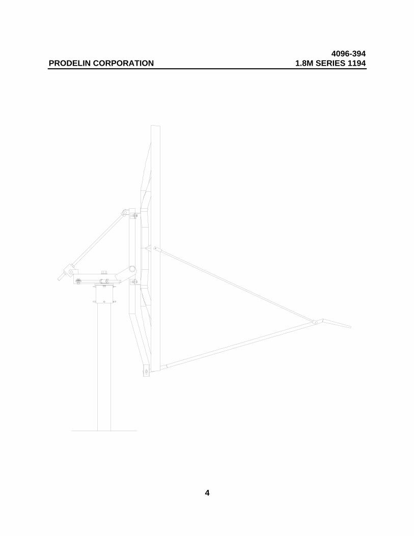
This manual describes the assembly and installation of Prodelin's 1.8M Rx/Txoffset antenna system with an Az/El mount (series number 1194). The Prodelin1.8M is a rugged, reliable antenna system, which will operate in the 10.95 to12.75 and 14.0 to 14.5 GHz frequency bands for Ku-Band systems with highefficiency and at the same time successfully withstand the effects of theenvironment.
These instructions are listed by sections that cover all areas of assembly andinstallation. Additional sections are included in the manual to provide informationon antenna alignment to the satellite and maintenance.
1.1 UNPACKING AND INSPECTION
The antenna containers should be unpacked and inspected at the earliest date toensure that all material has been received and is in good condition. A completepacking list for each major component is supplied.
1.2 FREIGHT DAMAGE
Any damage to materials while in transit should be immediately directed to thefreight carrier. He will instruct you on matters regarding any freight damageclaims.
1.3 MATERIAL - MISSING OR DAMAGED
Any questions regarding missing or damaged materials that is not due to thefreight carrier should be directed to Prodelin's Customer Service Department at:
PRODELIN CORPORATION1500 Prodelin DriveNewton NC 28658
USA(828) 464-4141
1.4 MECHANICAL INSTALLATION TOOLS
4096-394PRODELIN CORPORATION 1.8M SERIES 1194
6
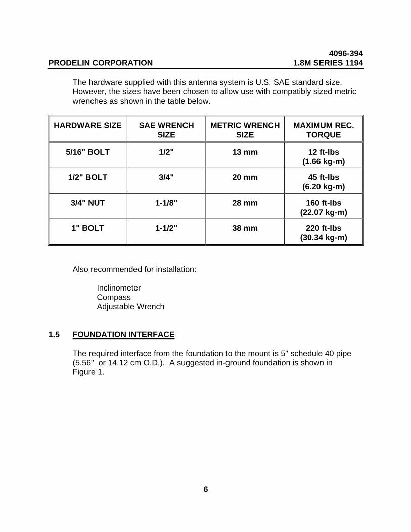
The hardware supplied with this antenna system is U.S. SAE standard size. However, the sizes have been chosen to allow use with compatibly sized metricwrenches as shown in the table below.
HARDWARE SIZE SAE WRENCHSIZE
METRIC WRENCHSIZE
MAXIMUM REC.TORQUE
5/16" BOLT 1/2" 13 mm 12 ft-lbs(1.66 kg-m)
1/2" BOLT 3/4" 20 mm 45 ft-lbs(6.20 kg-m)
3/4" NUT 1-1/8" 28 mm 160 ft-lbs(22.07 kg-m)
1" BOLT 1-1/2" 38 mm 220 ft-lbs(30.34 kg-m)
Also recommended for installation:
InclinometerCompassAdjustable Wrench
1.5 FOUNDATION INTERFACE
The required interface from the foundation to the mount is 5" schedule 40 pipe(5.56" or 14.12 cm O.D.). A suggested in-ground foundation is shown inFigure 1.
4096-394PRODELIN CORPORATION 1.8M SERIES 1194
7
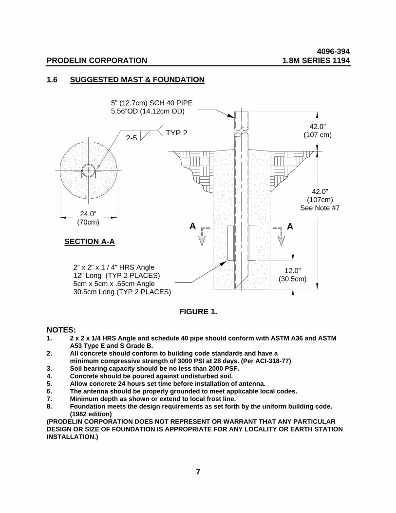
1.6 SUGGESTED MAST & FOUNDATION
FIGURE 1.
NOTES:1. 2 x 2 x 1/4 HRS Angle and schedule 40 pipe should conform with ASTM A36 and ASTM
A53 Type E and S Grade B.2. All concrete should conform to building code standards and have a
minimum compressive strength of 3000 PSI at 28 days. (Per ACI-318-77)3. Soil bearing capacity should be no less than 2000 PSF.4. Concrete should be poured against undisturbed soil.5. Allow concrete 24 hours set time before installation of antenna.6. The antenna should be properly grounded to meet applicable local codes.7. Minimum depth as shown or extend to local frost line.8. Foundation meets the design requirements as set forth by the uniform building code.
(1982 edition)(PRODELIN CORPORATION DOES NOT REPRESENT OR WARRANT THAT ANY PARTICULARDESIGN OR SIZE OF FOUNDATION IS APPROPRIATE FOR ANY LOCALITY OR EARTH STATIONINSTALLATION.)
2-5TYP 2
42.0”(107 cm)
42.0”(107cm)
See Note #7
AA
12.0”(30.5cm)
24.0”(70cm)
5” (12.7cm) SCH 40 PIPE5.56”OD (14.12cm OD)
2” x 2” x 1 / 4” HRS Angle 12” Long (TYP 2 PLACES)5cm x 5cm x .65cm Angle30.5cm Long (TYP 2 PLACES)
SECTION A-A
2-5 TYP 2
4096-394PRODELIN CORPORATION 1.8M SERIES 1194
8
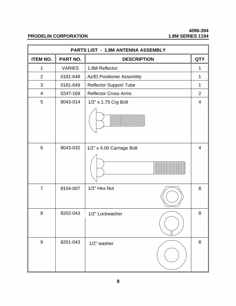
PARTS LIST - 1.8M ANTENNA ASSEMBLY
ITEM NO. PART NO. DESCRIPTION QTY
1 VARIES 1.8M Reflector 1
2 0181-648 Az/El Positioner Assembly 1
3 0181-649 Reflector Support Tube 1
4 0247-169 Reflector Cross Arms 2
5 8043-014 4
6 8043-032 4
7 8104-007 8
8 8202-043
8
9 8201-043
8
1/2” x 1.75 Crg Bolt
1/2” x 4.00 Carriage Bolt
1/2” Hex Nut
1/2” Lockwasher
1/2” washer
4096-394PRODELIN CORPORATION 1.8M SERIES 1194
9
SECTION II ANTENNA SYSTEM ASSEMBLY
CAUTION: During the assembly procedure, the sequence of instructions must befollowed. Do Not Tighten Any Hardware Until Instructed. Refer tothe antenna assembly parts list and the following steps.
2.0 ANTENNA ASSEMBLY
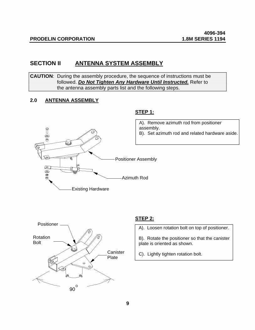
STEP 1:
STEP 2:
A). Remove azimuth rod from positionerassembly.B). Set azimuth rod and related hardware aside.
Existing Hardware
Azimuth Rod
Positioner Assembly
A). Loosen rotation bolt on top of positioner.
B). Rotate the positioner so that the canisterplate is oriented as shown.
C). Lightly tighten rotation bolt.
90
RotationBolt
CanisterPlate
Positioner
4096-394PRODELIN CORPORATION 1.8M SERIES 1194
10
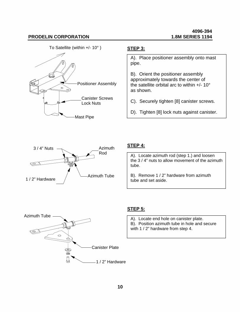
STEP 3:
STEP 4:
STEP 5:
A). Place positioner assembly onto mastpipe.
B). Orient the positioner assemblyapproximately towards the center ofthe satellite orbital arc to within +/- 10°as shown.
C). Securely tighten [8] canister screws.
D). Tighten [8] lock nuts against canister.Mast Pipe
To Satellite (within +/- 10° )
Positioner Assembly
Canister ScrewsLock Nuts
A). Locate azimuth rod (step 1.) and loosenthe 3 / 4” nuts to allow movement of the azimuthtube.
B). Remove 1 / 2” hardware from azimuthtube and set aside.1 / 2” Hardware
Azimuth Tube
3 / 4” Nuts AzimuthRod
A). Locate end hole on canister plate.B). Position azimuth tube in hole and securewith 1 / 2” hardware from step 4.
1 / 2” Hardware
Canister Plate
Azimuth Tube
4096-394PRODELIN CORPORATION 1.8M SERIES 1194
11
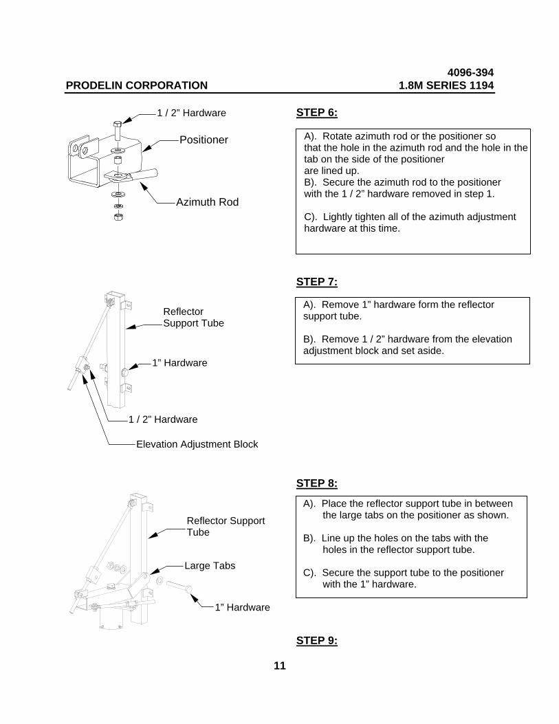
STEP 6:
STEP 7:
STEP 8:
STEP 9:
A). Rotate azimuth rod or the positioner sothat the hole in the azimuth rod and the hole in thetab on the side of the positionerare lined up.B). Secure the azimuth rod to the positionerwith the 1 / 2” hardware removed in step 1.
C). Lightly tighten all of the azimuth adjustmenthardware at this time.
1 / 2” Hardware
Positioner
Azimuth Rod
A). Remove 1” hardware form the reflectorsupport tube.
B). Remove 1 / 2” hardware from the elevationadjustment block and set aside.
1” Hardware
ReflectorSupport Tube
1 / 2” Hardware
Elevation Adjustment Block
A). Place the reflector support tube in between the large tabs on the positioner as shown.
B). Line up the holes on the tabs with the holes in the reflector support tube.
C). Secure the support tube to the positioner with the 1” hardware.
1” Hardware
Large Tabs
Reflector Support Tube
4096-394PRODELIN CORPORATION 1.8M SERIES 1194
12
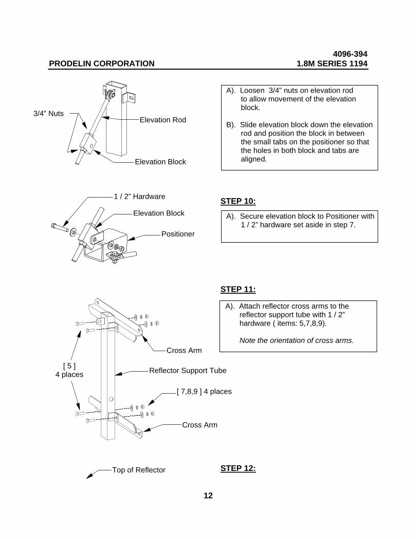
STEP 10:
STEP 11:
STEP 12:
A). Loosen 3/4” nuts on elevation rod to allow movement of the elevation block.
B). Slide elevation block down the elevation rod and position the block in between the small tabs on the positioner so that the holes in both block and tabs are aligned.
Elevation Rod
Top of Reflector
Elevation Block
3/4” Nuts
A). Secure elevation block to Positioner with 1 / 2” hardware set aside in step 7.
Elevation Block
1 / 2” Hardware
Positioner
A). Attach reflector cross arms to the reflector support tube with 1 / 2” hardware ( items: 5,7,8,9).
Note the orientation of cross arms. Cross Arm
[ 7,8,9 ] 4 places
Reflector Support Tube
Cross Arm
[ 5 ]4 places
4096-394PRODELIN CORPORATION 1.8M SERIES 1194
13
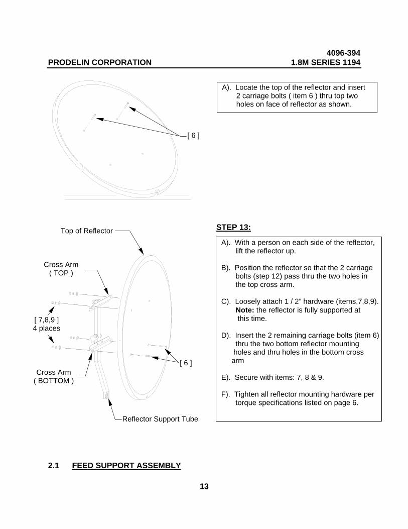
STEP 13:
2.1 FEED SUPPORT ASSEMBLY
A). Locate the top of the reflector and insert 2 carriage bolts ( item 6 ) thru top two holes on face of reflector as shown.
[ 6 ]
A). With a person on each side of the reflector, lift the reflector up.
B). Position the reflector so that the 2 carriage bolts (step 12) pass thru the two holes in the top cross arm.
C). Loosely attach 1 / 2” hardware (items,7,8,9). Note: the reflector is fully supported at this time.
D). Insert the 2 remaining carriage bolts (item 6) thru the two bottom reflector mounting holes and thru holes in the bottom cross arm
E). Secure with items: 7, 8 & 9.
F). Tighten all reflector mounting hardware per torque specifications listed on page 6.
Top of Reflector
Cross Arm( TOP )
Cross Arm( BOTTOM )
[ 7,8,9 ]4 places
[ 6 ]
Reflector Support Tube
4096-394PRODELIN CORPORATION 1.8M SERIES 1194
14
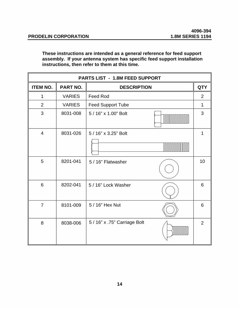
These instructions are intended as a general reference for feed supportassembly. If your antenna system has specific feed support installationinstructions, then refer to them at this time.
PARTS LIST - 1.8M FEED SUPPORT
ITEM NO. PART NO. DESCRIPTION QTY
1 VARIES Feed Rod 2
2 VARIES Feed Support Tube 1
3 8031-008 3
4 8031-026 1
5 8201-041 10
6 8202-041 6
7 8101-009 6
8 8038-006 2
5 / 16” x 1.00” Bolt
5 / 16” x 3.25” Bolt
5 / 16” Flatwasher
5 / 16” Lock Washer
5 / 16” Hex Nut
5 / 16” x .75” Carriage Bolt
4096-394PRODELIN CORPORATION 1.8M SERIES 1194
15
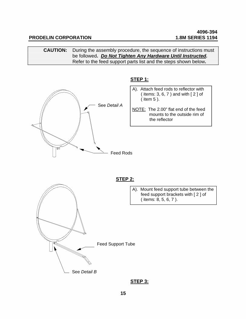
CAUTION: During the assembly procedure, the sequence of instructions mustbe followed. Do Not Tighten Any Hardware Until Instructed.Refer to the feed support parts list and the steps shown below.
STEP 1:
STEP 2:
STEP 3:
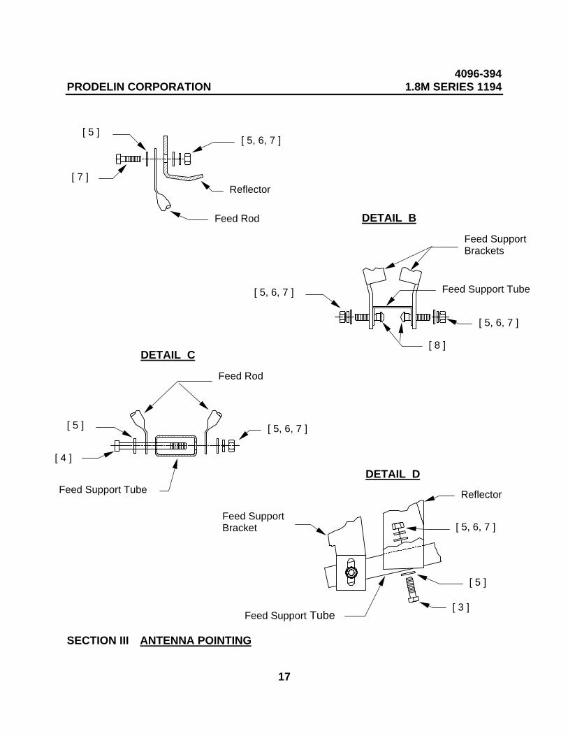
A). Attach feed rods to reflector with ( items: 3, 6, 7 ) and with [ 2 ] of ( item 5 ).
NOTE: The 2.00” flat end of the feed mounts to the outside rim of
the reflector
Feed Rods
See Detail A
A). Mount feed support tube between the feed support brackets with [ 2 ] of ( items: 8, 5, 6, 7 ).
Feed Support Tube
See Detail B
4096-394PRODELIN CORPORATION 1.8M SERIES 1194
16
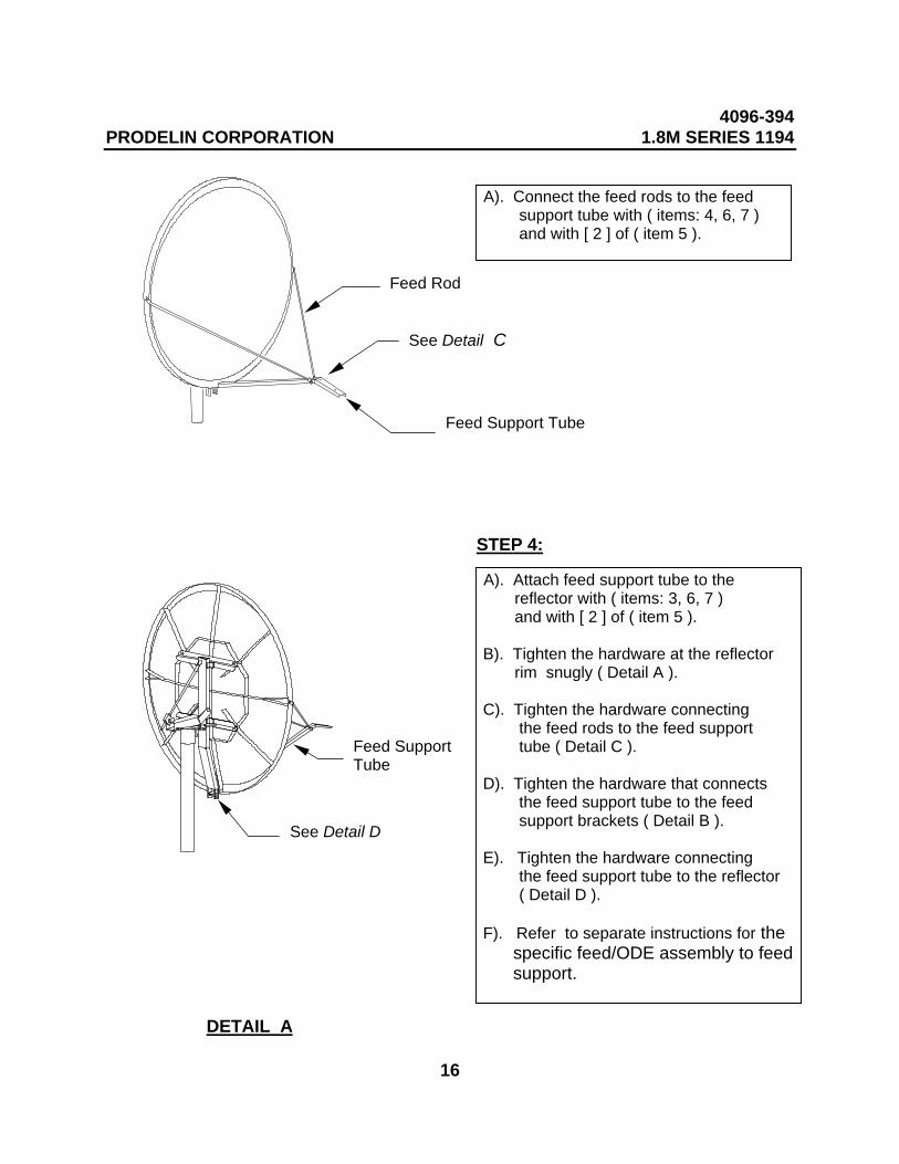
STEP 4:
A). Connect the feed rods to the feed support tube with ( items: 4, 6, 7 ) and with [ 2 ] of ( item 5 ).
See Detail C
Feed Rod
Feed Support Tube
A). Attach feed support tube to the reflector with ( items: 3, 6, 7 ) and with [ 2 ] of ( item 5 ).
B). Tighten the hardware at the reflector rim snugly ( Detail A ).
C). Tighten the hardware connecting the feed rods to the feed support tube ( Detail C ).
D). Tighten the hardware that connects the feed support tube to the feed support brackets ( Detail B ).
E). Tighten the hardware connecting the feed support tube to the reflector ( Detail D ).
F). Refer to separate instructions for the specific feed/ODE assembly to feed support.
See Detail D
DETAIL A
Feed SupportTube
4096-394PRODELIN CORPORATION 1.8M SERIES 1194
17
SECTION III ANTENNA POINTING
[ 7 ]
[ 5 ][ 5, 6, 7 ]
Reflector
Feed Rod
[ 5, 6, 7 ] Feed Support Tube
Feed SupportBrackets
[ 8 ]
[ 5, 6, 7 ]
DETAIL B
[ 4 ]
[ 5 ]
Feed Support Tube
[ 5, 6, 7 ]
Feed Rod
DETAIL C
DETAIL D
Reflector
[ 5 ]
[ 3 ]
[ 5, 6, 7 ]
Feed Support Tube
Feed SupportBracket
4096-394PRODELIN CORPORATION 1.8M SERIES 1194
18
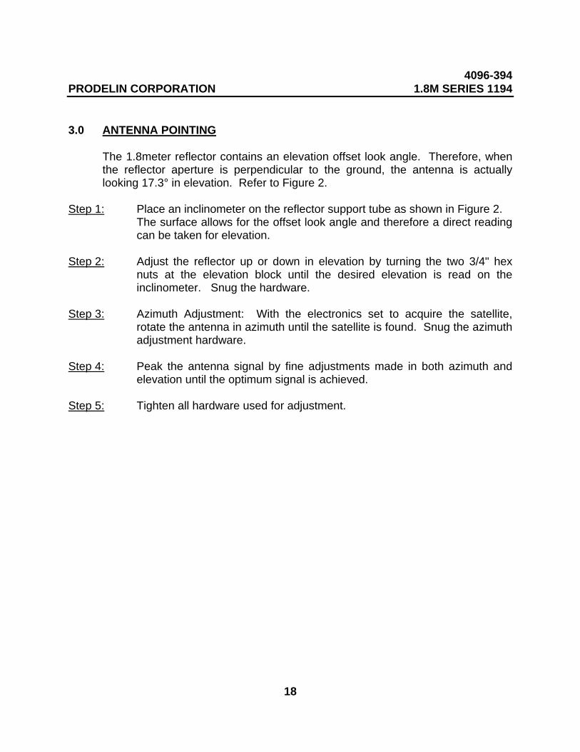
3.0 ANTENNA POINTING
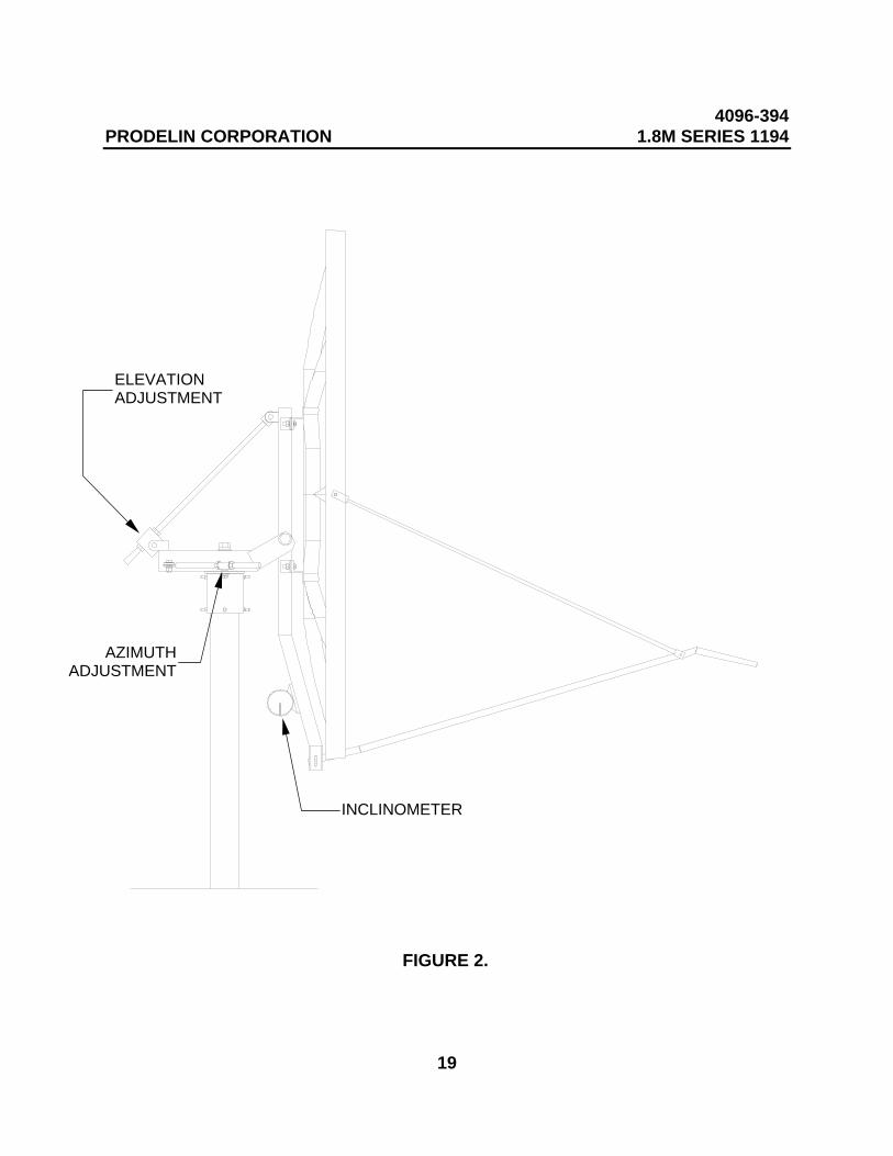
The 1.8meter reflector contains an elevation offset look angle. Therefore, whenthe reflector aperture is perpendicular to the ground, the antenna is actuallylooking 17.3° in elevation. Refer to Figure 2.
Step 1: Place an inclinometer on the reflector support tube as shown in Figure 2.The surface allows for the offset look angle and therefore a direct readingcan be taken for elevation.
Step 2: Adjust the reflector up or down in elevation by turning the two 3/4" hexnuts at the elevation block until the desired elevation is read on theinclinometer. Snug the hardware.
Step 3: Azimuth Adjustment: With the electronics set to acquire the satellite,rotate the antenna in azimuth until the satellite is found. Snug the azimuthadjustment hardware.
Step 4: Peak the antenna signal by fine adjustments made in both azimuth andelevation until the optimum signal is achieved.
Step 5: Tighten all hardware used for adjustment.
4096-394PRODELIN CORPORATION 1.8M SERIES 1194
19
FIGURE 2.
INCLINOMETER
AZIMUTHADJUSTMENT
ELEVATIONADJUSTMENT
4096-394PRODELIN CORPORATION 1.8M SERIES 1194
20
SECTION IV MAINTENANCE
4.0 MAINTENANCE OVERVIEW
After installation, the antenna requires only periodic inspection. It is anticipatedthat maintenance, if required, will be minimal and easily handled by a local or in-house maintenance staff. The materials used in the construction of this EarthStation Antenna virtually eliminate any maintenance repairs.
4.1 PERIODIC INSPECTION
It is suggested that a periodic inspection be performed at least every six months.
NOTE: After any very severe weather conditions, inspection of the antennashould be performed to determine if foreign objects have caused damageor if survival specifications have been exceeded.
This inspection should include the following:
1) Check all bolting locations - all bolts should be tight.
2) Check all structural members - repair or replace if damaged.
3) Check the foundation anchor bolts - they must be secure and with nofailure signs in foundation.
4) Check for corrosion - on the reflector structure and mount.
4.2 REFLECTOR
Prodelin's reflector does not require any maintenance. The compositeconstruction of the reflector is virtually impervious to any damages that could becaused by weather or other atmospheric conditions.
It is only necessary to inspect for any physical damage done by vandalism orvery severe weather conditions.
Should any damage be detected to a portion of the reflector, contact theCustomer Service Department at Prodelin for recommendations involvingreflector repair.
4096-394PRODELIN CORPORATION 1.8M SERIES 1194
21
4.3 MOUNT AND REFLECTOR SUPPORT STRUCTURE
The mount and reflector support structure supplied with this antenna is of steelconstruction and has a hot-dipped galvanized finish.
If inspection shows any signs of structural failure, the mount members that aredamaged should be repaired or replaced.
Corrosion: Any corrosion on steel members may be repaired with a cold, zinc-rich galvanizing paint.
4.4 FEED AND FEED SUPPORT
The feed support system should be inspected to insure that all hardware issecure. The feed/radio mounting bolts should be tight.
The feed horn window should be inspected to insure that it is intact so that nomoisture can collect inside the feed horn. Replace if damaged.