prodelin 4.5 meter is a precise, quality, state-of-the-art c or ku-band receive- only antenna. it...
TRANSCRIPT

CompressionMolded Centerfed Reflector
SummaryThe Prodelin 4.5 Meter is a precise, quality, state-of-the-art C or Ku-Band Receive-Only Antenna. It features a variety of mounts and a glass fiber reinforced galvanizedreflector which is powder coated for superior protection against the elements.
The 4.5 Meter Receive-Only reflector consists of 8 draw die formed contoured petalswith matched radial beams.This straightforward construction approach requires nofield alignment, significantly reducing installation time and cost. The Prodelin 4.5
Meter Prime Focus is one of the highest performance antennas in the industry dueto its sophisticated, precision SMC compression molding process technology.
. Low Transportation Cost with
..... Eight Panel Reflector
. Individual Panels Interchange-
.... able and Field Replaceable
. Fully Galvanized Steel Mounts ATCi provides the best value antenna solutions to market with competitive pricing,highest quality products and unmatched engineering support.
.. . AzlEI or Declination CorrectedPolar Mounts Applications
.. Optional Galvanized King PostAvailable
. Broadcasting
. Cable TV & Radio
. Corporate Business
. Government & Miltary
. Educational Institutions
www.atcI.com ~ ..... ATCiCorporate Ofce
450N McKemy . Chandler, AZ 85226
t 480.844.8501 . f 480.898.7667
Profit From Our Experience

ELECTRICAL Series 1451
C-Band4.5 M (15 ft.)3.625 - 4.242.9 dBi
Linear1.20
CPR 229-20 dB::30 dB (on axis)1.3: 1 Max.
Ku-Band4.5 M (15 ft.)10.95 -12.7552.6 dBi
Linear.420
WR75-20 dB::30 dB (on axis)1.3:1 Max
Antenna SizeOperating FrequencyMidband Gain (+1- .5 dB)Polarization3 dB BeamwidthFeed InterfaceFirst Sidelobe (Typical)Cross-Pol IsolationVSWR
MECHANICAL
Reflector Material
Antenna OpticsMast Pipe SizeElevation Adjustment RangeAzimuth Adjustment RangeShipping Specifications
Glass Fiber Reinforced Polyester SMCPrime Focus, 8 Piece Axisymmetric10" SCH 40 Pipe (10.75" 00) 27.30 em.50 to 900 Continuous Fine Adjustment (900 Optional)3600 ContinuousWeight: 9501bs. (428 kg.)
ENVIRONMENTAL PERFORMANCE
Wind LoadingOperationalSurvival
TemperatureOperationalSurvival
45 mph (72 km/h)125 mph (201 km/h)
-400 to 1400 F (-40 to 600 C)_500 to 1600 F (_46° to 710 C)
Atmospheric Conditions Salt, Pollutants and Contanimants as Encountered inCoastal and Industrial Areas.
Solar Radiation 360 BTU/h/ft
i'rillJìiìI§BltJ!l~l\il~~l~~~~;,~~~n~;lgtitGiiíit~n48~~S850JrQrCIt!'èl1t:liwiftS...
PRODELINNA TriPoint Global Company 4096-345
Revision G
December 18, 2002,
ASSEMBLY MANUAL
4.5 METER RxOANTENNA SYSTEM
PRODELIN CORPORATION1500 Prodelin DriveNewton NC 28658

PRODELIN CORPORATION4096-345
4.5 METER RxO ANTENNA SYSTEM
4.5 METER RxOANTENNA SYSTEM
G Revised part table pg 8 8037-064 to 8307-072 12/18/02 REM
F Revised parts table pg 8 8037-064 was 8037-056 11/11/02 REM
E Revised Address 1/11/02
D Revise 1-8 x 3.00 to 1-8 x 4.00 Page 8 1 0/04/01 RAH
C Revised and updated 11/16/98 RAH
B Revised parts list table pg. 11, 0211-700 was 0490-291. 07/17/97 PGWRevised pgs 10 & 12
A PIN 0176-225 WAS 0176-903 ON PG 24 PER ECN #1667 08/08/94 RF
- ORIGINAL ISSUE 03/29/94 K. NAGELSKI
REV. DESCRIPTION DATE APPROVED

PRODELIN CORPORATION4096-345
4.5 METER RxO ANTENNA SYSTEM
4.5 METER RxO ANTENNA SYSTEM
TABLE OF CONTENTS
SECTION TITLE
I
1.01.11.21.3
GENERAL INFORMATIONINTRODUCTIONUNPACKING AND INSPECTIONMECHANICAL INSTALLATION TOOLSSITE SELECTION
II
2.0SUGGESTED MAST AND FOUNDATION
PEDESTAL FOUNDATION
II3.03.1
Az/EL POSITIONER ASSEMBLYPART LISTAZ/EL POSITIONER INSTALLATION
IV
4.04.14.24.3
REFLECTOR ASSEMBLYP ART LISTREFLECTOR PRE. ASSEMBLYREFLECTOR ASSEMBLYREFLECTOR ALIGNMENT
V5.05.15.2
FEED ASSEMBLYFEED HORN ASSEMBLYFEED SUPPORT ASSEMBLYFEED INSTALLATION
VI
6.0ANTENNA POINTING
ANTENNA ALIGNMENT TO SATELLITE
VII
7.07.17.27.37.4
MAINTENANCEMAINTENANCE OVERVIEWPERIODIC INSPECTIONREFLECTORMOUNT & REFLECTOR SUPPORT STRUCTUREFEED & FEED SUPPORT

PRODELIN CORPORATION4096-345
4.5 METER RxO ANTENNA SYSTEM
2

PRODELIN CORPORATION4096-345
4.5 METER RxO ANTENNA SYSTEM
SECTION I GENERAL INFORMATION
1.0 INTRODUCTIONThis manual describes the assembly and installation of Prodelin's 4.5M RxOantenna system. The Prodelin 4.5M is a rugged, reliable antenna system that willoperate at C-band and Ku-band frequencies with high effciency and at the sametime successfully withstand the effects of the environment.
These instructions are listed by sections that cover all areas of assembly andinstallation. Additional sections are included in the manual to provide informationon antenna alignment to the satellte and maintenance.
1.1 UNPACKING AND INSPECTION
1. UNPACKING & INSPECTION - The antenna containers should beunpacked and inspected at the earliest date to ensure that all material hasbeen received and is in good condition. A complete packing list for eachmajor component is supplied.
2. FREIGHT DAMAGE - Any damage to materials while in transit should beimmediately directed to the freight carrier. He will instruct you on thematters regarding any freight damage claims.
3. MATERIAL - MISSING OR DAMAGED - Any questions regarding missingor damaged materials that is not due to freight carrier should be directedto Prodelin's Customer Service Department at:
PRODELIN CORPORATION1500 Prodelin Drive
Newton NC 28658USA
(828) 464-4141
3
PRODELIN CORPORATION4096-345
4.5 METER RxO ANTENNA SYSTEM
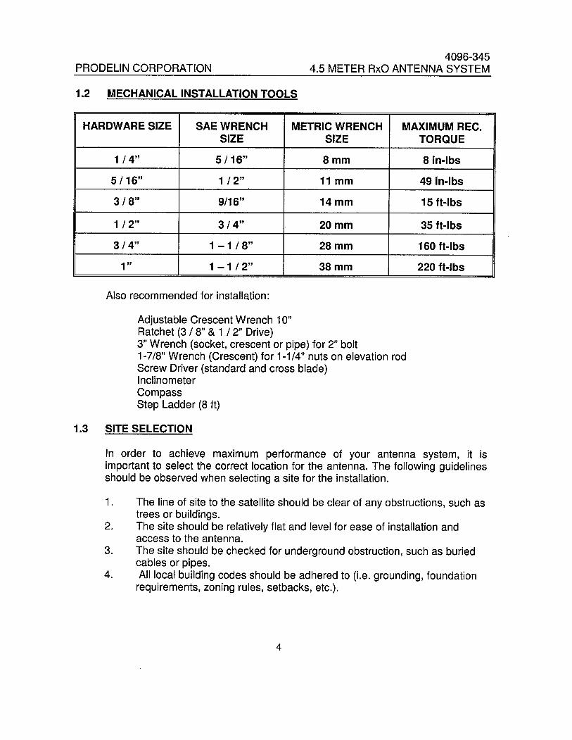
1.2 MECHANICAL INSTALLATION TOOLS
HARDWARE SIZE SAE WRENCH METRIC WRENCH MAXIMUM REC.SIZE SIZE TORQUE
1 / 4" 5/16" 8mm 8 in-Ibs
5 / 16" 1 / 2" 11 mm 49 in-Ibs
3 / 8" 9/16" 14mm 15 ft-Ibs
1 / 2" 3/4" 20mm 35 ft-Ibs
3/4" 1 - 1 / 8" 28mm 160 ft-Ibs
1 " 1 - 1 / 2" 38mm 220 ft-Ibs
Also recommended for installation:
Adjustable Crescent Wrench 10"Ratchet (3 / 8" & 1 / 2" Drive)3" Wrench (socket, crescent or pipe) for 2" bolt1-7/8" Wrench (Crescent) for 1-1/4" nuts on elevation rodScrew Driver (standard and cross blade)InclinometerCompassStep Ladder (8 ft)
1.3 SITE SELECTION
In order to achieve maximum performance of your antenna system, it isimportant to select the correct location for the antenna. The following guidelinesshould be observed when selecting a site for the installation.
1. The line of site to the satellte should be clear of any obstructions, such astrees or buildings.
2. The site should be relatively flat and level for ease of installation andaccess to the antenna.
3. The site should be checked for underground obstruction, such as buried
cables or pipes.4. All local building codes should be adhered to (Le. grounding, foundation
requirements, zoning rules, setbacks, etc.).
4

PRODELIN CORPORATION4096-345
4.5 METER RxO ANTENNA SYSTEM
SECTION II SUGGESTED MAST AND FOUNDATIONS
NOTE: Due to the wide variety of soil conditions, Prodelin Corporation does not warrant thatany particular design or size of foundation is appropriate for any locality or earth stationinstallation. It is the responsibilty of the installer/user to determine if it meets the site/localityrequirements. If there is any doubt, have it checked by an architect or structural engineer.
2.0 PEDESTAL FOUNDATION
Figure 1 shows a suggested Pad Foundation and figure 2 shows a suggestedPier Foundation. Both foundations utilize Prodelin' s Pedestal Mount. To installthe Pedestal Mount foundation, follow the steps below.
1. Install one (1)1 V2" -6 hex nut and one (1) 1 V2" flat washer (items 2,3) onto the
anchor rod (item 5), then insert the anchor rod into one of the holes in theplywood template (item 6) and install another 1 V2" -6 hex nut and 1 V2 "flatwasher. Repeat this procedure for the remaining anchor rods. This will keepall the anchor rods in the straight and proper orientation when the concrete ispoured. Next, install two (2) 1-8 hex nuts and one (1) flatwasher (items 2,3) onthe other end of each anchor rod. See following pad layout and figures 1 & 2.
2. Once the site location is determined, dig up the area where the foundation wil beinstalled. Be careful not to dig too deep because the soil in the bottom and sidesof the foundation should be undisturbed. Position the reinforcing bars as shown.Position the anchor rods so that the flatwashers are positioned under the
reinforcing bars. Pour concrete and allow it to dry for 24 hours.
3. Once the concrete is dry, remove the plywood template and screw the lower hex
nuts as far down on the anchor rods as possible. Then install the mast pipe(item 1) on to the anchor rods. Adjust the lower hex nuts until the mast pipe islevel in the vertical position. Reinstall the flatwashers, lockwashers and hex nuts.With the mast pipe tightened down, fil the space between the concrete slab andthe mast pipe base with grout.
NOTES:1. ALL CONCRETE SHOULD CONFORM TO BUILDING CODE STANDARDS AND HAVE A MINIMUM
COMPRESSIVE STRENGTH OF 3000 PSI AT 28 DAYS. (PER ACI-318-77)2. SOIL BEARING CAPACITY SHOULD BE NO LESS THAN 2000 PSF.3. CONCRETE SHOULD BE POURED AGAINST UNDISTURBED SOIL4. ALLOW CONCRETE 24 HOUR SET TIME BEFORE INSTALLATION OF ANTENNA.5. THE ANTENNA SHOULD BE PROPERLY GROUNDED TO MEET APPLICABLE LOCAL CODES.6. MINIMUM DEPTH AS SHOWN OR EXTENDED TO LOCAL FROST LINE.
(PRODELIN CORP. DOES NOT REPRESENT OR WARRANT THAT ANY PARTICULAR DESIGN ORSIZE OF FOUNDATION IS APPROPRIATE FOR ANY LOCALITY OR EARTH STATION INSTALLATION.)
5
PRODELIN CORPORATION4096-345
4.5 METER RxO ANTENNA SYSTEM
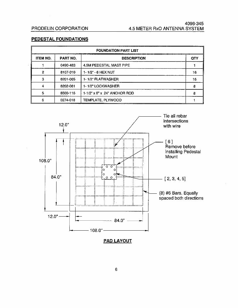
PEDESTAL FOUNDATIONS
IFOUNDATION PART LIST
I
ITEM NO. PART NO. DESCRIPTION QTY
1 0490-483 4.5M PEDESTAL MAST PIPE 1
2 8107-010 1- 1/2" - 6 HEX NUT 16
3 8201-065 1- 1/2" FLATWASHER 16
4 8202-061 1- 1/2" LOCKWASHER 8
5 8500-116 1-1/2" x 6" x 24" ANCHOR ROD 8
6 0274-018 TEMPLATE, PLYWOOD 1
12.0"
108.0"
84.0"
Tie all rebarintersectionswith wire
.______h__________________.__n.._........n_nn___._ .hO__._______________.___.~n_----_...........-..-'.hh-._--_..._--___-_-....----_- __,...._______..._______...,." " " " .. " .. .," .. .. " .. .. .. .... .. " " " " " "" .. .. " " " " .." " .. " " " " .... " " " .. .. .. .." " " " " .. .. .." " " " . .. " "" " .. " I " .. ..¡ F=:::::::: :f¡:::::: ::::H ::::::::: :F~::::: :::: ~~:: :::::::: H::: ::: ::::f¡: ::::::::: j;" " " " " .. " ," .. " .. .. " " "" .. " ,. .. " .. "" .. " " " " " "" .. " " " " " "" " " I. .. .. " "" .. " " .." ".. " " " " " . ".. " " " " " " ". ~. hU. _ __AU. h _ un _ _~. n___ __ _ nL" _ _ __. _ _w_ .,0.. _ _ _ _ _ n. ...... _ .h .U.. _ _ _ ___ _.~,. ~ n__... h...... _ hO. _ _~. _ n_ _ __ _ _ _... _ _". _ _n _ ..~_. _ _ _ _ __.. H no . _.. .... h. _ __ _ _ _~," " " .. " " .. .... " .. " ., " " "" " " "" ".." " .. "" ...... " " "ii """ .. " "" """ " " "" """ "" """¡r"''''''''~''''''''''if:'':::: .~. 0 0 .~' """'ir"""''''~''''''''''1¡" .." ",,"" "" """:: ¡¡ ¡¡ 0 0 :: :: ::¡r"""''''M''''''''''j!''''''''''.. 0 0..' """'n".......'~"""""!¡.. ".. ..".... ..".." ..".... ..""" """" ...."" "".. " " " " " " ".~... _ _ _ _ n _~_ _ _ _ n _ __ _.. __ _ _ _ __"" ....".. _"... _ ..~... n.""".. ~_ _ _ _ _ _ _ _" _.._ _" __...""... ~......... ........ _ n_ _~. n _ _ _ _ _ _ _ _ .~_" _ _" _... .".. _n.."... ~........ n~. _. un _ _ _"" .. " " " " " "" II ,. " .. " " "" " " " .. " " "" " " " " " " "" II " " .. " " ." " " " " " " "., " " " " .. " "" II " II .. .. II "" .. " " " " " "" " " II " II " "'t::::;:::::O::::::::::)J::::::::::CO:::::::::::O):;::::::::ic:::::;::::O::::::::::)'.. " " " " " " .." " " " II .. .. "" " .. " " .. " .... ...."""".. "" II " " .... """"""" ..".." 0' "" """........ """,,"".. " " " " " " "...._..n n_" "~"........."...n _. _ _ _... n _ _ _ ____ ...._ n n..""...... ....... .....n...."...n_ _ n_ _...."". _......... _........ _ _ _ _ _ _ _ _ _n ___ _ ____........... _.............. _. _.
( 6 )Remove beforeinstallng PedestalMount
( 2, 3, 4, 5)
(8) #6 Bars. Equallyspaced both directions
12.0" -- L
L-108.0" . .I
84.0"
PAD LAYOUT
6

PRODELIN CORPORATION4096-345
4.5 METER RxO ANTENNA SYSTEM
1-1/2" Grout Leveling \
(if required)
4.0"
i- ':~'::' .o'~' ::: .;.:.: ':. :,',. :'. ..: ..: . .o§:: '.0'.: '0;: . .: .0..::. ~ :.f~
r i.. ° 0'. '.' , . ., . . , ...0.... . '. 0'.' , ° '.24 0" . 0' . . . . . 0' . ö. . . . '" .,.'. . '. "0.210" 0. "0 . ...0..0,...... ..
4= :.o~~:.;:i;:: ::..(o;:r~ ~. :~ .~ ";?;\;oj.;?~:..!r;.~~" .. .. 0.. "" o. ." 0".. .." .. ...... .. .. ... ,,0" "
3.0" MIN (TYP)Fiaure 1
( 1 J
( 5)1-1/2" Grout Leveling(if required) ( 2, 3, 4 )
(2,3)
4.0".. .. " .... 0" "" 0'
0"0.00 å "0,, .. ". . °".. 0°.. DO" 0,,°0°".. ..
.. .0. 0 " 000. .. .... .... .. "0".. ö ........ .. ö"." ..
(8) #8 Bars. Equallyspaced both directions
144.0".." "" 0" .. .." 0 o. .." .0. 0 0".. ".. 0.. 0 0
..0.'0 .0'. °
" °0,," 0 0 0"0 0" ..
,," ..0" o. .. "0..
0." ..0 " .. : 0 (10) #3 Ties (§ 14"center to center
.. 0"".0 0" o.
o .. .. 0 0.. ".0
.. .. .. 0:.. "0 0°": 0 ~ 0 o. ?,," 0. .. 3000 PSI Concrete".." 0 .. o. ..
L36" DIAJFigure 2
7

PRODELIN CORPORATION4096-345
4.5 METER RxO ANTENNA SYSTEM
SECTION II Az/EL POSITIONER ASSEMBLY
Az/EL POSITIONER ASSEMBLY PART LIST - TABLE 3.0
ITEM NO. PART NO. DESCRIPTION QTY
1 0490-480 POSITIONER ASSEMBL Y- AZIMUTH 1
2 8036-032 1-8 x 4.00" HEX BOLT 4
3 8201-049 1" FLATWASHER 12
4 8202-046 1" LOCKWASHER 4
5 8107-007 1" HEX NUT 6
6 8037-072 2-4.5 x 9.00" HEX BOLT 1
7 8201-050 2' FLATWASHER 1
8 0490-477 AZIMUTH ADJUSTMENT ROD 1
9 0211-700 AZIMUTH TUBE WELMENT 1
10 8035-016 3/4" -10 x 2.00" HEX BOLT 5
11 8201-045 3/4" FLATWASHER 5
12 8202-045 3/4" LOCKWASHER 5
13 8030-010 1/4" - 20 x 1.25" HEX BOLT 1
14 8201-040 1/4" FLATWASHER 2
15 8202-040 1/4" LOCKWASHER 1
16 8100-007 1/4" HEX NUT 1
17 0181-377 ELEVATION I HUB WELDMENT ASSEMBLY 1
18 8403-011 U-BOL T, 5/8"- 11 UNC 2
19 8105-007 5/8" HEX NUT 8
20 8201-044 5/8" FLATWASHER 4
21 0168-127 ELEVATION BLOCK 2
22 0180-284 ELEVATION ADJUSTMENT SCREW 1
23 81 09-006 1-114" HEX NUT 4
24 8201-048 1-1/4" FLATWASHER 4
8

PRODELIN CORPORATION4096-345
4.5 METER RxO ANTENNA SYSTEM
3.1 Az/EI POSITIONER INSTALLATION
Toward DesiredAzimuth Heading
STEP 1:
A) Properly orient the positioner assembly(item 1) onto the pedestaL.
B) Rotate the positioner assembly towardsthe desired azimuth heading as shown.
C) Once the position is located, rotate thepositioner in either direction to thenearest set of holes that line up withthe ring slots. The result is a coarseazimuth setting (+/- 30 deg.). Thefine azimuth setting wil be set later.
( 3, 4, 5 )
'- Pedestal
D) Secure the positioner in four places tothe pedestal with 1" hardware (items 2,3,4,5).
~~ (6,7)~
)"
-,'".." Hole
STEP 2:
Install the 2" hardware (items 6, 7) throughthe center hole of the positioner into thepedestal threaded hole.
9
PRODELIN CORPORATION4096-345
4.5 METER RxO ANTENNA SYSTEM
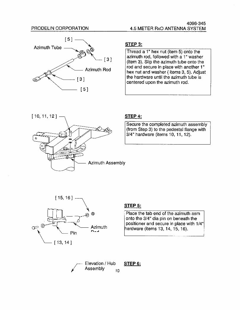
r 5 )
Azimuth Tube ~ ~
/~~ (31
Azimuth Rod~(31r 5 )
r 10, 11, 12 )
Azimuth Assembly
(15, 16) \
. _~__.( ~~ (9~ '- '- Azimuth
~ ! 13, 14 ~in n__
STEP 3:
Thread a 1" hex nut (item 5) onto theazimuth rod, followed with a 1" washer(item 3). Slip the azimuth tube onto therod and secure in place with another 1"hex nut and washer ( items 3, 5). Adjustthe hardware until the azimuth tube iscentered upon the azimuth rod.
STEP 4:
Secure the completed azimuth assembly(from Step 3) to the pedestal flange with3/4" hardware (items 10, 11, 12).
STEP 5:
Place the tab end of the azimuth asmonto the 3/4" dia pin on beneath thepositioner and secure in place with 1/4"hardware (items 13, 14, 15, 16).
r Elevation / Hub STEP 6:Assembly 10

PRODELIN CORPORATION4096-345
4.5 METER RxO ANTENNA SYSTEM
( 18 i 2 PL.
( 19, 20 i
~ (23, 24 i 4 PL.
( 21 i
r ( 10, 11, 12 i~ ~~".
( 1 0, 11, 12 i
Elevation Block Assembly
SECTION IV
Place the elevation I hub assembly(item 17) onto the cradles on thepositioner assembly and secure with(2) U-bolts and 5/8" hardware ( items18, 19, 20). Note that each leg of theU-bolts requires ( 2 ) 5/8" hex nuts.
STEP 7:
A) Thread a 1-1/4" hex nut (item 23) onto the elevation rod (item 22), followed
with a 1-1/4" flatwasher(item 24).
B) Slip a elevation block (item 21) ontothe elevation rod and secure in placewith another 1-1/4" hex nut and washer.
C) Repeat the same procedure for thesecond elevation block.
STEP 8:
A) Install the elevation block assemblyin-between the clevis tabs on theelevation I hub and the positioner.Secure both blocks in place with 3/4"hardware (items 10, 11, 12).
B) By adjusting the 1-1/4" nuts on theelevation rod, Adjust the rod so thatthe elevation I hub assembly is at a 90deg. elevation angle.
C) Tighten all fasteners securely.
REFLECTOR ASSEMBLY
11

PRODELIN CORPORATION4096-345
4.5 METER RxO ANTENNA SYSTEM
REFLECTOR ASSEMBLY - TABLE 4.0
ITEM NO. PART NO. DESCRIPTION QTY
1 0181-362 REFLECTOR PETAL (WITH HOLE) 4
2 0181-374 REFLECTOR PETAL 4
3 0217-073 FEED SUPPORT CLEVIS 4
4 0413-123 RIB 8
5 0211-585 RIB CLIP 8
6 0156-063 PLATE, CENTER HOLE 1
7 0225-539 CLIP, CENTER HOLE 1
8 0211-586 CLIP, HUB 8
9 8304-004 8 - 32 X 1.5" SCREW 6
10 8112-003 8 - 32 HEX NUT 6
11 8201-043 1/2" FLATWASHER 8
12 8202-043 1/2" LOCKWASHER 4
13 8104-007 1/2" HEX NUT 8
14 8202-010 3/8" - 16 x 1.25 HEX BOLT 96
15 8201-042 3/8"FLATWASHER 192
16 8202-042 3/8" LOCKWASHER 96
17 8102-007 3/8" HEX NUT 96
12

PRODELIN CORPORATION4096-345
4.5 METER RxO ANTENNA SYSTEM
4.1 REFLECTOR PRE-ASSEMBLY
The reflector consists of eight interchangeable petals of compression moldedglass-fiber reinforced materiaL. This material is very strong, yet lightweight andeasy to handle. The reflector wil possess a very accurate parabolic shape whenproperly assembled and wil retain it's shape for years under harshenvironmental conditions. The microwave reflective surface is provided by a finemesh screen that lies just beneath the molded surface of the petals.
'-r 1 )
A) Identify the reflector petals and parts ofthe reflector support structure accordingto the parts list.
B) Note that four of the petals (item 1) havea 1 12" hole thru the center. These holesare for the feed support clevis pins.Pre-assemble these reflector petals asfollows.
C) Run the 1 I 2" nut (item 13) up the threadsof the clevis (item 3), and place a 1 12"flatwasher (item 11) against the nut. Adjustthe nut until the distance from the far sideof the washer and the center of the clevishole is 1 .5" .
D) From the face of the petal, insert the clevisassembly thru the hole in the center of thepetal. Secure with 1 12" hardware. Tighten
these nuts only hand tight at this time.
13
PRODELIN CORPORATION4096-345
4.5 METER RxO ANTENNA SYSTEM
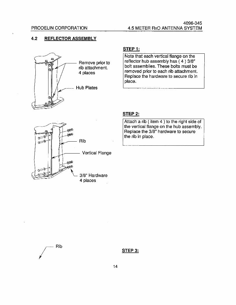
4.2 REFLECTOR ASSEMBLY
Remove prior torib attachment.4 places
Hub Plates
Rib
Vertical Flange
..._.~~(9
~'i(9
..' '- 3/8" Hardware4 places
rRib
STEP 1:
Note that each vertical flange on thereflector hub assembly has ( 4 ) 3/8"bolt assemblies. These bolts must beremoved prior to each rib attachment.Replace the hardware to secure rib inplace.
STEP 2:
Attach a rib ( item 4 ) to the right side ofthe vertical flange on the hub assembly.Replace the 3/8" hardware to securethe rib in place.
STEP 3:
14

PRODELIN CORPORATION4096-345
4.5 METER RxO ANTENNA SYSTEM
A) Secure the flange of the rib to therib clip at the base of the hub with3/8" hardware (items14, 15, 16, 17)
( 15, 16, 17 J
~11,- (14,15 J
B) Repeat the above procedures foreach of the remaining ribs.
Clip
STEP 4:
A) Select a petal without a feed clevis( item 2 ) and locate it so that its centerline wil be in a vertical position on theassembled reflector.See detail A.
B) Place the panel on top of the ribs sothat the petal flanges are to the left ofthe corresponding rib webs (as viewedfrom the back of reflector).
Detail A
C) Temporarily install (2) 3/8" bolts(item 14) through the outermost ribhole and the mating petal flange hole.
~ Temporally install 3/8" bolt (item 14) here./ 15

PRODELIN CORPORATION4096-345
4.5 METER RxO ANTENNA SYSTEM
Rib ( on inside of petal flange)
Petal (w/out clevis)
'- Rib (outside p~tal flange)
Temporally install 318" bolt (item 14) here.
STEP 5:
A) Select a petal with a clevis ( item 1)and place it next to the petal installedon the previous step. Orient the petalflanges the same as in previous step.
B) Remove temporary 3/8" bolt wherethe petal flanges meet.
C) Align the petal flanges and rib holesand secure at the outermost rib holewith 3/8" hardware (items 14,15,16,17).Do Not Tiqhten.
16

PRODELIN CORPORATION4096-345
4.5 METER RxO ANTENNA SYSTEM
( 14, 15, 16, 17)This hole only
( 1 ) Petal with clevis
See Steo 6
( 2)
STEP 6:Petal Web
Remove the existing 318" hardwarefrom the petal web hole as shown.
Rib (between the two petals)
Remove 3/8"Hardware
17
PRODELIN CORPORATION4096-345
4.5 METER RxO ANTENNA SYSTEM
( 15, 16, 17)
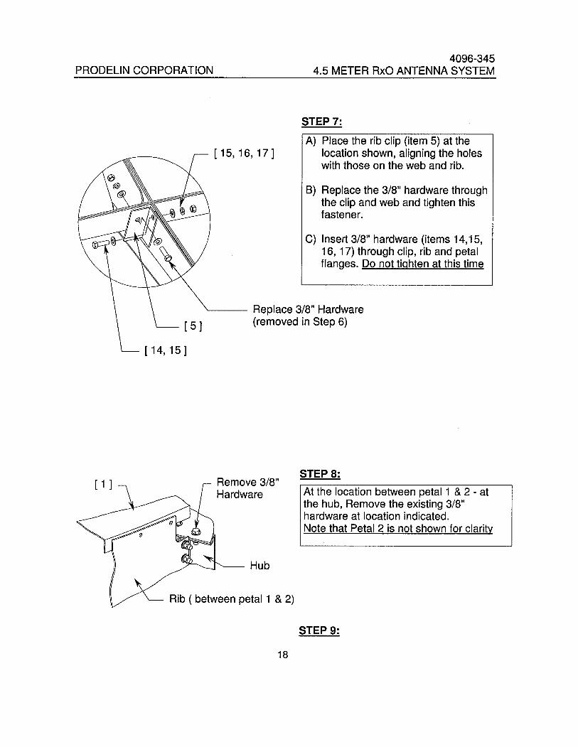
STEP 7:
A) Place the rib clip (item 5) at thelocation shown, aligning the holeswith those on the web and rib.
B) Replace the 3/8" hardware throughthe clip and web and tighten thisfastener.
C) Insert 3/8" hardware (items 14,15,16, 17) through clip, rib and petalflanges. Do not tiahten at this time
Replace 3/8" Hardware(removed in Step 6)
STEP 8:
At the location between petal 1 & 2 - atthe hub, Remove the existing 3/8"hardware at location indicated.Note that Petal 2 is not shown for clarity
Hub
Rib ( between petal 1 & 2)
STEP 9:
18

PRODELIN CORPORATION4096-345
4.5 METER RxO ANTENNA SYSTEM
3/8" Hardware ~
fl~
,','J
Place the hub clip (item 8) as shownand replace the 3/8" hardware tosecure the clip in place. Do not tiahten
( 1 )
STEP 10:
Now place 3/8" hardware (items 14, 15,16, 17 ) in the (7) remaining holes atthis petal to rib joint. Do not tiahten
( 2)
r 14, 15 J ( 15, 16, 17)
(9) \ISTEP 11 :
A) Select and install the remaining petalsusing the steps 5 through 10 above. Besure to locate the feed clevis petals(item 1) in their proper location.
CI, '-(10)L (7)
B) After all the ribs are in place, install thecenter hole plate (item 6) and the clips(item 7) at the center hole of the ribs.Secure clips in place with #8 hardware(items 9, 10). Do not tiahten.Petal
4.3 REFLECTOR ALIGNMENT
19

PRODELIN CORPORATION4096-345
4.5 METER RxO ANTENNA SYSTEM
1. Tighten (8) fasteners at the outermost holes in the petals.
2. Use a thin cord across the reflector diameter from rim to rim - at fourplaces. One end of each string should be taped to the rim just to one sideof the seam between two petals. The other end should be fastened 180degrees opposite. All four strings should lightly touch where they cross atthe center. The distance from the center of the reflector (cover to plate) tothe strings should be 37.5".
3. If the reflector does not check out as described above within
approximately 1/4", then reflector adjustment must be done. Identify thepoint on the rim that is either high or low. Gently push or pull on thereflector rim until it is brought into position. While the other installer holdsthe rim, the other installer should tighten all the flange bolts fully. Repeatthis process as required. Tighten all reflector fasteners at this time.
SECTION V FEED HORN ASSEMBLY
20
PRODELIN CORPORATION4096-345
4.5 METER RxO ANTENNA SYSTEM
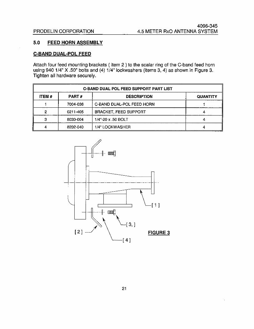
5.0 FEED HORN ASSEMBLY
C-BAND DUAL-POL FEED
Attach four feed mounting brackets ( item 2 ) to the scalar ring of the C-band feed hornusing 940 1/4" X .50" bolts and (4) 1/4" lockwashers (items 3,4) as shown in Figure 3.Tighten all hardware securely.
C-SAND DUAL POL FEED SUPPORT PART LIST
ITEM # PART # DESCRIPTION QUANTITY
1 7004-036 C-BAND DUAL-POL FEED HORN 1
2 0211-405 BRACKET, FEED SUPPORT 4
3 8030-004 1/4"-20 x .50 BOLT 4
4 8202-040 1/4" LOCKWASHER 4
-l+ mi
~!1i
( 2 )
( 4 )
FIGURE 3
21

PRODELIN CORPORATION4096-345
4.5 METER RxO ANTENNA SYSTEM
Ku-BAND DUAL - POL FEED
Remove outer most (4) #6 Phillips head screws. Position the mounting plate (item 2)over the waveguide flanges until it is flush with the backside of the scalar ring as shownin Figure 4. Re-install the (4) Philip head screws. Attach (4) feed mounting brackets tothe mounting plate with 1/4" hardware (items 4, 5, 6).
Ku-BAND DUAL POL FEED- PARTS LIST
ITEM # PART # DESCRIPTION QUANTITY
1 7004-035 Ku-BAND DUAL - POL FEED 1
2 0156-078 PLATE, MOUNTING 1
3 0211-405 BRACKET, FEED SUPPORT 4
4 8030-004 1/4"-20 x .50 BOLT 4
5 8202-040 1/4" LOCKWASHER 4
6 8100-007 1/4" HEX NUT 4
~- t:+~#6 Phillps head screws
141~ '-(1)
( 2 )-~\~(6J
L(5JFIGURE 4
22

PRODELIN CORPORATION4096-345
4.5 METER RxO ANTENNA SYSTEM
C/Ku-BAND 4-PORT FEED
Attach (4) feed mounting brackets (item 2) to the scalar ring of the C/Ku-Band feed hornusing 1/4" hardware ( items 3,4,5) - See Figure 5. Tighten securely.
BAND - PARTS LIST
ITEM # PART # DESCRIPTION QUANTITY
1 VARIOUS C/Ku-BAND DUAL - POL FEED HORN 1
2 0211-405 FEED SUPPORT BRACKET 4
3 8030-004 1/4"-20 x .50 BOLT 4
4 8201-040 1/4" FLATWASHER 4
5 8100-007 1/4-20 HEX NUT 4
~ -- --- - - --l-Q
( 1 L ~ --- - - --------
(21JFIGURE 5
23

PRODELIN CORPORATION4096-345
4.5 METER RxO ANTENNA SYSTEM
5.1 FEED SUPPORT ASSEMBLY
FEED SYSTEM PARTS liST
ITEM NO. PART NO. DESCRIPTION QUANTITY
1 VARIES FEED HORN ASSEMBLY 1
2 0176-225 FEED SUPPORT ROD 4
3 8031-008 3/8-16 x 1.00 BOLT 8
4 8201-042 3/8" FLATWASHER 16
5 8202-042 3/8" LOCKW ASHER 8
6 8102-007 3/8" HEX NUT 8
STEP 1:
Attach each of the feed support rods(item 2) to the feed support clevis with3/8" hardware (items 3,4,5,6).
Note that each rod should be attachedto the same side of the clevis - (insideor outside).
24
PRODELIN CORPORATION4096-345
4.5 METER RxO ANTENNA SYSTEM
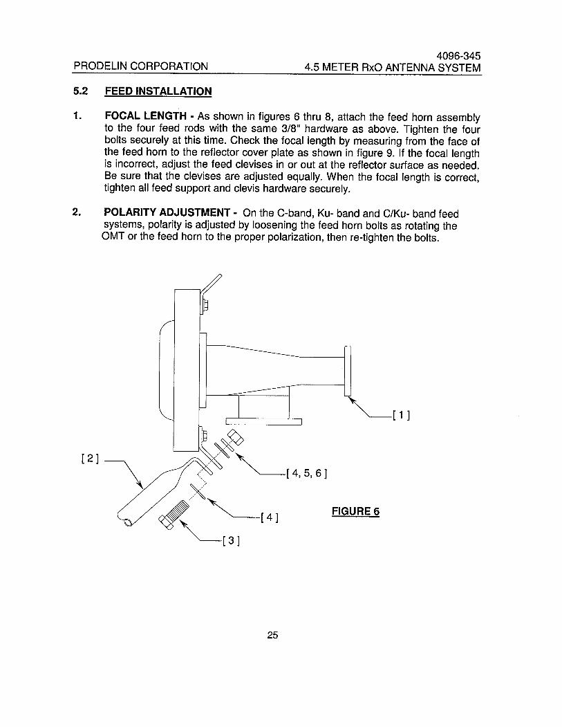
5.2 FEED INSTALLATION
1. FOCAL LENGTH - As shown in figures 6 thru 8, attach the feed horn assemblyto the four feed rods with the same 3/8" hardware as above. Tighten the fourbolts securely at this time. Check the focal length by measuring from the face ofthe feed horn to the reflector cover plate as shown in figure 9. If the focal lengthis incorrect, adjust the feed clevises in or out at the reflector surface as needed.Be sure that the clevises are adjusted equally. When the focal length is correct,tighten all feed support and clevis hardware securely.
2. POLARITY ADJUSTMENT - On the C-band, Ku- band and C/Ku- band feedsystems, polarity is adjusted by loosening the feed horn bolts as rotating theOMT or the feed horn to the proper polarization, then re-tighten the bolts.
(2)\( 1 L
FIGURE 6
25

PRODELIN CORPORATION4096-345
4.5 METER RxO ANTENNA SYSTEM
/1)( 1 J
FIGURE 8
Focal Length
FIGURE 9
26

PRODELIN CORPORATION4096-345
4.5 METER RxO ANTENNA SYSTEM
SECTION VI ANTENNA POINTING
6.0 ANTENNA ALIGNMENT TO SATELLITE
1. Set the elevation angle by rotating the 1-1/4" nuts on the elevation adjustment
rod. Measure the angle by placing an inclinometer on the reflector hub. See Fig.10.
2. The correct elevation angle is set, rotate the antenna in azimuth by removing the1" hardware (4 places) in the positioner plate. See Fig 10;
3. At this time, rotate the antenna in azimuth by turning the 1" nuts located on the
azimuth adjustment rod. Rotate in azimuth until a signal is reached.
4. Peak the antenna by fine adjustments made in both elevation and azimuth.
5. Adjust polarization by rotating the feed assembly in its mounting bracket.
6. Re-install the 1" hardware and the Az/EI positioner (from step #2) and tighten all
adjustment hardware securely.
27

PRODELIN CORPORATION4096-345
4.5 METER RxO ANTENNA SYSTEM
Inclinometer
ElevationAdjustment
Azimuth Adjustment
FIGURE 10
28

PRODELIN CORPORATION4096-345
4.5 METER RxO ANTENNA SYSTEM
SECTION VII MAINTENANCE
7.0 MAINTENANCE OVERVIEW
After installation, the antenna requires only periodic inspection. It is anticipatedthat maintenance, if required, will be minimal and easily handled by a local or inhouse maintenance staff. The materials used in the construction of this EarthStation Antenna virtually eliminate any maintenance repairs.
7.1 PERIODIC INSPECTION
It is suggested that a periodic inspection be performed at least every six months.
NOTE: After any very severe weather condition, inspection of the antenna shouldbe penormed to determine if foreign objects have caused damage or ifsurvival specifications have been exceeded.
This inspection should include the following:
1 : Check all bolting locations - all bolts should be tight.
2: Check all structural members - repair or replace if damaged.
3: Check the foundation anchor bolts - they must be secure and have no failuresigns in the foundation.
4: Check for corrosion - on the reflector structure and the mount.
7.2 REFLECTOR
Prodelin' s reflector does not require any maintenance. The composite construction ofthe reflector is virtually impervious to any damages that could be caused by weather orother atmospheric conditions.
It is only necessary to inspect for any physical damage done by vandalism orvery severe weather conditions.
Should any damage be detected to a portion of the reflector, contact theCustomer Service Department at Prodelin for recommendation involving reflectorrepair.
29

PRODELIN CORPORATION4096-345
4.5 METER RxO ANTENNA SYSTEM
7.3 MOUNT AND REFLECTOR SUPPORT STRUCTURE
The mount and reflector support structure supplied with this antenna is of steelconstruction and has a galvanized finish with zinc wlultraguard finish forhardware.
If inspection shows any sign of structural failure, the mount members that aredamaged should be repaired or replaced.
Corrosion: Any corrosion on steel members may be repaired with a zinc richgalvanizing paint.
7.4 FEED AND FEED SUPPORT
The feed support tube and feed rods should be inspected to insure that allhardware is secure. The feed and radio mounting bolts should be tight.
The feed horn window should be inspected to insure that it is intact so that nomoisture can collect inside the feed
30