disassembly and assembly - justanswerww2.justanswer.com/uploads/ke/kennyz1963/2013-04... ·...
TRANSCRIPT

307-01-1 307-01-1Automatic Transaxle/Transmission
DISASSEMBLY AND ASSEMBLYSpecial Tool(s)Transaxle
Test Plate Screw Set,TransmissionSpecial Tool(s)307-126 (T82P-7006-C)
Dial Indicator Gauge WithHolding Fixture100-002 (TOOL-4201-C)
Air Test Plate, Transmission307-313 (T94P-77001-EH)
Step Plate205-D014 (D80L-630-3)
Gasket, Transmission Air TestPlate307-313 (T94P-77001-EH1)
Installer, Steering Gear PinionBearing211-161 (T90C-3504-DH)
Installer, Halfshaft Output FluidSeal307-157 (T86P-1177-B)
Depth Micrometer303-D075 (D92P-4201-A)
Gauge, Servo Rod307-162 (T86P-70023-B)
Retaining Ring Pliers307-343 (T95P-77001-AHR)
Holding Fixture Transmission307-003 (T57L-500-B)
Handle, Torque Converter307-091 (T81P-7902-C)
Lifting Fixture, Clutch Pack307-171 (T86P-70389-A)
(Continued)
(Continued)
Copyright 2004, Ford Motor CompanyLast updated: 6/4/2008 2005 Freestar, Monterey, 7/2004
307-01-2 307-01-2Automatic Transaxle/Transmission
DISASSEMBLY AND ASSEMBLY (Continued)
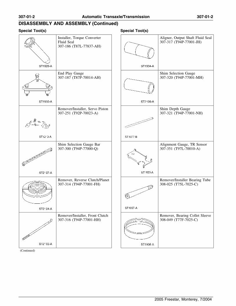
Special Tool(s) Special Tool(s)
Installer, Torque Converter Aligner, Output Shaft Fluid SealFluid Seal 307-317 (T94P-77001-JH)307-186 (T87L-77837-AH)
End Play Gauge Shim Selection Gauge307-187 (T87P-70014-AH) 307-320 (T94P-77001-MH)
Remover/Installer, Servo Piston Shim Depth Gauge307-251 (T92P-70023-A) 307-321 (T94P-77001-NH)
Shim Selection Gauge Bar Alignment Gauge, TR Sensor307-300 (T94P-77000-Q) 307-351 (T97L-70010-A)
Remover, Reverse Clutch/Planet Remover/Installer Bearing Tube307-314 (T94P-77001-FH) 308-025 (T75L-7025-C)
Remover/Installer, Front Clutch Remover, Bearing Collet Sleeve307-316 (T94P-77001-HH) 308-049 (T77F-7025-C)
(Continued)
2005 Freestar, Monterey, 7/2004

307-01-3 307-01-3Automatic Transaxle/Transmission
DISASSEMBLY AND ASSEMBLY (Continued)
2005 Freestar, Monterey, 7/2004

307-01-4 307-01-4Automatic Transaxle/Transmission
DISASSEMBLY AND ASSEMBLY (Continued)
2005 Freestar, Monterey, 7/2004

307-01-5 307-01-5Automatic Transaxle/Transmission
DISASSEMBLY AND ASSEMBLY (Continued)
2005 Freestar, Monterey, 7/2004

307-01-6 307-01-6Automatic Transaxle/Transmission
DISASSEMBLY AND ASSEMBLY (Continued)
2005 Freestar, Monterey, 7/2004

307-01-7 307-01-7Automatic Transaxle/Transmission
DISASSEMBLY AND ASSEMBLY (Continued)
Item Part Number Description Item Part Number Description
26 7A233 Gear — parking1 N811125-S Pushpin
27 7F405 Bearing and race assembly —2 N605890-S1036 Bolt — M6-1.0 x 16.5 hexfinal drive gear thrust No. 16flange head (2 req’d)
(attaches dust cover to case) 28 7F451 Race — Final drive gearthrust — front No. 16 (select3 7986 Cover — lower converterfit)housing
29 7A130 Support assembly — rear4 7986 Cover — lower converterplanetaryhousing
30 7G085 Seal assembly — fluid5 7902 Converter assemblytransfer tube (2 req’d)6 7F401 Seal assembly — converter
31 7H290 Piston and seal assembly —impeller hublow/intermediate clutch7 1177 Seal assembly — differential
32 7H266 Washer — support and spring(2 req’d)assembly — low/intermediate8 N806944-S1036 Stud — M10 - 1.5 x 60.5clutch (bonded)pilot
33 7D483 Ring — 56.3 mm (2.216 in)9 7005 Case assemblyretainer type SU external
10 7G112 Bearing and race assembly —34 7G178 Bearing and race assembly —differential carrier thrust No.
sun gear thrust No. 151935 7D483 Ring — 170 mm (6.692 in)11 7G103 Washer — differential carrier
14.5 degree bevel (retainsthrust No. 18rear support in case) (select
12 7F343 Gear — final drive ring fit)13 7C144 Rear support spacer 36 7D171 Race — Low/intermediate
one-way clutch — outer14 7F465 Gear and differential caseassembly 37 7A089 Low/intermediate one-way
clutch — race and roller15 W803200-S Ring — 27 mm (1.062 in)assemblyretaining external (retains
output shaft in differential 38 7E085 Spring — low/intermediatecase assembly) clutch cushion
16 706051-S Ring — 77.3 mm (3.043 in) 39 7B164 Plate assembly —retaining external (retains low/intermediate clutch —pinion shaft in differential internal (5 req’d) (friction)case)
40 7B442 Plate — low/intermediate17 4230 Washer — rear axle clutch — external (5 req’d)
differential pinion thrust (2 steelreq’d)
41 7B066 Plate — low/intermediate18 4215 Pinion — front wheel drive clutch — pressure
differential (2 req’d)42 7D483 Retainer — low/intermediate
19 4228 Washer — differential side clutch (select fit)gear thrust (2 req’d)
43 7A162 Band assembly — coast20 4236 Gear — differential side (2
44 7A626 Gear/drum/race assembly —req’d)rear sun
21 67847-S Pin — coiled spring (retains45 7A153 Gear — rear ringdifferential pinion shaft )46 7D006 Gear assembly — rear22 4211 Shaft — differential pinion
planetary23 7060 Shaft — differential output
47 7G177 Bearing and race assembly —24 N804139-S Circle clip — output shaft planetary thrust center No. 13
retaining48 7A398 Gear assembly — front
25 7F342 Gear and deflector assembly planetary— final drive sun (Continued)
(Continued)
2005 Freestar, Monterey, 7/2004

307-01-8 307-01-8Automatic Transaxle/Transmission
DISASSEMBLY AND ASSEMBLY (Continued)
Item Part Number Description Item Part Number Description
49 7D483 Ring — front planetary 72 7E005 Piston assembly —retaining intermediate clutch
50 7D483 Ring — 153.9 mm (6.059 in) 73 7F225 Seal — intermediate clutchinternal retaining (select fit) piston — inner
51 7B066 Plate — reverse clutch — 74 7G120 Cylinder and hub assemblypressure — direct/intermediate clutch
52 7B164 Plate assembly — reverse 75 7G102 Seal — intermediate/directclutch — internal (4 req’d) clutch hub (2 req’d)(friction) 76 7F225 Seal — direct clutch piston
53 7B442 Plate — reverse clutch — — innerexternal (4 req’d) (steel) 77 7A262 Piston assembly — direct
54 7E085 Spring — reverse clutch clutchpiston 78 7G448 Ring — direct clutch apply
55 N803048-S Ring — 67.0 mm (2.637 in) 79 7F235 Support and spring assemblyretaining type SU — eternal — direct clutch(retains support and spring
80 7C122 Ring — 77.0 mm (3.031 in)assembly in reverse clutchretaining style SU — externalcylinder)(retains direct clutch support
56 7G335 Support and spring assembly and spring assembly to— reverse clutch cylinder)
57 7D402 Piston — reverse clutch 81 7B066 Plate — direct clutch —58 7D403 Seal — reverse clutch piston pressure
— outer 82 7F369 Washer — direct one-way59 7D404 Seal — reverse clutch piston clutch thrust No. 7
— inner 83 7D171 Race — direct one-way60 7F341 Cylinder — reverse clutch clutch outer
61 7D064 Gear and shell assembly — 84 7A089 Clutch assembly — directfront sun one-way
62 7C096 Bearing and race assembly — 85 7G156 Race and bushing assemblyforward sun gear thrust No. — direct one-way clutch10 and 11 inner
63 7B067 Hub — intermediate clutch 86 7A360 Cylinder and valve assembly— forward clutch64 7D483 Ring — 152.26 mm (5.994
in) retainer style — internal 87 7A548 Seal — forward clutch piston(select fit) — inner
65 7B066 Plate — intermediate clutch 88 7A262 Piston assembly — forward— pressure clutch
66 7B164 Plate assembly — 89 7G299 Support and spring assemblyintermediate/direct clutch — — forward clutchinternal (friction) 90 N803053-S Ring — 85.0 mm (3.346 in)
67 7B442 Plate — intermediate/direct retaining type style SU —clutch — external (steel) external (retains forward
clutch support and spring68 7E085 Intermediate clutch cushionassembly in cylinder)spring
91 7B164 Plate assembly — forward69 7C122 Ring — 72.0 mm (2.834 in)clutch — internal (4 req’d)retaining style SU — external(friction)
70 7H185 Piston assembly —92 7B442 Plate — forward clutch —intermediate clutch balance
external (4 req’d) (steel)71 7F222 Support and spring assembly
93 7B066 Plate — forward clutch —— intermediate clutchpressure
(Continued)(Continued)
2005 Freestar, Monterey, 7/2004

307-01-9 307-01-9Automatic Transaxle/Transmission
DISASSEMBLY AND ASSEMBLY (Continued)
Item Part Number Description Item Part Number Description
94 7A166 Washer — forward clutch 120 7G092 Seal — front pump shaft (2thrust No. 6 req’d)
95 7D171 Race — low one-way clutch 121 7G089 Collar — fluid level— outer thermostatic retaining (2
req’d)96 7A089 Clutch assembly — lowone-way 122 7G191 Element — fluid level
thermostatic97 7L669 Drum assembly — overdrive123 7G190 Plate — fluid level98 7F240 Bearing and race assembly —
thermostatic valvedirect clutch hub No. 9124 N804184-S Pin — 4 mm (0.157 in) x 2299 7G273 Washer — driven sprocket
coiled (3 req’d) (retains fluidsupport thrust No. 8 (selectlevel thermostatic valve platefit)and fluid)
100 7F196 Band assembly — overdrive125 7G249 Chain assembly — drive
101 7D430 Retainer — overdrive band126 7G096 Washer — chain cover thrust
102 7D019 Seal — forward clutch No. 3cylinder (5 req’d)
127 N605890-S1000 Bolt — M6-1.0 x 16.5 hex103 7D014 Washer — support thrust flange head (attaches detent
front No. 5 (select fit) spring assembly to chaincover)104 7G166 Support assembly — driven
sprocket 128 7E332 Spring assembly — manualvalve detent 105 7G247 Bearing assembly — driven
sprocket 129 7G276 Bulkhead assembly — wiringconnector106 7G115 Washer — driven sprocket
thrust No. 4 130 7G303 Gasket — chain cover107 7G132 Sprocket and race assembly 131 7G188 Cover assembly — chain
— driven132 7035 Vent assembly — case
108 7H150 Wheel — driven sprocket133 7L282 Vent capspeed sensor134 7Z465 Retainer — clip transaxle109 7A108 Support assembly — stator
cooler tube (2 req’d)(part of 7N825 supportassembly) 135 7D273 Connector assembly — cooler
3/8 (2 req’d)110 7G233 Bearing assembly — drivesprocket 136 390685-S100 Plug — 1/8-27 mm hex head
special pilot (2 req’d)111 6749 Seal — turbine shaft O-ring(pressure tap plugs for chain
112 7G091 Seal — turbine shaft — rear cover)113 7F213 Shaft — turbine 137 N807737-S Screw — M6-1.0 x 17 pan
head pilot (attaches separator114 7G099 Washer — drive sprocketplate to valve body)thrust No. 1 and 2
138 7G308 Screen assembly — bypass115 7G129 Sprocket assembly — driveclutch solenoid (2 req’d)116 N803178-S Ring — 26.36 mm (1.037 in)
139 N807739-S Pin — 6 mm (0.236 in) x 20retaining style SU — externalspring coiled (part of 7A100)(retains turbine shaft to drive
sprocket) 140 7A100 Control assembly — main117 7G090 Seal — turbine shaft — front 141 7A136 Gasket — pump assembly to
valve body118 7G093 Seal — pump shaft — rear (2req’d) 142 7A142 Plate — pump body separator
119 7B328 Shaft assembly — pump 143 7G331 Gasket — pump body todrive separator plate
(Continued) (Continued)
2005 Freestar, Monterey, 7/2004

307-01-10 307-01-10Automatic Transaxle/Transmission
DISASSEMBLY AND ASSEMBLY (Continued)
Item Part Number Description Item Part Number Description
144 7A104 Body, bearing and seal 165 7G284 Support — pump bore ringassembly — pump radial seal
145 7Z144 Seal — 12.42 x 1.78 O-ring 166 7H141 Sensor assembly —— outer (small) transmission fluid temperature
(TFT)146 7Z144 Seal — 25.12 x 1.78 O-ring— inner (large) 167 7F396 Gasket — main control cover
147 7G383 Solenoid assembly — 168 N811076-S437 Bolt — M6-1.0 x 16.5 hexelectronic pressure control flange pilot (19-attaches(EPC) bottom pan to case)
148 N803727-S Bolt — M6-1.0 x 30 hex 169 N605893-S1427 Bolt — M6-1.0 x 27.5 hexhead (3-attaches pump flange pilot (4-attaches mainassembly to main control) control cover to chain cover)
149 7Z484 Seal — 6.07 x 1.78 O-ring — 170 N605908-S437 Bolt — M8-1.25 x 38 hexouter (small) (1 on solenoid flange pilot (11-attaches mainassembly (EPC) — 1 on control cover to chain coversolenoid assembly (TCC) — 171 7G004 Cover — main control3 on solenoid assembly —
172 7G484 Solenoid valve — shift (3shift)req’d)
150 7Z484 Seal — 15.6 x 1.78 O-ring173 N606026-S1000 Bolt — M6-1.0 x 60 hex— inner (large) (1 on
flange head (15 — attachessolenoid assembly (EPC) — 1pump body and main controlon solenoid assembly (TCC)to chain cover— 3 on solenoid assembly —
shift) 174 N606022-S1000 Bolt — M6-1.0 x 40 hexflange head (4-attaches valve151 7G136 Solenoid assembly — torquebody to chain cover)converter clutch (TCC)
175 7Z490 Plate assembly — control152 N605772-S Bolt — M6-1.0 x 16 largevalve body separator (bonded)hex flange head (attaches
torque converter solenoid and 176 7A100 Pump and control assemblypressure control solenoid to 177 N807738-S Pin — 5 mm (0.196 in) x 14pump body) spring coiled
153 7G285 Spring — pump bore ring 178 N805551-S101 Stud — M8 x 1.25-1.25 x154 N803499-S Pin — 8 mm (0.314 in) x 81.8 hex head shoulder
37.7 straight hardened (attaches chain coverassembly to case assembly)155 7G287 Ring — pump valve support
(2 req’d) 179 N606024-S36 Bolt — M6-1.0 x 50 hexflange head (attaches chain156 7A146 Rotor — pumpcover to case)
157 7R194 Ring — pump body180 N605771-S36 Bolt — M6-1.0 x 14 hex
158 7G282 Support — pump bore ring flange head (attaches turbineside gear shaft speed sensor to chain
159 7G281 Seal — pump bore ring side cover assembly)
160 7G187 Cover and sleeve assembly — 181 N803807-S1000 Bolt — M10-1.50 x 43 hexpump (attaches chain cover to
driven sprocket and support161 N807073-S1100 Bolt — M6-1.0 x 88.5 hexassembly)flange head pilot (4-attaches
pump cover, pump body, 182 N606042-S2 Bolt — M8-1.25 x 45 hexvalve body to chain cover) flange head (2- attaches chain
cover to driven sprocket162 N605892-S21 Bolt — M6-1.0 x 22.5 hexsupport assembly)head (2-attaches pump cover
to pump body) 183 N811757-S100 Seal — 15.0x1.5 O-ring
163 7G286 Vane — pump (7 req’d) 184 7M101 Sensor — turbine shaft speed(TSS)164 7G283 Seal — pump bore ring radial
(Continued)(Continued)
2005 Freestar, Monterey, 7/2004

307-01-11 307-01-11Automatic Transaxle/Transmission
DISASSEMBLY AND ASSEMBLY (Continued)
Item Part Number Description Item Part Number Description
185 N605789-S1036 Bolt — M8-1.25 x 35 hex 208 7N049 Rod — manual control valveflange head (15-attaches chain actuatingcover to case) 209 7G100 Pin — shaft retainer (1 used
186 7A020 Indicator assembly — fluid as park pawl shaft retainer, 3level used as manual control shaft
pin)187 N605892-S1036 Bolt — M6-1.0 x 22.5 hexflange head (1-attaches filler 210 7A115 Lever assembly — manualtube to case and 3-attaches valve detent (inner)O.D. servo cover to case) 211 7F251 Piston — 1-2, 2-3 shift
188 7A228 Tube assembly — filler upper accumulator
189 7H003 Tube assembly — filler lower 212 7G095 Seal — 1-2, 2-3 and N-Dshift accumulator piston190 7N243 Grommet — filler tube
213 7G267 Spring — 1-2 shift191 7D027 Cover — overdrive servoaccumulatorpiston
214 7F284 Spring — accumulator 1-2192 7D024 Seal — overdrive servo coverand 2-3 assist
193 7H188 Piston assembly — overdrive215 7G094 Shaft — shift accumulatorservo
piston (4 req’d)194 7F201 Spring — overdrive servo
216 7G257 Spring — 2-3 shiftpiston returnaccumulator
195 373907-S2 Nut — 1/4 spring (attaches217 7F246 Piston — reverse shiftI.D. tag to case)
accumulator196 7B148 Tag — service identification
218 7F248 Seal — reverse shift197 N605789-S101 Bolt — M8-1.25 x 35 hex accumulator piston
flange head (2-attaches case219 7G266 Spring — reverse shiftto chain cover)
accumulator198 N808161-S36 Screw — M6-1.0 x 28 pan
220 7G266 Spring — 3-4 shifthead (5 req’d) (5-attachesaccumulatorcase to chain cover)
221 7H276 Shaft — drive shift199 N802996-S1000 Screw — M6-1.0 x 20 panaccumulatorhead (6-attaches stator
support to converter housing) 222 7G274 Piston — drive shiftaccumulator200 N605775-S103 Bolt — M6-1.0 x 30 hex
flange head (2-attaches 223 7G300 Spring — drive shifttransmission range sensor to accumulator (outer)case) 224 7G301 Spring — drive shift
201 7F293 Sensor assembly — accumulator (inner)transmission range (TR) 225 7H277 Seal — drive shift
202 7C493 Shaft — manual control lever accumulator cover
203 7H103 Sensor assembly — 226 7H275 Cover — drive shifttransmission output shaft accumulatorsensor (OSS) 227 N807757 Bolt — M6-1.0 x 60 hex
204 N605890-S36 Bolt — M6-1.0 x 16.5 hex flange head (attaches driveflange head (attaches the OSS shift accumulator cover tosensor) case)
205 7A434 Heat shield — OSS 228 N804647-S Screw — M12 x 1.75 x 45set hex socket (reverse clutch206 7F337 Seal assembly — manualassembly locator bolt)control shaft
229 N620015-S Nut — M12 x 1.75 hex207 N802998-S Pin — 12.76 mm (0.502 in) x(reverse clutch assembly25 dowel harden (2 req’d)locator nut)
(Continued)(Continued)
2005 Freestar, Monterey, 7/2004

307-01-12 307-01-12Automatic Transaxle/Transmission
DISASSEMBLY AND ASSEMBLY (Continued)
Item Part Number Description Item Part Number Description
230 7A256 Lever assembly — manual 253 7Z302 Seal — fluid filtercontrol 254 7A089 Filter assembly — fluid
231 7H291 Spring — coast servo return 255 7L027 Magnet — ceramic case232 7H281 Piston and rod assembly — 256 7A191 Gasket — transaxle pan
coast servo257 7A194 Pan — transaxle
233 7H284 Cover and seal assembly —258 — Low/intermediate one-waycoast servo
clutch234 7H285 Ring — coast servo cover
259 — Low/intermediate clutchretainer260 — Reverse clutch235 7A232 Rod assembly — parking
pawl actuator 261 — Intermediate clutch
236 7G101 Abutment — parking pawl 262 — Direct clutchactuator 263 — Forward clutch
237 N605787-S1000 Bolt — M8 x 1.25 x 25 hex 264 — Direct one-way clutchflange head (2-attachesabutment to case)
1. Install the parking pawl assembly.238 7D070 Spring — parking pawl return
1 Install the parking pawl and return spring.239 7D071 Shaft — parking pawl
240 7A441 Pawl — parking brake 2 Install the parking pawl shaft.241 N802947-S Plug — 13.9 mm (0.547 in)
cup
242 7G199 Tube — reverse fluid supplytransfer
243 7G087 Tube — servo apply fluidtransfer
244 7G463 Tube — low/intermediateclutch apply fluid transfer
245 7G084 Tube — rear lube fluidtransfer
246 N808020-S100 Seal — O-ring (used on rearlube fluid tube)
247 N808021-S100 Seal — O-ring (used onreverse fluid supply tube)
2. Install the park pawl roll pin.248 N808022-S100 Seal — O-ring (used on servoapply tube - reverse supplytube and low/intermediateclutch apply tube)
249 N808023-S100 Seal — O-ring (used on servoapply tube)
250 7G353 Bracket assembly — tubesupport main
251 7G353 Bracket assembly — tubesupport (reverse clutch andservo apply)
252 7G353 Bracket assembly — tubesupport (rear lube andlow/intermediate clutch)
(Continued)
2005 Freestar, Monterey, 7/2004

307-01-13 307-01-13Automatic Transaxle/Transmission
DISASSEMBLY AND ASSEMBLY (Continued)
3. Using the special tool, install the cup plug.
7. Install the differential carrier thrust bearing.
1 Install the differential carrier thrust washer.4. NOTE: The bolt holes are offset and the drive
2 Install the differential carrier thrust bearingsprocket can only be aligned one way.and race (tabs down).
Install the driven sprocket support.
8. Install the final drive ring gear.5. Install the bolts.
6. Using the special tool, install the converterimpeller hub seal.
2005 Freestar, Monterey, 7/2004

307-01-14 307-01-14Automatic Transaxle/Transmission
DISASSEMBLY AND ASSEMBLY (Continued)
9. Install the rear planet support spacer.
10. Install the final drive differential assembly.
13. NOTICE: If the support is not visible on theinside diameter of the retaining ring, thelow/intermediate piston could be damaged.
11. Align the rear lube tube holes in the case Make sure that the beveled retaining ring seatswindow. correctly in the case groove with the bevel
down. The final drive support must be visibleon the inside diameter of the retaining ring butmust not seat against the case wall.
12. NOTE: The retaining ring must be correctlyinstalled.
Using the special tool, install the beveledretaining ring.
2005 Freestar, Monterey, 7/2004

307-01-15 307-01-15Automatic Transaxle/Transmission
DISASSEMBLY AND ASSEMBLY (Continued)
14. Place a screwdriver into the differential caseand pry up to make sure that the retaining ringis fully seated in the top of the case groove.
18. Install the special tool and zero the dialindicator.
15. Install the special tools.
19. Tighten the bolt.
• Tighten to 1.5 Nm (12 lb-in).
16. Remove the No. 15 needle bearing.
17. NOTE: The dial indicator extension rod mustset on the No. 15 bearing surface.
Install the special tools.
2005 Freestar, Monterey, 7/2004

307-01-16 307-01-16Automatic Transaxle/Transmission
DISASSEMBLY AND ASSEMBLY (Continued)
20. Read and record the dial indicator reading. Ifthe dial indicator reading indicates movementmore than the specification, the next largerbeveled ring retainer will need to be used.
21. Select the correct beveled retaining ring.
Item Part Number Thickness Style
1 F5DZ-TD483-E 1.48-1.63 mm Style 5(0.058-0.064inch)
2 F5DZ-TD483-D 1.54-1.68 mm Style 4(0.060-0.066inch)
22. NOTE: Make sure the No. 15 needle bearing is3 F5DZ-TD483-C 1.60-1.75 mm Style 3on the rear planet support hub and the black(0.063-0.069plastic No. 15 thrust washer is in place on topinch)of the low/intermediate clutch spring retainer.4 F5DZ-TD483-B 1.66-1.81 mm Style 2
(0.065-0.071 Install the No. 15 thrust bearing.inch)
5 F5DZ-TD483-A 1.72-1.87 mm Style 1(0.068-0.074inch)
2005 Freestar, Monterey, 7/2004

307-01-17 307-01-17Automatic Transaxle/Transmission
DISASSEMBLY AND ASSEMBLY (Continued)
No. 16 Thrust Race (Washer) (Continued)23. Check the clearance for the No. 16 thrustwasher. Mount the Dial Indicator with the Thickness IDstylus on the end of the output shaft. Zero the
2.49-2.39 mm Black (No. 3)dial indicator. (0.098-0.094 in)
2.61-2.51 mm White (No. 4)(0.102-0.098 in)
2.73-2.63 mm Brown (No. 5)(0.107-0.103 in)
2.85-2.75 mm(0.112-0.108 Gold (No. 6)in)
24. Tighten the bolt. Read and record the dialindicator reading.
• Tighten to 1.5 Nm (12 lb-in).
26. Install the low-intermediate one-way clutchassembly.
25. NOTE: The beveled retaining ring and the rearplanet support must be removed to change theNo. 16 thrust race.
If the clearance is not within specification athicker or thinner washer will need to be added.
No. 16 Thrust Race (Washer)
Thickness ID
2.25-2.15 mm Green (No. 1)(0.088-0.084 in)
2.37-2.27 mm Blue (No. 2)(0.093-0.089 in)
2005 Freestar, Monterey, 7/2004

307-01-18 307-01-18Automatic Transaxle/Transmission
DISASSEMBLY AND ASSEMBLY (Continued)
27. NOTE: The friction plate internal splines willcenter the one-way clutch.
Install the low-intermediate clutch pressureplate.
1 Install the low-intermediate clutch wavespring.
2 Install the low-intermediate clutch pack.
3 Install the low-intermediate clutch pressureplate.
29. WARNING: To prevent injury, weareye protection when using pressurized air.
NOTE: Be sure the pressurized air is dry andregulated at 276 kPa (40 psi).
Apply regulated air pressure to thelow-intermediate apply port. Make sure that thepiston moves and no air is leaking past thepiston seal.
30. Measure the clearance between the clutchpressure plate and the low-intermediate clutch
28. NOTICE: Make sure that the retaining ring retainer. If the clearance is not withinis seated in the case groove. specification a thicker or thinner retainer may
be needed.Install the low-intermediate clutch retainingring.
Selective Retaining Rings
Thickness
1.54-1.64 mm (0.060-0.064 inch)
2.08-2.18 mm (0.081-0.085 inch)
2.62-2.72 mm (0.103-0.107 inch)
2005 Freestar, Monterey, 7/2004

307-01-19 307-01-19Automatic Transaxle/Transmission
DISASSEMBLY AND ASSEMBLY (Continued)
Selective Retaining Rings (Continued)
Thickness
3.16-3.26 mm (0.124-0.128 inch)
3.68-3.78 mm (0.144-0.148 inch)
33. Install the park rod abutment and make surethat the park pawl moves freely.
31. Install the coast band.
1 Install the coast band.
2 Align the anchor pin pocket with the anchorpin in the case.
34. Install the coast band piston cover.
1 Install the coast band servo piston spring.
2 Install the coast band servo piston.
3 Install the coast band servo piston cover.
32. Install the low-intermediate drum. Rotate thelow-intermediate drum and sun gear into thelow-intermediate one-way clutch.
2005 Freestar, Monterey, 7/2004

307-01-20 307-01-20Automatic Transaxle/Transmission
DISASSEMBLY AND ASSEMBLY (Continued)
35. Using the special tool, install the coast servo 38. Loosely install the reverse clutch anchor pin.cover retaining ring.
39. Using the special tool, install the36. Using the special tools, install the front forward/intermediate clutch assembly. Align the
planetary/reverse clutch assembly. shell and sun gear into the front planet.
37. Make sure that the reverse clutch cylinder apply 40. Install the overdrive band.tube hole is aligned with the case hole. Removethe tool.
2005 Freestar, Monterey, 7/2004

307-01-21 307-01-21Automatic Transaxle/Transmission
DISASSEMBLY AND ASSEMBLY (Continued)
41. NOTE: The foot of the overdrive retainer fits 44. Install the special tool over the output shaftagainst the band. until it is fully seated on to the No. 9 needle
bearing. Install the overdrive band anchor strut with thecross hairs facing upward.
45. Install the special tool to make themeasurements.42. Remove the No. 8 sprocket thrust washer and
the No. 9 bearing and race from the drivensprocket support.
1 Remove the No. 9 bearing and race.
2 Remove the No. 8 sprocket support.
46. When taking the measurement, record readingson both sides of the output shaft 180 degreesapart from each other. Add both readings anddivide by two to obtain reading A.
43. Install only the No. 9 needle bearing with theouter lip upward.
2005 Freestar, Monterey, 7/2004

307-01-22 307-01-22Automatic Transaxle/Transmission
DISASSEMBLY AND ASSEMBLY (Continued)
47. NOTE: Reading A and Dimension C from thechart will be used in the selection of the No. 5thrust washer.
Use reading A to select the correct No. 8 thrustwasher from the chart.
No. 8 Thrust Washer Selection Chart
Reading Washer DimensionA Thickness C Color/ID
42.88-43.10 1.43-1.53 1.48 mm Naturalmm mm (0.058 (No. 1)(1.688-1.696 (0.056-0.060 inch)inch) inch)
50. Measure down to the No. 5 thrust washer43.11-43.34 1.68-1.78 1.73 mm Dark Greenmating surface of the overdrive drum. Takemm mm (0.068 (No. 2)another reading on the other side of the drum(1.697-1.706 (0.066-0.070 inch)
inch) inch) 180 degrees from the first one. Add bothreadings and divide by two to obtain reading B.43.35-43.59 1.92-2.02 1.97 mm Light Blue
mm mm (0.077 (No. 3)(1.707-1.716 (0.075-0.080 inch)inch) inch)
43.60-43.77 2.17-2.27 2.22 mm Red (No.mm mm (0.087 4)(1.717-1.723 (0.085-0.089 inch)inch) inch)
43.78-43.98 2.35-2.45 2.40 mm Black (No.mm mm (0.094) 5)(1.724-1.731 (0.093-0.096inch) inch)
48. Remove the special tools.
51. Remove the special tools.
49. Install the special tools to take themeasurements.
2005 Freestar, Monterey, 7/2004

307-01-23 307-01-23Automatic Transaxle/Transmission
DISASSEMBLY AND ASSEMBLY (Continued)
52. NOTE: Reading A was obtained during No. 8thrust washer selection. Dimension C is foundon the No. 8 thrust washer selection chart.
Subtract reading A from Reading B and add thedifference between A and B to dimension C.Record this reading as D.
Reading B:
- Reading A:
Difference:
+Dimension C: 55. NOTICE: The No. 9 direct hub needleReading D:
bearing may still be inside the transaxle fromthe No. 8 driven sprocket support thrustwasher selection procedure. Use petroleum53. Use Reading D to select the correct No. 5jelly to hold bearing and washer in place.thrust washer.
Install the correct bearing.No. 5 Support Thrust Washer Chart
1 Install the correct No. 8 driven sprocketWasher support thrust washer.
Reading D Thickness Color/ID2 Install the No. 9 direct clutch needle26.08-26.37 mm 2.18-2.28 mm Green (No. 1)
bearing.(1.026-1.038 (0.085-0.089inch) inch)
26.38-26.61 mm 2.43-2.53 mm Black (No. 2)(1.038-1.047 (0.095-0.099inch) inch)
26.62-26.86 mm 2.67-2.77 mm Natural (No. 3)(1.048-1.057 (0.105-0.109inch) inch)
26.87-27.15 mm 2.92-3.02 mm Red (No. 4)(1.057-1.068 (0.114-0.118inch) inch)
27.16-27.50 mm 3.26-3.36 mm Blue (No. 5)(1.069-1.082 (0.128-0.132inch) inch)
56. Install the driven sprocket support assembly.54. NOTE: Use petroleum jelly to hold the No. 5
thrust washer in place.
Install the No. 5 front support thrust washer.
2005 Freestar, Monterey, 7/2004

307-01-24 307-01-24Automatic Transaxle/Transmission
DISASSEMBLY AND ASSEMBLY (Continued)
57. Install the neutral/drive accumulator cover. 60. Install the brackets and bolts.
1 Install the neutral/drive accumulator piston. • Tighten to 11 Nm (8 lb-ft).
2 Install the neutral/drive accumulator spring.
X The outer spring is yellow in color.
X The inner spring is grey in color.
3 Install the neutral/drive accumulator cover.
61. Using the special tool, install the manualcontrol lever shaft seal.
58. Install the bolt.
62. Install the parking lever actuating rod.
• Push in on the park pawl.
• Slide the parking lever actuating rod downto fit in the park pawl.
59. NOTE: All the fluid supply tubes must havenew O-rings installed.
Install the fluid supply tubes.
2005 Freestar, Monterey, 7/2004

307-01-25 307-01-25Automatic Transaxle/Transmission
DISASSEMBLY AND ASSEMBLY (Continued)
63. NOTE: The manual control valve detent levermust be installed with the shoulder and roll pinhole pointing toward the driven sprocketsupport.
Install the manual control lever shaft.
66. NOTICE: Be careful not to damage or bendthe exciter tabs on the driven sprocket speedsensor wheel. The TSS sensor will notoperate correctly if the tabs are bent.
NOTE: Lower the assembly into the sprocketsupports simultaneously.
64. NOTE: Prior to installing the roll pins be sure Install the drive chain and sprockets.that the manual control valve detent levershoulder and roll pin hole is pointing towardthe driven sprocket support.
Install the roll pins.
65. NOTE: Apply petroleum jelly to the drivesprocket thrust washer and driven sprocketthrust washer to hold them in place.
Install the thrust washers.
1 Install the No. 2 drive sprocket thrustwasher.
2 Install the No. 4 driven sprocket thrustwasher.
2005 Freestar, Monterey, 7/2004

307-01-26 307-01-26Automatic Transaxle/Transmission
DISASSEMBLY AND ASSEMBLY (Continued)
67. Install the shift accumulator springs.
1 Install the 1-2 shift accumulator pistonspring (no color or brown).
2 Install the 2-3 shift accumulator pistonspring (no color or brown).
3 Install the reverse shift accumulator pistonspring (pink).
4 Install the 3-4 shift accumulator pistonspring (pink).
70. NOTE: After installing the chain cover theinput shaft should have some end play andshould rotate freely. Apply gentle downwardpressure on the chain cover to overcome springpressure.
Start the two bolts.
68. NOTE: Make sure that the alignment pins areinstalled in the case.
Install the new chain cover gasket.
69. NOTICE: Be extremely careful not todamage the cast iron sealing ring.
Use petroleum jelly to hold thrust washers inplace during assembly.
1 Install the No. 1 thrust washer.
2 Install the No. 2 thrust washer.
3 Install the chain cover.
2005 Freestar, Monterey, 7/2004

307-01-27 307-01-27Automatic Transaxle/Transmission
DISASSEMBLY AND ASSEMBLY (Continued)
71. Install the remaining bolts. 73. NOTICE: The test spring from the overdriveservo rod tool is plain in color and has a• Tighten No. 1 to 25 Nm (18 lb-ft).shorter free height than the operational
• Tighten No. 2 to 43 Nm (32 lb-ft). spring. Extreme care must be used not to• Tighten No. 3 to 31 Nm (23 lb-ft). assemble the transaxle using the test spring.
• Tighten No. 4 to 11 Nm (8 lb-ft). Inspect the spring height.
1 Test spring.
2 Original spring.
74. Check overdrive servo travel. Install theoverdrive servo piston.
1 Install the test spring.
2 Install the overdrive servo piston.
72. Install the bolts.
• Tighten No. 1 to 26 Nm (19 lb-ft).
• Tighten No. 2 to 12 Nm (9 lb-ft).
2005 Freestar, Monterey, 7/2004

307-01-28 307-01-28Automatic Transaxle/Transmission
DISASSEMBLY AND ASSEMBLY (Continued)
75. Install the special tools. 78. If the overdrive servo travel was incorrect,install a new overdrive servo rod. Zero the dialindicator and repeat the above step to verify theamount of piston travel. If within specification,remove the tool and test spring.
Overdrive Piston Rod Selection Chart
Overdrive Servo Rod Length No. ofmm Inch Groovesa
99.33 3.91 0
98.05 3.86 1
96.78 3.81 2
a Grooves are at the tip.
76. Using the special tools, tighten the center screwand zero out the dial indicator. 79. NOTICE: Do not assemble the transaxle
using the test spring.
Install the overdrive servo.
1 Install the overdrive servo spring.
2 Install the overdrive servo.
3 Install the overdrive servo cover and bolts.
77. Using the special tools, back off the centerscrew until the piston movement stops and readthe dial indicator. The reading should be withinspecification. If the reading does not match thespecification, see the overdrive specificationchart and determine which overdrive servo rodto use. 80. Install the transmission test plate.
2005 Freestar, Monterey, 7/2004

307-01-29 307-01-29Automatic Transaxle/Transmission
DISASSEMBLY AND ASSEMBLY (Continued)
82. NOTICE: The seals must be lapped correctly81. WARNING: Wear safety glasses whileor internal leakage will occur.carrying out this procedure to prevent
personal injury. Install the new Teflon seals on the pumpshaft.NOTE: When applying regulated 276 kPa (40
psi) air pressure to the appropriate passage, adull thud should be heard when the clutch orband applies. There should be no hissing soundwhen the clutch or band applies.
NOTE: Plugging the vent hole during the testwill provide an inaccurate result.
Cover the vent hole in the test plate with aclean lint free shop towel to prevent spray whenair is applied. Apply air pressure to theappropriate clutch ports.
PartItem Number Description
1 — 1-2 accumulator test passage 83. Install the pump shaft.2 — Overdrive servo test passage
3 — Direct clutch test passage
4 — Low/intermediate clutch andaccumulator test passage
5 — Coast band test passage
6 — Reverse clutch test passage
7 — 3-4 accumulator test passage
8 — Neutral/reverse accumulatortest passage
9 — Vent hole
10 — Forward clutch test passage
11 — Intermediate clutch testpassage 84. Install the manual valve detent lever.
12 — 2-3 accumulator test passage
2005 Freestar, Monterey, 7/2004

307-01-30 307-01-30Automatic Transaxle/Transmission
DISASSEMBLY AND ASSEMBLY (Continued)
85. Install the main control valve body over the 87. Connect the connectors.pump shaft and connect the main control valveactuating rod while pushing down until it isseated on the chain cover.
86. NOTICE: Do not use the bolts to draw pumpassembly and main control valve body ontothe chain cover case. Component damagemay occur.
Use the valve body guide pins to install thepump assembly and main control valve body.Install the bolts and tighten in sequence.
• Tighten to 10 Nm (89 lb-in).
88. NOTE: The transaxle side cover gasket isreusable if not torn or ripped.
Remove the gasket. Clean and inspect thegasket, and reinstall into the pan.
2005 Freestar, Monterey, 7/2004

307-01-31 307-01-31Automatic Transaxle/Transmission
DISASSEMBLY AND ASSEMBLY (Continued)
89. Install the M8 x 1.25 pan bolts.
• Tighten to 25 Nm (18 lb-ft).
92. Tighten the reverse clutch anchor bolt.
1 Tighten the anchor bolt.
X Tighten to 11 Nm (8 lb-ft).90. Install the M6 x 1.00 pan bolts.
2 Tighten the locknut.• Tighten to 12 Nm (9 lb-ft).
X Tighten to 43 Nm (32 lb-ft).
93. Install the new seal and gasket kit and sealassembly.
91. Install the mounting bracket and bolts.
• Tighten to 62 Nm (46 lb-ft).
2005 Freestar, Monterey, 7/2004

307-01-32 307-01-32Automatic Transaxle/Transmission
DISASSEMBLY AND ASSEMBLY (Continued)
94. Install the fluid pan magnet. 97. NOTE: Locate and align the orange dotadjacent to the stud on the torque converter andplace it in the 6 o’clock position.
Verify that the shift selector lever is inNEUTRAL.
98. Install the digital TR sensor and loosely installthe bolts.
95. NOTE: The gasket is reusable if not damagedor torn.
Install the transmission fluid pan and gasket.
99. Using the special tool, align the digital TRsensor and tighten the bolts.
96. Install the turbine shaft speed (TSS) sensor.
1 Install the sensor.
2 Install the bolt.
2005 Freestar, Monterey, 7/2004

307-01-33 307-01-33Automatic Transaxle/Transmission
DISASSEMBLY AND ASSEMBLY (Continued)
100. Install the fluid filler tube with a new 103. Install the output shaft speed (OSS) sensor andgrommet. reconnect the harness.
1 Install the grommet.
2 Install the fluid filler tube.
• Tighten to 10 Nm (89 lb-in).
104. Install the OSS sensor cover.
1 Install the OSS cover.
2 Install the bolt.
101. Using the special tool, install the LH output X Tighten to 11 Nm (8 lb-ft).shaft seal. 3 Connect the connector to the bracket.
102. Using the special tool, install the RH output 105. Install the identification tag, if removed.shaft seal.
2005 Freestar, Monterey, 7/2004

307-01-34 307-01-34Automatic Transaxle/Transmission
DISASSEMBLY AND ASSEMBLY (Continued)
106. NOTE: Locate and align the orange dotadjacent to the stud on the torque converterand place it in the 6 o’clock position.
Using the special tools, install the torqueconverter.
2005 Freestar, Monterey, 7/2004