four wheel drive (4wd) systems — principles of...
TRANSCRIPT
308-07A-1 308-07A-1Four Wheel Drive (4WD) Systems
DIAGNOSIS AND TESTINGPrinciples of OperationFour Wheel Drive (4WD) Systems —
Electronic Shift Transfer Case — Electronic ShiftRefer to Wiring Diagrams Cell 34, Electric Shift
The four-wheel drive, electronic shift-on-the-flyControl for schematic and connector information.feature electrically shifts the vehicle transfer caseRefer to Wiring Diagrams Cell 59, Genericbetween 2WD, 4X4, and 4X4 LOW. The systemElectronic Module (GEM) for schematic andmode is selected by the operator through the modeconnector information.select switch (MSS) on the instrument panel. Theoperator is informed which mode the system is inSpecial Tool(s)by two instrument cluster indicators, one for 4X4,
Fluke 77-IV Digital Multimeter and one for 4X4 LOW in 4X4 LOW both the lampsFLU77-4 or equivalentare on). Shifts into 4X4 can be made at any speed.When shifting into 4X4 with the vehicle stationary,tooth blockage may occur, preventing shiftcompletion. When the vehicle is driven above 8km/h (5mph) the shift will complete. When shiftingin or out of 4X4 LOW, the four-wheel drive (4WD)
Vacuum Pump control module requires that the vehicle speed be014-R1054 or equivalent
less than 5 km/h (3 mph), the brake pedal beapplied, and the transmission in NEUTRAL(automatic transmission) or the clutch pedal bedepressed (manual transmission). (The digitaltransmission range TR sensor informs the 4WDcontrol module when the automatic transmission is
Worldwide Diagnostic System in the NEUTRAL range position.)(WDS)
The gearmotor encoder assembly is mounted418-F224,externally on the transfer case. It drives a rotaryNew Generation STAR (NGS)
Tester cam which moves the mode fork and the range fork418-F052, or equivalent within the transfer case between the 4X4, 4X4diagnostic tool LOW, and 2WD range positions.
The 4WD control module uses two relays to controlthe gearmotor encoder assembly shift between 4X4,4X4 LOW, and 2WD modes. The 4WD controlmodule controls the pulse vacuum hublock (PVH)solenoid which supplies engagement anddisengagement vacuum to control the hublocks.
The 4WD control module accomplishes shifts byinterpreting inputs from:
• MSS
• vehicle speed signal (transmitted from the ABSsystem)
• gearmotor encoder plate position
• brake pedal switch
• digital TR sensor (automatic transmission)
• clutch pedal position (CPP) switch (manualtransmission)
• ignition switch
Copyright 2002, Ford Motor CompanyLast updated: 11/6/2008 2003 Excursion, F-Super Duty 250-550, 1/2003

308-07A-2 308-07A-2Four Wheel Drive (4WD) Systems
DIAGNOSIS AND TESTING (Continued)
Based on these inputs, the 4WD control module The electronic shift-on-the-fly (ESOF) system has acontrols the shifts into 2WD, 4X4, or 4X4 LOW feature which allows the driver to override thewith the following outputs: vacuum-operated hublocks. When the front hublocks
are manually turned to the LOCK position, the• low to high relay (clockwise) hublocks are locked at all times, overriding the• high to low relay (counterclockwise) vacuum operated system. If the front hublocks are
manually turned to the AUTO position, the hublocks• pulse vacuum hublock (PVH) solenoidcan only be locked by turning the MSS to 4X4 or• gearmotor encoder assembly4X4 LOW position.
Electronic Shift Vacuum Schematic
2003 Excursion, F-Super Duty 250-550, 1/2003
308-07A-3 308-07A-3Four Wheel Drive (4WD) Systems
DIAGNOSIS AND TESTING (Continued)
Hublock Operation Many system components are involved in the properoperation of the ESOF hubs. Before diagnosing theThe 4X4 ESOF system uses timed vacuumhublocks themselves as the cause of 4X4 concerns,sequences to lock and unlock the wheel ends. Abe sure to verify all related system components.high vacuum level is used to engage the hublocks,
and a lower vacuum level is used to disengage the After removing the hublock retaining ring be surehublocks, after which the vacuum is released and not to use tools other than hands or ‘‘grip’’ glovesthe hublock holds itself in the proper mode. The to remove the hublock, as damage may occur tovacuum signals are supplied to the hublocks by either the paint or the function of the hublock.system components, including the 4WD control Pliers or locking Channel-Locks should bemodule, wiring harness, solenoid, vacuum harness considered as a last resort, and will usually damageand vacuum seals. As the first step in service, the hublock, making it necessary to install a neweliminate such obvious items as loose wiring hublock.connectings, loose vacuum connections, or damaged
Inspection and Verification — Electronicvacuum lines.Shift
Disengage Time 1. Visually inspect for the following obvious signs‘‘Slow’’ release of the hublocks is not considered of mechanical and electrical damage.abnormal for this system. Anytime vacuum is
Visual Inspection Chartapplied to the hubs, whether for 4X4 or 4X2, thehublocks will initially engage. If 4X4 was Mechanical Electricalrequested, the hublocks will remain engaged, but if • Hublocks • Central junction box4X2 was selected, the internal mechanism will — installed (CJB) fuse(s):release only after the 4WD control module timers — correct type — 19 (10A) (late
• Axle shafts and production)/(5A)expire and vacuum is vented from the hub. Thisuniversal joints (6.0L Diesel)normally takes 15 seconds, but can take up to two
• Driveshaft and universal — 27 (15A)minutes, depending on how the 4X4 mode selectjoints — 31 (15A)
switch was operated. After the hub mechanism • Shift linkage — 33 (15A)releases, internal springs must work the hublock • Fluid leaks — 34 (10A) (earlygears to the disengaged position. Road bumps, • Matching tire size production)
• Vacuum harness — 111 (30A)vehicle speed, acceleration cycles, or momentary• 4WD control modulereversal of direction can assist this process, varying• Pulse vacuum hublockthe length of time the hublocks remain engaged in (PVH) solenoid
each situation. • Wiring harness• Mode select switch
Manual Override (MSS)• Gearmotor encoderThe hublocks have manual override selector dials,
assemblywhich, when rotated to the ‘‘LOCK’’ position, will• Connector(s)
keep the mechanism locked regardless of the • Shift relaysinstrument panel 4X4 mode select switch position. • Circuitry Verify that both dials are in ‘‘AUTO’’ beforeevaluating ESOF operation.
2. If the concern remains after the inspection,connect the diagnostic tool to the data linkHublock Replacementconnector (DLC) located beneath the instrumentLeft and right side hublocks are not connected,panel and select the vehicle to be tested fromother than by the common vacuum supply line. If athe diagnostic tool menu. If the diagnostic toolmalfunction in either hublock is diagnosed, it shoulddoes not communicate with the vehicle:be installed as an individual unit; there is no need
to ‘‘balance’’ an axle with new hublocks on both • check that the program card is correctlysides. If both sides appear to be malfunctioning, be installed.sure to verify upstream integrity before installing • check the connections to the vehicle.new hublocks on both sides.
• check the ignition switch position.
2003 Excursion, F-Super Duty 250-550, 1/2003
308-07A-4 308-07A-4Four Wheel Drive (4WD) Systems
DIAGNOSIS AND TESTING (Continued)
3. If the diagnostic tool still does not communicate 5. If the DTCs retrieved are related to the concern,with the vehicle, refer to the diagnostic tool go to the 4WD control module Diagnosticmanual. Trouble Code (DTC) Index to continue
diagnostics.4. Carry out the DATA LINK DIAGNOSTICStest. If the diagnostic tool responds with: 6. If no DTCs related to the concern are retrieved,
carry out the electronic shift function test. Refer• CKT914, CKT915 or CKT70 = ALL ECUS to Function Test — Electronic Shift in this
NO RESP/NOT EQUIP, refer to Section section.418-00.
GEM Diagnostic Trouble Code (DTC) Index• NO RESP/NOT EQUIP for 4WD controlmodule, GO to Pinpoint Test D.
• NOTE: To carry out the 4WD controlmodule self-test for Excursion requires theheadlamps to be in the OFF position. Allothers require the headlamps to be in the ONposition.
SYSTEM PASSED, retrieve and record thecontinuous diagnostic trouble codes (DTCs),erase the continuous DTCs and carry out the4WD control module self-test.
GEM Diagnostic Trouble Code (DTC) Index
DTC Description Source Action
B1317 Battery Voltage High 4WD Control Module REFER to Section 414-00.
B1318 Battery Voltage Low 4WD Control Module REFER to Section 414-00.
B1342 ECU is Defective 4WD Control Module CLEAR DTCs. REPEATthe self-test. If DTC B1342
is retrieved, INSTALL anew 4WD control module.
REFER to Four WheelDrive (4WD) Control
Module in this section.CLEAR the DTCs.
REPEAT the self-test.
B1355 Ignition RUN Circuit 4WD Control Module REFER to Section 211-05.Failure
B1359 Ignition RUN/ACC Circuit 4WD Control Module REFER to Section 211-05.Failure
B1366 Ignition START Circuit 4WD Control Module REFER to Section 211-05.Short to Ground
B1483 Brake Pedal Input Circuit 4WD Control Module REFER to Section 417-01.Failure
B1485 Brake Pedal Input Circuit 4WD Control Module REFER to Section 417-01.Short to Battery
B2477 Module Configuration 4WD Control Module REFER to Section 418-01.Failure (Unconfigured,Incorrect or Rejected)
C1728 Transfer Case Unable to 4WD Control Module GO to Pinpoint Test C.Transition Between 2H and
4H
2003 Excursion, F-Super Duty 250-550, 1/2003

308-07A-5 308-07A-5Four Wheel Drive (4WD) Systems
DIAGNOSIS AND TESTING (Continued)
GEM Diagnostic Trouble Code (DTC) Index (Continued)
DTC Description Source Action
C1729 Transfer Case Unable to 4WD Control Module GO to Pinpoint Test C.Transition Between 4H and
4L
P0500 Vehicle Speed Sensor 4WD Control Module REFER to Section 206-09.(VSS) Malfunction
P1804 Transmission 4-Wheel 4WD Control Module GO to Pinpoint Test H.Drive High Indicator
Circuit Failure
P1806 Transmission 4-Wheel 4WD Control Module GO to Pinpoint Test H.Drive High Indicator Short
P1808 Transmission 4-Wheel 4WD Control Module GO to Pinpoint Test I.Drive Low Indicator
Circuit Failure
P1810 Transmission 4-Wheel 4WD Control Module GO to Pinpoint Test I.Drive Low Indicator Short
P1812 Transmission 4-Wheel 4WD Control Module GO to Pinpoint Test E.Drive Mode Select Circuit
Failure
P1815 Transmission 4-Wheel 4WD Control Module GO to Pinpoint Test E.Drive Mode Select Short
P1819 Transmission Neutral 4WD Control Module GO to Pinpoint Test F.Safety Switch Short Circuit
to Ground
P1820 Transmission Transfer Case 4WD Control Module GO to Pinpoint Test E.Clockwise Shift Relay
P1822 Transmission Transfer Case 4WD Control Module GO to Pinpoint Test E.Clockwise Shift Relay Coil
P1828 Transmission Transfer Case 4WD Control Module GO to Pinpoint Test E.Counterclockwise Shift
P1830 Transmission Transfer Case 4WD Control Module GO to Pinpoint Test E.Counterclockwise Shift
P1832 Transmission Transfer Case 4WD Control Module GO to Pinpoint Test G.Differential Lock-Up
P1834 Transmission Transfer Case 4WD Control Module GO to Pinpoint Test G.Differential Lock-Up
P1865 Transmission Transfer Case 4WD Control Module GO to Pinpoint Test E.Contact Plate Power
P1866 Transmission Transfer Case 4WD Control Module GO to Pinpoint Test C.System Concern
P1867 Transmission Transfer Case 4WD Control Module GO to Pinpoint Test E.Contact Plate General
P1876 Transmission Transfer Case 4WD Control Module GO to Pinpoint Test G.2-Wheel Drive Solenoid
Circuit Failure
P1877 Transmission Transfer Case 4WD Control Module GO to Pinpoint Test G.2-Wheel Drive Solenoid
Circuit Short
2003 Excursion, F-Super Duty 250-550, 1/2003

308-07A-6 308-07A-6Four Wheel Drive (4WD) Systems
DIAGNOSIS AND TESTING (Continued)
Functional Test — Electronic Shift
PINPOINT TEST C: ELECTRONIC SHIFT FUNCTIONAL TEST
NOTICE: The function test must be carried out on a hard surface in a vacant areawithout traffic.
Test Step Result / Action to TakeC1 CHECK FOR 2WD INDICATED
• Make sure the hublocks are in the AUTO position.• Start the vehicle and allow to idle.• Apply the brake pedal and hold.• For automatic transmission, shift the transmission to NEUTRAL.
For manual transmission, press and hold the clutch pedal. Yes• Turn the mode select switch (MSS) to 2WD while holding the GO to C3.shift conditions.• Observe the 4X4 and 4X4 LOW indicators. No• Are both indicators off? GO to C2.
C2 CHECK FOR THE PRESENCE OF 4X4
Yes• NOTICE: Make sure there is a clear area behind the vehicleRETRIEVE 4WD Control Module self-testbefore backing up.DTCs. If a self-test DTC related to theShift the transmission to REVERSE and back the vehicle up 3.0 concern is retrieved, REFER to 4WDmeters (10 feet) to relieve driveline wind-up. Control Module Diagnostic Trouble Code• Drive the vehicle forward for 3.0 meters (10 feet) and stop. (DTC) Index. If no DTC is retrieved,• Press the brake pedal and hold. REFER to Section 308-07B and REPAIR• For automatic transmission, shift the transmission to NEUTRAL. the transfer case as necessary.For manual transmission, press and hold the clutch pedal. Hold
the shift conditions for 20 seconds. No• Execute tight turns on a hard surface. If the 4X4 indicator is ON, GO to Pinpoint• Check for the presence of driveline wind-up and tire scuff. Test E. If the 4X4 LOW indicator is ON,• Is driveline wind-up and tire scuff present? GO to Pinpoint Test F.
C3 CHECK INDICATOR PROVE-OUT• Ignition OFF. Yes• Turn the ignition switch to start and observe the 4X4 and 4X4 GO to C4.
LOW indicators for prove-out. No• Did the indicators prove out? REPAIR the instrument cluster asnecessary. REFER to Section 413-01.
C4 VERIFY SHIFT TO 4X4• Turn the MSS to 4X4.• Listen for relay clicks and gearmotor operation. Yes• Wait for 20 seconds after the MSS is turned to 4X4. (The GO to C6.system will use up to five cycles of shift attempts trying to
engage 4X4.) No• Is the 4X4 indicator ON? GO to C5.
C5 ATTEMPT MECHANICAL ASSIST ENGAGEMENT• Drive the vehicle above 8 kmh (5 mph) for at least 20 seconds. Yes• Stop the vehicle. GO to C6.• Observe the 4X4 indicator. No• Is the 4X4 indicator ON? RETRIEVE the 4WD control module
self-test DTCs. If a self-test DTC related tothe concern is retrieved, REFER to the4WD Control Module Diagnostic TroubleCode (DTC) Index. If no DTC related tothe concern is retrieved, GO to C9.
C6 CHECK FOR MECHANICAL ENGAGEMENT OF 4X4• Drive the vehicle for two minutes above 16 kmh (10 mph). Yes• Execute tight turns on a hard surface. GO to C9.• Check for the presence of driveline wind-up and tire scuff. No• Is driveline wind-up and tire scuff present? 4X4 did not mechanically engage.
RETRIEVE 4WD control module self-testDTCs. If a self-test DTC related to theconcern is retrieved, REFER to the 4WDControl Module Diagnostic Trouble Code(DTC) Index. If no DTC related to theconcern is retrieved, GO to C7.
(Continued)
2003 Excursion, F-Super Duty 250-550, 1/2003

308-07A-7 308-07A-7Four Wheel Drive (4WD) Systems
DIAGNOSIS AND TESTING (Continued)PINPOINT TEST C: ELECTRONIC SHIFT FUNCTIONAL TEST (Continued)
Test Step Result / Action to TakeC7 CHECK FOR FRONT AXLE ENGAGEMENT
• Raise and support the front tires off the ground until they can bespun freely. Refer to Section 100-02.
• Rotate the left front tire one revolution forward and onerevolution backward while observing the left front axle shaft anduniversal joint. Yes• Rotate the right front tire one revolution forward and one GO to C8.revolution backward while observing the right front axle shaftand universal joint. No
• Did both front axle shafts rotate? GO to Pinpoint Test G.C8 CHECK FOR FRONT AXLE/DIFFERENTIAL ENGAGEMENT
• Rotate the front driveshaft. Yes• Does either front axle shaft turn? GO to Pinpoint Test E.
NoREPAIR the front differential or axle asnecessary. REFER to Section 205-03.
C9 CHECK FOR CORRECT INDICATOR OPERATION ON 4X4 LOWENGAGEMENT• While driving the vehicle forward above 8 kmh (5 mph), turn the Yes
MSS to 4X4 LOW while observing the indicators for five GO to C10.seconds. No• Shift the MSS to 4X4. RETRIEVE 4WD control module self-test• Stop the vehicle and apply the parking brake. DTCs. If a self-test DTC related to the• For automatic transmission, shift the transmission to PARK and concern is retrieved, REFER to the 4WDrelease the brake pedal. For manual transmission, shift the Control Module Diagnostic Trouble Codetransmission to NEUTRAL and release the clutch pedal. (DTC) Index. If no DTC related to the• Did the 4X4 LOW indicator stay off? concern is retrieved, GO to Pinpoint Test
I.C10 CHECK THE 4X4 LOW INDICATOR ON IN ERROR
• Turn the MSS to 4X4 LOW. Yes• Apply and hold the brake pedal. GO to C11.• Is the 4X4 LOW indicator OFF? No
RETRIEVE 4WD control module self-testDTCs. If a self-test DTC related to theconcern is retrieved, REFER to the 4WDControl Module Diagnostic Trouble Code(DTC) Index. If no DTC related to theconcern is retrieved, GO to Pinpoint TestI.
C11 CHECK THE 4X4 LOW INDICATOR FOR ON IN 4X4 LOW• For automatic transmission, shift the transmission to NEUTRAL.
For manual transmission, press and hold the clutch pedal. Yes• Listen for relay clicks and gearmotor operation. GO to C13.• Hold the shift conditions for 20 seconds. (The system will use upto five cycles of shift attempts trying to engage 4X4 LOW.) No
• Is the 4X4 LOW indicator ON? GO to C12.C12 ATTEMPT MECHANICAL ASSIST OF 4X4 LOW ENGAGEMENT
• NOTICE: Make sure there is a clear area behind the vehicleYesbefore backing up.GO to C13.Shift the transmission to REVERSE and back the vehicle up 3.0
meters (10 feet) to relieve driveline wind-up and stop. No• Drive the vehicle forward for 3.0 meters (10 feet) and stop. RETRIEVE 4WD control module self-test• Apply the brake pedal and hold. DTCs. If a self-test DTC related to the• For automatic transmission, shift the transmission to NEUTRAL. concern is retrieved, REFER to the 4WD
For manual transmission, press the clutch pedal and hold. Hold Control Module Diagnostic Trouble Codeall shift conditions for 20 seconds. (DTC) Index. If no DTC related to the
• Observe the 4X4 LOW indicator. concern is retrieved, GO to Pinpoint Test• Is the 4X4 LOW indicator ON? F.
(Continued)
2003 Excursion, F-Super Duty 250-550, 1/2003

308-07A-8 308-07A-8Four Wheel Drive (4WD) Systems
DIAGNOSIS AND TESTING (Continued)PINPOINT TEST C: ELECTRONIC SHIFT FUNCTIONAL TEST (Continued)
Test Step Result / Action to TakeC13 CHECK FOR MECHANICAL ENGAGEMENT OF 4X4 LOW
• NOTE: Driveline wind-up and tire scuff is present in both 4X4 Yesand 4X4 LOW. However, vehicle speed is severely limited in GO to C14.4X4 LOW. NoExecute tight turns on a hard surface. 4X4 LOW did not mechanically engage.
• Check for the presence of driveline wind-up, tire scuff and RETRIEVE 4WD control module self-testreduced vehicle speed. DTCs. If a self-test DTC related to the
• Is driveline wind-up, tire scuff and reduced speed present? concern is retrieved, REFER to the 4WDControl Module Diagnostic Trouble Code(DTC) Index. If no DTC related to theconcern is retrieved, GO to Pinpoint TestF.
C14 CHECK FOR CORRECT INDICATOR OPERATION ON 4X4 LOWDISENGAGEMENT• While driving the vehicle forward above 8 km/h (5 mph), turn the Yes
MSS to 4X4 while observing the indicators. GO to C15.• Turn the MSS to 4X4 LOW. No• Stop the vehicle and apply the parking brake. RETRIEVE 4WD control module self-test• For automatic transmission, shift the transmission to PARK and DTCs. If a self-test DTC related to therelease the brake pedal. For manual transmission, shift the concern is retrieved, REFER to the 4WDtransmission to NEUTRAL and release the clutch pedal. Control Module Diagnostic Trouble Code• Is the 4X4 LOW indicator ON? (DTC) Index. If no DTC related to the
concern is retrieved, GO to Pinpoint TestF.
C15 CHECK THE 4X4 LOW INDICATOR• Turn the MSS to 4X4. Yes• Apply and hold the brake pedal. GO to C16.• Is the 4X4 LOW indicator ON? No
RETRIEVE 4WD control module self-testDTCs. If a self-test DTC related to theconcern is retrieved, REFER to the 4WDControl Module Diagnostic Trouble Code(DTC) Index. If no DTC related to theconcern is retrieved, GO to Pinpoint TestI.
C16 CHECK FOR 4X4 LOW INDICATOR OFF IN 4X4• Press and hold the brake pedal.• For automatic transmission, shift the transmission to NEUTRAL.
For manual transmission, press and hold the clutch pedal. Yes• Listen for relay clicks and gearmotor operation. GO to C18.• Hold the shift conditions for 20 seconds. (The system will use upto five cycles of shift attempts trying to engage 4X4.) No
• Is the 4X4 LOW indicator OFF? GO to C17.C17 ATTEMPT MECHANICAL ASSIST OF 4X4 LOW
DISENGAGEMENT• Drive the vehicle forward above 8 kmh (5 mph) for at least five Yes
seconds. GO to C18.• Stop the vehicle. No• Apply the brake pedal and hold. RETRIEVE 4WD control module self-test• For automatic transmission, shift the transmission to NEUTRAL. DTCs. If a self-test DTC related to theFor manual transmission, press the clutch pedal and hold. Hold concern is retrieved, REFER to the 4WDall shift conditions for 20 seconds. Control Module Diagnostic Trouble Code• Observe the 4X4 LOW indicator. (DTC) Index. If no DTC related to the• Is the 4X4 LOW indicator OFF? concern is retrieved, GO to Pinpoint Test
I.C18 CHECK FOR MECHANICAL 4X4 LOW DISENGAGEMENT AND
4X4 ENGAGEMENT• Apply the brake.
• NOTICE: Make sure there is a clear area behind the vehiclebefore backing up.Shift the transmission to REVERSE and back the vehicle up 3.0meters (10 feet) to relieve driveline wind-up.
• Stop the vehicle.
(Continued)
2003 Excursion, F-Super Duty 250-550, 1/2003

308-07A-9 308-07A-9Four Wheel Drive (4WD) Systems
DIAGNOSIS AND TESTING (Continued)PINPOINT TEST C: ELECTRONIC SHIFT FUNCTIONAL TEST (Continued)
Test Step Result / Action to TakeC18 CHECK FOR MECHANICAL 4X4 LOW DISENGAGEMENT AND
4X4 ENGAGEMENT (Continued)
• Drive the vehicle forward and execute tight turns on a hardsurface.
• NOTE: Driveline wind-up and tire scuff is present in both 4X4Yesand 4X4 LOW. However, vehicle speed is severely limited inGO to C19.4X4 LOW.
Verify the presence of driveline wind-up and tire scuff. Also Noverify the increased vehicle speed from when 4X4 LOW was 4X4 LOW is mechanically bound orengaged. locked. REPAIR the transfer case as
• Did 4X4 engage and the vehicle speed increase? necessary. REFER to Section 308-07B.C19 CHECK THE 4X4 TO 2WD SHIFT
• Stop the vehicle. Yes• Turn the MSS to 2WD and wait 20 seconds. GO to C21.• Listen for relay clicks and gearmotor operation. No• Are the 4X4 and 4X4 LOW indicators OFF? GO to C20.
C20 ATTEMPT MECHANICAL ASSIST OF 4X4 DISENGAGEMENT• Drive the vehicle forward above 8 kmh (5 mph) for at least 20 Yes
seconds. GO to C21.• Stop the vehicle. No• Observe the 4X4 and 4X4 LOW indicators. RETRIEVE 4WD control module self-test• Are the 4X4 and 4X4 LOW indicators OFF? DTCs. If a self-test DTC related to the
concern is retrieved, REFER to the 4WDControl Module Diagnostic Trouble Code(DTC) Index. If no DTC related to theconcern is retrieved, GO to Pinpoint TestI.
C21 VERIFY THE HUBLOCKS DISENGAGE• Raise and support the front tires off the ground until they can be
spun freely. Refer to Section 100-02.• Rotate the left front tire one revolution forward and one
revolution backward, while observing the left front axle shaft anduniversal joint. Yes• Rotate the right front tire one revolution forward and one GO to Pinpoint Test G.revolution backward, while observing the right front axle shaftand universal joint. No
• Did either axle shaft rotate? GO to C22.C22 VERIFY THE TRANSFER CASE MECHANICALLY DISENGAGED
• Apply the parking brake. Yes• Rotate the front driveshaft. GO to C23.• Does the front driveshaft turn? No
The transfer case did not disengage from4X4. REPAIR the transfer case asnecessary. REFER to Section 308-07B.
C23 VERIFY THE HUBLOCKS WILL LOCK MANUALLY• Turn both hublocks to the LOCK position.• Rotate the left front tire one revolution forward and one
revolution backward while observing the left front axle shaft and Yesuniversal joint. GO to C24.• Rotate the right front tire one revolution forward and onerevolution backward while observing the right front axle shaft Noand universal joint. INSTALL a new hublock. REFER to
• Do both axles rotate? Hublock in this section.C24 VERIFY THE HUBLOCKS WILL UNLOCK MANUALLY
• Turn both hublocks to the AUTO position. Yes• Rotate the left front tire one revolution forward and one INSTALL a new hublock. REFER torevolution backward while observing the left front axle shaft and Hublock in this section.universal joint.• Rotate the right front tire one revolution forward and one No
revolution backward while observing the right front axle shaft The transfer case is operating correctly.and universal joint. INSTRUCT the customer on correct
• Does either axle rotate? system operation.
2003 Excursion, F-Super Duty 250-550, 1/2003

308-07A-10 308-07A-10Four Wheel Drive (4WD) Systems
DIAGNOSIS AND TESTING (Continued)
Symptom Chart — Electronic Shift
Symptom Chart
Condition Possible Sources Action• No communication with the • 4WD control module. • GO to Pinpoint Test D.
4WD control module • Central junction box (CJB).• CJB fuse(s).• Circuitry.
• The vehicle does not shift • CJB fuse(s). • GO to Pinpoint Test E.between 2WD and 4X4 • Mode select switch (MSS).correctly • Transfer case shift relays.
• Contact plate A, B, C, or D.• Gearmotor encoder assembly.• Circuitry.• 4WD control module.• Transfer case mechanism.
• The vehicle does not shift • CJB fuse(s). • GO to Pinpoint Test F.between 4X4 and 4X4 LOW • MSS.modes correctly • Park/neutral position switch.
• Brake pedal position (BPP)switch.
• 4WD control module.• Transfer case.• Digital transmission range
(TR) sensor.• Anti-lock brake control
(ABS) module.• Circuitry.
• The front axle is not engaging • CJB fuse(s). • GO to Pinpoint Test G.correctly • Pulse vacuum hublock (PVH)
solenoid.• 4WD control module.• Circuitry.• Vacuum lines.• Hublocks.• Hub and bearing.
• The 4X4 indicator is always • ABS module. • GO to Pinpoint Test H.on—four wheel drive system • Circuitry.operates correctly • Instrument cluster.
• 4WD control module.• The 4X4 LOW indicator is • PCM. • GO to Pinpoint Test I.
always on • Circuitry.• Instrument cluster.• 4WD control module.
Pinpoint Tests — Electronic Shift
PINPOINT TEST D: NO COMMUNICATION WITH THE 4WD CONTROL MODULE
Test Step Result / Action to TakeD1 CHECK VOLTAGE TO THE 4WD CONTROL MODULE
• Ignition OFF.• Disconnect: 4WD Control Module C281a.• Disconnect: 4WD Control Module C281c.• Ignition ON.
(Continued)
2003 Excursion, F-Super Duty 250-550, 1/2003

308-07A-11 308-07A-11Four Wheel Drive (4WD) Systems
DIAGNOSIS AND TESTING (Continued)PINPOINT TEST D: NO COMMUNICATION WITH THE 4WD CONTROL MODULE (Continued)
Test Step Result / Action to TakeD1 CHECK VOLTAGE TO THE 4WD CONTROL MODULE
(Continued)
• On all early production models, measure the voltage between4WD control module C281a, pin18, circuit 640 (RD/YE) andground; 4WD control module C281c, pin14, circuit 1002 (BK/PK)and ground; 4WD control module C281c, pin 5, circuit 22(LB/BK) and ground and between CJB C281c pin 11, circuit 22(LB/BK) and ground.
• On all late production models, measure the voltage between4WD control module C281a, pin 18, circuit 640 (RD/YE) andground; 4WD control module C281c, pin14, circuit 1002 (BK/PK)and ground; 4WD control module C281c, pin 5, circuit 1306(PK/WT) and ground and between 4WD control module C281cpin 11, circuit 1306 (PK/WT) and ground.
YesGO to D2.NoREPAIR the power supply circuits asnecessary. TEST the system for normal
• Are the voltages greater than 10 volts? operation.D2 CHECK CIRCUIT 676 (BK) FOR OPEN
• Measure the resistance between 4WD control module C281a pin26, circuit 57 (BK), harness side and ground.
YesREFER to Section 418-00.NoREPAIR the circuit. TEST the system for
• Is the resistance less than 5 ohms? normal operation.
PINPOINT TEST E: THE VEHICLE DOES NOT SHIFT BETWEEN 2WD AND 4X4 CORRECTLY
Test Step Result / Action to TakeE1 CHECK THE IGNITION STATES — MONITOR THE 4WD
CONTROL MODULE IGNITION PIDs• NOTE: If the vehicle is equipped with a manual transmission,
depress the clutch pedal while turning the ignition switch to theSTART position.Monitor the 4WD control module ignition switch PIDs whileturning the ignition switch through all positions.
(Continued)
2003 Excursion, F-Super Duty 250-550, 1/2003

308-07A-12 308-07A-12Four Wheel Drive (4WD) Systems
DIAGNOSIS AND TESTING (Continued)PINPOINT TEST E: THE VEHICLE DOES NOT SHIFT BETWEEN 2WD AND 4X4 CORRECTLY (Continued)
Test Step Result / Action to TakeE1 CHECK THE IGNITION STATES — MONITOR THE 4WD
CONTROL MODULE IGNITION PIDs (Continued)
Ignition SwitchPosition PID Expected Value
OFF IGN O/L OFF
ACCESSORY IGN ACC ACCY
RUN IGN R RUN YesGO to E2.START IGN S STARTNo
• Do the PID values agree with the ignition switch positions? REFER to Section 211-05.E2 RETRIEVE THE DIAGNOSTIC TROUBLE CODES (DTCs)
• Enter the following diagnostic mode on the scan tool: 4WD YesControl Module Self-Test. If DTC P1812, GO to E4.
• Are any DTCs retrieved? If DTC P1815, GO to E4.If DTC P1820, GO to E12.If DTC P1822, GO to E12.If DTC P1828, GO to E19.If DTC P1830, GO to E19.If DTC P1865, GO to E35.If DTC P1867, GO to E36.If DTC P1820 and P1828 are retrievedtogether, GO to E26.NoGO to E3.
E3 VERIFY THE FUNCTION TEST HAS BEEN CARRIED OUT• Using the previous diagnostic procedure steps: Yes• Was the electronic shift function test carried out? GO to E4.
NoCARRY OUT the electronic shift functiontest. REFER to Function Test — ElectronicShift in this section.
E4 CHECK THE MODE SELECT SWITCH (MSS) — MONITOR THE4WD control module PID 4WD SW• Ignition ON. Yes• Monitor the 4WD control module PID 4WD SW while cycling GO to E10.the MSS through 2WD, 4X4, and 4X4 LOW.• Do the 4WD control module PID values agree with the MSS No
switch positions? GO to E5.E5 CHECK THE MSS — ALL POSITIONS
• Disconnect: MSS C284.• Measure the resistance between MSS terminal 2 and terminal 3.
Refer to the following chart:
MSS Position Resistance
2WD 3,700-4,100 Ohms
4X4 1,050-1,150 Ohms
4X4 LOW 340-380 Ohms
(Continued)
2003 Excursion, F-Super Duty 250-550, 1/2003
308-07A-13 308-07A-13Four Wheel Drive (4WD) Systems
DIAGNOSIS AND TESTING (Continued)PINPOINT TEST E: THE VEHICLE DOES NOT SHIFT BETWEEN 2WD AND 4X4 CORRECTLY (Continued)
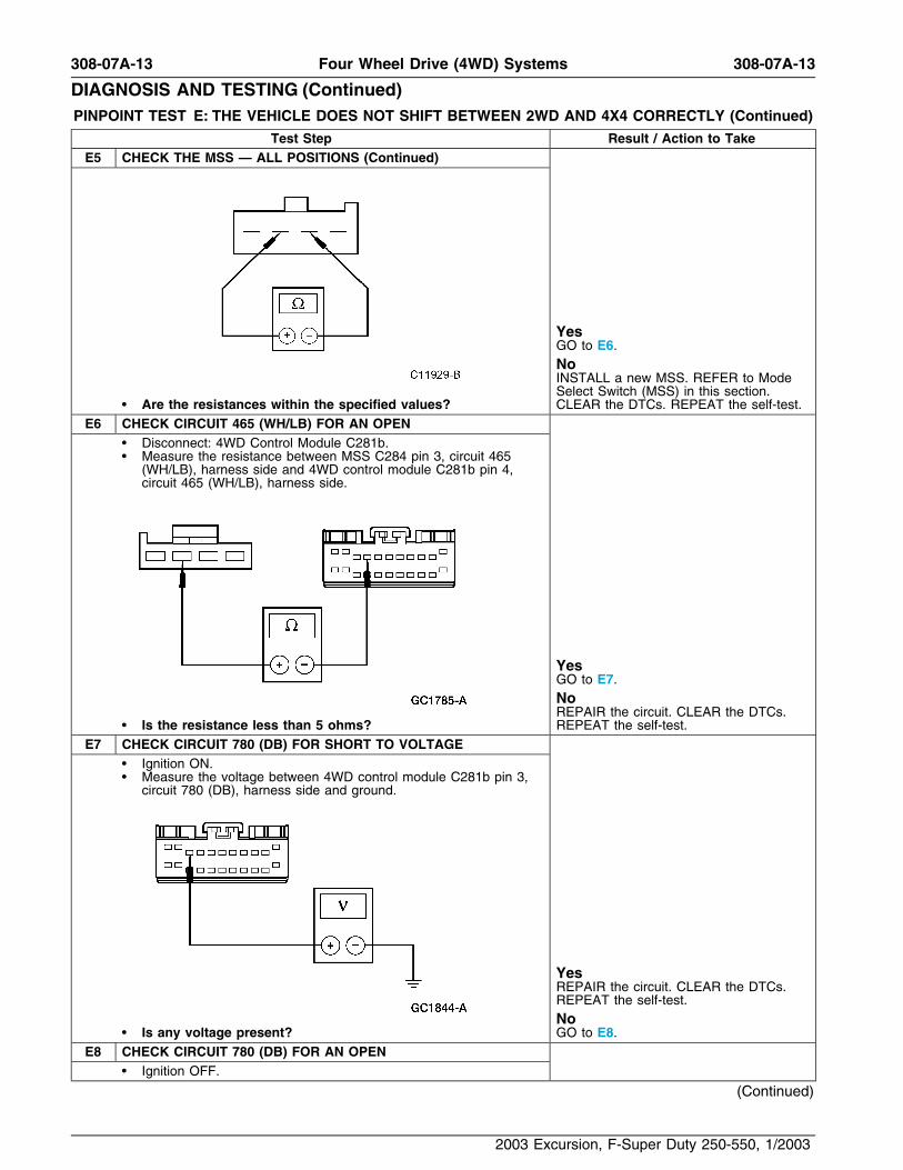
Test Step Result / Action to TakeE5 CHECK THE MSS — ALL POSITIONS (Continued)
YesGO to E6.NoINSTALL a new MSS. REFER to ModeSelect Switch (MSS) in this section.
• Are the resistances within the specified values? CLEAR the DTCs. REPEAT the self-test.E6 CHECK CIRCUIT 465 (WH/LB) FOR AN OPEN
• Disconnect: 4WD Control Module C281b.• Measure the resistance between MSS C284 pin 3, circuit 465
(WH/LB), harness side and 4WD control module C281b pin 4,circuit 465 (WH/LB), harness side.
YesGO to E7.NoREPAIR the circuit. CLEAR the DTCs.
• Is the resistance less than 5 ohms? REPEAT the self-test.E7 CHECK CIRCUIT 780 (DB) FOR SHORT TO VOLTAGE
• Ignition ON.• Measure the voltage between 4WD control module C281b pin 3,
circuit 780 (DB), harness side and ground.
YesREPAIR the circuit. CLEAR the DTCs.REPEAT the self-test.No
• Is any voltage present? GO to E8.E8 CHECK CIRCUIT 780 (DB) FOR AN OPEN
• Ignition OFF.
(Continued)
2003 Excursion, F-Super Duty 250-550, 1/2003

308-07A-14 308-07A-14Four Wheel Drive (4WD) Systems
DIAGNOSIS AND TESTING (Continued)PINPOINT TEST E: THE VEHICLE DOES NOT SHIFT BETWEEN 2WD AND 4X4 CORRECTLY (Continued)
Test Step Result / Action to TakeE8 CHECK CIRCUIT 780 (DB) FOR AN OPEN (Continued)
• Measure the resistance between MSS C284 pin 2, circuit 780(DB), harness side and 4WD control module C281b pin 3, circuit780 (DB), harness side.
YesGO to E9.NoREPAIR the circuit. CLEAR the DTCs.
• Is the resistance less than 5 ohms? REPEAT the self-test.E9 CHECK CIRCUIT 780 (DB) FOR A SHORT TO GROUND
• Measure the resistance between 4WD control module C281b pin3, circuit 780 (DB), harness side and ground.
YesGO to E57.NoREPAIR the circuit. CLEAR the DTCs.
• Is the resistance greater than 10,000 ohms? REPEAT the self-test.E10 CHECK THE VOLTAGE TO THE GEARMOTOR ENCODER
ASSEMBLY• Disconnect: Gearmotor Encoder Assembly C350b.
(Continued)
2003 Excursion, F-Super Duty 250-550, 1/2003

308-07A-15 308-07A-15Four Wheel Drive (4WD) Systems
DIAGNOSIS AND TESTING (Continued)PINPOINT TEST E: THE VEHICLE DOES NOT SHIFT BETWEEN 2WD AND 4X4 CORRECTLY (Continued)
Test Step Result / Action to TakeE10 CHECK THE VOLTAGE TO THE GEARMOTOR ENCODER
ASSEMBLY (Continued)
• NOTE: Voltage is only applied to the transfer case assembly forsix seconds while the 4WD control module active commandCW/CCW is ON.Measure the voltage between gearmotor encoder assemblyC350b, pin 2, circuit 778 (OG), harness side and ground whiletriggering the 4WD control module active command CW/CCW toON; and between gearmotor encoder assembly C350b, pin 1,circuit 777 (YE), harness side and ground while triggering the4WD control module active command CW/CCW to ON.
YesGO to E11.NoIf there is no voltage on circuits 777 (YE)and 778 (OG), GO to E26.If there is no voltage on circuit 777 (YE)only, GO to E12.If there is no voltage on circuit 778 (OG)
• Are the voltages greater than 10 volts? only, GO to E19.E11 CHECK THE VOLTAGE TO THE GEARMOTOR ENCODER
ASSEMBLY• Measure the voltage between gearmotor encoder assembly
C350b, pin 1, circuit 777 (YE), harness side and ground whiletriggering the 4WD control module active command CW/CCW toOFF; and between gearmotor encoder assembly C350b, pin 2,circuit 778 (OG), harness side and ground while triggering the4WD control module active command CW/CCW to OFF.
YesGO to E56.No
• Are the voltages greater than 10 volts? GO to E31.E12 CHECK THE VOLTAGE TO THE GEARMOTOR ENCODER
ASSEMBLY LOW-TO-HIGH SHIFT RELAY — CIRCUIT 704(DG/LG)• Disconnect: Gearmotor Encoder Assembly Low-to-High Relay
C1129.• Ignition ON.
(Continued)
2003 Excursion, F-Super Duty 250-550, 1/2003

308-07A-16 308-07A-16Four Wheel Drive (4WD) Systems
DIAGNOSIS AND TESTING (Continued)PINPOINT TEST E: THE VEHICLE DOES NOT SHIFT BETWEEN 2WD AND 4X4 CORRECTLY (Continued)
Test Step Result / Action to TakeE12 CHECK THE VOLTAGE TO THE GEARMOTOR ENCODER
ASSEMBLY LOW-TO-HIGH SHIFT RELAY — CIRCUIT 704(DG/LG) (Continued)
• Measure the voltage between gearmotor encoder assemblylow-to-high relay C1129 pin 86, circuit 704 (DG/LG), harnessside and ground; and between gearmotor encoder assembly lowto high relay C1129 pin 87, circuit 704 (DG/LG), harness sideand ground.
YesGO to E13.NoREPAIR the circuit. CLEAR the DTCs.
• Are the voltages greater than 10 volts? REPEAT the self-test.E13 CHECK THE GEARMOTOR ENCODER ASSEMBLY
LOW-TO-HIGH RELAY• Ignition OFF. Yes• Carry out the relay component test on the gearmotor encoder GO to E14.
assembly low-to-high relay. Refer to Refer to Wiring Diagrams NoCell 149 for component testing. INSTALL a new gearmotor encoder• Is the relay OK? assembly low-to-high relay. CLEAR theDTCs. REPEAT the self-test.
E14 CHECK CIRCUIT 782 (BN/WH) FOR A SHORT TO VOLTAGE• Disconnect: 4WD Control Module C281b.• Ignition ON.• Measure the voltage between gearmotor encoder assembly
low-to-high C1129 shift relay connector pin 85, circuit 782(BN/WH), harness side and ground.
YesREPAIR the circuit. CLEAR the DTCs.REPEAT the self-test.No
• Is any voltage present? GO to E15.E15 CHECK CIRCUIT 782 (BN/WH) FOR OPEN
• Ignition OFF.
(Continued)
2003 Excursion, F-Super Duty 250-550, 1/2003
308-07A-17 308-07A-17Four Wheel Drive (4WD) Systems
DIAGNOSIS AND TESTING (Continued)PINPOINT TEST E: THE VEHICLE DOES NOT SHIFT BETWEEN 2WD AND 4X4 CORRECTLY (Continued)
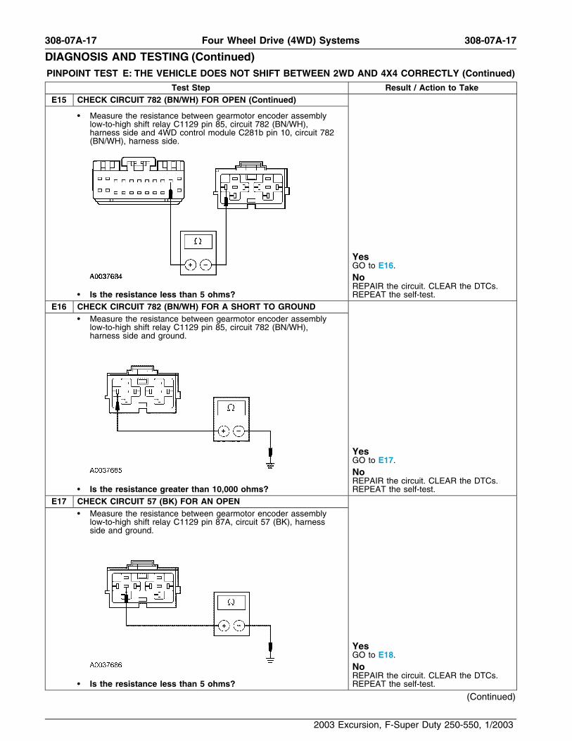
Test Step Result / Action to TakeE15 CHECK CIRCUIT 782 (BN/WH) FOR OPEN (Continued)
• Measure the resistance between gearmotor encoder assemblylow-to-high shift relay C1129 pin 85, circuit 782 (BN/WH),harness side and 4WD control module C281b pin 10, circuit 782(BN/WH), harness side.
YesGO to E16.NoREPAIR the circuit. CLEAR the DTCs.
• Is the resistance less than 5 ohms? REPEAT the self-test.E16 CHECK CIRCUIT 782 (BN/WH) FOR A SHORT TO GROUND
• Measure the resistance between gearmotor encoder assemblylow-to-high shift relay C1129 pin 85, circuit 782 (BN/WH),harness side and ground.
YesGO to E17.NoREPAIR the circuit. CLEAR the DTCs.
• Is the resistance greater than 10,000 ohms? REPEAT the self-test.E17 CHECK CIRCUIT 57 (BK) FOR AN OPEN
• Measure the resistance between gearmotor encoder assemblylow-to-high shift relay C1129 pin 87A, circuit 57 (BK), harnessside and ground.
YesGO to E18.NoREPAIR the circuit. CLEAR the DTCs.
• Is the resistance less than 5 ohms? REPEAT the self-test.
(Continued)
2003 Excursion, F-Super Duty 250-550, 1/2003

308-07A-18 308-07A-18Four Wheel Drive (4WD) Systems
DIAGNOSIS AND TESTING (Continued)PINPOINT TEST E: THE VEHICLE DOES NOT SHIFT BETWEEN 2WD AND 4X4 CORRECTLY (Continued)
Test Step Result / Action to TakeE18 CHECK CIRCUIT 777 (YE) FOR AN OPEN
• Disconnect: Gearmotor Encoder Assembly C350b.• Measure the resistance between gearmotor encoder assembly
low-to-high relay C1129 pin 30, circuit 777 (YE), harness sideand gearmotor encoder assembly C350b, pin 1, circuit 777 (YE),harness side.
YesGO to E57.NoREPAIR the circuit. CLEAR the DTCs.
• Is the resistance less than 5 ohms? REPEAT the self-test.E19 CHECK THE VOLTAGE TO THE GEARMOTOR ENCODER
ASSEMBLY HIGH-TO-LOW RELAY• Remove the gearmotor encoder assembly high-to-low shift relay.• Ignition ON.• Measure the voltage between the gearmotor encoder assembly
high-to-low shift relay C1173 pin 86, circuit 704 (DG/LG),harness side and ground; and between gearmotor encoderassembly high-to-low shift relay C1173 pin 87, circuit 704(DG/LG), harness side and ground.
YesGO to E20.NoREPAIR the circuit. TEST the system for
• Are the voltages greater than 10 volts? normal operation.E20 CHECK THE GEARMOTOR ENCODER ASSEMBLY
HIGH-TO-LOW RELAY• Carry out the relay component test on the gearmotor encoder Yes
assembly high-to-low relay. Refer to Wiring Diagrams Cell 149 GO to E21.for component testing. No• Is the relay OK? INSTALL a new gearmotor encoder
assembly high-to-low relay. CLEAR theDTCs. REPEAT the self-test.
E21 CHECK CIRCUIT 781 (OG/LB) FOR A SHORT TO VOLTAGE• Disconnect: 4WD Control Module C281b.• Ignition ON.
(Continued)
2003 Excursion, F-Super Duty 250-550, 1/2003

308-07A-19 308-07A-19Four Wheel Drive (4WD) Systems
DIAGNOSIS AND TESTING (Continued)PINPOINT TEST E: THE VEHICLE DOES NOT SHIFT BETWEEN 2WD AND 4X4 CORRECTLY (Continued)
Test Step Result / Action to TakeE21 CHECK CIRCUIT 781 (OG/LB) FOR A SHORT TO VOLTAGE
(Continued)
• Measure the voltage between gearmotor encoder assemblyhigh-to-low shift relay C1173 pin 85, circuit 781 (OG/LB),harness side and ground.
YesREPAIR the circuit. CLEAR the DTCs.REPEAT the self-test.No
• Is any voltage present? GO to E22.E22 CHECK CIRCUIT 781 (OG/LB) FOR AN OPEN
• Ignition OFF.• Measure the resistance between gearmotor encoder assembly
high-to-low shift relay C1173 pin 85, circuit 781 (OG/LB),harness side and 4WD control module C281b pin 11, circuit 781(OG/LB), harness side.
YesGO to E23.NoREPAIR the circuit. CLEAR the DTCs.
• Is the resistance less than 5 ohms? REPEAT the self-test.
(Continued)
2003 Excursion, F-Super Duty 250-550, 1/2003
308-07A-20 308-07A-20Four Wheel Drive (4WD) Systems
DIAGNOSIS AND TESTING (Continued)PINPOINT TEST E: THE VEHICLE DOES NOT SHIFT BETWEEN 2WD AND 4X4 CORRECTLY (Continued)
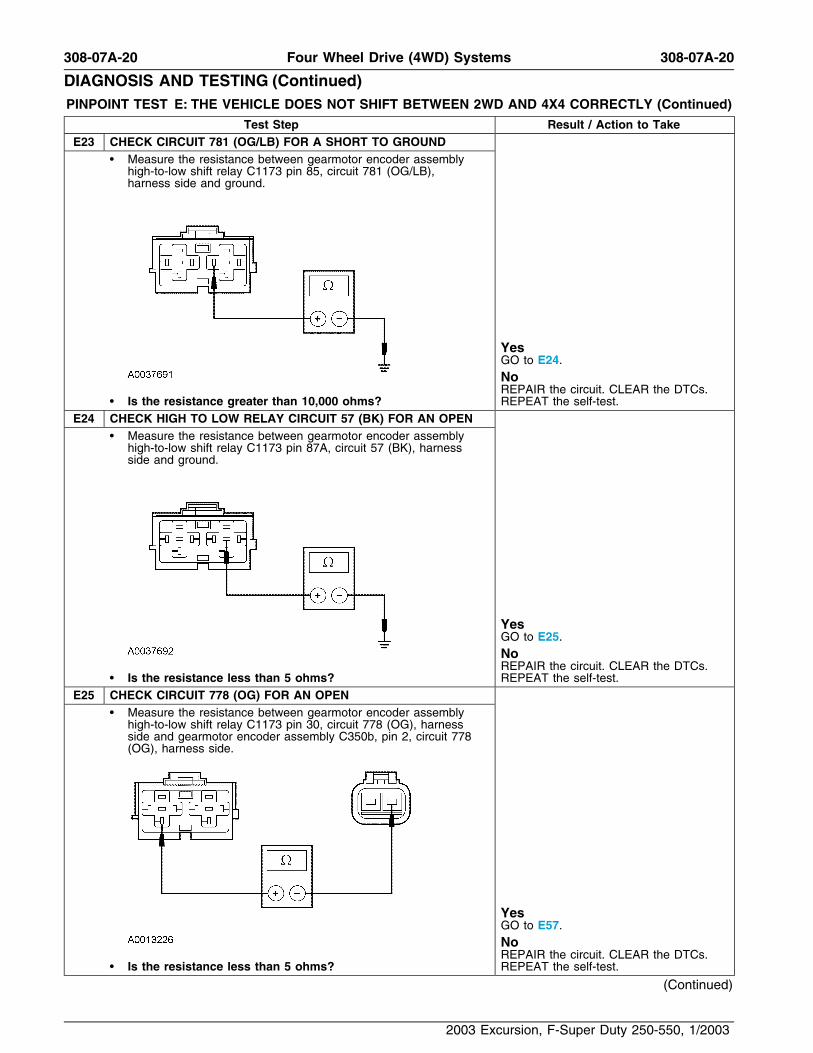
Test Step Result / Action to TakeE23 CHECK CIRCUIT 781 (OG/LB) FOR A SHORT TO GROUND
• Measure the resistance between gearmotor encoder assemblyhigh-to-low shift relay C1173 pin 85, circuit 781 (OG/LB),harness side and ground.
YesGO to E24.NoREPAIR the circuit. CLEAR the DTCs.
• Is the resistance greater than 10,000 ohms? REPEAT the self-test.E24 CHECK HIGH TO LOW RELAY CIRCUIT 57 (BK) FOR AN OPEN
• Measure the resistance between gearmotor encoder assemblyhigh-to-low shift relay C1173 pin 87A, circuit 57 (BK), harnessside and ground.
YesGO to E25.NoREPAIR the circuit. CLEAR the DTCs.
• Is the resistance less than 5 ohms? REPEAT the self-test.E25 CHECK CIRCUIT 778 (OG) FOR AN OPEN
• Measure the resistance between gearmotor encoder assemblyhigh-to-low shift relay C1173 pin 30, circuit 778 (OG), harnessside and gearmotor encoder assembly C350b, pin 2, circuit 778(OG), harness side.
YesGO to E57.NoREPAIR the circuit. CLEAR the DTCs.
• Is the resistance less than 5 ohms? REPEAT the self-test.
(Continued)
2003 Excursion, F-Super Duty 250-550, 1/2003
308-07A-21 308-07A-21Four Wheel Drive (4WD) Systems
DIAGNOSIS AND TESTING (Continued)PINPOINT TEST E: THE VEHICLE DOES NOT SHIFT BETWEEN 2WD AND 4X4 CORRECTLY (Continued)
Test Step Result / Action to TakeE26 CHECK CENTRAL JUNCTION BOX (CJB) FUSE
• Remove the CJB fuse 111 (30A). Yes• Is the CJB fuse OK? GO to E27.
NoGO to E28.
E27 CHECK VOLTAGE AT CJB FUSE• Measure the voltage between CJB fuse 111 (30A) input terminal Yes
and ground. REPAIR circuit 704 (DG/LG). CLEAR the• Is the voltage greater than 10 volts? DTCs. REPEAT the self-test.
NoREPAIR or install a new CJB asnecessary. CLEAR the DTCs. REPEATthe self-test.
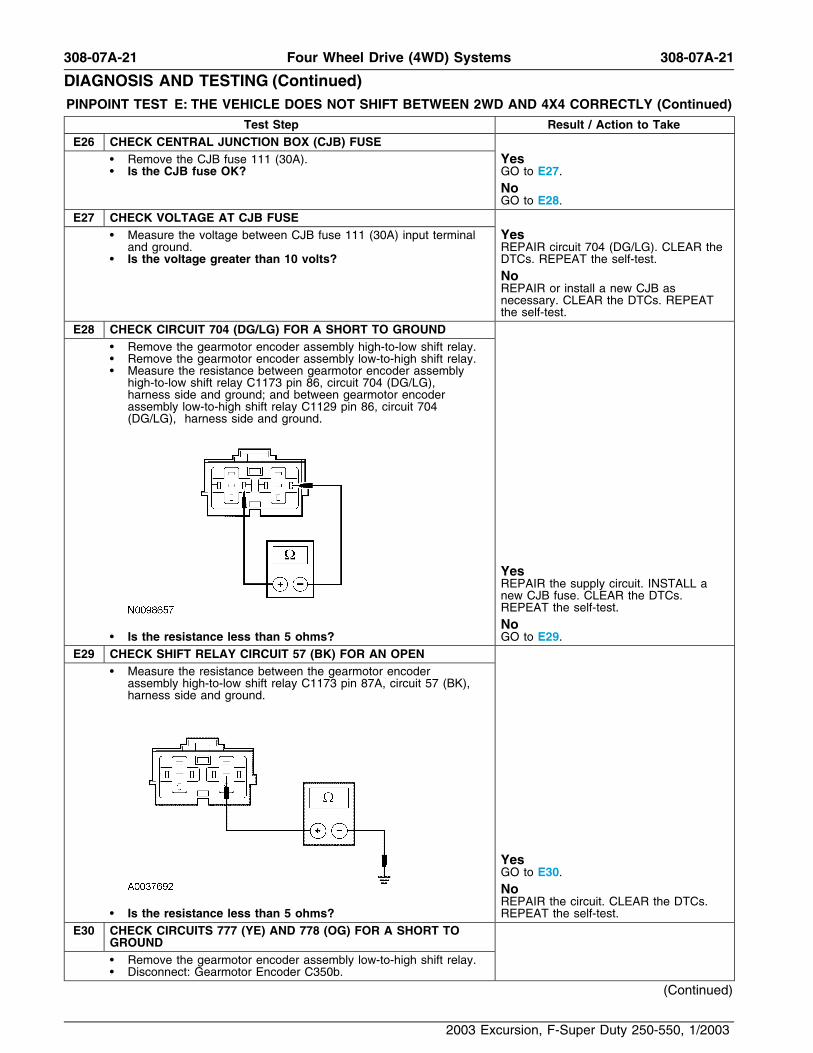
E28 CHECK CIRCUIT 704 (DG/LG) FOR A SHORT TO GROUND• Remove the gearmotor encoder assembly high-to-low shift relay.• Remove the gearmotor encoder assembly low-to-high shift relay.• Measure the resistance between gearmotor encoder assembly
high-to-low shift relay C1173 pin 86, circuit 704 (DG/LG),harness side and ground; and between gearmotor encoderassembly low-to-high shift relay C1129 pin 86, circuit 704(DG/LG), harness side and ground.
YesREPAIR the supply circuit. INSTALL anew CJB fuse. CLEAR the DTCs.REPEAT the self-test.No
• Is the resistance less than 5 ohms? GO to E29.E29 CHECK SHIFT RELAY CIRCUIT 57 (BK) FOR AN OPEN
• Measure the resistance between the gearmotor encoderassembly high-to-low shift relay C1173 pin 87A, circuit 57 (BK),harness side and ground.
YesGO to E30.NoREPAIR the circuit. CLEAR the DTCs.
• Is the resistance less than 5 ohms? REPEAT the self-test.E30 CHECK CIRCUITS 777 (YE) AND 778 (OG) FOR A SHORT TO
GROUND• Remove the gearmotor encoder assembly low-to-high shift relay.• Disconnect: Gearmotor Encoder C350b.
(Continued)
2003 Excursion, F-Super Duty 250-550, 1/2003
308-07A-22 308-07A-22Four Wheel Drive (4WD) Systems
DIAGNOSIS AND TESTING (Continued)PINPOINT TEST E: THE VEHICLE DOES NOT SHIFT BETWEEN 2WD AND 4X4 CORRECTLY (Continued)
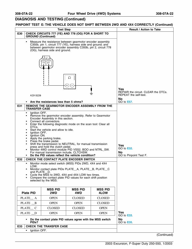
Test Step Result / Action to TakeE30 CHECK CIRCUITS 777 (YE) AND 778 (OG) FOR A SHORT TO
GROUND (Continued)
• Measure the resistance between gearmotor encoder assemblyC350b, pin 1, circuit 777 (YE), harness side and ground; andbetween gearmotor encoder assembly C350b, pin 2, circuit 778(OG), harness side and ground.
YesREPAIR the circuit. CLEAR the DTCs.REPEAT the self-test.No
• Are the resistances less than 5 ohms? GO to E57.E31 REMOVE THE GEARMOTOR ENCODER ASSEMBLY FROM THE
TRANSFER CASE• Ignition OFF.• Remove the gearmotor encoder assembly. Refer to Gearmotor
Encoder Assembly in this section.• Connect all connectors.• Enter the following diagnostic mode on the scan tool: Clear all
DTCs.• Start the vehicle and allow to idle.• Ignition OFF.• Ignition ON.• Apply the parking brake.• Press the brake pedal.• Shift the transmission to NEUTRAL, for manual transmission Yespress and hold the clutch pedal. GO to E32.• Monitor 4WD control module PID VSS2, BOO and NTRL_SW.
For manual transmission include, CLTCHSW. No• Do the PID values reflect the vehicle condition? GO to Pinpoint Test F.
E32 CHECK THE CONTACT PLATE ENCODER SWITCH• Monitor mode select switch (MSS) PIDs 2WD, 4X4 and 4X4
LOW.• Monitor contact plate PIDs PLATE A, PLATE B, PLATE C
and PLATE D.• Cycle the MSS to 2WD, 4X4 and 4X4 LOW two times.• Compare the contact plate PID values for each shift position
selected by the MSS.
MSS PID MSS PID MSS PIDPlate PID 2WD 4WD 4LOW
PLATE A OPEN CLOSED CLOSED
PLATE B OPEN OPEN CLOSED
PLATE C CLOSED CLOSED OPEN
YesPLATE D OPEN OPEN OPENGO to E33.
• Do the contact plate PID values agree with the MSS switch NoPIDs? GO to E35.
E33 CHECK THE TRANSFER CASE• Ignition OFF.
(Continued)
2003 Excursion, F-Super Duty 250-550, 1/2003
308-07A-23 308-07A-23Four Wheel Drive (4WD) Systems
DIAGNOSIS AND TESTING (Continued)PINPOINT TEST E: THE VEHICLE DOES NOT SHIFT BETWEEN 2WD AND 4X4 CORRECTLY (Continued)
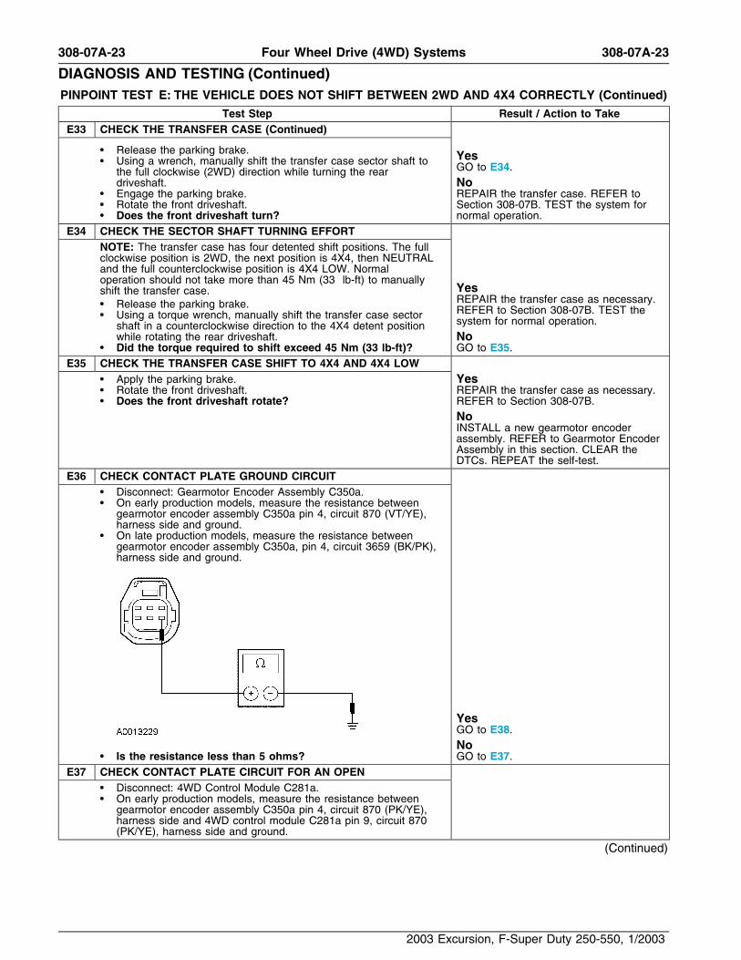
Test Step Result / Action to TakeE33 CHECK THE TRANSFER CASE (Continued)
• Release the parking brake. Yes• Using a wrench, manually shift the transfer case sector shaft to GO to E34.the full clockwise (2WD) direction while turning the reardriveshaft. No
• Engage the parking brake. REPAIR the transfer case. REFER to• Rotate the front driveshaft. Section 308-07B. TEST the system for• Does the front driveshaft turn? normal operation.
E34 CHECK THE SECTOR SHAFT TURNING EFFORTNOTE: The transfer case has four detented shift positions. The fullclockwise position is 2WD, the next position is 4X4, then NEUTRALand the full counterclockwise position is 4X4 LOW. Normaloperation should not take more than 45 Nm (33 lb-ft) to manually
Yesshift the transfer case.REPAIR the transfer case as necessary.• Release the parking brake. REFER to Section 308-07B. TEST the• Using a torque wrench, manually shift the transfer case sector system for normal operation.shaft in a counterclockwise direction to the 4X4 detent position
while rotating the rear driveshaft. No• Did the torque required to shift exceed 45 Nm (33 lb-ft)? GO to E35.
E35 CHECK THE TRANSFER CASE SHIFT TO 4X4 AND 4X4 LOW• Apply the parking brake. Yes• Rotate the front driveshaft. REPAIR the transfer case as necessary.• Does the front driveshaft rotate? REFER to Section 308-07B.
NoINSTALL a new gearmotor encoderassembly. REFER to Gearmotor EncoderAssembly in this section. CLEAR theDTCs. REPEAT the self-test.
E36 CHECK CONTACT PLATE GROUND CIRCUIT• Disconnect: Gearmotor Encoder Assembly C350a.• On early production models, measure the resistance between
gearmotor encoder assembly C350a pin 4, circuit 870 (VT/YE),harness side and ground.
• On late production models, measure the resistance betweengearmotor encoder assembly C350a, pin 4, circuit 3659 (BK/PK),harness side and ground.
YesGO to E38.No
• Is the resistance less than 5 ohms? GO to E37.E37 CHECK CONTACT PLATE CIRCUIT FOR AN OPEN
• Disconnect: 4WD Control Module C281a.• On early production models, measure the resistance between
gearmotor encoder assembly C350a pin 4, circuit 870 (PK/YE),harness side and 4WD control module C281a pin 9, circuit 870(PK/YE), harness side and ground.
(Continued)
2003 Excursion, F-Super Duty 250-550, 1/2003

308-07A-24 308-07A-24Four Wheel Drive (4WD) Systems
DIAGNOSIS AND TESTING (Continued)PINPOINT TEST E: THE VEHICLE DOES NOT SHIFT BETWEEN 2WD AND 4X4 CORRECTLY (Continued)
Test Step Result / Action to TakeE37 CHECK CONTACT PLATE CIRCUIT FOR AN OPEN (Continued)
• On late production models, measure the resistance betweengearmotor encoder assembly C350a, pin 4, circuit 3659 (BK/PK),harness side and 4WD control module C281a pin 9, circuit 3659(BK/PK), harness side and ground.
YesGO to E58.NoREPAIR the circuit. CLEAR the DTCs.
• Is the resistance less than 5 ohms? REPEAT the self-test.E38 CHECK CIRCUIT 976 (OG) FOR CONTACT PLATE VOLTAGE
SUPPLY• Ignition ON.• Measure the voltage between gearmotor encoder assembly
C350a pin 2, circuit 976 (OG), harness side and ground. ForExcursion, the voltage should cycle between 0 volts and 1 to 3volts. All others should be greater than 9 volts.
YesGO to E41.
• Is the voltage reading as specified for the vehicle being Notested? GO to E39.
E39 CHECK CIRCUIT 976 (OG) FOR A SHORT TO GROUND• Disconnect: 4WD Control Module C281a.
(Continued)
2003 Excursion, F-Super Duty 250-550, 1/2003

308-07A-25 308-07A-25Four Wheel Drive (4WD) Systems
DIAGNOSIS AND TESTING (Continued)PINPOINT TEST E: THE VEHICLE DOES NOT SHIFT BETWEEN 2WD AND 4X4 CORRECTLY (Continued)
Test Step Result / Action to TakeE39 CHECK CIRCUIT 976 (OG) FOR A SHORT TO GROUND
(Continued)
• Measure the resistance between gearmotor encoder assemblyC350a pin 2, circuit 976 (OG), harness side and ground.
YesGO to E40.NoREPAIR the circuit. CLEAR the DTCs.
• Is the resistance greater than 10,000 ohms? REPEAT the self-test.E40 CHECK CIRCUIT 976 (OG) FOR AN OPEN
• Measure the resistance between gearmotor encoder assemblyC350a pin 2, circuit 976 (OG), harness side and 4WD controlmodule C281b pin 5, circuit 976 (OG), harness side.
YesGO to E58.NoREPAIR the circuit. CLEAR the DTCs.
• Is the resistance less than 5 ohms? REPEAT the self-test.E41 CHECK CONTACT PLATE SWITCH A— CIRCUIT 771 (VT/YE)
• Connect: 4WD Control Module C281b.• Monitor the 4WD control module PID: PLATE A.• Connect a jumper wire between gearmotor encoder assembly
C350a pin 5, circuit 771 (VT/YE), harness side and ground.
YesGO to E45.
• Does the PID: PLATE A toggle between CLOSED and NoOPEN when ground is removed and applied? GO to E42.
(Continued)
2003 Excursion, F-Super Duty 250-550, 1/2003

308-07A-26 308-07A-26Four Wheel Drive (4WD) Systems
DIAGNOSIS AND TESTING (Continued)PINPOINT TEST E: THE VEHICLE DOES NOT SHIFT BETWEEN 2WD AND 4X4 CORRECTLY (Continued)
Test Step Result / Action to TakeE42 CHECK CIRCUIT 771 (VT/YE) FOR A SHORT TO VOLTAGE
• Measure the voltage between gearmotor encoder assemblyC350a pin 5, circuit 771 (VT/YE), harness side and ground.
YesREPAIR the circuit. CLEAR the DTCs.REPEAT the self-test.No
• Is voltage present? GO to E43.E43 CHECK CIRCUIT 771 (VT/YE) FOR A SHORT TO GROUND
• Measure the resistance between gearmotor encoder assemblyC350a pin 5, circuit 771 (VT/YE), harness side and ground.
YesGO to E44.NoREPAIR the circuit. CLEAR the DTCs.
• Is the resistance greater than 10,000 ohms? REPEAT the self-test.E44 CHECK CIRCUIT 771 (VT/YE) FOR AN OPEN
• Measure the resistance between gearmotor encoder assemblyC350a pin 5, circuit 771 (VT/YE), harness side and 4WD controlmodule C281b pin 15, circuit 771 (VT/YE), harness side.
YesGO to E58.NoREPAIR the circuit. CLEAR the DTCs.
• Is the resistance less than 5 ohms? REPEAT the self-test.E45 CHECK THE CONTACT PLATE SWITCH B — CIRCUIT 764
(BN/WH)• Monitor the 4WD control module PID: PLATE B.
(Continued)
2003 Excursion, F-Super Duty 250-550, 1/2003

308-07A-27 308-07A-27Four Wheel Drive (4WD) Systems
DIAGNOSIS AND TESTING (Continued)PINPOINT TEST E: THE VEHICLE DOES NOT SHIFT BETWEEN 2WD AND 4X4 CORRECTLY (Continued)
Test Step Result / Action to TakeE45 CHECK THE CONTACT PLATE SWITCH B — CIRCUIT 764
(BN/WH) (Continued)
• Connect a jumper wire between gearmotor encoder assembly,C350a pin 3, circuit 764 (BN/WH), harness side and ground.
YesGO to E49.
• Does the PID: PLATE B toggle between CLOSED and NoOPEN when ground is removed and applied? GO to E46.
E46 CHECK CIRCUIT 764 (BN/WH) FOR SHORT TO VOLTAGE• Measure the voltage between gearmotor encoder assembly
C350a pin 3, circuit 764 (BN/WH), harness side and ground.
YesREPAIR the circuit. CLEAR the DTCs.REPEAT the self-test.No
• Is voltage present? GO to E47.E47 CHECK CIRCUIT 764 (BN/WH) FOR A SHORT TO GROUND
• Measure the resistance between gearmotor encoder assemblyC350a pin 3, circuit 764 (BN/WH), harness side and ground.
YesGO to E48.NoREPAIR the circuit. CLEAR the DTCs.
• Is the resistance greater than 10,000 ohms? REPEAT the self-test.E48 CHECK CIRCUIT 764 (BN/WH) FOR OPEN
• Disconnect: 4WD Control Module C281b.
(Continued)
2003 Excursion, F-Super Duty 250-550, 1/2003
308-07A-28 308-07A-28Four Wheel Drive (4WD) Systems
DIAGNOSIS AND TESTING (Continued)PINPOINT TEST E: THE VEHICLE DOES NOT SHIFT BETWEEN 2WD AND 4X4 CORRECTLY (Continued)
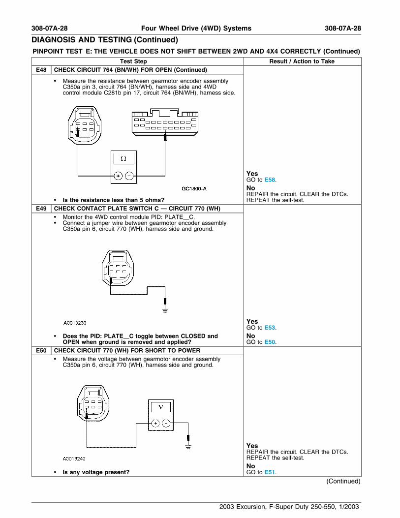
Test Step Result / Action to TakeE48 CHECK CIRCUIT 764 (BN/WH) FOR OPEN (Continued)
• Measure the resistance between gearmotor encoder assemblyC350a pin 3, circuit 764 (BN/WH), harness side and 4WDcontrol module C281b pin 17, circuit 764 (BN/WH), harness side.
YesGO to E58.NoREPAIR the circuit. CLEAR the DTCs.
• Is the resistance less than 5 ohms? REPEAT the self-test.E49 CHECK CONTACT PLATE SWITCH C — CIRCUIT 770 (WH)
• Monitor the 4WD control module PID: PLATE C.• Connect a jumper wire between gearmotor encoder assembly
C350a pin 6, circuit 770 (WH), harness side and ground.
YesGO to E53.
• Does the PID: PLATE C toggle between CLOSED and NoOPEN when ground is removed and applied? GO to E50.
E50 CHECK CIRCUIT 770 (WH) FOR SHORT TO POWER• Measure the voltage between gearmotor encoder assembly
C350a pin 6, circuit 770 (WH), harness side and ground.
YesREPAIR the circuit. CLEAR the DTCs.REPEAT the self-test.No
• Is any voltage present? GO to E51.
(Continued)
2003 Excursion, F-Super Duty 250-550, 1/2003

308-07A-29 308-07A-29Four Wheel Drive (4WD) Systems
DIAGNOSIS AND TESTING (Continued)PINPOINT TEST E: THE VEHICLE DOES NOT SHIFT BETWEEN 2WD AND 4X4 CORRECTLY (Continued)
Test Step Result / Action to TakeE51 CHECK CIRCUIT 770 (WH) FOR A SHORT TO GROUND
• Measure the resistance between gearmotor encoder assemblyC350a pin 6, circuit 770 (WH), harness side and ground.
YesGO to E52.NoREPAIR the circuit. CLEAR the DTCs.
• Is the resistance greater than 10,000 ohms? REPEAT the self-test.E52 CHECK CIRCUIT 770 (WH) FOR AN OPEN
• Disconnect: 4WD Control Module C281b.• Measure the resistance between gearmotor encoder assembly
C350a pin 6, circuit 770 (WH), harness side and 4WD controlmodule C281b pin 18, circuit 770 (WH), harness side.
YesGO to E58.NoREPAIR the circuit. CLEAR the DTCs.
• Is the resistance less than 5 ohms? REPEAT the self-test.E53 CHECK CONTACT PLATE SWITCH D — CIRCUIT 763 (OG/WH)
• Monitor the 4WD control module PID: PLATE D.• Connect jumper wire between gearmotor encoder assembly
C350a pin 1, circuit 763 (OG/WH), harness side and ground.
YesINSTALL a new gearmotor encoderassembly. REFER to Gearmotor EncoderAssembly in this section. CLEAR theDTCs. REPEAT the self-test.
• Does the PID: PLATE D toggle between CLOSED and NoOPEN when ground is removed and applied? GO to E54.
(Continued)
2003 Excursion, F-Super Duty 250-550, 1/2003

308-07A-30 308-07A-30Four Wheel Drive (4WD) Systems
DIAGNOSIS AND TESTING (Continued)PINPOINT TEST E: THE VEHICLE DOES NOT SHIFT BETWEEN 2WD AND 4X4 CORRECTLY (Continued)
Test Step Result / Action to TakeE54 CHECK CIRCUIT 763 (OG/WH) FOR A SHORT TO VOLTAGE
• Measure the voltage between gearmotor encoder assemblyC350a pin 1, circuit 763 (OG/WH), harness side and ground.
YesREPAIR the circuit. CLEAR the DTCs.REPEAT the self-test.No
• Is any voltage present? GO to E55.E55 CHECK CIRCUIT 763 (OG/WH) FOR A SHORT TO GROUND
• Measure the resistance between gearmotor encoder assemblyC350a pin 1, circuit 763 (OG/WH), harness side and ground.
YesGO to E56.NoREPAIR the circuit. CLEAR the DTCs.
• Is the resistance greater than 10,000 ohms? REPEAT the self-test.E56 CHECK CIRCUIT 763 (OG/WH) FOR OPEN
• Disconnect: 4WD Control Module C281b.• Measure the resistance between gearmotor encoder assembly
C350a pin 1, circuit 763 (OG/WH), harness side and 4WDcontrol module C281b pin 16, circuit 763 (OG/WH), harnessside.
YesGO to E58.NoREPAIR the circuit. CLEAR the DTCs.
• Is the resistance less than 5 ohms? REPEAT the self-test.
(Continued)
2003 Excursion, F-Super Duty 250-550, 1/2003

308-07A-31 308-07A-31Four Wheel Drive (4WD) Systems
DIAGNOSIS AND TESTING (Continued)PINPOINT TEST E: THE VEHICLE DOES NOT SHIFT BETWEEN 2WD AND 4X4 CORRECTLY (Continued)
Test Step Result / Action to TakeE57 CHECK CIRCUIT 777 (YE) AND 778 (OG) FOR A SHORT TO
VOLTAGE• Remove the gearmotor encoder high-to-low shift relay.• Remove the gearmotor encoder low-to-high shift relay.• Measure the voltage between gearmotor encoder assembly
C350b, pin 1, circuit 777 (YE), harness side and ground; andbetween gearmotor encoder assembly C350b, pin 2, circuit 778(OG), harness side and ground.
YesREPAIR the circuit. CLEAR the DTCs.REPEAT the self-test.NoCARRY OUT the ISO Relay ComponentTest on both shift relays. Refer to WiringDiagrams Cell 149 for component testing.
• Is any voltage present? CLEAR the DTCs. REPEAT the self-test.E58 CHECK FOR CORRECT MODULE OPERATION
• Check for: YesINSTALL a new 4WD control module.• corrosion REFER to Four Wheel Drive (4WD)• pushed-out pins Control Module in this section. CLEAR the• Connect any disconnected connectors making sure they are DTCs. REPEAT the self-test.seated correctly.
• Make sure all other system connectors are fully seated. No• Operate the system and verify the concern is still present. The system is operating correctly at this• Is the concern still present? time. Concern may have been caused by
a loose or corroded connector. CLEAR theDTCs. REPEAT the self-test.
PINPOINT TEST F: THE VEHICLE DOES NOT SHIFT BETWEEN 4X4 AND 4X4 LOW MODES CORRECTLY
Test Step Result / Action to TakeF1 CHECK THE IGNITION STATES — MONITOR THE 4WD
CONTROL MODULE IGNITION PIDs• NOTE: If the vehicle is equipped with a manual transmission,
depress the clutch pedal while turning the ignition switch to theSTART position.Monitor the 4WD control module ignition switch PIDs whileturning the ignition switch through all positions.
Ignition SwitchPosition PID Expected Value
OFF IGN O/L OFF
ACCESSORY IGN ACC ACCY
RUN IGN R RUN YesGO to F2.START IGN S STARTNo
• Do the PID values agree with the ignition switch positions? REFER to Section 211-05.
(Continued)
2003 Excursion, F-Super Duty 250-550, 1/2003
308-07A-32 308-07A-32Four Wheel Drive (4WD) Systems
DIAGNOSIS AND TESTING (Continued)PINPOINT TEST F: THE VEHICLE DOES NOT SHIFT BETWEEN 4X4 AND 4X4 LOW MODES CORRECTLY
(Continued)
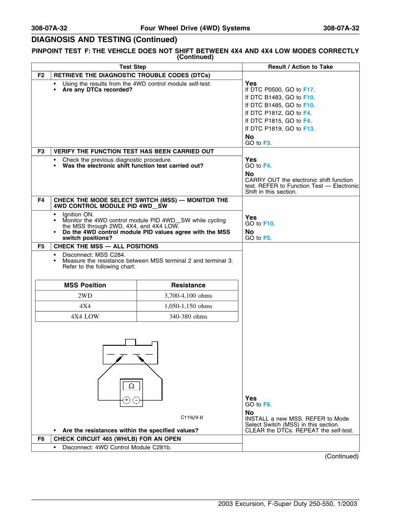
Test Step Result / Action to TakeF2 RETRIEVE THE DIAGNOSTIC TROUBLE CODES (DTCs)
• Using the results from the 4WD control module self-test: Yes• Are any DTCs recorded? If DTC P0500, GO to F17.
If DTC B1483, GO to F10.If DTC B1485, GO to F10.If DTC P1812, GO to F4.If DTC P1815, GO to F4.If DTC P1819, GO to F13.NoGO to F3.
F3 VERIFY THE FUNCTION TEST HAS BEEN CARRIED OUT• Check the previous diagnostic procedure. Yes• Was the electronic shift function test carried out? GO to F4.
NoCARRY OUT the electronic shift functiontest. REFER to Function Test — ElectronicShift in this section.
F4 CHECK THE MODE SELECT SWITCH (MSS) — MONITOR THE4WD CONTROL MODULE PID 4WD SW• Ignition ON. Yes• Monitor the 4WD control module PID 4WD SW while cycling GO to F10.the MSS through 2WD, 4X4, and 4X4 LOW.• Do the 4WD control module PID values agree with the MSS No
switch positions? GO to F5.F5 CHECK THE MSS — ALL POSITIONS
• Disconnect: MSS C284.• Measure the resistance between MSS terminal 2 and terminal 3.
Refer to the following chart:
MSS Position Resistance
2WD 3,700-4,100 ohms
4X4 1,050-1,150 ohms
4X4 LOW 340-380 ohms
YesGO to F6.NoINSTALL a new MSS. REFER to ModeSelect Switch (MSS) in this section.
• Are the resistances within the specified values? CLEAR the DTCs. REPEAT the self-test.F6 CHECK CIRCUIT 465 (WH/LB) FOR AN OPEN
• Disconnect: 4WD Control Module C281b.
(Continued)
2003 Excursion, F-Super Duty 250-550, 1/2003

308-07A-33 308-07A-33Four Wheel Drive (4WD) Systems
DIAGNOSIS AND TESTING (Continued)PINPOINT TEST F: THE VEHICLE DOES NOT SHIFT BETWEEN 4X4 AND 4X4 LOW MODES CORRECTLY
(Continued)
Test Step Result / Action to TakeF6 CHECK CIRCUIT 465 (WH/LB) FOR AN OPEN (Continued)
• Measure the resistance between MSS C284 pin 3, circuit 465(WH/LB), harness side and 4WD control module C281b pin 4,circuit 465 (WH/LB), harness side.
YesGO to F7.NoREPAIR the circuit. CLEAR the DTCs.
• Is the resistance less than 5 ohms? REPEAT the self-test.F7 CHECK CIRCUIT 780 (DB) FOR SHORT TO VOLTAGE
• Ignition ON.• Measure the voltage between 4WD control module C281b pin 3,
circuit 780 (DB), harness side and ground.
YesREPAIR the circuit. CLEAR the DTCs.REPEAT the self-test.No
• Is any voltage present? GO to F8.F8 CHECK CIRCUIT 780 (DB) FOR AN OPEN
• Ignition OFF.• Measure the resistance between MSS C284 pin 2, circuit 780
(DB), harness side and 4WD control module C281b pin 3, circuit780 (DB), harness side.
YesGO to F9.NoREPAIR the circuit. CLEAR the DTCs.
• Is the resistance less than 5 ohms? REPEAT the self-test.
(Continued)
2003 Excursion, F-Super Duty 250-550, 1/2003

308-07A-34 308-07A-34Four Wheel Drive (4WD) Systems
DIAGNOSIS AND TESTING (Continued)PINPOINT TEST F: THE VEHICLE DOES NOT SHIFT BETWEEN 4X4 AND 4X4 LOW MODES CORRECTLY
(Continued)
Test Step Result / Action to TakeF9 CHECK CIRCUIT 780 (DB) FOR A SHORT TO GROUND
• Measure the resistance between 4WD control module C281b pin3, circuit 780 (DB), harness side and ground.
YesGO to F20.NoREPAIR the circuit. CLEAR the DTCs.
• Is the resistance greater than 10,000 ohms? REPEAT the self-test.F10 CHECK BRAKE PEDAL POSITION (BPP) SWITCH 4WD
CONTROL MODULE PID• Press and hold the brake pedal. Yes• Monitor the 4WD control module PID: BOO 4x4. GO to F13.• Does the 4WD control module PID: BOO read ON when the
brake pedal is depressed and OFF when the brake pedal is Noreleased? GO to F11.
F11 CHECK THE BRAKE LAMPS• Press and hold the brake pedal. Yes• Did the brake lamps illuminate? GO to F12.
NoREFER to Section 417-01. CLEAR theDTCs. REPEAT the self-test.
F12 CHECK CIRCUIT 810 (RD/LG) FOR AN OPEN• Disconnect: 4WD Control Module C281b.• Disconnect: BPP C278.• Measure the resistance between BPP switch C278 pin 2, circuit
810 (RD/LG), harness side and 4WD control module C281b pin12, circuit 810 (RD/LG), harness side.
YesGO to F13.NoREPAIR the circuit. CLEAR the DTCs.
• Is the resistance less than 5 ohms? REPEAT the self-test.F13 CHECK THE DIGITAL TR SENSOR PID NTRL SW
• For manual transmission, monitor 4WD control module PID:CLTCHSW. For automatic transmissions monitor 4WD controlmodule PID: NTRL SW.
• For automatic transmissions, place the transmission rangeselector lever in NEUTRAL. For manual transmissions, pressand hold the clutch pedal.
(Continued)
2003 Excursion, F-Super Duty 250-550, 1/2003

308-07A-35 308-07A-35Four Wheel Drive (4WD) Systems
DIAGNOSIS AND TESTING (Continued)PINPOINT TEST F: THE VEHICLE DOES NOT SHIFT BETWEEN 4X4 AND 4X4 LOW MODES CORRECTLY
(Continued)
Test Step Result / Action to TakeF13 CHECK THE DIGITAL TR SENSOR PID NTRL SW (Continued)
• For automatic transmissions, verify 4WD control module PIDreads NTRL. For manual transmissions, verify 4WD controlmodule PID: CLTCHSW reads ENGAGED.
• For automatic transmissions, shift the selector lever through allpositions while monitoring 4WD control module PID NTRL SW. Yes• For manual transmission: does the 4WD control module GO to F17.PID: CLTCHSW read ENGAGED? For automatictransmission: does the 4WD control module PID: NTRL SW Noread NTRL only for the NEUTRAL position? GO to F14.
F14 CHECK THE DIGITAL TR SENSOR• Disconnect: Digital TR Sensor C167.• Monitor 4WD control module PID: NTRL SW. Yes• Verify the 4WD control module PID: NTRL SW reads not REFER to Section 307-01A to diagnoseNTRL. the digital TR sensor. CLEAR the DTCs.• Connect a jumper wire between digital TR sensor C167 pin 8, REPEAT the self-test.circuit 463 (RD/WH), harness side and ground.• Does the 4WD control module PID: NTRL SW indicate No
NTRL? GO to F15.F15 CHECK CIRCUIT 463 (RD/WH) FOR AN OPEN
• Disconnect: 4WD Control Module C281b.• Measure the resistance between digital TR sensor C167 pin 8,
circuit 463 (RD/WH), harness side and 4WD control moduleC281b pin 1, circuit 463 (RD/WH), harness side.
YesGO to F16.NoREPAIR the DTCs. CLEAR the DTCs.
• Is the resistance less than 5 ohms? REPEAT the self-test.F16 CHECK CIRCUIT 463 (RD/WH) FOR A SHORT TO GROUND
• Measure the resistance between digital TR sensor C167 pin 8,circuit 463 (RD/WH), harness side and ground.
YesGO to F20.NoREPAIR the circuit. CLEAR the DTCs.
• Is the resistance greater than 10,000 ohms? REPEAT the self-test.
(Continued)
2003 Excursion, F-Super Duty 250-550, 1/2003

308-07A-36 308-07A-36Four Wheel Drive (4WD) Systems
DIAGNOSIS AND TESTING (Continued)PINPOINT TEST F: THE VEHICLE DOES NOT SHIFT BETWEEN 4X4 AND 4X4 LOW MODES CORRECTLY
(Continued)
Test Step Result / Action to TakeF17 CHECK THE VEHICLE SPEED SIGNAL
• Monitor anti-lock brake module (ABS) PID: R WSSP. Yes• Monitor 4WD control module PID: VSS2 while driving the vehicle GO to Pinpoint Test E.0 to 88.5 km/h (55 mph) at a steady rate.• Does the 4WD control module PID: VSS2 agree with ABS No
PID: R WSSP? GO to F18.F18 CHECK THE SPEEDOMETER
• Monitor the speedometer. Yes• Monitor 4WD control module PID: VSS2 while driving the vehicle REFER to Section 413-01 to diagnose the
0 to 88.5 km/h (55 mph) at a steady rate. speedometer. CLEAR the DTCs. TEST the• Does the 4WD control module PID: VSS2 agree with system for normal operation.
speedometer? NoGO to F19.
F19 CHECK CIRCUIT 679 (GY/BK) FOR AN OPEN• Disconnect: 4WD Control Module C281c.• Disconnect: ABS C135.• Measure the resistance between 4WD control module C281c,
pin 9, circuit 679 (GY/BK), harness side and ABS C135 pin 11,circuit 679 (GY/BK), harness side.
YesGO to F20.NoREPAIR the circuit. CLEAR the DTCs.
• Is the resistance less than 5 ohms? REPEAT the self-test.F20 CHECK FOR CORRECT MODULE OPERATION
• Check for: YesINSTALL a new 4WD control module.• corrosion REFER to Four Wheel Drive (4WD)• pushed-out pins Control Module in this section. CLEAR the• Connect any disconnected connectors making sure they seat DTCs. REPEAT the self-test.correctly.
• Make sure all other system connectors are fully seated. No• Operate the system and verify the concern is still present. The system is operating correctly at this• Is the concern still present? time. Concern may have been caused by
a loose or corroded connector. CLEAR theDTCs. REPEAT the self-test.
PINPOINT TEST G: THE FRONT AXLE DOES NOT ENGAGE CORRECTLY
Test Step Result / Action to TakeG1 RETRIEVE THE DIAGNOSTIC TROUBLE CODES (DTCs)
• Refer to the recorded results of the 4WD control module Yesself-test. If DTC P1832, GO to G2.
• Were any DTCs retrieved? If DTC P1834, GO to G5.If DTC P1876, GO to G5.If DTC P1877, GO to G7.NoGO to G7.
(Continued)
2003 Excursion, F-Super Duty 250-550, 1/2003

308-07A-37 308-07A-37Four Wheel Drive (4WD) Systems
DIAGNOSIS AND TESTING (Continued)PINPOINT TEST G: THE FRONT AXLE DOES NOT ENGAGE CORRECTLY (Continued)
Test Step Result / Action to TakeG2 CHECK FOR VOLTAGE TO THE PULSE VACUUM HUBLOCK
(PVH) SOLENOID• Disconnect: PVH Solenoid C1247.• Ignition ON.• Measure the voltage between PVH solenoid C1247, pin 2, circuit
295 (LB/PK), harness side and ground.
YesGO to G3.NoREPAIR circuit 295 (LB/BK). CLEAR the
• Is the voltage greater than 10 volts? DTCs. REPEAT the self-test.G3 CHECK CIRCUITS 605 (RD) AND 145 (GY/BK) FOR A SHORT
TO VOLTAGE• Measure the voltage between PVH solenoid C1247, pin 3, circuit
605 (RD), harness side and ground; and between PVH solenoidC1247, pin 1, circuit 145 (GY/BK), harness side and ground.
YesREPAIR the circuit. CLEAR the DTCs.REPEAT the self-test.No
• Is any voltage present? GO to G4.
(Continued)
2003 Excursion, F-Super Duty 250-550, 1/2003

308-07A-38 308-07A-38Four Wheel Drive (4WD) Systems
DIAGNOSIS AND TESTING (Continued)PINPOINT TEST G: THE FRONT AXLE DOES NOT ENGAGE CORRECTLY (Continued)
Test Step Result / Action to TakeG4 CHECK CIRCUITS 605 (RD) AND 145 (GY/BK) FOR A SHORT
TO GROUND• Measure the resistance between PVH solenoid C1247, pin 3,
circuit 605 (RD), harness side and ground; and between PVHsolenoid C1247, pin 1, circuit 145 (GY/BK), harness side andground.
YesGO to G5.NoREPAIR the circuit. CLEAR the DTCs.
• Are the resistances greater than 10,000 ohms? REPEAT the self-test.G5 CHECK CIRCUITS 605 (RD) AND 145 (GY/BK) FOR AN OPEN
• Disconnect: 4WD Control Module C281b.• Measure the resistance between 4WD control module C281b pin
6, circuit 605 (RD), harness side and PVH solenoid C1247, pin3, circuit 605 (RD), harness side.
• Measure the resistance between 4WD control module C281b pin7, circuit 145 (GY/BK), harness side and PVH solenoid C1247,pin 1, circuit 145 (GY/BK), harness side.
YesGO to G6.NoREPAIR the circuit. CLEAR the DTCs.
• Are the resistances less than 5 ohms? REPEAT the self-test.
(Continued)
2003 Excursion, F-Super Duty 250-550, 1/2003

308-07A-39 308-07A-39Four Wheel Drive (4WD) Systems
DIAGNOSIS AND TESTING (Continued)PINPOINT TEST G: THE FRONT AXLE DOES NOT ENGAGE CORRECTLY (Continued)
Test Step Result / Action to TakeG6 CHECK THE PVH SOLENOID COILS
• Measure the resistance between the PVH solenoid terminal 1and terminal 3; and measure the resistance between PVHsolenoid terminal 2 and terminal 3.
YesGO to G27.NoINSTALL a new PVH solenoid. REFER toPulse Vacuum Hublock (PVH) Solenoid inthis section. CLEAR the DTCs. REPEAT
• Are the resistances between 45 and 55 ohms? the self-test.G7 CHECK ENGAGE VACUUM SUPPLY TO THE RIGHT KNUCKLE
NOTE: The remaining steps require the use of a calibrated vacuumgauge that is accurate to within a minimum of 0.1 in-Hg.• Make sure hublocks are in the AUTO position.• Lift and support the vehicle off the ground until the front tires
can be spun freely. Refer to Section 100-02.• NOTE: The engine is required to be at idle during the following
steps to supply the vacuum required for the hublocks to engageand disengage.Start the engine and allow to idle.
• Turn the MSS to the 2WD position and wait 15 seconds. Ifswitching from 4X4 mode, wait an additional 45 seconds.
• Disconnect the vacuum line at the right front knuckle and installa vacuum gauge on the line.
(Continued)
2003 Excursion, F-Super Duty 250-550, 1/2003
308-07A-40 308-07A-40Four Wheel Drive (4WD) Systems
DIAGNOSIS AND TESTING (Continued)PINPOINT TEST G: THE FRONT AXLE DOES NOT ENGAGE CORRECTLY (Continued)
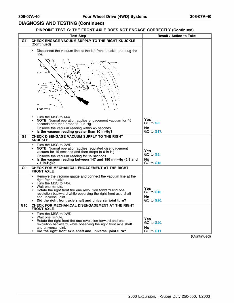
Test Step Result / Action to TakeG7 CHECK ENGAGE VACUUM SUPPLY TO THE RIGHT KNUCKLE
(Continued)
• Disconnect the vacuum line at the left front knuckle and plug theline.
• Turn the MSS to 4X4.Yes• NOTE: Normal operation applies engagement vacuum for 45GO to G8.seconds and then drops to 0 in-Hg.
Observe the vacuum reading within 45 seconds. No• Is the vacuum reading greater than 10 in-Hg? GO to G17.
G8 CHECK DISENGAGE VACUUM SUPPLY TO THE RIGHTKNUCKLE• Turn the MSS to 2WD.• NOTE: Normal operation applies regulated disengagement
Yesvacuum for 15 seconds and then drops to 0 in-Hg.GO to G9.Observe the vacuum reading for 15 seconds.
• Is the vacuum reading between 147 and 180 mm-Hg (5.8 and No7.1 in-Hg)? GO to G18.
G9 CHECK FOR MECHANICAL ENGAGEMENT AT THE RIGHTFRONT AXLE• Remove the vacuum gauge and connect the vacuum line at the
right front knuckle.• Turn the MSS to 4X4.• Wait one minute. Yes• Rotate the right front tire one revolution forward and one GO to G10.revolution backward while observing the right front axle shaft
and universal joint. No• Did the right front axle shaft and universal joint turn? GO to G20.
G10 CHECK FOR MECHANICAL DISENGAGEMENT AT THE RIGHTFRONT AXLE• Turn the MSS to 2WD.• Wait one minute. Yes• Rotate the right front tire one revolution forward and one GO to G20.revolution backward, while observing the right front axle shaft
and universal joint. No• Did the right front axle shaft and universal joint turn? GO to G11.
(Continued)
2003 Excursion, F-Super Duty 250-550, 1/2003

308-07A-41 308-07A-41Four Wheel Drive (4WD) Systems
DIAGNOSIS AND TESTING (Continued)PINPOINT TEST G: THE FRONT AXLE DOES NOT ENGAGE CORRECTLY (Continued)
Test Step Result / Action to TakeG11 CHECK ENGAGE VACUUM SUPPLY TO THE LEFT KNUCKLE
• Remove the plug from the vacuum line at the left front knuckleand install the vacuum gauge on the line.
• Disconnect the vacuum line at the right front knuckle and plugthe line.
YesGO to G12.• Turn the MSS to 4X4.
• NOTE: Normal operation applies engagement vacuum for 45 Noseconds and then drops to 0 in-Hg. CHECK the vacuum harness for damageObserve the vacuum reading for 45 seconds. or an obstruction. REPAIR as necessary.
• Is the vacuum reading greater than 10 in-Hg? TEST the system for normal operation.G12 CHECK DISENGAGE VACUUM SUPPLY TO THE LEFT
KNUCKLE• Turn the MSS to 2WD. Yes• NOTE: Normal operation applies regulated disengagement GO to G13.
vacuum for 15 seconds and then drops to 0 in-Hg. NoObserve the vacuum reading within 15 seconds. CHECK the vacuum harness for damage
• Is the vacuum reading between 5.8 and 7.3 in-Hg? or an obstruction. REPAIR as necessary.TEST the system for normal operation.
G13 CHECK FOR MECHANICAL ENGAGEMENT AT THE LEFTFRONT AXLE• Remove the vacuum gauge and connect the vacuum line at the
left front knuckle.• Turn the MSS to 4X4.• Wait one minute. Yes• Rotate the left front tire one revolution forward and one GO to G14.revolution backward while observing the left front axle shaft and
universal joint. No• Did the left front axle shaft and universal joint turn? GO to G20.
G14 CHECK FOR MECHANICAL DISENGAGEMENT AT THE LEFTFRONT AXLE• Turn the MSS to 2WD.
(Continued)
2003 Excursion, F-Super Duty 250-550, 1/2003
308-07A-42 308-07A-42Four Wheel Drive (4WD) Systems
DIAGNOSIS AND TESTING (Continued)PINPOINT TEST G: THE FRONT AXLE DOES NOT ENGAGE CORRECTLY (Continued)
Test Step Result / Action to TakeG14 CHECK FOR MECHANICAL DISENGAGEMENT AT THE LEFT
FRONT AXLE (Continued)
• Wait one minute. Yes• Rotate the left front tire one revolution forward and one GO to G20.revolution backward while observing the left front axle shaft anduniversal joint. No
• Did the left front axle shaft and universal joint turn? GO to G15.G15 CHECK FOR DYNAMIC VACUUM LEAK AT LF KNUCKLE
• Ignition OFF.• Disconnect the vacuum line at the front knuckle.• Connect a vacuum pump to the knuckle fitting and T in the
vacuum gauge between the knuckle and the pump. Yes• Pump until 20 in-Hg is read. GO to G24.• Rotate the left front tire for 30 seconds while observing vacuumreading. No
• Is the vacuum drop greater than 0.5 in-Hg in 30 seconds? GO to G16.G16 CHECK FOR DYNAMIC VACUUM LEAK AT RF WHEEL
• Ignition OFF.• Disconnect the vacuum line at the right front knuckle. Yes• Connect a vacuum pump to the knuckle fitting and T in the GO to G24.vacuum gauge between the knuckle and the pump.• Pump until 20 in-Hg is read. No• Rotate the right front tire for 30 seconds while observing vacuum The 4X4 system is operating correctly.
reading. INSTRUCT the customer on correct• Is the vacuum drop greater than 0.5 in-Hg in 30 seconds? operation.
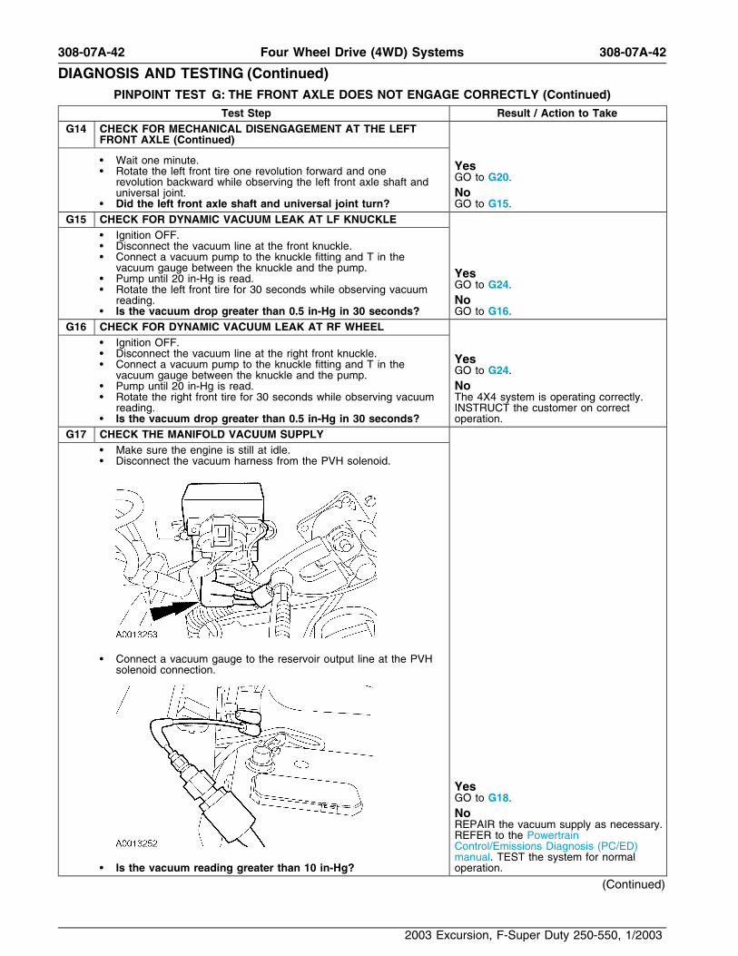
G17 CHECK THE MANIFOLD VACUUM SUPPLY• Make sure the engine is still at idle.• Disconnect the vacuum harness from the PVH solenoid.
• Connect a vacuum gauge to the reservoir output line at the PVHsolenoid connection.
YesGO to G18.NoREPAIR the vacuum supply as necessary.REFER to the PowertrainControl/Emissions Diagnosis (PC/ED)manual. TEST the system for normal
• Is the vacuum reading greater than 10 in-Hg? operation.
(Continued)
2003 Excursion, F-Super Duty 250-550, 1/2003

308-07A-43 308-07A-43Four Wheel Drive (4WD) Systems
DIAGNOSIS AND TESTING (Continued)PINPOINT TEST G: THE FRONT AXLE DOES NOT ENGAGE CORRECTLY (Continued)
Test Step Result / Action to TakeG18 CHECK THE PVH SOLENOID OUTPUT IN 2WD
• Connect the vacuum harness to the PVH solenoid so only thereservoir output line is connected to the solenoid.
• Connect a vacuum gauge to the PVH solenoid output port.
• NOTE: Normal operation applies engagement vacuum for 45 Yesseconds and then drops to 0 in-Hg. GO to G19.Turn the MSS to 4X4 and wait 45 seconds. No
• NOTE: Normal operation applies regulated disengagement INSTALL a new PVH solenoid. REFER tovacuum for 15 seconds and then drops to 0 in-Hg. Pulse Vacuum Hublock (PVH) Solenoid inTurn the MSS to 2WD while observing the vacuum gauge. this section. TEST the system for normal
• Is the vacuum reading between 5.8 and 7.3 in-Hg? operation.G19 CHECK THE PVH SOLENOID OUTPUT IN 4X4
• NOTE: Normal operation applies engagement vacuum for 45 Yesseconds and then drops to 0 in-Hg. CHECK the vacuum harness for leaks,
restrictions, kinks or melted lines. REPAIRTurn the MSS to 4X4 and observe the vacuum reading for 45the vacuum harness as necessary. TESTseconds.the system for normal operation.• Is the vacuum reading greater than 10 in-Hg in 4X4?NoINSTALL a new PVH solenoid. REFER toPulse Vacuum Hublock (PVH) Solenoid inthis section. TEST the system for normaloperation.
G20 CHECK FOR A STATIC VACUUM LEAK• Ignition OFF.• Disconnect the vacuum line at the knuckle.
(Continued)
2003 Excursion, F-Super Duty 250-550, 1/2003

308-07A-44 308-07A-44Four Wheel Drive (4WD) Systems
DIAGNOSIS AND TESTING (Continued)PINPOINT TEST G: THE FRONT AXLE DOES NOT ENGAGE CORRECTLY (Continued)
Test Step Result / Action to TakeG20 CHECK FOR A STATIC VACUUM LEAK (Continued)
• Connect a vacuum pump to the knuckle fitting and T in thevacuum gauge between the knuckle and the pump.
YesGO to G21.• Pump until 20 in-Hg is read.
• Observe the vacuum reading for 30 seconds. No• Is the vacuum drop less than 0.5 in-Hg in 30 seconds? GO to G22.
G21 CHECK FOR A DYNAMIC VACUUM LEAK• Make sure the vacuum is still at 20 in-Hg. Yes• Rotate the front tire for 30 seconds while observing the vacuum INSTALL a new hublock. TEST the system
reading. for normal operation.• Is the vacuum drop less than 0.5 in-Hg in 30 seconds? No
GO to G23.G22 CHECK FOR A LOOSE KNUCKLE FITTING
• Remove the vacuum pump and gauge line from the knuckle.• Make sure the knuckle fitting is tightened to 20 Nm (15 lb-ft).• Install the vacuum pump and gauge line on the knuckle and
pump to 20 in-Hg.
YesIf the right hublock was being tested, GOto G9. If the left hublock was being tested,GO to G13.
• Observe the vacuum reading for 30 seconds. No• Is the vacuum drop less than 0.5 in-Hg in 30 seconds? GO to G23.
G23 CHECK FOR A HUBLOCK O-RING LEAK• Install a known good hublock. Refer to Hublock in this section.
(Continued)
2003 Excursion, F-Super Duty 250-550, 1/2003

308-07A-45 308-07A-45Four Wheel Drive (4WD) Systems
DIAGNOSIS AND TESTING (Continued)PINPOINT TEST G: THE FRONT AXLE DOES NOT ENGAGE CORRECTLY (Continued)
Test Step Result / Action to TakeG23 CHECK FOR A HUBLOCK O-RING LEAK (Continued)
• Install the vacuum pump and gauge line on the knuckle andpump to 20 in-Hg.
YesInstall a new hublock with a new O-ringseal kit. Refer to Hublock in this section
• Observe the vacuum reading for 30 seconds. No• Is the vacuum drop less than 0.5 in-Hg in 30 seconds? GO to G24.
G24 CHECK THE HUBLOCK SEALS• Install the vacuum pump and gauge line on the knuckle fitting
and pump to 20 in-Hg.
YesGO to G25.No
• Observe the vacuum reading for 30 seconds. The 4X4 system is operating correctly.• Is the vacuum drop greater than 0.5 in-Hg in 30 seconds? TEST the system for normal operation.
G25 CHECK THE KNUCKLE SEAL• Install a known good wheel knuckle with a known good hublock.
Refer to Section 204-01B.• Install the vacuum pump and gauge line on the knuckle fitting
and pump to 20 in-Hg.
YesGO to G26.NoINSTALL a new knuckle seal. REFER to
• Observe the vacuum reading for 30 seconds. Section 204-01B. TEST the system for• Is the vacuum drop less than 0.5 in-Hg in 30 seconds? normal operation.
(Continued)
2003 Excursion, F-Super Duty 250-550, 1/2003

308-07A-46 308-07A-46Four Wheel Drive (4WD) Systems
DIAGNOSIS AND TESTING (Continued)PINPOINT TEST G: THE FRONT AXLE DOES NOT ENGAGE CORRECTLY (Continued)
Test Step Result / Action to TakeG26 CHECK FOR A LEAKING HUB ASSEMBLY
• Install the hub assembly with a new O-ring seal.• Install the vacuum pump and gauge line on the knuckle fitting
and pump to 20 in-Hg.
YesREINSTALL the wheel knuckle assemblyand RESTORE the system to normalcondition. REFER to Section 204-01B.VERIFY correct engagement of the 4X4system.NoINSTALL a new wheel knuckle assembly.REFER to Section 204-01B. TEST thesystem for normal operation. If the leakpersists, INSTALL a new hublock. REFER
• Observe the vacuum reading for 30 seconds. to Hublock in this section. TEST the• Is the vacuum drop less than 0.5 in-Hg in 30 seconds? system for normal operation.
G27 CHECK FOR CORRECT MODULE OPERATION• Check for: Yes
INSTALL a new 4WD control module.• corrosion REFER to Four Wheel Drive (4WD)• pushed-out pins Control Module in this section. CLEAR the• Connect any disconnected connectors making sure they are DTCs. REPEAT the self-test.seated correctly.• Make sure all other system connectors are fully seated. No• Operate the system and verify the concern is still present. The system is operating correctly at this• Is the concern still present? time. Concern may have been caused by
a loose or corroded connector. CLEAR theDTCs. REPEAT the self-test.
PINPOINT TEST H: THE 4X4 INDICATOR IS ALWAYS ON—FOUR WHEEL DRIVE SYSTEM OPERATESCORRECTLY
Test Step Result / Action to TakeH1 MONITOR THE 4X4 INDICATOR
• Verify the vehicle is in 2WD. Yes• Observe the 4X4 indicator. REFER Section 206-09 for further• Disconnect the anti-lock brake (ABS) module C104. diagnosis.• Ignition ON. No• Does the 4X4 indicator go off? GO to H2.
H2 CHECK THE 4WD CONTROL MODULE• Disconnect: 4WD Control Module C281b. Yes• Does the 4X4 indicator go off? GO to H4.
NoGO to H3.
H3 CHECK THE INSTRUMENT CLUSTER• Disconnect: Instrument Cluster C220b. Yes• Does the 4X4 indicator go off? REPAIR circuit 210 (LB). TEST the system
for normal operation.NoREPAIR the instrument cluster asnecessary. REFER to Section 413-01.TEST the system for normal operation.
(Continued)
2003 Excursion, F-Super Duty 250-550, 1/2003

308-07A-47 308-07A-47Four Wheel Drive (4WD) Systems
DIAGNOSIS AND TESTING (Continued)PINPOINT TEST H: THE 4X4 INDICATOR IS ALWAYS ON—FOUR WHEEL DRIVE SYSTEM OPERATES
CORRECTLY (Continued)
Test Step Result / Action to TakeH4 CHECK FOR CORRECT MODULE OPERATION
• Check for: YesINSTALL a new 4WD control module.• corrosion REFER to Four Wheel Drive (4WD)• pushed-out pins Control Module in this section. CLEAR the• Connect any disconnected connectors making sure they are DTCs. REPEAT the self-test.seated correctly.
• Make sure all other system connectors are fully seated. No• Operate the system and verify the concern is still present. The system is operating correctly at this• Is the concern still present? time. Concern may have been caused by
a loose or corroded connector. CLEAR theDTCs. REPEAT the self-test.
PINPOINT TEST I: THE 4X4 LOW INDICATOR IS ALWAYS ON
Test Step Result / Action to TakeI1 MONITOR THE 4X4 LOW INDICATOR
• Verify the vehicle is in 2-wheel drive mode. Yes• Observe the 4X4 LOW indicator. GO to I4.• Disconnect: 4WD Control Module C281b.• Ignition ON. No• Does the 4X4 LOW indicator go off? GO to I2.
I2 CHECK THE INSTRUMENT CLUSTER• Disconnect: Instrument Cluster C220b. Yes• Does the 4X4 LOW indicator go off? GO to I3.
NoREPAIR the instrument cluster asnecessary. REFER to Section 413-01.TEST the system for normal operation.
I3 CHECK CIRCUIT 975 (BN/YE) FOR A SHORT TO GROUND• Measure the resistance between 4WD control module C281b pin
8, circuit 975 (BN/YE), harness side and ground.
YesGO to I4.NoREPAIR the circuit. TEST the system for
• Is the resistance greater than 10,000 ohms? normal operation.I4 CHECK FOR CORRECT MODULE OPERATION
• Check for: YesINSTALL a new 4WD control module.• corrosion REFER to Four Wheel Drive (4WD)• pushed-out pins Control Module in this section. CLEAR the• Connect any disconnected connectors making sure they seat DTCs. REPEAT the self-test.correctly.
• Make sure all other system connectors are fully seated. No• Operate the system and verify the concern is still present. The system is operating correctly at this• Is the concern still present? time. Concern may have been caused by
a loose or corroded connector. CLEAR theDTCs. REPEAT the self-test.
2003 Excursion, F-Super Duty 250-550, 1/2003