disaster recovery, business continuity, and backup
TRANSCRIPT

Chapter 12
Disaster Recovery, Business Continuity, and Backup
Disaster Recovery (DR) takes many forms, and the preceding chapter on DRLB covers a small part of DR. Actually, DRLB is more a preventative measure than a prelude to DR. However, although being able to prevent the need for DR is a great goal, too many disasters happen to rely on any one mechanism. In this chapter, we categorize disasters and provide solutions for each one. You will see that the backup tool to use will not dictate how to perform DR, but it’s the other way around. In addition to DR, there is the concept of Business Continu-ity (BC) or the need to keep things running even if a disaster happens. Some of what we discuss in this chapter is BC and not truly DR. However, the two go hand in hand because BC plans are often tied to DR plans and handle a subset of the disasters.
What Is the Goal of Disaster Recovery?
The goal of DR is to either prevent or recovery quickly from downtime caused by either man or nature.
What Is the Goal of Business Continuity or Disaster Avoidance?
The goal of BC is to maintain the business functions in the face of possible downtime caused by man or nature.
As you can see, DR and BC are interrelated: DR is intended to prevent or recover from downtime while BC attempts to maintain business function.
513
12_0137058977_ch12.indd 51312_0137058977_ch12.indd 513 1/18/11 9:09 AM1/18/11 9:09 AM
Chapter 12 Disaster Recovery, Business Continuity, and Backup514
Virtualization provides us the tools to do each of these. In the following discus-sion, unless otherwise stated, ESX and ESXi can be used interchangeably.
Disaster Types
There are various forms of well-defined disasters and ways to prevent or work around these to meet the defined goal. There is no one way to get around disas-ters, but knowing they exist is the first step in planning for them. Having a DR or BC plan is the first step toward prevention, implementation, and reduction in downtime. At a conference presentation, I asked a room of 200 customers if any of them had a DR or BC plan. Only two people stated they had a DR or BC plan, which was disconcerting but by no means unexpected.
Best Practice for DR and BC
Create a written DR and BC plan.
Writing the DR and BC plan will help immensely, in the case that it is needed, because there will be absolutely no confusion about it in an emergency situation. For one customer, the author was requested to make a DR plan to cover all pos-sible disasters. Never in the customer’s wildest dreams did they think it would need to be used. Unfortunately, the “wildest dream” scenario occurred, and the written DR plan enabled the customer to restore the environment in an orderly fashion extremely quickly. It is in your best interest to have a written DR plan that covers all possible disasters to minimize confusion and reduce downtime when, and not if, a disaster occurs.
Best Practice for DR and BC
Plan for failure; do not fail to plan.
Yes, this last best practice sounds like so many other truisms in life, but it is definitely worth considering around DR and BC, because failures will occur with surprising frequency, and it is better to have a plan than everyone running around trying to do everything at once. So what should be in a DR and BC plan? First, we should understand the types of disasters possible and use these as a basis for a DR and BC plan template. Granted, some of the following examples are scary and unthinkable, but they are not improbable. It is suggested that you use the following list and add to it items that are common to your region of the world as a first step to understanding what you may face when you start
12_0137058977_ch12.indd 51412_0137058977_ch12.indd 514 1/18/11 9:09 AM1/18/11 9:09 AM

Disaster Types 515
a DR or BC plan. A customer I consulted for asked for a DR plan, and we did one considering all the following possibilities. When finished, we were told that a regional disaster was not possible and that it did not need to be considered. Unfortunately, Katrina happened, which goes to show that if we can think it up, it is possible. Perhaps a disaster is improbable, but nature is surprising.
Disasters take many forms. The following list is undoubtedly not exhaustive, but it includes many different types of potential disasters.
• Application failure
An application failure is the sudden death of a necessary application, which can be caused by poorly coded applications and are exploited by denial-of-service (DoS) attacks that force an application to crash.
• VM failure
A VM failure could be man-made, by nature, or both. Consider the man-made possibilities such as where a security patch needs to be applied or software is to be added to the VM. By nature could be the failure of the VM due to an OS bug, an unimplemented procedure within the virtualiza-tion layer, or an application issue that used up enough resources to cause the VM to crash. In general, VM failures are unrelated to hardware be-cause the virtualization layer removes the hardware from the equation. But it does not remove OS bugs from the equation.
• ESX host failure
A machine failure can be man-made, by nature, or even both. For exam-ple, a man-made failure could be the planned outage to upgrade firmware, hardware, the ESX OS, or the possible occurrence of a hardware failure of some sort that causes a crash. Another example is if power is inadvertently shut off to the server.
• Communication failure
A communication failure is unrelated to ESX, but will affect ESX nonethe-less. Communication can be via Fibre Channel, Ethernet, or for such items as VMCI, VMsafe, VIX, and so on via some out-of-band mechanism. The errors could be related to a communication card, cable, switch, or a device at the non-ESX side of the communication. An example of this type of failure is a Fibre or network cable being pulled from the box or a switch is powered off or rebooted.
12_0137058977_ch12.indd 51512_0137058977_ch12.indd 515 1/18/11 9:09 AM1/18/11 9:09 AM

Chapter 12 Disaster Recovery, Business Continuity, and Backup516
• Chassis failure
Chassis failures can cause either a single host to fail or multiple hosts to fail. As datacenters become denser, more and more blade and other shared hardware chassis come into play. This could simply be a failure of a single fan to the back or mid plane components failing outright. This type of fail-ure could cause many ESX hosts to fail or have a communication failure that could affect more than one host.
• Rack disaster
Rack failures are extremely bad and are often caused by the rack being moved around or even toppling over. Not only will such an incident cause failures to the systems or communications, but it could cause physical in-jury to someone caught by the rack when it topples. Another rack failure could be the removal of power to fans of and around the whole rack, causing a massive overheat situation where all the servers in the rack fail simultaneously.
• Datacenter disaster
Datacenter disasters include air conditioning failures that cause overheat-ing, power spikes, lack of power, earthquakes, floods, fire, and anything else imaginable that could render the datacenter unavailable. An example of this type of disaster is the inadvertent triggering of a sprinkler system or a sprinkler tank bursting and flooding the datacenter below. It may seem odd, but some datacenters still use water and no other flame prevention system. Use of halon and other gasses can be dangerous to human life and, therefore, these gasses may not be used.
• Building disaster
Like datacenter disasters, these disasters cause the building to become un-tenable. These include loss of power or some form of massive physical destruction. An example of this type of disaster is what happened to the World Trade Center.
• Campus disaster
Campus disasters include a host of natural and man-made disasters where destruction is total. An example of this type of disaster is tornadoes, which may strike one place and skip another but can render to rubble anything in its path.
12_0137058977_ch12.indd 51612_0137058977_ch12.indd 516 1/18/11 9:09 AM1/18/11 9:09 AM
Recovery Methods 517
• Citywide disaster
Citywide disasters are campus disasters on a much larger scale. In some cases, the town is the campus (as is the case for larger universities). Exam-ples range from earthquakes, to hurricanes, to atomic bombs.
• Regional disaster
Regional disasters include massive power outages similar to the blackout in the New England area in 2003 and hurricanes such as Katrina that cover well over 200 miles of coastline.
• National disasters
For small countries, such as Singapore or Luxembourg, a national disaster is equivalent to a citywide disaster and could equate to a regional disaster. National disasters in larger countries may be unthinkable, but it is not impossible.
• Multinational disaster
Again, because most countries touch other countries and there are myriad small countries all connected, this must be a consideration for planning. Tsunamis, earthquakes, and other massive natural disasters are occurring around us. Another option is a massive planned terrorist attack on a single multinational company.
• World disaster
This sort of disaster is unthinkable and way out of scope!
Recovery Methods
Now that the different levels of disasters are defined, a set of tools and skills necessary to recover from each one can be determined. The tools and skills will be specific to ESX and will outline physical, operational, and backup method-ologies that will reduce downtime or prevent a disaster:
• Application failure
The recovery mechanism for a failed application is to have some form of watchdog that will launch the application anew if it was detected to be down. Multiple VMs running the same application connected to a net-work load balancer will also help in this situation by reducing the traffic to any one VM, and hence the application, and will remove application from
12_0137058977_ch12.indd 51712_0137058977_ch12.indd 517 1/18/11 9:09 AM1/18/11 9:09 AM
Chapter 12 Disaster Recovery, Business Continuity, and Backup518
the list of possible targets if it is down. Many of these types of clusters also come with ways of restarting applications if they are down. Use of shared data disk clustering à la Microsoft clusters is also a possible solution.
• VM failure
Recovery from a VM failure can be as simple as rebooting the VM in ques-tion via some form of watchdog such as VMware HA VM Monitoring or VMware FT. However, if the VM dies, it is often necessary to determine why the problem occurred, and therefore this type of failure often needs debugging. In this case, the setup of VMware FT or some form of shared data disk cluster à la Microsoft clusters will allow a secondary VM to take over the duties of the failed VM. Any VM failure should be investigated to determine the cause. Another mechanism is to have a secondary VM ready and waiting to take over duties if necessary. If the data of the primary VM is necessary to continue, consider placing the data on a second VMDK and have both VMs pointing to the second disk. Just make sure that only one is booted at the same time. Use DRLB tools to automatically launch this secondary VM if necessary.
With VMware FT, this last suggestion may seem unnecessary, but if there is a Guest OS or application failure the shadow VM created by FT may also fail as the primary VM and shadow VM are in vLockStep.
• Machine failure
Hardware often has issues. To alleviate machine failures have a second machine running and ready to take on the load of the first machine. Use VMware HA or other high-availability tools to automatically specify a host on which to launch the VMs if a host fails. In addition, if you know the host will fail due to a software or hardware upgrade, first vMotion all the VMs to the secondary host. VMware HA can be set up when you create a VMware cluster or even after the fact. We discussed the creation of VMware clusters in Chapter 11 , “Dynamic Resource Load Balancing.” VMware HA makes use of the Legato Automated Availability Manage-ment (Legato AAM) suite to manage the ESX host cluster failover. There is more on HA later in this chapter in the section “Business Continuity.”
VMware DPM, used in conjunction with VMware HA and VMware DRS, would enable another machine to act as a hot spare. This would of course require one node (usually the +1 node) to be in a rack, installed, kept up-dated, and otherwise ready to be used as dictated by VMware DRS.
12_0137058977_ch12.indd 51812_0137058977_ch12.indd 518 1/18/11 9:09 AM1/18/11 9:09 AM
Recovery Methods 519
• Communication failure
Everyone knows that Fibre and network connections fail, so ensure that multiple switches and paths are available for the communications to and from the ESX host. In addition, make local copies of the most important VMs so that they can be launched using a local disk in the case of a SAN failure. This often requires more local disk for the host and the avoidance of booting from SAN.
• Chassis disaster
To avoid devastating chassis disasters, it is best to divide your most impor-tant VMs between multiple chassis but also maintaining enough headroom on all blades within a chassis so that if VMware HA needs to be used, the VMs have a home on a new chassis. In large datacenters, it may be useful to have a hot spare chassis with blades in it waiting to be used via VMware DRS and DPM or one that is ready to accept blades.
• Rack disaster
To avoid a rack disaster, make sure racks are on earthquake-proof stands, are locked in place, and perhaps have stabilizers deployed. But also be sure that your ESX hosts and switches are divided and placed into separate racks in different locations on the datacenter floor, so that there is no catastrophic failure and that if a rack does fail, everything can be brought back up on the other rack.
• Datacenter disaster
To avoid datacenter disasters, add more hosts to a secondary datacenter either in the same building or elsewhere on the campus. Often this is re-ferred to as a hot site and requires an investment in new SAN and ESX hosts. Also ensure there are adequate backups to tape secured in a vault. In addition, it is possible with ESX version 3 to vMotion VMs across subnets via routers. In this way, if a datacenter was planned to go down, it would be possible to move running VMs to another datacenter where other hosts reside.
VMware Site Recovery Manager (SRM) is one tool that can be used to maintain a hot site as could Veeam Backup or Vizioncore vReplicator.
EMC’s VPLEX technology could also be used to maintain consistent writes between two different datacenters no more than 60km away. VPLEX offers the capability to maintain a complete synchronous backup of data on two different and distinct storage subsystems. EMC VPLEX with vTeleport could even move VMs from datacenter to datacenter as
12_0137058977_ch12.indd 51912_0137058977_ch12.indd 519 1/18/11 9:09 AM1/18/11 9:09 AM
Chapter 12 Disaster Recovery, Business Continuity, and Backup520
needed. Granted, as we discussed in Chapter 5 , “Storage with ESX,” use of vTeleport (long distance vMotion) requires a stretched Layer-2 network between the datacenters.
• Building disaster
The use of a hot site and offsite tape backups will get around building dis-asters. Just be sure the hot site is not located in the same building.
EMC VPLEX and vTeleport would also allow for a solid BC by maintain-ing both datacenters in a synchronous model.
• Campus disaster
Just like a building disaster, just be sure the other location is off the campus.
• Citywide disaster
Similar to campus disasters, just be sure the hot site or backup location is outside the city.
• Regional disaster
Similar to campus disasters, just be sure the hot site or backup location is outside the region.
• National disasters
Similar to campus disasters, just be sure the hot site or backup location is outside the country, or if the countries are small, in another country far away.
• Multinational disasters
Because this could be considered a regional disaster in many cases, see the national DR strategy.
• World disasters
We can dream some here and place a datacenter on another astronomical body or space station.
The major tools to use for DR and BC follow:
• Application Monitoring
• VMware Fault Tolerance or VMware HA VM Monitoring
12_0137058977_ch12.indd 52012_0137058977_ch12.indd 520 1/18/11 9:09 AM1/18/11 9:09 AM

Best Practices 521
• VMware HA, DRS, and DPM all working together with the use of hot spare systems or chassis
• VMware SRM, Veeam Backup, PhD Virtual Backup, or Vizioncore vRep-licator
• EMC VPLEX with vTeleport
Best Practices
Now that the actions to take for each disaster are outlined, a list of best practices can be developed to define a DR or BC plan to use. The following list considers an ESX host, from a single host to enterprisewide, with DR and BC in mind. The list covers mainly ESX, not all the other parts to creating a successful and highly redundant network. The list is divided between local practices and re-mote practices. This way the growth of an implementation can be seen. The idea behind these best practices is to look at our list of possible failures and to have a response to each one and to know that many eggs are being placed into one basket. On average for larger machines, ESX hosts can house 20+ VMs. That is a lot of service that could go down if a disaster happens.
First, we need to consider the local practices around DR:
• Implement ESX using N+1 hosts where N is the necessary number of hosts to run the VMs required. The extra host is used for DR.
• When racking the hosts, ensure that hosts are stored in different racks in different parts of the datacenter.
• Be sure there are at least two Fibre Channel (FC) cards, if employing FC SAN, using different PCI buses if possible.
• Be sure there are at least two NIC ports for each network to be attached to the host using different PCI buses if possible.
• When cabling the hosts, ensure that redundant cables go to different switches and that no redundant path uses the same PCI card.
• Be sure that all racks are stabilized.
• Be sure that there is enough cable available so that machines can be fully extended from the rack as necessary.
• Ensure there is enough local disk space to store exported versions of the VMs and to run the most important VMs if necessary.
12_0137058977_ch12.indd 52112_0137058977_ch12.indd 521 1/18/11 9:09 AM1/18/11 9:09 AM
Chapter 12 Disaster Recovery, Business Continuity, and Backup522
• Ensure HA is configured so that VMs running on a failed host are auto-matically started on another host.
• Use storage replication (VPLEX, SRM, and the like) to ensure SANs are redundant, either within the same datacenter or across datacenters.
• Create DRLB scripts to start VMs locally if SAN connectivity is lost.
• Create DRLB scripts or enable VMware DRS to move VMs when all re-sources loads are too high on a single host.
Second, we need to consider the remote practices around DR:
• When creating DR backups, ensure there is safe storage for tapes onsite and offsite.
• Follow all the local items, listed previously, at any remote sites.
• Create a list of tasks necessary to be completed if there is a massive site failure. This list should include who does what and the necessary depend-encies for each task.
The suggestions translate into more physical hardware to create a redundant and safe installation of ESX. It also translates into more software and licenses, too. Before going down the path of hot sites and offsite tape storage, the local DR plan needs to be fully understood from a software perspective, specifically the methods for producing backups, and there are plenty of methods. Some methods adversely impact performance; others do not. Some methods and secu-rity controls lend themselves to expansion to hot sites, and others will take sneaker nets and other mechanisms to get the data from one site to the other.
Backup and Business Continuity
The simplest approach to DR is to make a good backup of everything so that restoration is simplified when the time comes, but backups can happen in two distinctly different ways with ESX. In some cases, some of these suggestions do not make sense because the application in use can govern how things go. As an example, we were asked to look at DR backup for an application with its own built-in DR capabilities with a DR plan that the machine be reinstalled on new hardware if an issue occurred. The time to redeploy in their current environment was approximately an hour, and it took the same amount of time for a full DR backup through ESX. Because of this, the customer decided not to go with full DR backups.
12_0137058977_ch12.indd 52212_0137058977_ch12.indd 522 1/18/11 9:09 AM1/18/11 9:09 AM
Backup and Business Continuity 523
Backup
What is a full DR backup? As stated previously, there are two major backup styles. The first, in terms of ESX, is referred to as a backup for individual file restoration or a backup made from within the VM. The second is a DR-level backup of the full VM disk image and configuration file. The difference is the restoration method. A standard backup, using agents running within the VM, usually follows these steps for restoration:
1. Install OS onto machine.
2. Install restoration tools.
3. Test restoration tools.
4. Restore system.
5. Test restoration.
A full DR-level backup has the following restoration process:
1. Restore VMDK and configuration file.
2. Register VM into ESX.
3. Boot VM.
As you can see, the restoration process for a full DR backup is much faster than the normal method, which in many cases makes a DR backup more accept-able, but it generally requires more hardware. But what hardware is really the question, and one that needs to be considered for ESX. A standard ESX stan-dalone ESX host consists of lots of memory and as much disk as can be placed into the server. A standard remote datastore–attached ESX host consists of lots of memory and very little local disk space, and a boot from SAN (BFS) ESX host usually has no local disk space, which is not a best practice, as outlined in Chap-ter 3 , “Installation.” Our best practice for installing ESX outlines a need for local storage on which safe backups and ready-to-use backups could be placed.
There are few ways to create backups, and the methods are similar no mat-ter where the data will eventually reside. DR backups can be made many ways using an equally different number of tools: VMware Data Recovery (VDR), VMware Consolidated Backup (VCB), and one of the other third-party tools. The goal is to eventually place the data on a tape device, local storage, remote storage, or a remote hot site for restoration of full VMDKs, bringing up VMs at a hot site or even file level restore. File restore backups can be made using VDR, VCB, and other third-party backup agents.
12_0137058977_ch12.indd 52312_0137058977_ch12.indd 523 1/18/11 9:09 AM1/18/11 9:09 AM

Chapter 12 Disaster Recovery, Business Continuity, and Backup524
Backup Paths The choice of which tool to use depends entirely on the backup patch you choose to use. Some paths, as we shall see, are product specific whereas others span multiple products.
Path 1 Path 1, featured in Figure 12.1 , represents a common backup approach for all versions of ESX but not ESXi. This approach still provides a level of redundancy that protects a system from catastrophic SAN or NAS failures. This is a full DR-level backup:
• VMs are exported from the remote VMFS to the backup storage location, which can be anything the ESX host Service Console can see: CIFS, NFS, FTP, SCP, and so on. If the backup storage location is on another network use of a secure copy mechanism is recommended.
• The most important VMs are copied to a local VMFS (usually the tool in use would first copy from the remote VMFS to the local VMFS and then out to the backup storage).
• A remote backup server can then send the data to tape storage or any-where else within the public or private cloud.
Figure 12.1 Path 1
Path 2 Path 2, featured in Figure 12.2 , represents the Path 1 approach for all versions of VMware ESXi. This approach like Path 1 provides a level of redundancy that protects a system from catastrophic SAN or NAS failures.
12_0137058977_ch12.indd 52412_0137058977_ch12.indd 524 1/18/11 9:09 AM1/18/11 9:09 AM

Backup and Business Continuity 525
• VMs are exported from the remote VMFS to the backup storage location, using the vifs --get command.
• VMs can then be imported to a local VMFS from the backup storage loca-tion using the vifs -–put command.
• A remote backup server can then send the data to tape storage or any-where else within the public or private cloud.
Figure 12.2 Path 2
Path 3 Path 3, featured in Figure 12.3 , represents the use of the vStorage API either a VCB or VDR proxy server. VCB installs on Windows 2003 or 2008. When us-ing VCB, this can also be a full file level backup if the file system of the Guest OS is understood by the Windows 2003 or 2008 proxy server, which can also be a VM. With VDR, which is already a VM, the same holds true:
• The remote storage datastores are mounted onto the proxy server either directly from the SAN or NAS device or via a network link (dashed line in Figure 12.3 ), which implies the backup travels through the service console or management appliance.
• When the VMDK is exported or the per-file backup is finished, the proxy server unmounts the VMDKs of the VM.
• The data is then sent to tape or a tape server or anywhere else within the public or private cloud from the proxy server.
12_0137058977_ch12.indd 52512_0137058977_ch12.indd 525 1/18/11 9:09 AM1/18/11 9:09 AM
Chapter 12 Disaster Recovery, Business Continuity, and Backup526
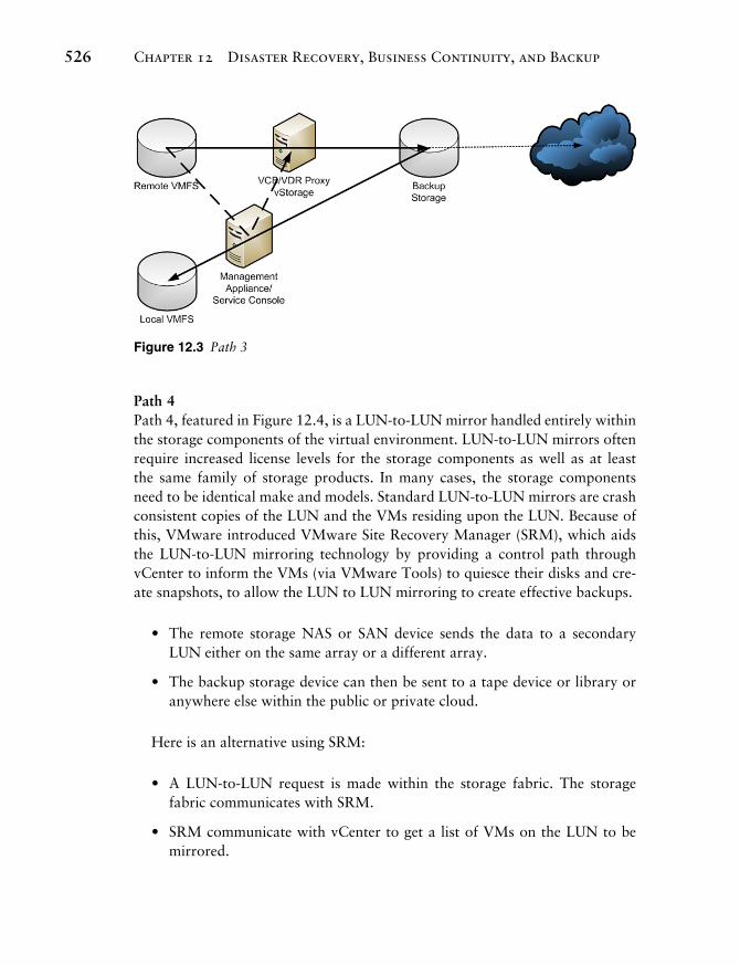
Figure 12.3 Path 3
Path 4 Path 4, featured in Figure 12.4 , is a LUN-to-LUN mirror handled entirely within the storage components of the virtual environment. LUN-to-LUN mirrors often require increased license levels for the storage components as well as at least the same family of storage products. In many cases, the storage components need to be identical make and models. Standard LUN-to-LUN mirrors are crash consistent copies of the LUN and the VMs residing upon the LUN. Because of this, VMware introduced VMware Site Recovery Manager (SRM), which aids the LUN-to-LUN mirroring technology by providing a control path through vCenter to inform the VMs (via VMware Tools) to quiesce their disks and cre-ate snapshots, to allow the LUN to LUN mirroring to create effective backups.
• The remote storage NAS or SAN device sends the data to a secondary LUN either on the same array or a different array.
• The backup storage device can then be sent to a tape device or library or anywhere else within the public or private cloud.
Here is an alternative using SRM:
• A LUN-to-LUN request is made within the storage fabric. The storage fabric communicates with SRM.
• SRM communicate with vCenter to get a list of VMs on the LUN to be mirrored.
12_0137058977_ch12.indd 52612_0137058977_ch12.indd 526 1/18/11 9:09 AM1/18/11 9:09 AM

Backup and Business Continuity 527
• SRM communicates with vCenter to have it inform the VMs on the LUN to quiesce their disks and create snapshots (hopefully on separate LUNs).
• SRM informs the array to perform the LUN-to-LUN mirror. SRM then informs vCenter after the mirror is complete to commit the snapshots to the VMs.
• The backup storage device can then be sent to a tape device or library or anywhere else within the public or private cloud.
Figure 12.4 Path 4
Additional Hot Site Backup Paths Figure 12.4 also demonstrates one method to create a hot site from the original ESX environment. A hot site is limited in distance by the technology used to copy data from one location to another. There are three methods to copy data from site to site: via Fibre, via network, and via sneaker. In addition to the four existing paths, we can now add the paths covered in this section. In addition to the LUN-to-LUN mirror or copy, we can add the following paths.
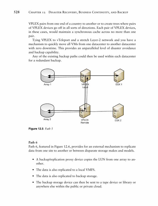
Path 5 Path 5, featured in Figure 12.5 , represents the use of EMC VPLEX to maintain synchronous storage cache between two distinct datacenters (or storage arrays) no more than 100 miles (60 km) apart. In essence, writes on one VPLEX are transmitted to the VPLEX paired with it. The distance apart will depend entirely on the network latency between the two VPLEX devices: more latency may im-ply shorter distances.
The storage that sits behind a VPLEX does not need to be alike storage; they could be different makes and models, unlike LUN mirroring. Because of this, it is theoretically possible to put a VPLEX behind a VPLEX and either chain
12_0137058977_ch12.indd 52712_0137058977_ch12.indd 527 1/18/11 9:09 AM1/18/11 9:09 AM
Chapter 12 Disaster Recovery, Business Continuity, and Backup528
VPLEX pairs from one end of a country to another or to create trees where pairs of VPLEX devices go off in all sorts of directions. Each pair of VPLEX devices, in these cases, would maintain a synchronous cache across no more than one pair.
Tying VPLEX to vTeleport and a stretch Layer-2 network and you have a mechanism to quickly move all VMs from one datacenter to another datacenter with zero downtime. This provides an unparalleled level of disaster avoidance and backup capability.
Any of the existing backup paths could then be used within each datacenter for a redundant backup.
Figure 12.5 Path 5
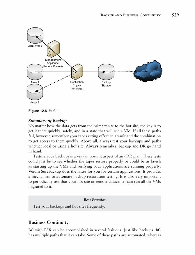
Path 6 Path 6, featured in Figure 12.6 , provides for an external mechanism to replicate data from one site to another or between disparate storage makes and models.
• A backup/replication proxy device copies the LUN from one array to an-other.
• The data is also replicated to a local VMFS.
• The data is also replicated to backup storage.
• The backup storage device can then be sent to a tape device or library or anywhere else within the public or private cloud.
12_0137058977_ch12.indd 52812_0137058977_ch12.indd 528 1/18/11 9:09 AM1/18/11 9:09 AM
Backup and Business Continuity 529
Figure 12.6 Path 6
Summary of Backup No matter how the data gets from the primary site to the hot site, the key is to get it there quickly, safely, and in a state that will run a VM. If all these paths fail, however, remember your tapes sitting offsite in a vault and the combination to get access to them quickly. Above all, always test your backups and paths whether local or using a hot site. Always remember, backup and DR go hand in hand.
Testing your backups is a very important aspect of any DR plan. These tests could just be to see whether the tapes restore properly or could be as lavish as starting up the VMs and verifying your applications are running properly. Veeam SureBackup does the latter for you for certain applications. It provides a mechanism to automate backup restoration testing. It is also very important to periodically test that your hot site or remote datacenter can run all the VMs migrated to it.
Best Practice
Test your backups and hot sites frequently.
Business Continuity
BC with ESX can be accomplished in several fashions. Just like backups, BC has multiple paths that it can take. Some of these paths are automated, whereas
12_0137058977_ch12.indd 52912_0137058977_ch12.indd 529 1/18/11 9:09 AM1/18/11 9:09 AM
Chapter 12 Disaster Recovery, Business Continuity, and Backup530
others require human intervention. One of the ideas behind BC is to provide a way for the business to continue uninterrupted and the VMware cluster technol-ogy provides a part of this by the implementation of VMware DRS, VMware FT, and VMware HA. Where DR-level backups are generally geared toward the re-creation of the environment, BC is the application of clustering technology to prevent the need for such time-consuming restoration. This is achieved using VMware HA, DRS, FT, and vTeleport using stretch Layer-2 networks and EMC VPLEX but also through the use of preconfigured hot sites that can come online in a fraction of the full restoration time. These concepts are discussed within Chapter 11 .
Our methods discussed at the beginning of this chapter implement hot sites by using replication and synchronous storage cache. However, hot servers or servers in the datacenter that do not do anything until they are needed are other options, which are ready to power on using VMware DPM. VMware DRS with DPM covers this latter case. VMware HA is a high-availability-based solu-tion that will, when an ESX host crashes, boot the VMs running there onto other ESX hosts either randomly (according to VMware DRS rules) or by using defined placement and boot order rules. VMware FT allows a shadow VM to be running alongside the parent VM. If the parent VM fails or the host on which it lives fails, the shadow VM takes over. These technologies cover the needs of BC.
Outside of VMware DRS, HA, and FT a myriad of other BC options are available. These include having as many redundant components as possible in different places within the datacenter, building, or campus, and there are mul-tiple paths to all these devices from the ESX hosts. This leads to a much higher cost in and availability of hardware, but it will be the difference between a short service interruption and an absolute disaster. Consider the case of an ESX host crashing with smoke pouring out of a vent. If you had invested in VMware HA, the software would automatically boot the VMs on another system while VMware DRS would load balance the VMs if there is CPU or memory conten-tion. If DPM is available a hot-spare host could take over some the load without the need for human intervention. Or if the VMs were limited sufficiently to use VMware FT, the shadow VMs would automatically take over without the delay of rebooting. On the other hand if you purchased a HP C-class blade in a RAID blade configuration the ESX host would fail over using a complete hardware solution. This leads to the question of which is better: hardware or software solutions? And the answer is, as always, it depends on the cost benefit. This same HP C-class blade has one limitation, the designated RAID blade must be in the same chassis of the failing node, and they must both share disks on a disk blade. This limits the amount of processing power to the blade chassis; and what happens if the chassis itself fails?
Many sites keep identical preinstalled hardware locked in a closet to solve some of these problems. However, it is your disaster to recover from, so think
12_0137058977_ch12.indd 53012_0137058977_ch12.indd 530 1/18/11 9:09 AM1/18/11 9:09 AM
The Tools 531
of all the solutions and draft the plan for both DR and BC appropriate for your environment. Any plan should include all aspects of BC, including
• How long it takes for a hot site to boot
• What steps to take to bring up a hot site
• The steps to take if a natural disaster is heading in your direction (such as a hurricane)
In essence, you need a run-book that covers all contingency plans with respect to DR and BC.
The Tools
Now that the theory is explained, what tools are available for performing the tasks? Although each family of enterprise class remote storage has its own names for the capability to make LUN-to-LUN copies, refer to the VMware SAN com-patibility documentation to determine what is and is not supported, because it might turn out that the hot-copy mechanism for your SAN is not supported by any version of ESX. If VMware SRM is supported with your storage device, this is the recommended way to go.
Best Practice
When choosing to use LUN-to-LUN copies, ensure that your SAN or NAS is supported by SRM.
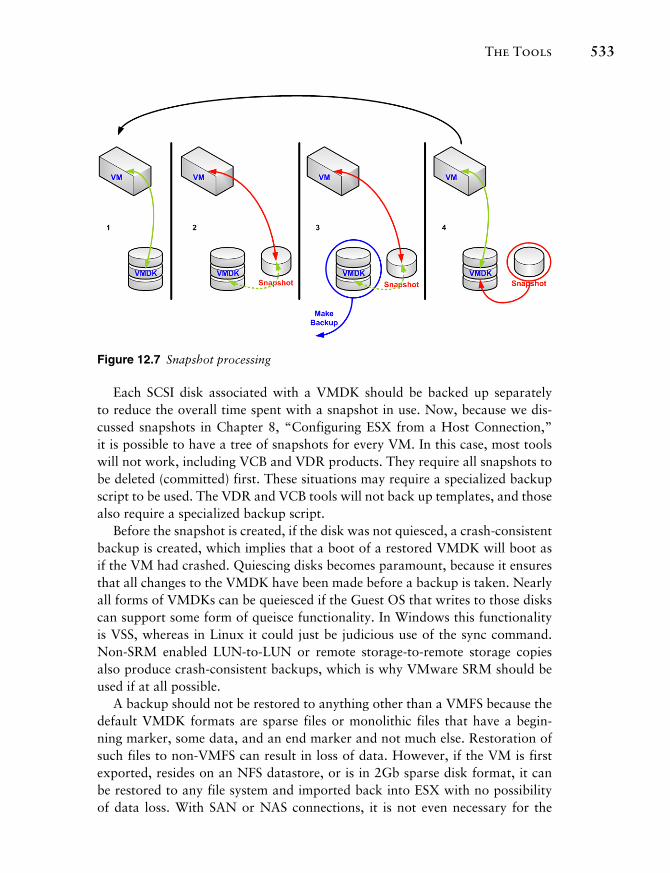
Beyond the remote storage-to-remote storage copies, many other tools are available from VMware and various vendors. All these tools must first take a snapshot of a VM, which changes the file to which disk writes occur so that the backup software can make a copy of the parent VMDK. Figure 12.7 shows the process by which a snapshot is used to make a backup:
1. At this stage, the VM is running normally, writing to the proper VMDK.
2. A snapshot has been requested, the VMDK is quiesced, and the snapshot is created. The existing write traffic to the VMDK is redirected to the snap-shot, which records only changed blocks from the VMDK. Read actions read through the snapshot to the VMDK as needed (the dotted line).
12_0137058977_ch12.indd 53112_0137058977_ch12.indd 531 1/18/11 9:09 AM1/18/11 9:09 AM
Chapter 12 Disaster Recovery, Business Continuity, and Backup532
3. The backup of the VMDK is taken while all new or changed data is written to the snapshot.
4. The original read/write path to the VMDK is once more established and the changes stored within the snapshot are committed to the VMDK, and the snapshot is once more deleted.
5. We are back with a normally running VM.
A snapshot contains only the changed blocks from the primary VMDK, so a snapshot can never grow larger than the parent VMDK. As such it maintains a list or map of changed blocks. Change Block Tracking (CBT) makes use of this map to determine exactly what blocks have changed from the parent VMDK. CBT is available via the vStorage API. CBT is also used within backup tools when creating incremental backups to reduce the overall transfer of data. It is far more efficient to use the existing CBT map than to try and create a list of blocks that changed during the backup procedure. Some of the backup tools go one step further and use Active Block Management (ABM) that combines CBT with the capability to inquire of the actual filesystem what blocks repre-sent deleted data or whitespace so that the list of blocks to back up is further reduced. Even within the CBT capability, ABM will make a huge difference in backup times by removing those blocks of data that do not require backups.
When the backup is made of the VMDK or Virtual RDM in step 3, the disk is usually hot-added to a backup appliance so that the backup appliance (which runs as a VM in many cases) can bypass any network mechanism to access the virtual disk’s data. This increases overall performance. However, backups are disk intensive and if your storage device already has issues, adding a backup device to it would not be a good idea. This is where specialized scripts that can use Storage vMotion to move a VMDK to a lesser-used LUN would come in handy. Unfortunately, Storage DRS has been demoed, but has not been made available.
Another useful tool in the backup/replication toolbox is the use of deduplica-tion. Deduplication is used on SAN and NAS arrays to combine blocks of disk that are identical into a single block with a reference to that block within the chain of blocks associated with a file. Deduplication within a backup/replication tool is designed to limit not only what gets written to disk but what is trans-ferred over the network links in use.
12_0137058977_ch12.indd 53212_0137058977_ch12.indd 532 1/18/11 9:09 AM1/18/11 9:09 AM
The Tools 533
Figure 12.7 Snapshot processing
Each SCSI disk associated with a VMDK should be backed up separately to reduce the overall time spent with a snapshot in use. Now, because we dis-cussed snapshots in Chapter 8 , “Configuring ESX from a Host Connection,” it is possible to have a tree of snapshots for every VM. In this case, most tools will not work, including VCB and VDR products. They require all snapshots to be deleted (committed) first. These situations may require a specialized backup script to be used. The VDR and VCB tools will not back up templates, and those also require a specialized backup script.
Before the snapshot is created, if the disk was not quiesced, a crash-consistent backup is created, which implies that a boot of a restored VMDK will boot as if the VM had crashed. Quiescing disks becomes paramount, because it ensures that all changes to the VMDK have been made before a backup is taken. Nearly all forms of VMDKs can be queiesced if the Guest OS that writes to those disks can support some form of queisce functionality. In Windows this functionality is VSS, whereas in Linux it could just be judicious use of the sync command. Non-SRM enabled LUN-to-LUN or remote storage-to-remote storage copies also produce crash-consistent backups, which is why VMware SRM should be used if at all possible.
A backup should not be restored to anything other than a VMFS because the default VMDK formats are sparse files or monolithic files that have a begin-ning marker, some data, and an end marker and not much else. Restoration of such files to non-VMFS can result in loss of data. However, if the VM is first exported, resides on an NFS datastore, or is in 2Gb sparse disk format, it can be restored to any file system and imported back into ESX with no possibility of data loss. With SAN or NAS connections, it is not even necessary for the
12_0137058977_ch12.indd 53312_0137058977_ch12.indd 533 1/18/11 9:09 AM1/18/11 9:09 AM
Chapter 12 Disaster Recovery, Business Continuity, and Backup534
host that creates the VM snapshot to be the host that actually does the backup. This generally requires extra scripting, but it is possible for a host that is run-ning the VM to create the VM snapshot and then signal a backup host that the backup can be made. When the backup is completed, another signal is made to the running host to commit the snapshot. In this way, the backup host offloads the work from the running ESX host. The signals could even be reversed so that the backup host does all the work and calls the running host only as necessary.
Modern virtual disk backup tools from Veeam, Vizioncore, PHD Virtual, and VMware have removed the need for “by hand” scripting from the require-ments since ESX v3 days. However, many companies still have backup scripts in use that tie into these other products to drop the backed-up data to tape. Tapes can be accessed from VMs, which would pin the VM to a given host, making BC difficult to achieve for the pinned VM.
Local Tape Devices
Local tape devices and libraries require two things: a specific Adaptec SCSI HBA and software to control the robot or tape, ansd a VM to which to connect the tape via SCSI pass-thru mode. When there is a problem with the local tape or tape library device, the ESX host often has to be rebooted, and although it is possible to remove and reload the appropriate kernel module, some devices are not fully reconfigured unless they are seen at boot time. Using tape devices and libraries attached to remote archive servers is the recommended choice if possible.
Best Practices for Local Tape Devices
Do not use local tape devices; if it becomes absolutely necessary, be sure to understand the impact on the local ESX host and plan VM deployments accordingly.
VMware Data Recovery
VMware Data Recovery is a follow on to VMware Consolidated Backup. Un-like VCB, VDR does not require a Windows host or VM on which to run. It is a self-contained virtual appliance with a Data Recovery Client plug-in to the vSphere Client to aid in management and use of VDR. VDR is actually Linux based, which simplifies licensing concerns. The VDR appliance ships as an ISO image as of v1.2 that contains both the OVF formatted appliance and the Data Recovery Client Plug-in. Import of the OVF is as described in Chapter 10 ,
12_0137058977_ch12.indd 53412_0137058977_ch12.indd 534 1/18/11 9:09 AM1/18/11 9:09 AM
The Tools 535
“Virtual Machines.” The Data Recovery Client plug-in installs like any other Windows application and should be installed on the server on which you are running the vSphere Client that must be a windows machine.
There is, however, a Restoration module that will run on Linux or Windows for your use, so be sure to install this tool as well where appropriate.
VDR has a few limits:
• Will back up only if the appropriate ESX license level is in use.
• Maximum of eight VMs can be backed up at the same time.
• Each appliance can back up only 100 VMs. If more than 100 VMs are specified, those over 100 will be omitted.
The limitations are fairly minor as the license levels currently supported are Essentials, Essentials Plus, Advanced, Enterprise, and Enterprise Plus, which just leaves out Standard. In addition, you can run more than one VDR appliance to handle the extra number of VMs. However, VDR protects folders of VMs, and as such if you have two appliances protecting the same folder there is a good chance that each VDR will back up the same VM and some would still be missed, as the VDR appliances do not communicate with each other. Therefore, if you do need to protect more than 100 VMs in a single folder, subdivide the folder into folders with 100 VMs each and then protect the subfolders with individual VDR appliances.
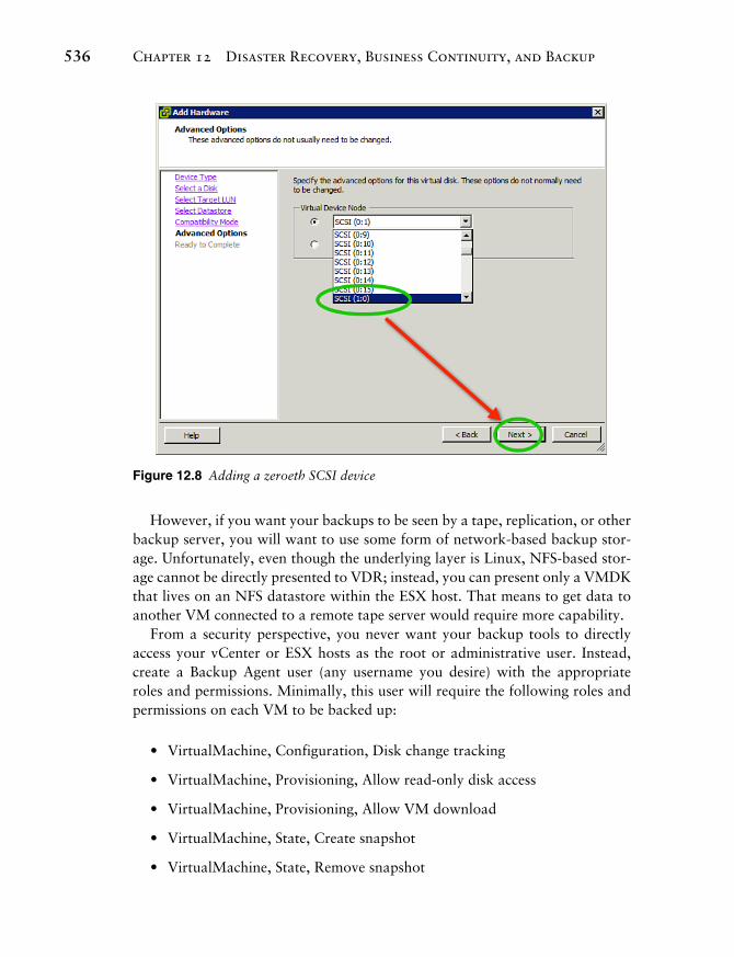
VDR not only backs up the VMs, it will deduplicate the backup before stor-ing it to a backup storage device. A backup storage device must be seen by the VDR appliance and can be implemented either via a network share, such as NFS or CIFS, or as a block-level device mounted via Raw Disk Map or VMDK. When planning your backup usage of VDR, you must realize that this is a VM and can see only the backup storage devices presented to it, not all the datastores on the host. The best solution is to use a RDM or network device and not to use a VMDK. How these devices are added to the VDR appliance is also critical; because of the way VDR performs hot-add of virtual disks it is required that any RDMs added to the appliance be added as the zeroeth device of a SCSI controller. In Figure 12.8 , we add a 500GB RDM to the VDR appliance and select the next available zeroeth (:0) device. This device can be used for data deduplication.
12_0137058977_ch12.indd 53512_0137058977_ch12.indd 535 1/18/11 9:09 AM1/18/11 9:09 AM
Chapter 12 Disaster Recovery, Business Continuity, and Backup536
Figure 12.8 Adding a zeroeth SCSI device
However, if you want your backups to be seen by a tape, replication, or other backup server, you will want to use some form of network-based backup stor-age. Unfortunately, even though the underlying layer is Linux, NFS-based stor-age cannot be directly presented to VDR; instead, you can present only a VMDK that lives on an NFS datastore within the ESX host. That means to get data to another VM connected to a remote tape server would require more capability.
From a security perspective, you never want your backup tools to directly access your vCenter or ESX hosts as the root or administrative user. Instead, create a Backup Agent user (any username you desire) with the appropriate roles and permissions. Minimally, this user will require the following roles and permissions on each VM to be backed up:
• VirtualMachine, Configuration, Disk change tracking
• VirtualMachine, Provisioning, Allow read-only disk access
• VirtualMachine, Provisioning, Allow VM download
• VirtualMachine, State, Create snapshot
• VirtualMachine, State, Remove snapshot
12_0137058977_ch12.indd 53612_0137058977_ch12.indd 536 1/18/11 9:09 AM1/18/11 9:09 AM
The Tools 537
Whereas on the VDR appliance, the following roles are required:
• Datastore, Allocate space
• VirtualMachine, Configuration, Add new disk
• VirtualMachine, Configuration, Change resource
• VirtualMachine, Configuration, Remove disk
• VirtualMachine, Configuration, Settings
Finally, the user needs read access to the Global License role so that it can check to see whether you are allowed to use VDR properly. In addition, these same privileges are generally needed by all backup tools.
Best Practice
When using VDR, ensure your protected folders contain, at most, 100 VMs.
Use a Backup Agent user instead of Administrator when accessing vCenter.
Use the next zeroeth (:0) SCSI device for all backup storage media added to the VDR appliance.
Use CIFS storage to allow backups to be seen by tape servers.
VDR is configured via the vSphere Client after the Data Recovery Client is installed and made available. To access the client after it is installed, go to the Homes, Solutions and Applications, VMware Data Recovery. The process to create a backup is as follows:
1. Connect vCenter to VDR .
2. Add a destination file share or disk to the appliance .
3. Create a backup job .
4. Schedule/run the backup job .
After the job is run, the backup could be copied to a tape server restored to a hot site or local VMFS in keeping with our backup paths discussed previously.
12_0137058977_ch12.indd 53712_0137058977_ch12.indd 537 1/18/11 9:09 AM1/18/11 9:09 AM
Chapter 12 Disaster Recovery, Business Continuity, and Backup538
Third-Party Tools
There are three major third-party tools for creating full disk backups and per-forming replication. Each of these works similarly to the VMware counterparts. To distinguish themselves they incorporate different approaches and functions. Veeam, Vizioncore, and PhD Virtual are the three main tools in this space with Symantec and HP Data Protector close seconds. For those with large legacy backup systems, Pancetera provides a tool to bridge the gap to the virtual environment.
Conclusion
It is imperative when using ESX that you create a DR and BC plan that results in successful backups and hot sites. The goal of this chapter was to present what is available to the users of ESX and the advanced capabilities of VMware clusters in terms of BC. Just be sure that a good DR and BC plan exists that covers all the possible disasters and that the plan is implemented and tested as often as necessary. Testing of backups and hot sites should be done as often as defined by your DR and BC policy.
12_0137058977_ch12.indd 53812_0137058977_ch12.indd 538 1/18/11 9:09 AM1/18/11 9:09 AM