disclaimer - stas.org.sg
TRANSCRIPT

DISCLAIMERThis guide may be used for reference purposes only. The contents of this guide are protected by copyright and other forms of proprietary rights owned by, licensed to or controlled by BCA and shall not be reproduced, republished, uploaded, posted, transmitted or otherwise distributed in any way, without the prior written permission of BCA. Modification of any of the contents or use of the contents for any other purpose will be a violation of BCA’s copyright and other intellectual property rights. Any reference herein to any specific commercial products, process, or service by trade name, trademark, manufacturer, or otherwise does not constitute or imply BCA’s endorsement or recommendation. BCA or any agency stated in this guide shall not be liable for any reliance on or misinterpretation of any information contained in this guide by any party.
All content used herein is for non-profit educational purposes. Where possible, all credit has been given to the respective owners or creators of the content.
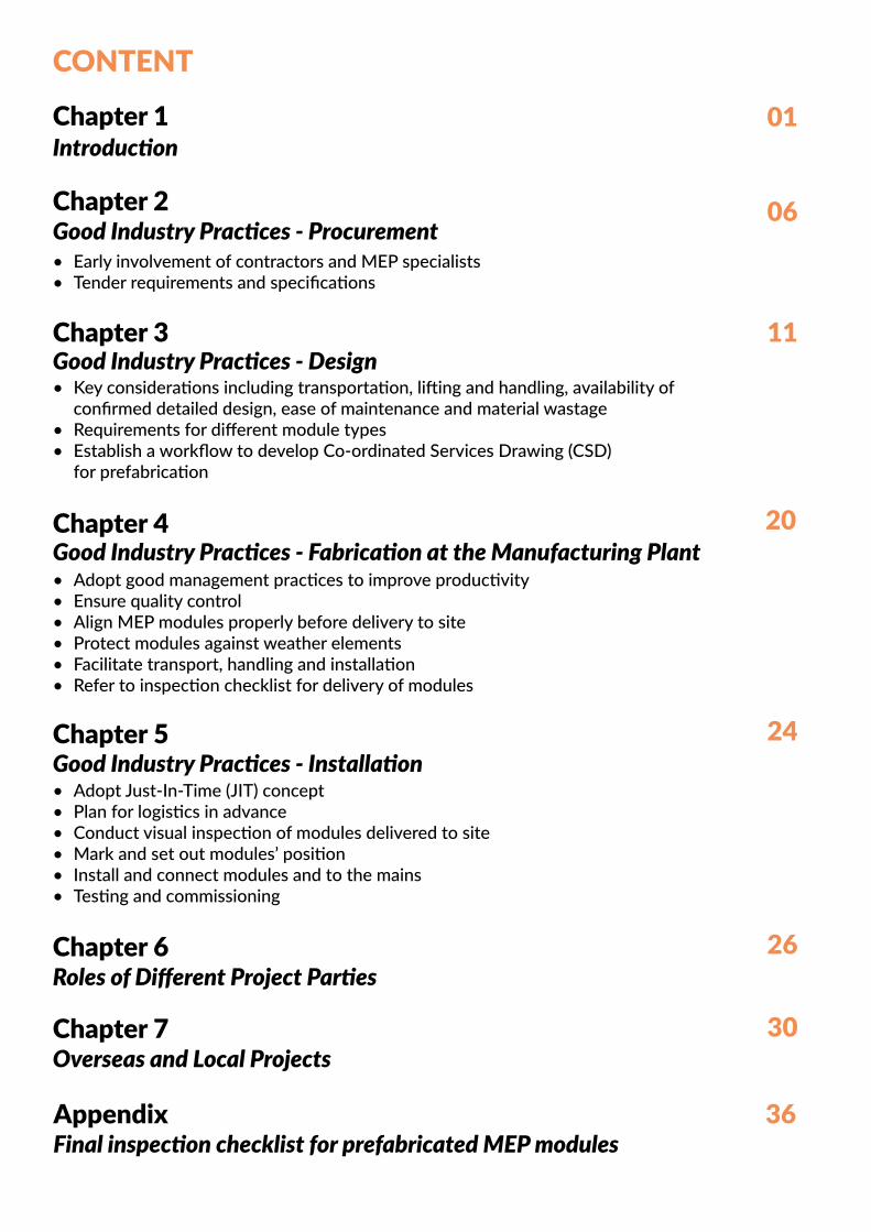
CONTENT
Chapter 1Introduction
Good Industry Practices - Procurement• Early involvement of contractors and MEP specialists• Tender requirements and specifications
Chapter 2
Good Industry Practices - DesignChapter 3
• Key considerations including transportation, lifting and handling, availability of confirmed detailed design, ease of maintenance and material wastage
• Requirements for different module types • Establish a workflow to develop Co-ordinated Services Drawing (CSD)
for prefabrication
Good Industry Practices - Fabrication at the Manufacturing PlantChapter 4
• Adopt good management practices to improve productivity• Ensure quality control• Align MEP modules properly before delivery to site• Protect modules against weather elements• Facilitate transport, handling and installation• Refer to inspection checklist for delivery of modules
Good Industry Practices - Installation Chapter 5
• Adopt Just-In-Time (JIT) concept• Plan for logistics in advance• Conduct visual inspection of modules delivered to site• Mark and set out modules’ position• Install and connect modules and to the mains• Testing and commissioning
Roles of Different Project Parties Chapter 6
Overseas and Local ProjectsChapter 7
Final inspection checklist for prefabricated MEP modulesAppendix
01
06
11
20
24
26
30
36
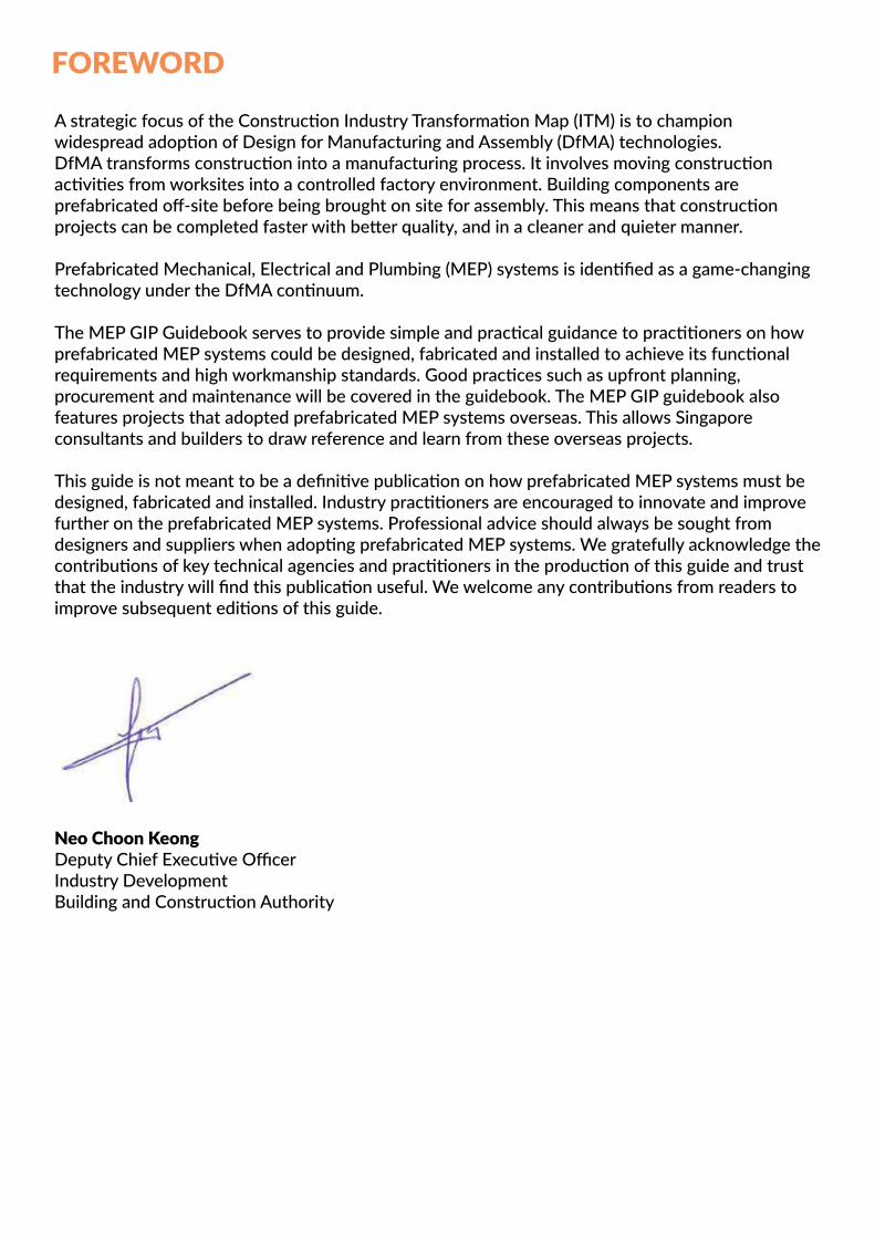
FOREWORD
A strategic focus of the Construction Industry Transformation Map (ITM) is to champion widespread adoption of Design for Manufacturing and Assembly (DfMA) technologies. DfMA transforms construction into a manufacturing process. It involves moving construction activities from worksites into a controlled factory environment. Building components are prefabricated off-site before being brought on site for assembly. This means that construction projects can be completed faster with better quality, and in a cleaner and quieter manner.
Prefabricated Mechanical, Electrical and Plumbing (MEP) systems is identified as a game-changing technology under the DfMA continuum.
The MEP GIP Guidebook serves to provide simple and practical guidance to practitioners on how prefabricated MEP systems could be designed, fabricated and installed to achieve its functional requirements and high workmanship standards. Good practices such as upfront planning, procurement and maintenance will be covered in the guidebook. The MEP GIP guidebook also features projects that adopted prefabricated MEP systems overseas. This allows Singapore consultants and builders to draw reference and learn from these overseas projects.
This guide is not meant to be a definitive publication on how prefabricated MEP systems must be designed, fabricated and installed. Industry practitioners are encouraged to innovate and improve further on the prefabricated MEP systems. Professional advice should always be sought from designers and suppliers when adopting prefabricated MEP systems. We gratefully acknowledge the contributions of key technical agencies and practitioners in the production of this guide and trust that the industry will find this publication useful. We welcome any contributions from readers to improve subsequent editions of this guide.
Neo Choon KeongDeputy Chief Executive OfficerIndustry DevelopmentBuilding and Construction Authority
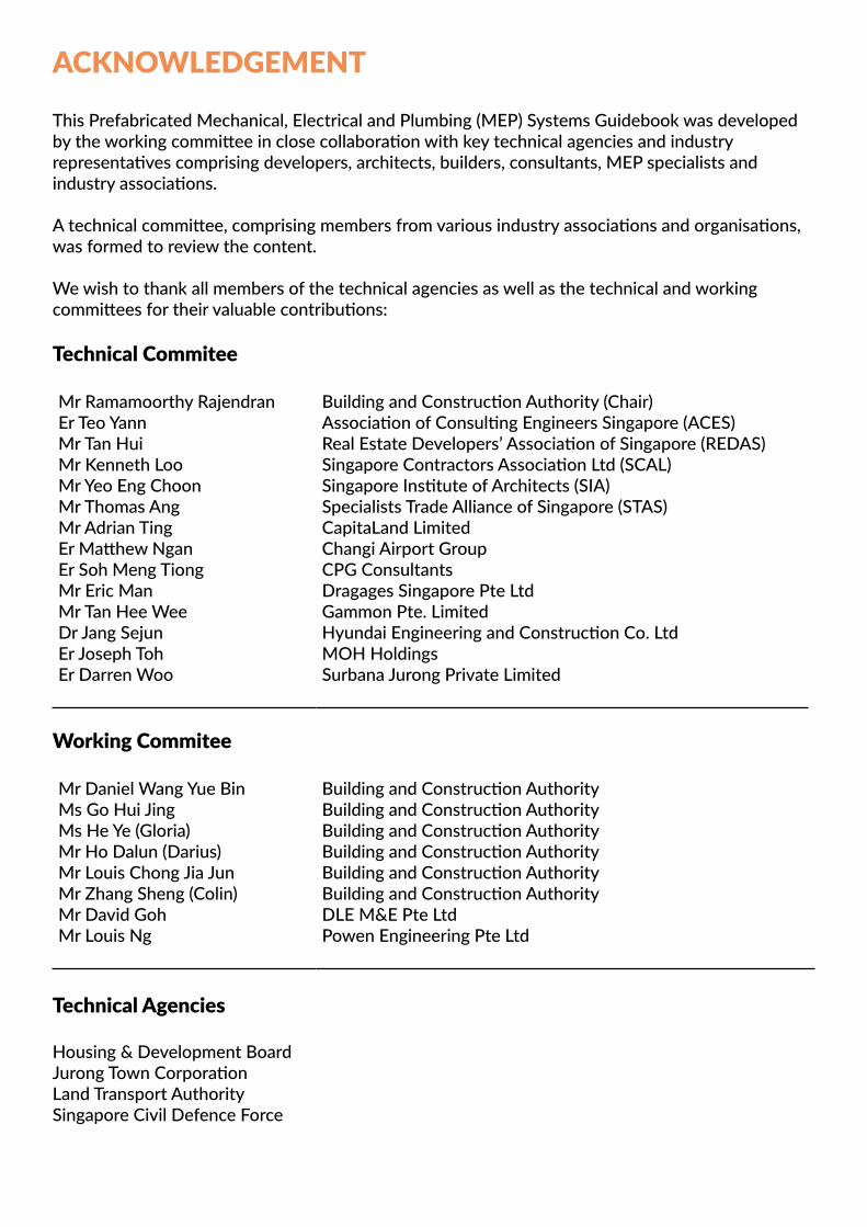
ACKNOWLEDGEMENT
This Prefabricated Mechanical, Electrical and Plumbing (MEP) Systems Guidebook was developed by the working committee in close collaboration with key technical agencies and industry representatives comprising developers, architects, builders, consultants, MEP specialists and industry associations.
A technical committee, comprising members from various industry associations and organisations, was formed to review the content.
We wish to thank all members of the technical agencies as well as the technical and working committees for their valuable contributions:
Technical Commitee
Mr Ramamoorthy RajendranEr Teo YannMr Tan HuiMr Kenneth LooMr Yeo Eng ChoonMr Thomas AngMr Adrian TingEr Matthew NganEr Soh Meng TiongMr Eric ManMr Tan Hee WeeDr Jang SejunEr Joseph TohEr Darren Woo
Building and Construction Authority (Chair)Association of Consulting Engineers Singapore (ACES)Real Estate Developers’ Association of Singapore (REDAS)Singapore Contractors Association Ltd (SCAL)Singapore Institute of Architects (SIA)Specialists Trade Alliance of Singapore (STAS)CapitaLand LimitedChangi Airport GroupCPG ConsultantsDragages Singapore Pte LtdGammon Pte. LimitedHyundai Engineering and Construction Co. LtdMOH HoldingsSurbana Jurong Private Limited
Working Commitee
Mr Daniel Wang Yue BinMs Go Hui JingMs He Ye (Gloria)Mr Ho Dalun (Darius) Mr Louis Chong Jia JunMr Zhang Sheng (Colin)Mr David GohMr Louis Ng
Building and Construction AuthorityBuilding and Construction AuthorityBuilding and Construction AuthorityBuilding and Construction AuthorityBuilding and Construction AuthorityBuilding and Construction AuthorityDLE M&E Pte LtdPowen Engineering Pte Ltd
Technical Agencies
Housing & Development BoardJurong Town CorporationLand Transport AuthoritySingapore Civil Defence Force
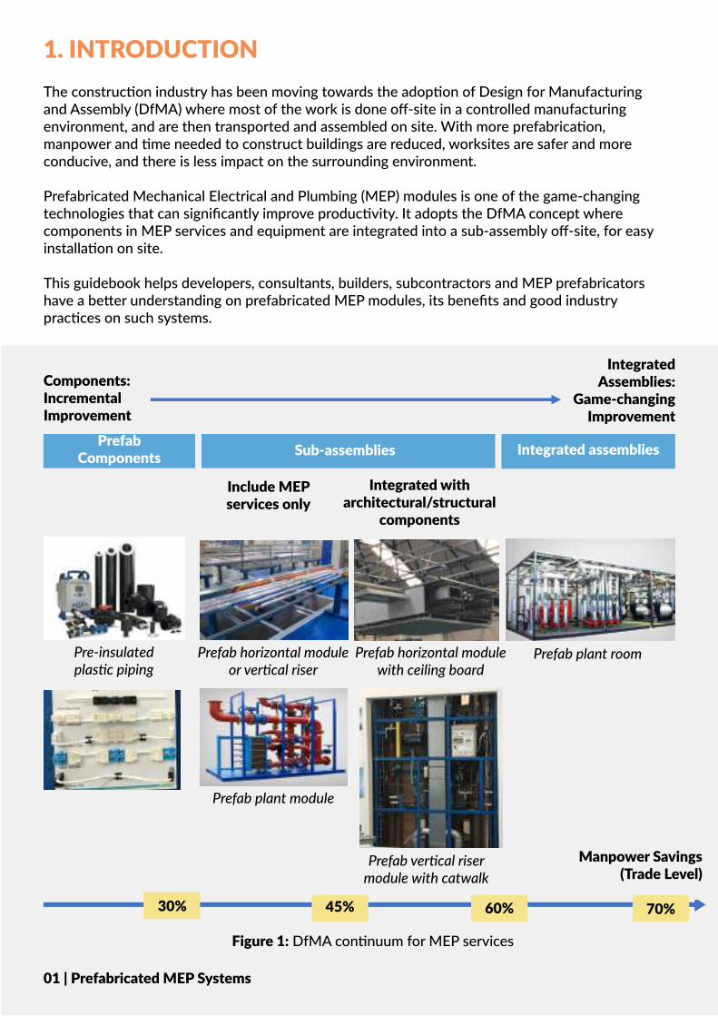
1. INTRODUCTIONThe construction industry has been moving towards the adoption of Design for Manufacturing and Assembly (DfMA) where most of the work is done off-site in a controlled manufacturing environment, and are then transported and assembled on site. With more prefabrication, manpower and time needed to construct buildings are reduced, worksites are safer and more conducive, and there is less impact on the surrounding environment.
Prefabricated Mechanical Electrical and Plumbing (MEP) modules is one of the game-changing technologies that can significantly improve productivity. It adopts the DfMA concept where components in MEP services and equipment are integrated into a sub-assembly off-site, for easy installation on site.
This guidebook helps developers, consultants, builders, subcontractors and MEP prefabricators have a better understanding on prefabricated MEP modules, its benefits and good industry practices on such systems.
Prefab Components Sub-assemblies Integrated assemblies
Components:Incremental Improvement
Integrated Assemblies:
Game-changing Improvement
Include MEP services only
Integrated with architectural/structural
components
Pre-insulated plastic piping
Prefab horizontal module with ceiling board
Prefab horizontal moduleor vertical riser
Prefab plant module
Prefab plant room
Prefab vertical riser module with catwalk
Figure 1: DfMA continuum for MEP services
30% 45% 60% 70%
01 | Prefabricated MEP Systems
Manpower Savings (Trade Level)
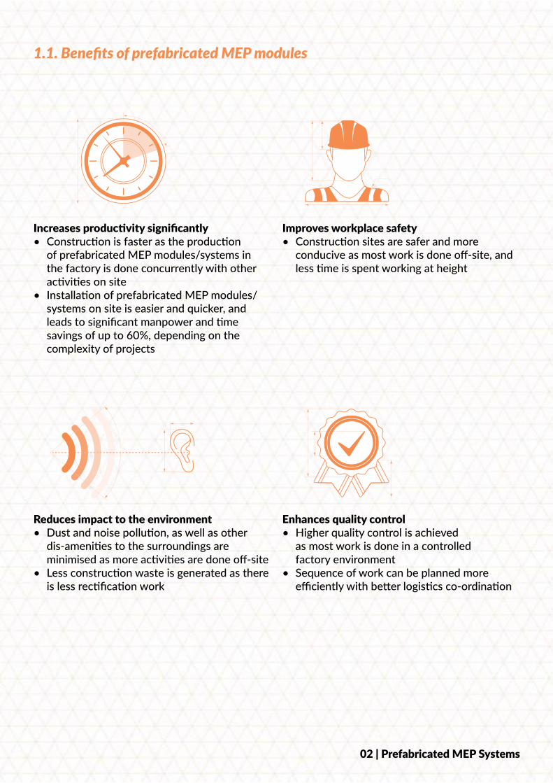
Increases productivity significantly • Construction is faster as the production
of prefabricated MEP modules/systems in the factory is done concurrently with other activities on site
• Installation of prefabricated MEP modules/systems on site is easier and quicker, and leads to significant manpower and time savings of up to 60%, depending on the complexity of projects
Improves workplace safety • Construction sites are safer and more
conducive as most work is done off-site, and less time is spent working at height
Reduces impact to the environment • Dust and noise pollution, as well as other
dis-amenities to the surroundings are minimised as more activities are done off-site
• Less construction waste is generated as there is less rectification work
Enhances quality control• Higher quality control is achieved
as most work is done in a controlled factory environment
• Sequence of work can be planned more efficiently with better logistics co-ordination
1.1. Benefits of prefabricated MEP modules
02 | Prefabricated MEP Systems
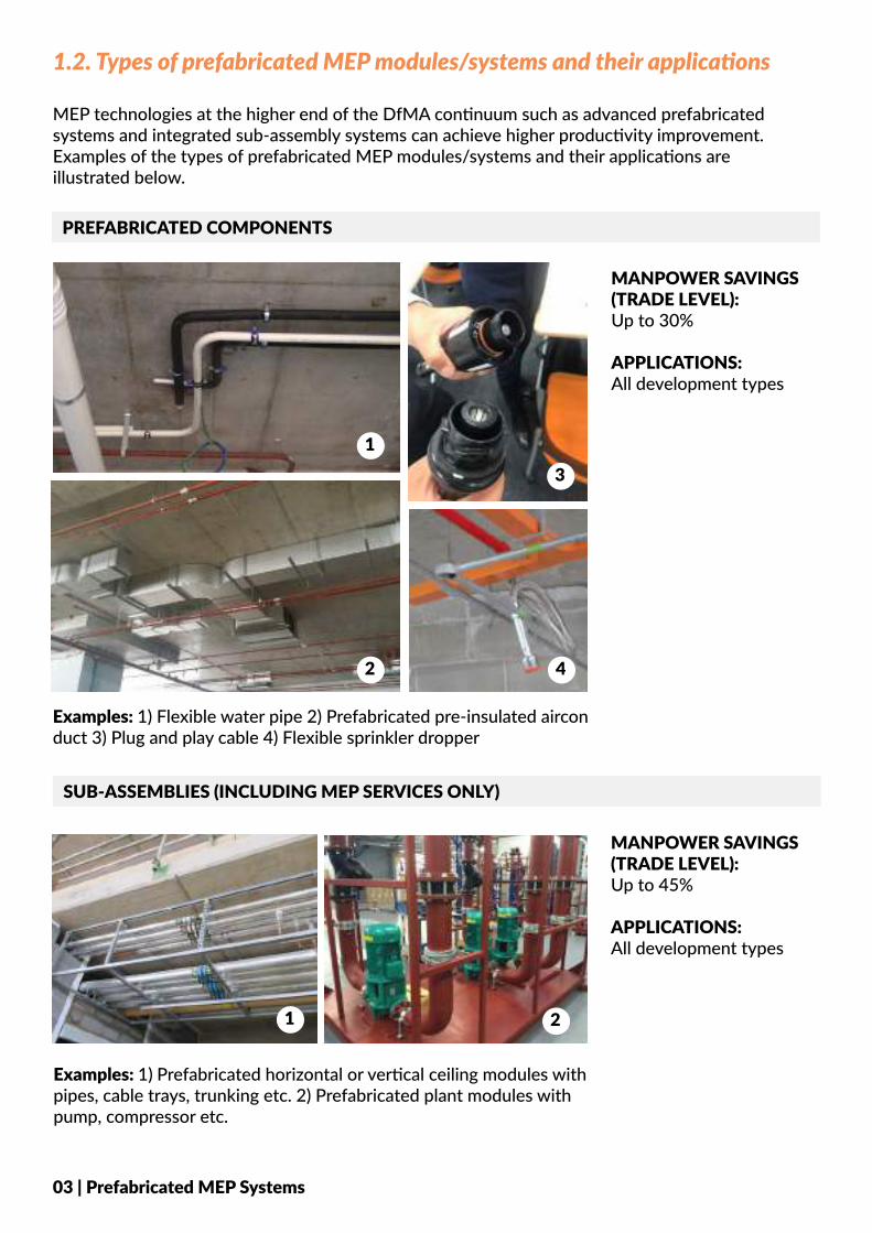
1.2. Types of prefabricated MEP modules/systems and their applications
MEP technologies at the higher end of the DfMA continuum such as advanced prefabricated systems and integrated sub-assembly systems can achieve higher productivity improvement. Examples of the types of prefabricated MEP modules/systems and their applications are illustrated below.
PREFABRICATED COMPONENTS
Examples: 1) Flexible water pipe 2) Prefabricated pre-insulated aircon duct 3) Plug and play cable 4) Flexible sprinkler dropper
MANPOWER SAVINGS (TRADE LEVEL):Up to 30%
APPLICATIONS: All development types
SUB-ASSEMBLIES (INCLUDING MEP SERVICES ONLY)
MANPOWER SAVINGS (TRADE LEVEL):Up to 45%
APPLICATIONS: All development types
Examples: 1) Prefabricated horizontal or vertical ceiling modules with pipes, cable trays, trunking etc. 2) Prefabricated plant modules with pump, compressor etc.
1
2
3
4
1 2
03 | Prefabricated MEP Systems
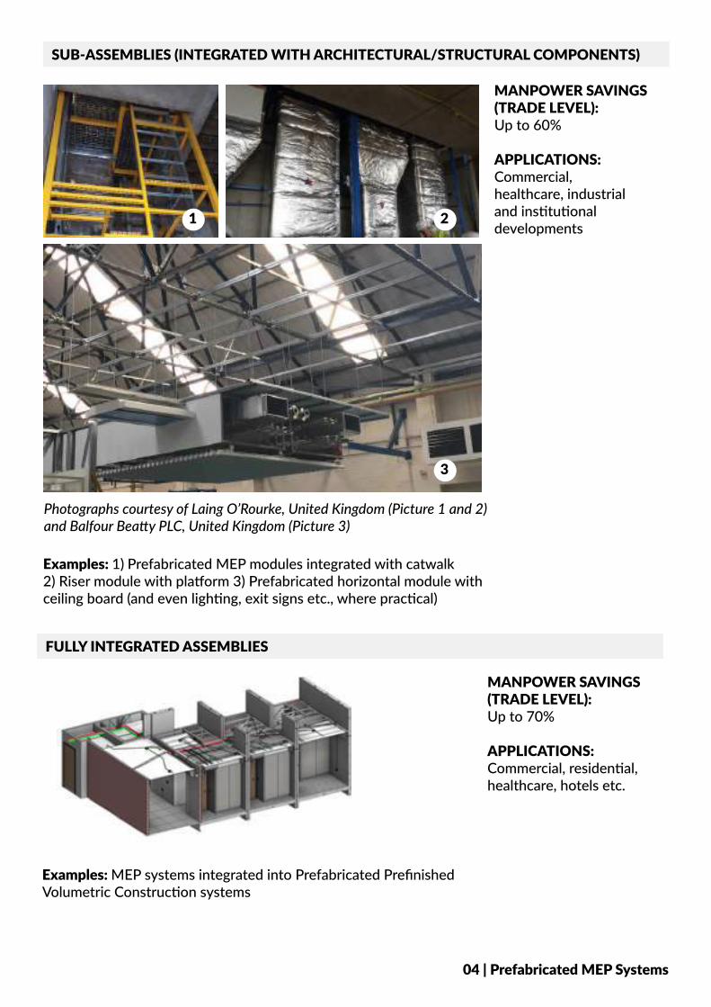
SUB-ASSEMBLIES (INTEGRATED WITH ARCHITECTURAL/STRUCTURAL COMPONENTS)
MANPOWER SAVINGS (TRADE LEVEL):Up to 60%
APPLICATIONS: Commercial, healthcare, industrial and institutional developments
Examples: 1) Prefabricated MEP modules integrated with catwalk2) Riser module with platform 3) Prefabricated horizontal module with ceiling board (and even lighting, exit signs etc., where practical)
FULLY INTEGRATED ASSEMBLIES
Examples: MEP systems integrated into Prefabricated Prefinished Volumetric Construction systems
MANPOWER SAVINGS (TRADE LEVEL):Up to 70%
APPLICATIONS: Commercial, residential, healthcare, hotels etc.
1 2
3
04 | Prefabricated MEP Systems
Photographs courtesy of Laing O’Rourke, United Kingdom (Picture 1 and 2) and Balfour Beatty PLC, United Kingdom (Picture 3)
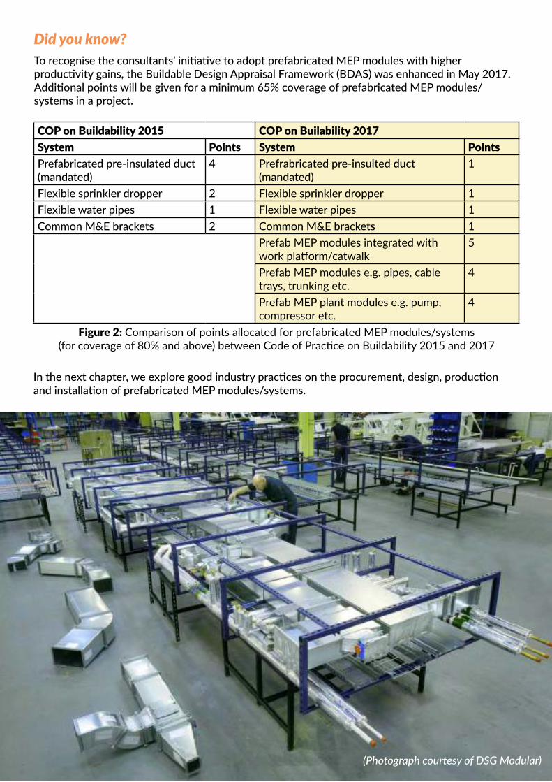
To recognise the consultants’ initiative to adopt prefabricated MEP modules with higher productivity gains, the Buildable Design Appraisal Framework (BDAS) was enhanced in May 2017. Additional points will be given for a minimum 65% coverage of prefabricated MEP modules/systems in a project.
COP on Buildability 2015 COP on Builability 2017System Points System PointsPrefabricated pre-insulated duct (mandated)
4 Prefrabricated pre-insulted duct (mandated)
1
Flexible sprinkler dropper 2 Flexible sprinkler dropper 1Flexible water pipes 1 Flexible water pipes 1Common M&E brackets 2 Common M&E brackets 1
Prefab MEP modules integrated with work platform/catwalk
5
Prefab MEP modules e.g. pipes, cable trays, trunking etc.
4
Prefab MEP plant modules e.g. pump, compressor etc.
4
Figure 2: Comparison of points allocated for prefabricated MEP modules/systems (for coverage of 80% and above) between Code of Practice on Buildability 2015 and 2017
In the next chapter, we explore good industry practices on the procurement, design, production and installation of prefabricated MEP modules/systems.
(Photograph courtesy of DSG Modular)
Did you know?
COP on Buildability 2015 COP on Builability 2017System Points System PointsPrefabricated pre-insulated duct (mandated)
4 Prefrabricated pre-insulted duct (mandated)
1
Flexible sprinkler dropper 2 Flexible sprinkler dropper 1Flexible water pipes 1 Flexible water pipes 1Common M&E brackets 2 Common M&E brackets 1
Prefab MEP modules integrated with work platform/catwalk
5
Prefab MEP modules e.g. pipes, cable trays, trunking etc.
4
Prefab MEP plant modules e.g. pump, compressor etc.
4
2.1. Early involvement of contractors and MEP specialists
2. GOOD INDUSTRY PRACTICES - PROCUREMENT
It is important to engage the MEP specialists and main contractor early upfront during the design stage of the project. By incorporating their inputs into the design, a more effective technical solution can be achieved. Design clashes and structural safety concerns due to co-ordination issues can be eliminated. The design of MEP systems will also be more holistic and take into consideration the ease and accessibility of maintenance, replacement and upgrading of such systems.
The Design and Build (D&B) and Design Development and Build (DDB) procurement models facilitate early involvement of the main contractor and MEP specialists during the design stage. This significantly improves the buildability and constructability of the prefabricated MEP design, leading to higher construction productivity.
Design and Build (D&B) modelD&B is a procurement method where the functions of design and construction are placed entirely with the main contractor. Based on the design brief provided by the client, the main contractor will engage his own consultants and the MEP specialists to fully design, develop and construct the development, including the design and installation of prefabricated MEP systems.
Design Development and Build (DDB) modelThe DDB model is similar to the D&B model, except that the client will engage his own consultants to develop the conceptual design first. Based on this design concept, the main contractor will work with his own consultants and the MEP specialists to develop the full design and construct the development, including designing and installing the prefabricated MEP systems.
Besides the above procurement models, the consultants, main contractor and MEP specialists can also team up to submit their design to tender for projects.
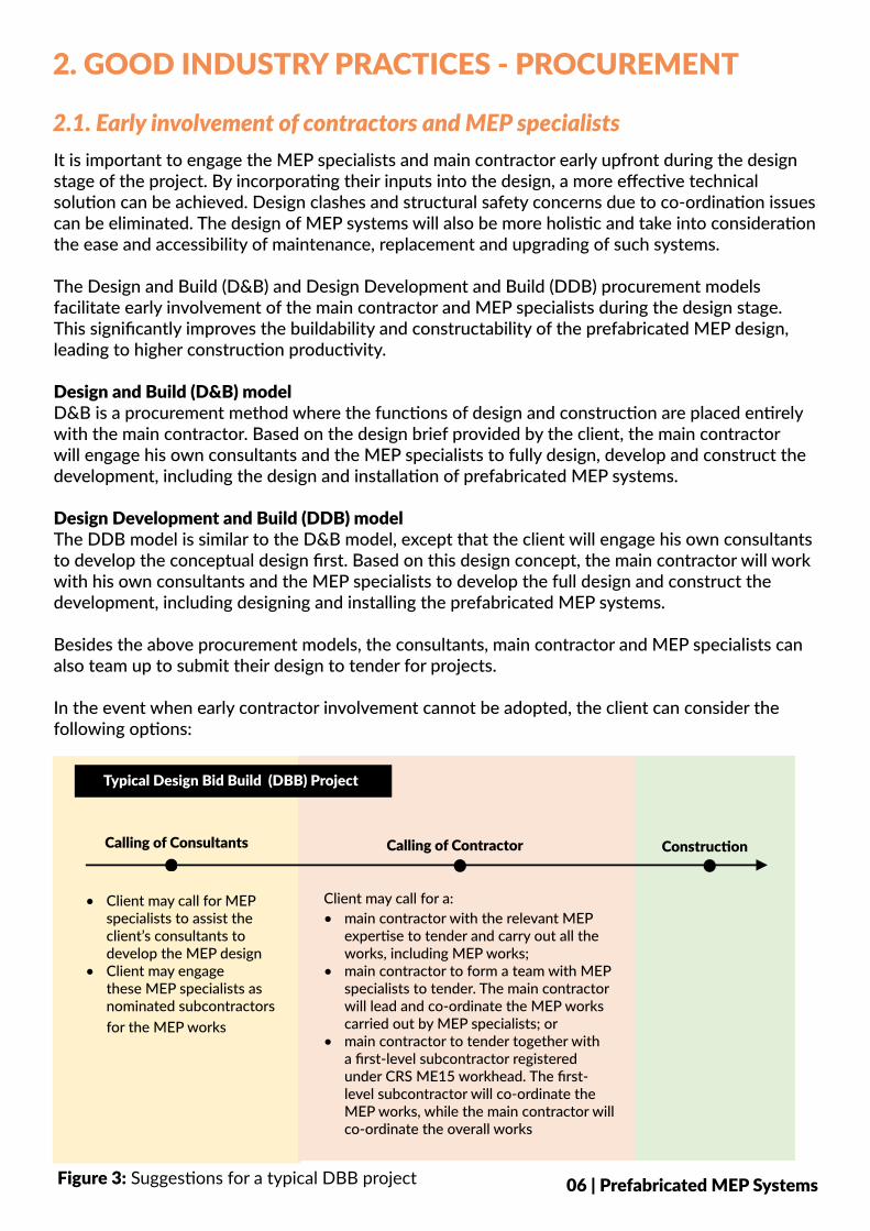
In the event when early contractor involvement cannot be adopted, the client can consider the following options:
06 | Prefabricated MEP Systems
• Client may call for MEP specialists to assist the client’s consultants to develop the MEP design
• Client may engage these MEP specialists as nominated subcontractors for the MEP works
• main contractor with the relevant MEP expertise to tender and carry out all the works, including MEP works;
• main contractor to form a team with MEP specialists to tender. The main contractor will lead and co-ordinate the MEP works carried out by MEP specialists; or
• main contractor to tender together with a first-level subcontractor registered under CRS ME15 workhead. The first-level subcontractor will co-ordinate the MEP works, while the main contractor will co-ordinate the overall works
Client may call for a:
Calling of Consultants Calling of Contractor Construction
Typical Design Bid Build (DBB) Project
Figure 3: Suggestions for a typical DBB project
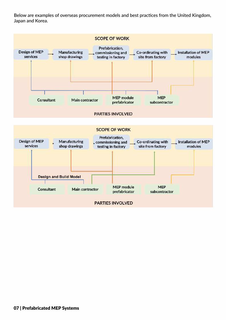
Below are examples of overseas procurement models and best practices from the United Kingdom, Japan and Korea.
07 | Prefabricated MEP Systems
2.2. Tender requirements and specifications
The requirement to adopt prefabricated MEP modules cannot be an afterthought and needs to be incorporated upfront in the tender documents, starting from the project brief. The early decision to adopt MEP modules in the project allows greater continuity of design and maximises productivity gains.
Project milestones are different when prefabricated MEP modules are adopted in a project. As such, the contract provisions of a project adopting prefabricated MEP modules should take into account the following considerations:
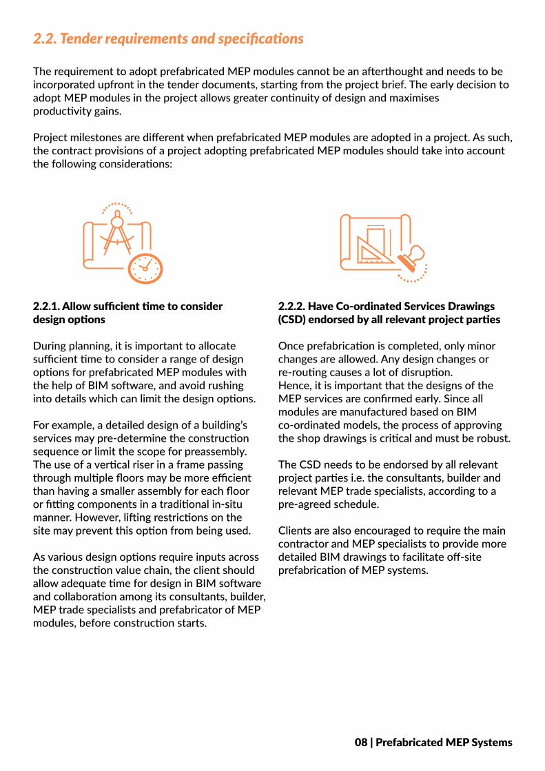
2.2.1. Allow sufficient time to consider design options
During planning, it is important to allocate sufficient time to consider a range of design options for prefabricated MEP modules with the help of BIM software, and avoid rushing into details which can limit the design options.
For example, a detailed design of a building’s services may pre-determine the construction sequence or limit the scope for preassembly. The use of a vertical riser in a frame passing through multiple floors may be more efficient than having a smaller assembly for each floor or fitting components in a traditional in-situ manner. However, lifting restrictions on the site may prevent this option from being used.
As various design options require inputs across the construction value chain, the client should allow adequate time for design in BIM software and collaboration among its consultants, builder, MEP trade specialists and prefabricator of MEP modules, before construction starts.
2.2.2. Have Co-ordinated Services Drawings (CSD) endorsed by all relevant project parties
Once prefabrication is completed, only minor changes are allowed. Any design changes or re-routing causes a lot of disruption. Hence, it is important that the designs of the MEP services are confirmed early. Since all modules are manufactured based on BIM co-ordinated models, the process of approving the shop drawings is critical and must be robust.
The CSD needs to be endorsed by all relevant project parties i.e. the consultants, builder and relevant MEP trade specialists, according to a pre-agreed schedule.
Clients are also encouraged to require the main contractor and MEP specialists to provide more detailed BIM drawings to facilitate off-site prefabrication of MEP systems.
08 | Prefabricated MEP Systems
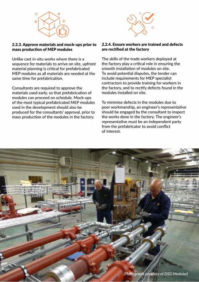
2.2.3. Approve materials and mock-ups prior to mass production of MEP modules
Unlike cast in-situ works where there is a sequence for materials to arrive on site, upfront material planning is critical for prefabricated MEP modules as all materials are needed at the same time for prefabrication.
Consultants are required to approve the materials used early, so that prefabrication of modules can proceed on schedule. Mock-ups of the most typical prefabricated MEP modules used in the development should also be produced for the consultants’ approval, prior to mass production of the modules in the factory.
09 | Prefabricated MEP Systems
2.2.4. Ensure workers are trained and defects are rectified at the factory
The skills of the trade workers deployed at the factory play a critical role in ensuring the smooth installation of modules on site. To avoid potential disputes, the tender can include requirements for MEP specialist contractors to provide training for workers in the factory, and to rectify defects found in the modules installed on site.
To minimise defects in the modules due to poor workmanship, an engineer’s representative should be engaged by the consultant to inspect the works done in the factory. The engineer’s representative must be an independent party from the prefabricator to avoid conflict of interest.
(Photograph courtesy of DSG Modular)
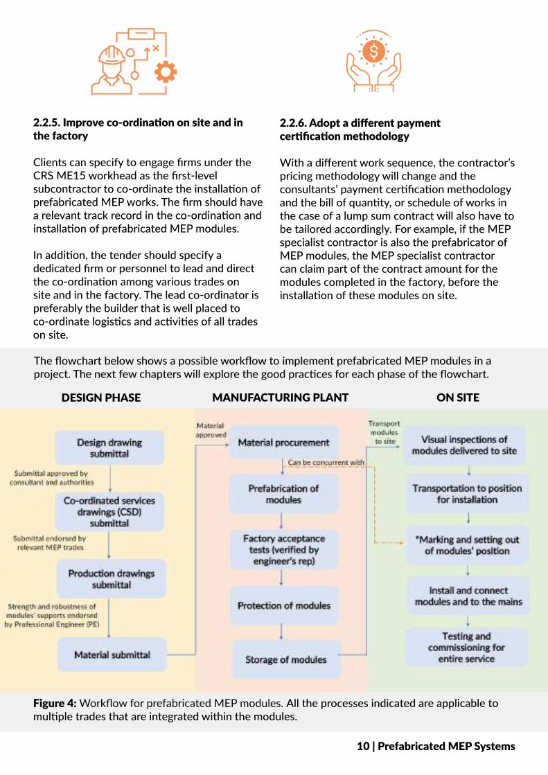
The flowchart below shows a possible workflow to implement prefabricated MEP modules in a project. The next few chapters will explore the good practices for each phase of the flowchart.
Figure 4: Workflow for prefabricated MEP modules. All the processes indicated are applicable to multiple trades that are integrated within the modules.
DESIGN PHASE MANUFACTURING PLANT ON SITE
10 | Prefabricated MEP Systems
2.2.5. Improve co-ordination on site and in the factory
Clients can specify to engage firms under the CRS ME15 workhead as the first-level subcontractor to co-ordinate the installation of prefabricated MEP works. The firm should have a relevant track record in the co-ordination and installation of prefabricated MEP modules.
In addition, the tender should specify a dedicated firm or personnel to lead and direct the co-ordination among various trades on site and in the factory. The lead co-ordinator is preferably the builder that is well placed to co-ordinate logistics and activities of all trades on site.
2.2.6. Adopt a different payment certification methodology
With a different work sequence, the contractor’s pricing methodology will change and the consultants’ payment certification methodology and the bill of quantity, or schedule of works in the case of a lump sum contract will also have to be tailored accordingly. For example, if the MEP specialist contractor is also the prefabricator of MEP modules, the MEP specialist contractor can claim part of the contract amount for the modules completed in the factory, before the installation of these modules on site.
3. GOOD INDUSTRY PRACTICES - DESIGN
3.1. Key considerations3.1.1. TransportationThe length of each module is subject to the project requirements and standard sizes of materials supplied. In overseas projects, the typical length of each module is either 6 metres or 12 metres because pipes are supplied in these lengths.
Should the MEP modules fall outside the below parameters, police escorts are required under LTA’s traffic regulatory requirements. • Height: < 4.5 metres (inclusive of truck height)• Width: < 3.4 metres • Weight: < 80 tons
*Subject to prevailing requirements by LTA.
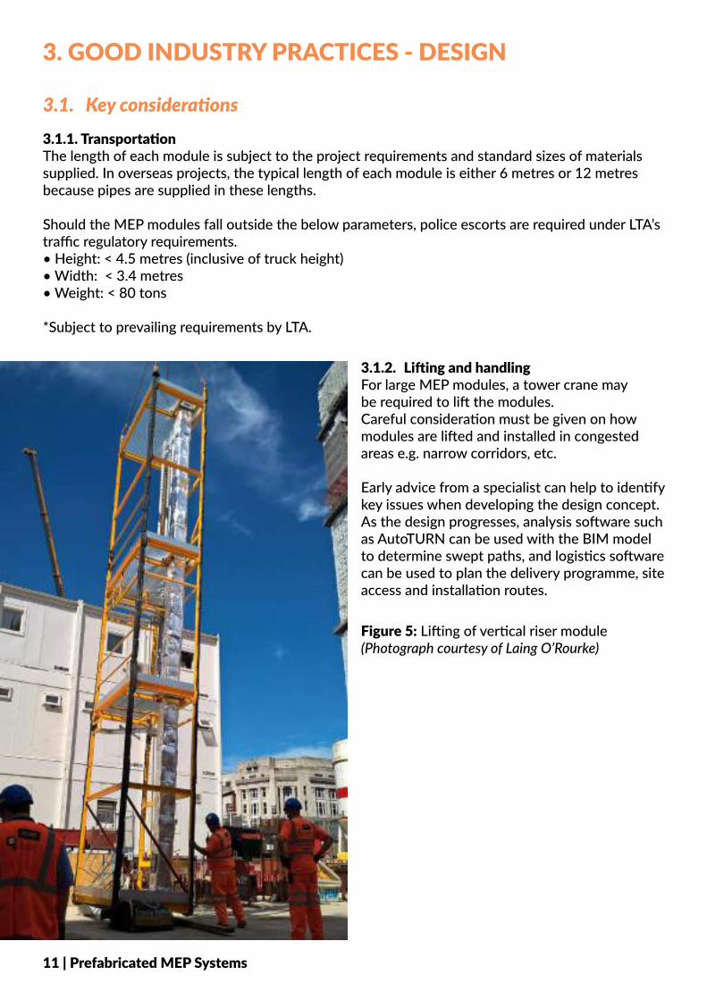
3.1.2. Lifting and handlingFor large MEP modules, a tower crane may be required to lift the modules. Careful consideration must be given on how modules are lifted and installed in congested areas e.g. narrow corridors, etc.
Early advice from a specialist can help to identify key issues when developing the design concept. As the design progresses, analysis software such as AutoTURN can be used with the BIM model to determine swept paths, and logistics software can be used to plan the delivery programme, site access and installation routes.
Figure 5: Lifting of vertical riser module (Photograph courtesy of Laing O’Rourke)
11 | Prefabricated MEP Systems
3.1.3. Availability of confirmed detailed designIn some zones, design changes or missing details might be inevitable, such as the retail space of a commercial project which is subjected to changes in tenancy. Consultants can identify these zones from the outset. The designers of MEP modules will then be able to include additional provisions during the design stage, to prevent reworks downstream.
For example, if the function of a particular zone cannot be confirmed before fabrication of modules commences, the horizontal ceiling module in the typical corridor should allow space for potential additional services to be installed on site at a later stage.
3.1.4. Ease of maintenanceThe design of prefabricated MEP modules should consider the entire building lifecycle, including downstream maintenance. Maintainability of MEP systems should be considered during the design stage.
Inputs from the facilities management team on the orientation of valves, accessibility and future addition and alteration requirements should be incorporated in the design as early as possible. For example, valves should be placed in a common fixed location to ensure all modules are accessible. Consultants should also provide clear access routes to the modules in the design, for example by allowing access space between the main services route and partition walls for installation of services into the rooms adjacent to the corridor.
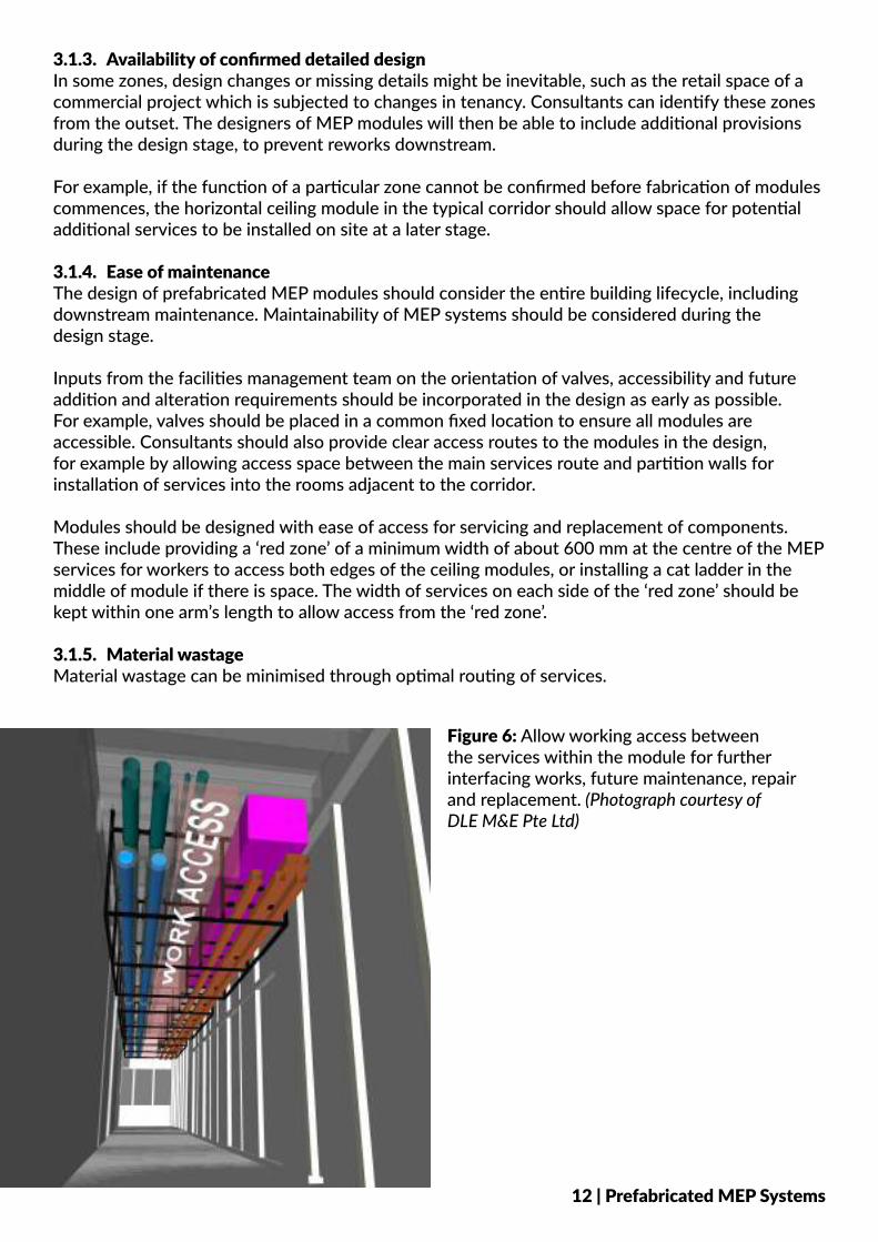
Modules should be designed with ease of access for servicing and replacement of components. These include providing a ‘red zone’ of a minimum width of about 600 mm at the centre of the MEP services for workers to access both edges of the ceiling modules, or installing a cat ladder in the middle of module if there is space. The width of services on each side of the ‘red zone’ should be kept within one arm’s length to allow access from the ‘red zone’.
3.1.5. Material wastageMaterial wastage can be minimised through optimal routing of services.
Figure 6: Allow working access between the services within the module for further interfacing works, future maintenance, repair and replacement. (Photograph courtesy of DLE M&E Pte Ltd)
12 | Prefabricated MEP Systems
ACCESS
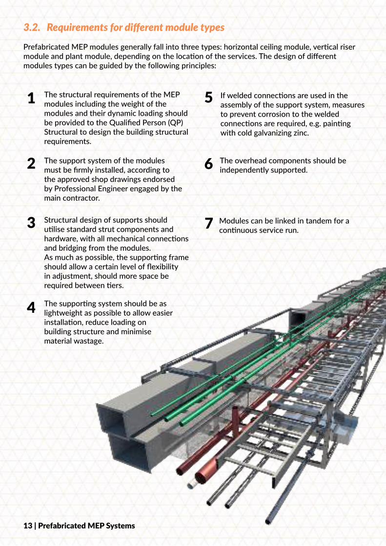
3.2. Requirements for different module types
Prefabricated MEP modules generally fall into three types: horizontal ceiling module, vertical riser module and plant module, depending on the location of the services. The design of different modules types can be guided by the following principles:
1 The structural requirements of the MEP modules including the weight of the modules and their dynamic loading should be provided to the Qualified Person (QP) Structural to design the building structural requirements.
The support system of the modules must be firmly installed, according to the approved shop drawings endorsed by Professional Engineer engaged by the main contractor.
Structural design of supports should utilise standard strut components and hardware, with all mechanical connections and bridging from the modules. As much as possible, the supporting frame should allow a certain level of flexibility in adjustment, should more space be required between tiers.
The supporting system should be as lightweight as possible to allow easier installation, reduce loading on building structure and minimise material wastage.
If welded connections are used in the assembly of the support system, measures to prevent corrosion to the welded connections are required, e.g. painting with cold galvanizing zinc.
The overhead components should be independently supported.
Modules can be linked in tandem for a continuous service run.
13 | Prefabricated MEP Systems
2
3
4
5
6
7
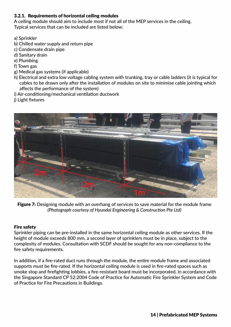
3.2.1. Requirements of horizontal ceiling modules A ceiling module should aim to include most if not all of the MEP services in the ceiling. Typical services that can be included are listed below:
a) Sprinkler b) Chilled water supply and return pipec) Condensate drain piped) Sanitary draine) Plumbingf) Town gasg) Medical gas systems (if applicable)h) Electrical and extra low voltage cabling system with trunking, tray or cable ladders (it is typical for
cables to be drawn only after the installation of modules on site to minimise cable jointing which affects the performance of the system)
i) Air-conditioning/mechanical ventilation ductworkj) Light fixtures
Figure 7: Designing module with an overhang of services to save material for the module frame(Photograph courtesy of Hyundai Engineering & Construction Pte Ltd)
Fire safety Sprinkler piping can be pre-installed in the same horizontal ceiling module as other services. If the height of module exceeds 800 mm, a second layer of sprinklers must be in place, subject to the complexity of modules. Consultation with SCDF should be sought for any non-compliance to the fire safety requirements.
In addition, if a fire-rated duct runs through the module, the entire module frame and associated supports must be fire-rated. If the horizontal ceiling module is used in fire-rated spaces such as smoke stop and firefighting lobbies, a fire-resistant board must be incorporated, in accordance with the Singapore Standard CP 52:2004 Code of Practice for Automatic Fire Sprinkler System and Code of Practice for Fire Precautions in Buildings.
14 | Prefabricated MEP Systems
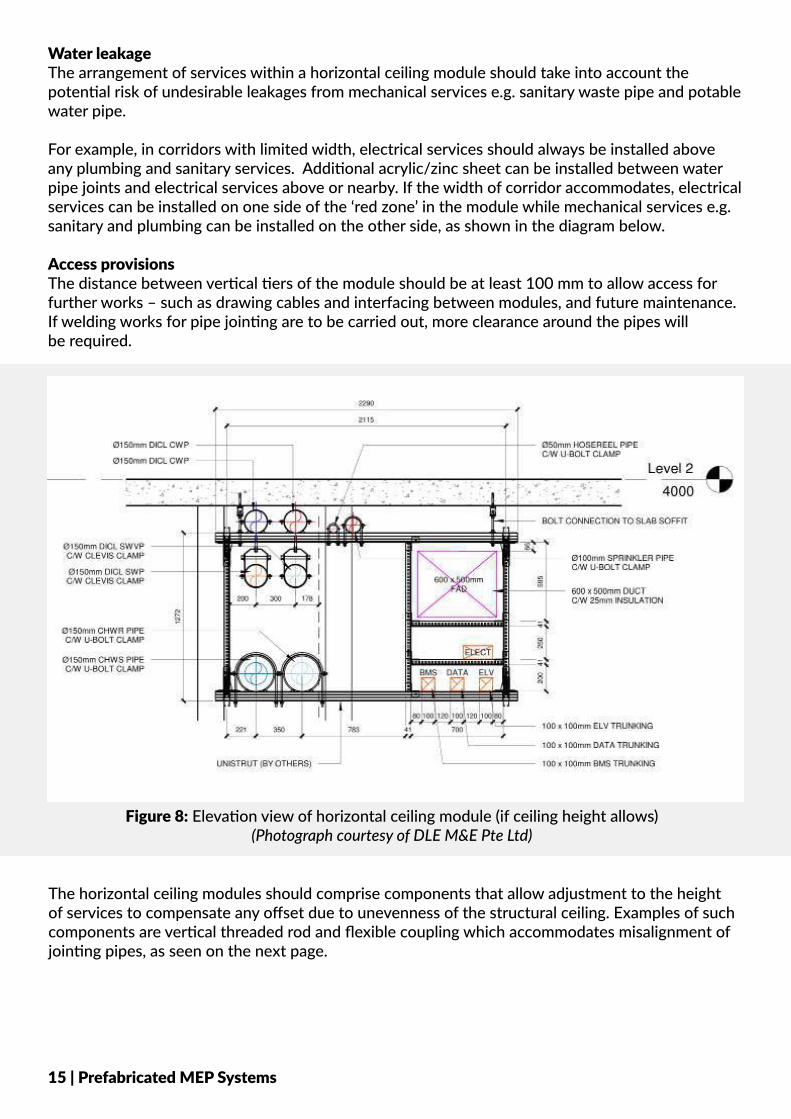
Water leakage The arrangement of services within a horizontal ceiling module should take into account the potential risk of undesirable leakages from mechanical services e.g. sanitary waste pipe and potable water pipe.
For example, in corridors with limited width, electrical services should always be installed above any plumbing and sanitary services. Additional acrylic/zinc sheet can be installed between water pipe joints and electrical services above or nearby. If the width of corridor accommodates, electrical services can be installed on one side of the ‘red zone’ in the module while mechanical services e.g. sanitary and plumbing can be installed on the other side, as shown in the diagram below.
Access provisionsThe distance between vertical tiers of the module should be at least 100 mm to allow access for further works – such as drawing cables and interfacing between modules, and future maintenance. If welding works for pipe jointing are to be carried out, more clearance around the pipes will be required.
Figure 8: Elevation view of horizontal ceiling module (if ceiling height allows) (Photograph courtesy of DLE M&E Pte Ltd)
The horizontal ceiling modules should comprise components that allow adjustment to the height of services to compensate any offset due to unevenness of the structural ceiling. Examples of such components are vertical threaded rod and flexible coupling which accommodates misalignment of jointing pipes, as seen on the next page.
15 | Prefabricated MEP Systems
3.2.2. Requirements of vertical riser modules A riser module comprises vertical riser ducts and pipes. The vertical services in each riser module can be installed horizontally at ground level in the factory, and branch out to multiple floors.
A riser module can be installed prior to, and independently of, the erection of block walls of the riser shaft. Another method of installation is to lower the riser modules into the riser shaft through designated openings in the top floor. Therefore, lifting lugs and bracketry should be incorporated in the design of vertical riser modules.
Figure 10 (right): Vertical riser module placed in position (Photograph courtesy of Balfour Beatty PLC)
16 | Prefabricated MEP Systems
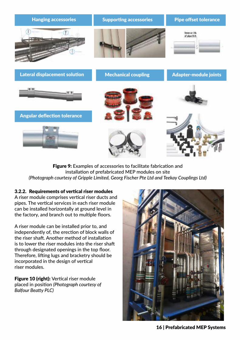
Figure 9: Examples of accessories to facilitate fabrication and installation of prefabricated MEP modules on site
(Photograph courtesy of Gripple Limited, Georg Fischer Pte Ltd and Teekay Couplings Ltd)
Hanging accessories Supporting accessories
Mechanical couplingLateral displacement solution
Angular deflection tolerance
Adapter-module joints
Pipe offset tolerance
3.2.3. Requirements of plant modules
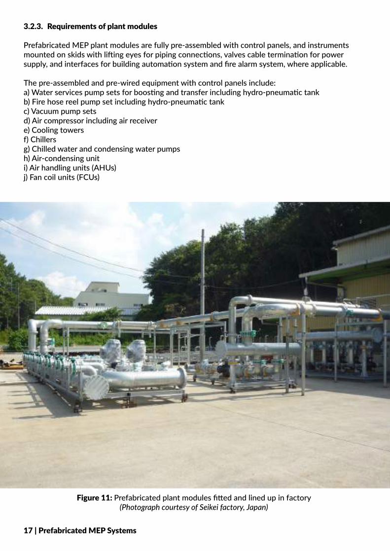
Prefabricated MEP plant modules are fully pre-assembled with control panels, and instruments mounted on skids with lifting eyes for piping connections, valves cable termination for power supply, and interfaces for building automation system and fire alarm system, where applicable.
The pre-assembled and pre-wired equipment with control panels include: a) Water services pump sets for boosting and transfer including hydro-pneumatic tankb) Fire hose reel pump set including hydro-pneumatic tankc) Vacuum pump setsd) Air compressor including air receivere) Cooling towersf) Chillersg) Chilled water and condensing water pumpsh) Air-condensing uniti) Air handling units (AHUs)j) Fan coil units (FCUs)
Figure 11: Prefabricated plant modules fitted and lined up in factory (Photograph courtesy of Seikei factory, Japan)
17 | Prefabricated MEP Systems
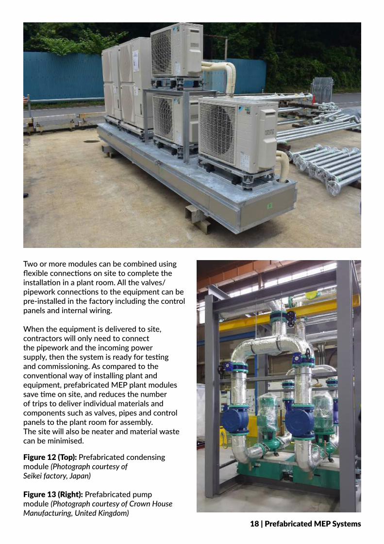
Two or more modules can be combined using flexible connections on site to complete the installation in a plant room. All the valves/pipework connections to the equipment can be pre-installed in the factory including the control panels and internal wiring.
When the equipment is delivered to site, contractors will only need to connect the pipework and the incoming power supply, then the system is ready for testing and commissioning. As compared to the conventional way of installing plant and equipment, prefabricated MEP plant modules save time on site, and reduces the number of trips to deliver individual materials and components such as valves, pipes and control panels to the plant room for assembly. The site will also be neater and material waste can be minimised.
Figure 12 (Top): Prefabricated condensing module (Photograph courtesy of Seikei factory, Japan)
Figure 13 (Right): Prefabricated pump module (Photograph courtesy of Crown House Manufacturing, United Kingdom)
18 | Prefabricated MEP Systems
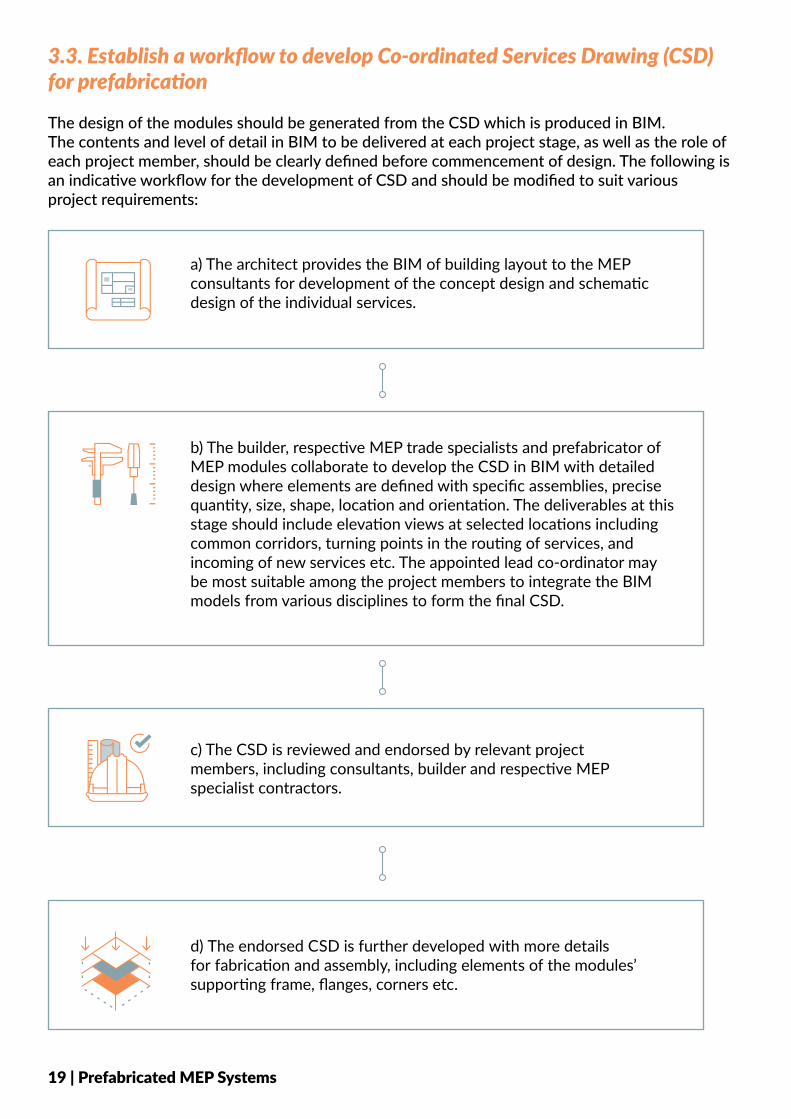
The design of the modules should be generated from the CSD which is produced in BIM. The contents and level of detail in BIM to be delivered at each project stage, as well as the role of each project member, should be clearly defined before commencement of design. The following is an indicative workflow for the development of CSD and should be modified to suit various project requirements:
3.3. Establish a workflow to develop Co-ordinated Services Drawing (CSD) for prefabrication
19 | Prefabricated MEP Systems
a) The architect provides the BIM of building layout to the MEP consultants for development of the concept design and schematic design of the individual services.
b) The builder, respective MEP trade specialists and prefabricator of MEP modules collaborate to develop the CSD in BIM with detailed design where elements are defined with specific assemblies, precise quantity, size, shape, location and orientation. The deliverables at this stage should include elevation views at selected locations including common corridors, turning points in the routing of services, and incoming of new services etc. The appointed lead co-ordinator maybe most suitable among the project members to integrate the BIM models from various disciplines to form the final CSD.
c) The CSD is reviewed and endorsed by relevant projectmembers, including consultants, builder and respective MEP specialist contractors.
d) The endorsed CSD is further developed with more detailsfor fabrication and assembly, including elements of the modules’supporting frame, flanges, corners etc.
4. GOOD INDUSTRY PRACTICES - FABRICATION AT THE MANUFACTURING PLANT
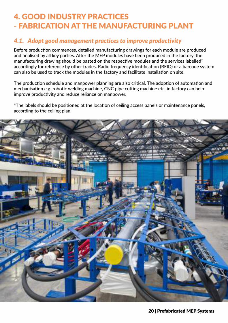
Before production commences, detailed manufacturing drawings for each module are produced and finalised by all key parties. After the MEP modules have been produced in the factory, the manufacturing drawing should be pasted on the respective modules and the services labelled* accordingly for reference by other trades. Radio frequency identification (RFID) or a barcode system can also be used to track the modules in the factory and facilitate installation on site.
The production schedule and manpower planning are also critical. The adoption of automation and mechanisation e.g. robotic welding machine, CNC pipe cutting machine etc. in factory can help improve productivity and reduce reliance on manpower.
*The labels should be positioned at the location of ceiling access panels or maintenance panels, according to the ceiling plan.
4.1. Adopt good management practices to improve productivity
20 | Prefabricated MEP Systems
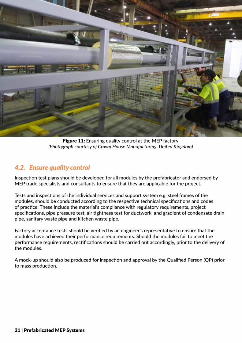
Inspection test plans should be developed for all modules by the prefabricator and endorsed by MEP trade specialists and consultants to ensure that they are applicable for the project.
Tests and inspections of the individual services and support system e.g. steel frames of the modules, should be conducted according to the respective technical specifications and codes of practice. These include the material’s compliance with regulatory requirements, project specifications, pipe pressure test, air tightness test for ductwork, and gradient of condensate drain pipe, sanitary waste pipe and kitchen waste pipe.
Factory acceptance tests should be verified by an engineer’s representative to ensure that the modules have achieved their performance requirements. Should the modules fail to meet the performance requirements, rectifications should be carried out accordingly, prior to the delivery of the modules.
A mock-up should also be produced for inspection and approval by the Qualified Person (QP) prior to mass production.
4.2. Ensure quality control
21 | Prefabricated MEP Systems
Figure 11: Ensuring quality control at the MEP factory (Photograph courtesy of Crown House Manufacturing, United Kingdom)
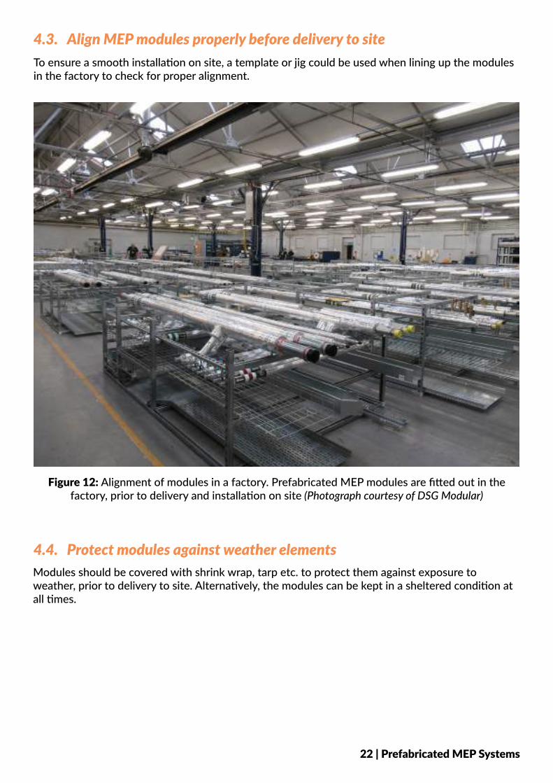
To ensure a smooth installation on site, a template or jig could be used when lining up the modules in the factory to check for proper alignment.
4.3. Align MEP modules properly before delivery to site
Figure 12: Alignment of modules in a factory. Prefabricated MEP modules are fitted out in the factory, prior to delivery and installation on site (Photograph courtesy of DSG Modular)
4.4. Protect modules against weather elementsModules should be covered with shrink wrap, tarp etc. to protect them against exposure to weather, prior to delivery to site. Alternatively, the modules can be kept in a sheltered condition at all times.
22 | Prefabricated MEP Systems
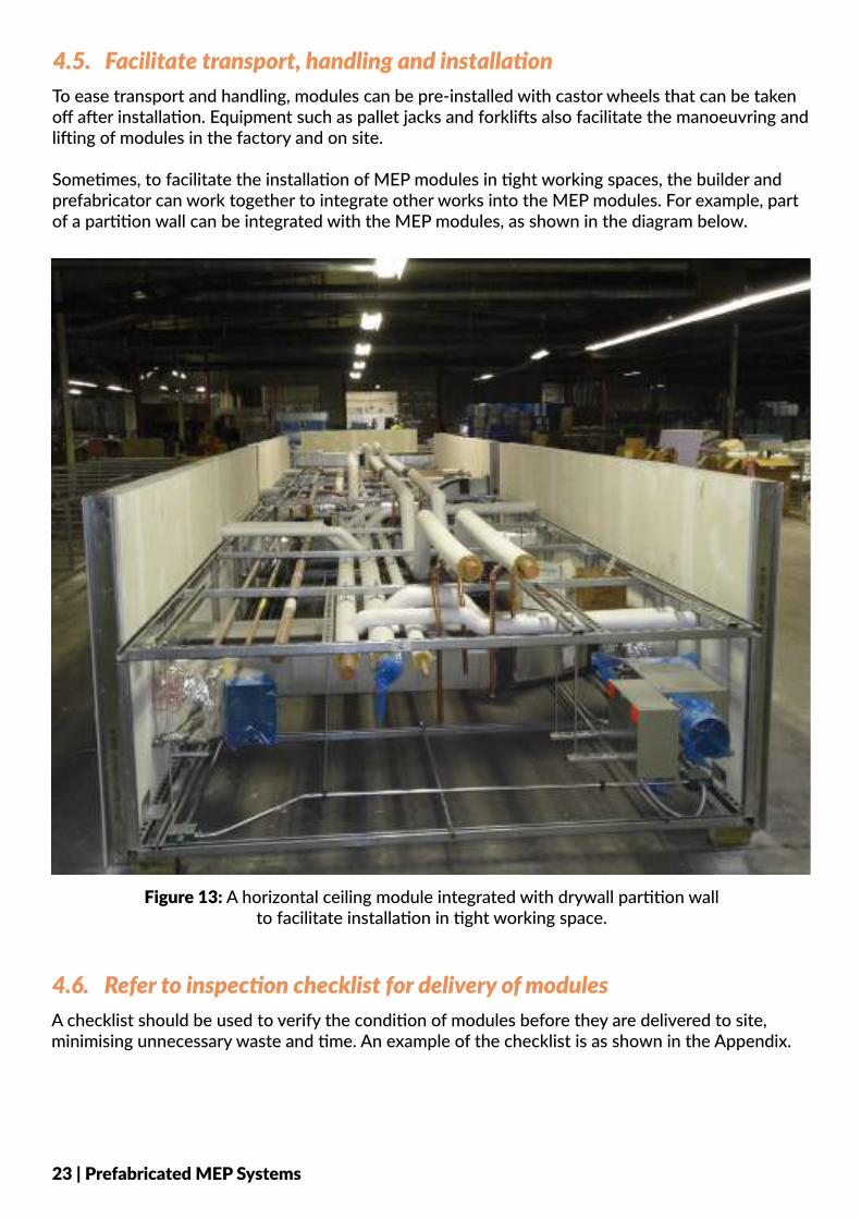
4.5. Facilitate transport, handling and installationTo ease transport and handling, modules can be pre-installed with castor wheels that can be taken off after installation. Equipment such as pallet jacks and forklifts also facilitate the manoeuvring and lifting of modules in the factory and on site.
Sometimes, to facilitate the installation of MEP modules in tight working spaces, the builder and prefabricator can work together to integrate other works into the MEP modules. For example, part of a partition wall can be integrated with the MEP modules, as shown in the diagram below.
Figure 13: A horizontal ceiling module integrated with drywall partition wall to facilitate installation in tight working space.
4.6. Refer to inspection checklist for delivery of modulesA checklist should be used to verify the condition of modules before they are delivered to site, minimising unnecessary waste and time. An example of the checklist is as shown in the Appendix.
23 | Prefabricated MEP Systems
5. GOOD INDUSTRY PRACTICES - INSTALLATION5.1. Adopt Just-In-Time (JIT) conceptAdopting a just-in-time (JIT) concept, where MEP modules are delivered according to the construction sequence, eliminates congestion in the factory and minimises damages to the modules on site. BIM can be used to simulate the actual on-site installation to identify potential problems in the access route.
Close co-ordination between parties at the project site and factory is critical to ensure a smooth supply of modules to the site and minimise downtime due to missing modules on site.
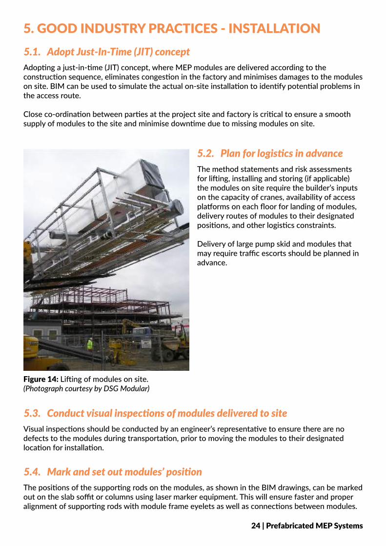
5.2. Plan for logistics in advanceThe method statements and risk assessments for lifting, installing and storing (if applicable) the modules on site require the builder’s inputs on the capacity of cranes, availability of access platforms on each floor for landing of modules, delivery routes of modules to their designated positions, and other logistics constraints.
Delivery of large pump skid and modules that may require traffic escorts should be planned in advance.
5.3. Conduct visual inspections of modules delivered to siteVisual inspections should be conducted by an engineer’s representative to ensure there are no defects to the modules during transportation, prior to moving the modules to their designated location for installation.
Figure 14: Lifting of modules on site. (Photograph courtesy by DSG Modular)
5.4. Mark and set out modules’ positionThe positions of the supporting rods on the modules, as shown in the BIM drawings, can be marked out on the slab soffit or columns using laser marker equipment. This will ensure faster and proper alignment of supporting rods with module frame eyelets as well as connections between modules.
24 | Prefabricated MEP Systems
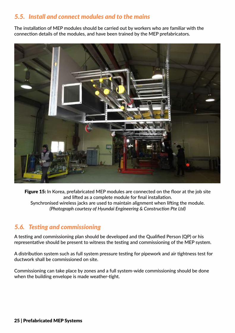
5.5. Install and connect modules and to the mainsThe installation of MEP modules should be carried out by workers who are familiar with the connection details of the modules, and have been trained by the MEP prefabricators.
A lifting plan should be developed to ensure the carnage, hoist, module and lifting fixture are positioned correctly. Final positioning is critical to achieve the levelling tolerance of the MEP services.
The horizontal ceiling modules can also be pre-assembled on the floor on site, before simultaneously lifting multiple connected modules to the ceiling.
5.6. Testing and commissioningA testing and commissioning plan should be developed and the Qualified Person (QP) or his representative should be present to witness the testing and commissioning of the MEP system.
A distribution system such as full system pressure testing for pipework and air tightness test for ductwork shall be commissioned on site.
Commissioning can take place by zones and a full system-wide commissioning should be done when the building envelope is made weather-tight.
Figure 15: In Korea, prefabricated MEP modules are connected on the floor at the job site and lifted as a complete module for final installation.
Synchronised wireless jacks are used to maintain alignment when lifting the module. (Photograph courtesy of Hyundai Engineering & Construction Pte Ltd)
25 | Prefabricated MEP Systems
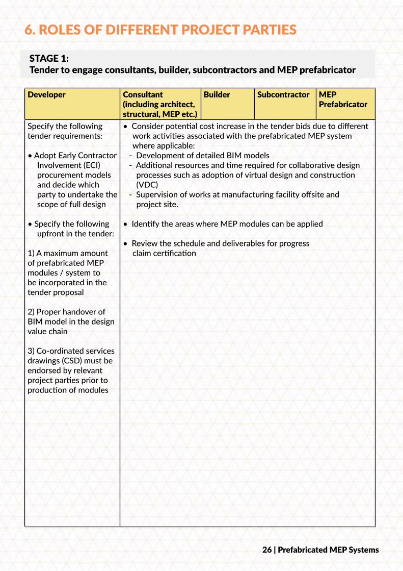
6. ROLES OF DIFFERENT PROJECT PARTIES
Developer Consultant (including architect, structural, MEP etc.)
Builder Subcontractor MEP Prefabricator
Specify the following tender requirements:
• Adopt Early Contractor Involvement (ECI) procurement models and decide which party to undertake the scope of full design
• Specify the following upfront in the tender:
1) A maximum amount of prefabricated MEP modules / system to be incorporated in the tender proposal
2) Proper handover of BIM model in the design value chain
3) Co-ordinated services drawings (CSD) must be endorsed by relevant project parties prior to production of modules
• Consider potential cost increase in the tender bids due to different work activities associated with the prefabricated MEP system where applicable:
- Development of detailed BIM models - Additional resources and time required for collaborative design
processes such as adoption of virtual design and construction (VDC)
- Supervision of works at manufacturing facility offsite and project site.
• Identify the areas where MEP modules can be applied
• Review the schedule and deliverables for progress claim certification
STAGE 1: Tender to engage consultants, builder, subcontractors and MEP prefabricator
26 | Prefabricated MEP Systems
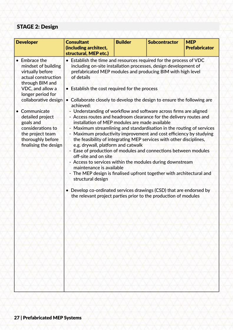
Developer Consultant (including architect, structural, MEP etc.)
Builder Subcontractor MEP Prefabricator
• Embrace the mindset of building virtually before actual construction through BIM and VDC, and allow a longer period for collaborative design
• Communicate detailed project goals and considerations to the project team thoroughly before finalising the design
• Establish the time and resources required for the process of VDC including on-site installation processes, design development of prefabricated MEP modules and producing BIM with high level of details
• Establish the cost required for the process
• Collaborate closely to develop the design to ensure the following are achieved:
- Understanding of workflow and software across firms are aligned - Access routes and headroom clearance for the delivery routes and
installation of MEP modules are made available - Maximum streamlining and standardisation in the routing of services - Maximum productivity improvement and cost efficiency by studying
the feasibility of integrating MEP services with other disciplines, e.g. drywall, platform and catwalk
- Ease of production of modules and connections between modules off-site and on site
- Access to services within the modules during downstream maintenance is available
- The MEP design is finalised upfront together with architectural and structural design
• Develop co-ordinated services drawings (CSD) that are endorsed by the relevant project parties prior to the production of modules
STAGE 2: Design
27 | Prefabricated MEP Systems
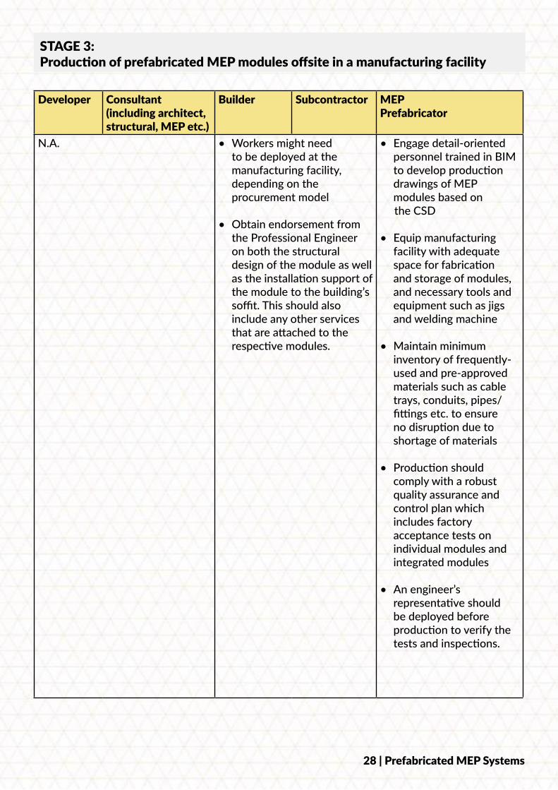
Developer Consultant (including architect, structural, MEP etc.)
Builder Subcontractor MEP Prefabricator
N.A. • Workers might need to be deployed at the manufacturing facility, depending on the procurement model
• Obtain endorsement from the Professional Engineer on both the structural design of the module as well as the installation support of the module to the building’s soffit. This should also include any other services that are attached to the respective modules.
• Engage detail-oriented personnel trained in BIM to develop production drawings of MEP modules based on
the CSD
• Equip manufacturing facility with adequate space for fabrication and storage of modules, and necessary tools and equipment such as jigs and welding machine
• Maintain minimum inventory of frequently-used and pre-approved materials such as cable trays, conduits, pipes/ fittings etc. to ensure no disruption due to shortage of materials
• Production should comply with a robust quality assurance and control plan which includes factory acceptance tests on individual modules and integrated modules
• An engineer’s representative should be deployed before production to verify the tests and inspections.
STAGE 3: Production of prefabricated MEP modules offsite in a manufacturing facility
28 | Prefabricated MEP Systems
Developer Consultant (including architect, structural, MEP etc.)
Builder Subcontractor MEP Prefabricator
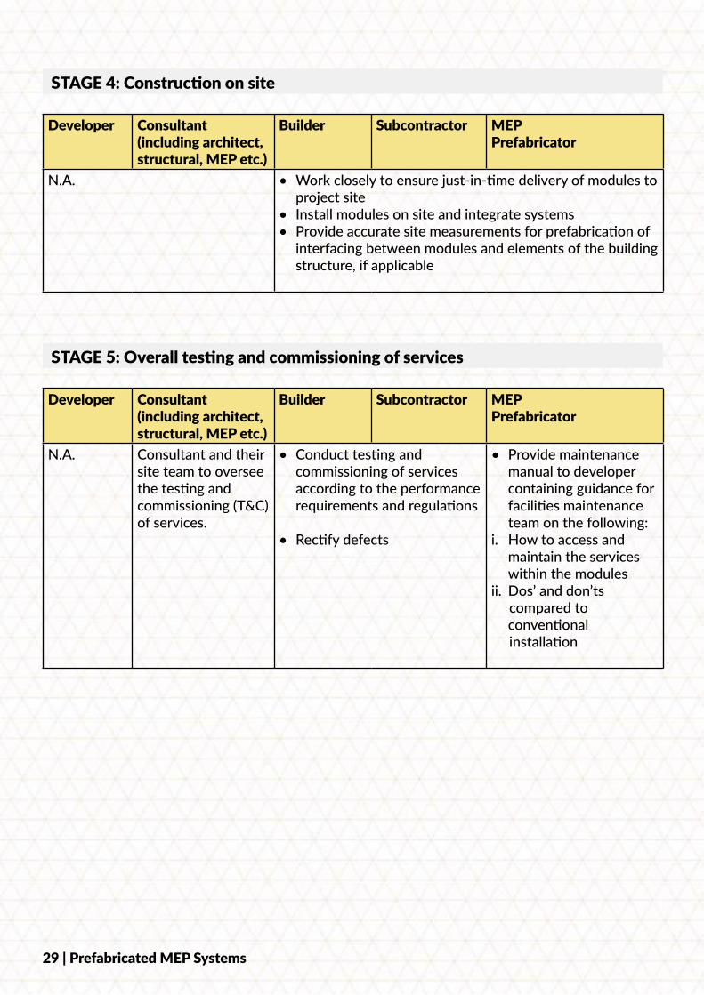
N.A. • Work closely to ensure just-in-time delivery of modules to project site
• Install modules on site and integrate systems• Provide accurate site measurements for prefabrication of
interfacing between modules and elements of the building structure, if applicable
STAGE 4: Construction on site
Developer Consultant (including architect, structural, MEP etc.)
Builder Subcontractor MEP Prefabricator
N.A. Consultant and their site team to oversee the testing and commissioning (T&C) of services.
• Conduct testing and commissioning of services according to the performance requirements and regulations
• Rectify defects
• Provide maintenance manual to developer containing guidance for facilities maintenance team on the following:
i. How to access and maintain the services within the modules
ii. Dos’ and don’ts compared to
conventional installation
STAGE 5: Overall testing and commissioning of services
29 | Prefabricated MEP Systems
7. OVERSEAS AND LOCAL PROJECTS
7.1. Crossrail Tottenham Court Road Station
7.1.1. Background
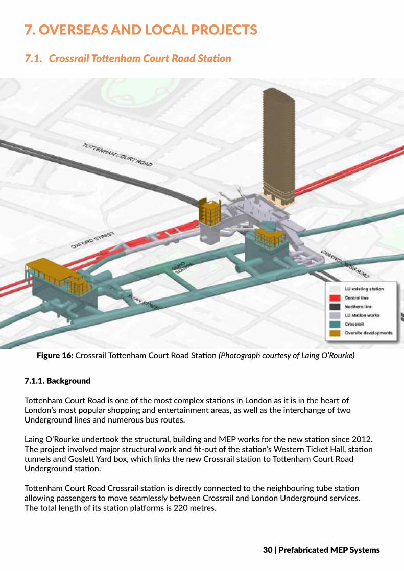
Tottenham Court Road is one of the most complex stations in London as it is in the heart of London’s most popular shopping and entertainment areas, as well as the interchange of two Underground lines and numerous bus routes. Laing O’Rourke undertook the structural, building and MEP works for the new station since 2012. The project involved major structural work and fit-out of the station’s Western Ticket Hall, station tunnels and Goslett Yard box, which links the new Crossrail station to Tottenham Court Road Underground station. Tottenham Court Road Crossrail station is directly connected to the neighbouring tube station allowing passengers to move seamlessly between Crossrail and London Underground services. The total length of its station platforms is 220 metres.
Figure 16: Crossrail Tottenham Court Road Station (Photograph courtesy of Laing O’Rourke)
30 | Prefabricated MEP Systems
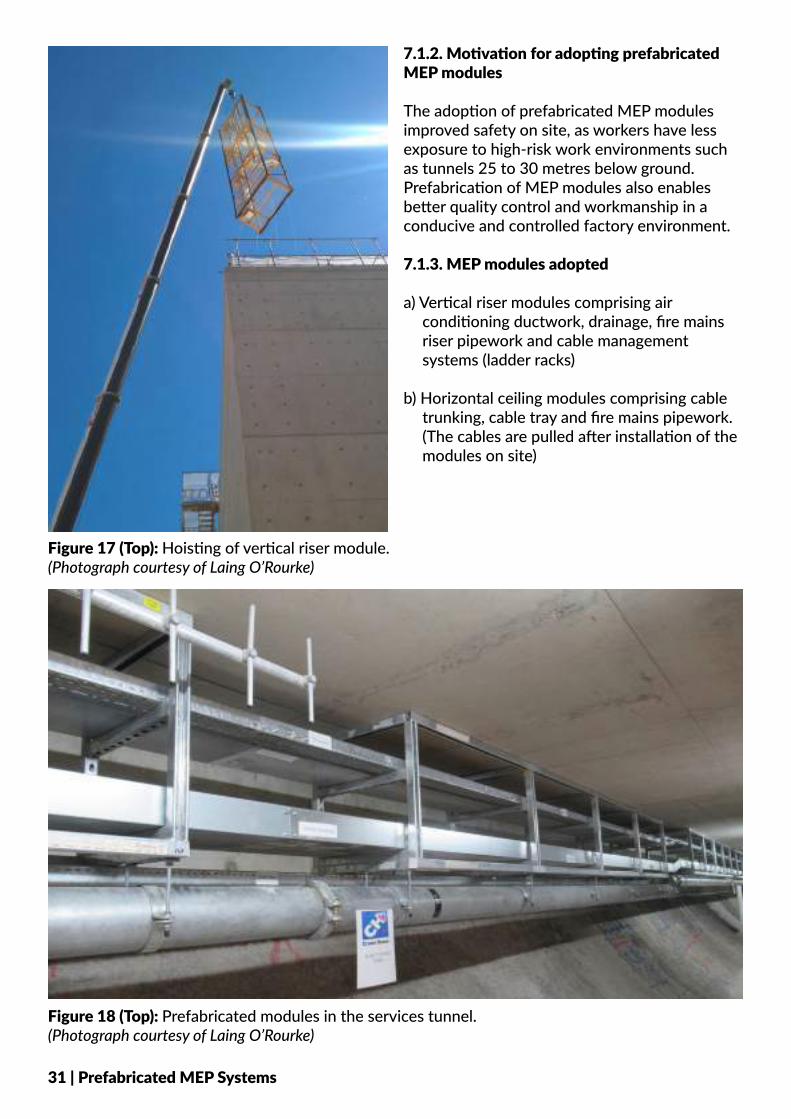
7.1.2. Motivation for adopting prefabricated MEP modules
The adoption of prefabricated MEP modules improved safety on site, as workers have less exposure to high-risk work environments such as tunnels 25 to 30 metres below ground. Prefabrication of MEP modules also enables better quality control and workmanship in a conducive and controlled factory environment.
7.1.3. MEP modules adopted
a) Vertical riser modules comprising air conditioning ductwork, drainage, fire mains riser pipework and cable management systems (ladder racks)
b) Horizontal ceiling modules comprising cable trunking, cable tray and fire mains pipework. (The cables are pulled after installation of the modules on site)
Figure 18 (Top): Prefabricated modules in the services tunnel. (Photograph courtesy of Laing O’Rourke)
Figure 17 (Top): Hoisting of vertical riser module. (Photograph courtesy of Laing O’Rourke)
31 | Prefabricated MEP Systems
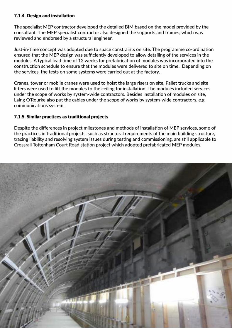
7.1.4. Design and installation
The specialist MEP contractor developed the detailed BIM based on the model provided by the consultant. The MEP specialist contractor also designed the supports and frames, which was reviewed and endorsed by a structural engineer.
Just-in-time concept was adopted due to space constraints on site. The programme co-ordination ensured that the MEP design was sufficiently developed to allow detailing of the services in the modules. A typical lead time of 12 weeks for prefabrication of modules was incorporated into the construction schedule to ensure that the modules were delivered to site on time. Depending on the services, the tests on some systems were carried out at the factory.
Cranes, tower or mobile cranes were used to hoist the large risers on site. Pallet trucks and site lifters were used to lift the modules to the ceiling for installation. The modules included services under the scope of works by system-wide contractors. Besides installation of modules on site, Laing O’Rourke also put the cables under the scope of works by system-wide contractors, e.g. communications system.
7.1.5. Similar practices as traditional projects
Despite the differences in project milestones and methods of installation of MEP services, some of the practices in traditional projects, such as structural requirements of the main building structure, tracing liability and resolving system issues during testing and commissioning, are still applicable to Crossrail Tottenham Court Road station project which adopted prefabricated MEP modules.
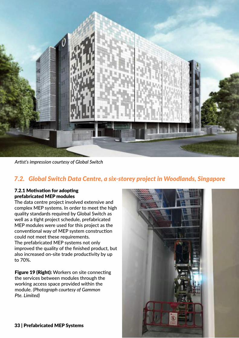
7.2. Global Switch Data Centre, a six-storey project in Woodlands, Singapore7.2.1 Motivation for adopting prefabricated MEP modulesThe data centre project involved extensive and complex MEP systems. In order to meet the high quality standards required by Global Switch as well as a tight project schedule, prefabricated MEP modules were used for this project as the conventional way of MEP system construction could not meet these requirements. The prefabricated MEP systems not only improved the quality of the finished product, but also increased on-site trade productivity by up to 70%.
33 | Prefabricated MEP Systems
Artist’s impression courtesy of Global Switch
Figure 19 (Right): Workers on site connecting the services between modules through the working access space provided within the module. (Photograph courtesy of Gammon Pte. Limited)
Artist’s impression courtesy of Global Switch
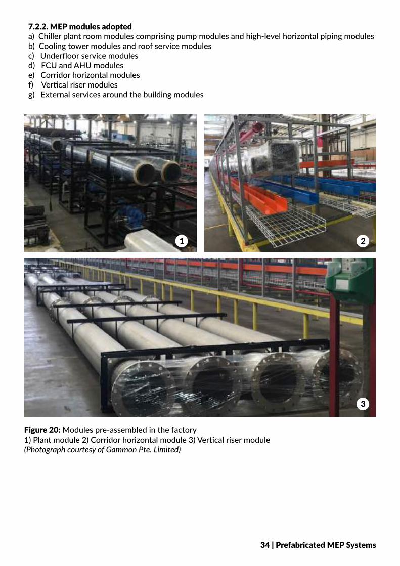
Figure 20: Modules pre-assembled in the factory1) Plant module 2) Corridor horizontal module 3) Vertical riser module (Photograph courtesy of Gammon Pte. Limited)
7.2.2. MEP modules adopteda) Chiller plant room modules comprising pump modules and high-level horizontal piping modulesb) Cooling tower modules and roof service modulesc) Underfloor service modulesd) FCU and AHU modulese) Corridor horizontal modulesf) Vertical riser modulesg) External services around the building modules
1 2
3
34 | Prefabricated MEP Systems
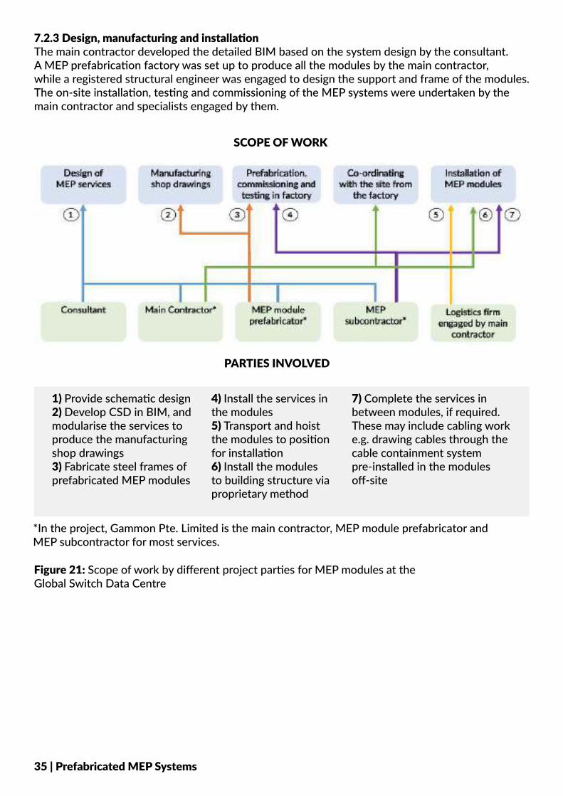
7.2.3 Design, manufacturing and installationThe main contractor developed the detailed BIM based on the system design by the consultant. A MEP prefabrication factory was set up to produce all the modules by the main contractor,while a registered structural engineer was engaged to design the support and frame of the modules. The on-site installation, testing and commissioning of the MEP systems were undertaken by the main contractor and specialists engaged by them.
Figure 21: Scope of work by different project parties for MEP modules at the Global Switch Data Centre
SCOPE OF WORK
PARTIES INVOLVED
1) Provide schematic design2) Develop CSD in BIM, and modularise the services to produce the manufacturing shop drawings3) Fabricate steel frames of prefabricated MEP modules
4) Install the services in the modules5) Transport and hoist the modules to position for installation6) Install the modules to building structure via proprietary method
7) Complete the services in between modules, if required. These may include cabling work e.g. drawing cables through the cable containment system pre-installed in the modules off-site
*In the project, Gammon Pte. Limited is the main contractor, MEP module prefabricator and MEP subcontractor for most services.
35 | Prefabricated MEP Systems
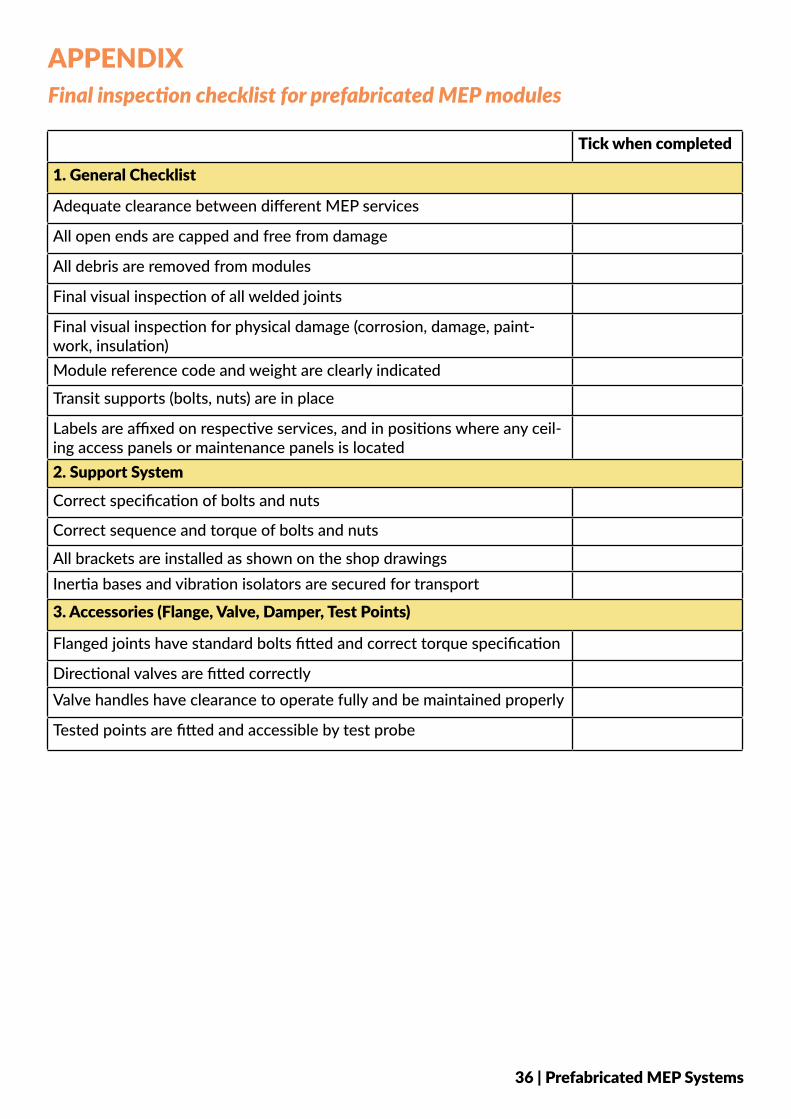
Tick when completed
1. General Checklist
Adequate clearance between different MEP services
All open ends are capped and free from damage
All debris are removed from modules
Final visual inspection of all welded joints
Final visual inspection for physical damage (corrosion, damage, paint-work, insulation)Module reference code and weight are clearly indicated
Transit supports (bolts, nuts) are in place
Labels are affixed on respective services, and in positions where any ceil-ing access panels or maintenance panels is located2. Support System
Correct specification of bolts and nuts
Correct sequence and torque of bolts and nuts
All brackets are installed as shown on the shop drawingsInertia bases and vibration isolators are secured for transport
3. Accessories (Flange, Valve, Damper, Test Points)
Flanged joints have standard bolts fitted and correct torque specification
Directional valves are fitted correctlyValve handles have clearance to operate fully and be maintained properly
Tested points are fitted and accessible by test probe
APPENDIXFinal inspection checklist for prefabricated MEP modules
36 | Prefabricated MEP Systems