display, operate, switch, control, regulate and communicate
TRANSCRIPT

Think future. Switch to green.
Belt 1: 356 pcs.
PC based HMI-PLCand PLC
Embedded HMI-PLC
Modular PLC
Compact PLC
HMI
Remote I/O
Operator- andcontrol relays
Automation products, system solutions and services. The recognisedbrand name all around the PLC, enhancing the performance of machinesand systems.
Display, Operate, Switch, Control, Regulate and Communicate
Product Informationeasy500, 700, 800 Control RelaysMFD-Titan® Multi-Function Display

2
ºC
t
Easy OperationWith Maximum Benefits
easy control relays provide many basic functions that users could previously onlyimplement with conventional devices that were individually installed and wired. Inaddition to this, the MFD-Titan multi-function display offers powerful visualizationfunctions as well.
Thanks to the extensive range of the device series you arealways sure of finding the right device for your specificrequirements. This range extends from the compact stand-alonecontrol relay with a few timing relays and a time switch to large-scale networked applications, processing several hundreds of
I/O with local and remote expansion modules and graphicvisualization. The demand for user-friendly operation andprogramming is consistently met and forms the basis of theoutstanding features of easy and MFD-Titan, with particularimportance being placed on simple circuit diagram input.
3
Easy really is easy and, in conjunction with MFD-Titan, offers everything you require from a state-of-the-art
automation system: flexible networking, local and remote expansion modules, visualization, scalability,
customised inscriptions etc...
Simplicity as a concept
The easy and MFD-Titan device series stands out with its user-friendly operation andprogramming, with particular importance being placed on simple circuit diagraminput. Every rung or circuit connection is wired in the same way as it was taught inschools and colleges: Contact – Contact – Contact – Coil; Done! The devices allowthe “wiring” of 128 or 256 rungs or circuit connections for this purpose. Series andparallel connections, which normally make up the major part of a control circuit, canbe created easily without any particular programming knowledge. Ready-to-usefunction blocks that are simply integrated in the wiring with coils and contacts arealso provided for additional functions.
Everything on board
Depending on the device selected, easy and MFD-Titan devices can provide userswith timing relays, flash relays, counters, comparators, time switches and many otherready-to-use function blocks, right up to powerful PID controllers. The circuitdiagram display of series and parallel connections, unlike the display of AND and ORoperations in FBD, offers the user a considerably more manageable display of the circuit. Every easy control relay and MFD-Titan features an integrated power flowdisplay that ensures the safe operation of the circuit diagram during commissioningand helps to identify errors in the circuit diagram initially created. This clearlyhighlights every energized rung and dims those which are not energized.
Safety means safety
The finished circuit diagram is stored internally (retentively) and can also be savedexternally on a memory module (EEPROM) together with all set parameters, fortransport, security and backup. A multi-level password protection secures your circuitdiagram against unauthorised viewing, editing, copying or deleting as required. easyor MFD-Titan offer menu-driven interactive operation which can be carried out inten different languages. The very large operating temperature range from -25 to+55°C for all easy and MFD-Titan control relays means that the devices can be run ina wide range of machines and systems.
4
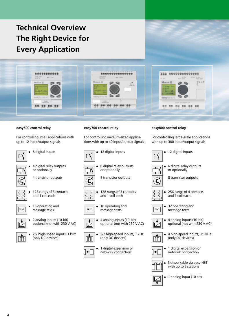
easy500 control relay
For controlling small applications withup to 12 input/output signals
8 digital inputs
4 digital relay outputsor optionally
4 transistor outputs
128 rungs of 3 contactsand 1 coil each
16 operating and message texts
2 analog inputs (10-bit)optional (not with 230 V AC)
2/2 high-speed inputs, 1 kHz(only DC devices)
easy700 control relay
For controlling medium-sized applica-tions with up to 40 input/output signals
12 digital inputs
6 digital relay outputsor optionally
8 transistor outputs
128 rungs of 3 contactsand 1 coil each
16 operating and message texts
4 analog inputs (10-bit)optional (not with 230 V AC)
2/2 high-speed inputs, 1 kHz(only DC devices)
1 digital expansion or network connection
easy800 control relay
For controlling large-scale applicationswith up to 300 input/output signals
12 digital inputs
6 digital relay outputsor optionally
8 transistor outputs
256 rungs of 4 contactsand 1 coil each
32 operating and message texts
4 analog inputs (10-bit)optional (not with 230 V AC)
4 high-speed inputs, 3/5 kHz(only DC devices)
1 digital expansion or network connection
Networkable via easy-NETwith up to 8 stations
1 analog input (10 bit)
Technical OverviewThe Right Device for Every Application

5
Fill level
90%
MFD-Titan multi-function display
For controlling large-scale applicationswith powerful visualization functions
12 digital inputs
4 digital relay outputsor optionally
4 transistor outputs
256 rungs of 4 contactsand 1 coil each
24 KB mask memory on afully graphical, backlit display (64 x 132 pixels)
4 analog inputs (10-bit)optional (not with 230 V AC)
4 high-speed inputs, 3/5 kHz(only DC devices)
1 digital expansion or network connection
Networkable via easy-NETwith up to 8 stations
1 analog input (10 bit)
easy800 control relay and MFD-Titan
The easy800 control relay and MFD-Titan combine virtually all the featuresof a PLC with the user-friendlyoperating features of the well-knownEasy product line. Thanks to theirintegrated networking capability for upto eight devices, applications with over300 I/O points can be implemented. Thecontrol system can be designed eitherusing a single local program or usingseveral programs on the differentdistributed devices. Up to 1000 metrescan be covered by the network. Thecontrol relays can also be integratedeasily in higher-level automationnetworks thanks to the networkingmodules available (for PROFIBUS DP,CANopen, DeviceNet, AS-Interface).
MFD-Titan multi-function display
The MFD-Titan supports all thefunctions of the easy800 and alsoprovides a fully graphical display. Itreplaces 7 segment displays and canindicate fault messages and operatingsteps graphically or in plain text. Thefunction buttons on the MFD-Titan canbe used for displaying and modifyingsetpoints during operation. High-speedsignal counting, frequencymeasurement, incremental encoderprocessing can all be implemented witheasy800 and MFD-Titan without anyproblems. Maths functions, datastorage or communication via the NETnetwork – all simply easy.
MFD-AC-CP8 and MFD-AC-R16
A new addition to the MFD-Titanfamily! The MFD-AC-CP8 power supplyand CPU modules now also provideusers with 230 V AC versions for theirapplications. As with the already known24 V DC version, a power supply/CPUmodule is available without easy-NET(MFD-AC-CP8-ME) and with easy-NET(MFD-AC-CP8-NT). If users also require230 V AC inputs for their MFD-Titanapplications, Moeller can now offer theMFD-AC-R16 I/O module incombination with the two MFD-AC-CP8power supply/CPU modules. Thistherefore provides 12 inputs and 4 relayoutputs.
6
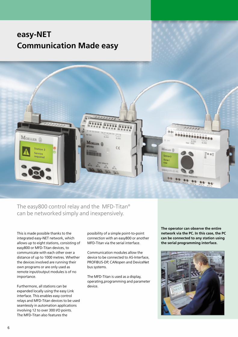
easy-NETCommunication Made easy
This is made possible thanks to theintegrated easy-NET network, whichallows up to eight stations, consisting ofeasy800 or MFD-Titan devices, tocommunicate with each other over adistance of up to 1000 metres. Whetherthe devices involved are running theirown programs or are only used asremote input/output modules is of noimportance.
Furthermore, all stations can beexpanded locally using the easy Linkinterface. This enables easy controlrelays and MFD-Titan devices to be usedseamlessly in automation applicationsinvolving 12 to over 300 I/O points.The MFD-Titan also features the
possibility of a simple point-to-pointconnection with an easy800 or anotherMFD-Titan via the serial interface.
Communication modules allow thedevice to be connected to AS-Interface,PROFIBUS-DP, CANopen and DeviceNetbus systems.
The MFD-Titan is used as a display,operating,programming and parameterdevice.
The easy800 control relay and the MFD-Titan®
can be networked simply and inexpensively.
The operator can observe the entirenetwork via the PC. In this case, the PCcan be connected to any station usingthe serial programming interface.
Station 3Motor 1 fuse
Station 3Service required
7
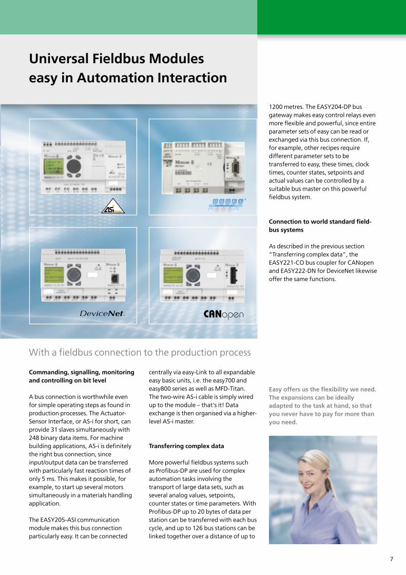
With a fieldbus connection to the production process
Universal Fieldbus Moduleseasy in Automation Interaction
Commanding, signalling, monitoringand controlling on bit level
A bus connection is worthwhile even for simple operating steps as found inproduction processes. The Actuator-Sensor Interface, or AS-i for short, canprovide 31 slaves simultaneously with248 binary data items. For machinebuilding applications, AS-i is definitelythe right bus connection, sinceinput/output data can be transferredwith particularly fast reaction times ofonly 5 ms. This makes it possible, forexample, to start up several motorssimultaneously in a materials handlingapplication.
The EASY205-ASI communicationmodule makes this bus connectionparticularly easy. It can be connected
centrally via easy-Link to all expandableeasy basic units, i.e. the easy700 andeasy800 series as well as MFD-Titan. The two-wire AS-i cable is simply wiredup to the module – that's it! Dataexchange is then organised via a higher-level AS-i master.
Transferring complex data
More powerful fieldbus systems such as Profibus-DP are used for complexautomation tasks involving thetransport of large data sets, such asseveral analog values, setpoints,counter states or time parameters. WithProfibus-DP up to 20 bytes of data perstation can be transferred with each buscycle, and up to 126 bus stations can belinked together over a distance of up to
Easy offers us the flexibility we need.The expansions can be ideallyadapted to the task at hand, so thatyou never have to pay for more thanyou need.
1200 metres. The EASY204-DP busgateway makes easy control relays evenmore flexible and powerful, since entireparameter sets of easy can be read orexchanged via this bus connection. If,for example, other recipes requiredifferent parameter sets to betransferred to easy, these times, clocktimes, counter states, setpoints andactual values can be controlled by asuitable bus master on this powerfulfieldbus system.
Connection to world standard field-bus systems
As described in the previous section“Transferring complex data”, theEASY221-CO bus coupler for CANopenand EASY222-DN for DeviceNet likewiseoffer the same functions.

8
1 2a
2b 3
“Stand-Alone” easy Display with High Degree ofProtection
easy product series now with stand-alone display to IP65
With the new MFD-CP4-500 / MFD-CP4-800 supply and communication module,Moeller is offering a stand-alone displaywith IP65 protection for all easy500/700and easy800 applications.
Plug & work
The plug & play technology allows usersto connect the MFD-Titan display (MFD-80 or MFD-80-B) to the easy controlrelay via the MFD-CP4 supply andcommunication module. With this inmind, the MFD-CP4 module is factoryshipped with five metres of serialconnection cable that can be cut to anyrequired length, thus allowing thedisplay to be run up to five metres awayfrom the control relay.
The benefits of this are multiple. Nosoftware or drivers are needed for theconnection since MFD-CP4 is a genuineplug & play device. The I/O wiring canbe kept in the control panel, andmounting the display is also easy thanksto the 2 x 22.5 mm fixing holesprovided. The display is protected toIP65, comes with a backlight and offersoptimum legibility.
Two versions are available for the easycontrol relays: MFD-CP4-500 is usedwith all easy500/700s, MFD-CP4-800with all easy800 and MFD-CP8 devices.
MFD-Titan the HMI-Control
When fitted with a power supply/CPUmodule and optional input/outputmodules, the display can also beexpanded into a compact HMI controldevice that then combines the completefunctionality of an easy800 withpowerful visualization functions. Thetwo modules are simply pluggedtogether. Plug & work
1 2a
1 2b 3

9
1 2 3
1
1
2
3
More Input/Output SignalsCentral and Decentralised Expansion Made easy
The expandable basicunits of the easy700,easy800 series and MFD-Titan® enablecentral and decentralisedI/O expansions to beimplemented.
Together with the EASY618-AC-RE, EASY618-DC-RE or EASY620-DC-TE expansion modules, youcan form a unit with 24 inputs andup to 16 outputs. These threeexpansion modules are simplyfitted onto the basic unit directlyand connected via the easy Linkinterface.
Alternatively, a connection can beset up using the EASY200-EASYcoupling module and up to 30metres of two-wire cable,enabling also extensive orexpanded configurations to be set up.
If that isn't enough, the EASY202-RE expansion module providestwo additional relay outputs.
10
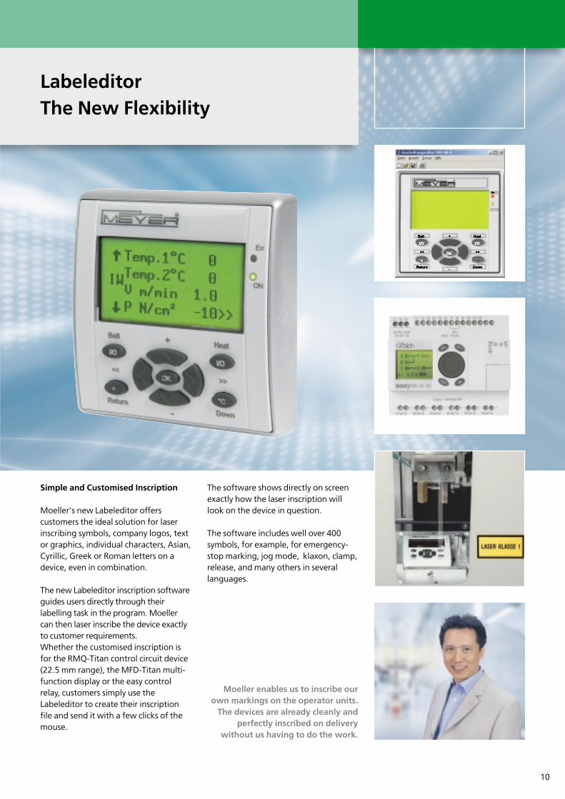
LabeleditorThe New Flexibility
Simple and Customised Inscription
Moeller's new Labeleditor offerscustomers the ideal solution for laserinscribing symbols, company logos, textor graphics, individual characters, Asian,Cyrillic, Greek or Roman letters on adevice, even in combination.
The new Labeleditor inscription softwareguides users directly through theirlabelling task in the program. Moellercan then laser inscribe the device exactlyto customer requirements. Whether the customised inscription isfor the RMQ-Titan control circuit device(22.5 mm range), the MFD-Titan multi-function display or the easy controlrelay, customers simply use theLabeleditor to create their inscriptionfile and send it with a few clicks of themouse.
The software shows directly on screenexactly how the laser inscription willlook on the device in question.
The software includes well over 400symbols, for example, for emergency-stop marking, jog mode, klaxon, clamp,release, and many others in severallanguages.
Moeller enables us to inscribe ourown markings on the operator units.
The devices are already cleanly andperfectly inscribed on delivery
without us having to do the work.

11
EASY512-AC-RC EASY512-DC-TCX EASY5
Basic units 500 basic units
Application Stand-alone operation
TypeOrder No.
EASY
512-
AB-RC
2741
01
EASY
512-
AB-RC
X
2741
02
EASY
512-
AC-R
2741
03
EASY
512-
AC-RC
2741
04
EASY
512-
AC-RC
X
2741
05
EASY
512-
DA-RC
2741
06
EASY
512-
DA-RCX
2741
07
EASY
512-
DC-R
2741
08
EASY
Supply voltage 24 V AC 100 - 240 V AC 12 V DC
Heat dissipation 5 VA 5 VA 2 W
Inputs, digital 8 8 8 8 8 8 8 8
Inputs, analog 0 - 10 V (optional) 2 2 - - - 2 2 2
Outputs, digital (R=relay,T=trans.) 4R 4R 4R 4R 4R 4R 4R 4R
Outputs, analog 0 - 10 V - - - - - - - -
LCD display / keypad Yes / Yes - / - Yes / Yes Yes / Yes - / - Yes / Yes - / - Yes / Yes Y
7-day / year time switch Yes / Yes Yes / Yes - / - Yes / Yes Yes / Yes Yes / Yes Yes / Yes - / - Y
Continuous current outputs [1] 8 A 8 A 8 A 8 A 8 A 8 A 8 A 8 A
Short-circuit proof with power factor 1 Line protection B16, 600 A
Short-circuit proof with power factor 0.7... 0.7 Line protection B16, 900 A
Connection cables 0.2 - 4.0 mm2 (AWG 22-12), solid0.2 - 2.5 mm2 (AWG 22-12), flexible
Degree of protection IP 20
RFI suppression EN 55011, EN 55022 Class B, IEC 61000-6-1, 2, 3, 4
Ambient operating temperature - 25 °C ... + 55 °C
Transport and storage temperature - 40 °C ... + 70 °C
Certification, standards EN 50178, IEC/EN 60947, UL, CSA
Mounting On top-hat rail to DIN 50022, 35 mmor screw mounting with ZB4-101-GF1 fixing brackets
Dimensions (W x H x D) mm 71.5 x 90 x 58 mm
[1] Relay = 8 A (10 A to UL) with resistive load, 3 A with inductive load/transistor outputs = 0.5 A / 24 V DC, max 4 outputs switchable in parallel[2] With backlight in continuous operation - 10 °C ... 0 °C[3] In stand-alone operation the MFD-...CP8-... CPU slices can also be mounted on a DIN 50022 top-hat rail, 35 mm or as screw mounting with ZB4-101-GF1 fixing brackets
Basic UnitsOverview and Selection
12
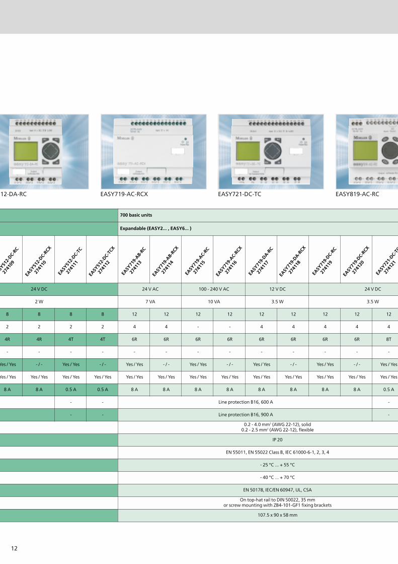
12-DA-RC EASY719-AC-RCX EASY721-DC-TC EASY819-AC-RC
700 basic units
Expandable (EASY2... , EASY6... )
ASY51
2-DC-
RC
2741
09
EASY
512-
DC-RC
X
2741
10
EASY
512-
DC-TC
2741
11
EASY
512-
DC-TC
X
2741
12
EASY
719-
AB-RC
2741
13
EASY
719-
AB-RC
X
2741
14
EASY
719-
AC-RC
2741
15
EASY
719-
AC-RC
X
2741
16
EASY
719-
DA-RC
2741
17
EASY
719-
DA-RCX
2741
18
EASY
719-
DC-RC
2741
19
EASY
719-
DC-RC
X
2741
20
EASY
721-
DC-TC
2741
21
24 V DC 24 V AC 100 - 240 V AC 12 V DC 24 V DC
2 W 7 VA 10 VA 3.5 W 3.5 W
8 8 8 8 12 12 12 12 12 12 12 12 12
2 2 2 2 4 4 - - 4 4 4 4 4
4R 4R 4T 4T 6R 6R 6R 6R 6R 6R 6R 6R 8T
- - - - - - - - - - - - -
Yes / Yes - / - Yes / Yes - / - Yes / Yes - / - Yes / Yes - / - Yes / Yes - / - Yes / Yes - / - Yes / Yes
Yes / Yes Yes / Yes Yes / Yes Yes / Yes Yes / Yes Yes / Yes Yes / Yes Yes / Yes Yes / Yes Yes / Yes Yes / Yes Yes / Yes Yes / Yes
8 A 8 A 0.5 A 0.5 A 8 A 8 A 8 A 8 A 8 A 8 A 8 A 8 A 0.5 A
- - Line protection B16, 600 A -
- - Line protection B16, 900 A -
0.2 - 4.0 mm2 (AWG 22-12), solid0.2 - 2.5 mm2 (AWG 22-12), flexible
IP 20
EN 55011, EN 55022 Class B, IEC 61000-6-1, 2, 3, 4
- 25 °C ... + 55 °C
- 40 °C ... + 70 °C
EN 50178, IEC/EN 60947, UL, CSA
On top-hat rail to DIN 50022, 35 mmor screw mounting with ZB4-101-GF1 fixing brackets
107.5 x 90 x 58 mm

13
EASY822-DC-TC MFD-80-B MFD-CP4
800 basic units MFD-Titan
Expandable (EASY2... , EASY6... ), networkable (easy-NET) Display
C
EASY
721-
DC-TC
X
2741
22
EASY
819-
AC-RC
2562
67
EASY
819-
AC-RC
X
2562
68
EASY
819-
DC-RC
2562
69
EASY
819-
DC-RC
X
2562
70
EASY
820-
DC-RC
2562
71
EASY
820-
DC-RC
X
2562
72
EASY
821-
DC-TC
2562
73
EASY
821-
DC-TC
X
2562
74
EASY
822-
DC-TC
2562
75
EASY
822-
DC-TC
X
2562
76 MFD
-80
2652
50
MF
100 - 240 V AC 24 V DC Supply via ...-C
10 VA 3.4 W 3 W
12 12 12 12 12 12 12 12 12 12 12 -
4 - - 4 4 4 4 4 4 4 4 -
8T 6R 6R 6R 6R 6R 6R 8T 8T 8T 8T -
- - - - - 1 1 - - 1 1 -
- / - Yes / Yes - / - Yes / Yes - / - Yes / Yes - / - Yes / Yes - / - Yes / Yes - / - Yes / - Ye
Yes / Yes Yes / Yes Yes / Yes Yes / Yes Yes / Yes Yes / Yes Yes / Yes Yes / Yes Yes / Yes Yes / Yes Yes / Yes - / -
0.5 A 8 A 8 A 8 A 8 A 8 A 8 A 0.5 A 0.5 A 0.5 A 0.5 A -
- Line protection B16, 600 A - - - - -
- Line protection B16, 900 A - - - - -
0.2 - 4.0 mm2 (AWG 22-12), solid0.2 - 2.5 mm2 (AWG 22-12), flexible -
IP 20 IP 65
EN 55011, EN 55022 Class B, IEC 61000-6-1, 2, 3, 4
- 25 °C ... + 55 °C Clearly legible- 5 °C ...+ 50 °C
- 40 °C ... + 70 °C
EN 50178, IEC/EN 60947, UL, CSA
On top-hat rail to DIN 50022, 35 mmor screw mounting with ZB4-101-GF1 fixing brackets
Front mounting 22.5 mm standard d
107.5 x 90 x 72 mm 86.5 x 86,5 x 20
14
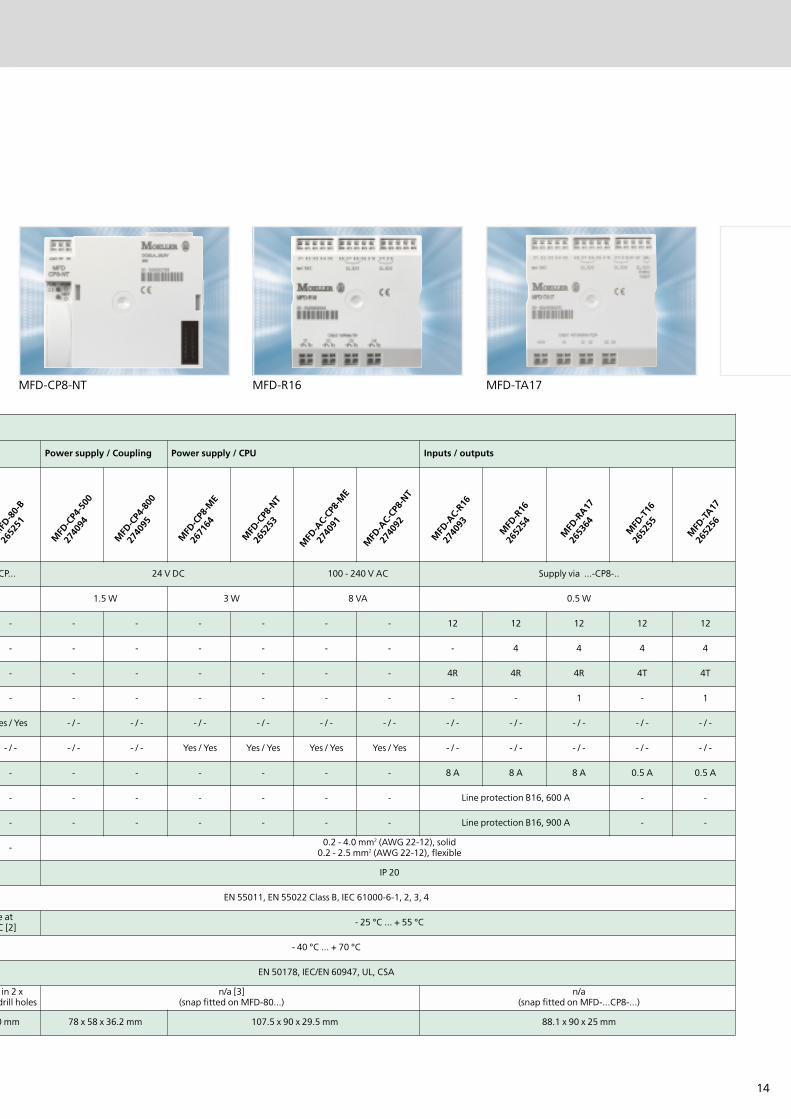
MFD-CP8-NT MFD-R16 MFD-TA17
Power supply / Coupling Power supply / CPU Inputs / outputs
MFD
-80-
B
2652
51
MFD
-CP4
-500
2740
94
MFD
-CP4
-800
2740
95
MFD
-CP8
-ME
2671
64
MFD
-CP8
-NT
2652
53
MFD
-AC-
CP8-
ME
2740
91
MFD
-AC-
CP8-
NT
2740
92
MFD
-AC-
R16
2740
93
MFD
-R16
2652
54
MFD
-RA17
2653
64
MFD
-T16
2652
55
MFD
-TA17
2652
56
CP... 24 V DC 100 - 240 V AC Supply via ...-CP8-..
1.5 W 3 W 8 VA 0.5 W
- - - - - - - 12 12 12 12 12
- - - - - - - - 4 4 4 4
- - - - - - - 4R 4R 4R 4T 4T
- - - - - - - - - 1 - 1
es / Yes - / - - / - - / - - / - - / - - / - - / - - / - - / - - / - - / -
- / - - / - - / - Yes / Yes Yes / Yes Yes / Yes Yes / Yes - / - - / - - / - - / - - / -
- - - - - - - 8 A 8 A 8 A 0.5 A 0.5 A
- - - - - - - Line protection B16, 600 A - -
- - - - - - - Line protection B16, 900 A - -
- 0.2 - 4.0 mm2 (AWG 22-12), solid0.2 - 2.5 mm2 (AWG 22-12), flexible
IP 20
EN 55011, EN 55022 Class B, IEC 61000-6-1, 2, 3, 4
e atC [2] - 25 °C ... + 55 °C
- 40 °C ... + 70 °C
EN 50178, IEC/EN 60947, UL, CSA
in 2 xdrill holes
n/a [3](snap fitted on MFD-80...)
n/a(snap fitted on MFD-...CP8-...)
0 mm 78 x 58 x 36.2 mm 107.5 x 90 x 29.5 mm 88.1 x 90 x 25 mm

15
EASY-SOFTThe User-Friendly Circuit Diagram Input
EASY-SOFT makes things particularly easy for users.The graphical editor shows the circuit diagramimmediately in the display format required.Selection menus and drag & drop functions simplifycircuit diagram creation. Simply select contacts andcoils and connect with the mouse – that's it!
In addition to the editing functionsavailable for the user on the devicesthemselves, the scaled softwarepackages EASY-SOFT-BASIC, EASY-SOFTand EASY-SOFT-PRO are available forstraightforward circuit diagram input.
The user-friendly menus and Helpscreens of EASY-SOFT can be called upin six different languages.
EASY-SOFT offers the following displayformats for viewing, editing andprinting out your program:
IEC format with contact and coilsymbols of the international standard
easy circuit diagram, a 1:1representation of the display in easy
ANSI format, in compliance with theAmerican standard
EASY-SOFT supports you inconfiguring, programming anddefining parameters for easy controlrelays, and in creating visualizationfunctions for the MFD-Titan. If controlrelays are connected to easy-NET, allconnected devices can be accessed andtheir programs loaded from a singlecontrol relay.
The integrated offline simulation toolallows the user to test the correctfunctioning of the circuit diagrambefore commissioning, without theneed for a connected device. Thecomment function for contacts, coilsand function blocks helps to provide a
clear overview of the circuit diagram. A cover sheet with a customisedcompany logo and different text fields,as well as the cross-reference list withcomments, can turn printouts into theperfect documentation for yourapplication.
easy is maintenance-free
The finished program is stored for everin easy's non-volatile memory or until itis modified. Additional auxiliary poweror a battery are not required. Thecontrol relays are thus entirelymaintenance-free.
Not only circuit diagrams andparameters are saved in the event of apower failure. easy also makes a note ofswitch positions or values. For example,the actual values of operating hoursmeters, counters and timing relays canbe processed further once power isrestored. The retentive function for thedifferent function blocks and data isavailable with all performance classes ofthe easy series.

16
EASY618-DC-RE EASY202-RE EASY204-DP EASY2
Accessories Expansion modules Expansion modules
Application Digital inputs / outputs Communication
TypeOrder No.
EASY
202-
RE
2321
86
EASY
618-
AC-RE
2123
14
EASY
618-
DC-RE
2321
12
EASY
620-
DC-TE
2123
13
EASY
200-
EASY
2123
15
EASY
204-
DP
2123
16
Supply voltage - 100 - 240 V AC 24 V DC - 24 V AC
Heat dissipation 1 W 10 VA 4 W 1 W 2 W
Inputs, digital - 12 12 12 - -
Inputs, analog 0 - 10 V (optional) - - - - - -
Outputs, digital (R=relay,T=trans.) 2R 6R 6R 8T - -
Outputs, analog 0 - 10 V - - - - - -
LCD display / keypad - / - - / - - / - - / - - / - -
7-day / year time switch - / - - / - - / - - / - - / - -
Continuous current outputs [1] 8 A 8 A 8 A 0.5 A - -
Short-circuit proof with power factor 1 Line protection B16, 600 A - - -
Short-circuit proof with power factor 0.7... 0.7 Line protection B16, 900 A - - -
Connection cables 0.2 - 4.0 mm2 (AWG 22-12), solid0.2 - 2.5 mm2 (AWG 22-12), flexible
0.2 - 40.2 - 2.
Degree of protection IP 20
RFI suppression EN 55011, EN 55022 Class B, IEC 61000-6-1, 2, 3, 4 EN 55011, EN 5
Ambient operating temperature - 25 °C ... + 55 °C
Transport and storage temperature - 40 °C ... + 70 °C
Certification, standards EN 50178, IEC/EN 60947, UL, CSA EN 50
Mounting On top-hat rail to DIN 50022, 35 mmor screw mounting with ZB4-101-GF1 fixing brackets
On top-or screw mount
Dimensions (W x H x D) mm 35.5 x 90 x 58 mm 107.5 x 90 x 58 mm
AccessoriesOverview and Selection
[1] Relay = 8 A (10 A to UL) with resistive load, 3 A with inductive load/transistor outputs = 0.5 A / 24 V DC, max 4 outputs switchable in parallel

17
205-ASI EASY221-CO EASY222-DN EASY200-POW EASY400-POW
Accessories Switched-mode power supply units
Application
EASY
200-
POW
2294
24
EASY
400-
POW
2123
19
Supply voltage 100 - 240 V AC
Maximum range 85 - 264 V AC
Output voltage 24 V DC (+/- 3%)
Output current (rated value) 0.25 A 1.25 A
Overcurrent limitation from 0.3 A 1.4 A
Short-circuit proof (secondary) Yes Yes
Overload proof Yes Yes
Potential isolation (prim./sec.) Yes, SELV(to EN 600950, VDE 805)
Others Additional outputvoltage 12 DC, 20 mA -
Connection cables 0.2 - 4.0 mm2 (AWG 22-12), solid0.2 - 2.5 mm2 (AWG 22-12), flexible
Degree of protection IP 20
RFI suppression EN 55011, EN 55022 Class B, IEC 61000-6-1, 2, 3, 4
Ambient operating temperature - 25 °C ... + 55 °C
Transport and storage temperature - 40 °C ... + 70 °C
Certification, standards EN 50178, IEC/EN 60947, UL, CSA
Mounting On top-hat rail to DIN 50022, 35 mm or screwmounting with ZB4-101-GF1 fixing brackets
Dimensions (W x H x D) mm 35.5 x 90 x 58 mm 71.5 x 90 x 58 mm
EASY
205-
ASI
2215
98
EASY
221-
CO
2335
39
EASY
222-
DN
2335
40
- 24 V AC 24 V AC
1 W 1 W 1 W
- - -
- - -
- - -
- - -
- - -
- - -
- - -
- - -
- - -
4.0 mm2 (AWG 22-12), solid5 mm2 (AWG 22-12), flexible
IP 20
55022 Class B, IEC 61000-6-1, 2, 3, 4
- 25 °C ... + 55 °C
- 40 °C ... + 70 °C
178, IEC/EN 60947, UL, CSA
-hat rail to DIN 50022, 35 mmting with ZB4-101-GF1 fixing brackets
35.5 x 90 x 58 mm

18
easyin Application
EASY 800: high pressure cleaning andrenovating
Falch Hochdruckstrahlsysteme GmbH is a company based in Merklingen inSouthwest Germany. With approxi-mately 65 employees, the companyproduces high pressure washers forworking pressures from 100 to 2000 bar.Its latest system, the TS20, operates witha water jet speed of over 2100 km/h anda pressure of up to 2000 bar, with anoperating weight of nearly 1800 kg.These mobile high pressure jet systemsare primarily used for cleaning andrenovating. State-of-the-art controltechnology is used for controlling andmonitoring the desired working pressureand provides up-to-date statusinformation about the system. Falchcarries out the development,engineering and assembly of the systemson its own. Service-friendly designs and aworldwide service are just asfundamental a requirement at Falch asan extensive range of system accessories.
Easy 820 controls the workingpressure of mobile high pressurewashers
Water jets offer an economical andenvironmentally-friendly alternative.Water jet cleaning using Falch's high-pressure technology is used wherevernew application fields are involved, inwhich the cutting performance ofconventional machines is insufficient orwhere the performance in manual
operation is uneconomical. It isprimarily used for cleaning andrenovating.
CleaningPaint removal from metals,
Rust removal from steel surfaceswithout the use of blasting agents,
Industrial cleaning, such as thecleaning of tanks and tubes.
RenovatingFast and careful removal of old paintcoatings on concrete
Cleaning of concrete surfaces,
Concrete removal, such as for bridgerenovations,
Concrete refurbishment, such as forexposing steel reinforcements.
The tasks listed can all be carried outwith water jets in an environmentally-friendly and economical way.Furthermore, this is possible withoutany auxiliary media and chemicaladditives as is otherwise required withother processes. The working pressure required variesbetween 100 or 2000 bar, dependingon the application at hand. The workingpressure and flow rate are proportionalto the speed of the high pressure pump,which is driven by a diesel engine. The400 litre water tank integrated in theTS20 makes it possible to treat testsurfaces without the connection of anexternal water or power source.
The pump speed is controlled byMoeller's EASY820-DC-RC control relaywith an EASY720-DC-TE expansion unit.The required working pressure can beset directly on the device via theintegrated operator and displayelements. From the preset value andavailable parameters the control relaycalculates the speed setpoint for thecontrol device of the diesel engine. Theactual pressure value is measured in thehigh pressure section of the system andis fed back to the control relay forcontrolling the speed. All the signals areanalog 0…10 V signals. The controlrelay likewise monitors limit values suchas maximum and minimum pressureand switches off the system if necessarywith the appropriate error message.The text display integrated in thecontrol relay provides the user withinformation about the set and actualpressure, the flow rate per minute, thecurrent engine speed, which ismeasured via high-speed counterinputs, and the operating hours of thesystems. The program section alsomonitors the switching elements of thehigh pressure pistol and evaluates therelevant monitoring signals of themotor control device. If an error isdetected in the activation of the highpressure pistol, such as a cable break, anearth fault or short-circuit, or if itdetects one in the motor control, itautomatically switches off the systemwith the appropriate error message.This increases operational safety andreduces downtimes. An additional frostprotection program is provided toprotect the pump section from damagecaused by freezing.

19
New operating and control conceptfor textile machines with MFD-Titan
The continuous pressure to developinnovative products and reduce prices,together with increased demands withregard to machine operation andcontrol are causing textile machinesmanufacturers to seek out new ideas.Maschinenfabrik Herbert Meyer, one ofthe largest manufacturers of textilemachines, is taking up these challengeswith Moeller's new MFD-Titan multi-function display. The MFD-Titan is a device for the newgeneration of automation devices thatcombines control and visualizationfunctions in one device. It only requiresone software for the control functions,the visualization and the networking,thus considerably reducing the timerequired for engineering andprogramming.
To meet customers requirements for theoperation and control of the newgeneration of fusing machines,Maschinenfabrik Herbert Meyer choseMoeller's MFD-Titan multi-functiondisplay. The full-featured graphicdisplay and a customised user interfaceensure a high level of user-friendlinessin operating the machine. Otherrequirements that could be metincluded four closed-loop controllersfor two temperature controlsystems, a pressure and speedcontrol, as well as theactivation of a frequencyinverter. The MFD-Titancan not only meet theserequirements entirelybut can also providespecial closed-loopcontrol functions,such as pulse widthmodulation forregulating heatercircuits.
Customised inscription
The MFD-Titan can also be providedwith customised inscriptions on theoutside of the HMI as required. This notonly allows a machine manufacturer toinscribe a distinctive logo, but alsospecific markings for clear operatorguidance. In addition to companymarkings or other identificationfeatures, the integrated keypad and thetwo status LEDs can be customised forevery device.
User-friendly visualization
The visualization functions allow usersto create their own masks with a widerange of MFD tools and displayelements which can be assigneddifferent attributes. Elements areavailable for static texts, message texts,graphics, numerical value or datedisplays in different formats, as well asvalue entries or bit displays. The variableattributes of an element can be set asvisible, invisible, flashing, static and alsoinverse display. The text managementfunction supports multi-lingualvisualization.For
this, the mask overview allows you toenter or select texts for severallanguages, including static texts andmessage texts.
This type of language management isthe hallmark of a mature visualizationsystem. The functions provided by thebutton editor and mask control alsoreduce the configuration requirementsfor the automation, since visualizationand control are implemented on thesame hardware and software platform.All the variables of the control deviceare thus directly available for thevisualization and can be used forcontrolling the display elements, foroutputs and data inputs. Value entriesare not made via the integrated controldevice but via configuration windowsfor entering step widths and other dataentry attributes and value displays.
Parameter definition notprogramming
An “easy” control device, called easy-inside, is integrated in the MFD-Titanmulti-function display. The core of this isan easy800 with an extended range offunction blocks such as PID controllers,signal smoothing filters, pulse widthmodulation and many more. Theprocessor allows 32-bit operations, andthe cycle time can be set to fixed valuesbetween 1 and 1000 ms or via the
software. A number of variables canbe used as cycle time setpoints.
This enables machine buildersto implement a wide range
of solutions for complexclosed-loop control tasks.
MFD-Titan®
in Application
20
Modular control concept forwoodworking systems
State-of-the-art machine concepts callfor flexible and economic HMI andcontrol solutions. A device conceptconsisting of a multi-function displayand flexible control device allows abroad range of requirements to befulfilled. Inexpensive decentralised networkingand expandability also make otheradditional applications possible, clearlydemonstrated by this application forwoodworking machines.
Wema Probst, based in Freigericht,Germany, uses the power of MFD-Titanand easy800 for the control of its newprofiling system. Moeller's multi-function display provides networkingalready on board, from which not onlythe machine builders but also their endcustomers can benefit. The machinesand systems from Wema Probst aredesigned for the field of small timberprocessing.
For example, the profiling system isused for the production of boards formaking pallets, the production of woodfor fences or also in the field of timberconstruction or laminated wood. Inother words, these complete systemsfor processing small timber must also beadaptable. The profiling system itselfconsists of three system sections: firstlythe wood feed and cut-off saw system(KSA), secondly the rod roundingmachine (RHM), and thirdly theprofiling machine (PSM).
A key function in the system concept
The Wema Probst automation conceptrequires that every system section isequipped with its own stand-alonecontrol system. When supplying acomplete system, the individual controlsystems should then be networked tocontrol the entire system. The systemshould then be operated and monitoredfrom a central control panel. “We can’tand must not develop new systemcontrols for each customer.
We want to be able to continuallycreate new complete systems fromexisting elements,” explained PeterHuber, who is responsible forpurchasing and electrical engineering.Moeller's MFD-Titan multi-functiondisplay and the easy800 control relayare ideal for implementing thisdemanding control concept. Theautomation concept of the entireprofiling system was developed as amodular structure.
The NET network is the basicfoundation of the decentralisedstructure. It is a CAN-based networkand is optimised for the data exchangeof up to eight networked easy800 orMFD-Titan devices. Baud rates of up to1 Mbit/sec can be run on the network,depending on the length of the cablesinstalled. Each station can read theinputs and outputs of another station,without having to send complicateddeclarations beforehand. The control
relay passes on status changesautomatically to the network. Forexample, in order to process input 1 ofstation 5 in the program of station 3,you just have to place the stationaddress in front of the operanddesignation (I for input), i.e. 5 I1. Evenuser-friendly function blocks are alsoavailable for sending and receivingentire data areas.
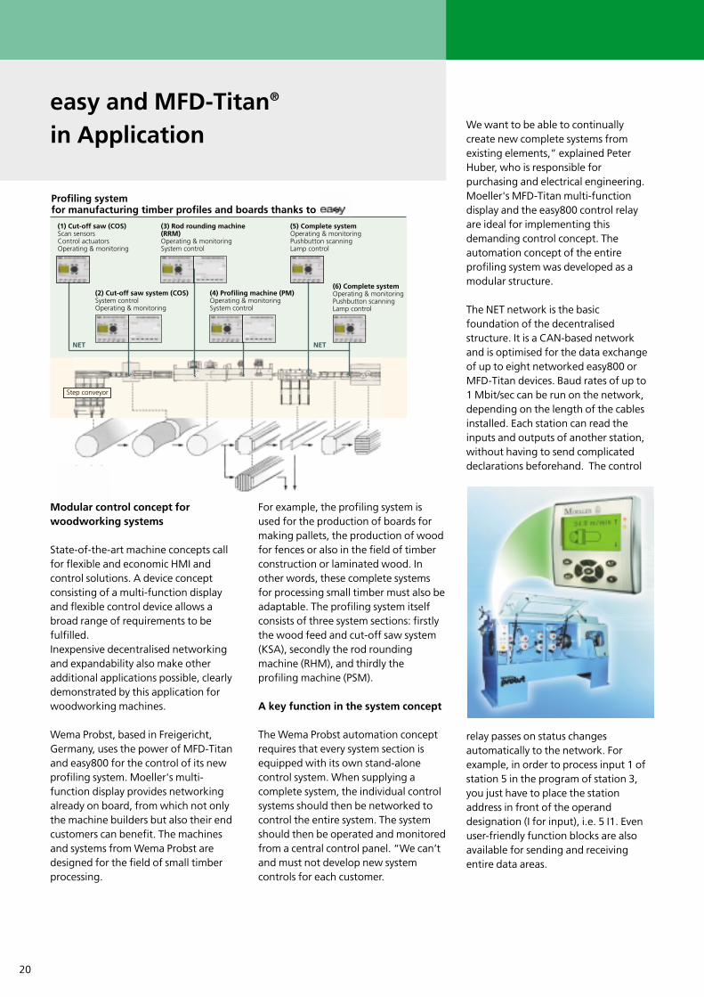
easy and MFD-Titan®
in Application
Profiling system for manufacturing timber profiles and boards thanks to
(1) Cut-off saw (COS)Scan sensorsControl actuatorsOperating & monitoring
NET NET
(2) Cut-off saw system (COS)System controlOperating & monitoring
Step conveyor
(4) Profiling machine (PM)Operating & monitoringSystem control
(3) Rod rounding machine(RRM)Operating & monitoringSystem control
(5) Complete systemOperating & monitoringPushbutton scanningLamp control
(6) Complete systemOperating & monitoringPushbutton scanningLamp control

21
art deco
H1 H2 H3
F1L1
N
S1 S2 S3 S4 S5 S6
ALTDEL
ESC OKeasy 512-AC-RC
I1 I2 I3 I4 I5 I6 I7 I8L N N
Q1 Q2 Q3 Q4
1 2 1 2 1 2 3 2
Task definition
The sales room lighting, shop windowlighting and the outdoor neon sign of ashop have to be switched automatically.This control should process the day ofthe week, the time and the signals froma twilight switch. The switching timesfor the shop window lighting should beadjustable. It must be possible to switchall lights on and off manually. In theevent of an alarm the sales room andshop window lighting should switch on.
Function description
�Outdoor neon sign:(time switch 1)MO-SU 06:00 - 23:00
The outdoor neon sign is affected bythe twilight switch and is switched offat dawn and switched on at dusk. Itmust be possible to switch the neonsign on and off manually at any time.The P2 (Up arrow) and P4 (Down arrow)function buttons on the “easy” are usedfor this purpose.
Note:Use of the P buttons is enabled in theSystem menu. This menu is reached bypressing ALT and DEL simultaneously.Refer to the User Guide AWB 2528-1508.
� Shop window lighting:(time switch 2)MO-FR 08:00 - 22:00 SA 08:00 - 23:00 SU 10:00 - 22:00
The shop window lighting is alsocontrolled by the twilight switch:at dawn it is switched off; at dusk it isswitched on. Pushbutton S5 is to beused to manually switch the shopwindow lighting on and off outside ofthe times set in the program. In theevent of an alarm, the isolated contactS6 of the alarm system should switch onthe shop window lighting. Even if apassword was activated in the Systemmenu, the switching times can bemodified using the enabled time switch2. The time switch is enabled by meansof the “+” symbol in programming.
� Sales room lighting:(time switch 3)MO-FR 08:55 - 13:05
13:55 - 18:35 SA 08:55 - 14:05
The flush-mounted pushbuttons S1, S2,S3 are used to activate the sales roomlighting outside of the times set in theprogram. In the event of an alarm, theisolated contact S6 of the alarm systemshould switch on the sales roomlighting.
Benefits
Implemented functions:3 x time switches, single-channel withweek and day programList price approx. 150 ¤
3 x impulse relaysList price approx. 30 ¤
Less wiring required
Less space required compared to conventional solution
Password function for protectionagainst unauthorised access
The control program is available for downloading from:
http://easy.moeller.net
in the Download area
Programming Example for a Sales Room and Shop Window Lighting
S1-S3 Light switches for sales room lighting
S4 Switch contact for twilight switch
S5 Light switch for shop window lighting
S6 Switch contact for alarm system
H1 Outdoor neon sign
H2 Shop window lighting
H3 Sales room lighting
F1 Miniature circuit-breaker, 16 A, Char. B
22
1 0
F1L1
N
S1S0 S2 S3 Q1 Q2 Q3
ALTDEL
ESC OKeasy 512-AC-R
I1 I2 I3 I4 I5 I6 I7 I8L N N
Q1 Q2 Q3 Q4
1 2 1 2 1 2 1 2
K3K1 K2 H1
L1
NPE
L2L3
Q1
K1
4.43
4.44
Q2
K2
4.43
4.44
Q3
K3
4.43
4.44
M3 ~
M3 ~
M3 ~
M3M2M1
Band 1
Band 3
Band 2
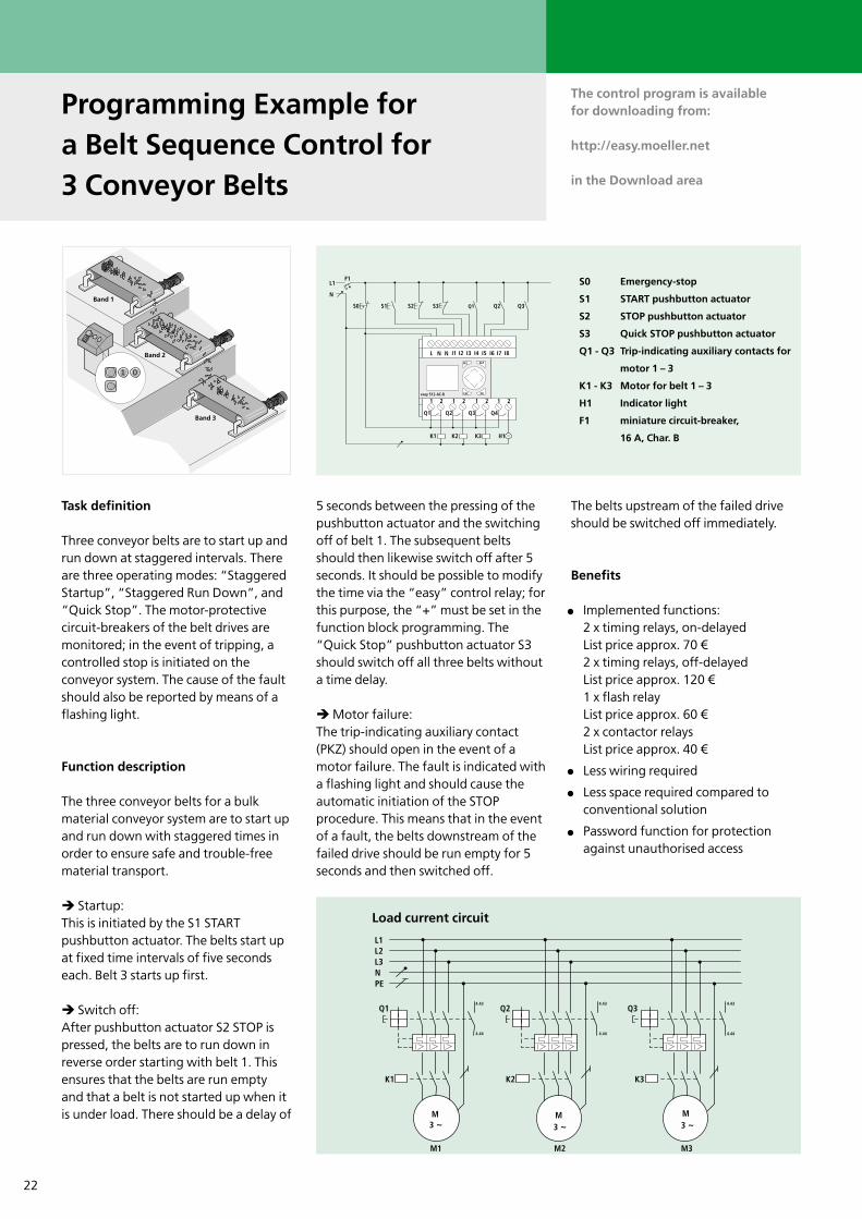
Task definition
Three conveyor belts are to start up andrun down at staggered intervals. Thereare three operating modes: “StaggeredStartup”, “Staggered Run Down”, and“Quick Stop”. The motor-protectivecircuit-breakers of the belt drives aremonitored; in the event of tripping, acontrolled stop is initiated on theconveyor system. The cause of the faultshould also be reported by means of aflashing light.
Function description
The three conveyor belts for a bulkmaterial conveyor system are to start upand run down with staggered times inorder to ensure safe and trouble-freematerial transport.
� Startup:This is initiated by the S1 STARTpushbutton actuator. The belts start upat fixed time intervals of five secondseach. Belt 3 starts up first.
� Switch off:After pushbutton actuator S2 STOP ispressed, the belts are to run down inreverse order starting with belt 1. Thisensures that the belts are run emptyand that a belt is not started up when itis under load. There should be a delay of
5 seconds between the pressing of thepushbutton actuator and the switchingoff of belt 1. The subsequent beltsshould then likewise switch off after 5seconds. It should be possible to modifythe time via the “easy” control relay; forthis purpose, the “+” must be set in thefunction block programming. The“Quick Stop” pushbutton actuator S3should switch off all three belts withouta time delay.
�Motor failure:The trip-indicating auxiliary contact(PKZ) should open in the event of amotor failure. The fault is indicated witha flashing light and should cause theautomatic initiation of the STOPprocedure. This means that in the eventof a fault, the belts downstream of thefailed drive should be run empty for 5seconds and then switched off.
The belts upstream of the failed driveshould be switched off immediately.
Benefits
Implemented functions:2 x timing relays, on-delayedList price approx. 70 ¤2 x timing relays, off-delayedList price approx. 120 ¤1 x flash relayList price approx. 60 ¤2 x contactor relaysList price approx. 40 ¤
Less wiring required
Less space required compared toconventional solution
Password function for protectionagainst unauthorised access
Programming Example for a Belt Sequence Control for 3 Conveyor Belts
The control program is available for downloading from:
http://easy.moeller.net
in the Download area
S0 Emergency-stop
S1 START pushbutton actuator
S2 STOP pushbutton actuator
S3 Quick STOP pushbutton actuator
Q1 - Q3 Trip-indicating auxiliary contacts for
motor 1 – 3
K1 - K3 Motor for belt 1 – 3
H1 Indicator light
F1 miniature circuit-breaker,
16 A, Char. B
Load current circuit
23
H2H1
F1
G1
S00V+24V
L1
PEN
F2
S1 S3S2
K1 K2
~-
Q2Q1B1
P
0-10V
ALTDEL
ESC OKeasy 512-DC-R
I1 I2 I3 I4 I5 I6 I7 I8+24V0V 0V
Q1 Q2 Q3 Q4
1 2 1 2 1 2 1 2
L1
NPE
L2L3
Q1
K1
4.43
4.44
Q2
K2
4.43
4.44
M3 ~
M3 ~
M2M1
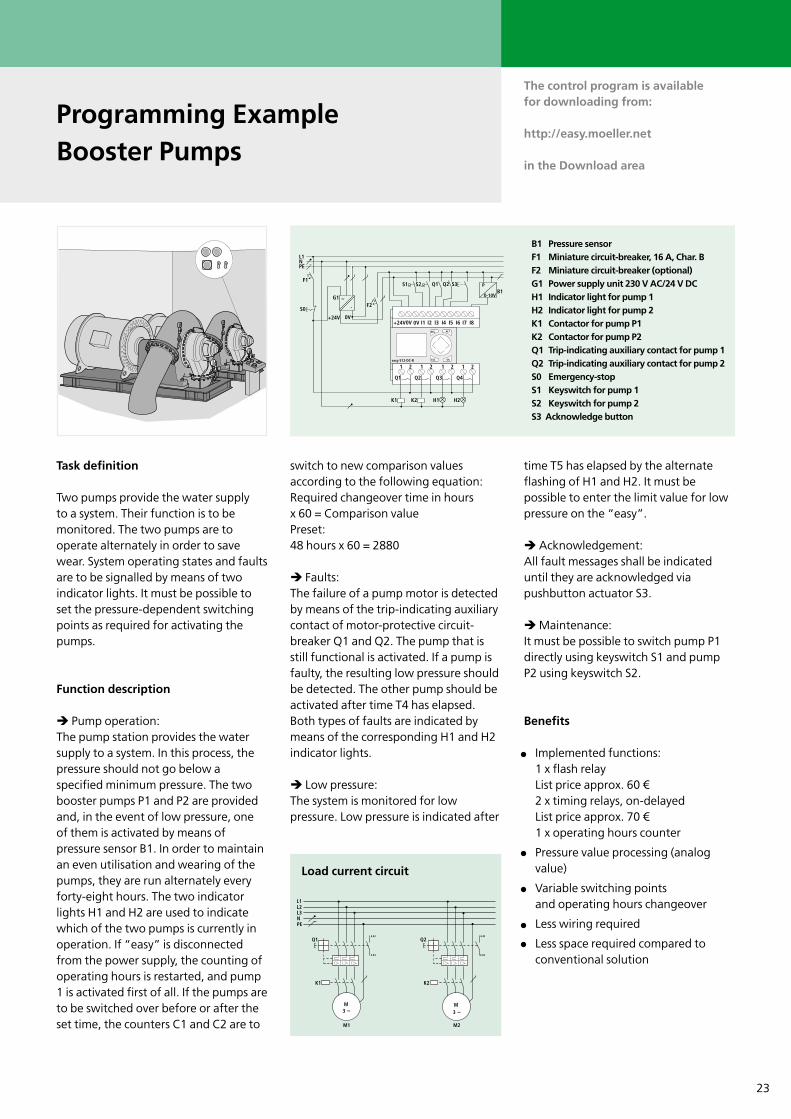
Task definition
Two pumps provide the water supply to a system. Their function is to bemonitored. The two pumps are tooperate alternately in order to savewear. System operating states and faultsare to be signalled by means of twoindicator lights. It must be possible toset the pressure-dependent switchingpoints as required for activating thepumps.
Function description
� Pump operation:The pump station provides the watersupply to a system. In this process, thepressure should not go below aspecified minimum pressure. The twobooster pumps P1 and P2 are providedand, in the event of low pressure, oneof them is activated by means ofpressure sensor B1. In order to maintainan even utilisation and wearing of thepumps, they are run alternately everyforty-eight hours. The two indicatorlights H1 and H2 are used to indicatewhich of the two pumps is currently inoperation. If “easy” is disconnectedfrom the power supply, the counting ofoperating hours is restarted, and pump1 is activated first of all. If the pumps areto be switched over before or after theset time, the counters C1 and C2 are to
switch to new comparison valuesaccording to the following equation:Required changeover time in hoursx 60 = Comparison valuePreset:48 hours x 60 = 2880
� Faults:The failure of a pump motor is detectedby means of the trip-indicating auxiliarycontact of motor-protective circuit-breaker Q1 and Q2. The pump that isstill functional is activated. If a pump isfaulty, the resulting low pressure shouldbe detected. The other pump should beactivated after time T4 has elapsed.Both types of faults are indicated bymeans of the corresponding H1 and H2indicator lights.
� Low pressure:The system is monitored for lowpressure. Low pressure is indicated after
time T5 has elapsed by the alternateflashing of H1 and H2. It must bepossible to enter the limit value for lowpressure on the “easy”.
�Acknowledgement:All fault messages shall be indicateduntil they are acknowledged viapushbutton actuator S3.
�Maintenance:It must be possible to switch pump P1directly using keyswitch S1 and pumpP2 using keyswitch S2.
Benefits
Implemented functions:1 x flash relayList price approx. 60 ¤2 x timing relays, on-delayedList price approx. 70 ¤1 x operating hours counter
Pressure value processing (analogvalue)
Variable switching pointsand operating hours changeover
Less wiring required
Less space required compared toconventional solution
Programming ExampleBooster Pumps
The control program is available for downloading from:
http://easy.moeller.net
in the Download area
B1 Pressure sensorF1 Miniature circuit-breaker, 16 A, Char. BF2 Miniature circuit-breaker (optional)G1 Power supply unit 230 V AC/24 V DCH1 Indicator light for pump 1H2 Indicator light for pump 2K1 Contactor for pump P1K2 Contactor for pump P2Q1 Trip-indicating auxiliary contact for pump 1Q2 Trip-indicating auxiliary contact for pump 2S0 Emergency-stopS1 Keyswitch for pump 1S2 Keyswitch for pump 2S3 Acknowledge button
Load current circuit

Think future. Switch to green.
Xtra Combinations
Xtra Combinations from Moeller offers a range of productsand services, enabling the best possible combination optionsfor switching, protection and control in power distributionand automation.
Using Xtra Combinations enables you to find more efficientsolutions for your tasks while optimising the economic viability of your machines and systems.
It provides:■ flexibility and simplicity■ great system availability■ the highest level of safety
All the products can be easily combined with one another mechanically, electrically and digitally, enabling you to arriveat flexible and stylish solutions tailored to your application –quickly, efficiently and cost-effectively. The products are proven and of such excellent quality thatthey ensure a high level of operational continuity, allowingyou to achieve optimum safety for your personnel, machinery,installations and buildings.
Thanks to our state-of-the-art logistics operation, our com-prehensive dealer network and our highly motivated servicepersonnel in 80 countries around the world, you can count on Moeller and our products every time. Challenge us! We are looking forward to it!
Moeller addresses worldwide:www.moeller.net/addressE-Mail: [email protected]
© 2004 by Moeller GmbHSubject to alterationsW2528-7557GB MDS/DM 04/04 Printed in the Federal Republic of Germany (06/04)Article No.: 284718