distributed by revision 1.3 ke kelit nz technical manual · • ke kelit steelfix stainless steel...
TRANSCRIPT

Revision 1.3
May 2018
VSH XPress GAS
distributed by
KE KELIT NZ
Technical Manual
VSH XPress GAS
distributed by
KE KELIT NZ
Technical Manual
VSH Fittings B.V.
Oude Amersfoortseweg 99
1212 AA Hilversum
Netherlands
Phone: +31 (0) 356 884 330
E-mail: [email protected]
Web: www.vsh.eu
KE KELIT New Zealand Ltd.
12 Gregory Street, Naenae
Lower Hutt 5011
New Zealand
Phone: +64 (4) 568 4870
E-mail: [email protected]
Web: www.kekelit.co.nz
The VSH XPress GAS range distributed by KE KELIT New Zealand are CodeMark certified products.
They are proven to comply with all relevant performance requirements of the New Zealand Building Code.
Please see the inside of the back cover for further details.
– an international company
KE KELIT Kunststoffwerk GmbH, a medium size company in Linz, Austria, has been involved with the
development, production and sales of pipe systems, pipe insulation and pre-insulated pipes for more
than 50 years. From the outset, it was a private initiative of the Karl Egger family.
Success begins with an idea! Over 100 patents and registered designs are clear evidence of the
product development skills at our company.
Quality pipe systems have been manufactured for decades, according to our production techniques,
using the latest production machinery and technology. Since 1994, all the working procedures and
customer relations have been integrated in an ISO 9001 and ISO 14001 certified quality assurance
system.
Our sales in demanding markets worldwide, through our network of subsidiaries and agencies from
Europe to the Middle East and from the Far East to Australia, New Zealand and South America
underline our competitiveness. With over 50 years of experience in the plumbing industry and a
wealth of knowledge, we have become a partner that you can trust to meet your needs. We are happy
to do so both now and to continue to do so in the future.
Our promise is more than just a slogan: Innovative Pipe Systems!
Contents
1 VSH XPress GAS systems ................................................................................................................ 1
2 Technical data .................................................................................................................................... 5
2.1 Areas for using the VSH XPress GAS systems ........................................................................... 5
2.2 VSH XPress GAS pipes ............................................................................................................... 6
2.3 VSH XPress GAS fittings ............................................................................................................. 8
2.4 Press tools ................................................................................................................................. 10
2.5 Installation guidelines ................................................................................................................. 13
2.6 Thermal expansion (in the piping system) ................................................................................. 16
2.7 Pressure drops in gas installations ............................................................................................ 20
2.8 Built-in ........................................................................................................................................ 45
2.9 Corrosion .................................................................................................................................... 47
3. International approvals................................................................................................................... 49
4. Combined press connections ........................................................................................................ 55
5. Product range ................................................................................................................................. 72
5.1 VSH XPress Stainless Steel GAS ............................................................................................. 73
5.2 VSH XPress Copper GAS .......................................................................................................... 84
6. VSH XPress GAS tools and accessories ..................................................................................... 96
Disclaimer:
The technical data are non-binding and not expressly warranted characteristics of the products. These are subject to change. Please consult our General Terms and Conditions of Supply. Additional information is available upon request. It is the Designer’s responsibility to select products suitable for the intended purpose and to ensure that pressure ratings and performance data are not exceeded. Always read and understand the installation instructions. Never remove any piping components nor correct or modify any piping deficiencies without first depressurising and draining the system. This technical handbook is based on European regulations; local regulations must always be adhered to. Product Technical Specification:
Please refer to: VSH XPress GAS distributed by KE KELIT NZ Australasia Technical Specification (Rev 1: March 2018)
© by KE KELIT VSH XPress GAS Handbook 05/2018 English
1
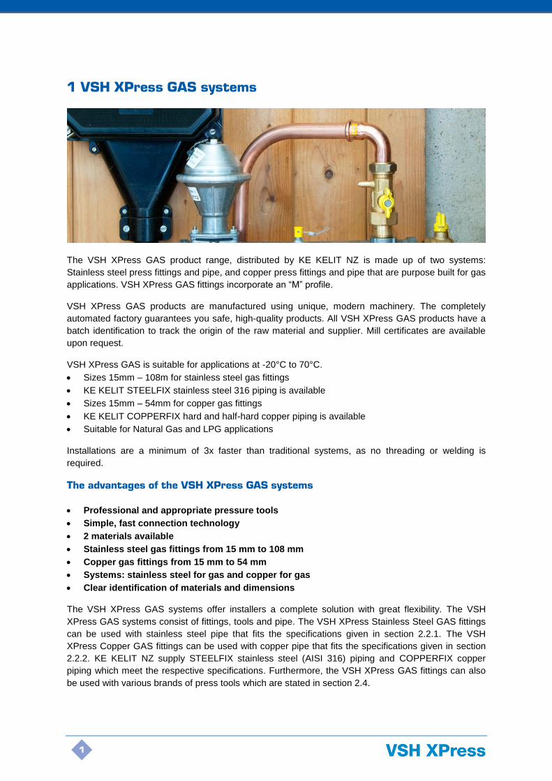
1 VSH XPress GAS systems
The VSH XPress GAS product range, distributed by KE KELIT NZ is made up of two systems:
Stainless steel press fittings and pipe, and copper press fittings and pipe that are purpose built for gas
applications. VSH XPress GAS fittings incorporate an “M” profile.
VSH XPress GAS products are manufactured using unique, modern machinery. The completely
automated factory guarantees you safe, high-quality products. All VSH XPress GAS products have a
batch identification to track the origin of the raw material and supplier. Mill certificates are available
upon request.
VSH XPress GAS is suitable for applications at -20°C to 70°C.
• Sizes 15mm – 108m for stainless steel gas fittings
• KE KELIT STEELFIX stainless steel 316 piping is available
• Sizes 15mm – 54mm for copper gas fittings
• KE KELIT COPPERFIX hard and half-hard copper piping is available
• Suitable for Natural Gas and LPG applications
Installations are a minimum of 3x faster than traditional systems, as no threading or welding is
required.
The advantages of the VSH XPress GAS systems
• Professional and appropriate pressure tools
• Simple, fast connection technology
• 2 materials available
• Stainless steel gas fittings from 15 mm to 108 mm
• Copper gas fittings from 15 mm to 54 mm
• Systems: stainless steel for gas and copper for gas
• Clear identification of materials and dimensions
The VSH XPress GAS systems offer installers a complete solution with great flexibility. The VSH
XPress GAS systems consist of fittings, tools and pipe. The VSH XPress Stainless Steel GAS fittings
can be used with stainless steel pipe that fits the specifications given in section 2.2.1. The VSH
XPress Copper GAS fittings can be used with copper pipe that fits the specifications given in section
2.2.2. KE KELIT NZ supply STEELFIX stainless steel (AISI 316) piping and COPPERFIX copper
piping which meet the respective specifications. Furthermore, the VSH XPress GAS fittings can also
be used with various brands of press tools which are stated in section 2.4.
2
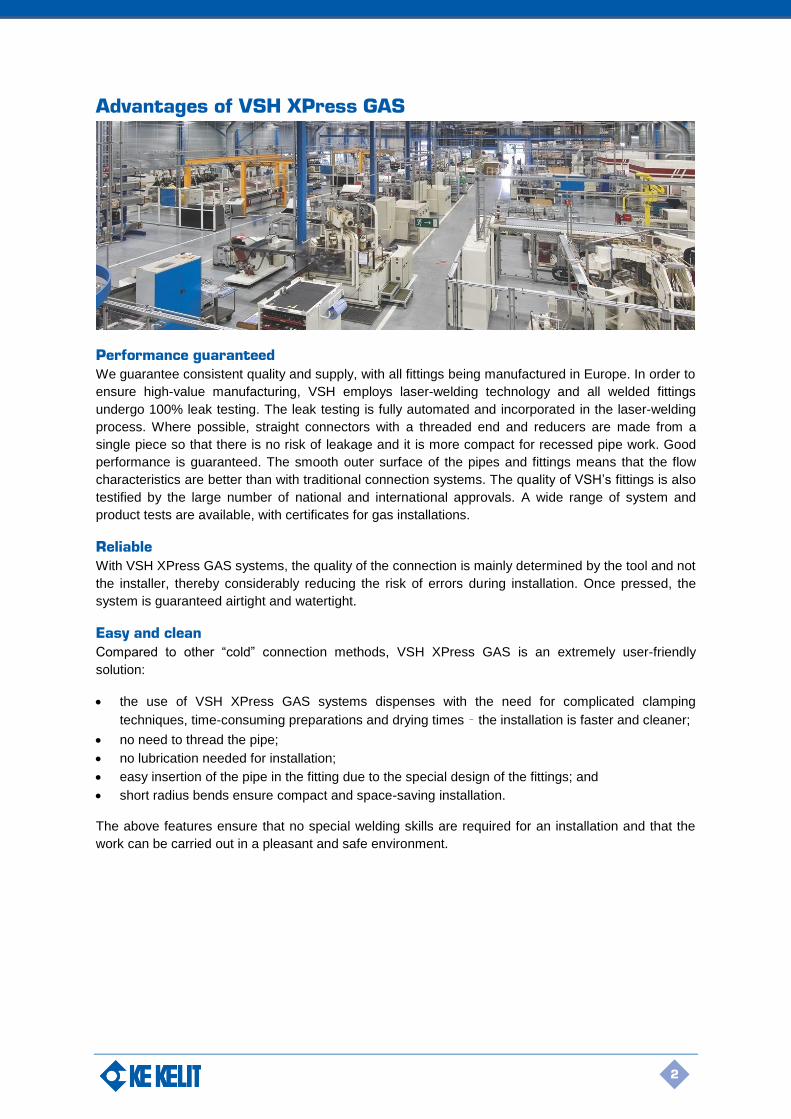
Advantages of VSH XPress GAS
Performance guaranteed
We guarantee consistent quality and supply, with all fittings being manufactured in Europe. In order to
ensure high-value manufacturing, VSH employs laser-welding technology and all welded fittings
undergo 100% leak testing. The leak testing is fully automated and incorporated in the laser-welding
process. Where possible, straight connectors with a threaded end and reducers are made from a
single piece so that there is no risk of leakage and it is more compact for recessed pipe work. Good
performance is guaranteed. The smooth outer surface of the pipes and fittings means that the flow
characteristics are better than with traditional connection systems. The quality of VSH’s fittings is also
testified by the large number of national and international approvals. A wide range of system and
product tests are available, with certificates for gas installations.
Reliable
With VSH XPress GAS systems, the quality of the connection is mainly determined by the tool and not
the installer, thereby considerably reducing the risk of errors during installation. Once pressed, the
system is guaranteed airtight and watertight.
Easy and clean
Compared to other “cold” connection methods, VSH XPress GAS is an extremely user-friendly
solution:
• the use of VSH XPress GAS systems dispenses with the need for complicated clamping
techniques, time-consuming preparations and drying times – the installation is faster and cleaner;
• no need to thread the pipe;
• no lubrication needed for installation;
• easy insertion of the pipe in the fitting due to the special design of the fittings; and
• short radius bends ensure compact and space-saving installation.
The above features ensure that no special welding skills are required for an installation and that the
work can be carried out in a pleasant and safe environment.
3
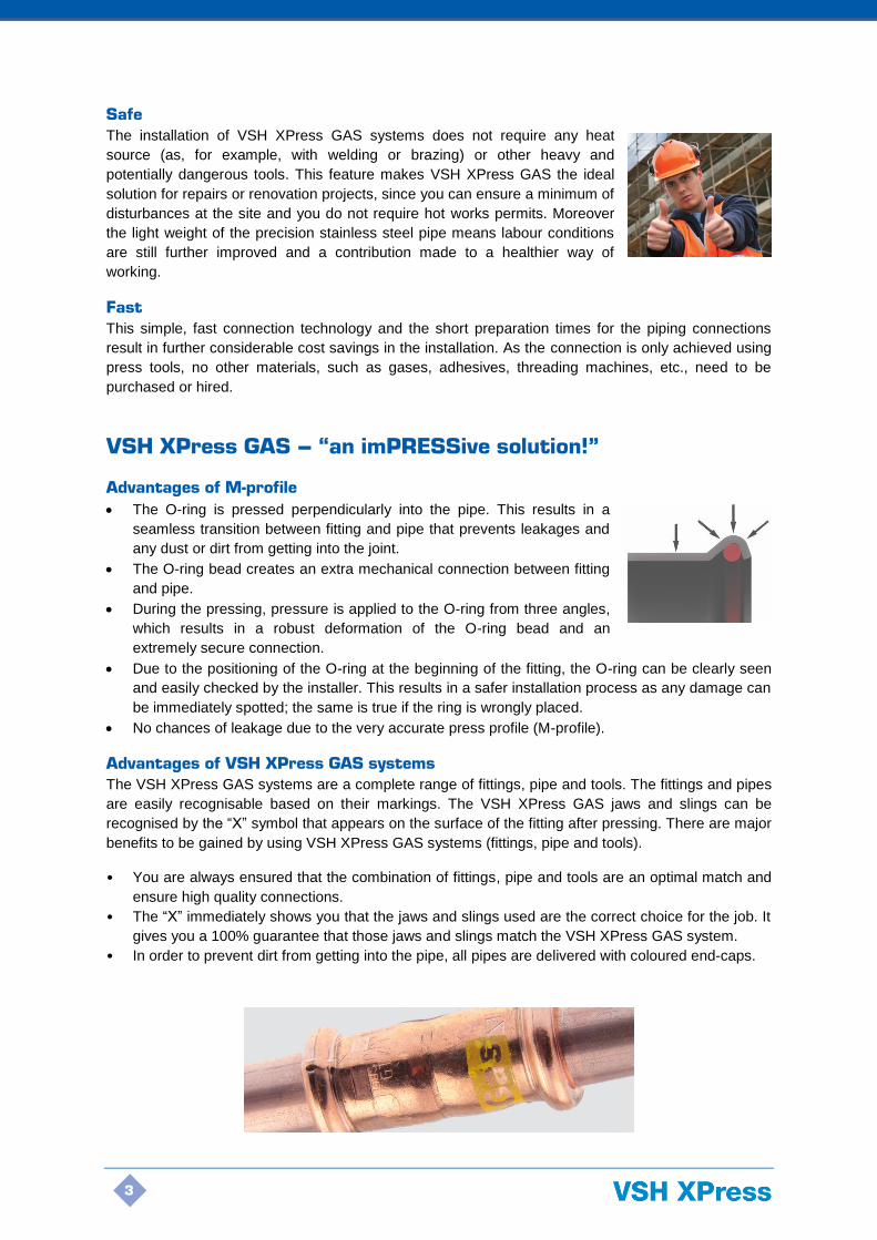
Safe
The installation of VSH XPress GAS systems does not require any heat
source (as, for example, with welding or brazing) or other heavy and
potentially dangerous tools. This feature makes VSH XPress GAS the ideal
solution for repairs or renovation projects, since you can ensure a minimum of
disturbances at the site and you do not require hot works permits. Moreover
the light weight of the precision stainless steel pipe means labour conditions
are still further improved and a contribution made to a healthier way of
working.
Fast
This simple, fast connection technology and the short preparation times for the piping connections
result in further considerable cost savings in the installation. As the connection is only achieved using
press tools, no other materials, such as gases, adhesives, threading machines, etc., need to be
purchased or hired.
VSH XPress GAS – “an imPRESSive solution!”
Advantages of M-profile
• The O-ring is pressed perpendicularly into the pipe. This results in a
seamless transition between fitting and pipe that prevents leakages and
any dust or dirt from getting into the joint.
• The O-ring bead creates an extra mechanical connection between fitting
and pipe.
• During the pressing, pressure is applied to the O-ring from three angles,
which results in a robust deformation of the O-ring bead and an
extremely secure connection.
• Due to the positioning of the O-ring at the beginning of the fitting, the O-ring can be clearly seen
and easily checked by the installer. This results in a safer installation process as any damage can
be immediately spotted; the same is true if the ring is wrongly placed.
• No chances of leakage due to the very accurate press profile (M-profile).
Advantages of VSH XPress GAS systems
The VSH XPress GAS systems are a complete range of fittings, pipe and tools. The fittings and pipes
are easily recognisable based on their markings. The VSH XPress GAS jaws and slings can be
recognised by the “X” symbol that appears on the surface of the fitting after pressing. There are major
benefits to be gained by using VSH XPress GAS systems (fittings, pipe and tools).
• You are always ensured that the combination of fittings, pipe and tools are an optimal match and
ensure high quality connections.
• The “X” immediately shows you that the jaws and slings used are the correct choice for the job. It
gives you a 100% guarantee that those jaws and slings match the VSH XPress GAS system.
• In order to prevent dirt from getting into the pipe, all pipes are delivered with coloured end-caps.
4
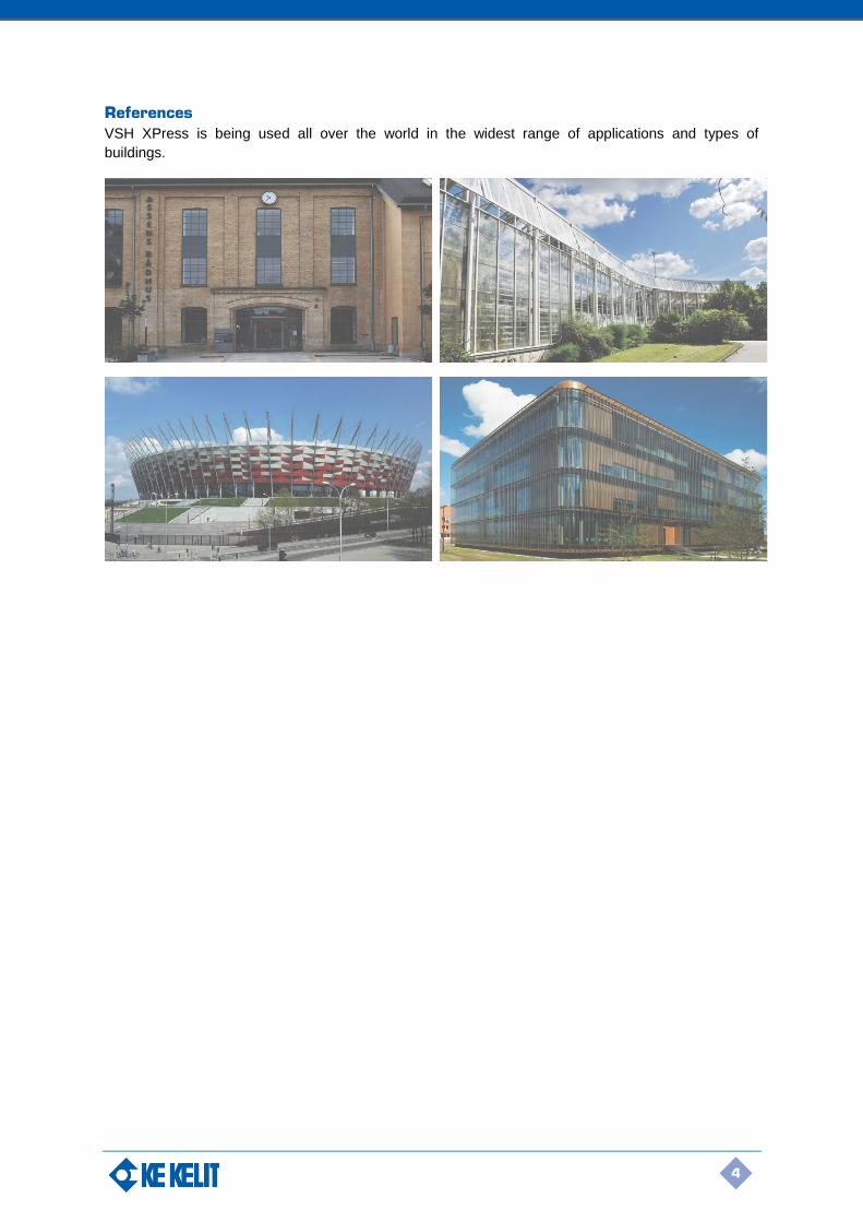
References
VSH XPress is being used all over the world in the widest range of applications and types of
buildings.

5
2 Technical data
2.1 Areas for using the VSH XPress GAS systems
gas
Gas installations
VSH XPress Stainless Steel GAS fittings with stainless steel pipes that satisfy DVGW worksheet
VP614, SVGW Data sheet G1/01 and ÖVGW PG 314.
O-rings: HNBR* (yellow)
Operating temperature: -20°C to +70°C
Operating pressure: Max. 5 bar inside and outside
Application: Inside (HTC**, proven tightness of the connection at 650°C for
30 min) or outside buildings. During construction and in
concrete, above and under screed within buildings, corrosion
protection is recommended (see Section 2.9). Outside of
buildings, only lay above ground. Local regulations must always
be observed.
* Hydrogenated Nitrile Butadiene Rubber
** Higher Thermal Capacity
VSH XPress Copper GAS fittings with copper pipes that satisfy EN1057 R250/R290.
O-rings: NBR*** (yellow)
Operating temperature: -20°C to +70°C
Operating pressure: Max. 5 bar inside and outside
Application: Inside (HTC, proven tightness of the connection at 650°C for 30
min) or outside buildings. During construction and in concrete,
corrosion protection is required (see Section 2.9). Not for
installation below ground, unless in protective ducting. Outside
of buildings, only lay above ground. Local regulations must
always be observed.
***Nitrile Butadiene Rubber
Important:
R220 is NOT approved for gas.
For tools approved for gas installations, see tables 6 and 7 on pages 11-12.

6
2.2 VSH XPress GAS pipes
Pipes used in VSH XPress GAS systems are thin-walled precision pipes. The outer and inner
surfaces of the pipe are blank, free of discoloration and are supplied free of manufacturing residue
that could otherwise cause corrosion. The possibility of any dirt or dust getting into the pipe during
transport or when stored is avoided by caps on both ends of the pipe and correct packaging for
distribution. This section gives you all the relevant technical parameters for suitable piping.
2.2.1 Suitable stainless steel pipes
The stainless steel pipes that may be used for the VSH XPress Stainless Steel GAS system in gas
applications must satisfy DVGW worksheet VP614, SVGW Data sheet G1/01 and ÖVGW PG 314. KE
KELIT NZ supply STEELFIX stainless steel 1.4401 (AISI 316) pipe in the 15-108 mm size range
which is suitable for use with VSH XPress Stainless Steel GAS fittings. These pipes are manufactured
to the specifications of EN 10312 – DVGW – Worksheet GW541 (2004) table 2. STEELFIX stainless
steel (316) pipes have been approved for gas installations inside buildings and outside buildings
above ground (not under screed or underground when outside of buildings).
Fire characteristics
STEELFIX stainless steel (316) pipes are considered as non-combustible pipes according to German
class A building materials – DIN 4102, Part 1.
Applications
The installations must always comply with local regulations.
• Special installations for combustible gases (fittings require special O-rings, see section 2.1):
natural and liquid gases, in accordance with DVGW – Worksheet G260 I/II. Piping for gas or liquid
gas, in accordance with DVGW – Worksheet G600, DVGW – TRGI 86/96 and TRF 1996
Technical characteristics
Material X5CrNiMo 17 12 2 material no. 1.4401 in accordance with DIN-EN 10088
Specifications EN 10312 – DVGW - Worksheet GW541 (2004) table 2
Approvals ÖVGW, DWGW, SVGW, ETA, BYGGFORSK, STF, PZH, SITAC, CST Bat, WRAS, VS, FM, FG, CNBOP, SBSC, SETSCO, LPBC, DNV, GL, RINA, UL, ULc, BV, GDV
Type of pipe TIG or laser-welded
Welding seam 100% EDDY CURRENT tested in accordance with EN 108932:2011
Weld slag removal Outside
Tolerances In accordance with EN10312 - table 2
Finish Annealed under a protective atmosphere W2R
Surface finish Matt silver
Marking steelFlX Edelstahlrohr/stainless steel 1.4401 ø22x1.2 mm OVGW W1.477 TW 110°C/max.16bar EN10312 VdS G411013 [batch number or production date] [supplier code] KE KELIT
Smallest bend radius 3.5 x external diameter of the pipe (max. 28 mm)
Form delivered Pipes, length 6m +0/-50 mm, with protective caps (green)
Heat expansion coefficient
0.0160 mm/m at ΔT= 1K
Max. working pressure
16 bar
Table 1: technical characteristics of STEELFIX stainless steel pipe 1.4401
7
DN Outside ø x s [mm] Inside ø [mm] Weight [kg/m] Tube capacity [L/m]
DN 12 15 x 1.0 13.0 0.333 0.133
DN 15 18 x 1.0 16.0 0.410 0.201
DN 20 22 x 1.2 19.6 0.624 0.302
DN 25 28 x 1.2 25.6 0.790 0.515
DN 32 35 x 1.5 32.0 1.240 0.804
DN 40 42 x 1.5 39.0 1.503 1.195
DN 50 54 x 1.5 51.0 1.972 2.043
DN 65 76.1 x 2.0 72.1 3.550 4.548
DN 80 88.9 x 2.0 84.9 4.150 5.661
DN 100 108 x 2.0 104.0 5.050 8.495
Table 2: dimensions and weight of STEELFIX stainless steel pipe 1.4401
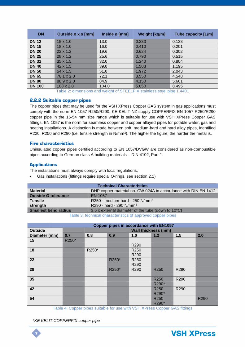
2.2.2 Suitable copper pipes
The copper pipes that may be used for the VSH XPress Copper GAS system in gas applications must
comply with the norm EN 1057 R250/R290. KE KELIT NZ supply COPPERFIX EN 1057 R250/R290
copper pipe in the 15-54 mm size range which is suitable for use with VSH XPress Copper GAS
fittings. EN 1057 is the norm for seamless copper and copper alloyed pipes for potable water, gas and
heating installations. A distinction is made between soft, medium-hard and hard alloy pipes, identified
R220, R250 and R290 (i.e. tensile strength in N/mm2). The higher the figure, the harder the metal is.
Fire characteristics
Uninsulated copper pipes certified according to EN 1057/DVGW are considered as non-combustible
pipes according to German class A building materials – DIN 4102, Part 1.
Applications
The installations must always comply with local regulations.
• Gas installations (fittings require special O-rings, see section 2.1)
Technical Characteristics
Material DHP copper material no. CW 024A in accordance with DIN EN 1412
Outside Ø tolerance EN 1057
Tensile R250 - medium-hard - 250 N/mm2 strength R290 - hard - 290 N/mm2
Smallest bend radius 3.5 x external diameter of the tube (down to 10°C)
Table 3: technical characteristics of approved copper pipes
Copper pipes in accordance with EN1057
Outside Wall thickness (mm)
Diameter (mm) 0.7 0.8 0.9 1.0 1.2 1.5 2.0
15 R250* R290
18 R250*
R250
R290
22 R250* R250 R290
28 R250* R290 R250 R290
35
R250 R290 R290*
42
R250 R290
R290*
54
R250 R290
R290*
Table 4: Copper pipes suitable for use with VSH XPress Copper GAS fittings
*KE KELIT COPPERFIX copper pipe

8
2.3 VSH XPress GAS fittings
2.3.1 Approvals
VSH XPress GAS fittings are tested and approved for gas installations. The approvals held are listed
in the following table:
Approvals VSH XPress Stainless Steel GAS VSH XPress Copper GAS
DVGW 15-108 mm for gas 15-54mm for gas
BSI 15-108 mm for gas 15-54mm for gas
ÖVGW 15-108 mm for gas 15-54mm for gas
SVGW 15-108 mm for gas -
Table 5: Approvals
2.3.2 Technical characteristics
VSH XPress Stainless Steel GAS fittings are produced from 1.4404 materials, in accordance with DIN
10088 and are fitted with a “yellow” HNBR O-ring.
VSH XPress Copper GAS fittings are produced from CU-DHP copper, CW024A materials and 2.109
bronze materials and are fitted with a “yellow” NBR O-ring.
The sizes 15-108 mm of VSH XPress Stainless Steel GAS for gas installations must be pressed using
Novopress or Klauke jaws/press slings. The sizes 76.1-108 mm VSH XPress Stainless Steel GAS
fittings must be pressed using a Novopress ECO301, ACO401 or Klauke UAP100(L). The sizes 15-
54mm for VSH XPress Copper GAS for gas installations can be pressed using Novopress, Klauke
Rems or Roller jaws/press slings. Press tools, jaws and slings of other suppliers may be authorised
under local approvals.
Threaded fittings
The VSH XPress GAS product range includes components with inner and outer threads. VSH XPress
GAS fittings with inner and outer threads are manufactured in accordance with DIN 2999/ISO 7/1.
Hemp or other chloride-free sealants are suitable for the threads of VSH XPress Stainless Steel GAS
fittings. PTFE sealing tape may not be used in conjunction with stainless steel due to the water
soluble chloride ions it contains.With threaded couplings, we recommend that the sealing be executed
before the pressing, in order not to stress the press connection.
Screw fittings (copper)
The manufacturers of gas heating appliances supply their products with the respective screw
connections in place. G6360-type “half screw fittings” may, therefore, be used as press connections to
already-present screw connections. The half screw fitting (G6360), as well as the G6340 screw fitting
with a double-sided press end, is also approved in accordance with DIN 3436 HTC.
Bronze threaded transition fittings.
Threaded transition fittings are generally manufactured from gun metal. A distinction is made in this
case between strand or continuous casting (straight joints) and mould casting (bends, T-pieces and
wall plates). Tests have shown that mould cast (sand cast) press fittings are less suitable for gas
applications for the following reasons: mould casting joints can never be as leak-proof (homogenous)
as strand cast or copper ones. There is always, in particular, a danger of air cavities despite 100%
impermeability testing. Additionally, the mechanical load of the pressing heightens these dangers as it
may cause cavities to burst open. Therefore, for safety reasons, no mould-cast parts are included in
the VSH XPress Copper GAS press fitting range.

9
VSH XPress Stainless Steel GAS fitting markings
VSH XPress Stainless Steel GAS fittings
Marking Packaging label
Yellow marking Type R…..G GAS, GT5/MOP5 Dimension 316L Description XPress EAN No. Dimension Art. no. DVGW Approvals Quantity
VSH XPress Copper GAS fitting markings
VSH XPress Copper GAS fittings
Marking Packaging label
Yellow marking Type G….. GAS, GT1/MOP5 Dimension RYW Description Dimension EAN No. DVGW Art. no. Gastec Qa Approvals Quantity
O-rings
The type of O-ring which has to be used depends on the application and the medium. That is why
VSH XPress GAS press fittings are fitted with (H)NBR O-rings. If your application is not listed in the
tables below, please contact KE KELIT NZ to find out whether the medium is suitable for use in
combination with the type of press fitting you are using.
Important:
O-rings used for gas applications DO NOT have a leak before pressed function for safety
reasons.
Hydrogenated Nitrile Butadiene Rubber (HNBR) for VSH XPress Stainless Steel GAS - yellow
Temperature Applications
-20°C to +70°C Installations for combustible gases: natural gases and liquid gases in accordance with Worksheet DVGW G260 I/II. Installations for natural gas in accordance with Worksheet DVGW G600 TRGI 86/96, and liquid gases in accordance with TRF(1996)
Nitrile Butadiene Rubber (NBR) for VSH XPress Copper GAS - yellow
Temperature Applications
-20°C to +70°C Installations for combustible gases: natural gases and liquid gases in accordance with Worksheet DVGW Gas TRGI 86/89, and for liquid gases in accordance with TRF(1996)
2.3.3 Alternative VSH XPress applications
The choice of fittings and pipes depends on what the purpose of the system is, the medium and the
operating conditions. Please contact KE KELIT NZ regarding approval for any applications other than
natural gas or LPG. Installations must always comply with local regulations.
10
2.3.4 (Main) Equipotential bonding in residential premises
All metal tubing systems using equipotential bonding must comply with equipotential bonding
requirements. Continuity checks must be conducted by a qualified electrician in accordance with the
regulations, once the installation work has been finished. STEELFIX stainless steel (316) pipes and
COPPERFIX copper pipes used in combination with the respective VSH XPress GAS fittings are
electrically conductive pipe systems and, therefore, must be included in the equipotential bonding.
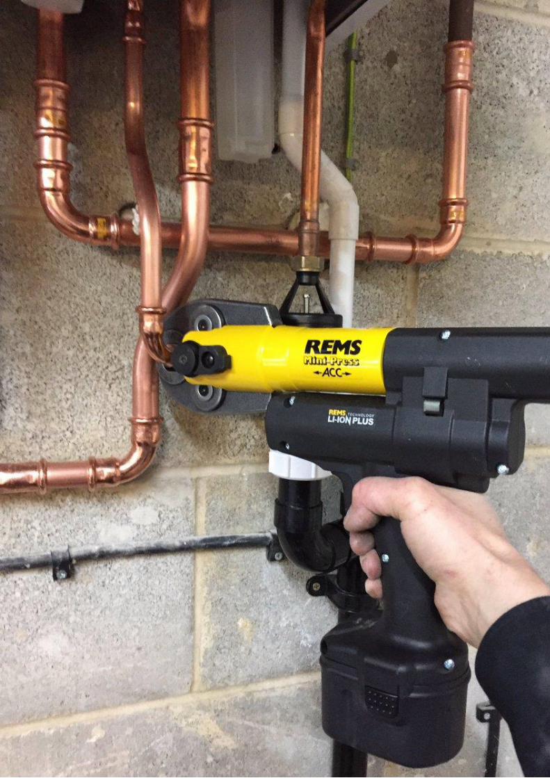
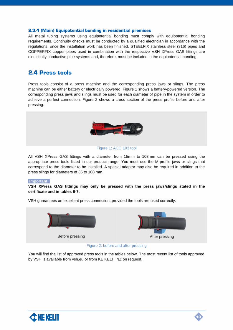
2.4 Press tools
Press tools consist of a press machine and the corresponding press jaws or slings. The press
machine can be either battery or electrically powered. Figure 1 shows a battery-powered version. The
corresponding press jaws and slings must be used for each diameter of pipe in the system in order to
achieve a perfect connection. Figure 2 shows a cross section of the press profile before and after
pressing.
Figure 1: ACO 103 tool
All VSH XPress GAS fittings with a diameter from 15mm to 108mm can be pressed using the
appropriate press tools listed in our product range. You must use the M-profile jaws or slings that
correspond to the diameter to be installed. A special adaptor may also be required in addition to the
press slings for diameters of 35 to 108 mm.
Important:
VSH XPress GAS fittings may only be pressed with the press jaws/slings stated in the
certificate and in tables 6-7.
VSH guarantees an excellent press connection, provided the tools are used correctly.
Before pressing
After pressing
Figure 2: before and after pressing
You will find the list of approved press tools in the tables below. The most recent list of tools approved
by VSH is available from vsh.eu or from KE KELIT NZ on request.

11
2.4.1 Press tools approved for VSH XPress Stainless Steel GAS
Dimension Manufacturer Press tool Press jaws/slings
15-28 mm Novopress Presskid (12V) AFP101 (9.6V) ACO102/103 (12V)
Presskid jaws: 15-28 mm PB1 jaws: 15-28 mm (AFP 101/ACO102)
15-54 mm Novopress ECO1 Pressboy (230V) ECO201/202/203 (230V) ACO1 Pressboy (12V) ACO201 (12V) ACO202/ACO203 (18V) EFP2/201/202 (230V) AFP201/202 (14.4V)
PB2 ECOTEC jaws: 15-35 mm Slings and adapter 42-54 mm: (Snap-on) slings 42 and 54 (with adapter ZB201/ZB203)
15-108 mm Novopress ECO 3 Pressmax (230V) ECO301 (230V) ACO3 Pressmax (12V)
Jaws ACO3/ECO3/ECO301: 15-54 mm Slings and adapter 42-54 mm: Slings 42 and 54 (with adapter ZB302/ ZB303) Snap-on slings 42, and 54 (with adapter ZB303) Slings and adapter (76.1-108mm): Slings 76.1-88.9 mm (1 adapter ZB321/ZB323) Snap-on slings 76.1-88.9 mm (1 adapter ZB323) Slings 108 (2 adapters mandatory ZB321 & ZB322 or ZB323 & ZB324) Snap-on slings 108 (2 adapters mandatory ZB323 & ZB324) Important: press 108mm in 2 stages!
15-108 mm Novopress ACO203XL (18V) PB2 ECOTEC jaws: 15-35 mm (Snap-on) slings and adapter ZB201/ZB203: 42-54 mm Snap-on slings in combination with ZB221: 76.1-88.9 Snap-on sling 108 with adapters ZB221 & ZB222 Important: press 108mm in 2 stages!
15-22 mm Klauke MAP1 `Klauke Mini' (9.6V) MAP2L `Klauke Mini' (18V)
Klauke Mini jaws: 15-22 mm (KSP3)
15-54 mm Klauke UAP2/UP75 (12V) UNP2 (230V) UAP3L (18V) UAP4 (12V) UAP4L (18V)
Important: only with Novopress or Klauke jaws and slings (KSP3), 15-28 mm, SB35MS for 35 mm, and slings 42 and 54 mm with adapter (SBK4254)
15-54 mm Rems Powerpress (230V) Powerpress ACC (230V) Battery-Press (12V) Battery-Press ACC (12V)
Important: only with Novopress jaws and slings
15-54 mm Virax Viper P20 (14.4V) Viper P21 (18V)
Important: only with Novopress jaws and slings
15-28 mm Rothenberger Romax Compact (12V) Important: only with Novopress jaws and slings
15-54 mm Rothenberger Romax-Pressliner (12V) Romax-Pressliner ECO (12V) Romax AC Eco (230V) Romax 3000 (18V)
Important: only with Novopress jaws and slings
Table 6: press jaws are not permitted from Ø42 mm
12
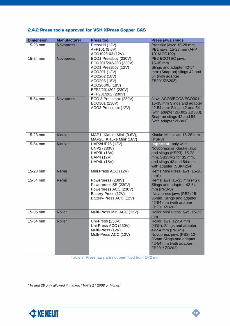
2.4.2 Press tools approved for VSH XPress Copper GAS
Dimension Manufacturer Press tool Press jaws/slings
15-28 mm Novopress Presskid (12V) AFP101 (9.6V) ACO102/103 (12V)
Presskid jaws: 15-28 mm, PB1 jaws: 15-28 mm (AFP 101/ACO102)
15-54 mm Novopress ECO1 Pressboy (230V) ECO201/202/203 (230V) ACO1 Pressboy (12V) ACO201 (12V) ACO202 (18V) ACO203 (18V) ACO203XL (18V) EFP2/201/202 (230V) AFP201/202 (230V)
PB2 ECOTEC jaws: 15-35 mm Slings and adapter 42-54 mm: (Snap-on) slings 42 and 54 (with adapter ZB201/ZB203)
15-54 mm Novopress ECO 3 Pressmax (230V) ECO301 (230V) ACO3 Pressmax (12V)
Jaws ACO3/ECO3/ECO301: 15-35 mm Slings and adapter 42-54 mm: Slings 42 and 54 (with adapter ZB302/ ZB303), Snap-on slings 42 and 54 (with adapter ZB303)
15-28 mm Klauke MAP1 `Klauke Mini' (9.6V), MAP2L `Klauke Mini' (18V)
Klauke Mini jaws: 15-28 mm (KSP3)
15-54 mm Klauke UAP2/UP75 (12V) UNP2 (230V) UAP3L (18V) UAP4 (12V) UAP4L (18V)
Important: only with Novopress or Klauke jaws and slings (KSP3), 15-28 mm, SB35MS for 35 mm, and slings 42 and 54 mm with adapter (SBK4254)
15-28 mm Rems Mini Press ACC (12V) Rems Mini Press jaws: 15-28 mm*)
15-54 mm Rems Powerpress (230V) Powerpress SE (230V) Powerpress ACC (230V) Battery-Press (12V) Battery-Press ACC (12V)
Rems jaws: 15-35 mm (4G), Slings and adapter: 42-54 mm (PR3-S) Novopress jaws (PB2) 15-35mm, Slings and adapter: 42-54 mm (with adapter ZB201 /ZB203)
15-35 mm Roller Multi-Press Mini ACC (12V) Roller Mini Press jaws: 15-35 mm
15-54 mm Roller Uni-Press (230V) Uni-Press ACC (230V) Multi-Press (12V) Multi-Press ACC (12V)
Roller jaws: 12-54 mm (4G)*), Slings and adapter: 42-54 mm (PR3-S) Novopress jaws (PB2) 12-35mm Slings and adapter: 42-54 mm (with adapter ZB201/ ZB203)
Table 7: Press jaws are not permitted from Ø42 mm
*18 and 28 only allowed if marked “108” (Q1 2008 or higher)

13
2.4.3 Maintenance and correct usage of press tools
Correct pressing with the VSH XPress GAS systems is guaranteed when the press tools listed in
tables 6 and 7 are used correctly. Regular maintenance and lubrication of the press jaws, slings and
tools is necessary. Please observe the manufacturer's instructions for use and maintenance. When
jointing VSH XPress Copper GAS fittings larger than 35mm, it is essential that the grooves in the
press jaw/sling be lubricated with Dri-slide lubricant! The jaws/ slings should be lubricated in this way
after every 50 joints for sizes 42 mm to 54 mm. Note that care must be taken to avoid any contact
between lubricant and 'O-rings'. Badly maintained and/ or damaged press jaws pose a potential risk.
Damaged jaws can damage the fittings, leaving metal particles behind in the jaw as a result. If the
same jaw is then used to press a stainless steel fitting, these metal particles will be pressed into the
fitting, which could lead to pitting and further corrosion. Therefore always make sure that press jaws
and slings are properly cleaned when switching between materials. Other press tools not mentioned
in the sections 2.4.1 and 2.4.2 may be approved upon request.
2.5 Installation guidelines
2.5.1 Cut the pipe to length
After measuring, pipes can be cut to length using a pipe cutter (see fig.
3), a fine-toothed handsaw or a mechanical saw with electrical motor
suitable for the pipe material. The pipe must always be cut completely
through. Never partially cut the pipe and break it off as this could cause
corrosion.
Do not use oil-cooled saws, grinding wheels or flame cutters.
2.5.2 Deburring the pipe
The pipe ends must be carefully and thoroughly deburred inside and
out after being cut to length. This is in order to avoid any damage to
the O-ring when inserting the pipe into the press fitting. Deburring the
inside of pipes prevents pitting and corrosion. A hand deburrer suitable
for the material or an electrical pipe deburrer may be used to deburr
both the inside and outside of the pipe. Burrs sticking to the pipe must
be removed.
2.5.3 Calibration
Always ensure the pipe ends are radial and evenly rounded-off. The pipe ends must be calibrated
before pressing.
2.5.4 Marking insertion depth
The required insertion depth (see table 8A) must be marked on the
pipe or the press fitting (the latter for fitting with pipe ends) in order to
guarantee a safe and proper joint. Mark the insertion depth using the
insertion depth marker for VSH XPress GAS. Reliable pressing with
the corresponding tensile strengths can only be achieved if the
elements are correctly installed. The pressing operation behind the
bead is of crucial importance for the tensile strength.
The marking on the pipe must remain visible (but close to the fitting)
after the connection is pressed to identify any movement before or
after pressing.
Figure 4: deburring the pipe
Figure 3: cutting the pipe
Figure 5: marking insertion depth

14
2.5.5 Check the fitting and pipe
Before assembly, the fitting must be checked to ensure that the
O-rings are present and correctly positioned. The pipe, fitting and
O-ring must be examined for any foreign materials (e.g. dirt, burrs),
which must be removed, if present.
2.5.6 Assembly of fitting and pipe
Insert the pipe carefully into the press fitting up to the marked
insertion depth, simultaneously rotating and pushing it in the
direction of the axis. The insertion depth marking must remain
visible. In the case of fittings without a stop the fittings should be
inserted as far as the marked insertion depth. Rough and careless
insertion of the pipe into the press fitting may result in damage to
the O-ring and therefore is not permitted.
If assembly is difficult because of the permitted tolerances in size, a lubricant,
such as water or soap, may be used. Under no circumstances may oils, fats
or grease be used as lubricants. To optimise the installation time, time may be
saved by first assembling a number of connections and then pressing the
various pipe connections one after the other. Marking the distance (A) provides
a check that the pipe has not been pushed out of the fitting during the pressing
process. Before starting the final pressing process of the various pipe
connections, it is also important to check the minimum required distances for the
installation (see table 8A).
Insertion Depth Minimum Distance Minimum tube length
Ø [mm] A (mm) dmin (mm) 2xA + dmin (mm)
VSH XPress Stainless Steel GAS
VSH XPress Copper GAS
VSH XPress Stainless Steel GAS & VSH XPress Copper GAS
VSH XPress Stainless Steel GAS
VSH XPress Copper GAS
15 20 20 10 50 50
18 20 20 10 50 50
22 21 21 10 52 52
28 23 23 10 56 56
35 26 26 10 62 62
42 30 30 20 80 80
54 35 35 20 90 90
76.1 55 - 55 165 -
88.9 63 - 65 186 -
108 77 - 80 234 -
Table 8A: minimum distances between pressings
Table 8B below gives the minimum required working space so that the pressing of the fittings can be
carried out correctly using the appropriate press tools. These distances relate to the general
installation configurations that are schematically depicted in figures 9-11.
Figure 6: checking fitting/pipe
Figure 7: assembling fitting and pipe
Figure 8

15
Outside-Ø
Fig. 9 Fig. 10 Fig. 11
a b a b c d Pipe depth
15 mm 56 20 75 25 28 131 40 mm
18 mm 60 20 75 25 28 131 40 mm
22 mm 65 25 80 31 35 150 40 mm
28 mm 75 25 80 31 35 150 60 mm
35 mm 75 30 80 31 44 170 70 mm
42 mm 140/115* 60/75* 140/115* 60/75* 75 265 70 mm
54 mm 140/120* 60/85* 140/120* 60/85* 85 290 70 mm
76.1 mm 140* 110* 165* 115* 115 395 80 mm
88.9 mm 150* 120* 185* 125* 125 435 90 mm
108 mm 170* 140* 200* 135* 135 470 100 mm
Table 8B: space needed for installation (*slings)
2.5.7 Pressing
Before starting to press, the press jaws and slings must be checked for dirt, which must be removed if
present. Furthermore, the press machine must be in good condition and the instructions for operating
the device, maintenance and the manufacturer's instructions must be observed. Make sure that you
are using the correct press jaws and slings. In order to create a correctly pressed connection, the
groove of the press tool must enclose the press fitting O-ring bead. Once the pressing has started,
always complete the press cycle and under no circumstances interrupt the process. The approved
machine, press jaws and press slings are shown in Tables 6 and 7 on pages 11-12.
Important:
It is not permitted to press a connection more than once.
Figure 10 Figure 9 Figure 11

16
Pressing gas installations
The VSH XPress Stainless Steel GAS and VSH XPress Copper GAS systems are suitable for gases
of the second and the third gas family (natural and liquid gases) in accordance with DVGW Worksheet
G 260 and are installed inside buildings and above ground outside buildings.
A combination of VSH XPress Copper GAS and VSH XPress Stainless Steel GAS systems is not
permitted for new installations. Connections to gas fittings and gas parts in brass, bronze, ductile grey
cast iron and die cast aluminium may be connected with gas thread/press fittings or flanges. If
renovations or repairs are being carried out, make sure the pipes are in accordance with the DIN-
EN/DVGW standards, have perfect, undamaged outer surfaces and have not been painted. VSH
XPress Copper GAS has been certified by Gastec QA and by KVGB (Ø15 – 28mm). VSH XPress
Copper GAS fittings are NOT allowed to be used in combination with soft copper pipe EN1057 R220.
Local regulations must always be observed (e.g. NZS 5261:2003 and AS/NZS 5601.1:2013):
1. Gas pipes and fittings must be marked yellow to avoid confusion.
2. Pipes must be protected during construction against mechanical damage.
3. Carry out tests according to Appendix E of AS/NZS 5601.1:2013.
4. When laid under screed (above the reinforcement), place in concrete slots.
5. Operating temperature: -20°C to +70°C
2.5.8 Bending pipes
It may be necessary to bend a pipe in order to carry out the installation. Normal hand, hydraulic or
electrically-operated pipe benders with the corresponding bend formers can be used for this. The
manufacturer will determine the suitability of the bending tool. Approved stainless steel pipes and
copper pipes may be bent cold, in accordance with DIN EN 1057.
Important:
The pipe may not be bent went warm due to the danger of corrosion
The smallest bending radius is as follows:
Stainless steel pipes (15 - 28 mm) rmin = 3.5 x d
Copper pipes (15 - 54 mm) rmin = 3.5 x d
A smaller bend radius is not permitted.
2.6 Thermal expansion (in the piping system)
The level of thermal expansion within piping systems depends on the type of materials used. This
linear expansion needs to be taken into account during the installation. Small changes in length can
be accommodated by having adequate space for expansion as well as by the elastic properties of the
tubing system itself. More substantial changes in length need to be offset by other means; e.g.
installation of special expansion compensation devices, fixed anchoring points and brackets.
Expansion can be offset by the use of a pipe segment (figure 12, 13), U-bend (figure 14) or
compensators. The level of expansion to be offset can be determined beforehand by calculating the
changes in length.

17
The equation for calculating the changes in length is as follows:
Δl = total linear expansion [mm] l = length of segment in question [m] ΔT = temperature difference [K] α = linear expansion coefficient, where: for STEELFIX stainless steel pipe 1.4401 α = 0.0160 mm/mK for copper pipe α = 0.0170 mm/mK Tables 9A and 9B show the expansion of the pipeline depending on the length of the pipe and the rise in temperature.
l [m] ΔT [K]
10 20 30 40 50 60 70 80 90 100
1 0.16 0.32 0.48 0.64 0.80 0.96 1.12 1.28 1.44 1.60
2 0.32 0.64 0.96 1.28 1.60 1.92 2.24 2.56 2.88 3.20
3 0.48 0.96 1.44 1.92 2.40 2.88 3.36 3.84 4.32 4.80
4 0.64 1.28 1.92 2.56 3.20 3.84 4.48 5.12 5.76 6.40
5 0.80 1.60 2.40 3.20 4.00 4.80 5.60 6.40 7.20 8.00
6 0.96 1.92 2.88 3.84 4.80 5.76 6.72 7.68 8.64 9.60
7 1.12 2.24 3.36 4.48 5.60 6.72 7.84 8.96 10.08 11.20
8 1.28 2.56 3.84 5.12 6.40 7.68 8.96 10.24 11.52 12.80
9 1.44 2.88 4.32 5.76 7.20 8.64 10.08 11.52 12.96 14.40
10 1.60 3.20 4.80 6.40 8.00 9.60 11.20 12.80 14.40 16.00
12 1.92 3.84 5.76 7.68 9.60 11.52 13.44 15.36 17.28 19.20
14 2.24 4.48 6.72 8.96 11.20 13.44 15.68 17.92 20.16 22.40
16 2.56 5.12 7.68 10.24 12.80 15.36 17.92 20.48 23.04 25.60
18 2.88 5.76 8.64 11.52 14.40 17.28 20.16 23.04 25.92 28.80
20 3.20 6.40 9.60 12.80 16.00 19.20 22.40 25.60 28.80 32.00
Table 9A: linear expansion Δl [mm]. Only for stainless steel 1.4401
l [m] ΔT [K]
10 20 30 40 50 60 70 80 90 100
1 0.17 0.34 0.51 0.68 0.85 1.02 1.19 1.36 1.53 1.70
2 0.34 0.68 1.02 1.36 1.70 2.04 2.38 2.72 3.06 3.40
3 0.51 1.02 1.53 2.04 2.55 3.06 3.57 4.08 4.59 5.10
4 0.68 1.36 2.04 2.72 3.40 4.08 4.76 5.44 6.12 6.80
5 0.85 1.70 2.55 3.40 4.25 5.10 5.95 6.80 7.65 8.50
6 1.02 2.04 3.06 4.08 5.10 6.12 7.14 8.16 9.18 10.20
7 1.19 2.38 3.57 4.76 5.95 7.14 8.33 9.52 10.71 11.90
8 1.36 2.72 4.08 5.44 6.80 8.16 9.52 10.88 12.24 13.60
9 1.53 3.06 4.59 6.12 7.65 9.18 10.71 12.24 13.77 15.30
10 1.70 3.40 5.10 6.80 8.50 10.20 11.90 13.60 15.30 17.00
12 2.04 4.08 6.12 8.16 10.20 12.24 14.28 16.32 18.36 20.40
14 2.38 4.76 7.14 9.52 11.90 14.28 16.66 19.04 21.42 23.80
16 2.72 5.44 8.16 10.88 13.60 16.32 19.04 21.76 24.48 27.20
18 3.06 6.12 9.18 12.24 15.30 18.36 21.42 24.48 27.54 30.60
20 3.40 6.80 10.20 13.60 17.00 20.40 23.80 27.20 30.60 34.00
Table 9B: total linear expansion Δl [mm]. Only for copper.
Δl = l x α x ΔT
18
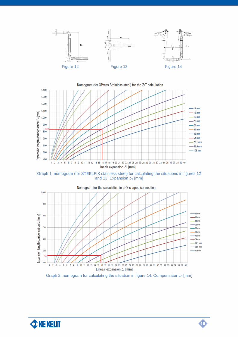
Figure 12 Figure 13 Figure 14
Graph 1: nomogram (for STEELFIX stainless steel) for calculating the situations in figures 12 and 13. Expansion bd [mm]
Graph 2: nomogram for calculating the situation in figure 14. Compensator Lb [mm]

19
Calculation of the expansion length to be allowed for:
In the case of major expansion, expansion compensators or, in complicated cases, Ω-shaped
compensation loops will need to be determined and fitted. The compensation (in mm) can be
calculated for different situations with the following formulas:
Figure 12:
Figure 13:
Figure 14:
Bd = expansion compensator length (figures 12 and 13)
Lb = depth of Ω-shaped expansion compensator (figure 14)
k = material constant
= 45 for STEELFIX stainless steel (316) pipes
= 35 for COPPERFIX copper pipes
de = external diameter of the pipe [mm]
Δl = linear expansion that needs to be compensated [mm]
The nomogram in graph 1 enables the expansion bend length [Bd] for figure 12 to be rapidly and
accurately determined by taking account of the respective pipe types and the expansion to be
compensated [Δl]. For the situation in figure 13, multiply the Bd value from graph 1 by 1.44 to
determine the expansion compensation length. Graph 2 gives the Lb values for the installation
situation illustrated in figure 14.
The following is an example of an analytical calculation: A pipe network with a length of 16 m
consisting of STEELFIX stainless steel 1.4401 piping with a diameter of 22 mm is subject to a
temperature difference of 60 K. If we use the equation for calculating the expansion, the result is:
We would get the same result from the data in table 9A without having to perform the calculation. In
addition to the expansion for the respective section of the pipeline, we need to calculate the length of
the expansion compensator required for its compensation – see figure 12. Using the nomogram in
graph 1, we obtain approx. 830mm. The analytical calculation gives the following result:
In the case of an Ω-shaped expansion connection, the calculated value of an expansion equalizer [Lb]
as in figure 14 has to be approximately halved as it is effectively two expansion sections. The value
[Bd] does not have to be divided exactly by two, but should be divided by a factor of 1.8:
Bd = 1.44 x k x √(de x Δl)
Δl = 16 x 0.0160 x 60 = 15.36 mm
Bd = 45 x √22 x 15.36 = 827.2 mm
Lb= Bd
1.8=
827.2
1.8 = 459.6 mm
Bd = k x √(de x Δl)
Lb = Bd / 1.8 = k x √(de x Δl)/ 1.8

20
or otherwise:
Graph 2 shows a value for Lb of approx. 460 mm.
As can be seen clearly in figures 12-14, the correct compensation of the expansion depends also on
the placement of fixing devices, such as brackets and anchoring points. Never plan to (or actually
place) fixed pipe mounting clips close to a pipe connection. The clips should be positioned so that
they do not act as a fixed restraint. When there are straight segments of pipe, without expansion
compensation, use only one saddle clip to prevent possible deformation. Position it as close to the
middle of the straight segment as possible. In this way, any expansion will be distributed in both
directions and the length of the expansion equaliser required will be halved. It is recommended that
pipe clips with a rubber inlay be used as this will muffle any possible noise and vibrations and better
distribute stresses.
2.7 Pressure drops in gas installations
2.7.1 Pressure drops (in the piping system)
When gas flows through a piping system it experiences continuous and local flow resistances that are
apparent from the pressure drop in the system. There is a difference between continuous and local
pressure drops. The continuous pressure drop is mainly caused by the flow resistance in straight tube
sections, which in turn essentially results from the friction between the gas and the pipe wall. Local
pressure drops, on the contrary, are those flow resistances that are caused by turbulence, for
instance where there is a change of internal pipe diameter, a tube branch, an elbow, etc.
To reduce the pressure losses that occur in a piping system, the number of fittings should be kept to a
minimum. Where changes in direction are required, preference should be given to bending straight
sections of pipe rather than the use of a fitting, as long as this is a suitable option. Installation
procedure guidelines are given in section 2.5.
2.7.2 Sizing of gas pipes
The sizing of gas pipes is important in order to ensure that each gas appliance that is part of an
installation will have an inlet pressure that is sufficient to supply the appropriate gas flow rate to the
burners. The minimum pressure at the inlet of any gas appliance shall be no less than that contained
in table 10, as specified within NZS 5601.1:2010.
Gas Family Minimum gas pressure required at appliance inlets (kPa)
1st (town gas) 0.75
2nd (natural gas) 1.13
3rd (LPG) 2.75
Table 10: Appliance inlet pressure requirements.
In order to size the pipes within the system, the maximum possible gas flow rate in each pipe section
must be determined i.e. assume a situation where all of the appliances in the system are operating at
maximum demand unless prior information about system demand is given. It is also necessary to
make provisions for any appliances which could be implemented in any future extensions of the piping
system. When making changes to an existing installation, the maximum gas consumption rate of the
existing appliances and any proposed new or replacement appliances must be taken into account.
The pipe lengths and sizes as well as all of the fittings and bends in the existing system must be
Lb= 25 x √22 x 15.36= 459.6 mm
21
accounted for. As a general rule, the minimum diameter of mains gas supply lines should not be
below 22 mm.
The design of the piping system should be such that the maximum pressure drop between the gas
meter outlet and the inlet of any appliance does not exceed 10% of the supply pressure. This limits
the velocity of the gas in the pipework so as to minimise the possibility of excessive flow noise and
long term erosion within the installation.
In order to size gas piping, the type of gas which will be used must be determined. Average gas
properties of natural gas and LPG are shown in table 11. The supply pressure that is available and
the allowable pressure drop are also required. Unless otherwise specified, the allowable pressure
drop will be 10% of the supply pressure, so long as all appliance inlets are provided with a pressure
no less than that shown in table 10.
Natural gas LPG
Higher heating value (MJ/m3) 38 96
Relative density (air), RD 0.6 1.5
Viscosity (μPa.s) 12 8
Table 11: Properties of natural gas and LPG
A method for the rapid sizing of gas pipes by the use of gas flow tables is detailed below with an
example given. The method used is known as the ‘longest length’ approach, and allowances for local
pressure drops in each of the fittings can be made using table 17. For domestic systems with an
average number of fittings, an additional 50% extension in length is appropriate in order to allow for
local pressure drops. Additional considerations may be required for industrial and commercial
applications where large amounts of fittings and larger diameter pipes are used. The tables are only
applicable to certain situations which are described below. For uses that are not covered by the
tables, recognised formulae or tables should be used.
2.7.3 Using the pipe sizing tables
The tables give an indication of the amount (in MJ/h) of a particular type of gas that will flow through
different pipe diameters, lengths and materials. Pipe sizing tables are available for the pressure drops
shown in table 12. The process for using the gas pipe sizing tables is as follows:
Step 1:
Generate a diagram of the proposed gas installation. Determine the lengths of all of the required pipe
sections and add these to the diagram. Starting from the point of supply, alphabetically label all of the
junctions and end points. Establish the input rating of all of the proposed gas appliances in MJ/h
(multiply kW ratings by 3.6 to convert to MJ/h). Refer to the appliance manufacturer’s specifications
for input ratings.
Step 2:
Create and fill in a table with the name (from the diagram labels), length and maximum gas flow for
each section of the installation. Include a spare column to fill in the pipe diameter for each section
once it has been found from the appropriate pipe sizing table. The maximum gas flow in a pipe
section is found by simply summing the input ratings of all of the appliances that will be supplied by
that particular pipe section.
Step 3:
Determine the total length of pipe that is required to supply the most distant gas appliance. Include
allowances for fittings (see table 17). This is called the “main run”. The main run of the installation is
the only length that is used within the sizing tables. This length determines the minimum size for all of
the pipe sections.

22
Step 4:
Within the table (from tables 13-16) that is suitable for the pressure drop, gas type, and material type,
find the column which contains the length of the main run. If it lies in between two lengths, the column
with the larger of the two values should be used. For each section of the pipe in the installation, find
the row containing the gas flow (in MJ/h) that is equal to or greater than the required maximum
demand. Read across this row to find the appropriate pipe size and record the results.
2.7.4 Pipe sizing tables
Pipe sizing tables are available for the material types, gas types and pressure drops found in table 12.
Installation Type Pressure Drop (kPa)
Town Gas, VSH XPress Stainless Steel GAS 0.085, 0.15, 0.25, 0.4
Natural Gas, VSH XPress Stainless Steel GAS 0.125, 0.2, 0.3, 0.4
Town Gas, VSH XPress Copper GAS 0.085, 0.15, 0.25, 0.4
Natural Gas, VSH XPress Copper GAS 0.125, 0.2, 0.3, 0.4
Table 12: Summary of available pressure drop tables.
Important:
Gas flow values in the tables marked with a * are not recommended because the corresponding gas
velocities are deemed excessive i.e. they may be noisy and may cause premature erosion within
piping systems. These values with a * should only be used if they are verified by an appropriately
qualified person.

23
1st Gas Family (Town Gas) – VSH XPress Stainless Steel GAS Systems
Density: 0.61 kg/m3
Viscosity: 0.000015 Pa.s
Surface Roughness: 0.0015 mm
TOWN GAS THROUGH STEELFIX STAINLESS STEEL PIPE WITH PRESSURE DROP OF 0.085 kPa (0.85 kPa supply)
Main run length (m)
O.D. (mm) 2 4 6 8 10 12 14 16 18
15 57 37 29 25 21 19 18 16 15 18 101 67 52 44 38 34 31 29 27 22 178 117 92 77 68 61 55 51 48 28 373* 246 193 163 142 128 116 107 100 35 694* 459 360 303 265 238 217 200 187 42 1182* 785 618 521 457 410 374 346 323 54 2539* 1677* 1316 1108 969 869 793 732 682
76.1 6158* 4123* 3260* 2760* 2426 2183 1997 1848 1726 88.9 9660* 6462* 5107* 4322* 3798* 3416 3124 2891 2700 108 16867* 11278* 8912* 7541* 6624* 5959* 5449* 5042 4709
Main run length (m)
O.D. (mm) 20 25 30 35 40 45 50 55 60
15 14 12 11 10 - - - - - 18 25 22 20 18 17 16 15 14 13 22 45 39 35 32 30 27 26 24 23 28 94 82 74 67 62 58 54 51 49 35 175 153 137 125 116 108 101 96 91 42 303 266 239 218 201 188 176 167 158 54 640 560 502 458 423 394 370 349 332
76.1 1624 1427 1284 1175 1087 1016 956 904 860 88.9 2540 2232 2008 1836 1699 1587 1493 1413 1343 108 4429 3891 3500 3200 2962 2766 2602 2462 2340
Table 13A
TOWN GAS THROUGH STEELFIX STAINLESS STEEL PIPE WITH PRESSURE DROP OF 0.15 kPa (1.5 kPa supply)
Main run length (m)
O.D. (mm) 2 4 6 8 10 12 14 16 18
15 80 53 41 35 30 27 25 23 21 18 143* 94 74 62 54 49 44 41 38 22 250* 165 129 109 95 85 78 72 67 28 525* 346 272 229 200 179 164 151 141 35 975* 644* 505 426 372 334 305 281 262 42 1653* 1098* 864* 729 639 574 524 484 451 54 3567* 2356* 1848* 1556* 1362 1221 1113 1028 958
76.1 8554* 5727* 4529* 3835* 3370* 3032* 2774* 2567 2398 88.9 13430* 8983* 7101* 6009* 5280* 4750* 4343* 4020* 3754 108 23457* 15684* 12394* 10487* 9213* 8287* 7577* 7012* 6548*
Main run length (m)
O.D. (mm) 20 25 30 35 40 45 50 55 60
15 20 17 16 14 13 12 11 11 10 18 36 31 28 25 23 22 21 19 18 22 63 55 49 45 41 39 36 34 33 28 132 116 104 94 87 81 76 72 68 35 246 215 193 176 163 152 142 134 128 42 424 372 334 305 282 263 247 233 222 54 899 787 706 643 594 554 520 491 466
76.1 2256 1983 1784 1632 1511 1411 1328 1256 1195 88.9 3532 3103 2791 2553 2362 2206 2076 1964 1867 108 6160* 5411* 4868 4451 4119 3846 3618 3423 3255
Table 13B
24
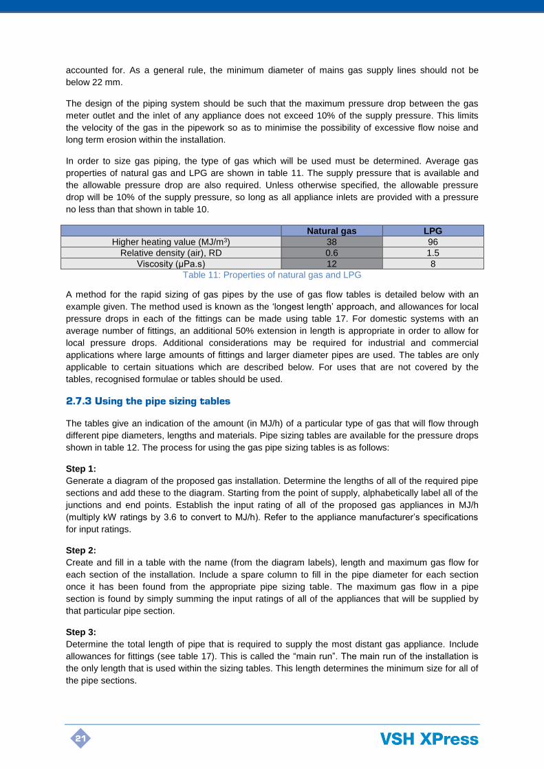
TOWN GAS THROUGH STEELFIX STAINLESS STEEL PIPE WITH PRESSURE DROP OF 0.25 kPa (2.5 kPa supply)
Main run length (m)
O.D. (mm) 2 4 6 8 10 12 14 16 18
15 109* 72 56 47 41 37 34 31 29 18 194* 128 100 84 74 66 60 55 52 22 340* 224* 176 148 129 116 106 98 91 28 712* 470* 369* 310 272 244 222 205 191 35 1323* 644* 505 426 372 334 305 281 262 42 2236* 1484* 1168* 986* 864* 776 708 654 610 54 4843* 3198* 2509* 2113* 1848* 1657* 1511* 1395 1300
76.1 11497* 7698* 6088* 5154* 4529* 4076* 3728* 3451* 3223* 88.9 18062* 12082* 9550* 8082* 7101* 6388* 5842* 5406* 5049* 108 31557* 21100* 16674* 14108* 12394* 11149* 10194* 9433* 8810*
Main run length (m)
O.D. (mm) 20 25 30 35 40 45 50 55 60
15 27 24 21 19 18 17 16 15 14 18 49 42 38 35 32 30 28 26 25 22 85 75 67 61 56 53 49 47 44 28 179 157 141 128 118 110 104 98 93 35 246 215 193 176 163 152 142 134 128 42 574 503 451 412 381 355 334 316 300 54 1221 1068 958 873 806 751 706 666 633
76.1 3032* 2665 2398 2193 2030 1897 1784 1689 1606 88.9 4750* 4173* 3754 3433 3177 2967 2791 2641 2511 108 8287* 7280* 6548* 5988* 5541* 5175 4868 4605 4379
Table 13C
TOWN GAS THROUGH STEELFIX STAINLESS STEEL PIPE WITH PRESSURE DROP OF 0.4 kPa (4.0 kPa supply)
Main run length (m)
O.D. (mm) 2 4 6 8 10 12 14 16 18
15 144* 95* 74 63 55 49 45 41 38 18 258* 170* 133 112 98 88 80 74 69 22 450* 297* 233* 196 172 154 140 129 121 28 944* 623* 489* 411* 360 323 294 272 253 35 1752* 1158* 908* 765* 669* 600* 547* 505 471 42 2951* 1959* 1542* 1301* 1140* 1024* 935* 864* 806 54 6415* 4237* 3324* 2799* 2449* 2196* 2002* 1848* 1723*
76.1 15092* 10104* 7991* 6765* 5945* 5350* 4893* 4529* 4231* 88.9 23723* 15869* 12543* 10615* 9326* 8390* 7672* 7101* 6632* 108 41460* 27722* 21906* 18536* 16283* 14647* 13393* 12394* 11574*
Main run length (m)
O.D. (mm) 20 25 30 35 40 45 50 55 60
15 36 31 28 26 24 22 21 20 19 18 64 56 50 46 42 40 37 35 33 22 113 99 89 81 75 70 65 62 59 28 238 208 186 170 157 146 137 130 123 35 442 387 347 317 292 272 256 242 229 42 757 664 596 544 503 469 441 417 396 54 1617* 1415 1269 1157 1068 996 935 883 838
76.1 3981* 3498* 3148* 2879* 2665 2489 2342 2216 2108 88.9 6238* 5481* 4931* 4509* 4173* 3897* 3666 3469 3298 108 10888* 9564* 8603* 7867* 7280* 6799* 6395* 6051* 5753*
Table 13D
25
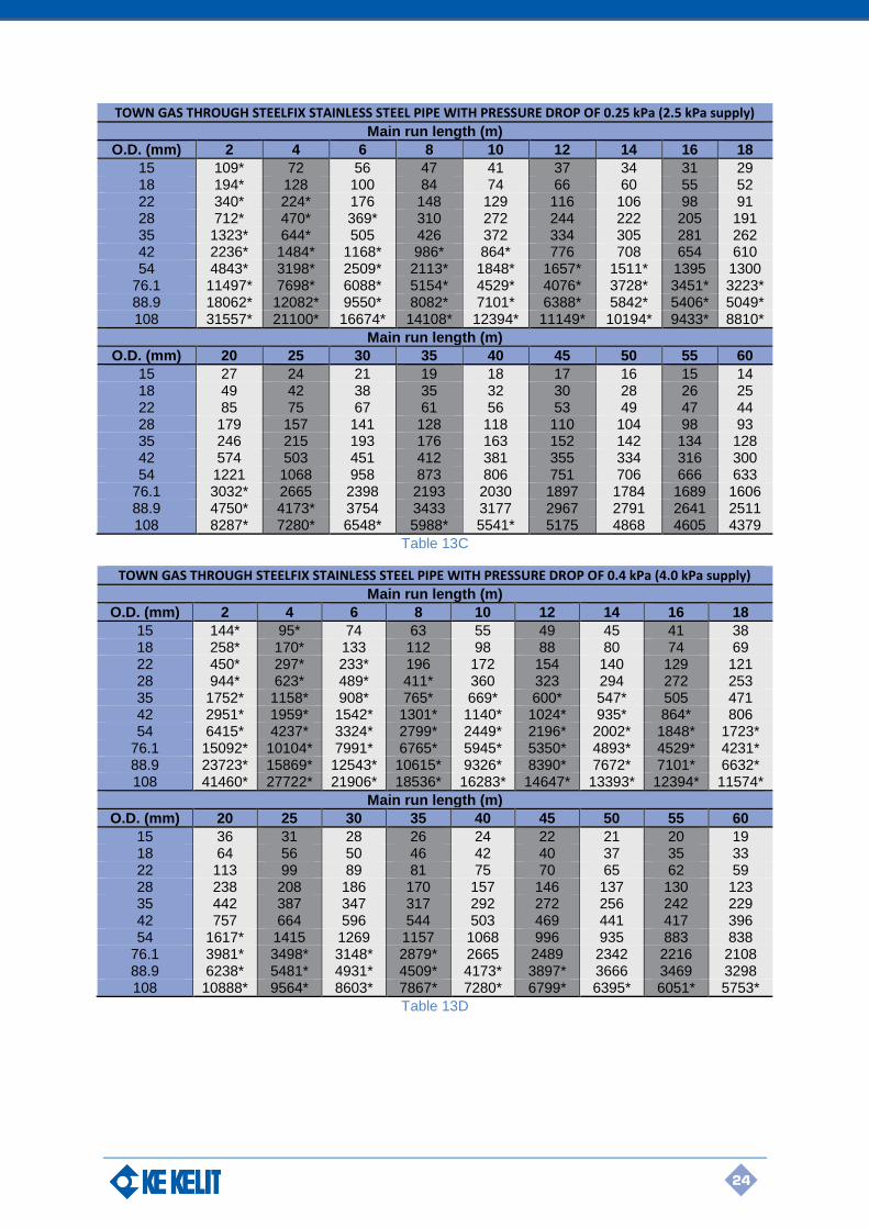
2nd Gas Family (Natural Gas) – VSH XPress Stainless Steel GAS Systems
Density: 0.79 kg/m3
Viscosity: 0.000015 Pa.s
Surface Roughness: 0.0015 mm
NATURAL GAS IN STEELFIX STAINLESS STEEL PIPE WITH PRESSURE DROP OF 0.125 kPa (1.25 kPa supply)
Main run length (m)
O.D. (mm) 2 4 6 8 10 12 14 16 18
15 135 89 70 59 52 46 42 39 36 18 240 159 125 105 92 82 75 69 65 22 423* 280 219 185 162 145 132 122 114 28 887* 586 460 387 339 304 277 256 239 35 1629* 1081 850 717 629 564 515 476 444 42 3003* 1966* 1534 1286 1122 1004 914 842 783 54 5894* 3913* 3079* 2598 2277 2044 1866 1724 1608
76.1 14473* 9699* 7674* 6499* 5713* 5142 4704 4355 4069 88.9 22442* 15061* 11927* 10107* 8889* 8004* 7325 6783 6339 108 39083* 26219* 20759* 17590* 15469* 13927* 12744* 11800* 11026
Main run length (m)
O.D. (mm) 20 25 30 35 40 45 50 55 60
15 34 30 27 24 23 21 20 19 18 18 61 53 48 44 40 37 35 33 32 22 107 94 84 77 71 66 62 58 56 28 224 196 176 160 148 138 130 122 116 35 417 365 328 299 277 258 242 229 218 42 735 641 573 522 481 447 419 396 375 54 1511 1325 1189 1086 1003 936 879 831 789
76.1 3829 3366 3029 2771 2566 2397 2255 2135 2030 88.9 5966 5247 4724 4323 4004 3741 3521 3333 3170 108 10377 9126 8216 7518 6962 6505 6122 5795 5512
Table 14A
NATURAL GAS IN STEELFIX STAINLESS STEEL PIPE WITH PRESSURE DROP OF 0.2 kPa (2.0 kPa supply)
Main run length (m)
O.D. (mm) 2 4 6 8 10 12 14 16 18
15 179 118 93 78 68 61 56 52 48 18 318* 210 165 139 122 109 100 92 86 22 560* 370 290 245 214 192 175 162 151 28 1174* 776* 609 513 449 403 367 339 316 35 2152* 1428* 1123 947 830 745 680 629 586 42 4003* 2620* 2045* 1715* 1496 1338 1218 1122 1044 54 7782* 5166* 4065* 3429* 3006 2699 2464 2277 2123
76.1 18986* 12723* 10067* 8526* 7495* 6746* 6171* 5713* 5338 88.9 29411* 19738* 15631* 13246* 11650* 10490* 9599* 8889* 8307* 108 51232* 34370* 27212* 23057* 20277* 18256* 16705* 15469* 14454*
Main run length (m)
O.D. (mm) 20 25 30 35 40 45 50 55 60
15 45 40 35 32 30 28 26 25 23 18 80 70 63 58 53 50 47 44 42 22 142 124 111 101 94 87 82 77 74 28 297 260 233 212 196 183 172 162 154 35 551 483 433 395 365 341 320 303 287 42 979 854 764 695 641 596 559 528 500 54 1995 1749 1570 1433 1325 1235 1161 1097 1042
76.1 5023 4415 3974 3636 3366 3144 2959 2800 2663 88.9 7818 6876 6191 5666 5247 4903 4615 4368 4155 108 13603* 11963* 10770 9855 9126 8527 8025 7597 7225
Table 14B

26
NATURAL GAS THROUGH STEELFIX STAINLESS STEEL PIPE WITH PRESSURE DROP OF 0.3 kPa (3.0 kPa supply)
Main run length (m)
O.D. (mm) 2 4 6 8 10 12 16 18
15 228* 151 118 100 87 78 71 66 61
18 405* 268 210 177 155 139 127 117 109
22 713* 471* 370 312 273 245 223 206 192
28 1496* 989* 776* 653 572 513 468 432 403
35 2736* 1815* 1428* 1204* 1055 947 865 799 745
42 5129* 3357* 2620* 2197* 1917* 1715* 1561 1438 1338
54 9890* 6565* 5166* 4358* 3820* 3429* 3131* 2893 2699
76.1 23995* 16080* 12723* 10775* 9473* 8526* 7800* 7221* 6746*
88.9 37140* 24924* 19738* 16727* 14711* 13246* 12122* 11225* 10490*
108 64707* 43410* 34370* 29122* 25610* 23057* 21099* 19537* 18256*
Main run length (m)
O.D. (mm) 20 25 30 35 40 45 50 55 60
15 58 50 45 41 38 35 33 31 30
18 102 90 80 73 68 63 59 56 53
22 180 158 142 129 119 111 104 99 94
28 378 331 297 271 250 233 219 207 196
35 700 614 551 503 465 433 407 385 365
42 1255 1095 979 891 821 764 717 676 641
54 2536 2222 1995 1821 1683 1570 1475 1394 1325
76.1 6348* 5580 5023 4595 4254 3974 3740 3539 3366
88.9 9873* 8683* 7818 7155 6626 6191 5827 5516 5247
108 17181* 15109* 13603* 12448* 11526* 10770 10136 9595 9126
Table 14C
NATURAL GAS THROUGH STEELFIX STAINLESS STEEL PIPE WITH PRESSURE DROP OF 0.4 kPa (4.0 kPa supply)
Main run length (m)
O.D. (mm) 2 4 6 8 10 12 14 16 18
15 271* 179 141 118 104 93 85 78 73 18 481* 318* 250 210 184 165 151 139 130 22 846* 560* 439* 370 324 290 265 245 228 28 1776* 1174* 922* 776* 679 609 556 513 478 35 3244* 2152* 1693* 1428* 1251* 1123 1025 947 884 42 6116* 4003* 3124* 2620* 2286* 2045* 1861* 1715* 1596 54 11723* 7782* 6124* 5166* 4528* 4065* 3711* 3429* 3199*
76.1 28332* 18986* 15022* 12723* 11185* 10067* 9209* 8526* 7965* 88.9 43825* 29411* 23291* 19738* 17360* 15631* 14304* 13246* 12378* 108 76366* 51232* 40563* 34370* 30225* 27212* 24901* 23057* 21545*
Main run length (m)
O.D. (mm) 20 25 30 35 40 45 50 55 60
15 68 60 54 49 45 42 40 37 35 18 122 107 96 87 80 75 70 67 63 22 214 187 168 153 142 132 124 117 111 28 449 393 352 321 297 277 260 245 233 35 830 727 653 596 551 514 483 456 433 42 1496 1305 1168 1063 979 911 854 806 764 54 3006 2634 2365 2159 1995 1861 1749 1653 1570
76.1 7495* 6589* 5930* 5425 5023 4692 4415 4179 3974 88.9 11650* 10246* 9226* 8443* 7818 7306 6876 6509 6191 108 20277* 17832* 16054* 14690* 13603* 12711* 11963* 11324 10770
Table 14D

27
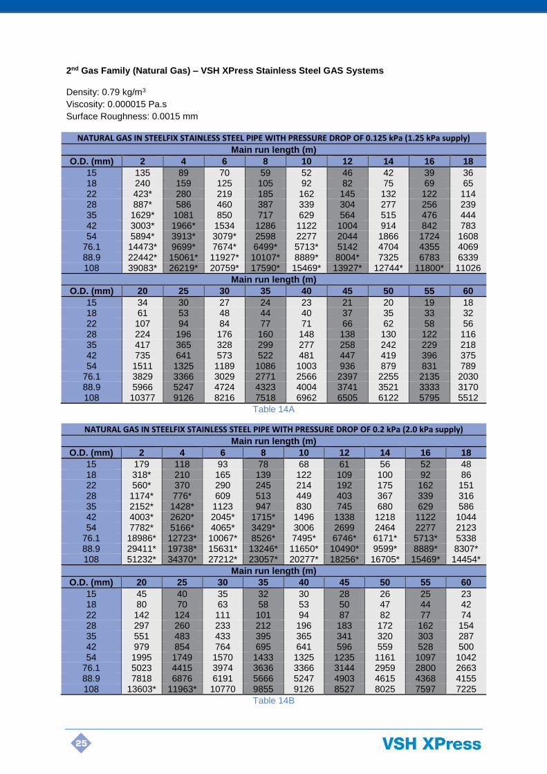
1st Gas Family – VSH XPress Copper GAS Systems
Density: 0.61 kg/m3
Viscosity: 0.000015 Pa.s
Surface Roughness: 0.0015 mm
TOWN GAS THROUGH COPPERFIX COPPER PIPE WITH PRESSURE DROP OF 0.085 kPa (0.85 kPa supply)
Main run length (m)
O.D. (mm) 2 4 6 8 10 12 14 16 18
15 57 37 29 25 21 19 18 16 15 18 101 67 52 44 38 34 31 29 27 22 188 124 97 82 72 64 59 54 50 28 348 230 181 152 133 119 109 101 94 35 694* 459 360 303 265 238 217 200 187 42 1182* 785 618 521 457 410 374 346 323 54 2365* 1568* 1233 1039 910 817 746 689 642
Main run length (m)
O.D. (mm) 20 25 30 35 40 45 50 55 60
15 14 12 11 10 - - - - - 18 25 22 20 18 17 16 15 14 13 22 47 41 37 34 31 29 27 26 24 28 88 77 69 63 58 54 51 48 46 35 175 153 137 125 116 108 101 96 91 42 303 266 239 218 201 188 176 167 158 54 603 529 474 433 400 373 350 331 315
Table 15A
TOWN GAS THROUGH COPPERFIX COPPER PIPE WITH PRESSURE DROP OF 0.15 kPa (1.5 kPa supply)
Main run length (m)
O.D. (mm) 2 4 6 8 10 12 14 16 18
15 80 53 41 35 30 27 25 23 21 18 143* 94 74 62 54 49 44 41 38 22 265* 175 137 115 101 90 82 76 71 28 488* 323 253 213 187 168 153 141 132 35 975* 644* 505 426 372 334 305 281 262 42 1653* 1098* 864* 729 639 574 524 484 451 54 3313* 2196* 1726* 1456* 1275 1144 1044 965 900
Main run length (m)
O.D. (mm) 20 25 30 35 40 45 50 55 60
15 20 17 16 14 13 12 11 11 10 18 36 31 28 25 23 22 21 19 18 22 67 58 52 48 44 41 38 36 34 28 124 108 97 89 82 76 72 68 64 35 246 215 193 176 163 152 142 134 128 42 424 372 334 305 282 263 247 233 222 54 845 740 665 606 560 522 491 464 441
Table 15B

28
TOWN GAS THROUGH COPPERFIX COPPER PIPE WITH PRESSURE DROP OF 0.25 kPa (2.5 kPa supply)
Main run length (m)
O.D. (mm) 2 4 6 8 10 12 14 16 18
15 109* 72 56 47 41 37 34 31 29 18 194* 128* 100 84 74 66 60 55 52 22 360* 238* 186 157 137 123 112 103 96 28 661* 437* 343 289 253 227 207 191 178 35 1323* 874* 686* 578* 505 453 413 382 356 42 2236* 1484* 1168* 986* 864* 776 708 654 610 54 4485* 2973* 2338* 1971* 1726* 1550* 1414 1306 1218
Main run length (m)
O.D. (mm) 20 25 30 35 40 45 50 55 60
15 27 24 21 19 18 17 16 15 14 18 49 42 38 35 32 30 28 26 25 22 90 79 71 65 60 56 52 49 47 28 168 147 132 120 111 103 97 92 87 35 334 292 262 239 221 206 193 182 173 42 574 503 451 412 381 355 334 316 300 54 1144 1003 900 821 759 707 665 628 596
Table 15C
TOWN GAS THROUGH COPPERFIX COPPER PIPE WITH PRESSURE DROP OF 0.4 kPa (4.0 kPa supply)
Main run length (m)
O.D. (mm) 2 4 6 8 10 12 14 16 18
15 144* 95* 74 63 55 49 45 41 38 18 258* 170* 133 112 98 88 80 74 69 22 477* 315* 247* 208* 182 163 148 137 128 28 875* 579* 455* 383* 335 301 274 253 236 35 1752* 1158* 908* 765* 669* 600* 547* 505 471 42 2951* 1959* 1542* 1301* 1140* 1024* 935* 864* 806 54 5928* 3929* 3089* 2605* 2282* 2048* 1869* 1726* 1610*
Main run length (m)
O.D. (mm) 20 25 30 35 40 45 50 55 60
15 36 31 28 26 24 22 21 20 19 18 64 56 50 46 42 40 37 35 33 22 120 105 94 86 79 74 69 65 62 28 222 194 174 159 147 137 128 121 115 35 442 387 347 317 292 272 256 242 229 42 757 664 596 544 503 469 441 417 396 54 1512* 1325 1189 1085 1003 935 878 830 788
Table 15D
29
2nd Gas Family – VSH XPress Copper GAS Systems
Density: 0.79 kg/m3
Viscosity: 0.000015 Pa.s
Surface roughness: 0.0015 mm
NATURAL GAS IN COPPERFIX COPPER PIPE WITH PRESSURE DROP OF 0.125 kPa (1.25 kPa supply)
Main run length (m)
O.D. (mm) 2 4 6 8 10 12 14 16 18
15 135 89 70 59 52 46 42 39 36 18 240 159 125 105 92 82 75 69 65 22 448* 296 232 196 171 154 140 129 120 28 827* 547 430 362 317 284 259 240 223 35 1629* 1081 850 717 629 564 515 476 444 42 3003* 1966* 1534 1286 1122 1004 914 842 783 54 5492* 3657* 2883 2436 2137 1920 1754 1622 1514
Main run length (m)
O.D. (mm) 20 25 30 35 40 45 50 55 60
15 34 30 27 24 23 21 20 19 18 18 61 53 48 44 40 37 35 33 32 22 113 99 89 81 75 70 65 62 59 28 210 184 165 150 139 129 122 115 109 35 417 365 328 299 277 258 242 229 218 42 735 641 573 522 481 447 419 396 375 54 1423 1249 1122 1025 948 884 831 786 747
Table 16A
NATURAL GAS IN COPPERFIX COPPER PIPE WITH PRESSURE DROP OF 0.2 kPa (2.0 kPa supply)
Main run length (m)
O.D. (mm) 2 4 6 8 10 12 14 16 18
15 179 118 93 78 68 61 56 52 48 18 318* 210 165 139 122 109 100 92 86 22 593* 392 308 259 227 203 185 171 160 28 1094* 724 569 479 419 376 343 317 295 35 2152* 1428* 1123 947 830 745 680 629 586 42 4003* 2620* 2045* 1715* 1496 1338 1218 1122 1044 54 7235* 4818* 3799* 3209* 2815 2530 2311 2137 1994
Main run length (m)
O.D. (mm) 20 25 30 35 40 45 50 55 60
15 45 40 35 32 30 28 26 25 23 18 80 70 63 58 53 50 47 44 42 22 150 131 118 107 99 92 87 82 78 28 278 243 218 199 184 171 161 152 144 35 551 483 433 395 365 341 320 303 287 42 979 854 764 695 641 596 559 528 500 54 1875 1645 1478 1350 1249 1165 1095 1036 984
Table 16B

30
NATURAL GAS IN COPPERFIX COPPER PIPE WITH PRESSURE DROP OF 0.3 kPa (3.0 kPa supply)
Main run length (m)
O.D. (mm) 2 4 6 8 10 12 14 16 18
15 228* 151 118 100 87 78 71 66 61 18 405* 268 210 177 155 139 127 117 109 22 755* 499* 392 330 289 259 236 218 203 28 1393* 922* 724 610 534 479 437 404 376 35 2736* 1815* 1428* 1204* 1055 947 865 799 745 42 5129* 3357* 2620* 2197* 1917* 1715* 1561 1438 1338 54 9178* 6112* 4818* 4070* 3571* 3209* 2931 2711 2530
Main run length (m)
O.D. (mm) 20 25 30 35 40 45 50 55 60
15 58 50 45 41 38 35 33 31 30 18 102 90 80 73 68 63 59 56 53 22 191 167 150 137 126 118 110 104 99 28 353 309 278 253 234 218 205 193 184 35 700 614 551 503 465 433 407 385 365 42 1255 1095 979 891 821 764 717 676 641 54 2378 2086 1875 1713 1584 1478 1389 1314 1249
Table 16C
NATURAL GAS THROUGH COPPERFIX COPPER PIPE WITH PRESSURE DROP OF 0.4 kPa (4.0 kPa supply)
Main run length (m)
O.D. (mm) 2 4 6 8 10 12 14 16 18
15 271* 179 141 118 104 93 85 78 73 18 481* 318* 250 210 184 165 151 139 130 22 897* 593* 465* 392 343 308 281 259 241 28 1654* 1094* 859* 724 634 569 519 479 447 35 3244* 2152* 1693* 1428* 1251* 1123 1025 947 884 42 6116* 4003* 3124* 2620* 2286* 2045* 1861* 1715* 1596 54 10864* 7235* 5704* 4818* 4227* 3799* 3470* 3209* 2995
Main run length (m)
O.D. (mm) 20 25 30 35 40 45 50 55 60
15 68 60 54 49 45 42 40 37 35 18 122 107 96 87 80 75 70 67 63 22 227 198 178 162 150 140 131 124 118 28 419 367 329 300 278 259 243 230 218 35 830 727 653 596 551 514 483 456 433 42 1496 1305 1168 1063 979 911 854 806 764 54 2815 2470 2219 2028 1875 1750 1645 1555 1478
Table 16D
31
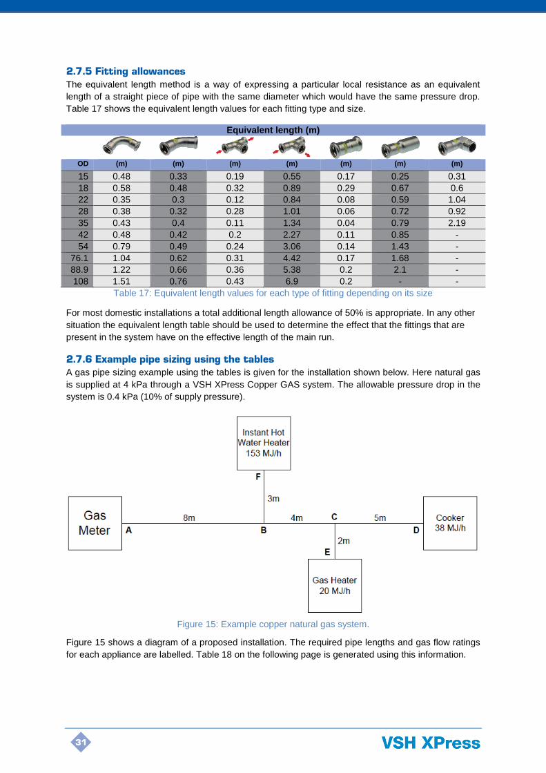
2.7.5 Fitting allowances
The equivalent length method is a way of expressing a particular local resistance as an equivalent
length of a straight piece of pipe with the same diameter which would have the same pressure drop.
Table 17 shows the equivalent length values for each fitting type and size.
Equivalent length (m)
OD (m) (m) (m) (m) (m) (m) (m)
15 0.48 0.33 0.19 0.55 0.17 0.25 0.31
18 0.58 0.48 0.32 0.89 0.29 0.67 0.6
22 0.35 0.3 0.12 0.84 0.08 0.59 1.04
28 0.38 0.32 0.28 1.01 0.06 0.72 0.92
35 0.43 0.4 0.11 1.34 0.04 0.79 2.19
42 0.48 0.42 0.2 2.27 0.11 0.85 -
54 0.79 0.49 0.24 3.06 0.14 1.43 -
76.1 1.04 0.62 0.31 4.42 0.17 1.68 -
88.9 1.22 0.66 0.36 5.38 0.2 2.1 -
108 1.51 0.76 0.43 6.9 0.2 - -
Table 17: Equivalent length values for each type of fitting depending on its size
For most domestic installations a total additional length allowance of 50% is appropriate. In any other
situation the equivalent length table should be used to determine the effect that the fittings that are
present in the system have on the effective length of the main run.
2.7.6 Example pipe sizing using the tables
A gas pipe sizing example using the tables is given for the installation shown below. Here natural gas
is supplied at 4 kPa through a VSH XPress Copper GAS system. The allowable pressure drop in the
system is 0.4 kPa (10% of supply pressure).
Figure 15 shows a diagram of a proposed installation. The required pipe lengths and gas flow ratings
for each appliance are labelled. Table 18 on the following page is generated using this information.
Figure 15: Example copper natural gas system.

32
Pipe Section Length (m) Gas Flow Demand (MJ/h) Pipe O.D. (mm)
A-B 8 211 (153 + 20 + 38)
B-C 4 58 (20 + 38)
C-D 5 38
C-E 2 20
B-F 3 153
Table 18: Table of system information used for the rapid sizing of pipe sections.
The most distant fixture from the gas meter is the gas cooker (A-D) at a distance of 17 m. An
additional length allowance of 50% is suitable for this small domestic installation, therefore the main
run length is 17 m x 1.5 = 25.5 m. This means the 30 m column of the table must be used for the main
run.
Table 16D is the appropriate table to use for the conveyance of natural gas through copper piping
with a maximum pressure drop of 0.4 kPa. For pipe section A-B, the maximum gas flow demand is
211 MJ/h. Looking down the 30 m column of table 16D, the 28 mm pipe is capable of supplying a gas
flow of 329 MJ/h in these conditions, and is the smallest size capable of carrying at least the required
211 MJ/h. 28 mm pipe is therefore the minimum allowable size for pipe run A-B.
In a similar fashion, it is found that pipe run B-C must be at least 18 mm (96 MJ/h) in size as this is the
smallest pipe which is capable of carrying at least the required 58 MJ/h. The remaining pipe sections
are sized using the same process, and all use the 30 m column for the effective main run length of
25.5 m.
Table 19 is the completed pipe sizing table with the size of all runs determined. It must be kept in
mind that if the gas flow lies between two rows of the table, then the larger of the two determines the
suitable size.
Pipe Section Length (m) Demand (MJ/h) Pipe O.D. (mm)
A-B 8 211 28
B-C 4 58 18
C-D 5 38 15
C-E 2 20 15
B-F 3 153 22
Table 19: Completed table with minimum sizes for each pipe section.
For more complex or high-pressure systems, more rigorous design methods will be more appropriate.
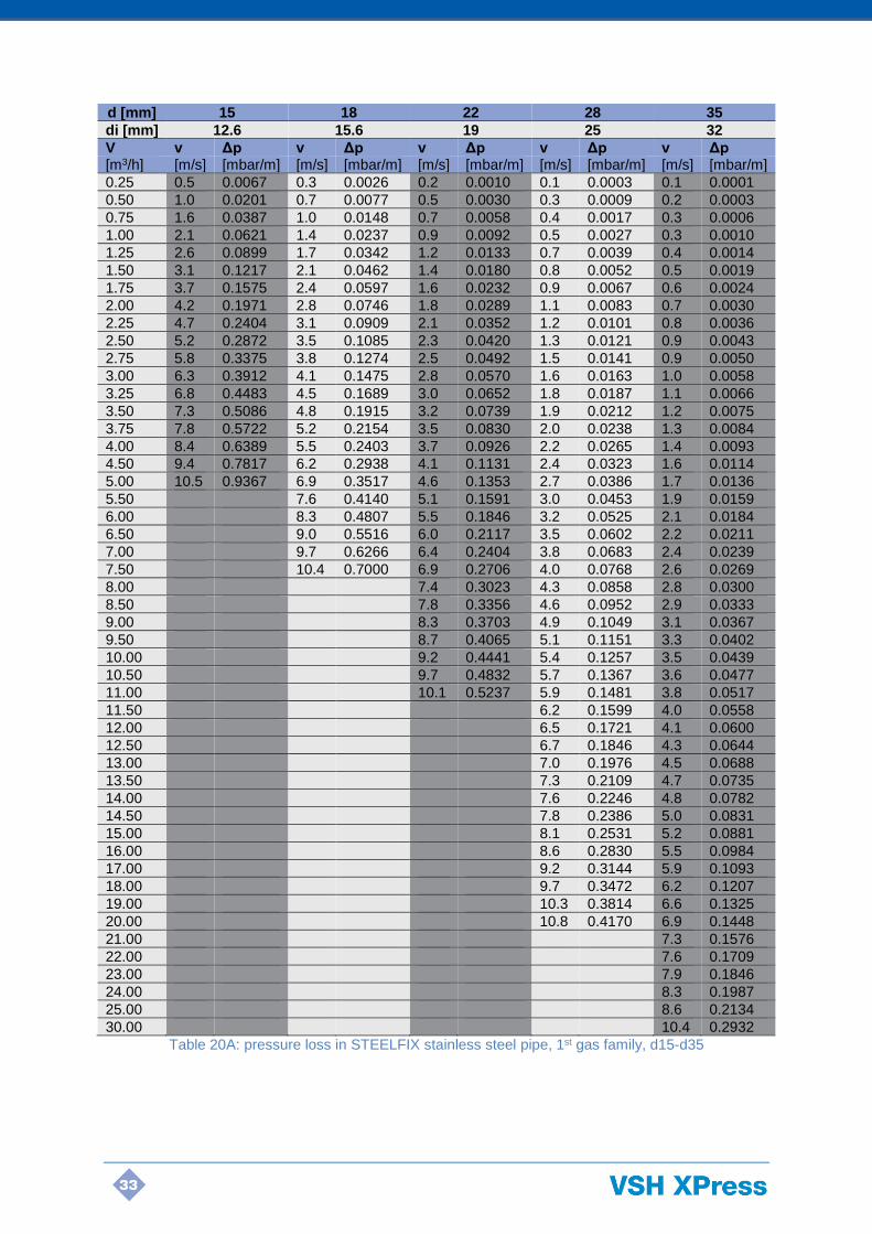
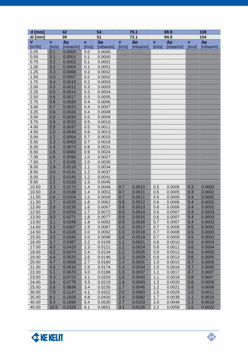
2.7.7 Pressure losses in terms of velocity and flow rate
Tables 20A-B on the following pages give the pressure loss [Δp] in the pipe for town gas (1st gas
family) with density 0.61 kg/m3 and viscosity 0.000015 Pa.s as a function of the volumetric flow rate
[V] and the flow velocity [v] for STEELFIX stainless steel 1.4401 pipes with a surface roughness of
0.0015 mm.
33
d [mm] 15 18 22 28 35
di [mm] 12.6 15.6 19 25 32
V v Δp v Δp v Δp v Δp v Δp [m3/h] [m/s] [mbar/m] [m/s] [mbar/m] [m/s] [mbar/m] [m/s] [mbar/m] [m/s] [mbar/m]
0.25 0.5 0.0067 0.3 0.0026 0.2 0.0010 0.1 0.0003 0.1 0.0001
0.50 1.0 0.0201 0.7 0.0077 0.5 0.0030 0.3 0.0009 0.2 0.0003
0.75 1.6 0.0387 1.0 0.0148 0.7 0.0058 0.4 0.0017 0.3 0.0006
1.00 2.1 0.0621 1.4 0.0237 0.9 0.0092 0.5 0.0027 0.3 0.0010
1.25 2.6 0.0899 1.7 0.0342 1.2 0.0133 0.7 0.0039 0.4 0.0014
1.50 3.1 0.1217 2.1 0.0462 1.4 0.0180 0.8 0.0052 0.5 0.0019
1.75 3.7 0.1575 2.4 0.0597 1.6 0.0232 0.9 0.0067 0.6 0.0024
2.00 4.2 0.1971 2.8 0.0746 1.8 0.0289 1.1 0.0083 0.7 0.0030
2.25 4.7 0.2404 3.1 0.0909 2.1 0.0352 1.2 0.0101 0.8 0.0036
2.50 5.2 0.2872 3.5 0.1085 2.3 0.0420 1.3 0.0121 0.9 0.0043
2.75 5.8 0.3375 3.8 0.1274 2.5 0.0492 1.5 0.0141 0.9 0.0050
3.00 6.3 0.3912 4.1 0.1475 2.8 0.0570 1.6 0.0163 1.0 0.0058
3.25 6.8 0.4483 4.5 0.1689 3.0 0.0652 1.8 0.0187 1.1 0.0066
3.50 7.3 0.5086 4.8 0.1915 3.2 0.0739 1.9 0.0212 1.2 0.0075
3.75 7.8 0.5722 5.2 0.2154 3.5 0.0830 2.0 0.0238 1.3 0.0084
4.00 8.4 0.6389 5.5 0.2403 3.7 0.0926 2.2 0.0265 1.4 0.0093
4.50 9.4 0.7817 6.2 0.2938 4.1 0.1131 2.4 0.0323 1.6 0.0114
5.00 10.5 0.9367 6.9 0.3517 4.6 0.1353 2.7 0.0386 1.7 0.0136
5.50 7.6 0.4140 5.1 0.1591 3.0 0.0453 1.9 0.0159
6.00 8.3 0.4807 5.5 0.1846 3.2 0.0525 2.1 0.0184
6.50 9.0 0.5516 6.0 0.2117 3.5 0.0602 2.2 0.0211
7.00 9.7 0.6266 6.4 0.2404 3.8 0.0683 2.4 0.0239
7.50 10.4 0.7000 6.9 0.2706 4.0 0.0768 2.6 0.0269
8.00 7.4 0.3023 4.3 0.0858 2.8 0.0300
8.50 7.8 0.3356 4.6 0.0952 2.9 0.0333
9.00 8.3 0.3703 4.9 0.1049 3.1 0.0367
9.50 8.7 0.4065 5.1 0.1151 3.3 0.0402
10.00 9.2 0.4441 5.4 0.1257 3.5 0.0439
10.50 9.7 0.4832 5.7 0.1367 3.6 0.0477
11.00 10.1 0.5237 5.9 0.1481 3.8 0.0517
11.50 6.2 0.1599 4.0 0.0558
12.00 6.5 0.1721 4.1 0.0600
12.50 6.7 0.1846 4.3 0.0644
13.00 7.0 0.1976 4.5 0.0688
13.50 7.3 0.2109 4.7 0.0735
14.00 7.6 0.2246 4.8 0.0782
14.50 7.8 0.2386 5.0 0.0831
15.00 8.1 0.2531 5.2 0.0881
16.00 8.6 0.2830 5.5 0.0984
17.00 9.2 0.3144 5.9 0.1093
18.00 9.7 0.3472 6.2 0.1207
19.00 10.3 0.3814 6.6 0.1325
20.00 10.8 0.4170 6.9 0.1448
21.00 7.3 0.1576
22.00 7.6 0.1709
23.00 7.9 0.1846
24.00 8.3 0.1987
25.00 8.6 0.2134
30.00 10.4 0.2932
Table 20A: pressure loss in STEELFIX stainless steel pipe, 1st gas family, d15-d35
34
d [mm] 42 54 76.1 88.9 108
di [mm] 39 51 72.1 84.9 104
V v Δp v Δp v Δp v Δp v Δp [m3/h] [m/s] [mbar/m] [m/s] [mbar/m] [m/s] [mbar/m] [m/s] [mbar/m] [m/s] [mbar/m]
0.25 0.1 0.0000 0.0 0.0000
0.50 0.1 0.0001 0.1 0.0000
0.75 0.2 0.0002 0.1 0.0001
1.00 0.2 0.0004 0.1 0.0001
1.25 0.3 0.0006 0.2 0.0002
1.50 0.3 0.0007 0.2 0.0002
1.75 0.4 0.0010 0.2 0.0003
2.00 0.5 0.0012 0.3 0.0003
2.25 0.5 0.0014 0.3 0.0004
2.50 0.6 0.0017 0.3 0.0005
2.75 0.6 0.0020 0.4 0.0006
3.00 0.7 0.0023 0.4 0.0007
3.25 0.8 0.0026 0.4 0.0008
3.50 0.8 0.0030 0.5 0.0009
3.75 0.9 0.0033 0.5 0.0010
4.00 0.9 0.0037 0.5 0.0011
4.50 1.0 0.0045 0.6 0.0013
5.00 1.2 0.0054 0.7 0.0015
5.50 1.3 0.0063 0.7 0.0018
6.00 1.4 0.0073 0.8 0.0021
6.50 1.5 0.0083 0.9 0.0024
7.00 1.6 0.0095 1.0 0.0027
7.50 1.7 0.0106 1.0 0.0030
8.00 1.9 0.0118 1.1 0.0034
8.50 2.0 0.0131 1.2 0.0037
9.00 2.1 0.0145 1.2 0.0041
9.50 2.2 0.0159 1.3 0.0045
10.00 2.3 0.0173 1.4 0.0049 0.7 0.0010 0.5 0.0005 0.3 0.0002
10.50 2.4 0.0188 1.4 0.0053 0.7 0.0011 0.5 0.0005 0.3 0.0002
11.00 2.6 0.0204 1.5 0.0058 0.7 0.0011 0.5 0.0005 0.4 0.0002
11.50 2.7 0.0220 1.6 0.0062 0.8 0.0012 0.6 0.0006 0.4 0.0002
12.00 2.8 0.0236 1.6 0.0067 0.8 0.0013 0.6 0.0006 0.4 0.0002
12.50 2.9 0.0253 1.7 0.0072 0.9 0.0014 0.6 0.0007 0.4 0.0003
13.00 3.0 0.0271 1.8 0.0077 0.9 0.0015 0.6 0.0007 0.4 0.0003
13.50 3.1 0.0289 1.8 0.0082 0.9 0.0016 0.7 0.0007 0.4 0.0003
14.00 3.3 0.0307 1.9 0.0087 1.0 0.0017 0.7 0.0008 0.5 0.0003
14.50 3.4 0.0326 2.0 0.0092 1.0 0.0018 0.7 0.0008 0.5 0.0003
15.00 3.5 0.0346 2.0 0.0098 1.0 0.0019 0.7 0.0009 0.5 0.0003
16.00 3.7 0.0387 2.2 0.0109 1.1 0.0021 0.8 0.0010 0.5 0.0004
17.00 4.0 0.0429 2.3 0.0121 1.2 0.0024 0.8 0.0011 0.6 0.0004
18.00 4.2 0.0474 2.4 0.0134 1.2 0.0026 0.9 0.0012 0.6 0.0005
19.00 4.4 0.0520 2.6 0.0146 1.3 0.0029 0.9 0.0013 0.6 0.0005
20.00 4.7 0.0568 2.7 0.0160 1.4 0.0031 1.0 0.0015 0.7 0.0006
21.00 4.9 0.0618 2.9 0.0174 1.4 0.0034 1.0 0.0016 0.7 0.0006
22.00 5.1 0.0670 3.0 0.0188 1.5 0.0037 1.1 0.0017 0.7 0.0007
23.00 5.3 0.0723 3.1 0.0203 1.6 0.0040 1.1 0.0018 0.8 0.0007
24.00 5.6 0.0778 3.3 0.0219 1.6 0.0043 1.2 0.0020 0.8 0.0008
25.00 5.8 0.0836 3.4 0.0235 1.7 0.0046 1.2 0.0021 0.8 0.0008
30.00 7.0 0.1147 4.1 0.0322 2.0 0.0063 1.5 0.0029 1.0 0.0011
35.00 8.1 0.1500 4.8 0.0420 2.4 0.0082 1.7 0.0038 1.1 0.0015
40.00 9.3 0.1894 5.4 0.0530 2.7 0.0103 2.0 0.0048 1.3 0.0018
45.00 10.5 0.2328 6.1 0.0651 3.1 0.0126 2.2 0.0058 1.5 0.0022

35
d [mm] 42 54 76.1 88.9 108
di [mm] 39 51 72.1 84.9 104
V v Δp v Δp v Δp v Δp v Δp [m3/h] [m/s] [mbar/m] [m/s] [mbar/m] [m/s] [mbar/m] [m/s] [mbar/m] [m/s] [mbar/m]
50.00 6.8 0.0782 3.4 0.0151 2.5 0.0070 1.6 0.0027
55.00 7.5 0.0924 3.7 0.0179 2.7 0.0082 1.8 0.0032
60.00 8.2 0.1076 4.1 0.0208 2.9 0.0096 2.0 0.0037
65.00 8.8 0.1238 4.4 0.0239 3.2 0.0110 2.1 0.0042
70.00 9.5 0.1410 4.8 0.0272 3.4 0.0125 2.3 0.0048
75.00 10.2 0.1592 5.1 0.0307 3.7 0.0141 2.5 0.0054
80.00 10.9 0.1784 5.4 0.0344 3.9 0.0158 2.6 0.0060
85.00 5.8 0.0382 4.2 0.0176 2.8 0.0067
90.00 6.1 0.0422 4.4 0.0194 2.9 0.0074
95.00 6.5 0.0464 4.7 0.0214 3.1 0.0081
100.00 6.8 0.0508 4.9 0.0234 3.3 0.0089
105.00 7.1 0.0553 5.2 0.0254 3.4 0.0097
110.00 7.5 0.0601 5.4 0.0276 3.6 0.0105
115.00 7.8 0.0650 5.6 0.0298 3.8 0.0114
120.00 8.2 0.0700 5.9 0.0322 3.9 0.0123
125.00 8.5 0.0752 6.1 0.0345 4.1 0.0132
130.00 8.8 0.0806 6.4 0.0370 4.3 0.0141
135.00 9.2 0.0862 6.6 0.0396 4.4 0.0151
140.00 9.5 0.0919 6.9 0.0422 4.6 0.0161
145.00 9.9 0.0977 7.1 0.0449 4.7 0.0171
150.00 10.2 0.1038 7.4 0.0476 4.9 0.0181
160.00 7.9 0.0534 5.2 0.0203
170.00 8.3 0.0594 5.6 0.0226
180.00 8.8 0.0657 5.9 0.0250
190.00 9.3 0.0723 6.2 0.0275
200.00 9.8 0.0791 6.5 0.0301
210.00 10.3 0.0863 6.9 0.0328
220.00 7.2 0.0356
230.00 7.5 0.0385
240.00 7.8 0.0415
250.00 8.2 0.0446
300.00 9.8 0.0616
Table 20B: pressure loss in STEELFIX stainless steel pipe, 1st gas family, d42-d108
Tables 21A-B on the following pages give the pressure loss [Δp] in the pipe for natural gas (2nd gas
family) with density 0.79 kg/m3 and viscosity 0.000015 Pa.s as a function of the volumetric flow rate
[V] and the flow velocity [v] for STEELFIX stainless steel 1.4401 pipes with a surface roughness of
0.0015 mm.
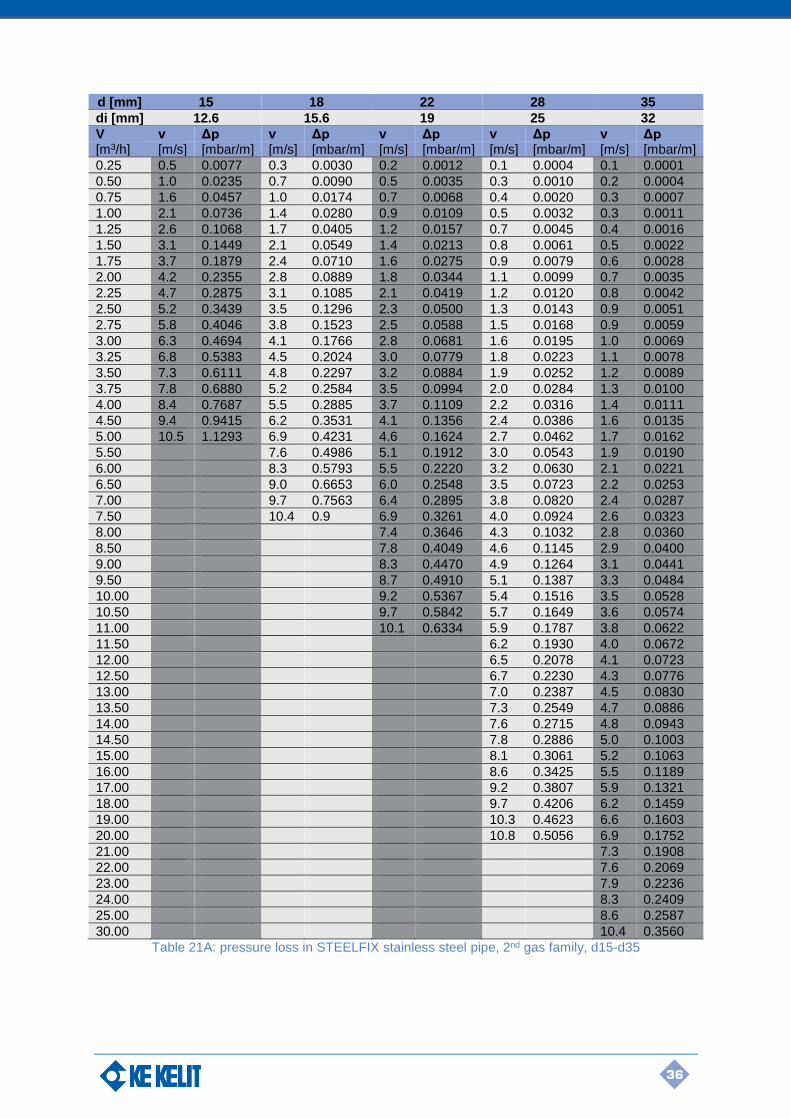
36
d [mm] 15 18 22 28 35
di [mm] 12.6 15.6 19 25 32
V v Δp v Δp v Δp v Δp v Δp [m3/h] [m/s] [mbar/m] [m/s] [mbar/m] [m/s] [mbar/m] [m/s] [mbar/m] [m/s] [mbar/m]
0.25 0.5 0.0077 0.3 0.0030 0.2 0.0012 0.1 0.0004 0.1 0.0001
0.50 1.0 0.0235 0.7 0.0090 0.5 0.0035 0.3 0.0010 0.2 0.0004
0.75 1.6 0.0457 1.0 0.0174 0.7 0.0068 0.4 0.0020 0.3 0.0007
1.00 2.1 0.0736 1.4 0.0280 0.9 0.0109 0.5 0.0032 0.3 0.0011
1.25 2.6 0.1068 1.7 0.0405 1.2 0.0157 0.7 0.0045 0.4 0.0016
1.50 3.1 0.1449 2.1 0.0549 1.4 0.0213 0.8 0.0061 0.5 0.0022
1.75 3.7 0.1879 2.4 0.0710 1.6 0.0275 0.9 0.0079 0.6 0.0028
2.00 4.2 0.2355 2.8 0.0889 1.8 0.0344 1.1 0.0099 0.7 0.0035
2.25 4.7 0.2875 3.1 0.1085 2.1 0.0419 1.2 0.0120 0.8 0.0042
2.50 5.2 0.3439 3.5 0.1296 2.3 0.0500 1.3 0.0143 0.9 0.0051
2.75 5.8 0.4046 3.8 0.1523 2.5 0.0588 1.5 0.0168 0.9 0.0059
3.00 6.3 0.4694 4.1 0.1766 2.8 0.0681 1.6 0.0195 1.0 0.0069
3.25 6.8 0.5383 4.5 0.2024 3.0 0.0779 1.8 0.0223 1.1 0.0078
3.50 7.3 0.6111 4.8 0.2297 3.2 0.0884 1.9 0.0252 1.2 0.0089
3.75 7.8 0.6880 5.2 0.2584 3.5 0.0994 2.0 0.0284 1.3 0.0100
4.00 8.4 0.7687 5.5 0.2885 3.7 0.1109 2.2 0.0316 1.4 0.0111
4.50 9.4 0.9415 6.2 0.3531 4.1 0.1356 2.4 0.0386 1.6 0.0135
5.00 10.5 1.1293 6.9 0.4231 4.6 0.1624 2.7 0.0462 1.7 0.0162
5.50 7.6 0.4986 5.1 0.1912 3.0 0.0543 1.9 0.0190
6.00 8.3 0.5793 5.5 0.2220 3.2 0.0630 2.1 0.0221
6.50 9.0 0.6653 6.0 0.2548 3.5 0.0723 2.2 0.0253
7.00 9.7 0.7563 6.4 0.2895 3.8 0.0820 2.4 0.0287
7.50 10.4 0.9 6.9 0.3261 4.0 0.0924 2.6 0.0323
8.00 7.4 0.3646 4.3 0.1032 2.8 0.0360
8.50 7.8 0.4049 4.6 0.1145 2.9 0.0400
9.00 8.3 0.4470 4.9 0.1264 3.1 0.0441
9.50 8.7 0.4910 5.1 0.1387 3.3 0.0484
10.00 9.2 0.5367 5.4 0.1516 3.5 0.0528
10.50 9.7 0.5842 5.7 0.1649 3.6 0.0574
11.00 10.1 0.6334 5.9 0.1787 3.8 0.0622
11.50 6.2 0.1930 4.0 0.0672
12.00 6.5 0.2078 4.1 0.0723
12.50 6.7 0.2230 4.3 0.0776
13.00 7.0 0.2387 4.5 0.0830
13.50 7.3 0.2549 4.7 0.0886
14.00 7.6 0.2715 4.8 0.0943
14.50 7.8 0.2886 5.0 0.1003
15.00 8.1 0.3061 5.2 0.1063
16.00 8.6 0.3425 5.5 0.1189
17.00 9.2 0.3807 5.9 0.1321
18.00 9.7 0.4206 6.2 0.1459
19.00 10.3 0.4623 6.6 0.1603
20.00 10.8 0.5056 6.9 0.1752
21.00 7.3 0.1908
22.00 7.6 0.2069
23.00 7.9 0.2236
24.00 8.3 0.2409
25.00 8.6 0.2587
30.00 10.4 0.3560
Table 21A: pressure loss in STEELFIX stainless steel pipe, 2nd gas family, d15-d35

37
d [mm] 42 54 76.1 88.9 108
di [mm] 39 51 72.1 84.9 104
V v Δp v Δp v Δp v Δp v Δp [m3/h] [m/s] [mbar/m] [m/s] [mbar/m] [m/s] [mbar/m] [m/s] [mbar/m] [m/s] [mbar/m]
0.25 0.1 0.0001 0.0 0.0000
0.50 0.1 0.0002 0.1 0.0000
0.75 0.2 0.0003 0.1 0.0001
1.00 0.2 0.0005 0.1 0.0001
1.25 0.3 0.0006 0.2 0.0002
1.50 0.3 0.0009 0.2 0.0003
1.75 0.4 0.0011 0.2 0.0003
2.00 0.5 0.0014 0.3 0.0004
2.25 0.5 0.0017 0.3 0.0005
2.50 0.6 0.0020 0.3 0.0006
2.75 0.6 0.0024 0.4 0.0007
3.00 0.7 0.0027 0.4 0.0008
3.25 0.8 0.0031 0.4 0.0009
3.50 0.8 0.0035 0.5 0.0010
3.75 0.9 0.0040 0.5 0.0011
4.00 0.9 0.0044 0.5 0.0013
4.50 1.0 0.0054 0.6 0.0015
5.00 1.2 0.0064 0.7 0.0018
5.50 1.3 0.0075 0.7 0.0021
6.00 1.4 0.0087 0.8 0.0025
6.50 1.5 0.0100 0.9 0.0028
7.00 1.6 0.0113 1.0 0.0032
7.50 1.7 0.0127 1.0 0.0036
8.00 1.9 0.0142 1.1 0.0040
8.50 2.0 0.0157 1.2 0.0045
9.00 2.1 0.0173 1.2 0.0049
9.50 2.2 0.0190 1.3 0.0054
10.00 2.3 0.0208 1.4 0.0059 0.7 0.0012 0.5 0.0005 0.3 0.0002
10.50 2.4 0.0226 1.4 0.0064 0.7 0.0013 0.5 0.0006 0.3 0.0002
11.00 2.6 0.0245 1.5 0.0069 0.7 0.0014 0.5 0.0006 0.4 0.0002
11.50 2.7 0.0264 1.6 0.0075 0.8 0.0015 0.6 0.0007 0.4 0.0003
12.00 2.8 0.0284 1.6 0.0080 0.8 0.0016 0.6 0.0007 0.4 0.0003
12.50 2.9 0.0305 1.7 0.0086 0.9 0.0017 0.6 0.0008 0.4 0.0003
13.00 3.0 0.0326 1.8 0.0092 0.9 0.0018 0.6 0.0008 0.4 0.0003
13.50 3.1 0.0348 1.8 0.0098 0.9 0.0019 0.7 0.0009 0.4 0.0003
14.00 3.3 0.0370 1.9 0.0104 1.0 0.0020 0.7 0.0009 0.5 0.0004
14.50 3.4 0.0393 2.0 0.0111 1.0 0.0022 0.7 0.0010 0.5 0.0004
15.00 3.5 0.0417 2.0 0.0117 1.0 0.0023 0.7 0.0011 0.5 0.0004
16.00 3.7 0.0466 2.2 0.0131 1.1 0.0026 0.8 0.0012 0.5 0.0005
17.00 4.0 0.0518 2.3 0.0146 1.2 0.0028 0.8 0.0013 0.6 0.0005
18.00 4.2 0.0572 2.4 0.0161 1.2 0.0031 0.9 0.0015 0.6 0.0006
19.00 4.4 0.0628 2.6 0.0176 1.3 0.0034 0.9 0.0016 0.6 0.0006
20.00 4.7 0.0686 2.7 0.0193 1.4 0.0038 1.0 0.0017 0.7 0.0007
21.00 4.9 0.0747 2.9 0.0210 1.4 0.0041 1.0 0.0019 0.7 0.0007
22.00 5.1 0.0810 3.0 0.0227 1.5 0.0044 1.1 0.0020 0.7 0.0008
23.00 5.3 0.0875 3.1 0.0245 1.6 0.0048 1.1 0.0022 0.8 0.0009
24.00 5.6 0.0942 3.3 0.0264 1.6 0.0051 1.2 0.0024 0.8 0.0009
25.00 5.8 0.1011 3.4 0.0284 1.7 0.0055 1.2 0.0026 0.8 0.0010
30.00 7.0 0.1390 4.1 0.0389 2.0 0.0076 1.5 0.0035 1.0 0.0013
35.00 8.1 0.1820 4.8 0.0509 2.4 0.0099 1.7 0.0046 1.1 0.0017
40.00 9.3 0.2301 5.4 0.0643 2.7 0.0124 2.0 0.0057 1.3 0.0022
45.00 10.5 0.2830 6.1 0.0790 3.1 0.0153 2.2 0.0070 1.5 0.0027

38
d [mm] 42 54 76.1 88.9 108
di [mm] 39 51 72.1 84.9 104
V v Δp v Δp v Δp v Δp v Δp [m3/h] [m/s] [mbar/m] [m/s] [mbar/m] [m/s] [mbar/m] [m/s] [mbar/m] [m/s] [mbar/m]
50.00 6.8 0.0950 3.4 0.0183 2.5 0.0084 1.6 0.0032
55.00 7.5 0.1123 3.7 0.0217 2.7 0.0100 1.8 0.0038
60.00 8.2 0.1308 4.1 0.0252 2.9 0.0116 2.0 0.0044
65.00 8.8 0.1506 4.4 0.0290 3.2 0.0133 2.1 0.0051
70.00 9.5 0.1717 4.8 0.0330 3.4 0.0152 2.3 0.0058
75.00 10.2 0.1939 5.1 0.0373 3.7 0.0171 2.5 0.0065
80.00 10.9 0.2173 5.4 0.0417 3.9 0.0192 2.6 0.0073
85.00 5.8 0.0464 4.2 0.0213 2.8 0.0081
90.00 6.1 0.0514 4.4 0.0236 2.9 0.0090
95.00 6.5 0.0565 4.7 0.0259 3.1 0.0099
100.00 6.8 0.0618 4.9 0.0284 3.3 0.0108
105.00 7.1 0.0674 5.2 0.0309 3.4 0.0118
110.00 7.5 0.0732 5.4 0.0336 3.6 0.0128
115.00 7.8 0.0791 5.6 0.0363 3.8 0.0138
120.00 8.2 0.0853 5.9 0.0391 3.9 0.0149
125.00 8.5 0.0917 6.1 0.0421 4.1 0.0160
130.00 8.8 0.0983 6.4 0.0451 4.3 0.0171
135.00 9.2 0.1051 6.6 0.0482 4.4 0.0183
140.00 9.5 0.1121 6.9 0.0514 4.6 0.0195
145.00 9.9 0.1193 7.1 0.0547 4.7 0.0208
150.00 10.2 0.1266 7.4 0.0580 4.9 0.0221
160.00 7.9 0.0651 5.2 0.0247
170.00 8.3 0.0724 5.6 0.0275
180.00 8.8 0.0802 5.9 0.0304
190.00 9.3 0.0882 6.2 0.0335
200.00 9.8 0.0967 6.5 0.0367
210.00 10.3 0.1054 6.9 0.0400
220.00 7.2 0.0434
230.00 7.5 0.0470
240.00 7.8 0.0507
250.00 8.2 0.0545
300.00 9.8 0.0753
Table 21B: pressure loss in STEELFIX stainless steel pipe, 2nd gas family, d42-d108
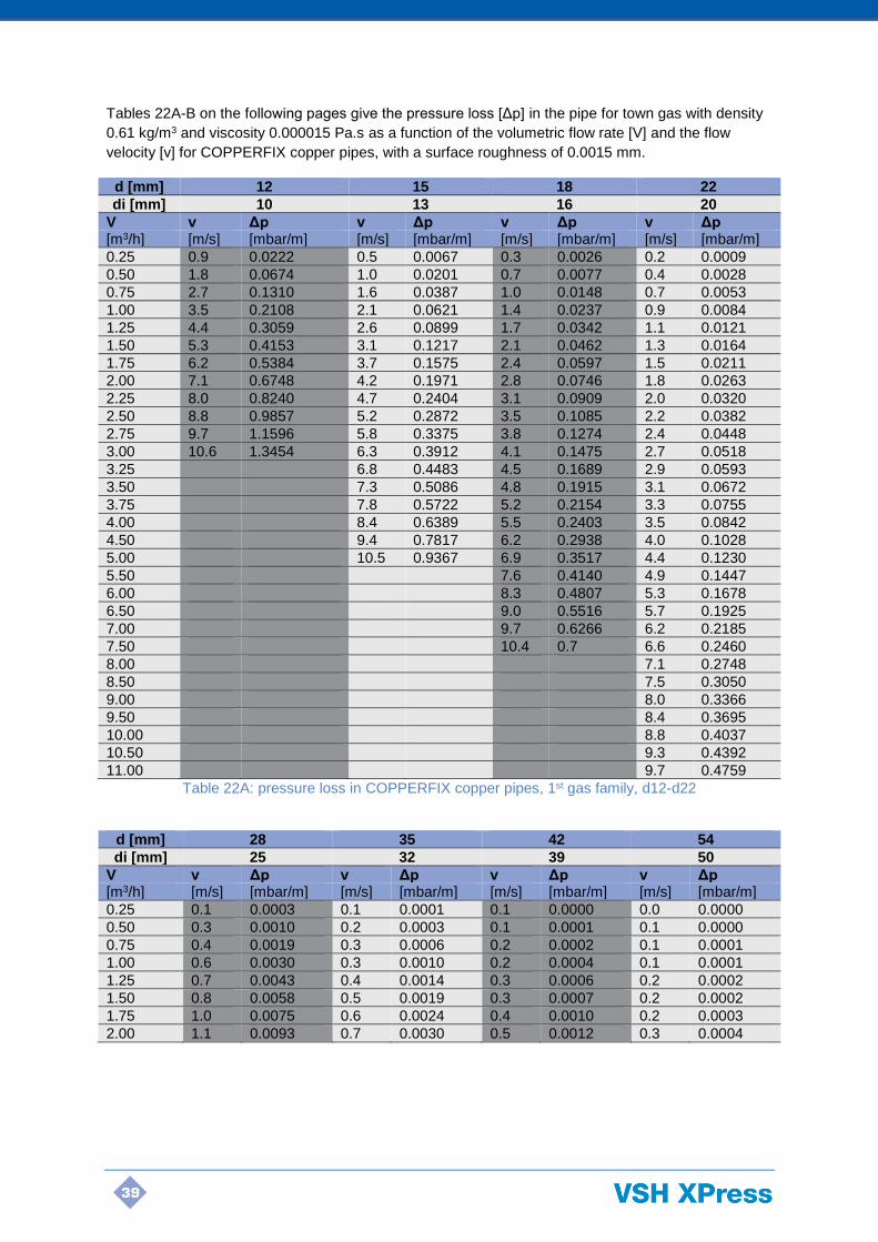
39
Tables 22A-B on the following pages give the pressure loss [Δp] in the pipe for town gas with density
0.61 kg/m3 and viscosity 0.000015 Pa.s as a function of the volumetric flow rate [V] and the flow
velocity [v] for COPPERFIX copper pipes, with a surface roughness of 0.0015 mm.
d [mm] 12 15 18 22
di [mm] 10 13 16 20
V v Δp v Δp v Δp v Δp [m3/h] [m/s] [mbar/m] [m/s] [mbar/m] [m/s] [mbar/m] [m/s] [mbar/m]
0.25 0.9 0.0222 0.5 0.0067 0.3 0.0026 0.2 0.0009
0.50 1.8 0.0674 1.0 0.0201 0.7 0.0077 0.4 0.0028
0.75 2.7 0.1310 1.6 0.0387 1.0 0.0148 0.7 0.0053
1.00 3.5 0.2108 2.1 0.0621 1.4 0.0237 0.9 0.0084
1.25 4.4 0.3059 2.6 0.0899 1.7 0.0342 1.1 0.0121
1.50 5.3 0.4153 3.1 0.1217 2.1 0.0462 1.3 0.0164
1.75 6.2 0.5384 3.7 0.1575 2.4 0.0597 1.5 0.0211
2.00 7.1 0.6748 4.2 0.1971 2.8 0.0746 1.8 0.0263
2.25 8.0 0.8240 4.7 0.2404 3.1 0.0909 2.0 0.0320
2.50 8.8 0.9857 5.2 0.2872 3.5 0.1085 2.2 0.0382
2.75 9.7 1.1596 5.8 0.3375 3.8 0.1274 2.4 0.0448
3.00 10.6 1.3454 6.3 0.3912 4.1 0.1475 2.7 0.0518
3.25 6.8 0.4483 4.5 0.1689 2.9 0.0593
3.50 7.3 0.5086 4.8 0.1915 3.1 0.0672
3.75 7.8 0.5722 5.2 0.2154 3.3 0.0755
4.00 8.4 0.6389 5.5 0.2403 3.5 0.0842
4.50 9.4 0.7817 6.2 0.2938 4.0 0.1028
5.00 10.5 0.9367 6.9 0.3517 4.4 0.1230
5.50 7.6 0.4140 4.9 0.1447
6.00 8.3 0.4807 5.3 0.1678
6.50 9.0 0.5516 5.7 0.1925
7.00 9.7 0.6266 6.2 0.2185
7.50 10.4 0.7 6.6 0.2460
8.00 7.1 0.2748
8.50 7.5 0.3050
9.00 8.0 0.3366
9.50 8.4 0.3695
10.00 8.8 0.4037
10.50 9.3 0.4392
11.00 9.7 0.4759
Table 22A: pressure loss in COPPERFIX copper pipes, 1st gas family, d12-d22
d [mm] 28 35 42 54
di [mm] 25 32 39 50
V v Δp v Δp v Δp v Δp [m3/h] [m/s] [mbar/m] [m/s] [mbar/m] [m/s] [mbar/m] [m/s] [mbar/m]
0.25 0.1 0.0003 0.1 0.0001 0.1 0.0000 0.0 0.0000
0.50 0.3 0.0010 0.2 0.0003 0.1 0.0001 0.1 0.0000
0.75 0.4 0.0019 0.3 0.0006 0.2 0.0002 0.1 0.0001
1.00 0.6 0.0030 0.3 0.0010 0.2 0.0004 0.1 0.0001
1.25 0.7 0.0043 0.4 0.0014 0.3 0.0006 0.2 0.0002
1.50 0.8 0.0058 0.5 0.0019 0.3 0.0007 0.2 0.0002
1.75 1.0 0.0075 0.6 0.0024 0.4 0.0010 0.2 0.0003
2.00 1.1 0.0093 0.7 0.0030 0.5 0.0012 0.3 0.0004
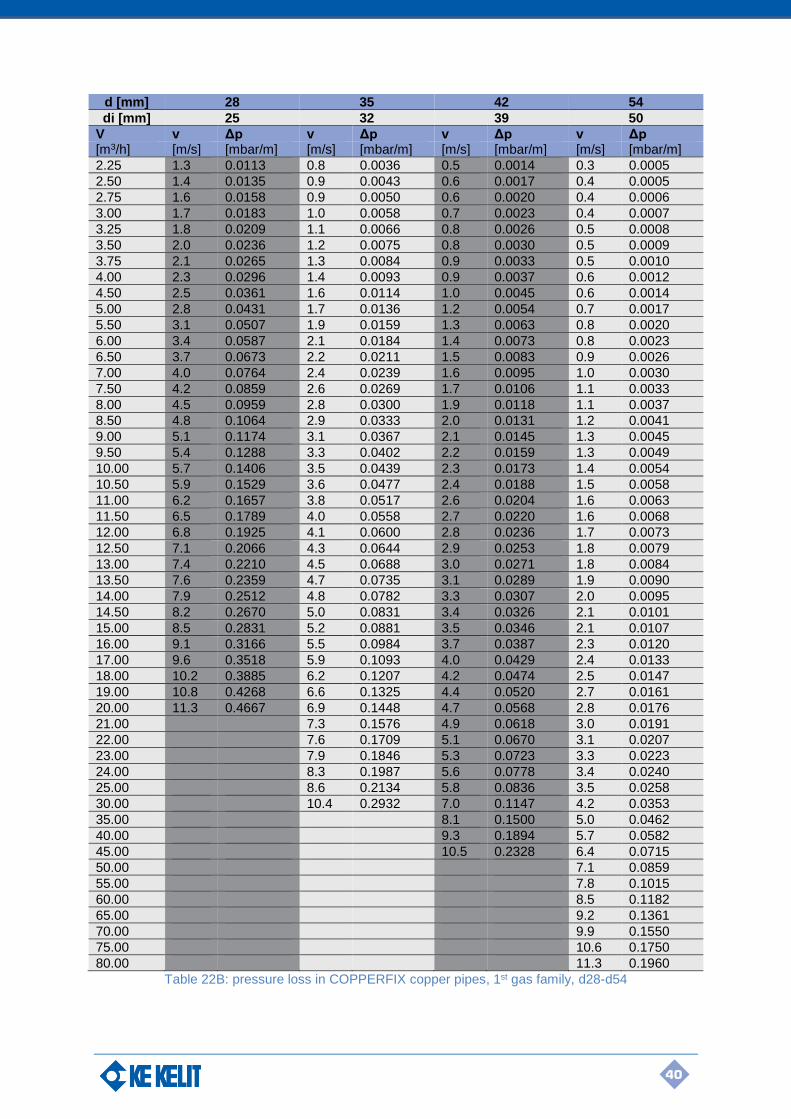
40
d [mm] 28 35 42 54
di [mm] 25 32 39 50
V v Δp v Δp v Δp v Δp [m3/h] [m/s] [mbar/m] [m/s] [mbar/m] [m/s] [mbar/m] [m/s] [mbar/m]
2.25 1.3 0.0113 0.8 0.0036 0.5 0.0014 0.3 0.0005
2.50 1.4 0.0135 0.9 0.0043 0.6 0.0017 0.4 0.0005
2.75 1.6 0.0158 0.9 0.0050 0.6 0.0020 0.4 0.0006
3.00 1.7 0.0183 1.0 0.0058 0.7 0.0023 0.4 0.0007
3.25 1.8 0.0209 1.1 0.0066 0.8 0.0026 0.5 0.0008
3.50 2.0 0.0236 1.2 0.0075 0.8 0.0030 0.5 0.0009
3.75 2.1 0.0265 1.3 0.0084 0.9 0.0033 0.5 0.0010
4.00 2.3 0.0296 1.4 0.0093 0.9 0.0037 0.6 0.0012
4.50 2.5 0.0361 1.6 0.0114 1.0 0.0045 0.6 0.0014
5.00 2.8 0.0431 1.7 0.0136 1.2 0.0054 0.7 0.0017
5.50 3.1 0.0507 1.9 0.0159 1.3 0.0063 0.8 0.0020
6.00 3.4 0.0587 2.1 0.0184 1.4 0.0073 0.8 0.0023
6.50 3.7 0.0673 2.2 0.0211 1.5 0.0083 0.9 0.0026
7.00 4.0 0.0764 2.4 0.0239 1.6 0.0095 1.0 0.0030
7.50 4.2 0.0859 2.6 0.0269 1.7 0.0106 1.1 0.0033
8.00 4.5 0.0959 2.8 0.0300 1.9 0.0118 1.1 0.0037
8.50 4.8 0.1064 2.9 0.0333 2.0 0.0131 1.2 0.0041
9.00 5.1 0.1174 3.1 0.0367 2.1 0.0145 1.3 0.0045
9.50 5.4 0.1288 3.3 0.0402 2.2 0.0159 1.3 0.0049
10.00 5.7 0.1406 3.5 0.0439 2.3 0.0173 1.4 0.0054
10.50 5.9 0.1529 3.6 0.0477 2.4 0.0188 1.5 0.0058
11.00 6.2 0.1657 3.8 0.0517 2.6 0.0204 1.6 0.0063
11.50 6.5 0.1789 4.0 0.0558 2.7 0.0220 1.6 0.0068
12.00 6.8 0.1925 4.1 0.0600 2.8 0.0236 1.7 0.0073
12.50 7.1 0.2066 4.3 0.0644 2.9 0.0253 1.8 0.0079
13.00 7.4 0.2210 4.5 0.0688 3.0 0.0271 1.8 0.0084
13.50 7.6 0.2359 4.7 0.0735 3.1 0.0289 1.9 0.0090
14.00 7.9 0.2512 4.8 0.0782 3.3 0.0307 2.0 0.0095
14.50 8.2 0.2670 5.0 0.0831 3.4 0.0326 2.1 0.0101
15.00 8.5 0.2831 5.2 0.0881 3.5 0.0346 2.1 0.0107
16.00 9.1 0.3166 5.5 0.0984 3.7 0.0387 2.3 0.0120
17.00 9.6 0.3518 5.9 0.1093 4.0 0.0429 2.4 0.0133
18.00 10.2 0.3885 6.2 0.1207 4.2 0.0474 2.5 0.0147
19.00 10.8 0.4268 6.6 0.1325 4.4 0.0520 2.7 0.0161
20.00 11.3 0.4667 6.9 0.1448 4.7 0.0568 2.8 0.0176
21.00 7.3 0.1576 4.9 0.0618 3.0 0.0191
22.00 7.6 0.1709 5.1 0.0670 3.1 0.0207
23.00 7.9 0.1846 5.3 0.0723 3.3 0.0223
24.00 8.3 0.1987 5.6 0.0778 3.4 0.0240
25.00 8.6 0.2134 5.8 0.0836 3.5 0.0258
30.00 10.4 0.2932 7.0 0.1147 4.2 0.0353
35.00 8.1 0.1500 5.0 0.0462
40.00 9.3 0.1894 5.7 0.0582
45.00 10.5 0.2328 6.4 0.0715
50.00 7.1 0.0859
55.00 7.8 0.1015
60.00 8.5 0.1182
65.00 9.2 0.1361
70.00 9.9 0.1550
75.00 10.6 0.1750
80.00 11.3 0.1960
Table 22B: pressure loss in COPPERFIX copper pipes, 1st gas family, d28-d54
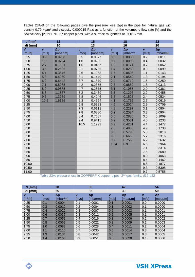
41
Tables 23A-B on the following pages give the pressure loss [Δp] in the pipe for natural gas with
density 0.79 kg/m3 and viscosity 0.000015 Pa.s as a function of the volumetric flow rate [V] and the
flow velocity [v] for EN1057 copper pipes, with a surface roughness of 0.0015 mm.
d [mm] 12 15 18 22 di [mm] 10 13 16 20
V v Δp v Δp v Δp v Δp [m3/h] [m/s] [mbar/m] [m/s] [mbar/m] [m/s] [mbar/m] [m/s] [mbar/m]
0.25 0.9 0.0258 0.5 0.0077 0.3 0.0030 0.2 0.0011
0.50 1.8 0.0794 1.0 0.0235 0.7 0.0090 0.4 0.0032
0.75 2.7 0.1551 1.6 0.0457 1.0 0.0174 0.7 0.0062
1.00 3.5 0.2506 2.1 0.0736 1.4 0.0280 0.9 0.0099
1.25 4.4 0.3646 2.6 0.1068 1.7 0.0405 1.1 0.0143
1.50 5.3 0.4960 3.1 0.1449 2.1 0.0549 1.3 0.0194
1.75 6.2 0.6442 3.7 0.1879 2.4 0.0710 1.5 0.0250
2.00 7.1 0.8085 4.2 0.2355 2.8 0.0889 1.8 0.0313
2.25 8.0 0.9885 4.7 0.2875 3.1 0.1085 2.0 0.0381
2.50 8.8 1.1837 5.2 0.3439 3.5 0.1296 2.2 0.0455
2.75 9.7 1.3939 5.8 0.4046 3.8 0.1523 2.4 0.0534
3.00 10.6 1.6186 6.3 0.4694 4.1 0.1766 2.7 0.0619
3.25 6.8 0.5383 4.5 0.2024 2.9 0.0709
3.50 7.3 0.6111 4.8 0.2297 3.1 0.0804
3.75 7.8 0.6880 5.2 0.2584 3.3 0.0904
4.00 8.4 0.7687 5.5 0.2885 3.5 0.1009
4.50 9.4 0.9415 6.2 0.3531 4.0 0.1233
5.00 10.5 1.1293 6.9 0.4231 4.4 0.1477
5.50 7.6 0.4986 4.9 0.1738
6.00 8.3 0.5793 5.3 0.2018
6.50 9.0 0.6653 5.7 0.2316
7.00 9.7 0.7563 6.2 0.2632
7.50 10.4 0.9 6.6 0.2964
8.00 7.1 0.3314
8.50 7.5 0.3680
9.00 8.0 0.4063
9.50 8.4 0.4462
10.00 8.8 0.4877
10.50 9.3 0.5308
11.00 9.7 0.5755
Table 23A: pressure loss in COPPERFIX copper pipes, 2nd gas family, d12-d22
d [mm] 28 35 42 54
di [mm] 25 32 39 50
V v Δp v Δp v Δp v Δp [m3/h] [m/s] [mbar/m] [m/s] [mbar/m] [m/s] [mbar/m] [m/s] [mbar/m]
0.25 0.1 0.0004 0.1 0.0001 0.1 0.0001 0.0 0.0000
0.50 0.3 0.0012 0.2 0.0004 0.1 0.0002 0.1 0.0000
0.75 0.4 0.0022 0.3 0.0007 0.2 0.0003 0.1 0.0001
1.00 0.6 0.0035 0.3 0.0011 0.2 0.0005 0.1 0.0001
1.25 0.7 0.0051 0.4 0.0016 0.3 0.0006 0.2 0.0002
1.50 0.8 0.0069 0.5 0.0022 0.3 0.0009 0.2 0.0003
1.75 1.0 0.0088 0.6 0.0028 0.4 0.0011 0.2 0.0004
2.00 1.1 0.0110 0.7 0.0035 0.5 0.0014 0.3 0.0004
2.25 1.3 0.0134 0.8 0.0042 0.5 0.0017 0.3 0.0005
2.50 1.4 0.0160 0.9 0.0051 0.6 0.0020 0.4 0.0006

42
d [mm] 28 35 42 54
di [mm] 25 32 39 50
V v Δp v Δp v Δp v Δp [m3/h] [m/s] [mbar/m] [m/s] [mbar/m] [m/s] [mbar/m] [m/s] [mbar/m]
2.75 1.6 0.0188 0.9 0.0059 0.6 0.0024 0.4 0.0007
3.00 1.7 0.0217 1.0 0.0069 0.7 0.0027 0.4 0.0009
3.25 1.8 0.0249 1.1 0.0078 0.8 0.0031 0.5 0.0010
3.50 2.0 0.0282 1.2 0.0089 0.8 0.0035 0.5 0.0011
3.75 2.1 0.0317 1.3 0.0100 0.9 0.0040 0.5 0.0012
4.00 2.3 0.0353 1.4 0.0111 0.9 0.0044 0.6 0.0014
4.50 2.5 0.0432 1.6 0.0135 1.0 0.0054 0.6 0.0017
5.00 2.8 0.0516 1.7 0.0162 1.2 0.0064 0.7 0.0020
5.50 3.1 0.0607 1.9 0.0190 1.3 0.0075 0.8 0.0023
6.00 3.4 0.0705 2.1 0.0221 1.4 0.0087 0.8 0.0027
6.50 3.7 0.0808 2.2 0.0253 1.5 0.0100 0.9 0.0031
7.00 4.0 0.0918 2.4 0.0287 1.6 0.0113 1.0 0.0035
7.50 4.2 0.1033 2.6 0.0323 1.7 0.0127 1.1 0.0040
8.00 4.5 0.1154 2.8 0.0360 1.9 0.0142 1.1 0.0044
8.50 4.8 0.1281 2.9 0.0400 2.0 0.0157 1.2 0.0049
9.00 5.1 0.1414 3.1 0.0441 2.1 0.0173 1.3 0.0054
9.50 5.4 0.1552 3.3 0.0484 2.2 0.0190 1.3 0.0059
10.00 5.7 0.1696 3.5 0.0528 2.3 0.0208 1.4 0.0064
10.50 5.9 0.1845 3.6 0.0574 2.4 0.0226 1.5 0.0070
11.00 6.2 0.1999 3.8 0.0622 2.6 0.0245 1.6 0.0076
11.50 6.5 0.2159 4.0 0.0672 2.7 0.0264 1.6 0.0082
12.00 6.8 0.2325 4.1 0.0723 2.8 0.0284 1.7 0.0088
12.50 7.1 0.2495 4.3 0.0776 2.9 0.0305 1.8 0.0094
13.00 7.4 0.2671 4.5 0.0830 3.0 0.0326 1.8 0.0101
13.50 7.6 0.2852 4.7 0.0886 3.1 0.0348 1.9 0.0108
14.00 7.9 0.3038 4.8 0.0943 3.3 0.0370 2.0 0.0115
14.50 8.2 0.3229 5.0 0.1003 3.4 0.0393 2.1 0.0122
15.00 8.5 0.3425 5.2 0.1063 3.5 0.0417 2.1 0.0129
16.00 9.1 0.3833 5.5 0.1189 3.7 0.0466 2.3 0.0144
17.00 9.6 0.4260 5.9 0.1321 4.0 0.0518 2.4 0.0160
18.00 10.2 0.4707 6.2 0.1459 4.2 0.0572 2.5 0.0177
19.00 10.8 0.5174 6.6 0.1603 4.4 0.0628 2.7 0.0194
20.00 11.3 0.5660 6.9 0.1752 4.7 0.0686 2.8 0.0212
21.00 7.3 0.1908 4.9 0.0747 3.0 0.0230
22.00 7.6 0.2069 5.1 0.0810 3.1 0.0250
23.00 7.9 0.2236 5.3 0.0875 3.3 0.0270
24.00 8.3 0.2409 5.6 0.0942 3.4 0.0290
25.00 8.6 0.2587 5.8 0.1011 3.5 0.0311
30.00 10.4 0.3560 7.0 0.1390 4.2 0.0427
35.00 8.1 0.1820 5.0 0.0559
40.00 9.3 0.2301 5.7 0.0706
45.00 10.5 0.2830 6.4 0.0868
50.00 7.1 0.1044
55.00 7.8 0.1234
60.00 8.5 0.1438
65.00 9.2 0.1655
70.00 9.9 0.1887
75.00 10.6 0.2131
80.00 11.3 0.2388
Table 23B: pressure loss in COPPERFIX copper pipes, 2nd gas family, d28-d54
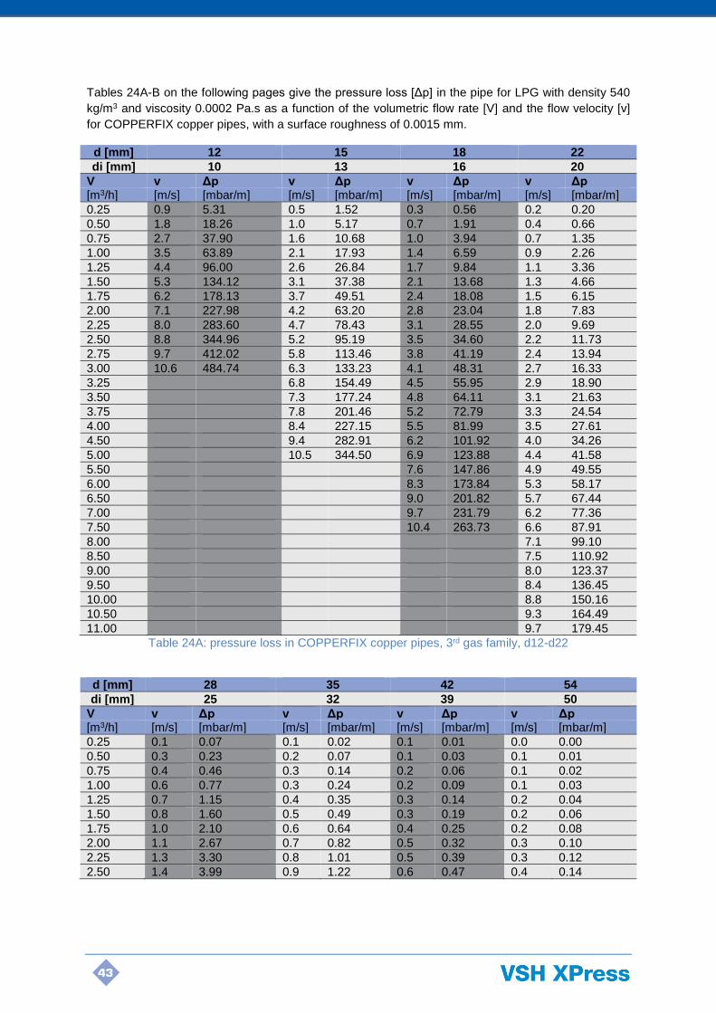
43
Tables 24A-B on the following pages give the pressure loss [Δp] in the pipe for LPG with density 540
kg/m3 and viscosity 0.0002 Pa.s as a function of the volumetric flow rate [V] and the flow velocity [v]
for COPPERFIX copper pipes, with a surface roughness of 0.0015 mm.
d [mm] 12 15 18 22
di [mm] 10 13 16 20
V v Δp v Δp v Δp v Δp [m3/h] [m/s] [mbar/m] [m/s] [mbar/m] [m/s] [mbar/m] [m/s] [mbar/m]
0.25 0.9 5.31 0.5 1.52 0.3 0.56 0.2 0.20
0.50 1.8 18.26 1.0 5.17 0.7 1.91 0.4 0.66
0.75 2.7 37.90 1.6 10.68 1.0 3.94 0.7 1.35
1.00 3.5 63.89 2.1 17.93 1.4 6.59 0.9 2.26
1.25 4.4 96.00 2.6 26.84 1.7 9.84 1.1 3.36
1.50 5.3 134.12 3.1 37.38 2.1 13.68 1.3 4.66
1.75 6.2 178.13 3.7 49.51 2.4 18.08 1.5 6.15
2.00 7.1 227.98 4.2 63.20 2.8 23.04 1.8 7.83
2.25 8.0 283.60 4.7 78.43 3.1 28.55 2.0 9.69
2.50 8.8 344.96 5.2 95.19 3.5 34.60 2.2 11.73
2.75 9.7 412.02 5.8 113.46 3.8 41.19 2.4 13.94
3.00 10.6 484.74 6.3 133.23 4.1 48.31 2.7 16.33
3.25 6.8 154.49 4.5 55.95 2.9 18.90
3.50 7.3 177.24 4.8 64.11 3.1 21.63
3.75 7.8 201.46 5.2 72.79 3.3 24.54
4.00 8.4 227.15 5.5 81.99 3.5 27.61
4.50 9.4 282.91 6.2 101.92 4.0 34.26
5.00 10.5 344.50 6.9 123.88 4.4 41.58
5.50 7.6 147.86 4.9 49.55
6.00 8.3 173.84 5.3 58.17
6.50 9.0 201.82 5.7 67.44
7.00 9.7 231.79 6.2 77.36
7.50 10.4 263.73 6.6 87.91
8.00 7.1 99.10
8.50 7.5 110.92
9.00 8.0 123.37
9.50 8.4 136.45
10.00 8.8 150.16
10.50 9.3 164.49
11.00 9.7 179.45
Table 24A: pressure loss in COPPERFIX copper pipes, 3rd gas family, d12-d22
d [mm] 28 35 42 54
di [mm] 25 32 39 50
V v Δp v Δp v Δp v Δp [m3/h] [m/s] [mbar/m] [m/s] [mbar/m] [m/s] [mbar/m] [m/s] [mbar/m]
0.25 0.1 0.07 0.1 0.02 0.1 0.01 0.0 0.00
0.50 0.3 0.23 0.2 0.07 0.1 0.03 0.1 0.01
0.75 0.4 0.46 0.3 0.14 0.2 0.06 0.1 0.02
1.00 0.6 0.77 0.3 0.24 0.2 0.09 0.1 0.03
1.25 0.7 1.15 0.4 0.35 0.3 0.14 0.2 0.04
1.50 0.8 1.60 0.5 0.49 0.3 0.19 0.2 0.06
1.75 1.0 2.10 0.6 0.64 0.4 0.25 0.2 0.08
2.00 1.1 2.67 0.7 0.82 0.5 0.32 0.3 0.10
2.25 1.3 3.30 0.8 1.01 0.5 0.39 0.3 0.12
2.50 1.4 3.99 0.9 1.22 0.6 0.47 0.4 0.14
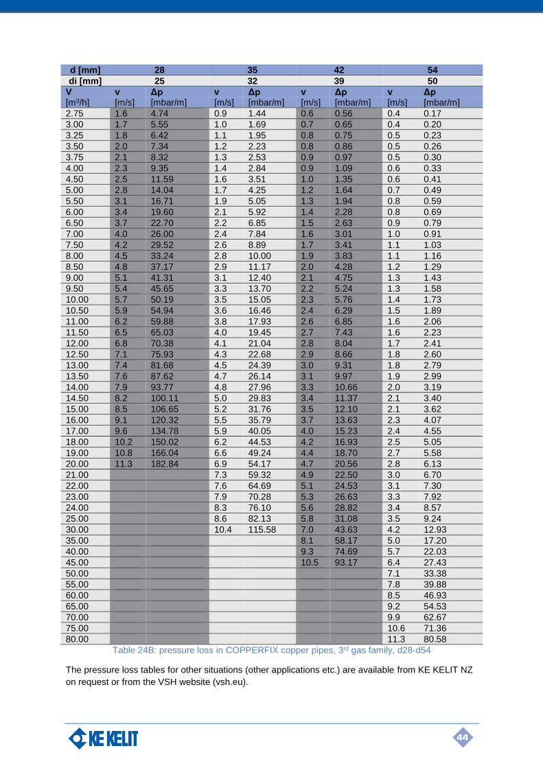
44
d [mm] 28 35 42 54
di [mm] 25 32 39 50
V v Δp v Δp v Δp v Δp [m3/h] [m/s] [mbar/m] [m/s] [mbar/m] [m/s] [mbar/m] [m/s] [mbar/m]
2.75 1.6 4.74 0.9 1.44 0.6 0.56 0.4 0.17
3.00 1.7 5.55 1.0 1.69 0.7 0.65 0.4 0.20
3.25 1.8 6.42 1.1 1.95 0.8 0.75 0.5 0.23
3.50 2.0 7.34 1.2 2.23 0.8 0.86 0.5 0.26
3.75 2.1 8.32 1.3 2.53 0.9 0.97 0.5 0.30
4.00 2.3 9.35 1.4 2.84 0.9 1.09 0.6 0.33
4.50 2.5 11.59 1.6 3.51 1.0 1.35 0.6 0.41
5.00 2.8 14.04 1.7 4.25 1.2 1.64 0.7 0.49
5.50 3.1 16.71 1.9 5.05 1.3 1.94 0.8 0.59
6.00 3.4 19.60 2.1 5.92 1.4 2.28 0.8 0.69
6.50 3.7 22.70 2.2 6.85 1.5 2.63 0.9 0.79
7.00 4.0 26.00 2.4 7.84 1.6 3.01 1.0 0.91
7.50 4.2 29.52 2.6 8.89 1.7 3.41 1.1 1.03
8.00 4.5 33.24 2.8 10.00 1.9 3.83 1.1 1.16
8.50 4.8 37.17 2.9 11.17 2.0 4.28 1.2 1.29
9.00 5.1 41.31 3.1 12.40 2.1 4.75 1.3 1.43
9.50 5.4 45.65 3.3 13.70 2.2 5.24 1.3 1.58
10.00 5.7 50.19 3.5 15.05 2.3 5.76 1.4 1.73
10.50 5.9 54.94 3.6 16.46 2.4 6.29 1.5 1.89
11.00 6.2 59.88 3.8 17.93 2.6 6.85 1.6 2.06
11.50 6.5 65.03 4.0 19.45 2.7 7.43 1.6 2.23
12.00 6.8 70.38 4.1 21.04 2.8 8.04 1.7 2.41
12.50 7.1 75.93 4.3 22.68 2.9 8.66 1.8 2.60
13.00 7.4 81.68 4.5 24.39 3.0 9.31 1.8 2.79
13.50 7.6 87.62 4.7 26.14 3.1 9.97 1.9 2.99
14.00 7.9 93.77 4.8 27.96 3.3 10.66 2.0 3.19
14.50 8.2 100.11 5.0 29.83 3.4 11.37 2.1 3.40
15.00 8.5 106.65 5.2 31.76 3.5 12.10 2.1 3.62
16.00 9.1 120.32 5.5 35.79 3.7 13.63 2.3 4.07
17.00 9.6 134.78 5.9 40.05 4.0 15.23 2.4 4.55
18.00 10.2 150.02 6.2 44.53 4.2 16.93 2.5 5.05
19.00 10.8 166.04 6.6 49.24 4.4 18.70 2.7 5.58
20.00 11.3 182.84 6.9 54.17 4.7 20.56 2.8 6.13
21.00 7.3 59.32 4.9 22.50 3.0 6.70
22.00 7.6 64.69 5.1 24.53 3.1 7.30
23.00 7.9 70.28 5.3 26.63 3.3 7.92
24.00 8.3 76.10 5.6 28.82 3.4 8.57
25.00 8.6 82.13 5.8 31.08 3.5 9.24
30.00 10.4 115.58 7.0 43.63 4.2 12.93
35.00 8.1 58.17 5.0 17.20
40.00 9.3 74.69 5.7 22.03
45.00 10.5 93.17 6.4 27.43
50.00 7.1 33.38
55.00 7.8 39.88
60.00 8.5 46.93
65.00 9.2 54.53
70.00 9.9 62.67
75.00 10.6 71.36
80.00 11.3 80.58
Table 24B: pressure loss in COPPERFIX copper pipes, 3rd gas family, d28-d54
The pressure loss tables for other situations (other applications etc.) are available from KE KELIT NZ
on request or from the VSH website (vsh.eu).
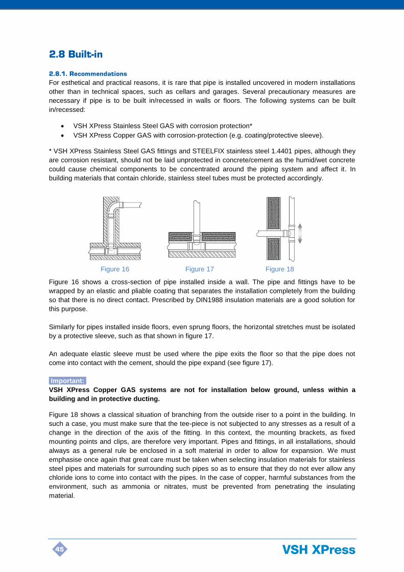
45
2.8 Built-in
2.8.1. Recommendations
For esthetical and practical reasons, it is rare that pipe is installed uncovered in modern installations
other than in technical spaces, such as cellars and garages. Several precautionary measures are
necessary if pipe is to be built in/recessed in walls or floors. The following systems can be built
in/recessed:
• VSH XPress Stainless Steel GAS with corrosion protection*
• VSH XPress Copper GAS with corrosion-protection (e.g. coating/protective sleeve).
* VSH XPress Stainless Steel GAS fittings and STEELFIX stainless steel 1.4401 pipes, although they
are corrosion resistant, should not be laid unprotected in concrete/cement as the humid/wet concrete
could cause chemical components to be concentrated around the piping system and affect it. In
building materials that contain chloride, stainless steel tubes must be protected accordingly.
Figure 16 shows a cross-section of pipe installed inside a wall. The pipe and fittings have to be
wrapped by an elastic and pliable coating that separates the installation completely from the building
so that there is no direct contact. Prescribed by DIN1988 insulation materials are a good solution for
this purpose.
Similarly for pipes installed inside floors, even sprung floors, the horizontal stretches must be isolated
by a protective sleeve, such as that shown in figure 17.
An adequate elastic sleeve must be used where the pipe exits the floor so that the pipe does not
come into contact with the cement, should the pipe expand (see figure 17).
Important:
VSH XPress Copper GAS systems are not for installation below ground, unless within a
building and in protective ducting.
Figure 18 shows a classical situation of branching from the outside riser to a point in the building. In
such a case, you must make sure that the tee-piece is not subjected to any stresses as a result of a
change in the direction of the axis of the fitting. In this context, the mounting brackets, as fixed
mounting points and clips, are therefore very important. Pipes and fittings, in all installations, should
always as a general rule be enclosed in a soft material in order to allow for expansion. We must
emphasise once again that great care must be taken when selecting insulation materials for stainless
steel pipes and materials for surrounding such pipes so as to ensure that they do not ever allow any
chloride ions to come into contact with the pipes. In the case of copper, harmful substances from the
environment, such as ammonia or nitrates, must be prevented from penetrating the insulating
material.
Figure 16 Figure 17 Figure 18

46
2.8.2 Mounting pipe
Ø pipe diameter [mm] Max. distance [m]
15 x 1.0 1.25
18 x 1.0 1.50
22 x 1.2 2.00
28 x 1.2 2.25
35 x 1.5 2.75
42 x 1.5 3.00
54 x 1.5 3.50
64 x 1.5 4.25
66.7 x 1.5 4.25
76.1 x 2.0 4.25
88.9 x 2.0 4.75
108 x 2.0 5.00
Table 25: distances between mounting brackets in accordance with en 806, part 4
Observance of the above distances between attachment points is not sufficient in itself. These
mounting distances are for guidance only. Please observe the local standards and requirements
which always take precedence. Heat expansion also needs to be appropriately compensated for in
horizontal stretches and, therefore, the distances above may need to be adjusted.
When securing the pipe, the following must be kept in mind: the load-bearing capacity of the mounting
brackets must correspond to the weight of the pipelines (including their contents) and also withstand
expansion and torsion forces. Mounting brackets, such as fixed mounting points and clips, must
therefore be correctly placed and assembled.
Attachment points may only be fitted onto straight pipe sections. Mounting directly onto fittings is not
allowed.
2.8.3 Pressure test
As soon as a piping system has been installed, it must be checked for leaks before being covered up
and concealed. With gas installations, the pressure test can be carried out with air, the gas for which
the system is designed, or an inert gas (unless the pipework exceeds 30L). Oxygen cannot be used
as a substitute for air. The test medium and the results of the pressure test must be documented in a
so-called pressure test report. If the internal pipework volume exceeds 30L, a specific written testing
procedure is required in the certified design for the gas installation (or part installation). For safety
reasons, the maximum test pressure with air or inert gases is set at 3 bar.
Important:
VSH and KE KELIT NZ stress that pressure testing of the piping system must be carried out in all
cases. Before being covered up, insulated, painted or walled in, a piping system must first undergo
pressure testing in order to be certain that there are no leaks. Pressure tests must always be
performed in accordance with local regulations.
Pressure test for gas systems
Important:
The pressure test for natural gas and liquid gas systems must be performed in accordance with local
regulations. In New Zealand this involves multiple gas tightness tests which are to be performed in
accordance with Appendix E of AS/NZS 5601.1:2013. This ensures that the piping system will
withstand a foreseeable pressure. The procedure for testing newly installed or altered pipework
includes pressurising the pipework to 1.5 times the operating pressure (or 7 kPa, whichever is
greater), allowing the temperature to stabilise for 2 minutes, and then monitoring the subsequent
pressure loss over 5 minutes. The pipework is only considered gastight if no pressure loss is recorded
over the 5 minute test period. Additional pressure tests of the installation are required to confirm that

47
the overall system is gastight and safe. Further details are contained in the VSH XPress GAS
distributed by KE KELIT NZ Training Manual, and in Appendix E of AS/NZS 5601.1:2013.
2.8.4 Purging
Purging of all air (or inert gas) must be performed once the work is completed, prior to commissioning
or the use of any connected gas appliances. This must be carried out to avoid the possibility of an
explosive air and gas mixture forming in piping, appliances, or confined spaces. Further details of the
purging process are contained in the VSH XPress GAS distributed by KE KELIT NZ Training Manual.
Local regulations must always be observed.
Important:
Do not commence any purging operation until a purging area is defined, made safe and cleared of all
potential ignition sources.
2.9 Corrosion
There are different kinds of corrosion: chemical corrosion, electro-chemical corrosion, internal and
external local corrosion, stray current corrosion, etc. All these kinds of corrosion have very particular
chemical or mechanical causes. The following paragraphs provide some simple hints on how to avoid
such problems.
Stray currents
Corrosion by stray currents rarely occurs in practice and is immediately recognizable as it starts on
the outside of the pipe with a cone-shaped crater to the inside. Stray current corrosion requires a
direct current that turns the metal into an anode. The current, which in practice and despite insulation
measures penetrates into the earth and from there goes into other neighbouring metal structures,
such as a gas supply installation, runs through a particular stretch of the system before it returns to
earth again. In order to penetrate into the piping system, the earth current must have an entry point at
a spot where the normal protective cover of the pipe or connection is damaged or missing.
For this reason, metal pipelines must be earthed. Direct current installations are generally not used in
domestic households and no real problems occur with alternating current. Research over decades
has shown that problems by stray currents only occur sporadically and do not depend on the type of
metal.
2.9.1 Prevention of corrosion
Instructions will be found in the following paragraphs on how to prevent corrosion problems in the
most usual places.
A. External corrosion
A.1 General
There are few situations in which outer corrosion occurs in buildings. It is, however, possible in many
cases that installations are exposed for a longer period to undesired penetration of rain, humidity or
dampness and this can lead to problems. Responsibility for taking relevant measures rests, however,
with the user and the installer. Only suitable corrosion protection can offer permanent certainty
against corrosion. One way of doing so is to use “closed cell” insulation, which must be applied in a
guaranteed waterproof condition. Suitable primers - or metallic paints may offer minimal corrosion
protection. It is advisable to always use corrosion protection on the tubing in situations where
corrosion is likely to occur (damp room, crawl spaces, etc.).
A.2 Stainless steel
Outer corrosion can occur if STEELFIX stainless steel 1.4401 piping comes into contact with chlorine
gas, saltwater or brine or (oxygen-saturated) water with a high chlorine content. If there is the danger
48
of building materials coming into contact over a long period with highly chlorinated water, suitable
corrosion protection must be used.
A.3 Copper
Copper's high resistance to corrosion often renders corrosion-protection measures superfluous.
However, copper tubing must sometimes also be protected from the impact of outer corrosion, such
as sulphites, nitrites and ammonia.
Important:
VSH XPress Copper GAS systems are not for installation below ground, unless within a
building and in protective ducting. Gas pipes must be protected against corrosion in
accordance with local regulations.
B. Impact of application and processing
B.1 General
Corrosion may occur due to incorrectly designed installations and faulty applications. The following
points must be observed:
B.2 Stainless steel
Cutting stainless steel
Cutting through stainless steel pipe is not allowed due to the amount of heat developed.
Bending stainless steel pipes
Stainless steel pipes may not be bent warm. The heating of the stainless steel pipe alters the
structure of the material (sensitisation) and inter-crystalline corrosion can take place.
Connections
Welding of stainless steel pipe may cause pitting or ring corrosion. In the case of TIG welding of
stainless steel, discolouration occurs at the welding joints, which may lead to corrosion on contact
with salt water. This discolouration, mainly on the inside of the pipe, can only be removed by staining,
which is not practical with piping that has already been installed.
C. Effect of insulation
C.1 General
“Closed cell insulation” (sealed watertight) offers effective protection against corrosion. The
installation instructions of the supplier of the insulating material must always be followed carefully.
Remove dust, dirt, oil and water from the piping prior to insulating.
The different sections of the insulation material must be carefully joined, taking care that no moisture
or water can enter the material.
Also take care that the water barrier of the insulation material is not damaged during installation as
moisture could otherwise penetrate under the insulation material.
C.2 Insulating stainless steel
Insulating materials that release chloride ions in water or which could cause a local increase in
chloride ions are not permitted. The weight ratio of water-solution chloride ions in the thermal
insulation of the pipe may not exceed 0.05% (AS quality).
C.3 Insulating copper
Insulation materials for copper must be nitrate-free i.e. they may not contain more than 0.02% nitrate.
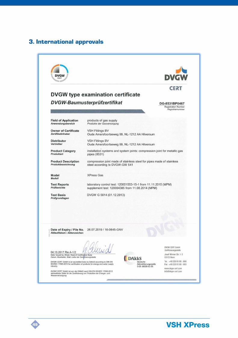
49
3. International approvals

50

51
52
53

54

55
4. Combined Press Connections
4. Combined press
connections

56
Minimum distance between pressings:
VSH XPress Stainless Steel GAS
DN d Tube length L-min
Min distance between fittings A-min
Insertion Depth es
12 15 50 10 20
15 18 50 10 20
20 22 52 10 21
25 28 56 10 23
32 35 62 10 26
40 42 80 20 30
50 54 90 20 35
65 76.1 165 55 55
80 88.9 191 65 63
100 108 234 80 77
VSH XPress Copper GAS
DN d Tube length L-min
Min distance between fittings A-min
Insertion Depth es
12 15 50 10 20
15 18 50 10 20
20 22 52 10 21
25 28 56 10 23
32 35 62 10 26
40 42 80 20 30
50 54 90 20 35
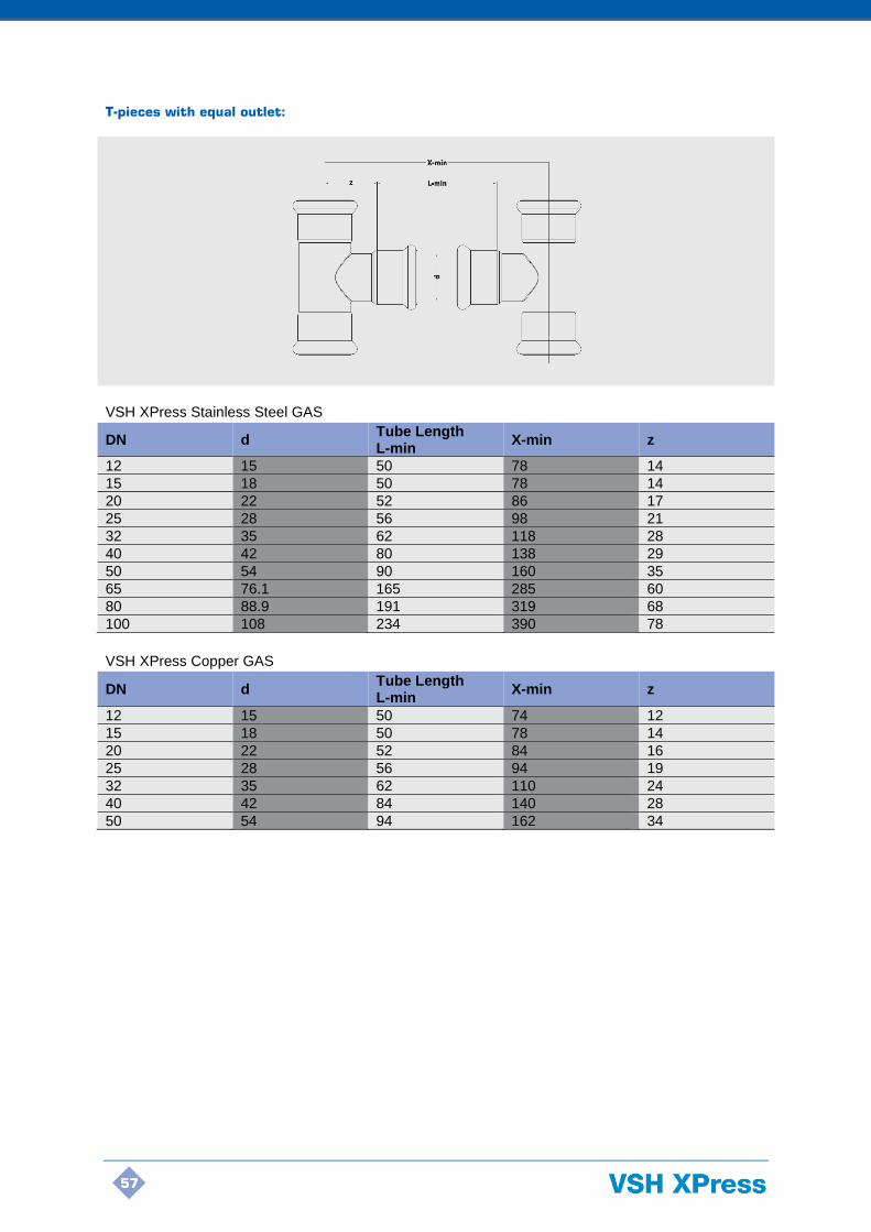
57
T-pieces with equal outlet:
VSH XPress Stainless Steel GAS
DN d Tube Length L-min
X-min z
12 15 50 78 14
15 18 50 78 14
20 22 52 86 17
25 28 56 98 21
32 35 62 118 28
40 42 80 138 29
50 54 90 160 35
65 76.1 165 285 60
80 88.9 191 319 68
100 108 234 390 78
VSH XPress Copper GAS
DN d Tube Length L-min
X-min z
12 15 50 74 12
15 18 50 78 14
20 22 52 84 16
25 28 56 94 19
32 35 62 110 24
40 42 84 140 28
50 54 94 162 34

58
Minimum distance between 2 t-pieces with equal and reduced outlet:
VSH XPress Stainless Steel GAS
DN d Tube Length L-min
X-min z
12 15 50 82 16
15 18 50 88 19
20 22 52 88 18
25 28 56 100 22
32 35 62 110 24
40 42 80 134 27
50 54 90 158 34
65 76.1 165 287 61
80 88.9 191 327 68
100 108 234 392 79
VSH XPress Copper GAS
DN d Tube Length L-min
X-min z
12 15 50 74 12
15 18 50 78 14
20 22 52 84 16
25 28 56 94 19
32 35 62 110 24
40 42 84 140 28
50 54 94 162 34
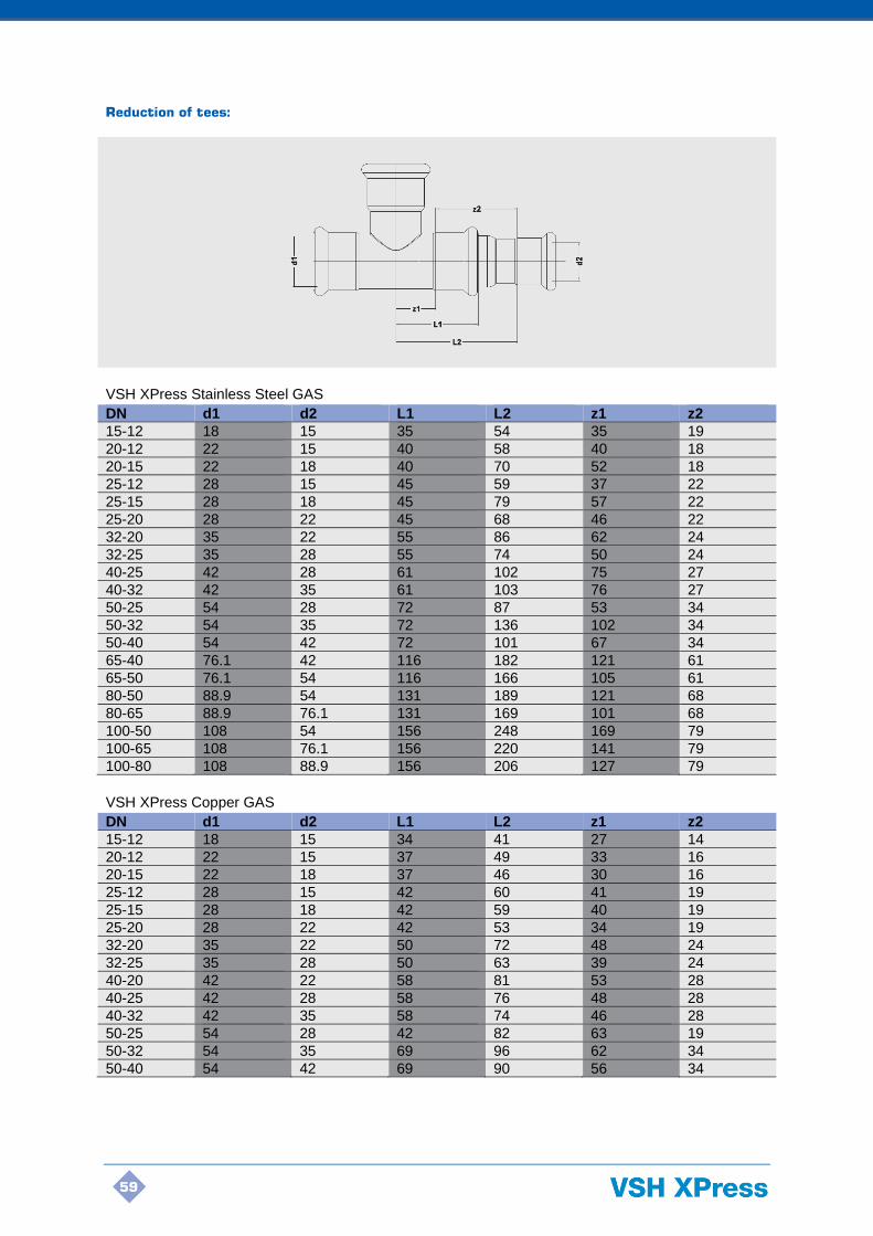
59
Reduction of tees:
VSH XPress Stainless Steel GAS
DN d1 d2 L1 L2 z1 z2
15-12 18 15 35 54 35 19
20-12 22 15 40 58 40 18
20-15 22 18 40 70 52 18
25-12 28 15 45 59 37 22
25-15 28 18 45 79 57 22
25-20 28 22 45 68 46 22
32-20 35 22 55 86 62 24
32-25 35 28 55 74 50 24
40-25 42 28 61 102 75 27
40-32 42 35 61 103 76 27
50-25 54 28 72 87 53 34
50-32 54 35 72 136 102 34
50-40 54 42 72 101 67 34
65-40 76.1 42 116 182 121 61
65-50 76.1 54 116 166 105 61
80-50 88.9 54 131 189 121 68
80-65 88.9 76.1 131 169 101 68
100-50 108 54 156 248 169 79
100-65 108 76.1 156 220 141 79
100-80 108 88.9 156 206 127 79
VSH XPress Copper GAS
DN d1 d2 L1 L2 z1 z2
15-12 18 15 34 41 27 14
20-12 22 15 37 49 33 16
20-15 22 18 37 46 30 16
25-12 28 15 42 60 41 19
25-15 28 18 42 59 40 19
25-20 28 22 42 53 34 19
32-20 35 22 50 72 48 24
32-25 35 28 50 63 39 24
40-20 42 22 58 81 53 28
40-25 42 28 58 76 48 28
40-32 42 35 58 74 46 28
50-25 54 28 42 82 63 19
50-32 54 35 69 96 62 34
50-40 54 42 69 90 56 34

60
Bend 45° (2 x press) on bend 45° (press x male):
VSH XPress Stainless Steel GAS
DN d a z1 z2 z3 b
12 15 45 16 77 16 45
15 18 44 17 78 17 44
20 22 52 21 94 21 52
25 28 62 27 116 27 62
32 35 69 32 133 32 69
40 42 88 45 178 45 88
50 54 105 51 207 51 105
65 76.1 113 43 199 43 113
80 88.9 127 49 225 49 127
100 108 152 61 274 61 152
VSH XPress Copper GAS
DN d a z1 z2 z3 b
12 15 32 8 48 8 32
15 18 34 9 52 9 34
20 22 40 12 63 11 40
25 28 45 16 75 14 45
32 35 54 18 89 17 54
40 42 65 21 107 21 65
50 54 77 27 131 27 77
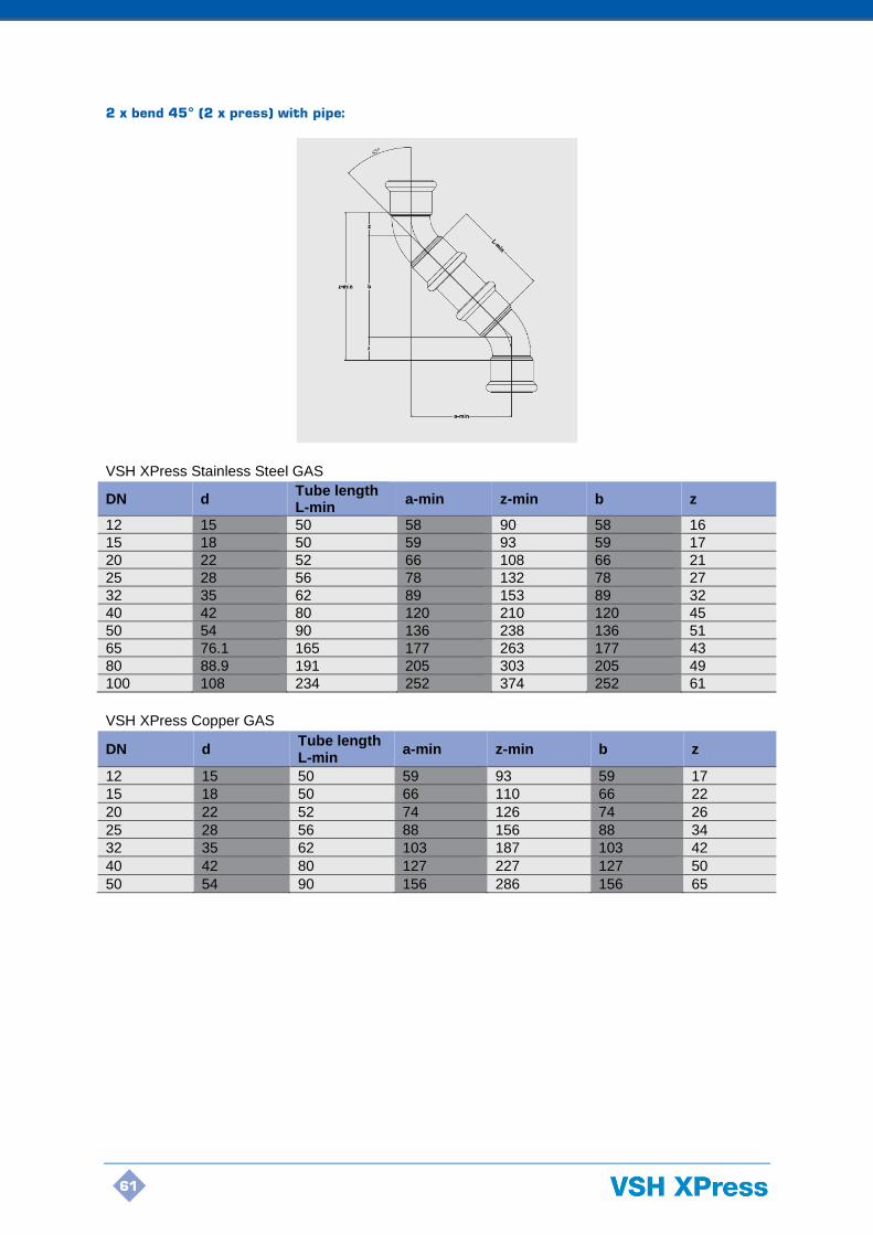
61
2 x bend 45° (2 x press) with pipe:
VSH XPress Stainless Steel GAS
DN d Tube length L-min
a-min z-min b z
12 15 50 58 90 58 16
15 18 50 59 93 59 17
20 22 52 66 108 66 21
25 28 56 78 132 78 27
32 35 62 89 153 89 32
40 42 80 120 210 120 45
50 54 90 136 238 136 51
65 76.1 165 177 263 177 43
80 88.9 191 205 303 205 49
100 108 234 252 374 252 61
VSH XPress Copper GAS
DN d Tube length L-min
a-min z-min b z
12 15 50 59 93 59 17
15 18 50 66 110 66 22
20 22 52 74 126 74 26
25 28 56 88 156 88 34
32 35 62 103 187 103 42
40 42 80 127 227 127 50
50 54 90 156 286 156 65

62
Bend 90° (2 x press) on bend 90° (press x male):
VSH XPress Stainless Steel GAS
DN d A h z1 z2
12 15 83 56 27 54
15 18 94 62 32 64
20 22 105 68 37 74
25 28 127 80 47 94
32 35 153 93 60 120
40 42 208 125 83 166
50 54 254 149 105 210
65 76.1 260 165 95 205
80 88.9 301 190 111 238
100 108 376 238 138 299
VSH XPress Copper GAS
DN d A h z1 z2
12 15 67 50 17 33
15 18 75 53 22 44
20 22 84 58 26 53
25 28 98 64 34 68
32 35 124 82 42 86
40 42 151 101 50 102
50 54 185 120 65 131

63
2 x bend 90° (2 x press) with pipe:
VSH XPress Stainless Steel GAS
DN d A-min L-min z1 z2
12 15 104 50 27 54
15 18 114 50 32 64
20 22 126 52 37 74
25 28 150 56 47 94
32 35 182 62 60 120
40 42 246 80 83 166
50 54 300 90 105 210
65 76.1 355 165 95 190
80 88.9 413 191 111 222
100 108 510 234 138 276
VSH XPress Copper GAS
DN d A-min L-min z1 z2
12 15 92 50 21 42
15 18 100 50 25 50
20 22 112 52 30 60
25 28 131 56 38 75
32 35 153 62 46 91
40 42 193 80 57 113
50 54 230 90 70 140

64
Bend 90° (2 x press) on bend pipe 90° (long side):
VSH XPress Stainless Steel GAS
DN Outside Ø A/A-min Z1 h2/h2-min Z2 h1 h1-min
12 15 147 27 120 97 70 50
15 18 152 32 120 102 70 50
20 22 157 37 120 109 72 51
25 28 167 47 120 129 82 59
32 35 260 60 200 180 120 94
40 42 333 83 250 233 150 120
50 54 405 105 300 305 200 165
VSH XPress Copper GAS
DN Outside Ø A/A-min Z1 h2/h2-min Z2 h1 h1-min
12 15 137 17 120 87 70 50
15 18 142 22 120 92 70 50
20 22 146 26 120 96 70 49
25 28 154 34 120 114 80 57

65
Bend 90° (2 x press) on bend pipe 90° (short side):
VSH XPress Stainless Steel GAS
DN d A/A-min z1 h2/h2-min z2 h1 h1-min
12 15 97 27 70 147 120 100
15 18 102 32 70 152 120 100
20 22 109 37 72 157 120 99
25 28 129 47 82 167 120 97
32 35 180 60 120 260 200 174
40 42 233 83 150 333 250 220
50 54 305 105 200 405 300 265
VSH XPress Copper GAS
DN d A/A-min z1 h2/h2-min z2 h1 h1-min
12 15 87 17 70 137 120 100
15 18 92 22 70 142 120 100
20 22 96 26 70 146 120 99
25 28 114 34 80 154 120 97

66
Bend 45° (press x male) on tee-lateral:
VSH XPress Stainless Steel GAS
DN d z3 z1 A = D z2
12 15 60 16 44 14
15 18 59 17 42 14
20 22 70 21 49 17
25 28 84 27 57 21
32 35 98 32 66 28
40 42 122 45 77 29
50 54 144 51 93 35
65 76.1 168 43 125 60
80 88.9 190 49 141 68
100 108 225 61 164 78
VSH XPress Copper GAS
DN d z3 z1 A = D z2
12 15 43 8 35 12
15 18 47 9 38 14
20 22 54 11 43 16
25 28 61 14 47 19
32 35 75 17 58 24
40 42 91 21 70 28
50 54 109 27 82 34

67
Bend 45° (2 x press) on tee-lateral with pipe:
VSH XPress Stainless Steel GAS
DN d z3 z1 A L-min z2 b-min
12 15 73 14 57 50 16 57
15 18 74 14 57 50 17 57
20 22 85 17 64 52 21 64
25 28 101 21 74 56 27 74
32 35 118 28 86 62 32 86
40 42 154 29 109 80 45 109
50 54 175 35 124 90 51 124
65 76.1 233 60 190 165 43 190
80 88.9 263 68 214 186 49 214
100 108 325 78 264 234 61 264
VSH XPress Copper GAS
DN d z3 z1 A L-min z2 b-min
12 15 73 12 56 50 17 56
15 18 83 14 61 50 22 61
20 22 92 16 66 52 26 66
25 28 111 19 77 56 34 77
32 35 133 24 91 62 42 91
40 42 162 28 112 80 50 112
50 54 199 34 134 90 65 134

68
Bend 90° (press x male) on tee-lateral:
VSH XPress Stainless Steel GAS
DN d M/M-min z1 h z2
12 15 70 27 56 14
15 18 76 32 62 14
20 22 85 37 68 17
25 28 101 47 80 21
32 35 121 60 93 28
40 42 154 83 125 29
50 54 184 105 149 35
65 76.1 225 95 165 60
80 88.9 258 112 190 68
100 108 316 138 238 78
VSH XPress Copper GAS
DN d M/M-min z1 h z2
12 15 62 16 50 12
15 18 67 22 53 14
20 22 74 27 58 16
25 28 83 34 64 19
32 35 106 44 82 24
40 42 129 52 101 28
50 54 154 66 120 34

69
Bend 90° (2 x press) on tee-lateral with pipe:
VSH XPress Stainless Steel GAS
DN d M-min L-min z1 z2
12 15 91 50 27 14
15 18 96 50 32 14
20 22 106 52 37 17
25 28 124 56 47 21
32 35 150 62 60 28
40 42 192 80 83 29
50 54 230 90 105 35
65 76.1 320 165 95 60
80 88.9 366 191 111 64
100 108 450 234 138 78
VSH XPress Copper GAS
DN d M-min L-min z1 z2
12 15 79 50 17 12
15 18 86 50 22 14
20 22 94 52 26 16
25 28 109 56 34 19
32 35 128 62 42 24
40 42 158 80 50 28
50 54 189 90 65 34
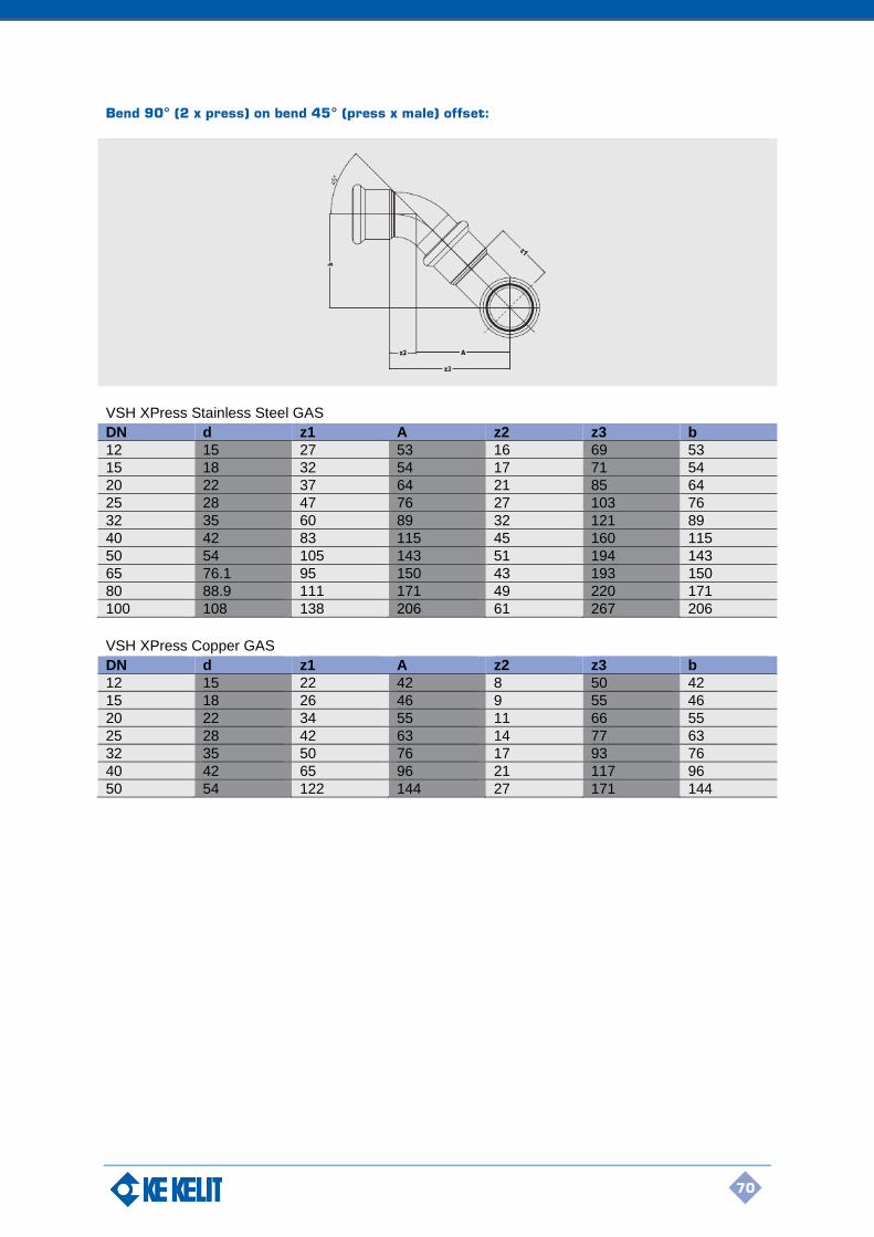
70
Bend 90° (2 x press) on bend 45° (press x male) offset:
VSH XPress Stainless Steel GAS
DN d z1 A z2 z3 b
12 15 27 53 16 69 53
15 18 32 54 17 71 54
20 22 37 64 21 85 64
25 28 47 76 27 103 76
32 35 60 89 32 121 89
40 42 83 115 45 160 115
50 54 105 143 51 194 143
65 76.1 95 150 43 193 150
80 88.9 111 171 49 220 171
100 108 138 206 61 267 206
VSH XPress Copper GAS
DN d z1 A z2 z3 b
12 15 22 42 8 50 42
15 18 26 46 9 55 46
20 22 34 55 11 66 55
25 28 42 63 14 77 63
32 35 50 76 17 93 76
40 42 65 96 21 117 96
50 54 122 144 27 171 144
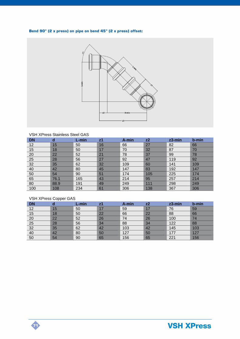
71
Bend 90° (2 x press) on pipe on bend 45° (2 x press) offset:
VSH XPress Stainless Steel GAS
DN d L-min z1 A-min z2 z3-min b-min
12 15 50 16 66 27 82 66
15 18 50 17 70 32 87 70
20 22 52 21 78 37 99 78
25 28 56 27 92 47 119 92
32 35 62 32 109 60 141 109
40 42 80 45 147 83 192 147
50 54 90 51 174 105 225 174
65 76.1 165 43 214 95 257 214
80 88.9 191 49 249 111 298 249
100 108 234 61 306 138 367 306
VSH XPress Copper GAS
DN d L-min z1 A-min z2 z3-min b-min
12 15 50 17 59 17 76 59
15 18 50 22 66 22 88 66
20 22 52 26 74 26 100 74
25 28 56 34 88 34 122 88
32 35 62 42 103 42 145 103
40 42 80 50 127 50 177 127
50 54 90 65 156 65 221 156
72
5. Product Range
5. Product range
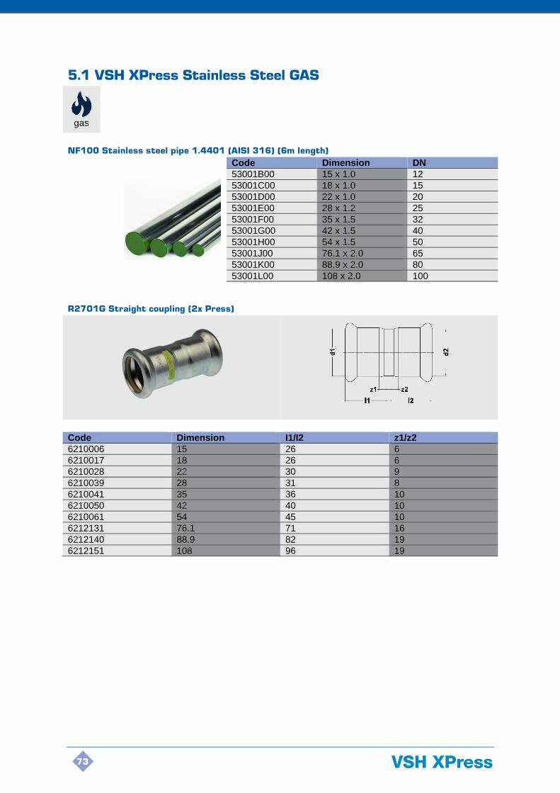
73
5.1 VSH XPress Stainless Steel GAS
gas
NF100 Stainless steel pipe 1.4401 (AISI 316) (6m length)
Code Dimension DN
53001B00 15 x 1.0 12
53001C00 18 x 1.0 15
53001D00 22 x 1.0 20
53001E00 28 x 1.2 25
53001F00 35 x 1.5 32
53001G00 42 x 1.5 40
53001H00 54 x 1.5 50
53001J00 76.1 x 2.0 65
53001K00 88.9 x 2.0 80
53001L00 108 x 2.0 100
R2701G Straight coupling (2x Press)
Code Dimension I1/I2 z1/z2
6210006 15 26 6
6210017 18 26 6
6210028 22 30 9
6210039 28 31 8
6210041 35 36 10
6210050 42 40 10
6210061 54 45 10
6212131 76.1 71 16
6212140 88.9 82 19
6212151 108 96 19
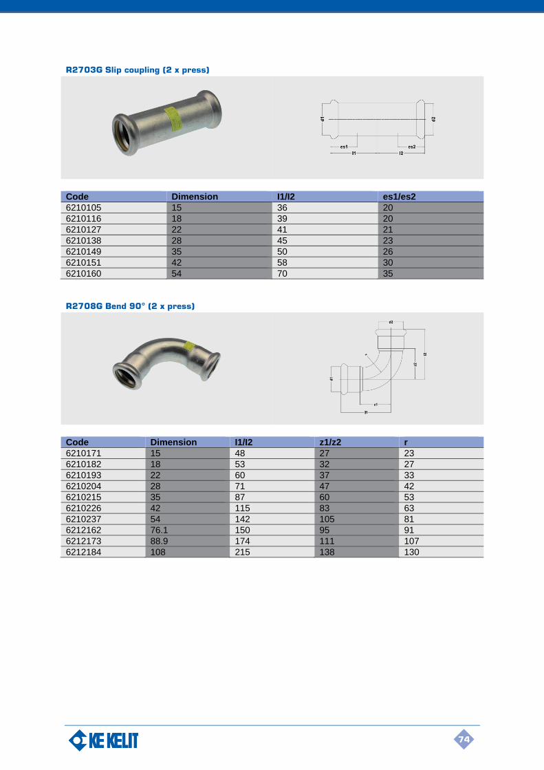
74
R2703G Slip coupling (2 x press)
Code Dimension I1/I2 es1/es2
6210105 15 36 20
6210116 18 39 20
6210127 22 41 21
6210138 28 45 23
6210149 35 50 26
6210151 42 58 30
6210160 54 70 35
R2708G Bend 90° (2 x press)
Code Dimension I1/I2 z1/z2 r
6210171 15 48 27 23
6210182 18 53 32 27
6210193 22 60 37 33
6210204 28 71 47 42
6210215 35 87 60 53
6210226 42 115 83 63
6210237 54 142 105 81
6212162 76.1 150 95 91
6212173 88.9 174 111 107
6212184 108 215 138 130
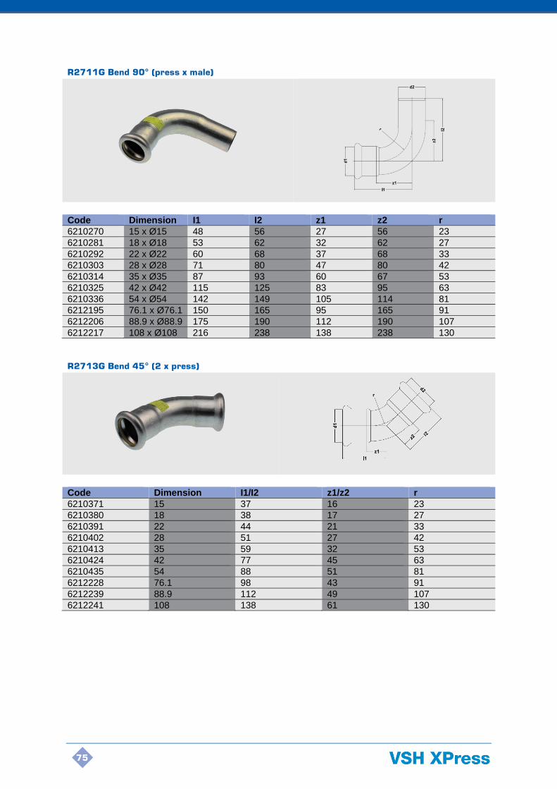
75
R2711G Bend 90° (press x male)
Code Dimension I1 I2 z1 z2 r
6210270 15 x Ø15 48 56 27 56 23
6210281 18 x Ø18 53 62 32 62 27
6210292 22 x Ø22 60 68 37 68 33
6210303 28 x Ø28 71 80 47 80 42
6210314 35 x Ø35 87 93 60 67 53
6210325 42 x Ø42 115 125 83 95 63
6210336 54 x Ø54 142 149 105 114 81
6212195 76.1 x Ø76.1 150 165 95 165 91
6212206 88.9 x Ø88.9 175 190 112 190 107
6212217 108 x Ø108 216 238 138 238 130
R2713G Bend 45° (2 x press)
Code Dimension I1/I2 z1/z2 r
6210371 15 37 16 23
6210380 18 38 17 27
6210391 22 44 21 33
6210402 28 51 27 42
6210413 35 59 32 53
6210424 42 77 45 63
6210435 54 88 51 81
6212228 76.1 98 43 91
6212239 88.9 112 49 107
6212241 108 138 61 130

76
R2712G Bend 45° (press x male)
Code Dimension I1 I2 z1 z2 r
6210479 15 x Ø15 37 48 16 28 23
6210481 18 x Ø18 38 45 17 25 27
6210490 22 x Ø22 44 53 21 32 33
6210501 28 x Ø28 51 60 27 37 42
6210512 35 x Ø35 59 66 32 40 53
6210523 42 x Ø42 77 80 45 50 63
6210534 54 x Ø54 88 97 51 62 81
6212250 76.1 x Ø76.1 98 117 43 62 91
6212261 88.9 x Ø88.9 112 131 49 68 107
6212272 108 x Ø108 138 154 61 77 130
R2714G Tee (3x press)
Code Dimension I1/I2 I3 z1/z3 z2
6210787 15 37 35 16 14
6210798 18 40 35 19 14
6210809 22 41 40 18 17
6210811 28 46 45 22 21
6210820 35 51 55 24 28
6210831 42 59 61 27 29
6210842 54 71 72 34 35
6212283 76.1 116 115 61 60
6212294 88.9 156 156 68 68
6212305 108 231 231 79 78

77
R2715G T-reduced (3 x press)
Code Dimension I1/I3 I2 z1/z3 z2
6210886 18 x 15 x 18 40 36 19 15
6210897 22 x 15 x 22 41 39 18 18
6210908 22 x 18 x 22 41 38 18 17
6210919 28 x 15 x 28 46 42 22 21
6210921 28 x 18 x 28 46 42 22 21
6210930 28 x 22 x 28 46 45 22 22
6210941 35 x 15 x 35 51 45 24 24
6210952 35 x 18 x 35 51 45 24 24
6210963 35 x 22 x 35 51 46 24 23
6210974 35 x 28 x 35 51 48 24 24
6210985 42 x 22 x 42 59 51 27 28
6210996 42 x 28 x 42 59 53 27 29
6211007 42 x 35 x 42 59 60 27 33
6211018 54 x 22 x 54 71 59 34 34
6211029 54 x 28 x 54 71 60 34 36
6211031 54 x 35 x 54 71 66 34 39
6211040 54 x 42 x 54 71 64 34 32
6212316 76.1 x 22 x 76.1 116 68 61 45
6212327 76.1 x 28 x 76.1 116 71 61 47
6212338 76.1 x 35 x 76.1 116 75 61 48
6212349 76.1 x 42 x 76.1 116 79 61 47
6212351 76.1 x 54 x 76.1 116 80 61 43
6212360 88.9 x 22 x 88.9 131 76 68 53
6212371 88.9 x 28 x 88.9 131 76 68 52
6212382 88.9 x 35 x 88.9 131 83 68 56
6212393 88.9 x 42 x 88.9 131 85 68 53
6212404 88.9 x 54 x 88.9 131 93 68 56
6212415 108 x 22 x 108 156 85 79 62
6212426 108 x 28 x 108 156 88 79 64
6212437 108 x 35 x 108 156 94 79 67
6212448 108 x 42 x 108 156 96 79 64
6212459 108 x 54 x 108 156 102 79 65

78
R2718G Tee (press x female thread x press)
Code Dimension I1/I3 I2 z1/z3 z2 slw2
6211051 15 x Rp1/2 x 15 37 37 16 25 24
6211062 18 x Rp1/2 x 18 40 39 19 27 24
6211073 18 x Rp3/4 x 18 40 43 19 30 30
6211084 22 x Rp1/2 x 22 41 41 18 29 24
6211095 22 x Rp3/4 x 22 41 41 18 28 30
6211106 28 x Rp1/2 x 28 46 44 22 32 24
6211117 28 x Rp3/4 x 28 46 45 22 32 30
6211128 35 x Rp1/2 x 35 51 48 24 36 24
6211139 35 x Rp3/4 x 35 51 48 24 35 30
6211141 42 x Rp1/2 x 42 59 46 27 34 24
6211150 54 x Rp1/2 x 54 71 69 34 47 30
6211161 54 x Rp3/4 x 54 71 55 34 43 24
6211172 54 x Rp2 x 54 71 58 34 45 65
6212461 76.1 x Rp3/4 x 76.1 116 81 61 59 30
6212470 76.1 x Rp2 x 76.1 116 68 61 55 65
6212481 88.9 x Rp3/4 x 88.9 131 88 68 66 30
6212492 88.9 x Rp2 x 88.9 131 87 68 74 65
6212503 108 x Rp3/4 x 108 156 86 79 73 30
6212514 108 x Rp2 x 108 156 98 79 76 65

79
R2707G Reducer (male x press)
Code Dimension I1 I2 z1 z2
6210591 Ø18 x 15 26 29 6 9
6210600 Ø22 x 15 26 34 6 13
6210611 Ø22 x 18 26 46 6 23
6210622 Ø28 x 15 25 32 5 11
6210633 Ø28 x 18 26 51 6 28
6210644 Ø28 x 22 29 38 8 12
6210655 Ø35 x 22 40 43 19 17
6210666 Ø35 x 28 30 43 7 17
6210677 Ø42 x 28 40 58 17 28
6210688 Ø42 x 35 40 59 17 24
6210699 Ø54 x 28 37 42 11 12
6210701 Ø54 x 35 50 78 24 43
6210710 Ø54 x 42 37 60 7 25
6212525 Ø76.1 x 42 50 101 20 46
6212536 Ø76.1 x 54 50 154 15 77
6212547 Ø88.9 x 54 50 90 15 35
6212558 Ø88.9 x 76.1 50 106 15 43
6212569 Ø108 x 54 65 131 10 54
6212571 Ø108 x 76.1 65 91 10 28
6212580 Ø108 x 88.9 78 112 15 35

80
R2705G Straight connector (press x male thread)
Dimension I1 z2 slw2
6211238 15 x R1/2 25 15 22
6211249 18 x R1/2 25 15 22
6211251 22 x R1/2 29 16 22
6211260 22 x R3/4 39 16 36
6211271 22 x R1 29 16 27
6211282 28 x R1 29 16 36
6211304 35 x R1 34 17 46
6211293 35 x R1 1/4 49 16 36
6211315 35 x R1 1/2 47 18 50
6211326 42 x R1 1/2 38 18 50
6211337 54 x R2 44 20 65
6212591 76.1 x R2 1/2 55 75 80
6212602 88.9 x R3 63 74 95
R2702G Straight connector (press x female thread)
Code Dimension I1 I2 z1 z2 slw2
6211348 15 x Rp1/2 27 27 10 10 22
6211359 18 x Rp1/2 26 26 9 9 22
6211361 22 x Rp1/2 28 28 10 10 22
6211370 22 x Rp3/4 35 35 16 16 27
6211381 22 x Rp1 26 26 9 9 36
6211392 28 x Rp1 31 31 11 11 36
6211414 35 x Rp1 36 36 14 14 46
6211403 35 x Rp1 1/4 41 41 19 19 50
6211425 42 x Rp1 1/2 37 37 13 13 50
6211447 54 x Rp2 53 53 26 26 65

81
R2728G Angle adapter 90° (press x male thread)
Code Dimension I1 z1 z2 slw2
6211458 15 x R1/2 53 32 14 22
6211469 18 x R1/2 51 30 14 22
6211471 22 x R3/4 58 35 14 28
6211480 28 x R1 63 39 15 36
6211491 35 x R1 1/4 71 44 13 46
R2709G Angle adapter 90° (press x female thread)
Code Dimension I1 I2 z1 z2 slw2
6211502 15 x Rp1/2 53 36 32 24 24
6211513 18 x Rp1/2 52 39 31 27 24
6211524 22 x Rp3/4 57 46 34 33 30
6211535 28 x Rp1 71 54 47 38 38
6211546 35 x Rp1 1/4 72 62 45 45 46
R2741G Coupling with nut (press x female thread)
Code Dimension I1 I2 z1 z2 slw2
6211801 15 x G7/8 39 8 19 2 30
6211581 22 x G1 1/8 43 8 22 2 37
6211590 28 x G1 3/8 45 10 22 2 46
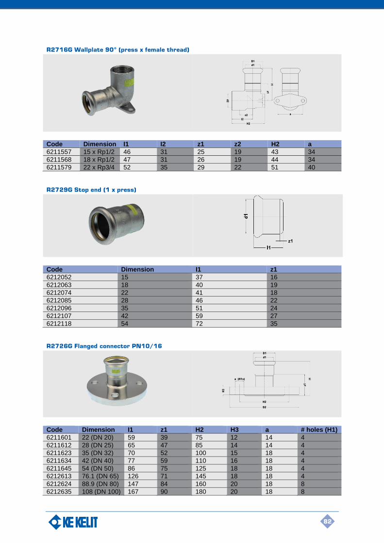
82
R2716G Wallplate 90° (press x female thread)
Code Dimension I1 I2 z1 z2 H2 a
6211557 15 x Rp1/2 46 31 25 19 43 34
6211568 18 x Rp1/2 47 31 26 19 44 34
6211579 22 x Rp3/4 52 35 29 22 51 40
R2729G Stop end (1 x press)
Code Dimension I1 z1
6212052 15 37 16
6212063 18 40 19
6212074 22 41 18
6212085 28 46 22
6212096 35 51 24
6212107 42 59 27
6212118 54 72 35
R2726G Flanged connector PN10/16
Code Dimension I1 z1 H2 H3 a # holes (H1)
6211601 22 (DN 20) 59 39 75 12 14 4
6211612 28 (DN 25) 65 47 85 14 14 4
6211623 35 (DN 32) 70 52 100 15 18 4
6211634 42 (DN 40) 77 59 110 16 18 4
6211645 54 (DN 50) 86 75 125 18 18 4
6212613 76.1 (DN 65) 126 71 145 18 18 4
6212624 88.9 (DN 80) 147 84 160 20 18 8
6212635 108 (DN 100) 167 90 180 20 18 8

83
R2742G Flat seal (yellow, NBR) for VSH XPress Stainless Steel GAS
Code Dimension
6211689 22
6211691 28
6211700 35
6211711 42
6211722 54
R2755G O-ring standard (yellow, HNBR) for VSH XPress Stainless Steel GAS
Code Dimension
6211911 15
6211920 18
6211931 22
6211942 28
6211953 35
6211964 42
6211975 54
6218102 76.1
6218113 88.9
6218124 108

84
5.2 VSH XPress Copper GAS
gas
COPPERFIX Copper pipe (R250/R290) (5.8m length)
Code Dimension DN
5620XB00 15 x 0.7 15
5620XC00 18 x 0.8 18
5620XD00 22 x 0.9 20
5620XE00 28 x 0.9 25
5630XF00 35 x 1.2 32
5630XG00 42 x 1.2 40
5630XH00 54 x 1.2 50
G7270 Straight coupling (2x Press)
Code Dimension I1/I2 z1/z2
4804437 15 22 2
4804448 18 22 2
4804459 22 23 2
4804461 28 25 2
4804470 35 28 2
4804481 42 36 4
4804492 54 42 5
G7270S Slip coupling (2x Press)
Code Dimension I1/I2 es1/es2
4804503 15 40 20
4804514 18 40 20
4804525 22 42 21
4804536 28 46 23
4804547 35 50 25
4804558 42 60 30
4804569 54 71 35

85
G7002A Bend 90° (2 x press)
Code Dimension I1/I2 z1/z2 r
4803832 15 38 17 14
4803843 18 42 22 22
4803854 22 47 26 26
4803865 28 56 34 34
4803876 35 68 42 42
4803887 42 80 50 50
4803898 54 100 65 65
G7001A Bend 90° (press x male)
Code Dimension I1 I2 z1 z2 r
4803766 15 x Ø15 36 50 16 30 18
4803777 18 x Ø18 42 53 22 33 22
4803788 22 x Ø22 47 58 27 38 26
4803799 28 x Ø28 58 64 34 40 34
4803801 35 x Ø35 69 82 44 57 42
4803810 42 x Ø42 81 101 52 72 50
4803821 54 x Ø54 100 120 66 86 65

86
G7041 Bend 45° (2 x press)
Code Dimension I1/I2 z1/z2 r
4803975 15 28 8 18
4803986 18 29 9 22
4803997 22 31 12 26
4804008 28 37 16 34
4804019 35 44 18 42
4804021 42 51 21 50
4804030 54 62 27 65
G7040 Bend 45° (press x male)
Code Dimension I1 I2 z1 z2 r
4803909 15 x Ø15 28 37 8 17 18
4803911 18 x Ø18 29 39 9 19 22
4803920 22 x Ø22 32 44 11 23 26
4803931 28 x Ø28 37 47 14 24 34
4803942 35 x Ø35 43 58 17 32 42
4803953 42 x Ø42 51 71 21 41 50
4803964 54 x Ø54 62 82 27 47 65

87
G7085 Crossover (2 x press)
Code Dimension I1/I2 z1/z2 H1
4804041 15 70 50 34
4804063 22 85 64 50
G7130 Tee (3 x press)
Code Dimension I1/I2/I3 z1/z2/z3
4804107 15 32 12
4804118 18 34 14
4804129 22 37 16
4804131 28 42 19
4804140 35 50 24
4804151 42 58 28
4804162 54 69 34

88
G7125 T-reduced (3 x press)
Code Dimension I1/I3 I2 z1/z3 z2
4804173 18 x 15 x 18 34 35 14 15
4804184 22 x 15 x 22 37 38 16 18
4804195 22 x 18 x 22 37 38 16 18
4804206 28 x 15 x 28 42 41 19 21
4804217 28 x 22 x 28 42 41 19 20
4804228 35 x 22 x 35 45 45 19 24
4804241 35 x 28 x 35 50 44 24 21
4804250 42 x 28 x 42 56 49 26 26
4804261 42 x 35 x 42 56 50 26 24
4804272 54 x 42 x 54 69 64 34 34
G7126 T-reduced (3 x press)
Code Dimension I1/I2 I3 z1/z2 z3
4804217 22 x 22 x 15 37 46 16 26
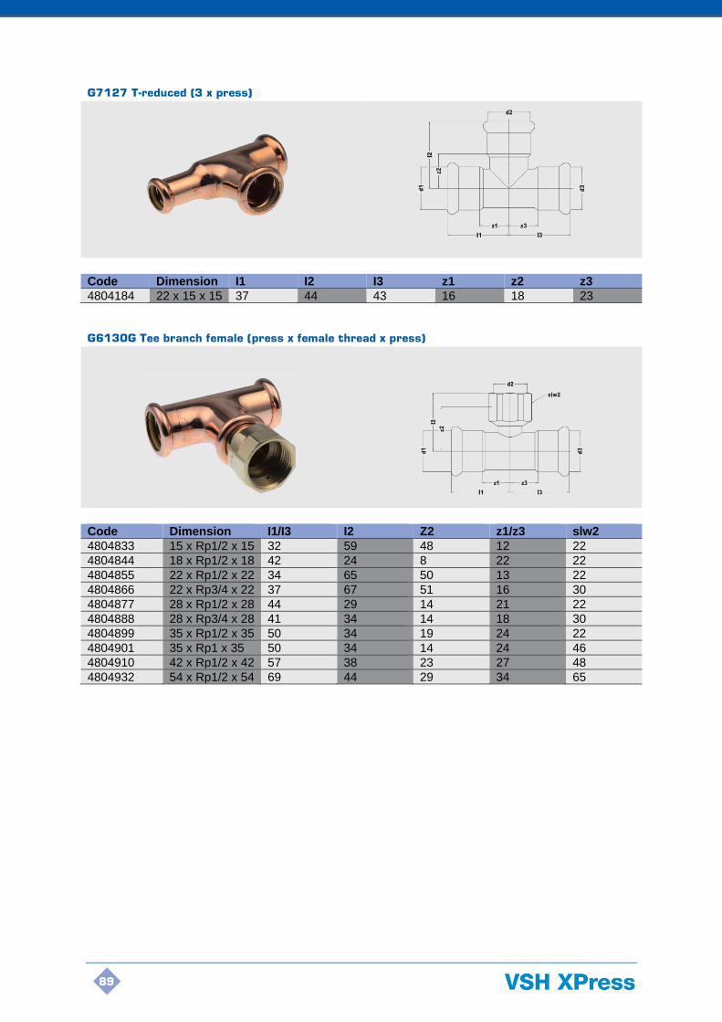
89
G7127 T-reduced (3 x press)
Code Dimension I1 I2 I3 z1 z2 z3
4804184 22 x 15 x 15 37 44 43 16 18 23
G6130G Tee branch female (press x female thread x press)
Code Dimension I1/I3 I2 Z2 z1/z3 slw2
4804833 15 x Rp1/2 x 15 32 59 48 12 22
4804844 18 x Rp1/2 x 18 42 24 8 22 22
4804855 22 x Rp1/2 x 22 34 65 50 13 22
4804866 22 x Rp3/4 x 22 37 67 51 16 30
4804877 28 x Rp1/2 x 28 44 29 14 21 22
4804888 28 x Rp3/4 x 28 41 34 14 18 30
4804899 35 x Rp1/2 x 35 50 34 19 24 22
4804901 35 x Rp1 x 35 50 34 14 24 46
4804910 42 x Rp1/2 x 42 57 38 23 27 48
4804932 54 x Rp1/2 x 54 69 44 29 34 65

90
G7243 Reducer (male x press)
Code Dimension I1 I2 z1 z2
4804305 Ø18 x 15 24 23 4 3
4804316 Ø22 x 15 24 28 4 7
4804327 Ø22 x 18 24 26 4 5
4804338 Ø28 x 15 25 37 4 14
4804349 Ø28 x 18 24 26 4 5
4804351 Ø28 x 22 25 30 4 7
4804360 Ø35 x 22 29 39 9 13
4804371 Ø35 x 28 28 35 5 9
4804382 Ø42 x 22 25 49 4 19
4804393 Ø42 x 28 27 44 4 14
4804404 Ø42 x 35 35 38 8 8
4804415 Ø54 x 35 35 53 9 18
4804426 Ø54 x 42 40 47 9 12
G6243G Straight connector (press x male thread)
Code Dimension I1 z2 slw2
4803414 15 x R1/2 20 17 21
4803425 15 x R3/4 20 19 25
4803436 18 x R1/2 20 17 25
4803447 18 x R3/4 20 19 25
4803458 22 x R1/2 21 17 30
4803469 22 x R3/4 21 19 30
4803471 22 x R1 21 21 32
4803480 28 x R3/4 23 20 36
4803491 28 x R1 23 10 36
4803502 28 x R1 1/4 23 13 40
4803513 35 x R1 26 22 41
4803524 35 x R1 1/4 26 27 41
4803535 42 x R1 1/4 30 28 51
4803546 42 x R1 1/2 30 28 51
4803557 54 x R2 35 28 57
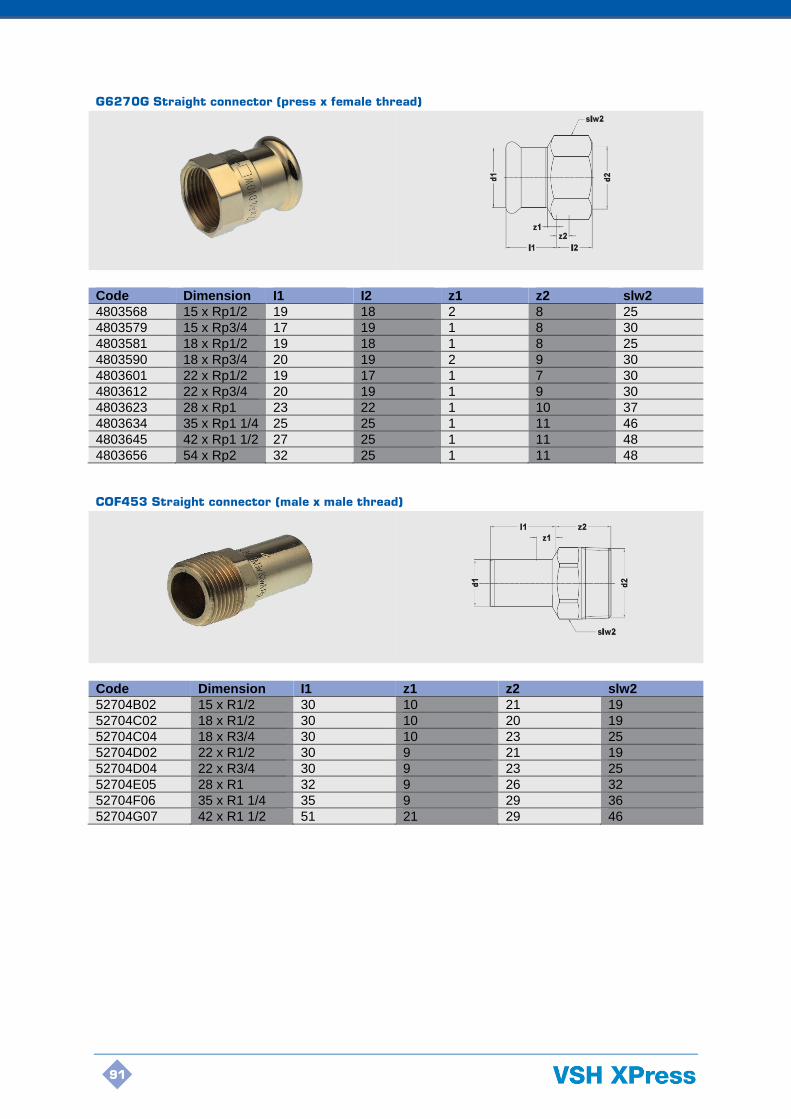
91
G6270G Straight connector (press x female thread)
Code Dimension I1 I2 z1 z2 slw2
4803568 15 x Rp1/2 19 18 2 8 25
4803579 15 x Rp3/4 17 19 1 8 30
4803581 18 x Rp1/2 19 18 1 8 25
4803590 18 x Rp3/4 20 19 2 9 30
4803601 22 x Rp1/2 19 17 1 7 30
4803612 22 x Rp3/4 20 19 1 9 30
4803623 28 x Rp1 23 22 1 10 37
4803634 35 x Rp1 1/4 25 25 1 11 46
4803645 42 x Rp1 1/2 27 25 1 11 48
4803656 54 x Rp2 32 25 1 11 48
COF453 Straight connector (male x male thread)
Code Dimension I1 z1 z2 slw2
52704B02 15 x R1/2 30 10 21 19
52704C02 18 x R1/2 30 10 20 19
52704C04 18 x R3/4 30 10 23 25
52704D02 22 x R1/2 30 9 21 19
52704D04 22 x R3/4 30 9 23 25
52704E05 28 x R1 32 9 26 32
52704F06 35 x R1 1/4 35 9 29 36
52704G07 42 x R1 1/2 51 21 29 46
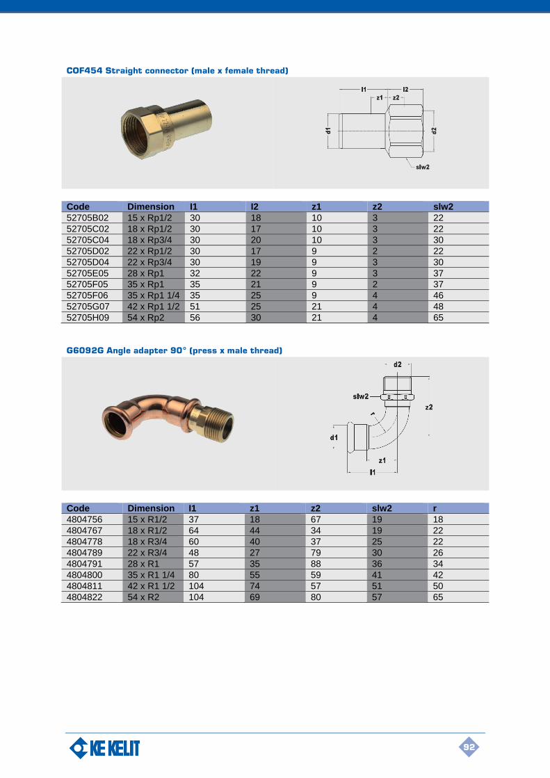
92
COF454 Straight connector (male x female thread)
Code Dimension I1 I2 z1 z2 slw2
52705B02 15 x Rp1/2 30 18 10 3 22
52705C02 18 x Rp1/2 30 17 10 3 22
52705C04 18 x Rp3/4 30 20 10 3 30
52705D02 22 x Rp1/2 30 17 9 2 22
52705D04 22 x Rp3/4 30 19 9 3 30
52705E05 28 x Rp1 32 22 9 3 37
52705F05 35 x Rp1 35 21 9 2 37
52705F06 35 x Rp1 1/4 35 25 9 4 46
52705G07 42 x Rp1 1/2 51 25 21 4 48
52705H09 54 x Rp2 56 30 21 4 65
G6092G Angle adapter 90° (press x male thread)
Code Dimension I1 z1 z2 slw2 r
4804756 15 x R1/2 37 18 67 19 18
4804767 18 x R1/2 64 44 34 19 22
4804778 18 x R3/4 60 40 37 25 22
4804789 22 x R3/4 48 27 79 30 26
4804791 28 x R1 57 35 88 36 34
4804800 35 x R1 1/4 80 55 59 41 42
4804811 42 x R1 1/2 104 74 57 51 50
4804822 54 x R2 104 69 80 57 65
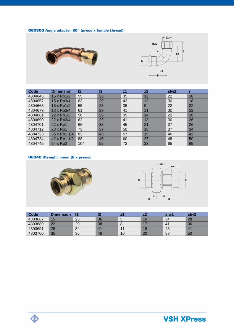
93
G6090G Angle adapter 90° (press x female thread)
Code Dimension I1 I2 z1 z2 slw2 r
4804646 15 x Rp1/2 55 26 35 12 22 18
4804657 15 x Rp3/4 63 29 43 12 30 18
4804668 18 x Rp1/2 55 25 35 9 22 22
4804679 18 x Rp3/4 61 29 41 11 30 22
4804681 22 x Rp1/2 56 25 35 14 22 26
4804690 22 x Rp3/4 62 29 41 13 30 26
4804701 22 x Rp1 66 38 45 21 37 26
4804712 28 x Rp1 73 37 50 18 37 34
4804723 35 x Rp1 1/4 83 43 57 19 46 42
4804734 42 x Rp1 1/2 88 46 60 27 48 50
4804745 54 x Rp2 104 55 72 33 65 65
G6340 Straight union (2 x press)
Code Dimension I1 I2 z1 z2 slw1 slw2
4803667 15 25 36 5 16 34 28
4803689 22 29 38 8 17 41 36
4803691 28 34 41 11 18 48 41
4803700 35 36 46 10 20 58 50
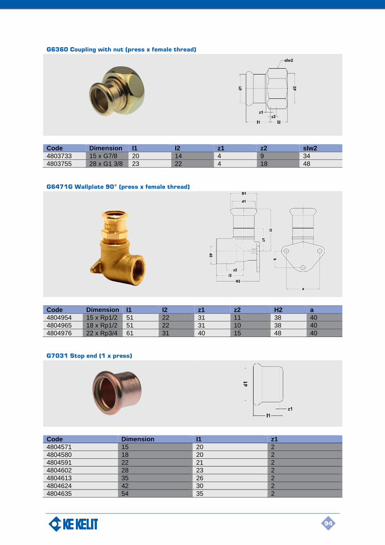
94
G6360 Coupling with nut (press x female thread)
Code Dimension I1 I2 z1 z2 slw2
4803733 15 x G7/8 20 14 4 9 34
4803755 28 x G1 3/8 23 22 4 18 48
G6471G Wallplate 90° (press x female thread)
Code Dimension I1 I2 z1 z2 H2 a
4804954 15 x Rp1/2 51 22 31 11 38 40
4804965 18 x Rp1/2 51 22 31 10 38 40
4804976 22 x Rp3/4 61 31 40 15 48 40
G7031 Stop end (1 x press)
Code Dimension I1 z1
4804571 15 20 2
4804580 18 20 2
4804591 22 21 2
4804602 28 23 2
4804613 35 26 2
4804624 42 30 2
4804635 54 35 2

95
G7999 O-ring standard (yellow, NBR) for VSH XPress Copper GAS
Code Dimension
4805108 15
4805119 18
4805121 22
4805130 28
4805141 35
4805152 42
4805163 54
96
6. XPress GAS Tools and Accessories
6. VSH XPress GAS
tools and accessories
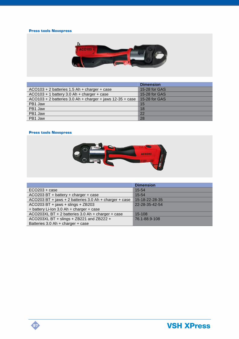
97
Press tools Novopress
Dimension
ACO103 + 2 batteries 1.5 Ah + charger + case 15-28 for GAS
ACO103 + 1 battery 3.0 Ah + charger + case 15-28 for GAS
ACO103 + 2 batteries 3.0 Ah + charger + jaws 12-35 + case 15-28 for GAS
PB1 Jaw 15
PB1 Jaw 18
PB1 Jaw 22
PB1 Jaw 28
Press tools Novopress
Dimension
ECO203 + case 15-54
ACO203 BT + battery + charger + case 15-54
ACO203 BT + jaws + 2 batteries 3.0 Ah + charger + case 15-18-22-28-35
ACO203 BT + jaws + slings + ZB203 + battery Li-Ion 3.0 Ah + charger + case
22-28-35-42-54
ACO203XL BT + 2 batteries 3.0 Ah + charger + case 15-108
ACO203XL BT + slings + ZB221 and ZB222 + Batteries 3.0 Ah + charger + case
76.1-88.9-108
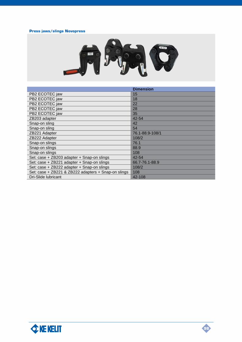
98
Press jaws/slings Novopress
Dimension
PB2 ECOTEC jaw 15
PB2 ECOTEC jaw 18
PB2 ECOTEC jaw 22
PB2 ECOTEC jaw 28
PB2 ECOTEC jaw 35
ZB203 adapter 42-54
Snap-on sling 42
Snap-on sling 54
ZB221 Adapter 76.1-88.9-108/1
ZB222 Adapter 108/2
Snap-on slings 76.1
Snap-on slings 88.9
Snap-on slings 108
Set: case + ZB203 adapter + Snap-on slings 42-54
Set: case + ZB221 adapter + Snap-on slings 66.7-76.1-88.9
Set: case + ZB222 adapter + Snap-on slings 108/2
Set: case + ZB221 & ZB222 adapters + Snap-on slings 108
Dri-Slide lubricant 42-108

99
Press tools Novopress
Dimension
ECO301 + case 12-108
ECO301 + cases + jaws + ZB203 adapter + slings 42-54 12-15-18-22-28-35-42-54
ECO301 + cases + ZB323 and ZB324 adapter + slings 76.1-108 76.1-88.9-108
Press jaws/slings Novopress
Dimension
ECO301 jaw 15
ECO301 jaw 18
ECO301 jaw 22
ECO301 jaw 28
ECO301 jaw 35
ZB303 adapter 42-54
Snap-on sling 42
Snap-on sling 54
ZB323 adapter 76.1-89-108/1
ZB324 adapter 108/2
ECO301 Snap-on sling 76.1
ECO301 Snap-on sling 88.9
ECO301 Snap-on sling 108
Set: Snap-on slings + ZB323 adapter 76.1-88.9
Set: Snap-on sling + ZB324 adapter 108/2
Set: Snap-on sling + ZB323 & ZB324 adapters 108
Dri-Slide lubricant 42-108
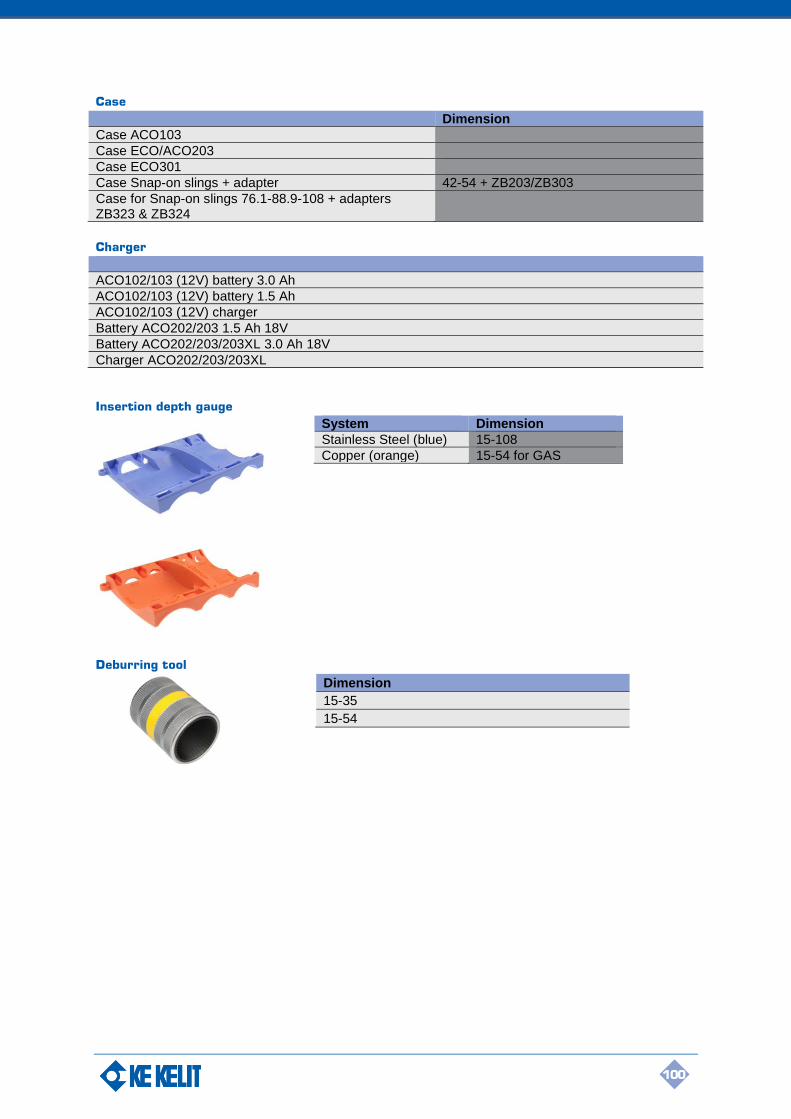
100
Case
Dimension
Case ACO103
Case ECO/ACO203
Case ECO301
Case Snap-on slings + adapter 42-54 + ZB203/ZB303
Case for Snap-on slings 76.1-88.9-108 + adapters ZB323 & ZB324
Charger
ACO102/103 (12V) battery 3.0 Ah
ACO102/103 (12V) battery 1.5 Ah
ACO102/103 (12V) charger
Battery ACO202/203 1.5 Ah 18V
Battery ACO202/203/203XL 3.0 Ah 18V
Charger ACO202/203/203XL
Insertion depth gauge
System Dimension
Stainless Steel (blue) 15-108
Copper (orange) 15-54 for GAS
Deburring tool
Dimension
15-35
15-54

101
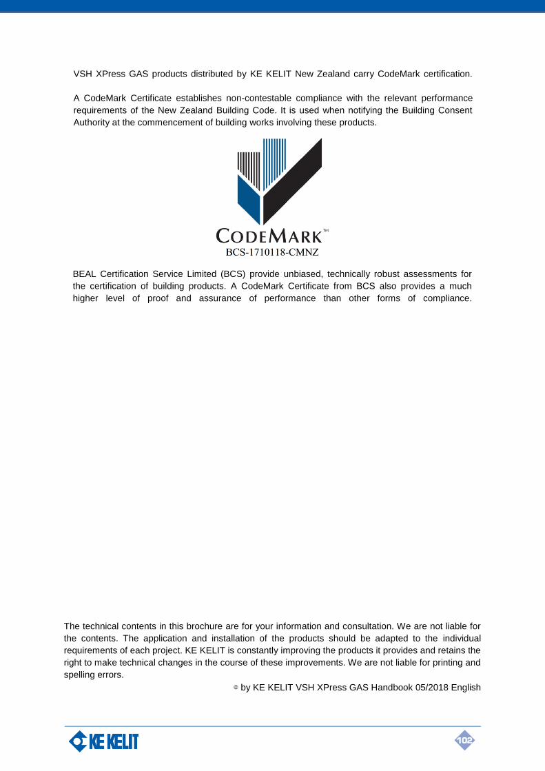
102
The technical contents in this brochure are for your information and consultation. We are not liable for
the contents. The application and installation of the products should be adapted to the individual
requirements of each project. KE KELIT is constantly improving the products it provides and retains the
right to make technical changes in the course of these improvements. We are not liable for printing and
spelling errors.
© by KE KELIT VSH XPress GAS Handbook 05/2018 English
VSH XPress GAS products distributed by KE KELIT New Zealand carry CodeMark certification.
A CodeMark Certificate establishes non-contestable compliance with the relevant performance
requirements of the New Zealand Building Code. It is used when notifying the Building Consent
Authority at the commencement of building works involving these products.
BEAL Certification Service Limited (BCS) provide unbiased, technically robust assessments for
the certification of building products. A CodeMark Certificate from BCS also provides a much
higher level of proof and assurance of performance than other forms of compliance.
KE KELIT NZ
12 Gregory Street, Naenae, Lower Hutt 5011, Wellington, New Zealand
PHONE: +64 (4) 568 4870 E-MAIL: [email protected]
www.kekelit.co.nz