distribution categories: magnetic fusion energy (uc-20
TRANSCRIPT

Distribution Categories:Magnetic Fusion Energy (UC-20
plus UC-20a through -20g
ANL/FPP-79-3
ARGONNE NATIONAL LABORATORY9700 South Cass AvenueArgonne, Illinois 60439
FUSION POWER PROGRAMBIANNUAL PROGRESS REPORT
April —September 1979
Charles C. Baker, Director
Mohamed A. Abdou, Associate Director
-DISCLAIMER •
February 1980
FOREWORD
This bi-annual report describes fusion-related activities in research,development and reactor design, analysis and safety conducted within theFusion Power Program and within other DOE-funded programs at ArgonneNational Laboratory.
The last seven quarterly reports issued were:
ANL/FPP-77-4 July-September 1977
ANL/FPP-77-7
ANL/FPP-78-1
ANL/FPP-78-2
ANL/FPP-78-3
ANL/FPP-78-4
ANL/FPP-79-2
October-December 1977
January-March 1978
April-June 1978
July-September 1978
October-December 1978
January-March 1979
ABSTRACT
This bi-annual report summarises the Argonne National Laboratory workperformed for the Office of Fusion Energy during the April-September 1979quarter in the following research and development areas: materials; energystorage and transfer; tritium containment, recovery and control; advancedreactor design; atomic data; reactor safety; fusion-fission hybrid systems;alternate applications of fusion energy; and other work related to fusionpower.
U
TABLE OF CONTENTS
Page
1.0 FUSION REACTOR MATERIALS , 1
1.1 Alloy Development for Irradiation Performance 1
1.1.1 Effects of Irradiation on Fusion Reactor Materials . 1
1.1.1.1 Radiation Induced Segregation andIrradiation Creep 1
1.1.1.2 Temperature Dependence of Swelling inSingle- and Dual-Ion Irradiated StainlessSteel 7
1.1.2 Hydrogen Permeation and Materials Behavior in Alloys
of Interest to the Fusion Power Program 13
1.1.2.1 Hydrogen Permeation Studies 13
1.1.2.2 Tests of Vanadium Alloy Performance in a
Liquid Lithium Environment 15
1.2 Plasma Materials Interaction 16
1.2.1 Carbon Coatings for Fusion Applications 16
1.2.1.1 Results 181.2.2 Surface Damage of TiBa Coatings Under EnergeticD+ and 4He + Irradiations 23
1.2.3 Suppression of Sputter Induced Erosion Hate fromAlkali Metal Covered Surfaces 28
1.2.4 Sputter-Induced Modification of Near-Surface AlloyComposition 30
1.3 Dosimetry and Damage Analysis 34
1.3.1 Neutron Dosimetry 34
1.3.1.1 Fission Reactor Dosimetry at ORR - LowPower Spectral Measurement 34
1.3.1.2 Fission Reactor DosimPtry at ORR-MFE 1Experiment 36
1.3.1.3 Development of the STAYSL Computer Code . . 38
TABLE OF CONTENTS (cont'd.)
Page
1.3.2 Damage Analysis 43
1.3.3 Cross Section Measurements, Evaluation andTechniques 44
1.3.4 Radiation Damage in Diagnostic Windows forthe TFTR 44
2.0 STARFIRE - A COMMERCIAL TOKAMAK REACTOR DESIGN STUDY 45
2.1 Introduction 45
2.2 Overview of the Reference Design 46
2.2.1 Design Point Selection 46
2.2.2 Reference Design Description 53
2.3 First-Wall/Blanket Considerations for STARFIRE 58
2.3.1 /irst-Wall/Blanket Materials Options 59
2.3.2 Neutronics 61
2.3.3 Tritium and Safety Considerations for the First
Wall and Blanket 63
2.3.4 Mechanical Design of First Wall/Blanket 68
2.4 Maintenance of STARFIRE 70
3.0 FUSION SYSTEMS ENGINEERING 75
3.1 Systems Studies . 75
3.1.1 Technology Development Impact on the Choice of
Fusion Fuel Cycles 75
3.2 Tritium Processing and Control 81
3.2.1 Development of Processing Technology for D-T Fusion
Reactor Breeder Blankets 81
3.3 Engineering Test Facility Studies 85
4.0 FUSION ENERGY APPLICATIONS 92
4.1 Development of Fusion Energy for Alternate Applications . 92

TABLE OF CONTENTS (cont'd.)
Page
5.0 ENVIRONMENT AND SAFETY 94
5.1 Fusion Reactor Safety Studies 94
5.1.1 Studies of Air-Detritiation Operations 94
6.0 MAGNETIC SYSTEMS 96
6.1 Energy Storage and Transfer 96
7.0 APPLIED PLASMA PHYSICS 97
7.1 Atomic Theory „.,
7.1.1 The Bethe Cross Sections for the Ionization ofLi-Like Ions by Electron Impact 97

LIST OF FIGURES
Number
1-1 Comparison of the strain-tine behavior of pure nickel inpre- and post-irradiation conditions . . .
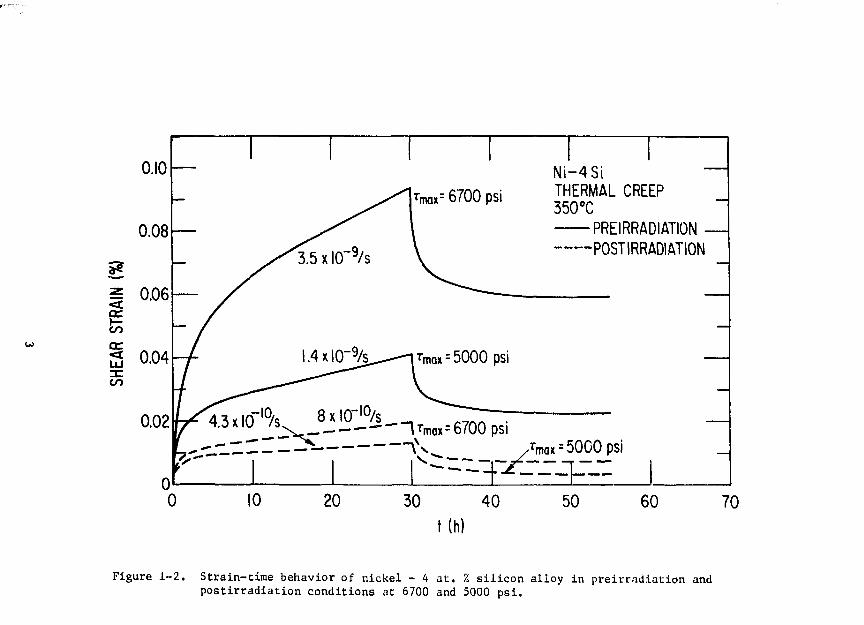
1-2 Strain-time behavior of nickel - 4 at. % silicon alloy inpreirradiation and postirradlation conditions at 6700and 500 psi
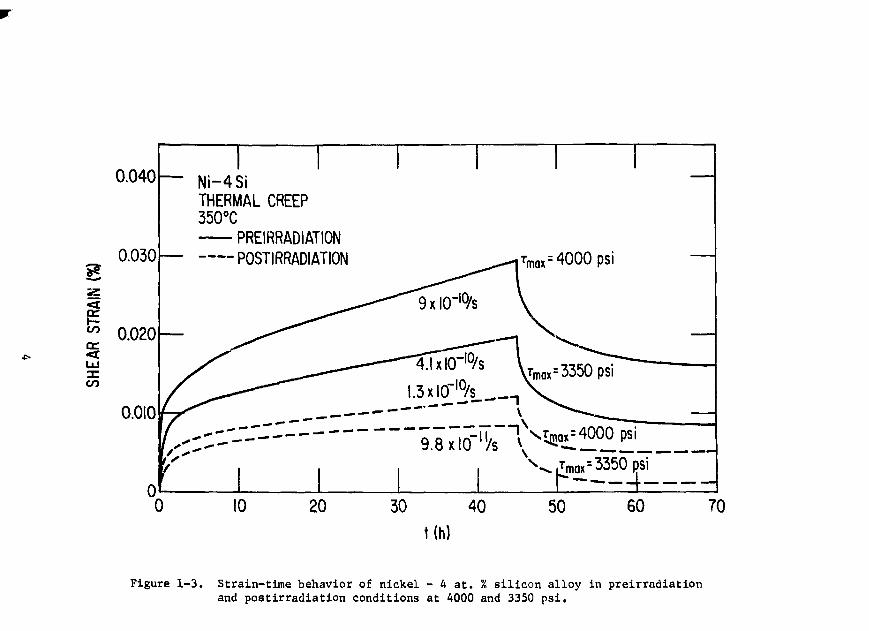
1-3 Strain-time behavior of nickel - 4 at. % silicon alloy inpreirradiation and postirradiation conditions at 4000and 3350 psi
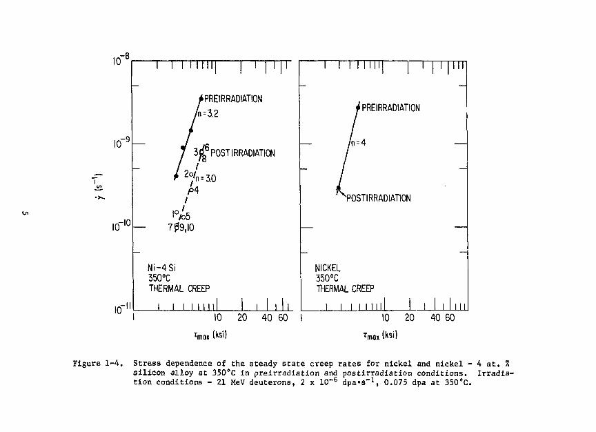
1-4 Stress dependence of the steady state creep rates fornickel and nickel - 4 at. % silicon alloy at 350°C inpreirradiation and post irradiation conditions. Irradia-tion conditions - 21 MeV deuterons, 2 x 10~6 dpa-s"1,0.075 dpa at 350cC
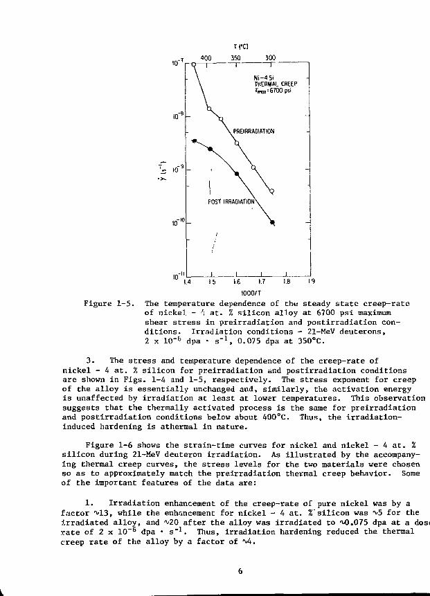
1-5 The temperature dependence of the steady state creep-rateof nickel - 4 at. % silicon alloy at 6700 psi maximumshear stress in preirradiation and postirradiationconditions. Irradiation conditions - 21-MeV deutrons,2 x 10~6 dpa-s-1, 0.075 dpa at 350°C
1-6 Irradiation enhanced creep deformation in pure nickeland nickel - 4 at. % silicon alloy during 21-MeVdeuteron irradiation at 350°C at a dose rate of2 x 10-6dpa.s-1
1-7 Bright-field dark-field pairs showing precipitate-coated cavities in preinjected single-ion and dual-ionirradiated 316 stainless steel (dose = 12 dpa, dose rate =3 x 10~3 dpa-s"1) (a) 603°C dual-ion, (b) dark-field ofsame region as (a), (c) 650°C preinjected single-ion,(d) dark-field of same region as (c) . . . . . . . . . . .
1-8 Absorption contract micrographs of dual-ion irradiated316 stainless steel (dose - 12 dpa, dose rate =3 x 10~3 dpa-s"1, helium injection rate =15:1 appm He:dpa).(a) 540°C, (b) 595°C, (c) 603°C, (d) 633°C, (e) 650°C, and(f) 700°C -. 9
1-9 Temperature dependence of cavity number sensity in dual-ionirradiated 316 stainless steel (dose = 12 dpa, dose rate =3 x 10~3 dpa-s-1). The densities of small and largecavities in the bimodal size distributions are plottedseparately . * 10
vi

LIST OF FIGURES (cont'd.)
Number Pa t
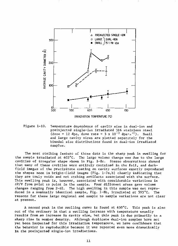
1—10 Temperature dependence of cavity size in dual-ion andpreinjected single-ion irradiated 316 stainless steel(dose = 12 dpa, dose rate 3 x 10"3 dpa s"1). Smalland large cavity sizes are plotted separately for thebimodal size distributions found in dual-ion irradiatedsamples 11
1-11 Temperature dependence of swelling in dual-ion andpreinjected single-ion irradiated 316 stainless steel(dose = 12 dpas dose rate = 3 x 10~
3 dpa s"1) 12
1-12 Temperature dependence of cavity number density inpreinjected single-ion irradiated 316 stainless steel(dose = 12 dpa, dose rate = 3 x 10~3 dpa s"1) 13
1—13 Hydrogen permeation data for as-received and treatedTi-6A1-4V samples 14
1-14 Scanning electron micrographs (SEMs) of fractured edgesof (a) a sooty deposit on a graphite substrate, ar.d (b)a dense adherent coating en a stainless steel substrate . . . 17
1-15 SEM of carbon coated on stainless steel subjected to1000 cycles of 0.5-second pulse, 10-keV electronbombardment at a power level of 37.5 MW/m2. . . . . . . . . . 19
1-16 SEM of carbon coated on stainless steel and ATJ graphiteirradiated at ambient temperatures with D+ ions 20
1-17 SEM of highly oriented pyrolytic graphite irradiated atambient temperature with D+ ions to a dose of 0.5 C/cm2 . . . 22
1-18 Scanning electron micrographs (SEMs) of polishedcoatings irradiated at room temperature for a dose of3.1 x 1018 ions/cm with kHe+ (see A-E), and D+ ions(F-K) for the energies indicated 24
1-19 Histograms of the distribution of blister diametersfor polished TiB2 coatings irradiated at room temperaturewith 15-keV 4He + and D+ to a dose of 3.1 x 10¹⁸ ions/cm2 . . 25
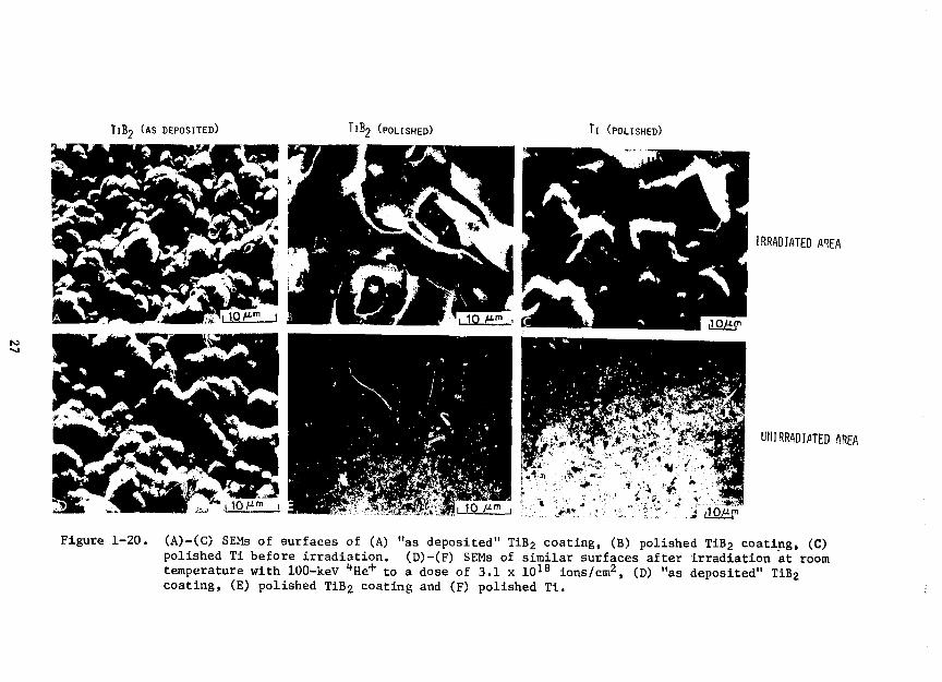
1-20 (A)-(C) SEMs of surfaces of (A) "as deposited" TiB2coating, (B) polished TiB2 coating, (C) polished Tibefore irradiation. (D)-(F) SEMs of similar surfacesafter irradiation at room temperature with 100-keV'•He"'" to a dose of 3.1 x 10¹⁸ ions/cm2, (D) "as depositec"1
TiB2 coating, (E) polished TiB2 coating and (F) polished Ti . 27

LIST OF FIGURES (cont'd.)
Number Page
1-21 Semi-logarithmic plot of erosion yields vs. projectileenergy for plished TiB2 coatings irradiated at ambienttemperatures with D and "*He+ ions for a dose of3.1 x 10 1 8 ions cm"2 28
1-22 Ejection of surface Li atom bonded (a) to the llo substrateand (b) to a multilayer Li film. In the first case thebond is polar-ionic and in the second it is (delocalized)metallic. The metallic bond corresponds to a low bindingenergy and zero net equilibrium charge transfer . . . . . . . 29
1-23 Time dependence of Li and Mo Auger peak-peak signalintensity during sputtering of a multilayer Li film ona Mo substrate. The arrows indicate the first andsecond monolayer . . . . . . . . . . . . . . . . . 31
1-24 Peak-to-peak ratios of the higher-energy Auger transitions,Ni(716 eV) and Cu (920 eV), as function of sputtering timeat different temperatures. Corresponding Ni concentrationsare indicated on the right. A 95 uA/cm2 beam of 5 kV Ar+
ions was used for sputtering 32
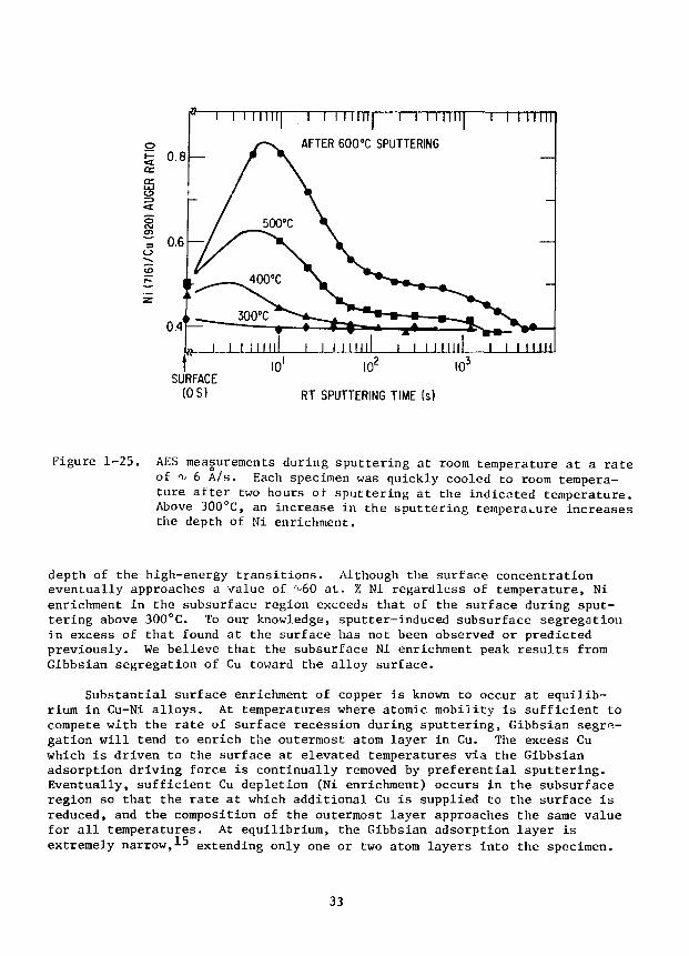
1-25 AES measurements during sputtering at room temperatureat a rate of ^ 6 A/s. Each specimen was quickly cooledto room temperature after two hours of sputtering atthe indicated temperature. Above 300°C, an increasein the sputtering temperature increases the depth ofNi enrichment 33
1-26 STAYSL results for the Oak Ridge Research Reactor.Twenty-one reactions were measured in core locationE7 at a reduced power of 1 MW. Differential fluxtimes neutron energy is plotted. The dashed linesrepresent one standard deviation errors 35
2-1 Cost of energy as a function of neutron wall load. I is theintegral neutron wall load in MW-yr/m and tj is the total down-time in days for replacement of the structural material.Results arc based on fusion pcwer of 3200 IIW, aspect ratio of3.6, plasma elongation of 1.6 and 3t " 0.067 48
2-2 Cost of energy as a function of aspect ratio for a steady-statereactor in two cases for the electrical power, Prf, requiredfor the current-drive system: P . = 0 and P . = 502084Awhere A is the aspect ratio 51
2-3 STARFIRE reactor design 54
2-4 Shield design 58
vlii
LIST OF FIGURES (cont'd.)
Page
2-5 Effect of structural materials on biological hazard potential.The results are based on the following system: first wall:10 mm structural material; blanket: 0.6 m (90% Li + 10%structure); shield: 0.9 m (50% B^C + 50% structure) 64
2-6 Predicted tritium inventory in candidate solid breedingmaterials (20 mesh) as a function of temperature after low-fluence irradiations 66
3-1 Blanket/shield thickness for fusion fuels 77
3-2 Biological hazard potential in air for fusion fuels for
stainless steel structure . . 78
3-3 Relative external doses for alternate fuel system 81
3-4 Lithium processing test loop (LPTL) NB-l%Zr hydrogen metertest 82
3-5 Schematic diagram of the electrical resistance-typeimpurity probe installed in the LPTL 83
3-6 The rate of impurity removal in the LPTL by cold trappingas measured resistoelectrically where p is the electricalresistivity of the lithium solution, po is the resitivitybefore cold trapping, and p,,,, is the resitivity after coldtrapping 84
3-7 Ion microprobe mass analyzer scan of ThO2-Y2O3 oxygen meter
tube exposed to lithium at 480°C for 1500 hours 84
3-8 Fuel cycle scenario for ETF 88
5-1 TS0AK-M1 analysis of duplicate detritiation test data setsobtained with the 0.050 m3 enclosure at ANL 95
3+7-1 Fano plot for the ionization of C by electron impact. T is
the incident energy and a is the cross section. Solid curverepresents the present work, the squares are the experimentaldata from Ref. 3, dotted and dot-dashed curves stand fortheoretical results from Ref. 4 and 5, respectively 99
7-2 Fano plot for ionization of N1* by electron impact. T is theincident energy and a is the cross section. Solid curverepresents the present work, the squares are the experimentaldata from Ref. 3, dotted and dot-dashed curves stand fortheoretical results from Refs. 4 and 5, respectively . . . . 100

LIST OF FIGURES (cont'd.)
7-3 Fano plot for ionization of 05 by electron impact. T is theincident energy and 0 is the cross section. Solid curverepresents the present work, the squares are the experimentaldata from Ref. 3, dotted and dot-dashed curves stand fortheoretical results from Refs. 4 and 5, respectively. . . . . 100
LIST OF TABLES
Number Page
1-1 Nitrogen Analyses of Lithium from the VanadiumAlloy Test Loop 16
1-2 Estimated Erosion Yields Due to Blistering ofPolished TiB2 Coatings Irradiated at RoomTemperature with D+ and He+ Ions for a Dose of3.1 x 10 1 8 ions/cm2 26
1-3 ORR-LP-MFE2A-E7. Comparison of ANL Group Fluxeswith Neutronics Calculations (results normalizedto 30 MW) 35
1-4 Damage Parameters for ORR Calculated with STAYSL
Flux Covariances . . . . . . . . . 36
1-5 Flux Measurements for ORR-MFE 1 37
1-6 Comparison of Estimated Cross Section Errors withIntegral Test Results for Be(d,n), Ed = 14 - 40 MeV . . . . . 39
1-7 Luminescence . . 46
2-1 STARFIRE Major Design Features 55
2-2 STARFIRE Impurity Control . . . . . . . . • 56
2-3 STARFIRE Plasma Current Drive and Heating 57
2-4 Candidate First-Wall/Blanket Materials 60
2-5 Selected First-Wall/Blanket Materials Options . . . . . . . . 60
2-6 Blanket Design Options Used for STARFIRE Neutronic Study . . 62
2-7 Temperature Limits (°C) for Solid Breeders 67
2-8 Scheduled Maintenance 73
2-9 Unscheduled Maintenance (Forced Outage) . 74
3-1 Power Splits for Tokamaks and FRMs 76
3—2 Fuel Processing Requirements for Alternate Fusion Fuel Cycles 79
3-3 Conclusions from the Study of Experimental Breeder/EnergyConversion Module Size Effects 86
3-4 Parametric Analysis of Lithium Processing Requirements forthe ETF Lithium Div-rtor Design 87
LIST OF TABLES (cont'd.)
Number Page
7-1 Bethe Parameters for Discrete Transitions of Li-Like Ions 98
7-2 Bethe Parameters for Li-Like Ions 98
XV1,
1 .' i PL'S WS_ W--\_CTOR__MATE_KIALS
1.1 Al_lo._-.- D e v c : >j'::u : t for i rrad iat i- :i i' r r_t o riTUH]. •
1.1.1 h / i e c t s .•: • i rad i^t io;. . n I" • i - ;. • I Kr.ii.to]' .'-'.a t er i.: 1 s
!.!... 1 R.uiiatiun Indulged Srj.',r'-g.i- i .. ,md I rrad i_at ion ( reep
V. K. l'e(.hi, i- . S i 1 . 1 :•', i. '.'. '-'• I f i , 'v. a m 1 A. 1'. 1. T u r n e r ,Mat e r i i ! •-. .- i n i c e ">i v : •- '. .
.'uring m e a s u r e m e n t s oi i*r niia' I :: . r"i-p U L solutioi. a n n e a l e d and a g e d!vpe 116 -.tain] e s s .-.teel ( M F h \\- . r;iriH' i), it v.as found that d i spl aceT.ent-produi ing r a d i a t i o n onsi.1 \entjv c a n s " ! the samp!i to i reep a g a i n s t t hea p p l i e d s t r e s s ' . !;,is anoir.aious ' -. t-'.. t . .or is a t t r i b u t ' .' to e i t h e r m o d u l u s> b a n g e s c a u s e d by i rrad iat i o n - r n h a n . ! pre.- i p i t.i t ion m tlie ir.et a s t a b l r s o l u -L i. "• n a n n e a l e d 'Ivpe iln stainles'- s i n - ! , i.r d i m r n s i o n a l c h a n g e s causi'd b\p r e c i p i t a l i o n anii/cr s w e l l i n g . In n i d i t i o n , this a l l o y is k n o w n to . x h i h i tc o n s i d e r a b l . - rad iat i o n - i n d u c e d : egreg.it ion (R.'S) "f b o t h m a j o r a n d m i n o ra l l o y i n g e l e m e n t s d u r i n g h e a v \ - i o n i r r a d i a t i o n - .
Tli is r e p o r t d e a l s w i t h e x p e r i:,v-nt: d e s i g n e d in d e t e i m i n c t he e f f e c t ofK I S oil c r e e p d e f o r m a t i o n in a m o d e ! sv.jtem (Ni - -V a l . " S i ) , w i t h a c o m p o s i -t i o n s u c h that no s e c o n d p h a s e exi.;tr 'n r lie a b s e n c e of i r rad i a t i o n . T h ea i l o v w a s c h o s e n b e c a u s e it s i m u l a t e s the s o l u t i o n l a r d r n i n e p r e s e n tloss steel a n d b e c a u s e P.IS and p r e c i p i t a t i o n d o o c c u r in the a l i o " .
in stain-
High nurilv nic!-el and nickel - 4 at. % silicon al <o\ were processed into! O-cm-long, 0. 07 5-cm-rJ iarael: '_>r vires. -"''e nickel wires vere anne.il od at 700°Clor ten pinute:,, and the nickel - k at. '. silicon wires '.-.•err innealed at .^15CCfor two hours in an inert environment. The heat treatmen's were selected togive comparable grain sizes in the two materials. The 'reep .specimen- werefabricated from these wires b. e]ectropolishing a reduced section ( 0.013 cmdiameter and 0.65 cir. long). A typical specimen fabricated in this fashioncontains at least ten giains across the diameter.
Creep measurements were made in the Torsional ilreep Apparatus at 350°C.A 21-MeV deuternn beam was used for irradiation experiments at a dose race of^2 x 10"6 dpa • s"1. l'reirradiation and postirradiation measurements weremade to assess whether irradiation produced significant changes in the struc-ture of the material.
The preirradiation and postirradiation data for the two materials areshown in Figs. 1-1 through 1-5. The main features of the data are:
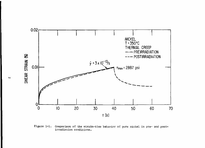
1. Comparison of the data illustrated in Fig. 1-] reveals that in purenickel, for the small doses involved in these tests (^0.^75 dpa), there areno large-scale, irradiation-induced Tiicrostructural changes.
2. Figures 1-2 and 1-3 show the preirradistion and postirradiationdeformation behavior of nickel - 4 at. % silicon alloy. The alloy exhibitsconsiderable irradiation hardening. Since no such hardening is observed inpure nickel, it is likely that the effect is associated with RIS of silicon tointernal immobile sinks, the hardening mechanism being precipitate decoratedloop intersection.
0.02
iCO
cc
CO
c.oi
NICKEL
THERMAL CREEPPREIRRADIATIONPOSTIRRADIATION
50 60 70
t(h)
Figure 1-1. Comparison of the strain-time behavior of pure nickel in pre- and post-irradiation conditions.
N i - 4 S iTHERMAL CREEP350°C
PREIRRADIATION -POSTIRRADIATION
--~~Umax=6700 psi
0
Figure 1-2. Strain-time behavior of nickel - 4 at. % silicon alloy in preirradiation andpostlrradiation conditions at 6700 and 5000 psi.
CO
orLJJ:ECO
0.040
0.030
0.020
0.010
Ni -4S iTHERMAL CREEP350°C
PREIRRADIATIONPOSTIRRADIATION rmax=4000psi
'•Sxicr^/t-
v^LTmox=335Opsi
0 10 20 30 40
t(h)
50 60 70
Figure 1-3. Strain-time behavior of nickel - A at. % silicon alloy in preirradiationand postirradiation conditions at 4000 and 3350 psi.
10
10"
10rIO
10
1 I I I I I 111 I I I II
PREIRRADIATION
3£lD POST IRRADIATION
Ni -4S i350°CTHERMAL CREEP
I I I I M i l l
1 1
/
/
NICKEL350°CTHERMAL
1
1 1 1 I I I 1 1 | III
if PREIRRADIATION
L--A —
POSTIRRADIATION
. CREEP
Mil l i l l , II
'max
10 20 40 60
(ksi)
10 20 40 60
rmox
Figure 1-4. Stress dependence of the steady state creep rates for nickel and nickel - 4 a t . %silicon alloy at 35O°C in preirradiation and postirradiation conditions. Irradia-tion conditions - 21 MeV deuterons, 2 x 10~6 dpa'S"1, 0.075 dpa at 350°C.
10"100
10"
Ni-4SiTHERMAL CREEP
FOST IRRADIATION
_L _L14 15 16 17 18 19
1000/T
Figure 1-5. The temperature dependence of the steady state creep-rateof nickel - '; at. % silicon alloy at 6700 psi maximumshear stress in preirradiation and postirradiation con-ditions. Irradiation conditions - 21-MeV deuterons,2 x 10"6 dpa • s"1, 0.075 dpa at 350°C.
3. The stress and temperature dependence of the creep-rate ofnickel - A at. % silicon for preirradiation and postirradiation conditionsare shown in Figs. 1-4 and 1-5, respectively. The stress exponent for creepof the alloy is essentially unchanged and, similarly, the activation energyis unaffected by irradiation at least at lower temperatures. This observationsuggests that the thermally activated process is the same for preirradiationand postirradiation conditions below about 400°C. Thus, the irradiation-induced hardening is athermal in nature.
Figure 1-6 shows the strain-time curves for nickel and nickel - 4 at. Zsilicon during 21-MeV deuteron irradiation. As illustrated by the accompany-ing thermal creep curves, the stress levels for the two materials were chosenso as to approximately match the preirradiation thermal creep behavior. Someof the important features of the data are:
1. Irradiation enhancement of the creep-rate of pure nickel was by afactor ^13, while the enhancement for nickel - 4 at. %'silicon was ^5 for theirradiated alloy, and ^20 after the alloy was irradiated to .075 dpa at a dosirate of 2 x 10"6 dpa • s"1. Thus, irradiation hardening reduced the thermalcreep rate of the alloy by a factor of 4.

0.02
CO
1 I
IRRADIATION CREEPT=35O°C21 MeV deulerons
Y
—
/
|
1
= 4
• ^
1
xlO"9/s FOR h = 2xlO"6d
/
^7=3xl0"9/S;h-l.6xl0"6
^ — • - " "
< ^ = 2xl0"9/s;h = 2xl0"6
THERMAL_.
1
/NICKELTMK - 2887 psi
dpa/s
dpa/s
^,=3350 psi
Ni-4Si_
"NICKEL
6
t (h)
10
Figure 1-6. Irradiation enhanced creep deformation in pure nickel andnickel - 4 at. % silicon alloy during 21-MeV deuteron irra-diation at 350°C at a dose rate of 2 x 10"6 dpa • s"1.
2. Nickel appears to show a linear flux dependence, although this hasto be explored further.
1.1.1.2 Temperature Dependence of Swelling in Single- and Dual-IonIrradiated Stainless Steel
G. Ayrault, H. A. Hoff, F. V. Nolfi, Jr. and A. P. L. Turner,Materials Science Division
A major question in the irradiation response of candidate fusion reactorstructural materials is the influence of concurrent displacement damage andhelium production. Dual-ion irradiation, using heavy-ions for damage produc-tion and helium ions to simulate gas production by transmutation events pro-vides a means of investigating such effects in the absence of a high energyneutron source.
This report presents preliminary results on the temperature dependenceof swelling in single- and dual-ion irradiated 316 stainless steel. Dose andhelium injection rate dependences of swelling will be determined in futurestages of the program.

Irradiation Conditions - Type 316 stainless steel samples from the MFEheat were 50% cold-worked, then solution annealed at 1050°C for 0.5 h andaged at 800°C for 10 h. One set of samples was simultaneously irradiated with3.0 MeV Ni+ and 0.87 MeV degraded 3He+ in the ANL Dual-Iou Irradiation Facil-ity; the helium injection rate was 15:1 appm He:dpa. A second set of sampleswas preinjected at room temperature with 5 appm 3He, and single-ion irradiatedwith 3.0 MeV Ni+. For both sets the dose level was 12 dpa. The nominal irra-diation temperatures were 550, 600, 625, 650 and 700°C; surface temperaturesof all samples were measured with an infrared pyrometer during irradiation.After irradiation, thei samples were electrochemically sectioned to a depth of4500A (peak damage is at 55OOA), and backthinned for TEM inspection.
Precipitates - Mout of "the irradiated samples contained both cavities andintragranular precipitates, which were not present in unirradiated controlsamples with the same thermal history. In addition, the cavities were coatedwith precipitates in all samples where cavities were found; examples of thisare shown in Fig. 1-7.
Figure 1-7. Bright-field dark-field pairs showing precipitate-coated cavitiesin preinjected single-ion and dual-ion irradiated 316 stainlesssteel (dose = 12 dpa, dose rate = 3 x 10~3 dpa's"1) (a) 603°Cdual-ion, (b) dark-field of same region as (a), (c) 650°C prein-jected single-ion, (d) dark-field of same region as (c).

Swelling in Dual-Ion Irradiated Samples - For dual-ion irradiation in thetemperature range 550 to 650°C, a bimodal cavity-size distribution was found,Fig. l-8a-e; at 700°C, only small cavities were observed, Fig. l-8f. Largecavities were usually associated with the intragranular precipitates, whilethe small cavities were found on both precipitates and dislocations.
Figure 1-8. Absorption contrast micrographs of dual-ion irradiated 316stainless steel (dose = 12 dpa, dose rate = 3 x 10"^ dpa-s"1
helium injection rate = 15:1 appm He:dpa). (a) 540°C,(b) 595°C, (c) 603°C, (d) 633°C, (e) 650°C, and (f) 700°C.

Void number densities, mean void size and void volume were determinedfrom the TEM micrographs. The data are presented in Figs. 1-9, 1-10, and 1-11.Each data point is based on observations in at least three different regionsof the sample; the error bars reflect variations between these regions. Innumerical data analyses, the small and large cavities in the bimodal distri-bution were treated separately, and the cavity number density and size areplotted separately in Figs. 1-9 and 1-10. For void volume, Fig. 1-11, thetwo contributions have been summed, but when large cavities are present, theyaccount for nearly all of the volume.
-i
• SMALL CAVITIESO LARGE CAVITIES
10'550 600 650
IRRADIATION TEMPERATURE CO
700
Figure 1-9. Temperature dependence of cavity number density in dual-ionirradiated 316 stainless steel (dose = 12 dpa, dose rate =*3 x 10"3 dpa-s"1). The densities of small and large cavitiesin the bimodal size distributions are plotted separately.
10
300
85
1 200
A PREINJECTEO SINGLE-IONo LARGE 1DUAL-ION• SMALLJI5: IHe:dpa
100
oi—500 550 600 650
IRRADIATION TEMPERATURE PC)
700
Figure 1-10. Temperature dependence of cavity size in dual-ion andpreinjected single-ion irradiated 316 stainless steel(dose = 12 dpa, dose rate = 3 x 10 ~3 dpa-s"1)- Smalland large cavity sizes are plotted separately for thebimodal size distributions found in dual-ion irradiatedsamples.
The most striking feature of these data is the sharp peak in swelling forthe sample irradiated at 603°C. The large volume change was due to the largecavities of irregular shape shown in Fig. l-8c. Stereo observations showedthat many of these cavities were entirely contained in the foil, and dark-field images of the precipitate coating on cavity surfaces exactly reproducedthe shapes seen in bright-field images (Fig. l-7a,b) clearly indicating thatthey are truly voids and not etching artifacts associated with the surface.This swelling peak is, however, associated with considerable variations inAV/V from point to point in the sample. Four different areas gave volumechanges ranging from 2-6%. The high swelling in this sample was not repro-duced in a nominally identical sample, Fig. l-8b, irradiated at 595°C. Thereasons for these large regional and sample to sample variations are not clearat present.
A second peak in the swelling curve is found at 650°C. This peak is alsoout of the ordinary in that a swelling increase with temperature usuallyresults from an increase in cavity size, but this peak is due primarily to asharp rise in number density. Although duplicate dual-ion samples have notyet been inspected for this irradiation temperature, we have confidence thatthe behavior is reproducible because it was repeated even more dramaticallyin the preinjected single-ion irradiations.
11

5.0
4.0
§ 30
I 20
1.0
A PREINJECTEO SINGLE-IONo DUAL-ION
151 He:dpa
01—500
•SINGLE
550 600 650
IRRADIATION TEMPERATURE CO
700
Figure 1-11. Temperature dependence of swelling in dual-ion and preinjectedsingle-ion irradiated 316 stainless steel (dose = 12 dpa,dose rate = 3 x 10"3 dpa-s"1).
Swelling in Single-Ion Irradiated Samples - In the preinjected andsingle-ion irradiated samples, the cavity size distributions were not bimodal,and rapid swelling near 600°C was not observed. However, the swelling peak at650°C resulting from a peak in void number density was also observed for thesingle-ion irradiations. No cavities were observed in the 625 and 700°Csample and it is interesting to note that unlike all other irradiated samples,no intragranular precipitates were observed either. This suggests a relation-ship betwfen precipitation and cavity formation, but does not explain theabsence of both.
12

10'
I 0 ' 3 —
10"
PREINJECTEDSINGLE-ION
MEASUREDNO CAVITIESOBSERVED
550 600 650
IRRADIATION TEMPERATURE CO
700
Figure 1-12. Temperature dependence of cavity number density in preinjectedsingle-ion irradiated 316 stainless steel (dose = 12 dpa, doserate = 3 x 1CT3 dpa-s"1).
1.1,2 Hydrogen Permeation and Materials Eahavior in Alloys
Recent emphasis in this program has been directed towards (1) studies ofhydrogen permeation in titanium-base alloys and (2) experiments with a small(^0.5-liter capacity) lithium loop fabricated with stainless-steel-clad vana-dium alloy. Pi jgress during the second half of calendar year 1979 is sum-marized below.
1.1.2.1 Hydrogen Permeation Studies
E. H. Van Deventer and V. A. Maroni, Chemical Engineering Division
The hydrogen permeation characteristics of a sample of Ti-6A1-4V that hadbeen anodized on both surfaces (by McDonnell Douglas Astronautics Co.) were
13
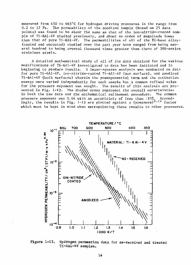
measured from A50 to 665°C for hydrogen driving pressures in the range from0.2 to 17 Pa. The permeability of the anodized sample (based on 25 datapoints) was found to be about the same as that of the ion-nitride-coated sam-ple of Ti-6A1-4V studied previously, and about an order of magnitude loweithan that of pure Ti-6A1-4V. The permeabilities of all of the Ti-base alloy-(coated and uncoated) studied over the past year have ranged from being sev-eral hundred to being several thousand times greater than those of 300-seriesstainless steels.
A detailed mathematical study of all of the data obtained for the variousmodifications of Ti-6A1-4V investigated to date has been initiated and isbeginning to produce results. A least-squares analysis was conducted on datafor pure Ti-6A1-4V, ion-nitride-coated T1-6A1-4V (one surface), and anodizedT1-6A1-4V (both surfaces) wherein the preexponential term and the activationenergy were varied independently for each sample but a common refined valuefor the pressure exponent was sought. The results of this analysis are pre-sented in Fig. 1-13. The shaded areas represent the overall uncertaintiesin both the raw data and the mathematical refinement procedure. The commonpressure exponent was 0.64 with an uncertainty of less than ±10%. Accord-ingly, the results in Fig. 1-13 are plotted against a (pressure)" •fjl* factorwhich must be kept in mind when extrapolating these results to other pressures.
800 700TEMPERATURE/°C
600 500 400 350
1 I 1 =1MATERIAL: T i - 6 A I - 4 V J
-AS - RECEIVED
0.9 I.I 1.2 1.3 1.41000 K/T
1.5 1.6
Figure 1-13. Hydrogen permeation data for as-received and treatedTi-6A1-4V samples.
14
It is clear from the results in Fig. 1-13 that the coating procedurescaused a measurable, but far less than desirable, reduction in the permeabil-ity of H-6A1-4V. The optimized pressure exponent, being significantlygreater than 0.5, suggests that the normally assumed bulk-diffusion-limitedpermeation mechanism is being affected or perhaps totally superseded byanother mechanism which undoubtedly is taking place at the surfaces of thealloy. It is a fact that the product of the hydrogen solubility parameterand the true bulk diffusion parameter for T1-6A1-4V at. temperatures in therange shown in Fig. 1-13 yields a permeability significantly higher than theresults shown in Fig. 1-13. Furthermore, the tendency of calculated permea-tion values based on Lhe (solubility x diffusion) product is to increase withdecreasing temperature, primarily because thi decreasing diffusion parameteris more than offset by the increasing solubility parameter at progressivelylower temperatures. The permeation mechanism observed for these titanium-based materials is certainly not classical and requires more study. Accord-ingly, a sample of high purity titanium has been readied for permeation study,to determine the characteristics of the unalloyed material.
1.1.2.2 Tests of Vanadium Alloy Performance in a Liquid Lithium Environment
D. L. Smith and R. II. Lee, Materials Science Division, andR. M. Yonco and V, A. Maroni, Chemical Engineering Division
Investigations are continuing on (1) the distribution on non-metallicelements in lithium-Path C alloy systems and (2) effects of a lithium envi-ronment on the mechanical properties of selected reactive/refractory metals.Tests are being conducted in a small forced circulation stainless steel-cladvanadium alloy loop. The loop has been operating without interruption forover 10 Ms (>100 days). Initial operation was at 673 K fr>r 2 Ms. Loop tem-perature was then raised to 873 K where it has since been maintained. Teststo date include the taking of four filtered lithium dip samples for determi-nations of the nitrogen concentration in lithium, two exposures of zirconiumfoil and two exposures of vanadium wire. The purpose of the zirconium expo-suras is to reduce the nitrogen concentration in lithium by gettering and toevaluate the hydrogen concentration in the system. The latter determinationwill be accomplished by analyzing the hydrogen concentration in zirconium andobtaining the equivalent hydrogen pressure at equilibrium from literaturedata. Analysis of the nitrogen pickup in the zirconium will provide a measureof the nitrogen in the system. Table 1-1 summarizes results of the nitrogenanalysefj of the lithium. The nitrogen concentration in the lithium has beenreduced from an initial value of ^1340 wppm to ^36 wppm.
Exposure of zirconium foil at 673 K for 0.43 Ms resulted in a gold tar-nish indicative of ZrN on the surface. The zirconium foil exposed at 873 Kfor 0.60 Ms resulted in a heavier gold film on the sample. Electron micro-probe analysis of this film indicated a strong nitrogen count. These resultsare in qualitative agreement with calculated trends for nitrogen transfer.Quantitative analyses of the zirconium samples are in progress.
15

Table 1-1. Nitrogen Analyses of Lithium from the Vanadium Alloy Test Loop
SampleNo.
VL-1
VL-2
VL-4
OperationTime(Ms)
1.10
1.11
5.00
LithiumTemperature
(K)
673
673
871
NitrogenConcentration
(appro)
1342 + 25
1325 + 25
95 + 25
Comments
Represents initialconcentration
Duplicate sample
After exposure ofZr foil for 0.43 Msat 673 K and opera-
tion at 873 K for2.60 Ms
VL-5 6.80 873 36 After exposure of
Zr foil for 0.60 Msat 873 K.
1.2 Plasma Materials Interaction
1.2.1 Carbon Coatings for Fusion Applications
S. K. Das, M. Kaminsky, Physics Division, and L. H. Rovner, J. Chin,and K. Y. Chen, General Atomic Company.
A carbon coating process for fusion reactor first-wall components, adapt-able to application in-situ, would have special advantage by eliminating anyneed for reactor disassembly to repair or refurbish the coating. The deposi-tion process investigated in these studies was the discharge-activated deposi-tion of carbon from methane at about 1 Pa pressure. The coating chamber wasa 76-mm-diameter quartz tube. Either dc or rf (13.56 MHz) discharges wereexcited by 25-mm-diameter electrodes spaced 0.15 m apart. Coatings weredeposited on the interior surface of an independently biased cylindrical sub-strate (50 mm in diameter and 0.15 m long) which surrounded the discharge.
Gross variations in coating morphology are related to the energy densityof the discharge and the negative bias applied to the substrate. Withincreasing values of these parameters, both dc and rf deposits varied fromsooty non-coherent agglomerates (Fig. l-14a), through columnar coatings withrounded surface deposition features, to the smooth, pore-free, nearly feature-less material shown in Fig. l-14b. This last type was obtained for substratecurrent densities of 40 A/m2, bias of 600 V, and temperatures of 700 K.Polarized light and X-ray examinations of coatings cross sections showed themto have an unusual crystallographic orientation with the c-axes primarilyparallel to the plane of deposition.
16
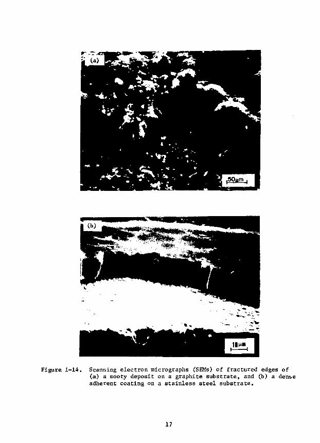
Figure 1-14. Scanning electron micrographs (SEMs) of fractured edges of(a) a sooty deposit on a graphite substrate, and (b) a den&eadherent coating on a stainless steel substrate.
17

The ATJ and highly oriented pyrolytic graphite samples used in thesestudies were obtained from Union Carbide. Two sets of pyrolytic graphitesamples were used, one having the c-axis nearly normal to the. surface and theother having the c-axis parallel to the surface to be bombarded. Both theATJ and the pyrolytic graphite samples were mechanically polished prior toirradiation. The carbon coatines investigated were deposited on copper orstainless steel and vere well-consolidated adherent deposits obtainedat high bias voltages. They had a density of about 1.7 Mg/m', were about10 vim thick, and were used in the "as deposited" condition. Thermal shocktesting was carried out at the Princeton Plasma Physics Laboratory using a10-keV electron beam having a 100-mm2 cross section. The particle irradia-tions were+carried out at Argonne National Laboratory. The beams were massanalyzed D from a dc accelerator in a vacuum of 1.3 x 10"6 Pa. The ionfluxes during the irradiation were in the range 1 x 10¹⁹ - 1 x 10²⁰ ions m"sec "1.
1.2.1.1 Results
Thermal Loading - Carbon coated on a 12-mm-thick copper block did notsustain gross damage for 0.5-sec electron pulse heating powers less than05 MW/m2. At this power, the copper at the interface was melted, and eventhough the coating was mostly spalled off, a thin residual layer of carbondid remain over most of the surface. The performance of this coating wassignificantly better than for an ion-plated carbon coating having the normalcrystallite orientation with c-axes predominantly perpendicular to the depo-sition surface.
A similar sample has been heated cyclically at a lower power level of37.5 MW/m2. Maximum surface temperatures reached were about 1100 K. After1000 cycles of 0.5-sec duration, the coating was cracked but for the most partremained adherent (Fig. 1-15). Even in the few areas where portions of thecoating flaked off, bare copper generally was not exposed. The pattern ofcracks is two-dimensional with a cell size apparently not correlated with theas-deposited features.
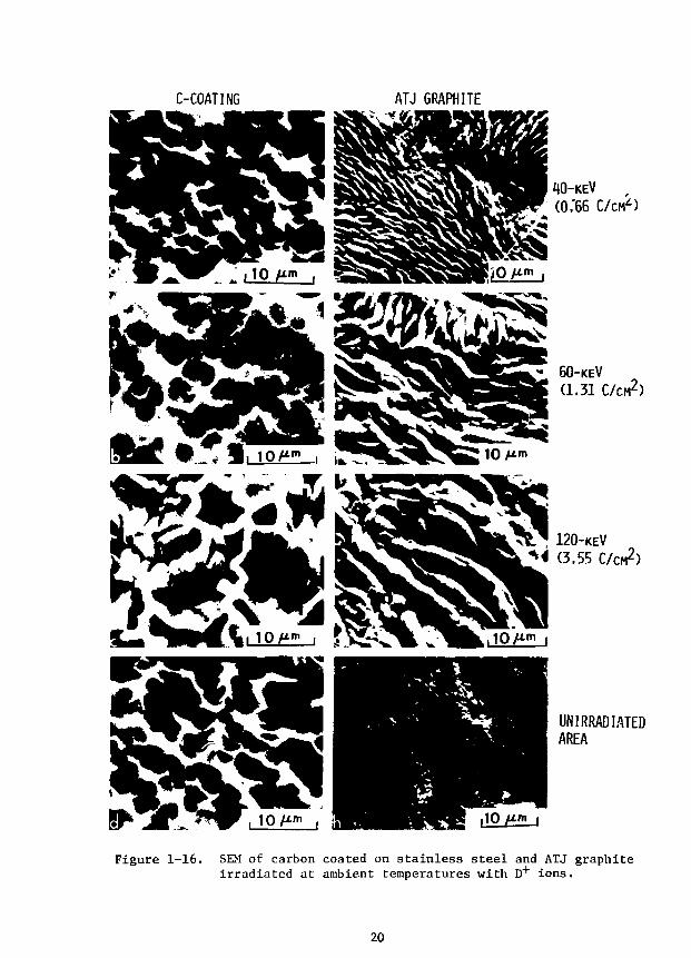
D and He Irradiation Effects - Figures l-16a through l-16c show sur-faces of carbon coatings on stainless steel irradiated at ambient temperatureswith D ions having energies of 40-, 60-, and 120-keV. The total doses,4 x 1022, 8.1 x 10²², and 2.2 x 1 0 " ions m"2, respectively, were chosen tomake a direct comparison with our earlier results on ATJ graphite.* The as-deposited surfaces of the coatings have rounded concave depressions (Fig.l-16d), and no detectable change in the surface topography could be seen forirradiations with 40- and 60-keV D+ (Figs. l-16a and l-16b).
For the 120-keV D irradiation surface, damage in the form of ridges sur-rounding concave depressions could be observed (Fig. l-16c). The amplifiedvertical scale of these features compared with the as-deposited surface sug-gests that the surface has been expanded outward along preferred directions,due to the ion bombardment. The average height of the ridges is about 1.9 urncompared with the average projected range for 120-keV D+ in the coatings of1.3 urn. The lateral extent of the features does not appear to be correlatedwith the unirradiated surface. The occurrence of these ridges for the 120-keVirradiation is flux dependent since no surface damage could be detected at areduced beam intensity, 77 kW/m2 compared with 1200 kW/m2 for the sample in
18

Figure 1-15. SEM of carbon coated on stainless steel subjectedto 1000 cycles of 0.5-second pulse, 10-keV electronbombardment at a power level of 37.5 MW/m2.
19
C-COATING ATJ GRAPHITE
60-KEV(1.31 C/CM 2)
f 120-KEV
1 (3.55 C/CM 2)
UN IRRADIATEDAREA
Figure 1-16. SEM of carbon coated on stainless steel and ATJ graphiteirradiated at ambient temperatures with D+ ions.
20

Fig. l-16c (and 64 and 240 kW/m2 for the 40- and 60-keV irradiations, respec-tively). Possible explanations for this flux dependence may relate to theincreased power deposition and the slightly elevated surface temperature( 500 K), or to the sample microstructure and the mobility of the implantedions.
Ridge formations have also been observed for ATJ graphite, not only for120-keV D+ irradiation under similar conditions (shown for comparison in Fig.l-16g) but also for the 40- and 60-keV D+ irradiations (Fig. l-16e and l-16f).The ratio of the average height to average width of the ridges for the 120-keVD irradiations is only about 1.3 for the carbon coating as compared to aratio of 2.2 - 3.4 for ATJ graphite. Figures l-16e through l-16g show thatthe size of the ridges is clearly dependent on the beam energy. The ridgesobserved on the coated samples are thought to be growth features of the kindreported previously for ATJ graphite1^ and for pyrocarbon^.
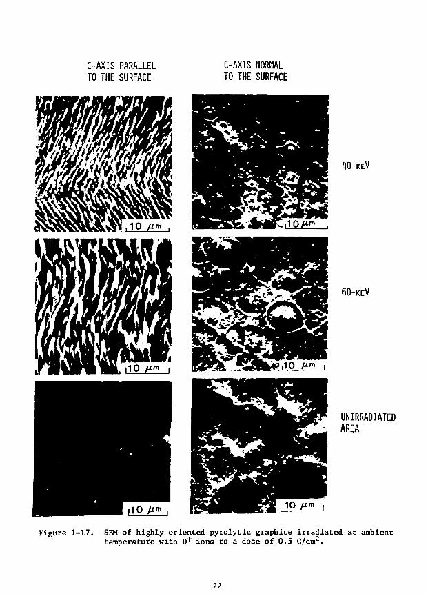
It was suspected that the surface features developed under bombardmentwere characteristic of the sample crystalline structure and orientation. Inorder to study these dependences, highly oriented pyrolytic graphite sampleswere irradiated. Figures l-17a and l-17b show highly oriented pyrolyticgraphite samples, with the c-axis parallel to the surface, which have beenirradiated with 40- and 60-keV D+ ions to a dose of 3.1 x 10²² ions m"2.Surface ridges and grooves have formed that were not present before irradia-tion (Fig. l-17c). The ridges within each grain are predominantly aligned inone direction (Fig. l-17a). Irradiation of surfaces which had their c-axisnormal to the surface (i.e., present basal planes to the ion beam) showed theformation of domes instead of ridges for both 40- and 60-keV D+ irradiations(see Figs. l-17d and l-17e) to the same dose of 3.1 x 10²² ions m~2. Thesedome-shaped features were not present before irradiation, as seen from Fig.l-17f. The nature of the surface features developed is clearly determined bycrystallographic orientation, whereas the size of the features is determinedby the ion energy and its depth of penetration. The coatings shown in Fig.1-16 are less well oriented than these samples, but the surface featuresdeveloped display the ridges expected for their preferred orientation, whichis with the c-axes parallel to the surface.
The nature of the surface damage due to irradiation by D+ on the highlyoriented pyrolytic graphite and carbon coatings show that the damage is stronglyorientation and microstructure dependent; ridge formation occurf on surfaceplanes which have c-axes parallel to the surface, whereas domes are observed onplanes with the c-axes being normal to the irradiates surface (basal planes ex-posed). Similar dome formation has been reported** on basal planes of thin(50-100 nm) pyrolytic graphite samples irradiated at 600-800 K with 70-100 keVHe+ ions for total doses of 5 x 10²¹ to 1 x 10²² ions m~2. These authors con-cluded that the domes were not blisters formed by excess heliuu gas pressure.Furthermore, we have reported earlier^ that the ridges observed on ATJ graphiteare solid, and not hollow (unlike surface blistering) and also that a generalsurface uplifting has been produced in pyrocarbon5 by 0.6 and 3.5 MeV He+. Itcan also be pointed out that Veprek, et al.* observed convolutions to the basalplanes of pyrolytic graphite irradiated with 2 MeV He4" ions at 725 K for a doseof 4.5 x 10²¹ ions m~2. They attributed this surface deformation to the depthdependence of lattice stresses induced by radiation damage. Thus, it appearsthat both the formation of ridges and of domes in the present observations isdue to growth phenomena or lattice expansion and is not associated with thesurface deformation due to excess pressure in gas bubbles.
21
C-AXIS PARALLELTO THE SURFACE
C-AXIS NORMALTO THE SURFACE
40-KEV
60-KEV
UN IRRADIATEDAREA
Figure 1-17. SEM of highly oriented pyrolytic graphite irradiated at ambienttemperature with D+ ions to a dose of 0.5 C/cm2.
22
The surface damage under D irradiations show that the surface damage ofdischarge vapor deposited carbon coatings is less than that of ATJ graphiteor highly oriented pyrolytic graphite, for similar irradiation conditions.The good adherence of these coatings and their relative stability under highenergy ion bombardment reflects favorably on their potential use on variouscomponents in the plasma chamber of a fusion reactor. Their overall meritwill depend on the total erosion rate produced by the complex plasma-wallinteractions to be encountered during actual service, including chemicaleffects of sputtering and stability under neutron irradiation.
1.2.2 Surface Damage of TiB? Coatings Under Energetic D and ''He Irradiations
M. Kaminsky and S. K. Das, Physics Division
Studies of the surface damage and erosion of chemically vapor deposited(.CVD) Til$2 coatings on metallic substrates have been conducted for irradia-tion with 5 + to 120 keV D + and "*He+ ions for different doses at room temper-ature. Furthermore, D+ and He irradiations of commercial grade Ti were con-ducted to study the difference in surface damage and erosion between the TiB2coatings and Ti metal.
The TiB2 coatings were obtained from D. Mattox, Sandia Laboratory. Thethickness of the TiB2 coatings ranged from 15 to 25 urn. The coating surfaceswere characterized by scanning electron microscopy (SEM) and scanning Augermicroscopy (SAM) both prior to and after the irradiations. SEM analysis ofthe "as received" coatings reveal that the TiB2 coatings are quite rough.SAM analysis of the "as received" TiB2 coatings revealed the presence of C,0, Si and Cl impurities which could be subsequently reduced or eliminated bysputter cleaning prior to D+ or He+ irradiation. One set of TiB2 coatingswere mechanically polished with vm alumina powder whereas another set wasleft in the "as deposited" condition. The commercial grade Ti (99.5% pureobtained from Roc-Ric, Belleville, NJ) was given a fine metallographic polishprior to irradiation. The irradiations were carried out with mass analyzedD and He+ ions from a dc accelerator in a vacuum of 1.3 x 10~6 Pa. Theincident ion flux during both the D + and He+ irradiation was ^1 x 101"* ions/(cm2-sec).
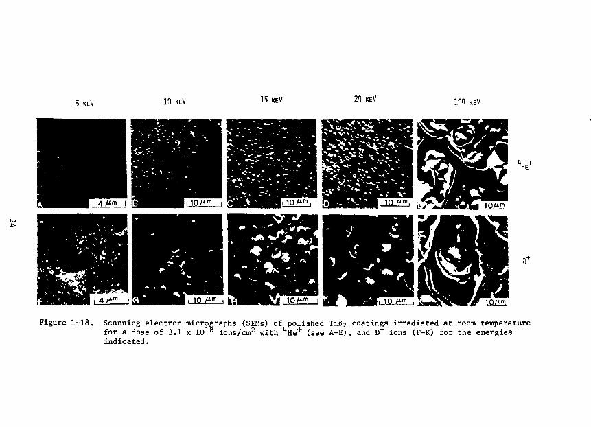
Irradiation of TiB? Coatings - Figure 1-18 shows scanning electron micro-graphs of polished TiB2 surfaces irradiated with 5-, 10-, 15-, 20- and 100-keVHe + (Figs. l-18a through l-18e) and D + ions (Figs. l-18f through l-18k).Here, one notices that the average blister diameter for both D* and "*He+ withenergies in the range 10-20 keV increases with increasing projectile energy(see Figs. i-18b, l-18d and l-18g through l-18i). Furthermore, for a givenenergy in this energy range, the blister diameter for D+ irradiation is largerthan for "*He+ irradiation. This is quantitatively illustrated in Fig. 1-19,which shows the histograms of the distribution of blister diameters for 15-keV4He + and D + irradiations. The most probable blister diameter, Dmp, and theaverage blister diameter, Dav for the 15-keV
1*He+ irradiation are 0.93 pmand 0.86 urn, respectively, whereas for 15-keV D+ irradiation, the value forDmp is 1.51 um and for Dav is 1.48 jim. The observation that the blisterdiameter increases with increasing projectile energy is similar to our earlieron various metals. The latter result, that for a given energy the blistersformed by D+ irradiation are larger than those formed by 1|He+ irradiation issimilar to our earlier observations made on D + and He + irradiated ceramiccoatings.8 This is related in part to the greater depth of penetration ofdeuterons and more importantly, to the lower permeation rate for deuterium thanfor helium in such coatings. This observation may be related to the fact that
23
5 KEV 10 KEV 15 KEV 21 KEV no
D+
Figure 1-18. Scanning electron micrographs (SEMs) of polished TiB2 coatings irradiated at room temperaturefor a dose of 3.1 x 10lS ions/cm2 with "*He+ (see A-E), and D* ions (F-K) for the energiesindicated.

3.0
1.0 2.0 3.0BLISTER DIAMETER <>m)
Figure 1-19. Histograms of the distribution of blister diameters for polishedTiB2 cjoatings irradiated at room temperature with 15-keV 4He +
and D to a dose of 3.1 x 10¹⁸ ions/cm2.
the blister skin thickness is larger and the sputtering yield is lower forthe D irradiation than for He+ irradiation of TiB2 under otherwise iden-tical irradiation conditions.
Quantitative estimates of the erosion yield due to blistering were madefrom measurements of blister skin thickness and the area lost due to blisterexfoliation. These data are summarized in Table 1-2, for room temperatureirradiation of polished TiB2 coatings with D
+ and He+ ions for a dose of3.1 x 1018 ions/cm2. The erosion yields for the 100-keV irradiation are muchlarger than the yields for the low-energy (10-20 keV) irradiations. It may benoted that for irradiations with D + and ''He'1" ions at 100-keV, the blister skinthickness values (0.7 ym and 0.42 urn, respectively) agree well with the pro-jected range calculated (Rp=0.64 ym and 0.40 um, respectively), according toLSS, but for energies < 20 keV, the blister skin thicnessses are larger thanthe calculated projected ranges. For example, for the 10-, 15-, and 20-keVD+ irradiations the measured skin thickness values appear to be about a fac-tor of two larger than the values calculated according to LSS. This can bedue in part to the swelling of the blister skin and to the inaccuracies in theelectronic stopping power used in the range calculation.

Table 1-2. Estimated Erosion Yields Due to Blistering of Polished TiF? CoatingsIrradiated at Room Temperature with D+ and He"1" Ions for a Dose of
3.1 x IP10 ions/cmz
Projectile
10
15
20
100
Erosion Yield (number of TiB2molecules per incident ion).
(O.6-1.4)xlO-2
(0.34-0.75)xl0~2
(0.24-3)xl0-2
0.5 ± 0.2
(0.17-0.35)xlO~2
(0.44-1.5)xl0~2
(0.8-1.4)xl0~2
0.35 ± 0.1
The results described so far are for mechanically polished surfaces, butin a fusion device the coating will most likely be used in the "as deposited"condition. The surfaces of "as deposited" TiB2, polished TiB2, and polishedTi before irradiation are shown in Figs. l-20a, l-20b, and l-20c, respec-tively. Figure l-20d shows a typical result for an "as deposited" Tifr, sur-face irradiated at room temperature with 100-keV "*He+ to a dose of 3.1^x 1018
ions/cm2. For the sake of comparison, polished TiB2 and Ti surfaces irradi-aLed under identical conditions are also shown in Figs. l-20e and l-20f,respectively. Even though the "as deposited" TiB2 surface is very rough, theblisters can be clearly seen in the irradiated area (marked by arrows in Fig.l-20a). The estimated erosion yield for the "as deposited" TiB2 for 100-keVHe+ irradiation at room temperature for a dose of 3.1 x 10¹⁸ xons/cm2 is(4-8) x 10 TiB2 molecules per incident ion, a value which is about twoorders of magnitude smaller than for polished TiB£. This difference in yieldvalues between the "as deposited" (rough) and the polished TiB2 samples issimilar to a trend which had been observed earlier for rough and polished sur-faces of Mo under He ion irradiation^.
The estimated erosion yields due to blister exfoliation for polished TiB2
coatings irradiated with D+ and He+ are plotted in Fig. 1-21 as a function ofprojectile energy. It is interesting to note that for both D+ and "*He+ irra-diations, the erosion yield increases with increasing projectile energy forthe dose studied, and at a given energy the yields are higher for D + irradia-tion than for **He+ irradiation. The former result may in part be due to theincreased power deposition with increased projectile energy. For example,for 40-keV D+ irradiation the power deposition was only 2.5 W cm2as comparedwith 76.2 W cm"2 for the 120-keV D + irradiation. This in turn causes a moder-ate increase in surface temperature (up to about 250°C for the 120-keV irradia-tion) which aids in increased blister exfoliation at higher projectile energies.
26
T1B2 (AS DEPOSITED) TIB2 (POLISHED) T I ( P O L I S H E D )
IRRADIATED AREA
UNIRRADIATED AREA
Figure 1-20. (A)-(C) SEMs of surfaces of (A) "as deposited" TiB2 coating, (B) polished TiB2 coating, (C)polished Ti before irradiation. (D)-(F) SEMs of similar surfaces after irradiation at roomtemperature with 100-keV kHe+ to a dose of 3.1 x 10¹⁸ ions/cm2, (D) "as deposited" TiB2
coating, (E) polished TiBz coating and (F) polished Ti.

g
dent
inci
ecui
es/
oE
No.
of T
Q_1±1
ION
3
10
i
10"'
-210
,63
—i—|—i—i—i—(-
•
A• K"'1'
, I . I . I
i i i i .
"Vv
, i , i .
— i — ' —
5
-
-
—
-
—
-
-
1 I20 40 60 80 100 120
PROJECTILE ENERGY (keV)
Figure 1—21. Semi-logarithmic plot of erosion yields vs. projectile energyfor polished TiB2 coatings irradiated at ambient temperatureswith D + and "*He+ ions for a dose of 3.1 x 10¹⁸ ions cm"2.
For the 40- and 60-keV D + and He+ irradiations of the "as deposited", no surface damage due to blistering could be detected, while the pol-
ished coating surfaces showed significant blister exfoliation. For the120-keV D + and He+ irradiations, the observed blister exfoliation of the "as-deposited" TiB2 coatings is about two orders of magnitude smaller than thatfor the polished TiB2 coatings.
1.2.3 Suppression of Sputter Induced Erosion Rate from Alkali Metal CoveredSurfaces
A. R. Krauss and D. M. Gruen, Chemistry Division
Sputtering is one of the principal mechanisms for the introduction of im-purities into the plasma of magnetic-confinement fusion devices. Under theexpected conditions of low energy light particle bombardment, the sputteredatoms originate almost entirely in the first monolayer of material facing theplasma. It is therefore important to optimize the properties of (at least)the first monolayer so that the sputtered surface introduces the least possi-ble amount of high Z impurity into the plasma. It is desirable to have sur-faces which have a low sputtering-induced erosion rate and which produce sput-tered particles with high secondary ion fraction, low kinetic energy and low
28

atomic number. The surface must also be stable and compatible with the fusionreactor environment. Because of the sheath potential and magnetic fields en-countered in a tokamak, sputtered ions are not expected to contribute to plasmacontamination. However, the lov; secondary ion yield of most materials hasprevented the use of this effect to reduce the impurity influx.
We have succeeded in producing very thin (monolayer) films of lithium ona molybdenum substrate in which the first four criteria have been met, result-ing in a reduction in the sputtering-induced erosion rate in the presence ofan electrostatic field, such as would be produced by the sheath potential ina magnetic-confinement fusion device. Other alkali metal-substrate combina-tions are expected to produce an even greater suppression of the erosion rate.The phenomenon of surface segregation in alloys is expected both experimentallyand theoretically to be a means of obtaining stable, uniform and chemicallypure alkali metal monolayers in a tokamak environment while satisfying thesixth requirement of chemical and thermodynamic compatibility with the fusionreactor.
In order to understand the conditions leading to high secondary ion yields,we have begun preliminary experiments on the secondary ion emission of alkalimetal alloys and adsorbed alkali metal overlayers. The principle of the ex-periment is illustrated in Fig. 1-22. If the alkali metal (eg., Li) is in theform of an adsorbed monolayer (Fig. l-22a) the bond between Li and a high workfunction substrate is largely ionic and there is a high probability that the
(b)
J O O C O J O - (j
f rf f r r r/fx/f,,'' / / ' f ; • - ' / -r ICJOC/ :•- Mo
(a)P
OO CJC GO 0U' j r . '0* t l0O0 O DC COOOOOO * [_j
OGOGCCCOOGOOOr)C OOGOOCOO OCO - MOno r K JOOGGOO OGC
Figure 1-22. Ejection of surface Li atom bonded (a) to the Mo substrate and(b) to a multilayer Li film. In the first case the bond ispolar-ionic and in the second it is (delocalized) metallic. Themetallic bond corresponds to a low binding energy and zero netequilibrium charge transfer.
29 -

alkali metal is sputtered as an ion. If, however, the alkali metal is sput-tered from a multi-layer film (Fig. l-22b) ionic bonding is not possible andother mechanisms are responsible for secondary ion production. If ionic bondbreaking during sputtering is an important, ionization process, the secondaryton yield of the alkali monolayer should be much higher than that of the multi-layer. If a negative bias such as that produced by the sheath potential of atokamak is placed on the sample during sputtering, the positive secondary ionswill be returned to the surface, thereby reducing the sputter-induced erosionrate. Because of the ionic nature of the bond, the adsorbed monolayer has amuch higher binding energy^ and consequently lower sputtering yield and vaporpressure than the bulk alkali metal.
We have used Auger electron spectroscopy to monitor the erosion rate ofmulti-layer and mono-layer Li films on a Mo substrate. The lithium was de-posited by a lithium nluminosilicote ion source. Auger measurements were thenmade while sputtering with and without sample bias. Representative resultsare shown in Fig. .1-23. The data plotted represent the Auger peak-peak signalheight for the Li (40 eV), Mo (28 eV) and Mo (186 eV) transitions. The escapedepth of these electrons is only 2-3 monolayers. The slight step in the Mo(186) signal, at 108 minutes appears to correspond to a 2 monolayer film, whilethe rapid change in all signal intensities starting at 130 minutes correspondsto removal of the last monolayer.
liy comparing the erosion times of the first and second alkali metal layerswith and without sample bias, we hope to be able to specify the ionizationmechanism for sputtered alkali metals. Preliminary results indicate that thefirst monolayer has a longer sputtering lifetime than the secord, regardlessof bias, and that sample bias reduces the erosion rate of the first monolayer.it is expected that in the near future, SIMS and XPS measurements will indi-cate more accurately the secondary ion fraction of these alkali metal mono-layers.
A Li monolayer with a high secondary ion fraction would satisfy the firstfour of the stated requirements (low erosion rate, low secondary ion kineticenergy and atomic number, and high ion fraction). We have previously proposed-^a means of producing such a surface in a self-replenishing manner suitable toa tokamak environment by the use of alloys containing small alkali metal com-ponents. Such materials are air stable and in the case of at least one suchsystenr-3 (Si-Li) have been shown to produce stable Li surface monolayers whenheated to temperatures comparable to those expected for a tokamak first wall.A number of candidate alloys will be examined in future experiments.
1.2.A Sputter-Induced Modification of Near-Surface Alloy Composition
L. E. Rehn and H. Wiedersich, Materials Science Division, andS. Danyluk, University of Illinois
Many properties of the first wall are known to depend upon its near-surface chemical composition, e.g., sputtering rate, corrosion resistance,and susceptibility to radiation blistering. An understanding of sputter-induced compositional changes at alloy surfaces is therefore important forthe design of advanced fusion devices. Under the sponsorship of the Basic
30

1
1
tr i
2T I.Oro !
NO SAMPLE BIAS
Li/Mo
5 keV Ar+
• Li
* Mo(28)
• Mo (186)
60 80 100 ! 120 f 140
SPUTTERING TIME (minutes)
160 180 200
Figure 1-23. Time dependence of Li and Mo Auger peak-peak signal intensityduring sputtering of a multilayer Li film on a Mo substrate.The arrows indicate the first and second monolayer.
Energy Sciences (BES) Program of DOE, we have studied surface and subsurfacecompositional changes induced in a Cu-Ni(40 at. %) alloy during ion sputter-ing at temperatures between 50 and 600°C.
Sputtering of Cu-IJi alloys at room temperature is known to preferen-tially remove Cu. However, only very limited information exists on elevated-temperature sputtering effects and no direct experimental information isavailable on subsurface changes. We have used Auger electron spectroscopy(AES) to investigate near-surface compositional changes in a Cu-40 at. % Nialloy in situ; that is, at temperature during sputtering. Four Auger peakswere monitored: Ni transitions at 102 and 716 eV and Cu transitions at106 and 920 eV. The escape depths of Auger electrons vary with energy. Elec-trons from the low-energy ( 100 eV) transitions have a mean free path of ^4 A,while those from the high-energy transitions (700-1000 eV) have a mean freepath of ^15 A.l^ The low-energy transitions are therefore more sensitive tothe composition of the first few atom layers; the high-energy transitionsaverage the composition over several additional atom layers.
The results of our in-situ measurements can be summarized as follows:At temperatures below 300°C, measurements of the low-energy Auger transitionsshow that the Ni concentration in the top few atom layers rises quickly to
31
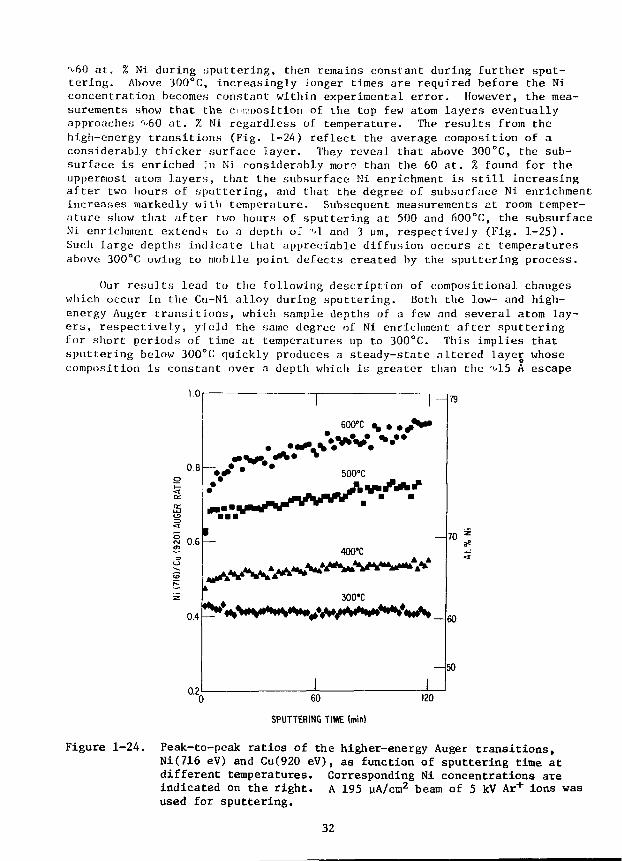
at. % Ni during .sputtering, then remains constant during further sput-tering. Above 300°C, increasingly longer times are required before the Niconcentration becomes constant within experimental error. However, the mea-surements show that the comnosition of the top few atom layers eventuallyapproaches r*'60 at. % Ni regardless of temperature. The results from thehigh-energy transitions (Fig. 1-24) reflect the average composition of aconsiderably thicker surface layer. They reveal that above 300°C, the sub-surface is enriched in Ni considerably more than the 60 at. % found for theuppermost atom layers, that the subsurface Ni enrichment is still increasingafter two hours of sputtering, and that the degree of subsurface Ni enrichmentincreases markedly with temperature. Subsequent measurements at room temper-ature show that after two hours of sputtering at 500 and 600°C, the subsurfaceNi enrichment extends to a deptli oT "'1 and 3 pm, respective]y (Fig. 1-25).Such large depths indicate that appreciable diffusion occurs r.t temperaturesabove 300°C owing to mobile point defects created by the sputtering process.
Our results lead to the following description of compositional changeswhich occur in the Cu-Ni alloy during sputtering. Both the low- and high-energy Auger transitions, which sample depths of a few and several atom lay-ers, respectively, yield the same degree of Ni enrichment after sputteringfor short periods of time at temperatures up to 300°C. This implies thatsputtering below 300°C quickly produces a steady-state altered layer whosecomposition is constant over a depth which is greater than the "vl5 A escape
120
SPUTTERING TIME (min)
Figure 1-24. Peak-to-peak ratios of the higher-energy Auger transitions,Ni(716 eV) and Cu(920 eV), as function of sputtering time atdifferent temperatures. Corresponding Ni concentrations areindicated on the right. A 195 vA/cm2 beam of 5 kV Ar + ions wasused for sputtering.
32
8
i i 11 m i i i i 11 m i i i n n
A F T E R 6 0 0 ° C S P U T T E R I N G
"I I I I III!
i i i 1 1 n i l i i i i m i l i i i 1 1 I I I I I l l l
SURFACE(OS)
IO1 10* IOJ
RT SPUTTERING TIME (s)
Figure 1-25. AES measurements during sputtering at room temperature at a rateof % 6 A/s. Each specimen was quickly cooled to room tempera-ture after two hours of sputtering at the indicated temperature.Above 300°C, an increase in the sputtering temperature increasesthe depth of Ni enrichment.
depth of the high-energy transitions. Although the surface concentrationeventually approaches a value of rf60 at. % Ni regardless of temperature, Nienrichment in the subsurface region exceeds that of the surface during sput-tering above 300°C. To our knowledge, sputter-induced subsurface segregationin excess of that found at the surface has not been observed or predictedpreviously. We believe that the subsurface Ni enrichment peak results fromGibbsian segregation of Cu toward the alloy surface.
Substantial surface enrichment of copper is known to occur at equilib-rium in Cu-Ni alloys. At temperatures where atomic mobility is sufficient tocompete with the rate of surface recession during sputtering, Gibbsian segre-gation will tend to enrich the outermost atom layer in Cu. The excess Cuwhich is driven to the surface at elevated temperatures via the Gibbsianadsorption driving force is continually removed by preferential sputtering.Eventually, sufficient Cu depletion (Ni enrichment) occurs in the subsurfaceregion so that the rate at which additional Cu is supplied to the surface isreduced, and the composition of the outermost layer approaches the same valuefor all temperatures. At equilibrium, the Gibbsian adsorption layer isextremely narrow,l-> extending only one or two atom layers into the specimen.
33

As Cu depletion occurs In the atom layers immediately beneath the surfacelayer, a concentration gradient begins to build toward the interior of thespecimen. This gradient provides a long-range driving force for C'u diffusiontoward the near-surface, Cu-depleted zone. Sputter-induced point defectsenhance the diffusion. Tiie result is a subsurface maximum in the Ni enrich-ment followed by a long Ni-enriched tail which penetrates deep into the spec-imen.
We have shown that sputtering can induce compositional changes beneaththe surface of an alloy which are significantly larger than the changes pro-duced directly at the surface by preferential sputtering. In addition,changes in alloy composition have been observed far beyond the range of thebombarding ions. Those discoveries provide new insight into compositionalchanges that should occur at the plasma-first wall interface during operationof future fusion reactors. They also may lead to useful methods for modifi-cation of near-surface properties of alloys.
1. 3 Oosinietry and Damage Analysis
1.3.1 Neutron Dosinietry
L. R. Greenwood, Chemical Engineering Division
1.3.1.1 Fission Reactor Dosimetry at ORR - Low i'ower Spectral Measurement
Analysis has been completed for the low. power spectral measurement in theOak Ridge Research Reactor. Four 24" long aluminum capsules were irradiatedin core position E7 during January .1.979 at a power level of 1 MW (61.53 MWH).Spectral sets of 10 dosimetry wires were placed at eight locations giving atotal of 28 separate activation measurements at each location. Four wires(Ni, Co-Al, Fe, and Ti) were also placed in each capsule to measure the fluxgradients.
Figure .1-26 shows the measured flux-spectrum at the maximum flux position,about 3" below midplane. Table 1-3 summarizes the measured flux-spectra aswell as neutronics calculations. Whereas our fast flux (>1 MeV) agrees verywell with calculations, our measurements indicate substantially fewer neutronsbelow 1 MeV than predicted by calculation. Three possible explanations forthe difference have been formulated, as follows. First, the calculations didnot include a large graphite cylinder in a nearly core location which wouldindeed moderate the spectrum. Secondly, the measurement was at a reduced powerlevel of 1 MW whereas calculations were at 30 MW. Finally, the neutronics cal-culations (7 group, 3D) may not represent the ORR configuration adequately.Hopefully, these effects can be sorted out by later comparisons to experimentsin the same location at full power (0RR-MFE2) and at other locations (ORR-MFE1)Helium accumulation fluence monitors were also included and are being analyzedat Rockwell International (RI) by H. Farrar IV and D. Kneff. More completeresults of the spectral analysis have been forwarded to E. Bloom (ORNL) andmany DAFS and ADIP Task Group members. Copies are available on request.Table 1-4 lists damage parameters for a year-long irradiation in ORR, similarto the MFE experiments now in progress.
34

o _
cs
o _
OflK RIDGE REfiCTOR E7
Cx_
^ iimm lining iimin ilium iinnn 11111m lining i n inn m n n M I inn tiling
io' loio'9 io"8 io'7 io"6 io"5 IO'1 io'3 io"210"110 101 10ENERGY,MeV
Figure 1-26. STAYSL results for the Oak Ridge Research Reactor. Twenty-onereactions were measured in core location E7 at a reduced power of1 MW. Differential flux times neutron energy is plotted. Thedashed lines represent one standard deviation errors.
Table 1--3. ORR-LP-HFK2A-E7. Comparison of ANL Group Flcixes with NeutronicsCalculations (results normalized to 30 MM)
LowerEnergyMeV
1 x 10⁻¹⁰
5.5 x 10⁻⁷
9.2 x 10~6
1.3 x 10"3
1.2 x 10"2
0.19
>0.92
Total
ANL
16.1
5.4
8.3
2.1
6.4
8.7
13.2
60.3
Row
Calc.
28.5
6.9
11.3
5.7
9.4
11.7
14.7
88.0
Group Flux
22
RatioANL/Calc.
0.56 ± .03
0.78 ± .08
0.73 + .11
0.37 + .22
0.68 ± .41
0.74 ± .19
0.90 ± .07
0.69 ± .10
(1013
ANL
7.3
2.4
3.8
0.93
2.7
3.6
6.1
27.0
n/cm2-s)
Row 9
*Calc.
10.9
2.8
4.7
2.4
3.9
4.9
6.2
35.8
RatioANL/Calc.
0.67 ±
0.86 ±
0.81 ±
0.39 ±
0.69 ±
0.73 ±
0.98 ±
0.75 ±
.03
.09
.12
.23
.41
.18
.07
.11
Seven group, 3D calculat ions provided by T. Gabriel , ORNL (1979).
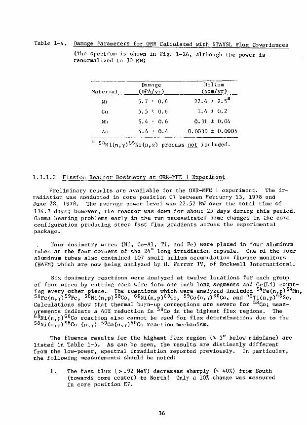
Table 1-4. Damage Parameters for ORR Calculated with STAYSL Flux Covariances
(The spectrum is shown in Fig. 1-26, although the power isrenormalized to 30 MW)
Material
Ni
Cu
Nb
Au
3 ^NMn.y)
Damage(DPA/yr)
5. 7 + 0.6
5.5 ± 0.6
5.4 ± 0.6
4.4 + 0.4
^9Ni(n,a) process
Helium(ppm/yr)
22.6 + 2.5a
1.4 ± 0.2
0.31 ± 0.04
0.0030 ± 0.0005
not included.
1.3.1.2 Fission Reactor Dosimetry at ORR-MFE 1 Experiment
Preliminary results are available for the ORR-MFE 1 experiment. The ir-radiation was conducted in core position C7 between Febi-uary 13, 1978 andJune 28, 1978. The average power level was 22.52 MW over the total time of134.7 days; however, the reactor was down for about 25 days during this period.Gamma heating problems early in the run necessitated some changes in the coreconfiguration producing steep fast flux gradients across the experimentalpackage.
Four dosimetry wires (Ni, Co-Al, Ti, and Fe) were placed in four aluminumtubes at the four corners of the 24" long irradiation capsule. One of the fouraluminum tubes also contained 107 small helium accumulation fluence monitors(HAFM) which are now being analyzed by H. Farrar IV, of Rockwell International.
Six dosimetry reactions were analyzed at twelve locations for each groupof four wires by cutting each wire into one inch long segments and Ge(Li) count-ing every other piece. The reactions which were analyzed included 51*Fe(n,p) 51*Mn,58Fe(n,Y)59Fe, 58Ni(n,p) 58Co, G0Ni(n,p)60Co, 59Co(n,y)60Co, and '*6Ti(n,p)'t6Sc.Calculations show that thermal burn-up corrections are severe for 58Co; meas-urements indicate a 60% reduction in ^8Co in the highest flux regions. The60Ni(n,p)60Co reaction also cannot be used for flux determinations due to the58Ni(n,p)58Co (n,y) 59Co(n,-y)60Co reaction mechanism.
The fluence results for the highest flux region (y 3" below midplane) arelisted in Table 1-5. As can be seen, the results are distinctly differentfrom the low-power, spectral irradiation reported previously. In particular,the following measurements should be noted:
1. The fast flux (>.92 MeV) decreases sharply (y 40%) from South(towards core center) to North! Only a 10% change was measuredin core position E7.
36
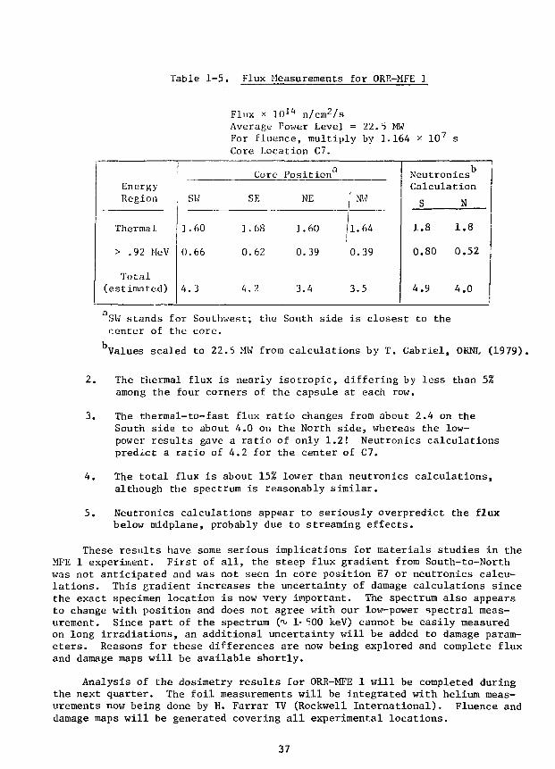
Table 1-5. Flux Measurements for ORR-MFE 1
Flux x 1011* n/cm2/sAverage Power Leve]. = 22.5 MWFor fluence, multiply by 1.164 * 107 sCore Location C7.
EnergyRegion
Thermal
> .92 MeV
Total(estimated)
1
0
4
SW
.60
.66
.3
1
0
4
Core
SF.
.68
.62
.2
Position
NE
1.60
0.39
3.4
NW
1.64
0.39
3.5
NeutronicsCalculation
S N
1.8 1.8
0.80 0.52
4.9 4.0
SW stands for Southwest; the South side is closest to thecenter of the core.
bValues scaled to 22.5 MW from calculations by T. Gabriel, ORNL (1979).
2. The thermal flux is nearly isotropic, differing by less than 5%among the four corners of the capsule at each row.
3. The thermal-to-fast flux ratio changes from about 2.4 on theSouth side to about 4.0 on the North side, whereas the low-power results gave a ratio of only 1.2! Neutronics calculationspredict a ratio of 4.2 for the center of C7.
4. The total flux is about 15% lower than neutronics calculations,although the spectrum is reasonably similar.
5. Neutronics calculations appear to seriously overpredict the fluxbelow midplane, probably due to streaming effects.
These results have some serious implications for materials studies in theMFE 1 experiment. First of all, the steep flux gradient from South-to-Northwas not anticipated and was not seen in core position E7 or neutronics calcu-lations. This gradient increases the uncertainty of damage calculations sincethe exact specimen location is now very important. The spectrum also appearsto change with position and does not agree with our low-power spectral meas-urement. Since part of the spectrum ('v, 1-500 keV) cannot be easily measuredon long irradiations, an additional uncertainty will be added to damage param-eters. Reasons for these differences are now being explored and complete fluxand damage maps will be available shortly.
Analysis of the dosimetry results for ORR-MFE 1 will be completed duringthe next quarter. The foil measurements will be integrated with helium meas-urements now being done by H. Farrar IV (Rockwell International). Fluence anddamage maps will be generated covering all experimental locations.
37
A paper including our work in the Oak Ridge Research Reactor will be pre-sented at the Third ASTM-EURATOM Symposium on Reactor Dosimetry, October 1-5,1979 in Ispra, Italy. The paper is entitled, "Status of Current, RoutineDosimetry at Existing Irradiation Facilities: Flux-Spectrum Mapping at ORR,RTNSII, and U. C. Davis Facilities."
1.3.1.3 Development of the STAYSL Computer Code
The STAYSL code written by F. G. Perey (ORNL) is now operational atArgonne. We have developed procedures for adding covariance errors for rou-tine dosimetric applications. In order to take advantage of our previouslydeveloped cross-section and associated error files, as well as cadmium coverand neutron self-shielding programs, the input to STAYSL has been modified tobe compatible with our Monte Carlo code SANDANL.
There are three types of uncertainty in the input data used for flux-spectral analysis, namely, activation errors, nuclear cross-section errors,and input flux errors. In addition to this, covariance errors must be speci-fied for all related parameters. The STAYSL code then uses a least-squarestechnique to find the minimum value of x2 f°r t n e output flux-spectrum whichbest fits the input data. At present, only activation errors can be treatedrigorously. Errors due to counting uncertainties, detector calibration, andnuclear data are typically less than 2% and covariance effects are negligible.
Nuclear cross-section errors and covariances can in principle be deducedfrom the available experimental data and such files will be published inENDF/B-V. In the meantime, we will continue to use our cross-section errorfiles derived from W. N. McElroy et at, extended to 44 MeV as required forhigh energy dosimetry. Table 1-6 compares our cross-section error estimateswith the results of integral testing in Be(d,n) fields. As can be seen, ourerror estimates tend to be conservatively large.
Input flux errors are unfortunately the most difficult to define. Forexample, the reactor neutronics calculations used as input generally have noerror estimates available. Consequently, we have somewhat arbitrarily as-signed flux errors on the basis of integral data testing and our past ex-perience. Sensitivity studies have been done to assess the importance ofthese error assignments. In regions of good, overlapping foil coverage, in-creasing the input flux errors will only increase the output flux errors upto a point whpre no further effect is seen. This procedure can be used todetermine maxiiuum error limits if no other guidance is available. However,in regions of poor foil coverage, this procedure will fail and one must relyon past experience.
Flux and cross-section self-covariances have been estimated using aGaussian function with a full width of several energy groups. In other words,we are saying that nearby groups must be very strongly correlated; however,widely spaced groups are almost entirely independent. This statement is ana-logous to smoothing the iteration in SAND II and also avoids the problem ofdiscontinuities in the output flux spectrum, especially at sharp resonances inthe cross-section, which are not physical. Covariances between different cross-sections must be determined from experimental data and we must wait for theirpublication in ENDF/B-V.
38
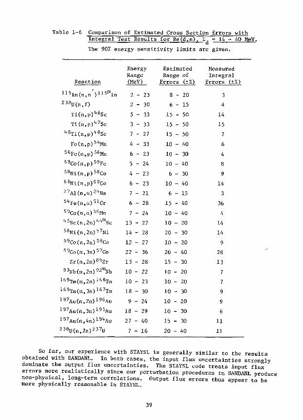
Table 1-6 Comparison of Estimated Cross Section Errors withIntegral Test Results for Be(d,n), E, = 14 - 40 MeV.
' i— dThe 90% energy sensitivity limits are given.
Reaction
115In(n,nV15mIn238U(n,f)
Ti(n,p)lt6Sc
TI(n,p)"Sc4eTi(n,P)
tt8Sc
Fe(n,p)51fMn56Fe(n,p)56Mn59Co(n,p)59Fe58Ni(n,p)58Co60Ni(n,p)60Co27Al(n,a)21tNa51*Fe(n,a)51Cr59Co(n,a)56Mn45Sc(n,2n)^mSc58Ni(n,2n)57Ni59Co(n,2n)58Co59Co(n,3n)57Co
Zr(n,2n)89Zr93Nb(n,2n)92lDNb
169Tm(n,2n)168Tm169Trn(n,3n)167Tm197Au(n,2n)19GAu197Au(n,3n)195Au197Au(n,4n)191tAu238U(n,2n)237U
EnergyRange(MeV)
2
2
5
3
7
4
6
5
4
6
7
6
7
13
14
12
22
13
10
10
18
9
18
27
7
- 23
- 30
- 33
- 33
- 27
- 33
- 23
- 24
- 23
- 23
- 21
- 28
- 24
- 27
- 28
- 27
- 36
- 28
- 22
- 23
- 30
- 24
- 29
- 40
- 16
EstimatedRangeErrors
8 -
6 -
15 -
15 -
15 -
10 -
10 -
10 -
6 -
10 -
6 -
15 -
10 -
10 -
20 -
10 -
20 -
15 -
10 -
10 -
10 -
10 -
10 -
15 -
20 -
of(±%)
20
15
50
50
50
40
30
40
30
40
15
40
40
20
30
20
40
30
20
20
30
20
30
30
40
MeasuredIntegral
Errors (±%)
3
4
14
15
7
6
4
8
9
14
3
36
4
14
14
9
28
13
7
7
9
9
6
11
11
So far, our experience with STAYSL is generally similar to the resultsobtained with SANDANL. In both cases, the input flux uncertainties stronglydominate the output flux uncertainties. The STAYSL code treats input fluxerrors more realistically since our perturbation procedures in SANDANL producenon-physical, long-term correlations. Output flux errors thus appear to bemore physically reasonable in STAYSL.
39
Figure 1-26 shows a flux spectrum determined at the Oak Ridge ResearchReactor (ORR) at a reduced power of 1 MW. The output flux covariance filefrom STAYSL has also been interfaced with our damage parameter codes andTable 1-4 lists calculated damage rates and errors for the ORR spectrum shownir Fig. 1-26.
We intend to use the STAYSL code for most routine fusion dosimetry. Asnew cross-section variance-covariance files are published in ENDF/B-V, theywill be tested and incorporated into the code. A paper has been written con-cerning this work entitled "Uncertainties and Covariances of Spectra Derivedfrom Integral Measurements" for presentation at the Third ASTM-EURATOM Sympo-sium on Reactor Dosimetry, Ispra, Italy, October 1-5, 1979.
1.3.2 Damage Analysis
L. R. Greenwood, Chemical Engineering Division
A meeting of the Damage and Fundamental Studies Subtask Group B was heldat Lawrence Livermore Laboratory on June 7-8, 1979. Our program to calculatedisplacement damage parameters was presented and compared to other existingcodes at HEDL, ORNL, BNL, LLL, and LASL. All codes were found to generallyagree within nuclear cross section uncertainties. Since our files are themost complete (21 elements) and are the only calculations above 20 MeV for 6elements, it was recommended that our data files and programs be adopted forroutine dosimetry applications. We have already been providing this serviceupon request from OFE experimenters.
Our displacement damage files and spectral averaging computer programSPECTER have been sent to Lawrence Livermore Laboratory for inclusion on theNational MFE Computer Network. The data is now being compared to otherexisting damage libraries.
1.3.3 Cross Section Measurements, Evaluation and Techniques
P. T. Guenther, A. B. Smith, D. L. Smith and J. F. Whalen, AppliedPhysics Division and R. Howerton*
Neutron total and scattering cross sections of elemental bismuth weremeasured to energies of approximately 4.5 MeV. The experimental results wereused to deduce an optical-statistical model that is quantitatively descriptiveof the measured values and of higher-energy results reported in the literature.The measured and calculated values, together with the body of information avail-able in the literature, were utilized to derive a comprehensive evaluatednuclear-data file in the ENDF format. This evaluation extended from 10~5
eV to 20 MeV, addressed neutron induced and photon-emission processes andwas oriented toward the needs of fusion-fission-hybrid and electro-nuclearbreeding applications.
Lawrence Livermore Laboratory, Livermore, California
40
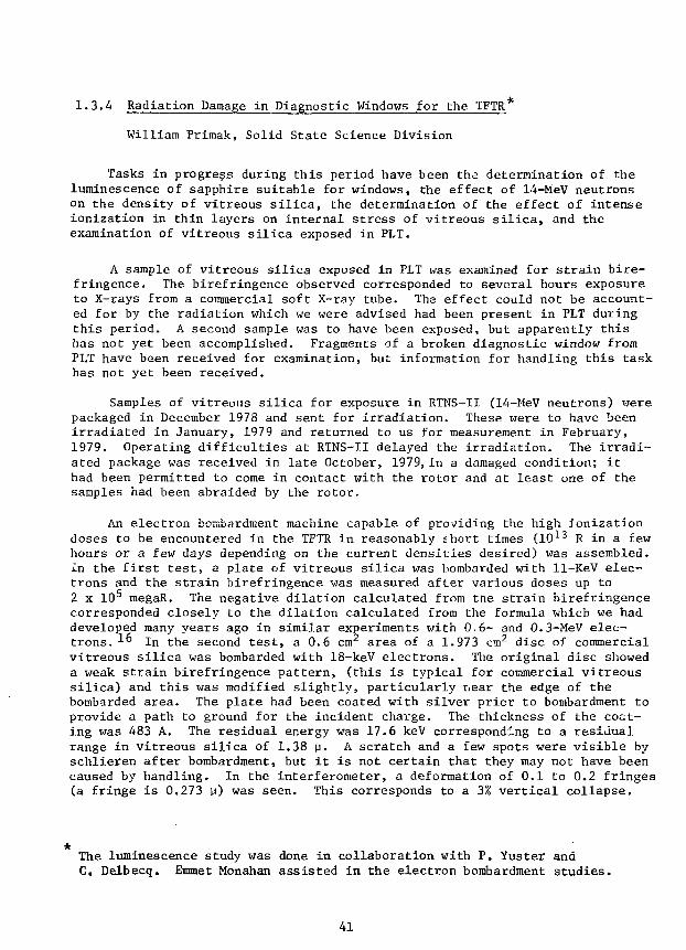
1.3.4 Radiation Damage in Diagnostic Windows for the TFTR*
William Primak, Solid State Science Division
Tasks in progress during this period have been the determination of theluminescence of sapphire suitable for windows, the effect of 14-MeV neutronson the density of vitreous silica, the determination of the effect of intenseionization in thin layers on internal stress of vitreous silica, and theexamination of vitreous silica exposed in PLT.
A sample of vitreous silica exposed in PLT was examined for strain bire-fringence. The birefringence observed corresponded to several hours exposureto X-rays from a commercial soft X-ray tube. The effect could not be account-ed for by the radiation which we were advised had been present in PLT duringthis period. A second sample was to have been exposed, but apparently thishas not yet been accomplished. Fragments of a broken diagnostic window fromPLT have been received for examination, but information for handling this taskhas not yet been received.
Samples of vitreous silica for exposure in RTNS-II (14-MeV neutrons) werepackaged in December 1978 and sent for irradiation. These were to have beenirradiated in January, 1979 and returned to us for measurement in February,1979. Operating difficulties at RTNS-II delayed the irradiation. The irradi-ated package was received in late October, 1979,in a damaged condition; ithad been permitted to come in contact with the rotor and at least one of thesamples had been abraided by the rotor.
An electron bombardment machine capable of providing the high ionizationdoses to be encountered in the TFTR in reasonably short times (10*3 R in a fewhours or a few days depending on the current densities desired) was assembled.In the first test, a plate of vitreous silica was bombarded with 11-KeV elec-trons and the strain birefringence was measured after various doses up to2 x 105 megaR. The negative dilation calculated from the strain birefringencecorresponded closely to the dilation calculated from the formula which we haddeveloped many years ago in similar experiments with 0.6- and 0.3-MeV elec-trons. *-° In the second test, a 0.6 cm area of a 1.973 cm2 disc of commercialvitreous silica was bombarded with 18-keV electrons. The original disc showeda weak strain birefringence pattern, (this is typical for commercial vitreoussilica) and this was modified slightly, particularly near the edge of thebombarded area. The plate had been coated with silver prior to bombardment toprovide a path to ground for the incident charge. The thickness of the coat-ing was 483 A. The residual energy was 17.6 keV corresponding to a residualrange in vitreous silica of 1.38 u. A scratch and a few spots were visible byschlieren after bombardment, but it is not certain that they may not have beencaused by handling. In the interferometer, a deformation of 0.1 to 0.2 fringes(a fringe is 0.273 p) was seen. This corresponds to a 3% vertical collapse.
*The luminescence study was done in collaboration with P. Yuster andC. Delbecq. Emmet Monahan assisted in the electron bombardment studies.
41

Since the radiation-induced negative dilation is about 3%, this corresponds toa plastic flow stress relaxation in which the whole dilation is experiencedperpendicularly to the surface. This phenomenon has been observed in ion bom-bardment of silica,17 but it is the first time it has been reported for elec-tron bombardment. The problem now is to observe the effects when thicker lay-ers are irradiated; in ion bombardment they exhibit a surface crazing.
Determination of the luminescence of sapphire had been scheduled forJune, 1979, but the samples from one of the vendors did not arrive until lateSeptember, 1979. Two samples, one from Crystal Systems (CS) and the otherfrom Union Carbide (UC), were subjected to x-irradiation; and the luminescencespectra were determined with scanning nonochromators. The samples were thentransferred to the electron bombardment machine and the luminescent output wasmeasured in significant parts of the spectra with a photodetector and filters.The arrangements were then calibrated with photometric sources to obtain theabsolute intensity of the luminescence and the luminescent efficiency. Vitre-ous silica was run for comparison. The results are summarized in Table 1—7.The two materials were quite different. The CS material had a strong band at0.41 p while the UC material had a much weaker band below 0.3 p. Both materi-als luminesced at the ruby line, 0.7 v, and both showed side bands in thisregion. The ruby line was much more intense in the UC material. In the CSmaterial the intensity in the ruby line was much less relative to the sidebands. After this work was completed, a sapphire sample from Meller was lentto us and examined visually under X-ray irradiation. Its behavior was quitedifferent from either of the other samples examined. The CS material appearedblue, the UC material appeared red, the Meller material appeared bluish-redand, in addition, displayed a long after-glow. Since the luminescence iscaused by impurity or imperfections in the crystal, it is recommended that theparticular plate to be used be inspected prior to fabrication.
42

Table 1-7. Luminescence
Sample Nos.MaterialSource
Absorbed X-rays (w/cm2)
X-ray luminescence (w/cm2)
Ruby line
Side bands
Total
LE (w /w. . )light loniz
F-band (w/cm2)
LE (w/w)
UV peaks (w/cm2)
0.251 n0.34 v (tail to 0.6 u)0.6 to 0.72 u
Absorbed electrons, low current (w/cm2)
Red light (w/cm2)
LE (w/w)
Blue light (w/cm2)
LE (w/w)
No filter (0.3 \i- ?)(w/cm2)
LE (w/w)
Red filter (w/cm2)
LE (w/w)
4047,4054Sapphire
(UCC)
5.16xlO~4
1.14xlO~8
l.OSxlO"8
2.19xlO"8
4.24xl0~5
8.9xlO~9
3.54xlO~2
5.71xl0~7
1.61xl0~5
4048Sapphire
(CS)
5.16X10-1*
1.02xl0"9
1.02xl0~9
1.97xlO-6
1.14xlO-7
2.21xl0-1+
0.35
4.49x10⁻⁸
1.27xl0-7
1.9xlO"6
bl.12x10-6
4049Silica
(Suprasil)
4.98X10-1*
1.2xlO"n
1.37X10"11
2
6xl0"10
2.9X10"10
2.5xlO~n
1.3X10"11
Corrected for increase caused by silvering
Luminescent Efficiency (LE) is reduced by over an order of magnitude by anexposure of several minutes at 400 megaR/sec (i.e., 105 megaR).
43
REFERENCES
1. V. K. Sethi and F. V. Nolfi, Jr., DAFS Quarterly Progress Report forPeriod Ending December 31, 1978, p. 202.
2. V. K. Sethi and F. V. Nolfi, Jr., DAFS Quarterly Progress Report forPeriod Ending December 31, 1978, p. 103.
3. V. K. Sethi, A. P. L. Turner, and F. V. Nolfi, Jr., DAFS QuarterlyProgress Report for Period Ending September 30, 1978, p. 192.
4. S. K. Das, M. Kaminsky, R. Tishler, and J. Lecchi, J. Nucl. Mat. (1979).
5. L. H. Rovner and K. Y. Chen, J. Nucl. Mat. 63_, 307 (1976).
6. A. S. Rao and D. J. Bacon, Electron Microscopy and Analysis, Int. Phys.Conf. Series No. 36, p. 215 (1977).
7. S. Veprek, A. Portmann, A. P. Webb, and H. Steussi, Rad. Effects 34,p. 183 (1977).
8. T. Rossing, M. Kaminsky, and S. K. Das, J. Nucl. Mat. 63, 325 (1976).
9. K. Sone, M. Suidoh, R. Yamada, and H. Ohtsuc'a, J. Nucl. Mat. 76_, pp. 2-10,(1978).
10. J. W. Gadzuk, Surf. Sci. j> (1967) 133.
11. R. L. Gerlach and T. N. Rhodin, Surf. Sci. JL9_ (1970) 403.
12. A. R. Krauss and D. M. Gruen, Proc. First TOP. Conf. Fusion ReapfnrMaterials. Miami Beach, Florida, January 1979. To be pub. J. Nucl. Mat.
13. M. Lagues, Surf. Sci. 45_ (1974) 432.
14. C. R. Helms and K. Y. Yu, J. Vac. Sci, Technol. 12_, 276 (1975).
15. Yee S. Ngi, T. T. Tsong, and S. B. McClane, Jr., Phys. Rev. Lett. 42_,588 (1979).
16. W. Primak and R. Kampwirth, J. Appl. Physics, 3_9, 5651 (1968); W. PrimakJ. Appl. Physics, 49_, 2572 (1978).
17. W. Primak, Phys. Rev. B14_, 4579 (1976).
44
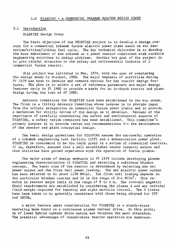
2.0 STARFIRE - A COMMERCIAL TOKAMAK REACTOR DESIGN STUDY
2.1 Introduction
STARFIRE Design Group
The basic objective of the STARFIRE project is to develup a design con-cept for a commercial tokamak fusion electric power plant based on the deu-terium/tritium/lithium fuel cycle. The key technical objective is to developthe best embodiment of the tokamak as a power reactor consistent with credibleengineering solutions to design problems. Another key goal of the project isto give careful attention to the safety and environmental features of acommercial fusion reactor.
This project was initiated in May, 1979, with the goal of completingthe design study ty October, 1980. The major emphasis of activities duringFY 1979 has been to develop and compare options for key reactor design fea-tures. The plan is to select a set of reference parameters and major designfeatures early in FY 1980 to provide a basis for an in-depth reactor and plantdesign during the rest of FY 1980.
Advisory committees for STARFIRE have been established in two key areas.The first is a Utility Advisory Committee whose purpose is to provide inputfrom the utility perspective on commercial fusion power plants and to providea mechanism for utility review of the design as it develops. Because of theimportance of carefully considering the safety and environmental aspects ofSTARFIRE, a safety review committee has been established. This committee'sprimary purpose is to provide review and recommendations for the developmentof the reactor and plant conceptual design.
The basic design guidelines for STARFIRE assume the successful operationof a tokamak engineering test facility (ETF) and a demonstration power plant.STARFIRE is considered to be the tenth plant in a series of commercial reactors.It is, therefore, assumed that a well established vendor industry exists andthat utilities have gained experience with the operation of fusion plants.
The major areas of design emphasis in FY 1979 include developing plasmaengineering characteristics of STARFIRE and selecting a reference blanketconcept. The basic size of the reactor is determined by selecting the netpower output and the first wall power loading. The net electric power outputhas been selected to be about 1150 MW(e). The first wall loading depends onthe particular blanket concept and is in the range of 2-4 MW/m2. This re-sults in reactor major radii in the range of 8 to 6 m. The toroidal magneticfield requirements are established by considering the plasma 6 and any toroidalfield margin required for impurity and alpha particle control. The B limitshave been taken to be generally consistent with those being adopted for ETFand INTOR.
A major feature under consideration for STARFIRE is a steady-stateoperating mode based on a continuous plasma current drive. At this point,an rf lower hybrid current drive option has received the most attention.The potential advantages of steady-state reactor operation are numerous.
45
In particular, such an operating mode is expected to greatly improve theoverall reliability of the reactor. Based on the current theory, it is be-lieved that a steady-state operating mode is possible, but there is atpresent very little experimental verification-
Availability goals have been established as 85% for the reactor and75% for the complete plant including the reactor. These goals provide abasis for design of maintenance equipment. The maintenance scenario incorpo-rates the current utility practice of shutting down annually for one monthand a four month shutdown approximately every 5-10 years.
An important design consideration is the choice of the plasma impurityand alpha particle removal concept. Several schemes have been consideredincluding a limiter/vacuum pumping system, various types of divertors, gaspuffing and plasma boundary flows, and additional margin in the toroidalmagnetic field. Initial investigations indicate that modest pumping ofhelium with a limiter pumping system (^ 15% of the alpha particle flux)coupled with about a 1.5 T margin in the maximum toroidal field may eliminatet.ie need for a divertor, providing that a significant portion of the alphaparticle energy can be radiated to the first wall rather than be depositedon the limiter. With respect to divertor options, particular attentionis being given to developments for INTOR and ETF. In general, a nondivertoroption is greatly preferred from an overall reactor engineering point ofview.
Another key design consideration is the location of the equilibrium field(EF) coils. The basic design approach is to locate almost all the EF coilsoutside of the toroidal field (TF) coils; all such EF coils would be super-conducting. A limited number of segmented coils would be located inside theTF coils, but outside of the blanket and shield.
Safety has played a major role in considering various blanket options.In particular, efforts are being made to minimize the tritium inventory andthe radioactivity induced in the materials in the reactor.
2.2 Overview of the Reference Design
A preliminary reference design has been identified for STARFIRE toserve as a focal point for the design trade studies. The design is modifiedas new requirements or trade study results are defined. The selection of themajor parameters for the preliminary reference design point evolved from ex-tensive system and trade-off studies as summarized below.
2.2.1 Design Point Selection
Previous fusion reactor design and systems studies have demonstrated thepresence of a wide range of design parameters and a diversity of design con-cepts. A primary goal of the STARFIRE study is to select, based on presentknowledge, the most attractive set of design parameters and concepts thatmake tokamaks economically competitive and environmentally acceptable. Inaddition to experience gained from design and systems studies in the United

States and worldwide, extensive tradeoff analyses were carried out to guidethe selection process for STARFIRE. A primary tool for these tradeoff studiesis a comprehensive systems computer program that is capable of predicting theperformance characteristics and economics of the entire tokamak power plant.
The major design parameters that characterize a tokamak reactor are thereactor power, the neutron wall load, aspect ratio, plasma elongation, majorradius, plasma beta, magnetic field, scrape-off region thickness, and blanket/shield thickness. A brief review of the considerations that were factoredinto selection of these major parameters is presented below.
Reactor Power
It has been shown that tokamak reactors exhibit an economy of scale; i.e.larger power reactors have lower cost of energy. However, three considera-tions important to the utilities limit the desirable power rating of a plant.The first is the difficulty of raising the capital for larger power plants.The second relates to the cost of reserve electric power capacity that theutility must provide to compensate for scheduled and unscheduled outages.The cost of reserve capacity increases with the size of the individual powerplant. The third is the maximum capacity of a single turbine generator. Basedon recommendations by the Utility Advisory Committee for STARFIRE, the mostdesirable power rating at present is in the range of 3000-4000 MW for thermalpower and *v 1250 MW for electrical power. Therefore, the fusion power forSTARFIRE was selected as 3200 MW. This corresponds to a nominal thermalpower of % 3800 MW, based on a 21 MeV per fusion reaction, and a net electricpower of % 1150 MW. The recoverable thermal power will be modified by theaddition of rf power for current drive and the loss of low temperature heatsuch as that in the limiter system.
Neutron Wall Load and Structure Life
A key parameter that has a substantial impact on the physical size ofthe reactor is the neutron wall load (Pj,jy) • For the same fusion power, ahigher P results in a smaller surface area, higher power density, smallerreactor volume and potentially lower cost. This underlines the motivationfor developing designs with higher wall loads.
There are limitations, however, on the ability to produce and use highwall loads. The upper limits on the use of high wall loads are dictatedprimarily by the first-wall cooling capability and the structure lifetime.Constraints such as the maximum operating temperature and thermal stressesplace an upper-bound on the allowable wall load. For typical structuralmaterials such as ferritic steels in pulsed reactor systems, the neutron wallload should be limited to >\i 2.5 MW/m2 for helium coolant. Higher wall loadsare possible with water and lithium coolants. In general, the maximum allow-able wall load is higher for steady-state reactors.
For a given fluence lifetime, the neutron wall load should be limited sothat the frequency of structure replacement is not excessive. In order tolimit the fractional increase in the cost of energy due to the plant downtime
47

for replacement of the structural material to 6, the structure lifetimemust be sufficiently long to satisfy the following inequality:1
3656
where t is the structure lifetime in years and t, is the total cumulativedowntime in days for replacement of the structural material. For example,in order to limit the increase in the cost of energy to 10% (i.e. 6 » 0.1)when the downtime is 125 days the structure lifetime must be greater than3.4 yr.
For a given structural material and a fluence lifetime, the loss ofenergy production resulting from choosing high P n w and short t , must beweighed against the economic gain realized by designing a small size reactor.Figure 2-1 shows the cost of energy as a function of the neutron wall loadat two values of the integral neutron wall load, I w, of 5 and 20 MW-yr/m
2
and at two different values for the total cumulative downtime, t^, forreplacement of the structural material. For I w = 5 MW-yr/m
2 and downtime
NEUTRON WALL LOAD, MW/m'
Figure 2-1. Cost of energy as a function of neutron wall load. I,, is theintegral neutron wall load in MW-yr/m2 and tj is the total down-time in days for replacement of the structural material. Resultsare based on fusion power of 3200 MW, aspect ratio of 3.6, plasmaelongation of 1.6 and 6t = 0.067.
48

of 125 days the neutron wall load should be kept in the range 2-2.5 MW/m2.For Iy •v 20 MW-yr/m2 the cost of energy decreases significantly as the neu-tron wall load is increased from 1 to 2 MW/m2. A smaller, but significantsaving in the cost of energy (COE) is realizable by increasing P ^ from2 to 3 MW/m2. A slight change in COE is noticeable in the range Pflw 3-4MW/m2. The reasons for the modest increase in COE as P is increasedbeyond •v 4 MW/m2 will become evident from discussions later in this section.
It is clear that the achievable lifetime of the structural material hasa significant impact on the cost of energy. By eliminating short plasmapulses and designing STARFIRE for steady-state operation, it is anticipatedthat a fluence lifetime of 20 MW-yr/m2 or greater is obtainable with selectedcandidate structural materials. There are several important advantages forsuch a long life: (a) the cost of energy is substantially reduced becauseof less frequent replacement and higher availability factor; (b) when thefrequency of replacement is substantially reduced, the cost of energy becomesless sensitive to moderate variations in the downtime. This is quite importantas it permits flexibility in the reactor design not available otherwise fordesigns driven primarily by the need for achieving very short downtime; (c)a less frequent replacement of the structural material results in a lowerinventory of radioactive materials for which storage has to be provided. (Itshould be noted that even for the candidate structural materials with nolong-term activation, adequate radioactive storage is necessary for two tofive decades); and (d) the demand on material resources is less with longerlife.
For a given fusion power, plasma elongation and aspect ratio, a higherwall load implies a higher plasma density, P . This varies as Pp ^ B^
4.Since the plasma (3 is limited by stability considerations, a higher P isobtainable only by providing a higher magnetic field. For Pnw > 2 MW/m
2 thereis % 1 T increase in the required Bm for every 1 MW/m
2 increase in Pnw. Theeconomically attractive range for Pnw of 3-4 MW/m
2 requires a maximum toroidalfield in the range 10-12 T which is considered acceptable for STARFIRE design.
In light of the above considerations, a neutron wall load of 3.5 MW/m2
has been selected for STARFIRE. This moderately high wall load appears to bea reasonable choice that makes it possible to design a relatively small sizereactor without excessive requirements on first-wall cooling capability, maxi-mum toroidal magnetic field, and frequency of structural material replacement.
Plasma Beta
2Previous systems studies have indicated significant economic benefits
for operating at high average plasma toroidal beta, 3t. However, the maxi-mum realizable St is limited by plasma stability considerations. Based onrecent theoretical analysis, the relationship Bt = 0.24/A, where A is theaspect ratio, has been assumed for the STARFIRE study.
Plasma Elongation
The elongation (K = b/a) of a D-shaped plasma has a significant impacton the plasma performance, the reactor design characteristics, and economics.In particular, at higher K the achievable 3t is higher but the required EF
49

coil system becomes more complex and costly. Based on previous work, avalue of K = 1.6 was selected for STARFIRE. This is believed to be nearlythe upper limit on elongation if the important design goal of locating mostof the EF coils external to the TF coils is to be achievable.
Power Requirements for Current Drive
Since STARFIRE will operate in a steady-state mode, a particularly im-portant aspect of the design is the mechanism for plasma current drive.Lower-hybrid rf is the selected option for current drive. An importantimpact of the current drive system on the reactor performance and economicsis the electrical power requirements for this system. The dependence of themagnitude of this power for the rf system on key plasma and reactor designparameters is discussed below.
3 4The theory of lower-hybrid wave-drive currents ' indicates the ratio
of rf power density to current density is proportional to the electron density.Thus, rf power is reduced by operating at higher plasma temperatures (lowerdensities for a fixed beta). However, as the plasma temperature increasesabove ^ 10 keV, the fusion power density starts to decrease and the ratioof rf power to fusion power is a minimum in the range 15-18 keV. In survey-ing reactor operation at various temperatures, the desire to minimize rfpower calls for considering temperatures above 10 keV, but larger toroidalfields needed to keep the total fusion power at 3200 MW must also be ack-nowledged at these higher temperatures.
In determining the dependence of reactor design on aspect ratio (A), fora fixed total power and wall load and for 3t = A"
1, the total current increasesgoing to lower aspect ratio, while the major radius and plasma density de-crease. Based on the analytic formula *
P = C R "n I ,rf e '
the rf power required to drive reactors for a series of equilibria in therange 3 < A < 4 was computed. The coefficient C is a function of the plasmaprofiles, spectral width, and degree of current penetration; for typicalreactor parameters, and for both centrally peaked and surface current densityprofiles, the rf power increases by 30-50% if the aspect ratio is reducedfrom 4.0 to 3.0. Hence, large values of A are preferred from the rf powerpoint of view.
Major Radius and Aspect Ratio
With the fusion power and neutron wall load selected, the surface areaof the plasma is defined. For a given K, the aspect ratio (A) or the majorradius (R) should be selected in order to fully define the plasma geometry.At Pnw = 3.5 MW/m
2, the major radius increases from 6 m to «v» 7.3 m if A isincreased from 2.6 to 4.0.
The size of the reactor building, length of piping, etc. are stronglyaffected by the size of the reactor, in particular, by the value of R + a,
50
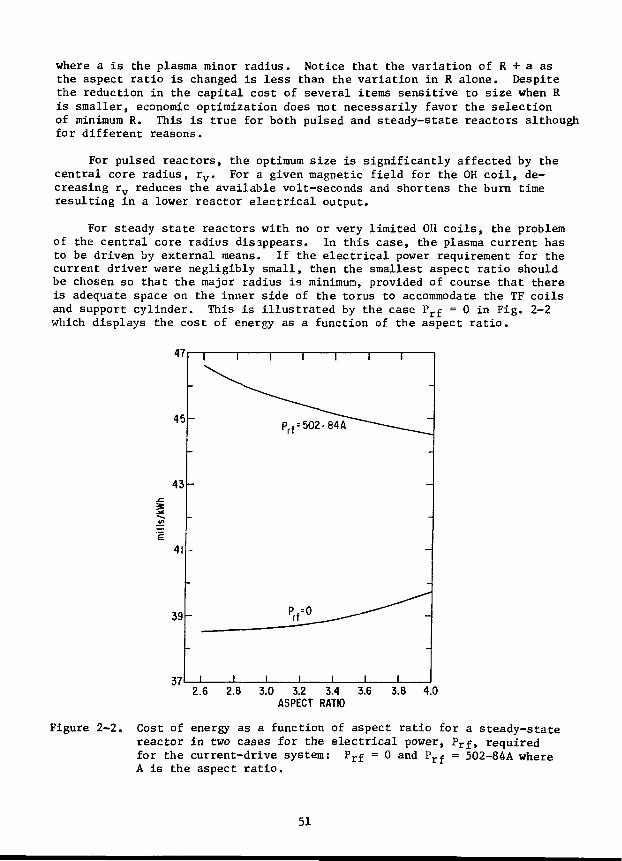
where a is the plasma minor radius. Notice that the variation of R + a asthe aspect ratio is changed is less than the variation in R alone. Despitethe reduction in the capital cost of several items sensitive to size when Ris smaller, economic optimization does not necessarily favor the selectionof minimum R. This is true for both pulsed and steady-state reactors althoughfor different reasons.
For pulsed reactors, the optimum size is significantly affected by thecentral core radius, rv. For a given magnetic field for the OH coil, de-creasing rv reduces the available volt-seconds and shortens the burn timeresulting in a lower reactor electrical output.
For steady state reactors with no or very limited OH coils, the problemof the central core radius disappears. In this case, the plasma current hasto be driven by external means. If the electrical power requirement for thecurrent driver were negligibly small, then the smallest aspect ratio shouldbe chosen so that the major radius is minimum, provided of course that thereis adequate space on the inner side of the torus to accommodate the TF coilsand support cylinder. This is illustrated by the case Prf = 0 in Fig. 2-2which displays the cost of energy as a function of the aspect ratio.
2.6 3.0 3.2 3.4ASPECT RATIO
Figure 2-2. Cost of energy as a function of aspect ratio for a steady-statereactor in two cases for the electrical power, Prf, requiredfor the current-drive system: Prf = 0 and Prf = 502-84A whereA is the aspect ratio.
51

As discussed earlier in this section, the electrical power requirement,Prf, for the rf current drive system appears to be relatively large and in-creases with lower aspect ratio. Figure 2-2 shows the dependence of the costof energy on aspect ratio for the case where Prf = 502-84A, with Prf in MWelectric. In this case the cost of energy decreases as A increases up toA -v 4. It is anticipated, however, that as a result of further work the rfpower requirements will be reduced significantly. This would reduce theoptimum aspect ratio somewhat below A = 4. Therefore, A = 3.6 was adoptedfor STARFIRE. This results in a major radius R = 7 m. The maximum magneticfield required is nearly minimum at A = 3.6.
Inner Blanket/Shield Thickness
The thickness, A* , of the blanket and shield on the inner side of thetorus, or more precisely the distance in midplane from the plasma side ofthe first wall to the location of the maximum toroidal magnetic field, has asubstantial impact on the reactor size, the required strength of the magneticfield and reactor economics. A comprehensive investigation of the optimumvalue for A^ has been carried out previously.5 The details of this previouswork will not be repeated here, but the results are briefly stated.
For a given Pf, Pnw, 0t, and major radius, the advantages of a smallerA* are 1) lower maximum magnetic field and 2) larger central.core (OH)radius, rv. In pulsed tokamaks, the impact of the value of A on rv islarge and becomes critical for low Pf high Pnw designs. In a steady statetokamak with no OH solenoid, the primary incentive for reducing A| is toreduce the maximum magnetic field required.
On the other-hand, there are several penalties for making A g too small.The increase in the radiation field when A* is decreased results in a) in-crease in the resistivity of the stabilizer material and a need for increasingthe amount of the stabilizer to satisfy the cryogenic stability requirements,b) a decrease in the critical current density of the superconductor necessi-tating the use of more superconductor, and c) an increase in the heat genera-tion rate in the TF coil since the increase in the power requirements for theTF coil cryogenic system can be so large that the reactor net electricalpower output is seriously reduced.
For the preliminary reference design of STARFIRE a value of A g = 1.2 mwas selected based on careful considerations of the above trade-offs. Thisvalue includes i, 25% void to account for the vacuum gap in the TF coil andthe use of helium coolant in a portion of the inner blanket, if necessary.The shield consists of a combination of tungsten, boron carbide, lead and astructural material.
Outer Leg of the TF Coils
For a given major radius (R), plasma inner radius (a) and inner blanket/shield thickness (AjL) the position of the inner leg of the TF coil is de-fined. In order to rully define the D-shape of the TF coil, the size of thevertical or horizontal bore must be selected. We will discuss this choicein terms of R2, the major radius of the midpoint of the outer leg of the TFcoil. R2 is the sum of the major radius, first wall minor radius, outer
52
blanket/shield thickness (ABS), clearance (Ac) in the midplane from the outeredge of the shield to the TF coil and half of the TF coil thickness. Thechoice of R2 has a significant impact on many of the reactor characteristicsand cost as discussed below.
With.the reactor parameters previously defined in this section (R, a,Av, Bm, Agg) the only remaining parameters that affect R2 are Agg
and A .The necessary value of Agg varies with blanket and shield material and coolantchoices. As a goal, the materials in the shield should be chosen to haveinherently low long-lived radioactivity even if they are less efficient inradiation attenuation. For typical material choices, the required Agg is^ 1.3 m and ^ 1.8 m for blanket with water (or lithium) and helium coolants,respectively. The clearance from the outer edge of the shield to the TF coilsis required for several engineering reasons; the most dominant of which is toaccommodate the coolant manifolds. The required R2 is <v 12 m for water orlithium coolants compared to 1. 13 m necessary for halium coolants.
The economics analysis shows a substantial penalty for increasing R2«The cost of energy increases by <\< 3% for each additional meter increase inthe value of R2 beyond 12 m. The cause of this penalty is that the value ofR2 directly influences the size and weight of the TF coils and their supportstructure, the size of the reactor building, the length of the piping for theheat transport system, and the size of the externally located EF coils. Forexample, by increasing R2 from 12 to 14 m, the ampere-turns and stored energyin the EF coils nearly double.
It sould be noted that in order to keep the field ripple at the plasmato an acceptable level, the value of R2 should be greater than a certain mini-mum. The minimum value for R2 is larger for a smaller number of TF coils. Arelatively small number, 12, of TF coils has been chosen for STARFIRE to en-hance reactor maintainability. This makes extending the TF coils as a meansof satisfying the field ripple criteria economically unattractive. Therefore,the alternative of an imposed field-ripple correction system (e.g. saddlecoils or iron blocks will be provided if necessary.
2.2.2 Reference Design Description
The reactor cross section is shown in Fig. 2-3 and the design and operatingparameters are given in Tables 2-1 through 2-3.
The reactor magnet system design includes twelve 11 Tesla TF coils. TheEF coil system includes 4 segmented copper coils inside the TF coils for plasmastability control, but most of the EF coils are superconducting and locatedoutside the TF coils for plasma equilibrium. The plasma startup, heating andcurrent drive is accomplished by a lower hybrid rf system. This system reducesthe need for ohmic heating coils and minimizes the need for dielectric breaksin toroidal conductors. The shield incorporates dielectric breaks to preventtoroidal current flow and permit the EF coils that are located inside the TFcoil to have adequate response time for plasma stability control.
53

SECTION VIEW BETWEEN TF COILS
HELIUMOUTLET DUCT
BLANKET21 SECTORS]]
TF COIL
MECHANICALDISCONNECTS
SUPERCONDUCTINGEF COILS J
54

VACUUM PUMP
VACUUM DUCT
SEGMENTED COPPEREF COILS
n, •TF COIL
SHIELD ACCESS DOOR
ACCESS DOOR —
SUPFPCOMDUCTING EF COILS
HELIUM INLETDUCT
OUTLET DUCT
INLET DUCTS
A - A
TF COILSTARFIRE REACTOR DESIGN
I FIGURE 2-3
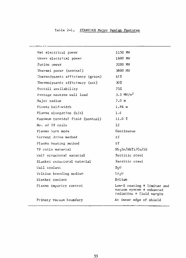
Table 2-1. STARFIRE Major Design Features
Net electrical power
Gross electrical power
Fusion power
Thermal power (nominal)
Thermodynamic efficiency (gross)
Thermodynamic efficiency (net)
Overall availability
Average neutron wall load
Major radius
Plasma half-width
Plasma elongation (b/a)
Maximum toroidal field (nominal)
No. of TF coils
Plasma burn mode
Current drive method
Plasma heating method
TF coils material
Wall structural material
Blanket structural material
Wall coolant
Tritium breeding medium
Blanket coolant
Plasma impurity control
Primary vacuum boundary
1150 MW
1600 MW
3200 MW
3800 MW
41%
30%
75%
3.5 MW/m2
7.0 m
1.94 m
1.6
11.0 T
12
Continuous
rf
rf
Nb3Sn/NbTi/Cu/SS
Ferritic steel
Ferritic steel
D20
Li2O
Helium
Low-Z coating + limiter andvacuum system + enhancedradiation + field margin
At inner edge of shield
55

Table 2-2, STARFIRE Impurity Control
Primary System
Low-Z coating
Limiter and vacuum system
TF margin to permit higher a and sputteredimpurity concentrations
Enhanced radiation to reduce heat transport tolimiter
Backup Option
Bundle divertor
(+ low-Z coating and enhanced radiation)
Major Parameters
Equilibrium impurity concentrations:
VNDT
NBe/NDT = °'04
Effective reflection coefficient for He - 0.70
Surface area of the limiter = 1 5% of firstwall area
Heat transport power to limiter = 115 MW
Maximum power density to limiter 5 A ^
Limiter coolant = water
TF field margin * 1,5 I
Enhanced radiation material = Kr or Xe
Radiated power to first wall * 650 MW
56
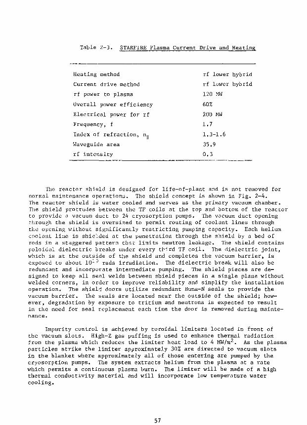
Table 2-3. STARFIRE Plasma Current Drive and Heating
Heating method rf lower hybrid
Current drive method rf lower hybrid
rf power to plasma 120 MW
Overall power efficiency 60%
Electrical power for rf 200 MW
Frequency, f 1.7
Index of refraction, n.. 1.3-1.6
Waveguide area 35.9
rf intensity 0.3
The reactor shield is designed for life-of-plant and is not removed fornormal maintenance operations. The shield concept is shown in Fig. 2-4.The reactor shield is water cooled and serves as the primary vacuum chamber.The shield protrudes between the TF coils at the top and bottom of the reactorto provide a vacuum duct to 24 cryosorption pumps. The vacuum duct openingthrough the shield is oversized to permit routing of coolant lines throughthe opening without significantly restricting pumping capacity. Each heliumcoolant line is shielded at the penetration through the shield by a bed ofrods in a staggered pattern that limits neutron leakage. The shield containspoloidal dielectric breaks under every tbird TF coil. The dielectric joint,which is at the outside of the shield and completes the vacuum barrier, isexposed to about 101° rads irradiation. The dielectric break will also beredundant and incorporate intermediate pumping. The shield pieces are de-signed to keep all seal welds between shield pieces in a single plane withoutwelded corners, in order to improve reliability and simplify the installationoperation. The shield doors utilize redundant Buna-N seals to provide thevacuum barrier. The seals are located near the outside of the shield; how-ever, degradation by exposure to tritium and neutrons is expected to resultin the need for seal replacement each time the door is removed during mainte-nance.
Impurity control is achieved by toroidal limiters located in front ofthe vacuum slots. High-Z gas puffing is used to enhance thermal radiationfrom the plasma which reduces the limiter heat load to 4 MW/ra2. As the plasmaparticles strike the limiter approximately 30% are directed to vacuum slotsin the blanket where approximately all of those entering are pumped by thecryosorption pumps. The system extracts helium from the plasma at a ratewhich permits a continuous plasma burn. The limiter will be made of a highthermal conductivity material and will incorporate low temperature watercooling.
57
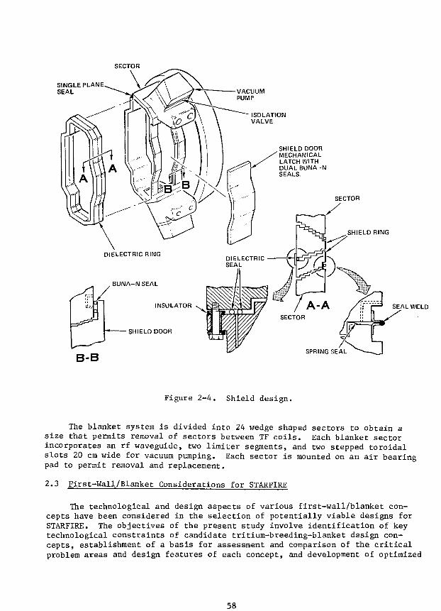
SECTOR
SINGLE PLANESEAL
SHIELD DOORMECHANICALLATCH WITHDUAL BUNA-NSEALS.
SECTOR
SHIELD RING
DIELECTRIC RING
BUNA-N SEAL
INSULATOR
SHIELD DOOR
DIELECTRICSEAL
B-B
SEAL WELD
Figure 2-4. Shield design.
The blanket system is divided into 24 wedge shaped sectors to obtain asize that permits removal of sectors between TF coils. Each blanket sectorincorporates an rf waveguide, two limiter segments, and two stepped toroidalslots 20 cm wide for vacuum pumping. Each sector is mounted on an air bearingpad to permit removal and replacement.
2.3 First-Wall/Blanket Considerations for STARFIRE
The technological and design aspects of various first-wall/blanket con-cepts have been considered in the selection of potentially viable designs forSTARFIRE. The objectives of the present study involve identification of keytechnological constraints of candidate tritium-breeding-blanket design con-cepts, establishment of a basis for assessment and comparison of the criticalproblem areas and design features of each concept, and development of optimized
58
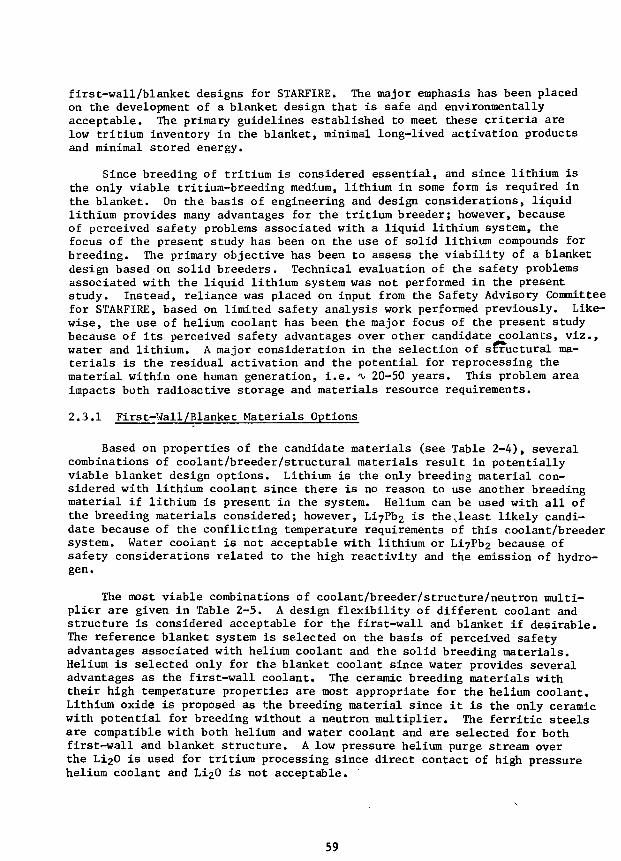
first-wall/blanket designs for STARFIRE, The major emphasis has been placedon the development of a blanket design that is safe and environmentallyacceptable. The primary guidelines established to meet these criteria arelow tritium inventory in the blanket, minimal long-lived activation productsand minimal stored energy.
Since breeding of tritium is considered essential, and since lithium isthe only viable tritium-breeding medium, lithium in some form is required inthe blanket. On the basis of engineering and design considerations, liquidlithium provides many advantages for the tritium breeder; however, becauseof perceived safety problems associated with a liquid lithium system, thefocus of the present study has been on the use of solid lithium compounds forbreeding. The primary objective has been to assess the viability of a blanketdesign based on solid breeders. Technical evaluation of the safety problemsassociated with the liquid lithium system was not performed in the presentstudy. Instead, reliance was placed on input from the Safety Advisory Committeefor STARFIRE, based on limited safety analysis work performed previously. Like-wise, the use of helium coolant has been the major focus of the present studybecause of its perceived safety advantages over other candidate coolants, viz.,water and lithium. A major consideration in the selection of structural ma-terials is the residual activation and the potential for reprocessing thematerial within one human generation, i.e. <\» 20-50 years. This problem areaimpacts both radioactive storage and materials resource requirements.
2.3.1 First-Wall/Blanket Materials Options
Based on properties of the candidate materials (see Table 2-4), severalcombinations of coolant/breeder/structural materials result in potentiallyviable blanket design options. Lithium is the only breeding material con-sidered with lithium coolant since there is no reason to use another breedingmaterial if lithium is present in the system. Helium can be used with all ofthe breeding materials considered; however, Li7Pb2 is the^least likely candi-date because of the conflicting temperature requirements of this coolant/breedersystem. Water coolant is not acceptable with lithium or LiyPb2 because ofsafety considerations related to the high reactivity and the emission of hydro-gen.
The most viable combinations of coolant/breeder/structure/neutron multi-plier are given in Table 2-5. A design flexibility of different coolant andstructure is considered acceptable for the first-wall and blanket if desirable.The reference blanket system is selected on the basis of perceived safetyadvantages associated with helium coolant and the solid breeding materials.Helium is selected only for the blanket coolant since water provides severaladvantages as the first-wall coolant. The ceramic breeding materials withtheir high temperature properties are most appropriate for the helium coolant.Lithium oxide is proposed as the breeding material since it is the only ceramicwith potential for breeding without a neutron multiplier. The ferritic steelsare compatible with both helium and water coolant and are selected for bothfirst-wall and blanket structure. A low pressure helium purge stream overthe Li20 is used for tritium processing since direct contact of high pressurehelium coolant and Li20 is not acceptable.
59
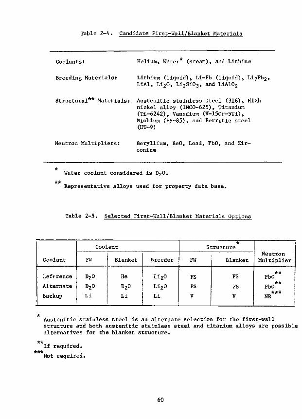
Table 2-4. Candidate First-Wall/Blanket Materials
Coolants: Helium, Water (steam), and Lithium
Breeding Materials: Lithium (liquid), Li-Pb (liquid), Li7Pb2,L1A1, Li2O, Li2Si03, and LiA102
Structural Materials: Austenitic stainless steel (316), Highnickel alloy (INCO-625), Titanium(Ti-6242), Vanadium (V-15Cr-5Ti),Niobium (FS-85), and Ferritic steel(HT-9)
Neutron Multipliers: Beryllium, BeO, Lead, PbO, and Zir-conium
Water coolant considered is D20.
Representative alloys used for property data base.**
Table 2-5. Selected First-Wall/Blanket Materials Options
Coolant
Inference
Alternate
Backup
Coolant
FW
D20
D20
Li
Blanket
He
D20
Li
Breeder
Li2O
Li2O
Li
*Structure
FW
FS
FS
V
Blanket
FS
i'S
V
NeutronMultiplier
**PbO
**PbO***
NR
***
Austenitic stainless steel is an alternate selection for the first-wallstructure and both austenitic stainless steel and titanium alloys are possiblealternatives for the blanket structure.
If required.
Not required.
60
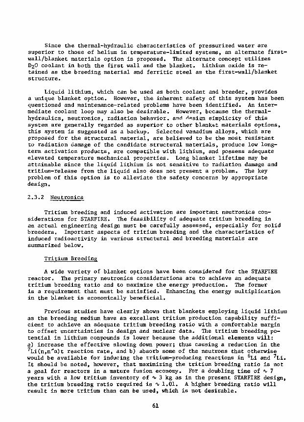
Since the thermal-hydraulic characteristics of pressurized water aresuperior to those of helium in temperature-limited systems, an alternate first-wall/blanket materials option is proposed. The alternate concept utilizesD2O coolant in both the first wall and the blanket. Lithium oxide is re-tained as the breeding material and ferritic steel as the first-wall/blanketstructure.
Liquid lithium, which can be used as both coolant and breeder, providesa unique blanket option. However, the inherent safety of this system has beenquestioned and maintenance-related problems have been identified. An inter-mediate coolant loop may also be desirable. However, because the thermal-hydraulics, neutronics, radiation behavior, and H^sign simplicity of thissystem are generally regarded as superior to other blanket materials options,this system is suggested as a backup. Selected vanadium alloys, which areproposed for the structural material, are believed to be the most resistantto radiation damage of the candidate structural materials, produce low long-term activation products, are compatible with lithium, and possess adequateelevated temperature mechanical properties. Long blanket lifetime may beattainable since the liquid lithium is not sensitive to radiation damage andtritium-release from the liquid also does not present a problem. The keyproblem of this option is to alleviate the safety concerns by appropriatedesign.
2.3.2 Neutronics
Tritium breeding and induced activation are important neutronics con-siderations for STARFIRE. The feasibility of adequate tritium breeding inan actual engineering design must be carefully assessed, especially for solidbreeders. Important aspects of tritium breeding and the characteristics ofinduced radioactivity in various structural and breeding materials aresummarized below.
Tritium Breeding
A wide variety of blanket options have been considered for the STARFIREreactor. The primary neutronics considerations are to achieve an adequatetritium breeding ratio and to maximize the energy production. The formeris a requirement that must be satisfied. Enhancing the energy multiplicationin the blanket is economically beneficial.
Previous studies have clearly shown that blankets employing liquid lithiumas the breeding medium have an excellent tritium production capability suffi-cient to achieve an adequate tritium breeding ratio with a comfortable marginto offset uncertainties in design and nuclear data. The tritium breeding po-tential in lithium compounds is lower because the additional elements will:a) increase the effective slowing down power; thus causing a reduction in the7Li(n,n*a)t reaction rate, and b) absorb some of the neutrons that otherwisewould be available for inducing the tritium-producing reactions in 6Li and 7Li.It should be noted, however, that maximizing the tritium breeding ratio is nota goal for reactors in a mature fusion economy. For a doubling time of i» 7years with a low tritium inventory of 'v 3 kg as in the present STARFIRE design,the tritium breeding ratio required is <x< 1.01. A higher breeding ratio willresult in more tritium than can be used, which is not desirable.
61
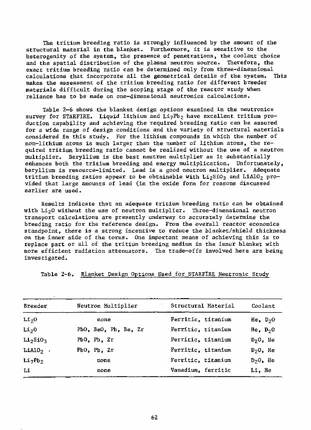
The tritium breeding ratio is strongly influenced by the amount of thestructural material in the blanket. Furthermore, it is sensitive to theheterogenity of the system, the presence of penetrations, the coolant choiceand the spatial distribution of the plasma neutron source. Therefore, theexact tritium breeding ratio can be determined only from three-dimensionalcalculations that incorporate all the geometrical details of the system. Thismakes the assessment of the tritium breeding ratio for different breedermaterials difficult during the scoping stage of the reactor study whenreliance has to be made on one-dimensional neutronics calculations.
Table 2-6 shows the blanket design options examined in the neutronicssurvey for STARFIRE. Liquid lithium and Li7Pb2 have excellent tritium pro-duction capability and achieving the required breeding ratio can be assuredfor a wide range of design conditions and the variety of structural materialsconsidered in this study. For the lithium compounds in which the number ofnon-lithium atoms is much larger than the number of lithium atoms, the re-quired tritium breeding ratio cannot be realized without the use of a neutronmultiplier. Beryllium is the best neutron multiplier as it substantiallyenhances both the tritium breeding and energy multiplication. Unfortunately,beryllium is resource-limited. Lead is a good neutron multiplier. Adequatetritium breeding ratios appear to be obtainable with Li2SiC>3 and LiAlOj pro-vided that large amounts of lead (in the oxide form for reasons discussedearlier are used.
Results indicate that an adequate tritium breeding ratio can be obtainedwith Li20 without the use of neutron multiplier. Three-dimensional neutrontransport calculations are presently underway to accurately determine thebreeding ratio for the reference design. From the overall reactor economicsstandpoint, there is a strong incentive to reduce the blanket/shield thicknesson the inner side of the torus. One important means of achieving this is toreplace part or all of the tritium breeding medium in the inner blanket withmore efficient radiation attenuators. The trade-offs involved here are beinginvestigated.
Table 2-6. Blanket Design Options Used for STARFIRE Neutronic Study
Breeder Neutron Multiplier Structural Material Coolant
Li20
Li20
Li2Si03
LiA102 •
Li7Pb2
Li
PbO,
PbO,
PbO,
none
BeO, Pb, Be, Zr
Pb, Zr
Pb, Zr
none
none
Ferritic,
Ferritic,
Ferritic,
Ferritic,
Ferritic,
Vanadium,
titanium
titanium
titanium
titanium
titanium
ferritic
He,
He,
D20
D20
D20
Li,
D20
D20
, He
, He
, He
He
62
Reactor Activation
The requirement of achieving an environmentally acceptable reactor con-cept must be taken into account early in the design effort. The major safetyand environmental impacts of fusion power reactors, as envisioned today, areassociated with the inventories of radioactive tritium and neutron inducedactivation of reactor components. In order to incorporate such safety andradiological issues into the design considerations, a careful considerationhas been devoted to a prudent selection of breeding material, coolant andstructural material.
The computation for the radioactivity and radioactivity-related parameterssuch as biological hazard potential (BHP), and decay 8/y spectrum has beenperformed by using the RACC8 code in conjunction with the HACCDLIB/RACCXLIBdata libraries.
Effect of Structural Materials on Reactor Activation
Figure 2-5 shows a comparison of the candidate structural materials interms of biological hazard on inhalation (BHP air) as a function of timeafter reactor shutdown following a two year reactor operation. Over the timeperiod from 5 years to 50 years after shutdown, the two different ferriticsteel systems (FS-CE and FS-X) show a factor of 10-50 lower BHP than the316 stainless steel alloy. Over the same time period, the BHP in the Ti4381system is further reduced by approximately one to two orders of magnitudefrom those for the FS systems. Because of the similarity of the isotope con-tents in the Ti4381 and V15CrTi alloys, the general trend of BHP variationin the both systems is almost identical, keeping about a factor of 10 differ-ence in their absolute magnitudes over the entire time span under considera-tion.
A comparison of BHP's in each reactor component for the candidate breedersystems has been made. The structural material is assumed to be ferriticstainless steel (FS-X) throughout the reactor systems. With regard to thecoolant, a helium gas is used in all cases except for the liquid lithiumblanket which is also cooled by the lithium fluid. It is found that theBHP's in the whole system, as well as in each component, do not vary to anyappreciable degree from one breeder system to another. The total BHP's forall the systems are bracketed within a maximum difference of a factor of 2at each time point over the time span of 0-100 yr. However, it should benoted that the results obtained here are very dependent upon the structuralmaterial chosen. In the case of FS-X, the effect of spectrum change (re-sulting from use of a different breeder material and/or PbO multiplier)on the BHP's tends to be less significant simply due to the large BHP ofthe structural material itself.
2.3.3 Tritium and Safety Considerations for the First Wall and Blanket
A comprehensive study of various structure/breeder/coolant systems hasrecently been completed wherein details of experiments investigating potentialfusion breeders and coolants are discussed,-^ and hence, will not be
63
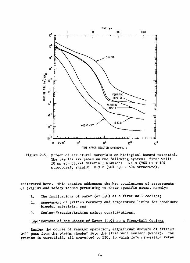
TIME, jrs10 100 1000
"= 10
10-* 5-V-15 Cr-5Ti
0 2»IO7 10* JO9 I010 10"
TIME AFTER REACTOR SHUTDOWN, s
Figure 2-5. Effect of structural materials on biological hazard potential.The results are based on the following system: first wall:10 mm structural material; blanket: 0.6 m (90% Li + 10%structure); shield: 0.9 m (50% B4C + 50% structure).
reiterated here. This section addresses the key conclusions of assessmentsof tritium and safety issues pertaining to three specific areas, namely:
1. The implications of water (or D2O) as a first wall coolant;
2. Assessment of tritium recovery and temperature limits for candidatebreeder materials; and
3. Coolant/breeder/tritium safety considerations.
Implications of the Choice of Water (D?0) as a First-Wall Coolant
During the course of reactor operation, significant amounts of tritiumwill pass from Che plasma chamber into the first wall coolant (water). Thetritium is essentially all converted to HTO, in which form permeation rates
64

are very small ( « 0.1 Ci/day) and tritium is not lost only to the extent thatthe coolant water itself is physically lost. Thus, water is a sink for tritium.Permeation rates for tritium passing from the plasma chamber through theferritic steel tube wall into the first wall coolant have been calculatedfor various conditions.
For conditions anticipated in systems with a water-cooled first walland/or blanket, tritium levels are estimated to be 2 to 100 Ci/2.. As a pointof reference, 20 Ci/it is typical of the level in the moderator of a heavywater reactor (HWR) after many years of operation, however, some control isimplemented to maintain this level. This level gives H/T ratios on the orderof 105 in the water and requires an enrichment of at least six orders ofmagnitude before one can consider returning the tritium to the fuel cycle.
The use of D2O as a coolant offers a significant advantage over H2Obecause deuterium is a fuel, and therefore, isotopic enrichment requirementsare relaxed. For example, the tritium could be recovered in a 99% deuteriummixture, requiring enrichment factors of <v 103, which is three orders ofmagnitude lower than required for light water. Separation factors will besomewhat lower for D2O, but this is a comparatively small effect. Also,for STARFIRE, 2000 Ci/yr will be generated in the D2O coolant from neutronactivation of the deuterium. This amount is less than that for inleakagefrom the plasma. Although hydrogen permeation from the coolant through thefirst wall could affect the plasma performance, deuterium permeation willpresent no problem. All factors considered, it appears that D2O is muchpreferred over H2O as a coolant.
There are three potential operating scenarios for a water coolant cir-cuit on STARFIRE: (i) allow tritium to build up until the decay rate equalsthe migration rate, providing the steady-state level is 20 Ci/Jl; (ii) pro-vide sufficient in plant enrichment capacity to maintain the level at i> 20Ci/2. (if the migration rate is too high) and dispose of the tritium-richfraction; and (iii) provide sufficient in-plant enrichment to recover allmigrating tritium for recycle to the reactor fueling systems. Clearly, thelast of these options is to be preferred.
Assessment of Tritium Recovery and Temperature Limits for CandidateBreeder Materials
In a fusion blanket, the concentration in the solid breeder will buildup until the rate of diffusion out of the solid is equal to the tritiumgeneration rate, and steady state is achieved.
The calculated tritium inventories for candidate solid breeders areshown in Fig. 2-6. In view of the very strong temperature dependence andthe fact that the inventory is extremely sensitive to the diffusion pathlength r (I « r 2), it is not surprising that some analyses conclude thatsolids will have very low tritium inventories, while others conclude thatsolids may have very high inventories.
The design solution to this dilemma is proper temperature control. Theminimum temperature must be sufficiently high that tritium will diffuse out
65
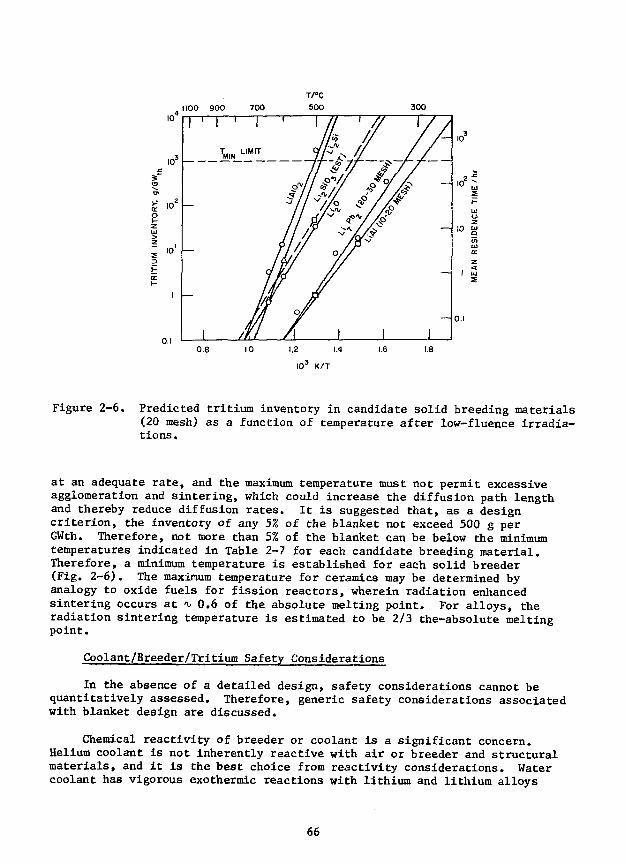
, 1100 900 300
1.8
Figure 2-6. Predicted tritium inventory in candidate solid breeding materials(20 mesh) as a function of temperature after low-fluence irradia-tions .
at an adequate rate, and the maximum temperature must not permit excessiveagglomeration and sintering, which could increase the diffusion path lengthand thereby reduce diffusion rates. It is suggested that, as a designcriterion, the inventory of any 5% of the blanket not exceed 500 g perGWth. Therefore, not more than 5% of the blanket can be below the minimumtemperatures indicated in Table 2-7 for each candidate breeding material.Therefore, a minimum temperature is established for each solid breeder(Fig. 2-6). The maximum temperature for ceramics may be determined byanalogy to oxide fuels for fission reactors, wherein radiation enhancedsintering occurs at t, 0.6 of the absolute melting point. For alloys, theradiation sintering temperature is estimated to be 2/3 the-absolute meltingpoint.
Coolant/Breeder/Tritium Safety Considerations
In the absence of a detailed design, safety considerations cannot bequantitatively assessed. Therefore, generic safety considerations associatedwith blanket design are discussed.
Chemical reactivity of breeder or coolant is a significant concern.Helium coolant is not inherently reactive with air or breeder and structuralmaterials, and it is the best choice from reactivity considerations. Watercoolant has vigorous exothermic reactions with lithium and lithium alloys
66

Table 2-7. Temperature Limits (°C) for Solid Breeders
Breeder m.p. °C
Li2O 17005
LiA102 1610
Li2Si03 12006
Li2Si 760
LiAl 700
Li7Pb2 726
Thermal Effects
min
410
500
420
480
300
320
I 2
max
1000
1000
900
550
500
530
Radiation Effects
T 3
min
460
550
470
530
350
370
T 4
max
910
850
610
420
380
390
Diffusion limited.2Thermal sintering.
Radiation-induced trapping (factor of 10 degradation in tritium release estimated),
Radiation enhanced sintering (0.6 T for oxides and 0.67 T for othercompounds) .
Li20 reportedly sublimes at temperatures below the melting point.
Li2Si03 is a line compound with a solidus temperature of 1030°C for slightlyhypo- or hyperstoichiometric compositions.
to the extent that these breeder/coolant combinations are not consideredviable. Water coolant should have only modest reactions with Li20 (orother oxides) at elevated temperatures. Cleanup of reaction products andcorrosion of the structural materials by LiOH pose the major problems with thissystem. The reactivity of lithium with water, air, and concrete and theassociated accident scenarios and cleanup problems are matters of significantconcern.
Coolant pressure is a significant safety concern. Pressurized waterand helium would both have pressures considerably higher than liquid lithium.
Tritium safety implications are concerned with tritium inventories andthe chemical form of tritium. Because tritium is not a radiation hazard,but is an assimilation hazard, the more absorbing' oxidized form (T20 or HTO)has a significantly higher biological hazard than does T2. Coolant inven-tories will be lower ( 1 g) for He or water, but the tritium will be in
67
the oxidized form. In the liquid lithium case, the tritium inventory in thecoolant will be the blanket inventory, i.e., <v 100 g.
2.3.4 Mechanical Design of First Wall/Blanket
First-wall/blanket mechanical design concepts are being developed for theselected reference and alternate materials options. This section discussesrationale for the selection of the design concepts for the reference helium-cooled and alternate water-cooled blanket choices, presents the concepts anddiscusses their relative merits. The design concept for the backup lithium-cooled blanket is also described briefly.
The reference and alternate design concepts are presently being developedand analyzed further to assure that design requirements are satisfied in theareas of thermal hydraulics, power cycle efficiency, tritium breeding, tritiumrecovery, fabricability, and structural integrity, and to determine how wellthey satisfy the design objectives. The concepts will subsequently be comparedand the final choice made for the reference first wall/blanket materials combi-nation and mechanical design concept.
The overall approach to mechanical design of the first wall/blanket sys-tem is similar for both the reference and alternate materials options. Themost important objectives for the designs were to:
• minimize probability/consequences of accidental contact ofincompatible materials;
• maximize reliability of system and components, to increase avail-ability;
• maximize maintainability by minimizing need for, and time requiredfor, standard maintenance operations;
• minimize inboard wall and blanket thickness, to reduce reactor sizeand maximum magnetic field; and
• minimize outboard wall and blanket thickness, to minimize TF andEF coil size.
Selection of the mechanical design concept for the reference heliumcooled blanket and the alternate water cooled blanket is strongly dependenton the individual and combined characteristics of the selected structural ma-terial, coolant and breeder. Of critical importance is assuring satisfactoryadherence to minimum and maximum temperature constraints placed on the solidbreeders. For the helium cooled design, minimizing the blanket thickness,manifold and header size were also of major importance, in order to minimizerequired reactor size.
Both the reference and alternate designs use the concept of individualblanket modules of similar shape and size which are built up into first wallwedge-shaped blanket circumferential sectors. This approach has severaladvantages. It permits more accurate tailoring of the blanket to match neu-tron wall load values at specific positions around the plasma cross section.
68

Accommodation of local discontinuities such as vacuum ports and rf ducts issimplified. Replacement of individual modules can be performed in the hotcell, while the reactor is returned to normal operation following installationof a replacement sector. The reactor is thus shut down only for the timeneeded t_o remove the sector containing a faulty first wall or blanket compo-nent and to install the replacement sector.
A water-cooled first wall, mechanically and structurally separate fromthe blanket, was selected for both the reference and alternate concepts. Firstwall design life is expected to be significantly less than that of the blanket.The separate first-wall concept permits simple replacement (in the hot cell)of a failed first-wall panel without also requiring replacement of the moreexpensive and longer lived blanket module behind it. The use of water coolantfor the first wall in the reference design permits accommodation of the se-lected neutron wall load (P ) value of 3.5 MW/m2 with negligible pumpinglosses. The two additional disconnect/reconnect operations for the firstwall water coolant headers, necessary for removal of a reference blanketsector, are not considered a major addition to the time required for thatoperation.
The reference first wall/blanket design features a helium cooled blanket.Lithium oxide (Li20) is used to breed tritium, which is removed continuouslyfrom the breeder through a helium purge gas system. The breeder is sealed toprevent contact with the helium coolant stream. Ferritic steel alloy isthe baseline structural material for the blanket and the first wall. Thefirst wail is water cooled and separate from the blanket.
Two mechanical design concepts are being considered for the referenceblanket. In the first concept, the module walls are pressurized to thecoolant static pressure. The solid breeder is held in sealed tubes, arrangedin a staggered rod bank pattern, which are cooled by cross-flowing the heliumover them. In the second concept, the helium coolant flows inside tubes eachof which is surrounded by solid breeder throughout the module. The two con-cepts will be compared in the near future after further evaluation to deter-mine which is superior from an over.ill reactor design standpoint.
The first wall concept for the reference design is essentially a watercooled flat panel. Tl:e basic concept is common to both the reference andalternate blanket concepts. Details of the design will be developed laterin the study. For the present, the mechanical design concept used is thatadopted previously in the ANL-EPR study.^ In this design, cooling isaccomplished by circulating pressurized water in a network of channels thatline the plasma side of the panel. The channels are formed by bonding a pre-formed steel sheet to a second, flat steel sheet. Each panel section spansseveral blanket modules, and has one inlet and one outlet coolant line whichconnect to manifolds at the rear of the blanket module. These manifoldsconnect all first wall panels and the water cooled inboard blanket withina single blanket sector. The manifolds terminate in headers in the vicinityof the helium blanket coolant headers, and are in turn attached mechanicallyto inlet and outlet feed pipes which remain in the reactor when the sectorif. removed.
69

2.4 Maintenance of STARFIRE
Maintenance Approach
The ability to maintain the STARFIRE reactor rapidly with a minimum ofradiation exposure to maintenance personnel the key to its acceptance by theutilities and public.
The remote maintenance approach was chosen for in-reactor operations be-cause of the likelihood that current regulatory radiation limits will besignificantly reduced and because the reactor hall will be exposed to tritiumby permeation and releases during maintenance of the coolant, fueling, vacuumand tritium systems. Some activation may also result from neutron streaming.Use of remote equipment will permit maintenance with a minimal cool-down orclean—up period.
The design philosophy being followed is to minimize the radiation levelswithin the reactor building; to design all components for completf -notemaintenance, and to identify contact maintenance operations where onnelcan safely be used with significant economic savings.
All components within the reactor building are replaceable. Some arereplaced on a scheduled maintenance basis while others are designed for thelife of the plant and are replaced only in the event of failure. Items de-signed for the life of the plant include the overhead crane, TF coils, EFcoils, coolant piping, reactor support structure and radiation shielding.The blanket assembly, impurity control components, rf launchers, pumpsT valves,fueling mechanism, power supplies, etc. are replaced on a scheduled basis.Spares are provided for all components witi. expected high failure rates, sothat as one part is removed a pretested replacement is available so reactoroperation can commence while repairs to the damaged components are beingmade. The spares for the superconducting EF coils trapped below the TF coilsare stored in place so reactor disassembly is unnecessary in event of afailure. These coils are designed for life of plant but the consequence oftheir failure suggests in place spares are prudent.
The number of different maintenance operations planned in the reactorbuilding are minimized by using a component "remove and replace" approach.This permits each maintenance action to be preplanned and designed for usewith simple push, pull, etc., operations. This approach increases the confi-dence in the speed of maintenance operations and simplifies maintenanceequipment design requirements. Once the damaged or end-of-life componentsare removed from the reactor, they are transported to a hot cell where moretime is available for checkout, repair or disposal. The hot cell will haveextensive maintenance capability for testing, component replacement, cutting,welding, machining, pinpoint leak location, and low-Z coating repair.
Redundancy is planned for reactor auxiliary subsystems to permit con-tinued operation of the plant until a scheduled maintenance period or until
70
the component can be replaced in-service. The particular components whereredundancy is planned will be defined as the design progresses; however,current plans include redundant power supplies, vacuum pumps, rf launchers,some valves, pumps and fueling mechanisms.
Availability goals have been established as 85% for the reactor and 75%for the complete plant including the reactor. Allocations of permissibletime-to-repair and time-between-failures have been made for major subsystemsto serve as a basis for design of the components and maintenance equipment.The maintenance scenario incorporates the current utility practice of shuttingdown annually for one month of maintenance and a 4 to 5 month shutdown every5 to 10 years for turbine repair. The resultant permissible downtime goalper calendar year has been allocated as 30 days for scheduled maintenanceof the entire plant, 21 days for unscheduled maintenance of the balance-of-plant and A0 days for unscheduled maintenance of the reactor, auxiliarysubsystems and maintenance equipment. Convenient preventative maintenanceand repair of redundant components is included as part of the maintenancescenario during these unscheduled outages.
Maintenance Features
The design is being developed to keep the top and sides of the reactorclear for access by maintenance equipment. Components are also being combinedwhere practical to minimize the number of subassemblies and improve access.Examples of combined components include; the TF coil room-temperature dewarand shield provides the EF and TF magnet structural support system; and therf system provides startup and plasma current drive functions.
The blanket is replaceable as a 1/24 sector of the torus. Each 1/24sector incorporates an integral first wall, liuiiter, rf duct and air bearingpad that is removed with the blanket. The coolant is manifolded throughseparate loops for each l/24th of the reactor to permit leak isolation toindividual sectors. The helium coolant lines and the water coolant linesto the rf duct and limiter utilize mechanical disconnects. The life goalfor limiter and rf duct is 4 years and the blanket life goal is 8 years.After four years the blanket sector is replaced. The used sector is refur-bished in the hot cell by replacing the limiter, rf duct and low-Z coating.Periodic in-situ replacement of the low-Z coating may also be required.
Blanket module leak detection will be accomplished by sequentially re-ducing the pressure in individual blanket sectors and monitoring the changeof the partial pressure of helium in the plasma chamber with a gas analyzer.This technique requires valves that isolate sectors from the primary coolantloop. Leak detection of the limiter first wall and rf launcher water systemwill also rely on reducing the system pressure of each sector sequentiallyand denoting changes in the detected leak rate. Leak detection of the shieldsystem to the plasma chamber system will be accomplished by injecting heliuminto a cavity between redundant seals. The blanket leak detection systemis dependent on the particular design that is developed and will be modifiedas necessary.
71
The shield is designed to last the life-of-plant and will be replacedonly in event of unscheduled failures. A shield door is provided thatpermits access to the blanket. The door is sealed with redundant sealsthat are shielded locally to reduce the radiation damage. The seals arereplaced each time the door is opened. The basic shield consists of sectorswelded together to form the vacuum boundary. Cutting and rewelding thepoloidal seals is required if shield sector replacement is required.
The TF coils are also life-of-plant components. They utilize a commonwelded dewar in the center post region. Coil replacement time is not signifi-cantly impacted by the welded dewar. Annealing of the TF coil is plannedevery 10 years to reduce the effects of radiation damage in the stabilizer.
The EF coils are also life-of-plant. EF coils inside the TF coil arecopper and are segmented to permit removal. An elevation system is providedto raise and lower the outer coils for access to the blanket. The externalEF coils are superconducting. Those on the top and sides of the reactor canbe removed for replacement. Spare EF coils are provided for those trappedbelow the TF coils. In event of failure the coil is cut out and the spareraised into position.
The vacuum system utilizes redundancy to improve the probability ofcontinuous operation between scheduled maintenance periods. Twenty-fourcryosorption pumps with isolation valves are provided of 'hich approximately20 are required for operation. External valves and pumps leading to thetritium processing system utilize redundancy.
The power supplies are assumed fully redundant and include a replacementcapability during operation. The power supply systems are located outsidethe primary confinement building and can be repaired during plant operation.
Maintenance Time Allocations
A preliminary listing of the scheduled maintenance actions is shown inTable 2-8. The assumed critical path is shown with the presumption thatall other maintenance actions can be accomplished in parallel operations.This listing will be updated as the program progresses.
The unscheduled maintenance item listing is shown in Table 2-9. Thevalues shown for Mean-Time-To-Replace (MTTR) are assumed values based on paststudies. The average downtime per year is then assigned to each subsystembased on the perceived relative reliability and complexity of each subsystem.The result is a permissible failure rate per calendar year. These values canthen be used by subsystem designers to define the redundancy and design marginrequirements for the subsystems. An accurate assessment of the actual failurerates can only be derived after subsystems are defined as to the number ofcomponents, redundancy provisions, the types of failure modes and failure rateper failure mode have been established. Our program will utilize historicaldata where possible to assess feasibility of meeting the requirements ofTable 2-9.
72
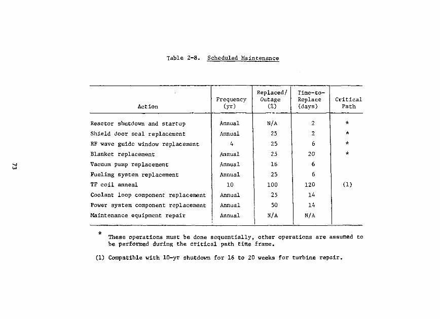
Table 2-8. Scheduled Maintenance
Action
Reactor shutdown and startup
Shield door seal replacement
RF wave guide window replacement
Blanket replacement
Vacuum pump replacement
Fueling system replacement
TF coil anneal
Coolant loop component replacement
Power system component replacement
Maintenance equipment repair
Frequency(yr)
Annual
Annual
4
Annual
Annual
Annual
10
Annual
Annual
Annual
Replaced/Outage
(%)
N/A
25
25
25
16
25
100
25
50
N/A
Time-to-Replace(days)
2
2
6
20
6
6
120
14
14
N/A
CriticalPath
*
*
*
*
(1)
These operations must be done sequentially, other operations are assumed tobe performed during the critical path time frame.
(1) Compatible with 10-yr shutdown for 16 to 20 weeks for turbine repair.
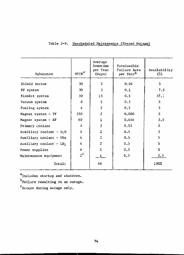
Table 2-9. Unscheduled Maintenance (Forced Outage)
Subsystem
Shield sector
RF system
Blanket system
Vacuum system
Fueling system
Magnet system - TF
Magnet system - EF
Primary coolant
Auxiliary coolant - HgO
Auxiliary coolant - GHe
Auxiliary coolant - LN2
Power supplies
Maintenance equipment
Total:
MTTRa
30
30
30
6
4
350
60
4
4
4
4
4
2C
AverageDowntimeper Year(days)
2
3
15
2
2
2
1
2
2
2
2
2
1
40
PermissibleFailure Rateper Year''
0.04
0.1
0.5
0.3
0.5
0.006
0.016
0,03
0.5
0.5
0.5
0.5
0,5
Availability(%)
5
7,5
37.:
5
5
5
2.5
5
5
5
5
5
2.5
100%
Includes startup and shutdown.
Failure resulting in an outage.
Occurs during outage only.
74
3.0 FUSION SYSTEMS ENGINEERING
3.1 Systems Studies
3.1.1 Technology Development Impact on the Choice of Fusion Fuel Cycles*
C. C. Baker, A. Bolon, R. Clemmer, K. Evans, Jr., J. Jung, L. Turner,Fusion Power Program, and T. Blue, * D. Driemeyer, J. Metzger,**and G. Miley**
General considerations for the study of the technology considerationsof alternate fuel cycles are described below. Basic considerations regardingtokarnaks and field-reversed mirrors are also included. Further considerationsregarding neutronics, fuel processing systems and safety considerations arealso reported. Additional results are also reported regarding the applicationof neutronic computer codes to cyclotron radiation transport.
3.1.1.1 Fuel Cycles and Confinement Concepts
In order to study "representative" combinations that are illustrativeof a wide variety of possible combinations, we have selected for study amatrix of alternate fuels along with a modest and high 8 confinement systems.Since catalyzed-D is the only "self-sufficient" (only requires naturally avail-able deuterium) low-temperature fuel, it is selected as the base fuel. How-ever, due to its potential attractiveness, D-3He is also considered despitethe complication of 3He breeding. Since tokamaks are presently the mosthighly developed confinement system, and since they (or at least modest 6versions) can burn these low temperature fuels, they are selected as a repre-sentative modest (3 (10-20%) confinement system. (These 6 values are about afactor of two larger than predicted by most current theories, but are con-sidered to be reasonable extrapolations for purpose of the study.) Concurrently,the Field-Reversed Mirror (FRM) is selected as a representative high-0 (> 70%)device. This is acceptable for the low-temperature fuels, but may not beadequate for the higher temperature fuels where even more innovative confine-ment approaches such as Surmac may be necessary.
3.1.1.2 Typical Power Splits
Table 3-1 presents the power splits for the reference semi-catalyzed D,fully catalyzed D, and D-3He tokamaks. Note that the fraction of power inneutrons is less by almost an order of magnitude for D-3He than for semi-catalyzed D. The fraction of power in neutrons is less by about 10% forfully-catalyzed D than for semi-catalyzed D. This is, of course, because thefusion product 3He is burned in the fully-catalyzed D reactor.
For purposes of technology considerations discussed in the next section,the most important parameter is the fraction of total power carried by neu-trons. This is relatively constant for the various cases discussed above,
On leave from the University of Missouri - Rolla.**University of Illinois, Urbana, Illinois.
75
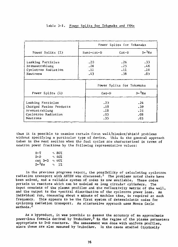
Table 3-1. Power Spiles for Tokamaks and FRMs
Power Spl i t s (Z)
Leaking Par t i c lesBremsstrahlungCyclotron RadiationNeutrons
Power Spl i t s for
Semi-cat-D Cat-D
.20
.26
.11
.43
Power Sp l i t s (%)
Leaking Par t ic lesCharged Fusion ProductsBremsstrahlungCyclotron RadiationNeutrons
Power Spl i t s
Cat-D
.25
.19
.18
.03
.35
.26
.25
.11
.38
for
Tokamaks
D-5He
.33
.46
.16
.05
Tokamaks
D-3He
.24
.39
.26
.08
.03
thus it is possible to examine certain first wall/blanket/shield problemswithout specifying a particular type of device. This is the general approachtaken in the next section when the fuel cycles are characterized in terms ofneutron power fractions by the following representative values:
D-TD-Dc a t D-DD- 3He
-v 80%^ 40%-v. 40%"\/ 1%
In the previous progress report, the possibility of calculating cyclotronradiation transport with ANISN was discussed.-*- The problems noted there havebeen solved, and a reliable system of codes is now available. These codespertain to reactors which can be modeled as long circular cylinders. Theinput consists of the plasma profiles and the reflectivity matrix of the wall,and the output is the •spectral distribution of the cyclotron power loss. Anindividual run, consuming about a minute of machine time, is required at eachfrequency. This appears to be the first system of deterministic codes forcyclotron radiation transport. An alternative approach uses Monte Carlomethods.
As a byproduct, it was possible to assess the accuracy of an approximatepower-loss formula derived by Trubnikov,^ in the regime of the plasma parametersappropriate to D-D reactors. The assessment was done with uniform profiles,since these are also assumed by Trubnikov. In the cases studied (typically
76
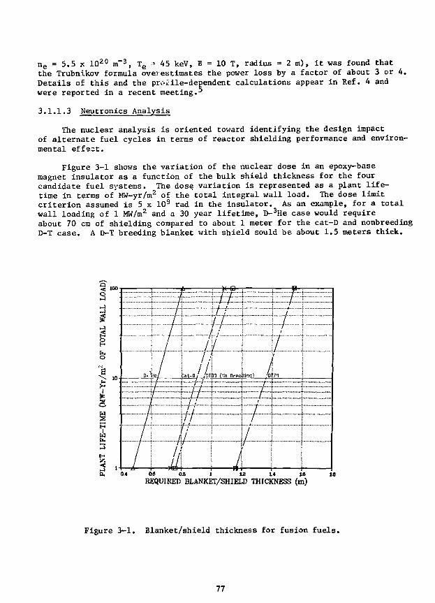
n e = 5.5 x 10²⁰ m~3, Te = 45 keV, B = 10 T, radius = 2 m), it was found that
the Trubnikov formula overestimates the power loss by a factor of about 3 or 4.Details of this and the profile-dependent calculations appear in Ref. 4 andwere reported in a recent meeting•
3.1.1.3 Neutronics Analysis
The nuclear analysis is oriented toward identifying the design impactof alternate fuel cycles in terms of reactor shielding performance and environ-mental effect.
Figure 3-1 shows the variation of the nuclear dose in an epoxy-basemagnet insulator as a function of the bulk shield thickness for the fourcandidate fuel systems. The dose variation is represented as a plant life-time in terms of MW-yr/m2 of the total integral wall load. The dose limitcriterion assumed is 5 x 10⁹ rad in the insulator. As an example, for a totalwall loading of 1 MW/m2 and a 30 year lifetime, D-3He case would requireabout 70 cm of shielding compared to about 1 meter for the cat-D and nonbreedingD-T case. A D-T breeding blanket with shield sould be about 1.5 meters thick.
Q
O
>
2,
w3
d,
13
(Ho flreeiidinqi
T..'DT71
I...0.6 0.8 1 12 14 16REQUIRED BLANKET/SHIELD THICKNESS (m)
Figure 3-1. Blanket/shield thickness for fusion fuels.
77
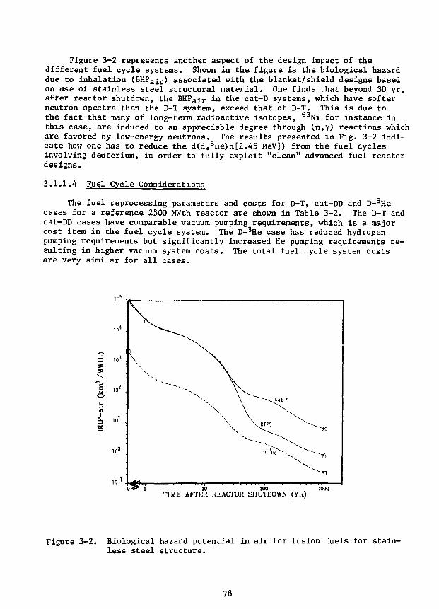
Figure 3-2 represents another aspect of the design impact of thedifferent fuel cycle systems. Shown in the figure is the biological hazarddue to inhalation (BHPair) associated with the blanket/shield designs basedon use of stainless steel structural material. One finds that beyond 30 yr,after reactor shutdown, the BHPair in the cat-D systems, which have softerneutron spectra than the D-T system, exceed that of D-T. This is due tothe fact that many of long-term radioactive isotopes, 63Ni for instance inthis case, are induced to an appreciable degree through (n,Y) reactions whichare favored by low-energy neutrons. The results presented in Fig. 3-2 indi-cate how one has to reduce the d(d,3He)a[2.A5 MeV]) from the fuel cyclesinvolving deuterium, in order to fully exploit "clean" advanced fuel reactordesigns.
3.1.1.4 Fuel Cycle Considerations
The fuel reprocessing parameters and costs for D-T, cat-DD and D-3Hecases for a reference 2500 MWth reactor are shown in Table 3-2. The D-T andcat-DD cases have comparable vacuum pumping requirements, which is a majorcost item in the fuel cycle system. The D-3He case has reduced hydrogenpumping requirements but significantly increased He pumping requirements re-sulting in higher vacuum system costs. The total fuel ycle system costsare very similar for all cases.
10=
IS in2
'3i
pa
in"b ^ i ib
\
V\ \ \\_DT70
100 1000TIME AFTER REACTOR SHUTDOWN (YR)
Figure 3-2. Biological hazard potential in air for fusion fuels for stain-less steel structure.
78
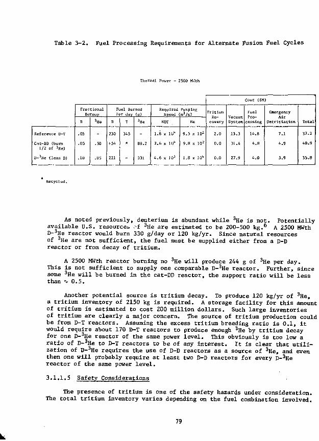
Table 3-2. Fuel Processing Requirements for Alternate Fusion Fuel Cycles
Thermal Power - 2500 MKth
Reference D-T
Cat-DD (burn1/2 of 3He)
D-3He (lean D)
FractionalBurnup
D
.05
.05
.10
3He
-
.50
.05
Fuel BurnedPer day (g)
D
230
(•54
221
T
345
*
-
3He
-
89.2
331
Required PumpingSpeed (m3/s)
HDT
1.8 x 10"
2.6 x 10"
4.6 x ]03
He
9.5 x 10²
9.8 x 10²
1.8 x JO*
Cost ($M)
TritiumRe-covery
2.0
0.0
0.0
VacuumSystem
13.3
31.4
27.9
FuelPro-
cessing
14.8
4.8
4.0
EnergencyAir
Detritiation
7.1
4.9
3.9
Total
37.2
40.9
35.8
Recycled.
As noted previously, deuterium is abundant while 3He is not. Potentiallyavailable U.S. resources of 3He are estimated to be 200-500 kg.6 A 2500 MWthD-3He reactor would burn 330 g/day or 120 kg/yr. Since natural resourcesof 3He are not sufficient, the fuel must be supplied either from a D-Dreactor or from decay of tritium.
A 2500 MWth reactor burning no 3He will produce 244 g of 3He per day.This is not sufficient to supply one comparable D-3He reactor. Further, sincesome 3He will be burned in the cat-DD reactor, the support ratio will be lessthan -v 0.5.
Another potential source is tritium decay. To produce 120 kg/yr of 3He,a tritium inventory of 2150 kg is required. A storage facility for this amountof tritium is estimated to cost 200 million do3.1ars. Such large inventoriesof tritium are clearly a major concern. The source of tritium production couldbe from D-T reactors. Assuming the excess tritium breeding ratio is 0.1, itwould require about 170 D-T reactors to produce enough 3He by tritium decayfor one D-3He reactor of the same power level. This obviously is too low aratio of D-3He to D-T reactors to be of any interest. It is clear that utili-zation of D-3He requires the use of D-D reactors as a source of 3He, and eventhen one will probably require at least two D-D reactors for every D-3Hereactor of the same power level.
3.1.1.5 Safety Considerations
The presence of tritium is one of the safety hazards under consideration.The total tritium inventory varies depending on the fuel combination involved.
79
A typical 2500 MWth D-T system would require 8000 g of tritium inventory,cat-DD 100 g, and D-3He only 10 g. Of those totals the amount of tritiumconsidered to be vulnerable is 2000 g for D-T, about 20 g for cat-DD andabout 2 g for D-3He. The vulnerable positions are that part of the tritiumwhich could conceivably be released in the case of an accident. Even withinventories as low as a few grams, some type of emergency tritium cleanupsystem will be required.
The induced radxoactivities in the first wall and the structural ma-terials in the blanket and shield are the other major sources of radioactivitypresently being considered. Several candidate materials have been consideredfor all three fuel systems. The candidate materials considered are 316stainless steel, Ti-4381 and V-15Cr-5Ti alloys. The normalized activities(Ci/MWth) of these alloys have been calculated for preliminary alternatefuels design conditions both during reactor operation (from 1 second to 2 years)and following reactor shutdown (from time zero to 1000 years).
The amospheric (x/Q) dispersion of tritium and of structural materialwas examined for a hypothetical accident based on a short-term uniform re-lease from a point source. A simple model is utilized in order to comparethe relative external dose from the candidate alloys dispersed in a Gaussianplume. The impact of tritium leaking from the reactor building following ahypothetical accident was also calculated using the same methodology.
The relative external doses due to a given structural material indifferent advanced fuel systems being volatized by a hypothetical reactor 'accident and its leaking out of containment is shown for 316 stainless steelin Fig. 3-3. The same information could have been plotted for the othercandidate materials, but they are generally similar, except the values areapproximately an order of magnitude lower for the vanadium alloy.
Based on the results, the cat-DD system produces higher total externaldoses following a hypothetical accident than does a D-T system; while theD-3He system produces much lower doses. The relative doses for D-T comparedto D-3He are about 10 times as great for 316 SS, 35 times for the vanadiumalloy and about 60 times for the titanium alloy. The impact of the absolutevalue of these doses relates to the size of exclusion boundary that would berequired around a fusion power plant.
The relative effect of the vulnerable tritium inventory in the reactorbuilding was also calculated for each of the advanced fuels systems. Thenormalized activities of tritium would be 7.7 x 10³ Ci/MWth for D-T, 77 Ci/MWthfor cat-DD, and 7.7 Ci/MWth for D-3He. The activity of tritium when comparedto the activity of structural material is generally quite small. The externalwhole body tritium doses from the plume at 200 meters from the reactor andat one hour following an accident would be 1.9 x 10~9 rem/s-MWth for D-T,1.9 x 10~ n for cat-DD, and 1.9 x 10~12 for D-3He. The whole body doses dueto tritium compared to the doses due to structural materials are small (onthe order of 0.10 percent).
80

10 10" 10"DISTANCE FROM REACTOR, m
Figure 3-3. Relative external doses for alternate fuel system.
3.2 Tritium Processing and Control
3.2.1 Development of Processing Technology for D-T Fusion Reactor BreederBlankets
The program underway in the Chemical Engineering Division to developprocessing technology for D-T fusion reactor breeder blankets is continuing.Progress during spring to fall calendar 1979 is summarized below:
3.2.1.1 Liquid Lithium Processing Studies
J. R. Weston, W. F. Calaway and V. A. Maroni, Chemical EngineeringDivision
The Lithium Processing Test Loop (LPTL) was shut down for scheduledmaintenance in late August, 1979 after ^ 9500 hours of operation. Duringthe shutdown several heaters on the reservoir tank were replaced. Also,the valve leading to the getter trap (which had previously developed abellows leak) was cut out and a pipe section was welded in its place. OnOctober 4, 1979, the LPTL was restarted. Following the initiation of flow,there was evidence of some increased resistance to liquid movement in thepiping system, but a stable temperature profile was achieved. On the followingday (October 5, 1979) at 12:40 p.m., a pipe rupture developed in the centerof the EM-pump channel, which caused a spray-type release of lithium. The
81
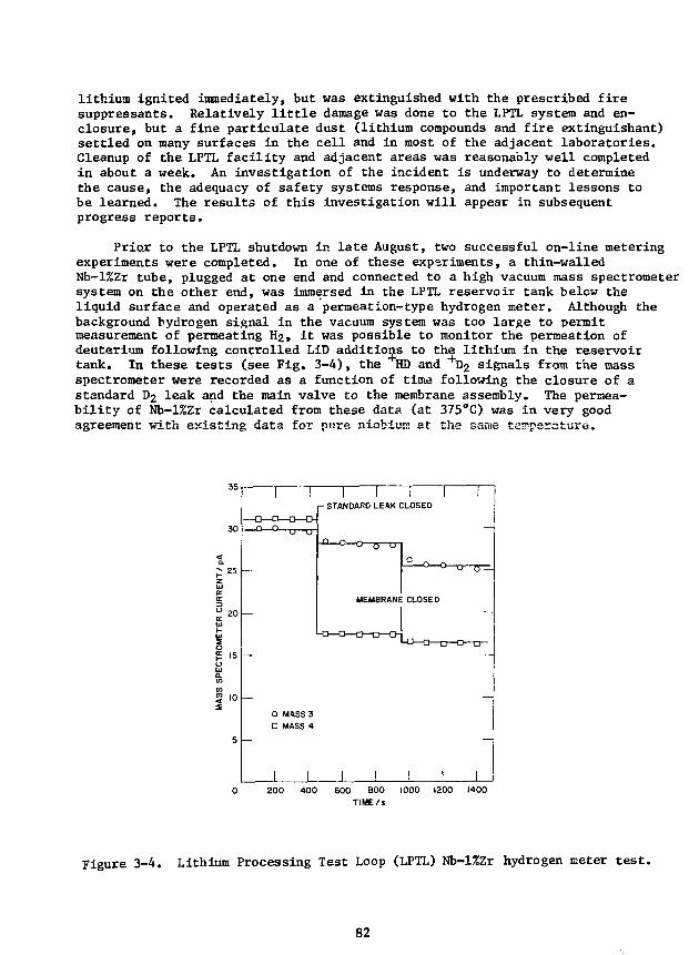
lithium ignited immediately, but was extinguished with the prescribed firesuppressants. Relatively little damage was done to the LPTL system and en-closure, but a fine particulate dust (lithium compounds and fire extinguishant)settled on many surfaces in the cell and in most of the adjacent laboratories.Cleanup of the LPTL facility and adjacent areas was reasonably well completedin about a week. An investigation of the incident is underway to determinethe cause, the adequacy of safety systems response, and important lessons tobe learned. The results of this investigation will appear in subsequentprogress reports.
Prior to the LPTL shutdown in late August, two successful on-line meteringexperiments were completed. In one of these experiments, a thin-walledNb-l%Zr tube, plugged at one end and connected to a high vacuum mass spectrometersystem on the other end, was immersed in the LPTL reservoir tank below theliquid surface and operated as a permeation-type hydrogen meter. Although thebackground hydrogen signal in the vacuum system was too large to permitmeasurement of permeating H2, it was possible to monitor the permeation ofdeuterium following controlled LiD additions to the lithium in the reservoirtank. In these tests (see Fig. 3-4), the HD and +D 2 signals from the massspectrometer were recorded as a function of time following the closure of astandard D2 leak and the main valve to the membrane assembly. The permea-bility of Nb-l%Zr calculated from these data (at 375°C) was in very goodagreement with existing data for pure niobium at the same temperature.
20
10 —
1—1—1 1 rI - STANDARD LEAK CLOSED
MEMBRANE CLOSED
-a—a—cr
O MASS 30 MASS 4
I I J I200 400 600 BOO 1000 1200 1400
TIME/s
Figure 3-4. Lithium Processing Test Loop (LPTL) Nb-l%Zr hydrogen meter t e s t .
82
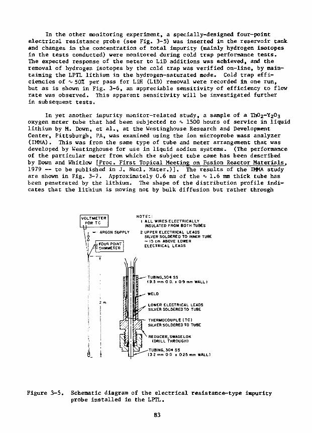
In the other monitoring experiment, a specially-designed four-pointelectrical resistance probe (see Fig. 3-5) was inserted in the reservoir tankand changes in the concentration of total impurity (mainly hydrogen isotopesin the tests conducted) were monitored during cold trap performance tests.The expected response of the meter to LiD additions was achieved, and theremoval of hydrogen isotopes by the cold trap was verified on-line, by main-taining the LPTL lithium in the hydrogen-saturated mode. Cold trap effi-ciencies of -v 50% per pass for LiH (LiD) removal were recorded in one run,but as is shown in Fig. 3-6, an appreciable sensitivity of efficiency to flowrate was observed. This apparent sensitivity will be investigated furtherin subsequent tests.
In yet another impurity monitor-related study, a sample of aoxygen meter tube that had been subjected to t 1500 hours of service in liquidlithium by M. Down, et al., at the Westinghouse Research and DevelopmentCenter, Pittsburgh, PA, was examined using the ion microprobe mass analyzer(IMMA). This was from the same type of tube and meter arrangement that wasdeveloped by Westinghouse for use in liquid sodium systems. (The performanceof the particular meter from which the subject tube came has been describedby Down and Whitlow [Proc. First Topical Meeting on Fusion Reactor Materials,1979 — to be published in J. Nucl. Mater.)]. The results of the DMA studyare shown in Fig. 3-7. Approximately 0.6 mm of the •v 1.6 mm thick tube hasbeen penetrated by the lithium. The shape of the distribution profile indi-cates that the lithium is moving not by bulk diffusion but rather through
NOTES:1 ALL WIRES ELECTRICALLY
INSULATED FROM BOTH TUBES
2 UPPER ELECTRICAL LEADSSILVER SOLDERED TO INNER TUBE~ IS cm ABOVE LOWERELECTRICAL LEADS
TUBING.304 SS(9 .5 mm 0 D. x 0 9 i
WELD
LOWER ELECTRICAL LEADSSILVER SOLDERED TO TUBE
THERMOCOUPLE tTC)SILVER SOLDERED TO TUBE
REDUCER,SWAGELOK(DRILL THROUGH)
TUBING, J04 SS(3 2 mm 0 D i 0 25 mm WALL)
Figure 3-5. Schematic diagram of the electrical resistance-type impurityprobe installed in the LPTL.
83
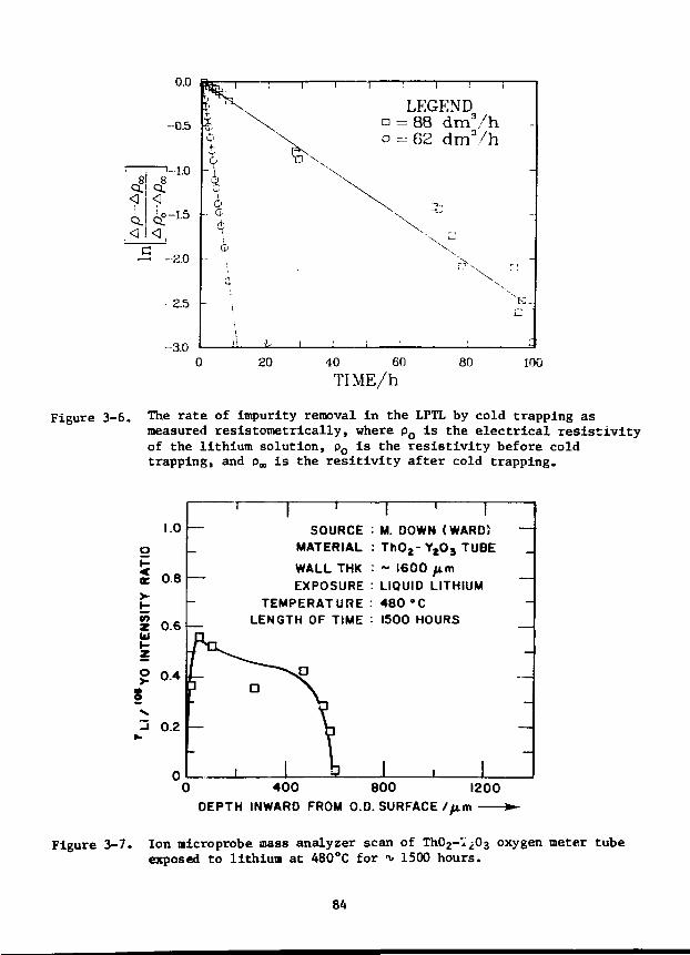
0.0
-0.5
-2.5
-3.0
1 x0V
0- 0
1
iii
\T J V
I
no
\
1 1 i
LEGEND= 88 dm3
- 6 2 dm3
i
/h -/h
-
-
20 40 60
TIME/h80 100
Figure 3-6. The rate of impurity removal in the LPTL by cold trapping asmeasured resistometrically, where pQ is the electrical resistivityof the lithium solution, po is the resistivity before coldtrapping, and pm is the resitivity after cold trapping.
1.0
0.8
I 'SOURCE
MATERIAL
WALL THKEXPOSURE
TEMPERATURELENGTH OF TIME
\ ' IM. DOWN (WARD)ThO2-Y2O3 TUBE~ 1600 fimLIQUID LITHIUM480 °C1500 HOURS
10 400 800 1200
DEPTH INWARD FROM O.D. SURFACE /fj.m
Figure 3-7. Ion microprobe mass analyzer scan of Th02-i203 oxygen meter tubeexposed to lithium at A80°C for ^ 1500 hours.
84

interconnected pores at a rate of "\> 3.5 mm/year. M *;his rate, the lifetimeof a given tube, before electrolyte shorting occurred, would be somethingless than 6 months. The results of this examination of the lithium-exposedTI1O2-Y2O3 tube point out one of the major difficulties in using ceramic-typematerials in a lithium environment. Any ceramic materials developed for :;sein electrolytic lithium metering systems would, in addition to being inertto lithium, have to have a very high density (near 100%) with no interconnectedporosity.
3.2.1.2 Alternative Breeder Material Studies
R. G. Clemmer, P. A. Finn, N. R. Chellew and V. A. Maroni, ChemicalEngineering Division
An experimental program has been initiated to evaluate various aspectsof the tritium recovery and impurity control questions facing tritium breedingmaterials that represent alternatives to liquid lithium. Prime candidatesin this regart are lithium-lead alloys (solid and liquid) and lithium-containingceramics. A number of experiments are either underway or in the planningstages. The scope and objectives of these experiments are summarized below:
• A Li7Pb2 loaded Zircaloy capsule has been fabricated and loadedinto the Oak Ridge Reactor (ORR) in the poolside position. Thepurposes of this experiment are to examine the tritium distributionprofile following irradiation to a dose sufficient to generate^ 30 Curies of tritium and to set up a postirradiation examinationprogram that can be used in subsequent in-pile tritium-breeder tests.
• An in-pile solid breeder experiment with capability for in-situtritium recovery and breeder temperature control, is currentlybeing planned. The purposes of this experiment are to determinetritium-holdup characteristics of solid breeder materials understeady-state recovery conditions, to examine breeder materialmorphology changes in a radiation environment, and to investigatebreeder/structure compatibility under irradiation.
• The applicability of the all-lithium-halide molten salt extractionmethod for recovering tritium and impurities from liquid lithiumis being tested on lead-rich lithium-lead alloys in the liquidstate. If cross contamination of the lead alloy (with halogen)and the salt (with lead) presents no problems, the method shouldbe even better suited to the lead-lithium alloys than it hasalready proven to be with liquid lithium.
The in-pile experiments described above are being carried out cooperativelywith R, L. Senn of Oak Ridge National Laboratory, E. R. Ebersole of EBR-II,Idaho, and A. G. Hins of the ANL Materials Science Division.
3.3 Engineering Test Facility Studies
P. A. Finn, R. G. Clemmer and V. A. Maroni, Chemical EngineeringDivision
The DOE design activities for a near-term tokamak power reactor havebeen consolidated in a single design center under the direction of D. Steiner
85

at the Oak Ridge National Laboratory. The reactor, the Engineering TestFacility (ETF) will be the next fusion device after TFTR currently beingbuilt at PPPL. The ANL contribution to this effort involves primary responsi-bility for the design of ETF fuel processing and tritium containment systems.During FY 1979, the work centered primarily on scoping studies and R&D assess-ments which are now complete. In FY 1980, a detailed design of the ETF tritiumsystems is being carried out, with updating as necessitated by changes in thebasic ETF reactor design. Specific tasks completed during the second of FY 1979are summarized below.
A three-dimensional neutronic calculation of experimental breeder-test-module size effects was conducted in collaboration with Y. Gohar of ANL/AP.The model used in the calculation was basad on inserting various-size test-modules into ETF at the out-boari horizontal mid-plane position. The remainderof the blanket was assumed to be non-breeding. The principal conclusions ofthis study are summarized in Table 3-3.
Table 3-3. Conclusions from the Study of Experimental Breeder/EnergyConversion Module Size Effects
Modules with front face dimensions in the range0.5 m x 0.5 m to 1.0 m x 1.0 m and with thicknessof 0.5 to 1.0 would be relatively free of boundaryeffects from a neutronic viewpoint.
Single module studies would yield meaningful breeder/energy conversion system test data.
Tests of blanket system integration and the produc-tion of meaningful quantities of sensible heat wouldrequire several test modules.
If module size becomes an issue, considerable usefulinformation could probably be gained from small, re-flector-shrouded test modules.
The maingfulness of breeder/energy conversion experi-ments on ETF is probably more sensitive to duty factorand repetitive pulsing characteristics than to modulesize considerations.
A computer subroutine was developed to simulate the processing step ofthe lithium-droplet-type divertor concept being considered for use en ETF.Lithium flow rates, mean processing residence times, and tritium removalefficiencies are adjustable in the program. The processing model is based
86
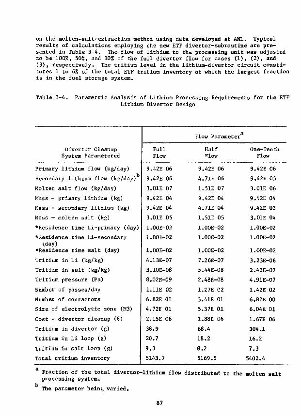
on the molten-salt-extraction method using data developed at ANL. Typicalresults of calculations employing che new ETF divertor-subroutine are pre-sented in Table 3-4. The flow of lithium to the processing unit was adjustedto be 100%, 50%, and 10% of the full divertor flow for cases (1), (2), and(3), respectively. The tritium level in the lithium-divertor circuit consti-tutes 1 to 6% of the total ETF tritium inventory of which the largest fractionis in the fuel storage system.
Table 3-4. Parametric Analysis of Lithium Processing Requirements for the ETFLithium Divertor Design
Divertor CleanupSystem Parametered
Primary lithium flow (kg/day)
Secondary lithium flow (kg/day)
Molten salt flow (kg/day)
Mass - primary lithium (kg)
Mass - secondary lithium (kg)
Mass - molten salt (kg)
*Residence time Li-primary (day)
*iiesidence time Li-secondary(day)
*Residence time salt (day)
Tritium in Li (kg/kg)
Tritium in salt (kg/kg)
Tritium pressure (Pa)
Number of passes/day
Number of contactors
Size of electrolytic zone (M3)
Cost - divertor cleanup ($)
Tritium in divertor (g)
Tritium in Li loop (g)
Tritium in salt loop (g)
Total tritium inventory
FullFlow
9.V2E 06
9.42E 06
3.01E 07
9.42E 04
9.42E 04
3.01E 05
1.00E-02
1.00E-02
1.00E-02
4.13E-07
3.10E-08
8.02E-09
1.11E 02
6.82E 01
4.72E 01
2.15E 06
38.9
20.7
9.3
5143.7
Flow Parameter
Half''low
9.42E 06
4.71E 06
1.51E 07
9.42E 04
4.71E 04
1.51E 05
1.C0E-02
1.00E-02
1.00E-02
7.26E-07
5.44E-08
2.48E-08
1.27E 02
3.41E 01
5.37E 01
1.88E 06
68.4
18.2
8.2
5169.5
One-TenthFlow
9.42E 06
9.42E 05
3.01E 06
9.42E 04
9.42E 03
3.01E 04
1.00E-02
1.00E-02
1.00E-02
3.23E-06
2.42E-07
4.91E-07
1.42E 02
6.82E 00
6.04E 01
1.67E 06
304.1
16.2
7.3
5402.4
Fraction of the total divertor-lithium flow distributed to the molten saltprocessing system.
The parameter being varied.
87

A preliminary fuel recycle and purification system layout has beenscoped out for ETF as shown in Fig. 3-8. A complete parameter list for theETF tritium and vacuum systems has been computed (using TCODE) and transmittedto the ETF Design Center. A fractional burnup of -\< 102 is achieved with aparticle confinement time of 1 s and a reflection coefficient of 0.85. Thetotal tritium inventory is 5.5 kg, most of which ( 4.8 kg) is in storage.The total tritium inventory could be reduced considerably by relaxing thestorage requiremente.
REACTOR BUILDING TRITIUM FACILITY BUILDING
1 PLASMA CHAMBER2 DIVERTOR3 DEBRIS SEPARATOR
4, 8 DT CRYOCONDENSATION PUMPS5 HELIUM PUMP6 SURGE TANK7 NEUTRAL BEAM INJECTOR9 TRITIUM RECOVERY, DIVERTOR
10,11.12 REGENERATION PUMPS13,11 METAL BELLOWS PUMPS
15 FUEL CLEANUP UNIT16 ISOTOPIC SEPARATION UNIT17 TRITIATED WASTE TREATMENT18 EMERGENCY AIR DETRITIATION SYSTEM19 TERTIARY ENCLOSURE20 WATER - TRiTIUM RECOVERY UNIT21 SECONDARY ENCLOSURE22 DETRITIATED GASES: N*. Oj, CO223 HELIUM (TRITIUM -FREEl24 TRITIUM WASTES25 T2-SHIPMENT/RECEIVING26 T, AND DT STORAGE27 0 2 SUPPLY28 Oj STORAGE29 FUEL BLENDER30 PELLET FUELER3 I D j - GAS FUELER32 D a - COVER GAS VACUUM SYSTEM33 EVACUATED BUILDING VACUUM SYSTEM
Figure 3-8. Fuel cycle scenario for ETF.
88

-TURBOMOLECULAR PUMP
L-LESS PUMP
OIL-LESS PUMPOXIDIZER
EMERGENCY AIR- DETRIATION
SYSTEM
ABSORBER
»—j> VENT
T TRITIATED1—WASTE
TREATMENT
Figure 3-9. Processing system for evacuated building.
Table 3-5. Comparative Assessment of Vacuum Versus Inert AtmosphereBuilding: Tritium Containment Implications
Considerations Vacuum BuildingInert/Artient
Building
Building structural failureTime average residual
tritium level
HTO formation (moistureassistedj
HTO soaking/desoaking(surfaces)
Post-accic^nt release cleanup
Post-shutdown access
Scrubber system size/costimpact
Ex-building space impact
Overall tritium-related costimpact
Design-connected R&D require-ments
Overall impact on designdecision
*(?)
Toss Up- _ - _
0,+
Favored approach.
Some problems tnat appear resolvable.
Some critical problems chat need resolution.
Seems not to be a high-level design choice drive.
89
An analysis was made of the limits of anticipated tritium leakage ratesfrom the plasma chamber to the reactor building for ETF. The ETF buildingand vacuum parameters upon which the analysis was based were supplied by theGeneral Atomic Company; a major co-participant in ETF. An optimistic analysisemploying simple steady-state leakage and flushing considerations resulted inan allowable leak rate of < 4 x 10"^ Pa-m3/s of DT to avoid exceeding themaximum permissible tritium (as HTO) concentration (MPC) in a controlledarea, 5 uCi/m3. A more pessimistic but perhaps more realistic analysiswhich included adsorption of HTO (formed from leaked DT) on building surfacesand its subsequent release, indicated that for any reasonably achievable leakrate, a normal-operating building base pressure of 10~6 Pa would be necessaryto assure that the up-to-air level would not exceed the MPC. The conclusionsdrawn from this analysis are (1) that bubble suits may have to be specifiedfor routine maintenance, (2) that the plasma chamber can tolerate a pressureof 1.33 E-2 Pa in the reactor building if the leakage rate associated withthis is sl.33 E-3 Pa»m3/s, and (3) that the allowable out leakage of DTfrom the torus to the reactor building is probably considerably less than4 E-5 Pa»m3/s (3 E-4 torr«Jl/s).
An analysis of the impact of the ETF vacuum boundary location from thetritium containment viewpoint was done. Alternate scenarios to the fuelrecycle and purification system layout for ETF were developed to handle thedifferent boundary locations. The boundaries considered were (1) a vacuumbuilding containing either a welded torus or a mechanically-sealed torus,and (2) a sealed building with an inert atmosphere containing either a weldedtorus or a mechanically-sealed torus with a vacuum boundary at the TF coil.The major result was that any of the vacuum boundary locations could be handledfrom the tritium viewpoint with none having a clear decisive advantage.
The major impact of the use of a vacuum building would be the need fordeveloping oil-less, doubly contained high vacuum and fare pumping equipment,and large separative gate valves to facilitate removal of pump assemblies.In the event of an accident, the on-line scrubbing system employed duringnormal operation would be bypassed to eliminate large impedances. An exampleof the type of pumping system for this scenario is shown in Fig. 3-9. Inusing a building with an inert atmosphere, no change would be needed in thebasic ETF layout if the vacuum boundary was a welded torus; however, tritiumwould probably be released each time access into the welded torus was requiredfor maintenance. If the vacuum boundary were at the TF coil, the space betweenthe mechanical-seal and the boundary could be swept with a low pressure Djgas stream which would reduce T2 permeation into the boundary area. Theexhaust gas could be handled by a conventional cryocondensation pumping systemwhich would trap D2>DT,DT in a regenerable form. A comparative assessmentof the two cases is shown in Table 3-5.
The data base and requirements for ETF tritium handling technology havebeen reviewed. There are a number of features unique to ETF that will havea considerable impact upon tritium handling considerations. For the firsttime, a fusion reactor will have a complete, integrated fuel recycling systemin which substantial quantities (up to 10 kg/yr) of tritium will be consumed.The reactor will be surrounded by a large evacuated enclosure having aheterogeneity of surfaces which could contain substantial amounts of sorbedtritium. The divertor collector will use liquid lithium and will require tritium
90

recovery rates that are in excess of those for a full-scale commercial fusionreactor blanket. The first wall and blanket will be water-cooled (probablyD20) and there is the potential for excessive ingress of tritium into thecoolant. Components exposed to the plasma chamber will experience a signifi-cant flux of 14 MeV neutrons along with continuous tritium infiltration. Inorder to test the viability of various blanket concepts, full-scale blanketmodules will be tested. These features require significant advances in thestate of tritium technology.
References
1. C. D. Boley, "Fusion Power Program Quarterly Progress Report,"January-March, 1979, Argonne National Laboratory, ANL/FPP-79-2,(1979).
2. S. Tamor and A. Engebretson, Science Applications, Inc., LAPS-9,SAI-75-6101J (1975); S. Tamor, Science Applications, Inc., LAPS-21,SAI-76-773LJ (19 76).
3. B. A. Trubnikov, in Reviews of Plasma Physics, edited by M. A. Leontovich(Consultanta Bureau, N.Y., 1979), Vol. VII, p. 345.
4. C. C. Baker, et al,3 "The Impact of Alternate Fusion Fuels on FusionReactor Technology," Argonne National Laboratory, ANL/FPP/TM-128, (1979).
5. C D . Boley, Bull. Am. Phys. Soc. 24, 939 (1979).
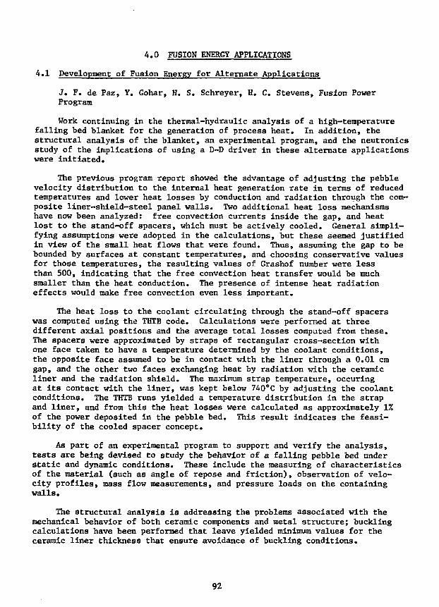
4.0 FUSION ENERGY APPLICATIONS
4.1 Development of Fusion Energy for Alternate Applications
J. F. de Paz, Y. Gohar, H. S. Schreyer, H. C. Stevens, Fusion PowerProgram
Work continuing in the thermal-hydraulic analysis of a high-temperaturefalling bed blanket for the generation of process heat. In addition, thestructural analysis of the blanket, an experimental program, and the neutronicsstudy of the implications of using a D-D driver in these alternate applicationswere initiated.
The previous program report showed the advantage of adjusting the pebblevelocity distribution to the internal heat generation rate in terms of reducedtemperatures and lower heat losses by conduction and radiation through the com-posite liner-shield-steel panel walls. Two additional heat loss mechanismshave now been analyzed: free convection currents inside the gap, and heatlost to the stand-off spacers, which must be actively cooled. General simpli-fying assumptions were adopted in the calculations, but these seemed justifiedin view of the small heat flows that were found. Thus, assuming the gap to bebounded by surfaces at constant temperatures, and choosing conservative valuesfor those temperatures, the resulting values of Grashof number were lessthan 500, indicating that the free convection heat transfer would be muchsmaller than the heat conduction. The presence of intense heat radiationeffects would make free convection even less important.
The heat loss to the coolant circulating through the stand-off spacerswas computed using the THTB code. Calculations were performed at threedifferent axial positions and the average total losses computed from these.The spacers were approximated by straps of rectangular cross-section withone face taken to have a temperature determined by the coolant conditions,the opposite face assumed to be in contact with the liner through a 0.01 cmgap, and the other two faces exchanging heat by radiation with the ceramicliner and the radiation shield. The maximum strap temperature, occuringat its contact with the liner, was kept below 740°C by adjusting the coolantconditions. The THTB runs yielded a temperature distribution in the strapand liner, and from this the heat losses were calculated as approximately 1%of the power deposited in the pebble bed. This result indicates the feasi-bility of the cooled spacer concept.
As part of an experimental program to support and verify the analysis,tests are being devised to study the behavior of a falling pebble bed understatic and dynamic conditions. These include the measuring of characteristicsof the material (such as angle of repose and friction), observation of velo-city profiles, mass flow measurements, and pressure loads on the containingwalls.
The structural analysis is addressing the problems associated with themechanical behavior of both ceramic components and metal structure; bucklingcalculations have been performed that leave yielded minimum values for theceramic liner thickness that ensure avoidance of buckling conditions.
92

The possibility of using a D-D driver is being considered; the calcula-tions show the advantage of this driver in terms of maximizing the amountof power released as high temperature heat and lessening the problems assoc-iated with the induced activity of the material. Also, a higher power densityis obtained with this driver; this is expected to result in more favorableconditions for removal of the heat with a falling bed blanket.
93

5.0 ENVIRONMENT AND SAFETY
5.1 Fusion Reactor Safety Studies
5.1.1 Studies of Air-Detritiation Operations
R- H. Land and V. A. Maroni, Chemical Engineering Division, andM. Minkoff, Applied Mathematics Division
Work on the modified version of TSOAK (supported during FY 1979 by acontract with EG&G, Idaho) is now essentially complete. During the secondhalf of 1979, the modified code (TSOAK-Ml) was run against previouslyobtained enclosure detritiation data with quite good results.1 Six out ofeight data sets gave convergence to a reasonable set of reaction/adsorption/release parameters (see Fig. 5-1). The relative differences in value foreach parameter from one data set to another are consistent with expectationsbased on differing experimental conditions. For example, referring toFig. 5-1, the enclosure tests run by flushing moist, tritium free, room airthrough the enclosure resulted in higher reaction rate parameters, but loweradsorption and release rate parameters than obtained for enclosure testsdone using a closed cycle detritiation unit based on conversion of moleculartritium to HTO followed by aolecular sieve drying. The higher average rela-tive humidity in the enclosure during the once through flushing tests isbelieved to account for the observed variations in parameter values whencompared to the closed cycle detritiation tests. The significance of thedifferences in the instrument correction factors is not clear at this time.
The principal conclusions and recommendations drawn from this study maybe summarized as follows: (1) The simplified reaction/adsorption/releasemodel-'- employed in TSOAK-Ml appears to be capable of predicting the observa-tions of experimental detritiation tests, but should be subjected to furtherexamination using results from large enclosures and, if possible, from actualfacility buildings. Only through extend utilization for a wide range of testconditions will it be possible to validate the credibility of the -model.(2) Pseudo-second-order reaction-rate parameters (for T2 + H2O £ HTO + HT)derived from previous small cubicle detritiation experiments conducted atANL are considerably greater (103 to 107 times) than comparable parametersderived from isostatic kinetics studies done in well-characterized glassbulbs. This is belir.ved to be related, more than anything else, to theheterogeneity of surface conditions in typical enclosures and the convectiveenvironments that result from recycling of the enclosure atmosphere. (3) Theprojected consequences of the effects incorporated in the TSOAK-Ml model,when extropolated to anticipated fusion reactor facilities, seem to be lessserious1 than was previously suggested, at least to the extent that para-meter values from the ANL cubicle experiments are close to being representa-tive of conditions in such facilities.
References
1. R. H. Land, V. A. Maroni and M. Miwkoff, "TSOAK-Ml: A Computer Code toDetermine Tritium Reaction/Adsorption/Release Parameters from Experi-mental Air Detritiation Tests," Argonne National Laboratory ReportANL-79-84 (1979).
94
O =O =
1Figure 5-1. TS0AK-M1 analysis of duplicate detritiation test data sets
obtained with the 0.050 in3 enclosure at ANL.
95
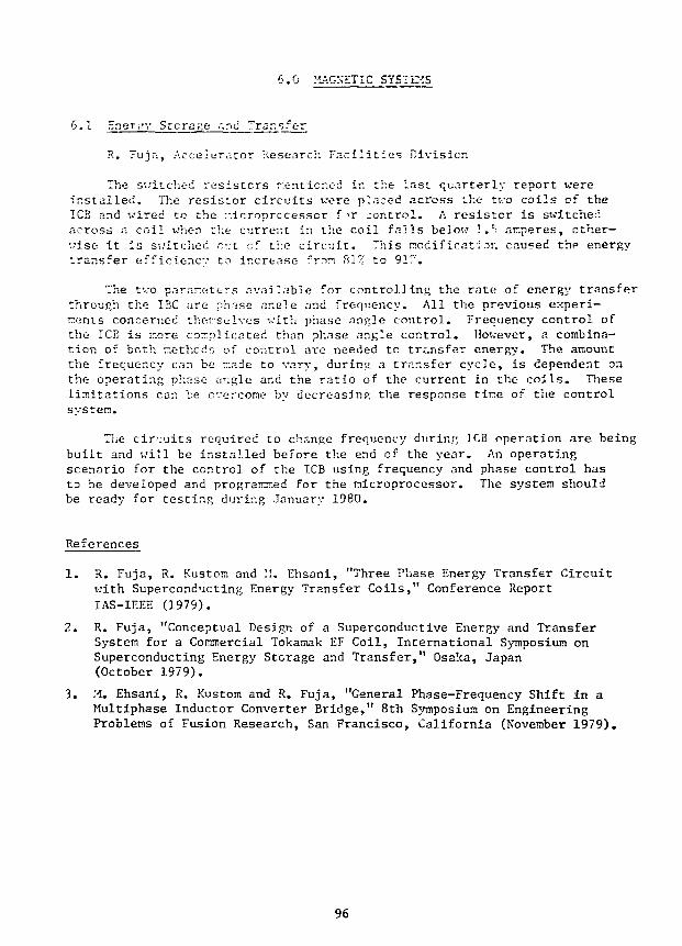
6.0 MAGNETIC SYSTEMS
6.1 Hner>;v Storage and :.rar.sfc-r
R. Fujr:, Accelerator Research Facilities Division
The switched resistors mentioned ir. the last quarterly report wereinstalled. The resistor circuits vere placed across the two coils of theTCB and wired to the microprocessor f T jontrol. A resistor is switchedacross a coil when the current in the coil falls below 3.5 amperes, other-wise it is switched out of the circuit. This nod ificati.3n caused the energytransfer efficiency to increase "mm 81'' to 91".
The two parameters available for controlling the rate of energy transferthrough the IBC are p'mse ancle and frequency. All the previous experi-ments concerned themselves with phase angle control. Frequency control ofthe TCB is more complicated than phase angle control. However, a combina-tion of both methcds of control are needed to transfer energy. The amountthe frequency can be made to vary, during a transfer cycle, is dependent onthe operating phase angle and the ratio of the current in the coils. Theselimitations can be overcome by decreasing the response tine of the controlsystem.
The circuits required to change frequency during ICB operation are beingbuilt and will be installed before the end of the year. An operatingscenario for the control of the ICB using frequency and phase control hasto be developed and programed for the nicroprocessor. The system shouldbe ready for testing during January 1980.
References
1. R. Fuja, R. Kustora and I!. Ehsani, "Three Phase Energy Transfer Circuitwith Superconducting Energy Transfer Coils," Conference ReportIAS-IEEE (1979).
2. R. Fuja, "Conceptual Design of a Superconductive Energy and TransferSystem for a Commercial Tokamak EF Coil, International Symposium onSuperconducting Energy Storage and Transfer," Osaka, Japan(October 1979).
3. M. Ehsani, R. Kustom and R. Fuja, "General Phase-Frequency Shift in aMultiphase Inductor Converter Bridge," 8th Symposium on EngineeringProblems of Fusion Research, San Francisco, California (November 1979).
96

7.C APPLIED PLASMA PHYSICS
7.1 Atomic Theory
7.1.1 The Betne Cross Sections for the Ionization of Li-Like Ions by ElectronImpact
K. Cheng and Y-K. Kim, Radiological and Environmental Research Division
The Bethe cross section for an excitation to a discrete state jn^ isgiven by
c = 4-a2R/I [A l"n(T/R) + B + C R/T], (1)n Q n n n
o
v.'here aQ = 0.529 A, R = 13.6 eV, 1 - incident electron energy, and A , B ,and C are Betht parameters derived from the properties of the target atom.We l i s t in Tablc 7-1 the values of the Bethe parameters for a few exciteds ta tes , calculated from tha Hartree-Fock wavefunctions. A sum rule existsfor the Bethe cross sections (including continuum transi t ions) :
r 2
0 = ) . ° = 47ranR/T [A J«(T/R) 4- E + C R/T] . (2)
a l l n
The sum of discrete excitations only,
c, = ) (discrete n only) a = 4Tra2R/T [A, ln(T/R) + B, + C, R/T]d ' ' n o " dd
(3)
can be calculated by summing the Bethe parameters in Eq. (1) for all discreteexcited states (including forbidden transitions). The difference betweeno and a is the ionization cnss section, 0.:
a. = 4TTa2R/T [A. ln(T/R) + 3 . + C. R/T] . (4)1 0 ! x x
The Mott exchange correction is given by
a = 4Tia2R2/T2 £ [ln(I./T) + i] N. , (5)x 0 ^ J J
where I. and N. are the ionization potential and occupation number, respec-tively,Jof the-'jth orbital. In Table .7-2, we list the Bethe parameters forot, od, o., and I..
97

Table 7-1. Bethe Parameters for Discrete Transitions of Li-Like Ions
Ion
AnB
Cn
AnBnn
( P +
AnBnCn
2s-2p
0.493
1.27
0.124
0.323
0.820
-0.105
0.228
0.574
-0.091
2s-3p
0.0684
-0.135
0.179
0.00540
-0.126
0.192
0.04 31
-0.114
0.201
2s-4p
0.0162
-0.0310
0.02".
0.0121
-0.0275
0.02JC
0.0093
-0.0239
0.0189
2s-?.s
0
0.0604
-0.103
0
0.0408
-0.105
0
0.0294
-0.107
2s-3d
0
0.158
-C.266
0
0.110
-0.273
0
0.0817
-0.278
Table 7-2. Bethe Parnmeters for Li-Like Ions
Ion A
0.701
0.J94
0.107
B
1.422
1.387
0.035
C
-5 .30
-0.369
-4 .93
i l s (Ry)
—
I2 s(Ry)
—
26.96 4.730
°t
0 .1
Q5+
°t
°d
0X
0.4760.401
0.075
0.345
0.290
0.055
—
0.8380.857
-0.019
0.541
0.572
-0.031
—
-5.30-0.349
-4.95
-5.30
-0.335
-4.97
—
3&.31
10.13
98

In Figs. 7-1 through 7-3, we compare our theoretical result with arecent experimental and theoretical data.3-5 xhe Fano plot (aT vs In T) usedin Figs. 7-1 through 7-3 emphasizes the high-energy region and is a powerfultool to elucidate asymptotic trends. It is clear from Fig. 7-3, for instance,that the last three experimental data do not show expected asymptotic shape.It is more difficult by our method to determine the heights of the curves thanthe slopes. Further theoretical vork is in progress tc obtain more reliableheights. The kinks in the experimental data signify the onset of the ioni-zation of K electrons.
The sum rule method has the advantage that the excitation and ionizationof K electrons are automatically included, whereas conventional theories,*'5require separate calculation for each possible mode of ionization. Our resultswere presented at an international conference.2
7.1.2 Transitions Between Low-Lying States of the First-Row Atoms
Compucer codes to calculate .all El, E2, and Ml transition probabilitiesamong L-sheM excited states (2sJ2p ) of isoelectronic sequences of the first-row atoms (Li through F) have been completed. Production runs will be madefor a large number of ions in the sequences as soon as sample results aretested against known experimental and theoretical data for reliability. Thiswill complete the first phase of our project, i.e., calculation of allspectroscopic data for simple electronic configurations. Simple adaptationswil1 also allow us to calculate spectra for the isoelectronic sequences ofthe second-row atoms (Ne through Cl) in the near future.
T(eV)Figure 7-1. Fano plot for the ionization of C 3 + by electron impact. T is
the incident energy and a is the cross section. Solid curverepresents the present work, the circles are the experimentaldata from Ref. 3, dotted and dot-dashed curves stand for theoreticalresults from Refs. 4 and 5, respectively.
99
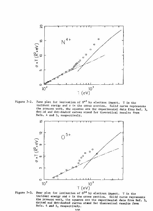
10"T(eV)
Figure 7-2. Fano plot for ionization of N 4 + by electron impact. T is theincident energy and o is the cross section. Solid curve representsthe present work, the squares are the experimental data from Ref. 3,dotted and dot-dashed curves stand for theoretical results fromRefs. 4 and 5, respectively.
10T(eV)
Figure 7-3. Fane plot for ionization of 0 5 + by electron impact. T is theincident energy and a is the cross section. Solid curve representsthe present work, the squares are the experimental data from Ref. 3,dotted and dot-dashed curves stand for theoretical results fromRefs. 4 and 5, respectively.
inn

References
1. Y.-K. Kim and M. Inokuti, Phys. Rev. A J3, 665 (1971).
2. Y.-K. Kim and K. T. Cheng, Abstracts of the /Ith International Conferenceon the Physics of Electronic and Atomic Collisions (Kyoto, Japan,August 28 - September 3, 1979), p. 218.
3. b. 11. Crandall, R. H. Phaneuf, 1!. E. Hasselquist, and D. C. Gregory,J. Phys. B JJ2, 1-249 (1979).
4. D. L. Moores, J. Phys. B LL, LI (1978).
5. L. B. Golden and I). H. Sampson, J. Phys. BIO, 2229 (1977).
101
FPP AND FPP-RELATED DOCUMENTS AUTHORED BY ARGONNE PERSONNEL
G. AYRAULT"Microscructure of Slngle-and Dual-Ion Irradiated V-15Cr-5Ti"
J. Met. Vol. 31 p. F49 (1979).
"Precipitation in Single-and Dual-Ion Irradiated Ti-6A1-4V"J. Met. Vol. 31 p. F60 (1979).
C. D. BOLEY, E. M. GEL BARD AND S. P. HIRSHMAN"Neoclassical Transport in Plasmas Containing Ions with MultipleCharge States"
Fhysicr, of Fluids 2^, 1280 (1979).
KOSTA BURBA"Cost Algorithms and Estimating Data,
Argonne National Laboratory, ANL/FPP/TM-123 (May, 1979).
K. T. CHENG & T.-K. KIM !
"Energy Levels, Wavelengths, and Transition Probabilities of Cu-LikeIons"
Atom. Data llual. Data Tables Z2, 1280 (19/9).
S. K. DAS, M. KAMINSKY, R. TISHLER AND J. C1XCHI"Surface Damage and Sputtering of ATJ Graphite as Candidate ArmorPlate Material for TFTR Under D+ Bombardment"
Accepted for publication in Jour, of Nuol. Mater. (1979).
G. FENSKE, S. K. DAS, M. KAMINSKY AND G. H. MILEY k
"The Effect of Dose on the Evolution of Cavities in 500-keV lie -IonIrradiated Nickel"
Accepted for publication in Jour, of llual. Mater. (1979).
L. R. GREENWOOD, R. R. HEIURICH, M. J. SALTMARSH AND C. B. FULMER"Integral Tests of Neutron Activation Cross Sections in a 9Be(d,n)Field at E, = 40 MeV"
Nuclear Soienee and Engineering, TL, 175 (1979).
D. M. GRUEN, S. VEPREK AND R. B. WRIGHT"Plasm-Materials Interactions and Impurity Control in Magnttically-Confined Thermonuclear Fi'sion Machines"
Topics in Current Chemistry 8_, (1979),
S. HARKNESS"Fusion Energy for Alternate Applications: Development of a HighTemperature Blanket for Synthetic Fuel Production"
Argonne National Laboratory, ANL/FPP/TM-117 (1979).
102

JUNGCHUNG JUHG"Theory and Use of the Radioactivity Code RACC" (code manual)
Argonne National Laboratory, ANL/FPP/TM-122 (May, 1979).
T.-K. KIM I K. T. CHENG"Beth Cross Sections for Ionization of C3 , Nu , and 05 "
Abstracts of :.Ith Int, Conf. on the Physics of Electronic& Atomic Collisions August 28-September 3, 1979, Kyoto, Japan,pp. 218-219.
M. A. KIRK AND L. R. GREENWOOD"Determination of the Fast Neutron Flux and Energy Spectrum in theLow-Temperature Fast-Neutron Facility in CP-5"
J. Hurt. Mat. SO, 159 (1979).
A. R. KRAUSS & D. M. GRUEN"Secondary Ion Emission from Clean and Oxygen-Covered BerylliumSurfaces-II: Energy Dependence"
Surface Soienae (in press).
A. R. KRAUSS AND R, B. WRIGHT"Energy and Mass Distributions of Sputtered Particles"
J. Hurt. Mat. (December 1979).
V. A. MARONI"Control of Tritium Permeation Through Fusion Reactor StructuralMaterials"
Proc. U.S. DOE Environmental Control Symposium, U.S. DOE ReportDOE/EV-0046 (1979) Vol. 2, pp. 39-52 (1979).
V. A. MARONI AND E. H. VAN UEVENTER"Materials Considerations in Tritium Handling Systems"
J. h'uol. Mater. 85_ & 86, 257 (1979).
F. V. NOLFI AND A. P. L. TURNER"Effects of Irradiation on Fusion Reactor Materials"
Damage Analysis and Fundamental Studies Quarterly ProgressReports. (January-March 1979 and Ap-il -June 19'73).U. S. DOE Report (1979).
F. V. NOLFI AND G. AYRAULT"Microstructural Evolution During Dual-Ion Irradiation of CandidateFusion Reactor Materials"
Presented at Intl. Conf. on Irradiation Behavior of MetallicMaterials for Fast Reactor Core Components. Ajaccio, Corsica, France,(June 5-7, 1979).
103
F. V. NOLFI, R. 0. SCATTERGOOD AND A. P. L. TURNER"Stress and Irradiation Induced Mass Transport"
Saripta Met. Vol. 13 pp. 231-236 (1979).
"Stress and Irradiation Induced Mass Transport"J. Met. Vol. 31 p. F-31 (1979).
F. V. NOLFI AND R. E. GOLD"Vanadium Alloys and Their Application to Fusion Reactor Development"
J. Met. Vol. 31 p. F-49 (1979).
LARRY TURNER"Safety of Fusion Magnets: Twelve Problem Areas,"
Argonne National Laboratory, ANL/FPP/TM-121 (April, 1979).
R. B. WRIGHT AND D. M. GRUEN"Discussion of the Origin of Secondary Photon and Secondary IonEmission During Energetic Particle Irradiation of Solids:I. The Collison Cascade"
J. Chem. Phye. (December 1979).
"Secondary Photon Emission Studies of Ion Bombardment Beryllium"Proc. VIII Int. Conf. Atomic Collisions in Solids, Hamilton,Ontario, (August 1970).
R. B. WRIGHT, M. J. PELLIN, D. M. GRUEN AND C. E. YOUNG"Laser Fluorescence Spectroscopy of Sputtered Uranium Atoms"
Ibid.
104