distribution system - university of misan · 2019-10-21 · connection schemes of distribution...
TRANSCRIPT

ANALS POWER SYSTEM ANALYSIS MISSAN UNIVERSITY\ COLLEGE OF ENGINEERING
Chapter Ten
Distribution System
The electrical energy produced at the generating station is conveyed tothe consumers through network of transmission line and distributionsystem.In general, the distribution system is the electrical system between thesub- station fed by the transmission system and the consumers meters. Itgenerally consists of feeders, distributors and the service main as showin the fig. below
-Feeders:-1A feeder is conductor Which connects the sub- station (or localizedgenerating station )To the area where power is To be distributed.Generally ,No tapping are taken from the Feeder so that the current in itremains the same throughout. The main consideration in the design of afeeder is the current carrying capacity.
ANALS POWER SYSTEM ANALYSIS MISSAN UNIVERSITY\ COLLEGE OF ENGINEERING
-utor :Distrib-2A distributor is a conductor from which tapping are taken for supply tothe consumers. In the fig .above AB, BC, CD and DA are thedistributor. The current through a distributor is not constant becausetapping are taken at various along its length.
-Servic Mains :-3A service mains is generally a small cable which connects thedistributor to the consumers terminals
A.C. DistributionNow-a-days electrical energy is generated, transmitted and distributedin the form of alternating current .One important reason for thewidespread use of alternating current in preference to directcurrent is the fact that alternating voltage can be conveniently changedin magnitude by means of a transformer. Transformer has made itpossible to transmit a.c. power at high voltage and utilize it at a safepotential. High transmission and distribution voltages have greatlyreduced the current in the conductors and the resulting line losses.There is no definite line between transmission and distributionaccording to voltage or bulk capacity. However, in general, the a.c.distribution system is the electrical system between the step-downsubstation fed by the transmission system and the consumers’ meters.The a.c. distribution system is classified into (i) primary distributionsystem and (ii) secondary distribution system.(i) Primary distribution system. It is that part of a.c. distribution systemwhich operates at voltages somewhat higher than general utilization andhandles large blocks of electrical energy than the average low-voltageconsumer uses. The voltage used for primary distribution depends uponthe amount of power to be conveyed and the distance of the substationrequired to be fed. The most commonly used primary distributionvoltages are 11 kV, 6·6 kV and 3·3 kV. Due to economicconsiderations, primary distribution is carried out by 3-phase, 3-wiresystem.

ANALS POWER SYSTEM ANALYSIS MISSAN UNIVERSITY\ COLLEGE OF ENGINEERING

ANALS POWER SYSTEM ANALYSIS MISSAN UNIVERSITY\ COLLEGE OF ENGINEERING
Connection schemes of distribution systemAll distribution of electrical energy is done by constant voltage system.In practice, the following distribution circuits are generally used :-
Radial System-1In this system, separate feeders radiate from a single substation and feedthe distribution at one end only. Fig.(10.4 ( ) shows a single linediagram of a radial system for d.c distribution where a feeder OCsupplies a distributor AB at point A . obviously, the distributor is fed atone end only i.e point A in this case.Fig. ( shows a single line diagram of radial system for a.cdistribution. The radial system is employed only when power isgenerated at low voltage and the substation is located at the center of theload.
This is the simplest distribution circuit and has the lowest initial cost.However, it suffers from the following draw back1- The end of the distributor nearest to the feeding point will be heavilyloaded .2-The consumers are dependent on a single feeder and singledistributor. Therefore, any fault on the feeder or distributor cost offsupply to the consumers who are on the side of the fault away from thesubstation.3-The consumer at the distant end of the distributor would be subjectedto serious voltage fluctuation when the load on the distributor changes.

ANALS POWER SYSTEM ANALYSIS MISSAN UNIVERSITY\ COLLEGE OF ENGINEERING
-Ring main system :-2In this system, the primaries of distribution transformers from a loop.The loop circuit starts from the substation bus-bars, makes a loopthrough the area to be served and returns to the substation. Fig. (10.5)shows the single line diagram of ring main system for a.c distribution.Where substation supplies to the closed feeder LMNOPQRS.
The distributors are tapped from different points M, O and Q of thefeeder through distribution transformers.The ring main system has the following a advantage .
1-There are less voltage fluctuations at consumers terminals.2- The system is very reliable as each distributor is fed via two feeders(Thus the distributor from point M is supplied by the feeders SLM andSRQPONM)In the event of fault on any section of the feeder, the continuity ofsupply is maintained. For example, suppose that the fault occurs at any point F of sectionSLM of the feeder. Then section SLM of the feeder can be isolated forrepairs and at the same time continuity of supply is maintained to all theconsumers via the feeder SRQPONM .

ANALS POWER SYSTEM ANALYSIS MISSAN UNIVERSITY\ COLLEGE OF ENGINEERING
-em :Inter connected syst-3When the feeder ring is energized by two or more than two generatingstations or substations, it is called inter- connected system.Fig. (10.6) shows the single line diagram of inter connected systemwhere the closed feeder ring ABCD is supplied by two substation S, andS2 at point D and C respectively .Distributors are connected to point O,P,Q and R of the feeder ringthrough distribution trans formers.
The inter connected system has the following a advantage.1-It increases the service reliability2-Any area fed from one generating station during peak load hours canbe fed from the other generating station. This reduces reserve powercapacity and increase efficiency of the system .
ANALS POWER SYSTEM ANALYSIS MISSAN UNIVERSITY\ COLLEGE OF ENGINEERING
*Requirement of Distribution SystemA considerable amount of effort is necessary to maintain an electricpower supply within the requirements of various type of consumers.Some of requirements of a good distribution system are :-
1-Proper voltage :.One important requirement of a distribution system is that voltagevariations at consumer's terminals should be as low as possible. Thechanges in voltage are generally caused due to the variation of load onthe system. Low voltage causes loss of revenue, inefficient lighting andpossible burning out of motors.High voltage cause lamps to be burn out permanently and may causefailure of other application .
Therefore, a good distribution system should ensure. That the voltagevariation at consumers terminates are within permissible limits. Thestatutory limit of voltage variations is of the rated value of theconsumer's terminals . Thus, if the declared voltage is 230 VThen the highest voltage of the consumers should not exceed 244 Vwhile the lowest voltage of the consumer should not be less than 216 V .
2-Availability of power on demand .Power must be available to the consumers in any amount that they mayrequire from time to line for example , motors may be started or shutdown, lights may be turned on or off, without advance warning to theelectric supply company . As electrical energy cannot be stored,therefore, the distribution system must be capable of supplying loaddemands of consumers. This necessitates that operating staff mustcontinuously study load patterns to predict in advance those major loadchanges that follow the known schedules .

ANALS POWER SYSTEM ANALYSIS MISSAN UNIVERSITY\ COLLEGE OF ENGINEERING
3-ReliabilityModern industry is almost dependent on electric power for its operation. homes and office building are lighted, heated, cooled and ventilated byelectric power. This calls for reliable service.Un fortunately, electric power, like everything else that man- made, cannever be absolutely reliable.However, the reliability can be improved to a considerable extent bya-Inter connected systemb-Reliable automatic control systemc-Providing additional reserve facilities.
*Design consideration in Distribution SystemGood voltage regulation of a distribution network is probably the mostimportant factors responsible for delivering good service to theconsumers.For this purpose, design of feeders and distributions requires carefulconsideration.
1-Feeders :-A feeder is designed from the point of view of its current carryingcapacity which the voltage drop consideration is relatively unimportant.It is because voltage drop in a feeder can be compensated by means ofvoltage regulation equipment at the station .
2-Distributors :-A distributor is designed from the point of view of the voltage drop in it.It is because a distributor supplies power to the consumers and there isa statutory limit of voltage variation at the consumers terminal( . The size and length of the distribution shouldbe such that the voltage at the consumer's terminates is within thepermissible limits.

ANALS POWER SYSTEM ANALYSIS MISSAN UNIVERSITY\ COLLEGE OF ENGINEERING
Ex1) A 2 wire d.c distributor cable AB is 2km long and supplies loadsof 100 A, 150 A , 200 A and 50 A situated 500 m , 1000 m , 1600 m and2000 m from the feeding point A . Each conductor has Resistance of0.01 Ω per 1000 m calculate the potential difference at each load pointif the potential difference at point A is 300 volt .
So1)
Resistance per 1000 m of distributorResistance of section AC, RAC
Resistance of section CD, RCD
Resistance of section DE, RDE
Resistance of section EB, REB
Potential difference P.D at load point C
A 500A C 400A D 250A E 50AB
50A200A150A100A
500 m 500 m 600 m 400 m

ANALS POWER SYSTEM ANALYSIS MISSAN UNIVERSITY\ COLLEGE OF ENGINEERING
Ex2) An electric train runs between two sub- station 6 km apartmaintained at voltage 600 V and 590 V , respectively and draws aconstant current of 300 A while in motion. The track resistance of goand return path is 0.04 Ω/km . calculate1-The point along the track where minimum potential occurs.2-The current supplied by the two sub- stations where the train is at thepoint of minimum potential.
So1) Suppose that minimum potential occurs at point M, at distance X kmfrom the substation A . as in the fig. below
Resistance of track (go Return path) per km = 0.04 Ω
A IA M 300-IA B
X
600 V 300 A 590V

ANALS POWER SYSTEM ANALYSIS MISSAN UNIVERSITY\ COLLEGE OF ENGINEERING
from equations (1) and (2) we get
Substituting the value of in eq.(1). We get
*For to be minimum, its differential coefficient write Xmust be zero :-
minimum potential occurs at a distanceOf 3.425 km from the sub- station A.
*Current supplied by sub- station A
Current supplied by sub-station B

ANALS POWER SYSTEM ANALYSIS MISSAN UNIVERSITY\ COLLEGE OF ENGINEERING
Ex3) A single phase ring distributor ABCD A is fed at A. The loads at Band C are 20A at 0.8 p.f lag . and 15 A at 0.6 p.f lagging respectively,both expressed with reference to the voltage at A . The total impedanceof the three section AB, BC, and AC are(1+J1), (1+J2) and (1+J3) ohms respectively. Find the total current fedat A and the current in each section use thevenin's theorem to obtainthe result
So1)
Obviously, point B is at higher potential than point C the p.d (potentialdifference )between point B and C is thevenin's equivalent
Thevenins equivalent impedance can be found by looking into thenetwork from points B and C
1+J 31+J 1
CB
1+J 2
15 A0.6 Lag
20 A0.8 Lag
A
1+J 31+J 1
BC
20 A0.8 Lag
15 A0.6 Lag

ANALS POWER SYSTEM ANALYSIS MISSAN UNIVERSITY\ COLLEGE OF ENGINEERING
Current fed at A
OR
A
B C
3
20 A0.8 lag= (16-J 12)
15 A0.6 lag
= (9-J 12)
ANALS POWER SYSTEM ANALYSIS MISSAN UNIVERSITY\ COLLEGE OF ENGINEERING
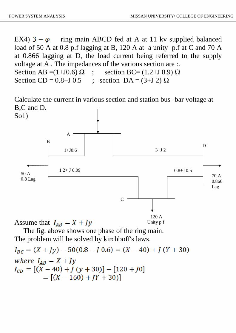
EX4) ring main ABCD fed at A at 11 kv supplied balancedload of 50 A at 0.8 p.f lagging at B, 120 A at a unity p.f at C and 70 Aat 0.866 lagging at D, the load current being referred to the supplyvoltage at A . The impedances of the various section are :.Section AB =(1+J0.6) Ω ; section BC= (1.2+J 0.9) ΩSection CD = 0.8+J 0.5 ; section DA = (3+J 2) Ω
Calculate the current in various section and station bus- bar voltage atB,C and D.So1)
Assume that The fig. above shows one phase of the ring main.The problem will be solved by kircbboff's laws.
AB
1+J0.6
50 A0.8 Lag
1.2+ J 0.09
C
3+J 2D
70 A0.866Lag
0.8+J 0.5
120 AUnity p.f

ANALS POWER SYSTEM ANALYSIS MISSAN UNIVERSITY\ COLLEGE OF ENGINEERING
Applying Kirchhoff's voltage law to mesh ABCD ; where
OR As the real or (active) and imaginary ( or reactive)Parts have to be separately zero.
And solving for X and y

ANALS POWER SYSTEM ANALYSIS MISSAN UNIVERSITY\ COLLEGE OF ENGINEERING