dk fr - prelectronics.com series/5335/manual... · inmetro br ocp-0029 programmable displays with a...
TRANSCRIPT

INMETROBR
OCP-0029
Programmable displays with a wide selection of inputs and outputs for display of temperature, volume and weight, etc. Feature linearisation, scaling, and difference measurement functions for programming via PReset software.
Interfaces for analogue and digital signals as well as HART® signals between sensors / I/P converters /frequency signals and control systems in Ex zone 0, 1 & 2 and for some modules in zone 20, 21 & 22.
Galvanic isolators for analogue and digital signals as well as HART® signals. A wide product range with both loop-powered and universal isolators featuring linearisation, inversion, and scaling of output signals.
PC or front programmable modules with universal options for input, output and supply. This range offers a number of advanced features such as process calibration, linearisation and auto-diagnostics.
A wide selection of transmitters for DIN form B mounting and DIN rail modules with analogue and digital bus communication ranging from application-specific to universal transmitters.
Displays
Temperature
Isolation
Ex interfaces
Universal
S I G N A L S T H E B E S T
5 3 3 5
2 - W i r e T r a n s m i t t e rw i t h H A R T ® P r o t o c o l
N o . 5 3 3 5 V 1 1 2 - I N ( 1 0 0 7 )F r o m s e r . n o . 0 9 0 9 2 7 0 0 0
DK
UK
FR
DE
Side 1
Page 15
Page 29
Seite 43

1
EF-overensstemmelseserklæring........................................ . 2Anvendelse.......................................................................... . 3Teknisk.karakteristik............................................................ . 3Montage./.installation.......................................................... . 3Applikationer....................................................................... . 4Bestillingsskema:.5335....................................................... . 5Elektriske.specifikationer.................................................... . 5Tilslutninger......................................................................... . 9Blokdiagram........................................................................ . 10Programmering.................................................................... . 11Forbindelse.af.transmittere.i.multidrop............................... . 13Mekaniske.specifikationer................................................... . 13Montering.af.følerledninger................................................. . 13Appendix............................................................................. . 57ATEX.Installation.Drawings.-.5335A,.UK,.FR,.DE,.DK........ . 58ATEX.Installation.Drawings.-.5335D,.UK,.FR,.DE,.DK........ . 62FM.Installation.Drawing.No..5300Q502.............................. . 70CSA.Installation.Drawing.No..533XQC03........................... . 72INMETRO.Instruções.de.Segurança................................... . 74
2-TRÅDS TRANSMITTER MED HART® PROTOKOL
PRetop 5335
Indholdsfortegnelse

2 3
2-TRÅDS TRANSMITTER MED HART® PROTOKOL
PRetop 5335
• Indgang for RTD, TC, Ohm eller mV • Ekstrem målenøjagtighed • HART®-kommunikation• Galvanisk isolation • Kan monteres i DIN form B følerhoved
Anvendelse
•. Temperaturlineariseret.måling.med.Pt100...Pt1000,.Ni100...Ni1000.eller.termo.elementføler.
•. Differens-.eller.gennemsnitstemperaturmåling.på.2.modstands-.eller.TC-følere.
•. Omsætning.af.lineær.modstandsændring.til.standard.analogt.strømsignal,.f.eks..fra.ventiler.eller.ohmske.niveaustave.
•. Forstærkning.af.bipolært.mV-signal.til.et.standard.4...20.mA.strømsignal.
•. Kobling.af.op.til.15.transmittere.til.et.digitalt.2-leder.signal.med.HART®-kommunikation.
Teknisk karakteristik
•. PR5335.kan.af.brugeren.i.løbet.af.få.sekunder.programmeres.til.at.måle.inden.for.alle.normerede.temperaturområder..
•. RTD-.og.modstandsindgangen.har.kabelkompensering.for.2-,.3-.og.4-leder.tilslutning.
•. 5335.er.konstrueret.med.et.højt.sikkerhedsniveau,.så.den.er.anvendelig.i.SIL.2.installationer.
•. Der.er.løbende.sikkerhedscheck.af.gemte.data.
•. Følerfejlsdetektering.iht..retningslinierne.i.NAMUR.NE.89.
Montage / installation
•. Kan.monteres.i.DIN.form.B.følerhoved..I.ikke-eksplosionsfarlige.områder.kan.5335.monteres.på.en.DIN-skinne.med.PR-beslag.type.8421.
•.NB:.Som.Ex-barriere.for.5335D.anbefaler.vi.5106B.
EF-OvERENSSTEMMELSESERKLæRINgSom.producent.erklærer
PR electronics A/S Lerbakken 10 DK-8410 Rønde
hermed.at.følgende.produkt:Type: 5335 Navn: 2-Tråds transmitter med HART® protokol
er.i.overensstemmelse.med.følgende.direktiver.og.standarder:
EMC-direktivet.2004/108/EF.og.senere.tilføjelserEN 61326-1 : 2006
For.specifikation.af.det.acceptable.EMC-niveau.henvises.til.modulets.elektriske.specifikationer.
ATEX-direktivet.94/9/EF.og.senere.tilføjelserEN 60079-0 : 2006, EN 60079-11 : 2007, EN 60079-15 : 2005 og EN 60079-26 : 2007 EN 61241-0 : 2006 og EN 61241-11 : 2006 ATEX-certifikat: KEMA 03ATEX1508 X (5335A)ATEX-certifikat: KEMA 03ATEX1537 (5335D)
Bemyndiget.organ.KEMA Quality B.v. (0344) Utrechtseweg 310, 6812 AR Arnhem P.O. Box 5185, 6802 ED Arnhem The Netherlands
Rønde,.18..december.2009. Kim.Rasmussen.. Producentens.underskrift

4 5
Elektriske specifikationerSpecifikationsområde:-40°C.til.+85°CFælles specifikationer:Forsyningsspænding,.DC.. Standard................................................... 8,0...35.V. CSA,.FM.&.ATEX....................................... 8,0...30.VIsolationsspænding,.test./.drift..................... 1,5.kVAC./.50.VACOpvarmningstid............................................. 30.sKommunikationsinterface..............................HART®.og.Loop.LinkSignal-./.støjforhold.......................................Min..60.dB.Reaktionstid.(programmerbar)...................... 1...60.sEEprom.fejlcheck..........................................<.10.sSignaldynamik,.indgang................................ 22.bitSignaldynamik,.udgang................................. 16.bitKalibreringstemperatur.................................. 20...28°C.Nøjagtighed,.størst.af.generelle.og.basisværdier:
+
-
+
-
V +
m A
V +
m A
+
-
+
-
V +
m A
+
-
+
-
V +
m A
V +
m A
+
-
+
-
+
-
+
-
+ -
+ -
+ -
+ -
+ -
+ -
2
1
2
2
1
1
RTD til 4...20 mA
TC til 4...20 mA
Modstand til 4...20 mA
Differens eller middel RTD, TC eller mV
2-trådsinstallation i kontrolrum
2-trådsinstallation i kontrolrum
2-trådsinstallation i kontrolrum
2-trådsinstallation i kontrolrum
mV til 4...20 mA 2-trådsinstallation
i kontrolrum
Bestillingsskema: 5335
Type version
5335 Standard. :.A.CSA,.FM.&.ATEX. :.D.
APPLIKATIONER
generelle værdier
.Indgangstype
Absolut.nøjagtighed
Temperatur-.koefficient
Alle ≤.±0,05%.af.span ≤.±0,005%.af.span./.°C.

6 7
Følerfejlsdetektering...................................... jaKortslutningsdetektering...............................Hvis.0%.>.30.ΩTC-indgang:
Koldt.loddestedskomp..(CjC).......................<.±1,0.°CEkstern.CjC.med.Ni100.eller.Pt100............. -40.≤.Tomg..≤.135°CFølerfejlsdetektering...................................... jaFølerfejlsstrøm:.. under.detektering...................................Nom..33.μA. ellers....................................................... 0.μAKortslutningsdetektering...............................Hvis.0%.>.5.mVSpændingsindgang:Måleområde.................................................. -800...+800.mVMin..måleområde.(span)................................ 2,5.mVIndgangsmodstand....................................... 10.MΩStrømudgang:Signalområde................................................ 4...20.mA.Min..signalområde......................................... 16.mAOpdateringstid............................................... 440.ms. . (660.ms.for.diff.)Fast.udgangssignal.......................................Mellem.4.og.20.mAUdgangssignal.ved.EEpromfejl.....................≤ 3,5.mABelastningsmodstand....................................≤ (Vforsyn..-.8)./.0,023.[Ω]Belastningsstabilitet......................................<.±0,01%.af.span./.100.ΩFølerfejlsdetektering:Programmerbar............................................. 3,5...23.mANAMUR.NE43.Upscale................................. 23.mANAMUR.NE43.Downscale............................. 3,5.mAAf span =.Af.det.aktuelt.valgte.område
Virkning.af.forsyningsspændings-.ændring.........................................................<.0,005%.af.span./.VDCVibration........................................................ IEC.60068-2-6.Test.FCLloyd’s.specifikation.nr..1.............................. 4.g./.2...100.HzMax..ledningskvadrat.................................... 1.x.1,5.mm2..flerkoret.ledningLuftfugtighed.................................................<.95%.RH.(ikke.kond.)Mål.................................................................Ø.44.x.20,2.mmKapslingsklasse.(hus./.klemme).................... IP68./.IP00Vægt.............................................................. 50.gElektriske specifikationer indgang:Max..nulpunktsforskydning.(offset)............... 50%.af.valgt.numerisk.max..værdiRTD- og lineær modstandsindgang:
Kabelmodstand.pr..leder.(max.).................... 5.ΩFølerstrøm.....................................................Nom..0,2.mAVirkning.af.følerkabelmodstand..(3-./.4-leder)..................................................<.0,002.Ω/Ω
Basisværdier
.Indgangstype
Basis-.nøjagtighed
Temperatur-.koefficient
Pt100.og.Pt1000 ≤.±0,1°C ≤.±0,005°C/°C
Ni100 ≤.±0,2°C ≤.±0,005°C/°C
Lin..R ≤.±0,1.Ω ≤.±5.mW./.°C
Volt ≤.±10.µV ≤.±0,5.µV./.°C
TC-type:.E,.j,.K,.L,.N,.T,.U
.≤.±0,5°C
.≤.±0,025°C./.°C
TC-type:.B,.R,.S,.W3,.W5
.≤.±1°C
.≤.±0,1°C./.°C
EMC-immunitetspåvirkning...................................<.±0,1%.af.spanUdvidet.EMC-immunitet:NAMUR.NE.21,.A-kriterium,.gniststøj...................<.±1%.af.span
RTD-.type
Min..værdi
Max..værdi
Min..span Standard
Pt100.Ni100.Lin..R
-200°C.-60°C.
0.W
+850°C.+250°C.7000.W
10°C.10°C.25.W
IEC.60751.DIN.43760.
-----
.Type
Min..temperatur
Max..temperatur
Min..span
.Standard
B.E.j.K.L.N.R.S.T.U.
W3.W5
+400°C.-100°C.-100°C.-180°C.-100°C.-180°C.
-50°C.-50°C.
-200°C.-200°C.
0°C.0°C
+1820°C.+1000°C.+1200°C.+1372°C.
+900°C.+1300°C.+1760°C.+1760°C.
+400°C.+600°C.
+2300°C.+2300°C
100°C.50°C.50°C.50°C.50°C.50°C.
100°C.100°C.
50°C.50°C.
100°C.100°C
IEC584.IEC584.IEC584.IEC584.
DIN.43710.IEC584.IEC584.IEC584.IEC584.
DIN.43710.ASTM.E988-90.ASTM.E988-90

8 9
3 4 6 5 3 4 6 5 3 4 6 5 3 4 6 5
+ -
3 4 6 5
+ -
3 4 6 5
+ -
3 4 6 5 3 4 6 5
3 4 6 5 3 4 6 5
1 2
3 4 6 5
+
- 1
+
- 2
3 4 6 5
+
-
+
-
1 2
3 4 6 5
+
-
1
+
-
2
1 2
m A - +
2-trådsinstallation Udgang:
Indgang:
Modstand, 2-leder Modstand, 3-leder
Modstand, 4-leder
RTD, 2-leder RTD, 3-leder RTD, 4-leder TC, intern CJC
TC, ekstern CJC mV
TC, differens eller middel,
med intern CJC
TC, differens eller middel,
med ekstern CJC
mV, differens eller middel
RTD, differens eller middel
Ex-godkendelse - 5335A:KEMA.03ATEX1508.X.................................... . II.3.GD.Ex.nA.[nL].IIC.T6...T4.eller. . II.3.GD.Ex.nL.IIC.T6...T4.eller. . II.3.GD.Ex.nA.[ic].IIC.T6...T4.eller. . II.3.GD.Ex.ic.IIC.T6...T4. ATEX.Installation.Drawing.No................ 5335QA02
Ex- / I.S.-godkendelse - 5335D:KEMA.03ATEX1537....................................... . II.1.G.Ex.ia.IIC.T4.eller.T6. . II.1.D.Ex.iaDMax..omgivelsestemp..for.T1...T4................ 85°CMax..omgivelsestemp..for.T5.og.T6............. 60°CATEX,.må.anvendes.i.zone............................ 0,.1,.2,.20,.21.eller.22. ATEX.Installation.Drawing.No................ 5335QE01
FM,.må.anvendes.i........................................ IS,.Class.I,.Div..1,.Group.A,.B,.C,.D. IS,.Class.I,.Zone.0,.AEx.ia.IIC. FM.Installation.Drawing.No................... 5300Q502
CSA,.må.anvendes.i...................................... IS,.Class.I,.Div..1,.Group.A,.B,.C,.D,. Ex.ia.IIC. IS,.Class.I,.Zone.0,.AEx.ia.IIC. CSA.Installation.Drawing.No................. 533XQC03
INMETRO.09/UL-BRCO-0002......................BR-Ex.ia.IIC.T4.eller.T6.eller. -40°C.≤.Tomg..≤.+85°C,.eller. -40°C.≤.Tomg..≤.+60°C
Marine-godkendelse:Det.Norske.Veritas,.Ships.&.Offshore...........Standard.for.Certification.No..2.4gOST R godkendelse:VNIIM.&.VNIIFTRI,.Cert..no...........................Se.www.prelectronics.dkOverholdte myndighedskrav: Standard:EMC.2004/108/EF.........................................EN.61326-1ATEX.94/9/EF................................................EN.60079-0,.EN.60079-11,.. EN.60079-15.og.EN.60079-26.. EN.61241-0.og.EN.61241-11FM.................................................................3600,.3611,.3610CSA,.CAN./.CSA...........................................C22.2.No..157,.E60079-11,.UL.913INMETRO...................................................... IEC.60079-0.og.IEC.60079-11
TILSLUTNINgER

10 11
PROgRAMMERINgPRetop 5335 kan konfigureres på 3 måder:
1..Med.PR.electronics.A/S’.kommunikationsinterface.Loop.Link.og.PReset.PC.konfigurationssoftware..
2..Med.HART®.modem.og.PReset.PC.konfigurationssoftware..
3..Med.HART®.kommunikator.indeholdende.PR.electronics.A/S’.DDL.driver.
1: Loop LinkVed.programmering.henvises.til.tegningen.nedenfor.og.hjælpefunktionen.i..PReset.programmet..Loop.Link.må.ikke.benyttes.til.kommunikation.med.moduler.installeret.i.Ex-område.
1
2
*
*
PRetop 5335
LoopLink
5909 - USB5905 - RS232
File Product Input Output Communication Language Option 08:30:00
PRetop 5331
Date: 2004-8-10
043201594
PRelectronics
Analog inputAnalog output
Serial no:
Input type:Output type: 4 - 20mA
UpscaleSensor error:
Pt100 DIN/IEC
0.00 - 50.00 C
3-wire
1.00 sec------
Input range:
Connection:
Cold junction comp:
Response time:
Tag no:
Afbryd
+Vforsyning
* Kun forbundet ved on-line programmering
Sort
Rød Gul
Grøn
Indgang
Modtagende udstyr
Stikfor- bindelse
0 . . .
1 6
m A
4 3
2
1
5 6 4 3
2
+ -
+ -
m V
m A
M U
X
4 m
A
5 3 3
5
PG
A
D /
A
A /
D
C P
U
E E
P R
O M
Ind
gan
g g
nd
.
Fors
ynin
g -
4...2
0 m
A
Fo
rsyn
ing
+
8,0
...3
5 V
DC
TC
E
kst.
C
JC
mV
R
TD, l
in. R
- t
råd
Ex-kredsløb, kun 5335D
Int.
C
JC
Ko
mm
.
BLOKDIAgRAM
12 13
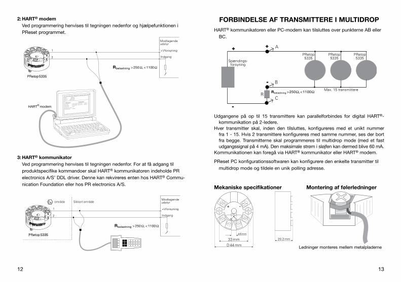
FORBINDELSE AF TRANSMITTERE I MULTIDROPHART®.kommunikatoren.eller.PC-modem.kan.tilsluttes.over.punkterne.AB.eller.
BC.
Udgangene. på. op. til. 15. transmittere. kan. parallelforbindes. for. digital. HART®-kommunikation.på.2-ledere..
Hver. transmitter. skal,. inden. den. tilsluttes,. konfigureres. med. et. unikt. nummer.fra.1.-.15..Hvis.2.transmittere.konfigureres.med.samme.nummer,.ses.der.bort.fra.begge..Transmitterne.skal.programmeres. til.multidrop.mode. (med.et. fast.udgangssignal.på.4.mA)..Den.maksimale.strøm.i.sløjfen.kan.dermed.blive.60.mA..
Kommunikationen.kan.foregå.via.HART®.kommunikator.eller.HART®.modem.
PReset.PC.konfigurationssoftwaren.kan.konfigurere.den.enkelte.transmitter.til.multidrop.mode.og.tildele.en.unik.polling.adresse.
Mekaniske specifikationer Montering af følerledninger
R
A
B
C
PRetop 5335
+
-
+
-
PRetop 5335
PRetop 5335
Spændings- forsyning
Max. 15 transmittere Rbelastning > 250 Ω, < 1100 Ω
Ledninger.monteres.mellem.metalpladerne
2: HART® modemVed.programmering.henvises.til.tegningen.nedenfor.og.hjælpefunktionen.i..PReset.programmet.
3: HART® kommunikatorVed.programmering.henvises.til.tegningen.nedenfor..For.at.få.adgang.til.produktspecifike.kommandoer.skal.HART®.kommunikatoren.indeholde.PR.elec.tronics.A/S’.DDL.driver..Denne.kan.rekvireres.enten.hos.HART®.Commu-nica.tion.Foundation.eller.hos.PR.electronics.A/S.
P R e t o p 5 3 3 5
1
2
F i l e P r o d u c t I n p u t O u t p u t C o m m u n i c a t i o n L a n g u a g e O p t i o n 0 8 : 3 0 : 0 0
P R e t o p 5 3 3 1
D a t e : 1 9 9 4 - 8 - 1 0
9 4 3 2 0 1 5 9 4
P R e l e c t r o n i c s
A n a l o g i n p u t A n a l o g o u t p u t
S e r i a l n o :
I n p u t t y p e : O u t p u t t y p e : 4 - 2 0 m A
U p s c a l e S e n s o r e r r o r : P t 1 0 0 D I N / I E C
0 . 0 0 - 5 0 . 0 0 C
3 - w i r e
1 . 0 0 s e c - - - - - -
I n p u t r a n g e :
C o n n e c t i o n :
C o l d j u n c t i o n c o m p :
R e s p o n s e t i m e :
T a g n o :
+Vforsyning
Indgang
Rbelastning > 250 Ω, < 1100 Ω
HART® modem
Modtagende udstyr
P R e t o p 5 3 3 5
1
2
Sikkert område
+Vforsyning
Indgang
Modtagende udstyr område
Rbelastning > 250 Ω, < 1100 Ω

14 15
2-WIRE TRANSMITTER WITH HART® PROTOCOL
PRetop 5335
CONTENTS
EC.declaration.of.conformity.............................................. . 16Application.......................................................................... . 17Technical.characteristics..................................................... . 17Mounting./.installation......................................................... . 17Applications......................................................................... . 18Order:.5335......................................................................... . 19Electrical.specifications....................................................... . 19Connections........................................................................ . 23Block.diagram..................................................................... . 24Programming....................................................................... . 25Connection.of.transmitters.in.multidrop.mode................... . 27Mechanical.specifications................................................... . 27Mounting.of.sensor.wires.................................................... . 27Appendix............................................................................. . 57ATEX.Installation.Drawings.-.5335A,.UK,.FR,.DE,.DK........ . 58ATEX.Installation.Drawings.-.5335D,.UK,.FR,.DE,.DK........ . 62FM.Installation.Drawing.No..5300Q502.............................. . 70CSA.Installation.Drawing.No..533XQC03........................... . 72INMETRO.Instruções.de.Segurança................................... . 74

16 17
2-WIRE TRANSMITTER WITH HART® PROTOCOL
PRetop 5335
• RTD, TC, Ohm, or mV input • Extremely high measurement accuracy • HART® communication• Galvanic isolation • For DIN form B sensor head mounting
Application
•. Linearised.temperature.measurement.with.Pt100...Pt1000,.Ni100...Ni1000,.or.TC.sensor.
•. Difference.or.average.temperature.measurement.of.2.resistance.or.TC.sensors.
•. Conversion.of.linear.resistance.variation.to.a.standard.analogue.current..signal,.for.instance.from.valves.or.Ohmic.level.sensors.
•. Amplification.of.a.bipolar.mV.signal.to.a.standard.4...20.mA.current.signal..
•. Connection.of.up.to.15.transmitters.to.a.digital.2-wire.signal.with.HART®.communication.
Technical characteristics
•. Within.a.few.seconds.the.user.can.program.PR5335.to.measure.temperatures.within.all.ranges.defined.by.the.norms.
•. The.RTD.and.resistance.inputs.have.cable.compensation.for.2-,.3-.and.4-wire.connection.
•. The.5335.has.been.designed.according.to.strict.safety.requirements.and.is.thus.suitable.for.application.in.SIL.2.installations.
•. Continuous.check.of.vital.stored.data.for.safety.reasons.
•. Sensor.error.detection.according.to.the.guidelines.in.NAMUR.NE.89.
Mounting / installation
•. For.DIN.form.B.sensor.head.mounting..In.non-hazardous.areas.the.5335.can.be.mounted.on.a.DIN.rail.with.the.PR.fitting.type.8421.
•. NB:.As.Ex.barrier.for.5335D.we.recommend.5106B.
EC DECLARATION OF CONFORMITyAs.manufacturer
PR electronics A/S Lerbakken 10 DK-8410 Rønde
hererby.declares.that.the.following.product:.Type: 5335 Name: 2-Wire transmitter with HART® protocol
is.in.conformity.with.the.following.directives.and.standards:
The.EMC.Directive.2004/108/EC.and.later.amendmentsEN 61326-1 : 2006
For.specification.of.the.acceptable.EMC.performance.level,.refer.to.the.electrical.specifications.for.the.module.
The.ATEX.Directive.94/9/EC.and.later.amendmentsEN 60079-0 : 2006, EN 60079-11 : 2007, EN 60079-15 : 2005 and EN 60079-26 : 2007 EN 61241-0 : 2006 and EN 61241-11 : 2006ATEX certificate: KEMA 03ATEX1508 X (5335A) ATEX certificate: KEMA 03ATEX1537 (5335D)
Notified.bodyKEMA Quality B.v. (0344) Utrechtseweg 310, 6812 AR Arnhem P.O. Box 5185, 6802 ED Arnhem The Netherlands
Rønde,.18.December.2009. Kim.Rasmussen.. Manufacturer’s.signature

18 19
Electrical specificationsSpecifications range:-40°C.to.+85°CCommon specifications:Supply.voltage,.DC.. Standard................................................ 8.0...35.V. CSA,.FM.&.ATEX.................................... 8.0...30.VIsolation.voltage,.test./.operation................. 1.5.kVAC./.50.VACWarm-up.time................................................ 30.sCommunications.interface............................HART®.and.Loop.LinkSignal./.noise.ratio........................................Min..60.dB.Response.time.(programmable).................... 1...60.sEEprom.error.check......................................<.10.sSignal.dynamics,.input.................................. 22.bitSignal.dynamics,.output............................... 16.bitCalibration.temperature................................ 20...28°C.Accuracy,.the.greater.of.general.and.basic.values:
+
-
+
-
V +
m A
V +
m A
+
-
+
-
V +
m A
+
-
+
-
V +
m A
V +
m A
+
-
+
-
+
-
+
-
+ -
+ -
+ -
+ -
+ -
+ -
2
1
2
2
1
1
RTD to 4...20 mA
TC to 4...20 mA
Resistance to 4...20 mA
Difference or average RTD, TC or mV
2-wire installation in control room
2-wire installation in control room
2-wire installation in control room
2-wire installation in control room
mV to 4...20 mA 2-wire installation in control room
Order: 5335
Type version
5335 Standard. :.A.CSA,.FM.&.ATEX. :.D.
APPLICATIONS
general values
.Input.type
Absolute.accuracy
Temperature.coefficient
All ≤.±0.05%.of.span ≤.±0.005%.of.span./.°C.

20 21
TC input:
Cold.junction.compensation.........................<.±1.0°CExternal.CjC.with.Ni100.or.Pt100................ -40.≤.Tamb..≤.135°CSensor.error.detection..................................YesSensor.error.current:.. When.detecting......................................Nom..33.μA. Else........................................................ 0.μAShort.circuit.detection................................... If.0%.>.5.mVvoltage input:Measurement.range...................................... -800...+800.mVMin..span....................................................... 2.5.mVInput.resistance............................................. 10.MΩCurrent output:Signal.range.................................................. 4...20.mA.Min..signal.range........................................... 16.mAUpdating.time................................................ 440.ms. . (660.ms.for.diff.)Fixed.output.signal........................................Between.4.and.20.mAOutput.signal.at.EEprom.error......................≤ 3.5.mALoad.resistance.............................................≤ (Vsupply.-.8)./.0.023.[Ω ]Load.stability.................................................<.±0.01%.of.span./.100.ΩSensor error detection:Programmable............................................... 3.5...23.mANAMUR.NE43.Upscale................................. 23.mANAMUR.NE43.Downscale............................. 3.5.mA
Of span =.Of.the.presently.selected.range
Effect.of.supply.voltage.variation..................<.0.005%.of.span./.VDCVibration........................................................ IEC.60068-2-6.Test.FCLloyd’s.specification.no..1............................ 4.g./.2...100.HzMax..wire.size................................................ 1.x.1.5.mm2..stranded.wireRelative.humidity...........................................<.95%.RH.(non-cond.)Dimensions....................................................Ø.44.x.20.2.mmProtection.degree.(enclosure./.terminals)..... IP68./.IP00Weight........................................................... 50.gElectrical specifications, input:Max..offset.................................................... 50%.of.selec..numerical.max..valueRTD and linear resistance input:
Cable.resistance.per.wire.(max.)................... 5.ΩSensor.current...............................................Nom..0.2.mAEffect.of.sensor.cable.resistance.(3-./.4-wire)....................................................<.0.002.Ω/ΩSensor.error.detection..................................YesShort.circuit.detection................................... If.0%.>.30.Ω
.Type
Min..temperature
Max..temperature
Min..span
.Standard
B.E.j.K.L.N.R.S.T.U.
W3.W5
+400°C.-100°C.-100°C.-180°C.-100°C.-180°C.
-50°C.-50°C.
-200°C.-200°C.
0°C.0°C
+1820°C.+1000°C.+1200°C.+1372°C.
+900°C.+1300°C.+1760°C.+1760°C.
+400°C.+600°C.
+2300°C.+2300°C
100°C.50°C.50°C.50°C.50°C.50°C.
100°C.100°C.
50°C.50°C.
100°C.100°C
IEC584.IEC584.IEC584.IEC584.
DIN.43710.IEC584.IEC584.IEC584.IEC584.
DIN.43710.ASTM.E988-90.ASTM.E988-90
RTD.type
Min..value
Max..value
Min..span Standard
Pt100.Ni100.Lin..R
-200°C.-60°C.
0.W
+850°C.+250°C.7000.W
10°C.10°C.10.W
IEC.60751.DIN.43760.
-----
Basic values
.Input.type
Basic.accuracy
Temperature.coefficient
Pt100.and.Pt1000 ≤.±0.1°C ≤.±0.005°C/°C
Ni100 ≤.±0.2°C ≤.±0.005°C/°C
Lin..R ≤.±0.1.Ω ≤.±5.mW./.°C
Volt ≤.±10.µV ≤.±0.5.µV./.°C
TC.type:.E,.j,.K,.L,.N,.T,.U
.≤.±0.5°C
.≤.±0.025°C./.°C
TC.type:.B,.R,.S,.W3,.W5
.≤.±1°C
.≤.±0.1°C./.°C
EMC.immunity.influence.......................................<.±0.1%.of.spanExtended.EMC.immunity:NAMUR NE.21,.A.criterion,.burst.........................<.±1%.of.span

22 23
3 4 6 5 3 4 6 5 3 4 6 5 3 4 6 5
+ -
3 4 6 5
+ -
3 4 6 5
+ -
3 4 6 5 3 4 6 5
3 4 6 5 3 4 6 5
1 2
3 4 6 5
+
- 1
+
- 2
3 4 6 5
+
-
+
-
1 2
3 4 6 5
+
-
1
+
-
2
1 2
m A - +
Output: 2-wire installation
Input:
Resistance, 2-wire Resistance, 3-wire
RTD, 2-wire RTD, 3-wire RTD, 4-wire TC, internal CJC
TC, external CJC mV
Resistance, 4-wire
TC, difference or average,
with external CJC
mV, difference or average
RTD, difference or average
TC, difference or average,
with internal CJC
Ex appoval - 5335A:KEMA.03ATEX1508.X.................................... . II.3.GD.Ex.nA.[nL].IIC.T6...T4.or. . II.3.GD.Ex.nL.IIC.T6...T4.or. . II.3.GD.Ex.nA.[ic].IIC.T6...T4.or. . II.3.GD.Ex.ic.IIC.T6...T4. ATEX.Installation.Drawing.No................ 5335QA02
Ex / I.S. approval - 5335D:KEMA.03ATEX1537....................................... . II.1.G.Ex.ia.IIC.T4.or.T6. . II.1.D.Ex.iaDMax..amb..temperature.for.T1...T4............... 85°CMax..amb..temperature.for.T5.and.T6.......... 60°CATEX,.applicable.in.zone............................... 0,.1,.2,.20,.21.or.22. ATEX.Installation.Drawing.No................ 5335QE01
FM,.applicable.in........................................... IS,.Class.I,.Div..1,.Group.A,.B,.C,.D. IS,.Class.I,.Zone.0,.AEx.ia.IIC. FM.Installation.Drawing.No................... 5300Q502
CSA,.applicable.in......................................... IS,.Class.I,.Div..1,.Group.A,.B,.C,.D,. Ex.ia.IIC. IS,.Class.I,.Zone.0,.AEx.ia.IIC. CSA.Installation.Drawing.No................. 533XQC03
INMETRO.09/UL-BRCO-0002......................BR-Ex.ia.IIC.T4.or.T6.or. -40°C.≤.Tamb..≤.+85°C,.or. -40°C.≤.Tamb..≤.+60°C
Marine approval:Det.Norske.Veritas,.Ships.&.Offshore...........Standard.for.Certification.No..2.4gOST R approval:VNIIM.&.VNIIFTRI,.Cert..no...........................See.www.prelectronics.comObserved authority requirements: Standard:EMC.2004/108/EC........................................EN.61326-1ATEX.94/9/EC................................................EN.60079-0,.EN.60079-11,.. EN.60079-15.and.EN.60079-26.. EN.61241-0.and.EN.61241-11FM................................................................. 3600,.3611,.3610CSA,.CAN./.CSA...........................................C22.2.No..157,.E60079-11,.UL.913INMETRO...................................................... IEC.60079-0.and.IEC.60079-11
CONNECTIONS

24 25
PROgRAMMINgPRetop 5335 can be configured in the following 3 ways:
1..With.PR.electronics.A/S’.communications.interface.Loop.Link.and.PReset.PC.configuration.software..
2..With.a.HART®.modem.and.PReset.PC.configuration.software..
3..With.a.HART®.communicator.with.PR.electronics.A/S’.DDL.driver.
1: Loop LinkFor.programming.please.refer.to.the.drawing.below.and.the.help.functions.in.PReset..Loop.Link.is.not.approved.for.communication.with.modules.installed.in.hazardous.(Ex).areas.
1
2
*
*
PRetop 5335
LoopLink
5909 - USB5905 - RS232
File Product Input Output Communication Language Option 08:30:00
PRetop 5331
Date: 2004-8-10
043201594
PRelectronics
Analog inputAnalog output
Serial no:
Input type:Output type: 4 - 20mA
UpscaleSensor error:
Pt100 DIN/IEC
0.00 - 50.00 C
3-wire
1.00 sec------
Input range:
Connection:
Cold junction comp:
Response time:
Tag no:
Disconnect
+Vsupply
* Connected only for on-line programming
Black
Red Yellow
Green
Input
Receiving Equipment
Connector
0 . . .
1 6
m A
4 3
2
1
5 6 4 3
2
+ -
+ -
m V
m A
M U
X
4 m
A
5 3 3
5
PG
A
D /
A
A /
D
C P
U
E E
P R
O M
Inp
ut g
nd
.
Sup
ply
-
4...2
0 m
A
TC
Ext
. C
JC
mV
R
TD, l
in. R
- w
ire
Int.
C
JC
Ex circuit, only 5335D
Su
pp
ly +
8
.0..
.35
VD
C
Co
mm
.
BLOCK DIAgRAM

26 27
CONNECTION OF TRANSMITTERS IN MULTIDROP MODE
The.HART®.communicator.or.a.PC.modem.can.be.connected.accross.AB.or.BC.
The. outputs. of. max.. 15. transmitters. can. be. connected. in. parallel. for. a. digital.HART®.communication.on.2-wires..
Before.it.is.connected,.each.transmitter.must.be.configured.with.a.unique.number.from.1.to.15..If.2.transmitters.are.configured.with.the.same.number,.both.will.be.excluded..The.transmitters.must.be.programmed.for.multidrop.mode.(with.a.fixed.output.signal.of.4.mA)..Maximum.current.in.the.loop.is.therefore.60.mA..
The.communication. is.either.by.means.of.a.HART®.communicator.or.a.HART®.modem..
The.PReset.PC.configuration.software.can.configure.the.individual.transmitter.for.multidrop.mode.and.provide.it.with.a.unique.polling.address.
Mechanical specifications Mounting of sensor wires
R
A
B
C
PRetop 5335
+
-
+
-
PRetop 5335
PRetop 5335
Power supply
Max. 15 transmitters Rload > 250 Ω, < 1100 Ω
Wires.must.be.mounted.between.the.metal.plates.
2: HART® modemFor.programming.please.refer.to.the.drawing.below.and.the.help.functions.in.PReset.
3: HART® communicatorFor.programming.please.refer.to.the.drawing.below..To.gain.access.to.product-specific.commands,.the.HART®.communicator.must.be.loaded.with.the.PR.electronics.A/S.DDL.driver..This.can.be.ordered.either.at.the.HART®.Communica.tion.Foundation.or.at.PR.electronics.A/S.
P R e t o p 5 3 3 5
1
2
F i l e P r o d u c t I n p u t O u t p u t C o m m u n i c a t i o n L a n g u a g e O p t i o n 0 8 : 3 0 : 0 0
P R e t o p 5 3 3 1
D a t e : 1 9 9 4 - 8 - 1 0
9 4 3 2 0 1 5 9 4
P R e l e c t r o n i c s
A n a l o g i n p u t A n a l o g o u t p u t
S e r i a l n o :
I n p u t t y p e : O u t p u t t y p e : 4 - 2 0 m A
U p s c a l e S e n s o r e r r o r : P t 1 0 0 D I N / I E C
0 . 0 0 - 5 0 . 0 0 C
3 - w i r e
1 . 0 0 s e c - - - - - -
I n p u t r a n g e :
C o n n e c t i o n :
C o l d j u n c t i o n c o m p :
R e s p o n s e t i m e :
T a g n o :
+Vsupply
Input
Receiving Equipment
Rload > 250 Ω, < 1100 Ω
HART® modem
P R e t o p 5 3 3 5
1
2
Safe area
+Vsupply
Input
Receiving Equipment area
Rload > 250 Ω, < 1100 Ω

28 29
TRANSMETTEUR 2-FILS AvEC PROTOCOLE HART®
PRetop 5335
SOMMAIRE
Déclaration.de.conformité.CE............................................. . 30Application.......................................................................... . 31Caractéristiques.techniques............................................... . 31Montage./.installation.......................................................... . 31Applications......................................................................... . 32Référence.:.5335.................................................................. . 33Spécifications...................................................................... . 33Connexions......................................................................... . 37Schéma.de.principe............................................................ . 38Programmation.................................................................... . 39Raccordement.des.transmetteurs.en.multi-addressage.... . 41Dimensions.mécaniques..................................................... . 41Montage.des.fils.du.capteur............................................... . 41Appendix............................................................................. . 57ATEX.Installation.Drawings.-.5335A,.UK,.FR,.DE,.DK........ . 58ATEX.Installation.Drawings.-.5335D,.UK,.FR,.DE,.DK........ . 62FM.Installation.Drawing.No..5300Q502.............................. . 70CSA.Installation.Drawing.No..533XQC03........................... . 72INMETRO.Instruções.de.Segurança................................... . 74

30 31
TRANSMETTEUR 2-FILS AvEC PROTOCOLE HART®
PRetop 5335
• Entrée RTD, TC, Ohm ou mV • Très grande précision de mesure • Communication avec protocole HART®
• Isolation galvanique • Pour tête de sonde DIN B
Application
•. Mesure.linéarisée.de.la.température.avec.un.capteur.Pt100...Pt1000,Ni100...Ni1000.ou.de.thermocouples.
•. Mesure.de.la.température.différentielle.ou.moyenne.avec.2.sondes.résistives.ou.thermocouples.
•. Conversion.d’une.résistance.linéaire.en.un.signal.courant.standard.analogique.pour.mesurer.par.exemple.le.niveau.ou.la.position.d’une.vanne.
•. Amplification.d’un.signal.mV.bipolaire.en.un.signal.courant.standard.de.4...20.mA.
•. Connexion.en.parallèle.de.15.transmetteurs.au.maximum.pour.une.communication.digitale.avec.le.protocole.HART®.
Caractéristiques techniques
•. Le.PR5335.peut.être.programmé.de.manière.simple.et.rapide.
•. Compensation.de.ligne.pour.des.entrées.RTD.et.résistance.avec.un.raccordement.à.2,.3.et.4.fils.
•. Le.5335.a.été.construit.avec.un.niveau.de.sécurité.élevé.permettant.de.l’utili-ser.dans.les.installations.classées.SIL.2.
•. Vérification.continue.des.données.sauvegardés.
•. Détection.de.rupture.sonde.selon.les.recommandations.NAMUR.NE.89.
Montage / installation
•. Pour.tête.de.sonde.DIN.B..En.zone.non-dangereuse.le.5335.peut.être.monté.sur.rail.DIN.avec.le.support.PR.type.8421.
•. N.B. :.Comme.barrière.S.I..pour.le.5335D.nous.recommandons.le.PR5106B.
DECLARATION DE CONFORMITE CEEn.tant.que.fabricant
PR electronics A/S Lerbakken 10 DK-8410 Rønde
déclare.que.le.produit.suivant.:Type : 5335 Nom : Transmetteur 2-fils avec protocole HART®
correspond.aux.directives.et.normes.suivantes.:
La.directive.CEM.(EMC).2004/108/CE.et.les.modifications.subséquentesEN 61326-1 : 2006
. Pour.une.spécification.du.niveau.de.rendement.acceptable.CEM.(EMC)..renvoyer.aux.spécifications.électriques.du.module.
La.directive.ATEX.94/9/CE.et.les.modifications.subséquentesEN 60079-0 : 2006, EN 60079-11 : 2007, EN 60079-15 : 2005 et EN 60079-26 : 2007 EN 61241-0 : 2006 et EN 61241-11 : 2006 Certificat ATEX : KEMA 03ATEX1508 X (5335A) Certificat ATEX : KEMA 03ATEX1537 (5335D)
Organisme.notifié.KEMA Quality B.v. (0344) Utrechtseweg 310, 6812 AR Arnhem P.O. Box 5185, 6802 ED Arnhem The Netherlands
Rønde,.le.18.décembre.2009. Kim.Rasmussen.. Signature.du.fabricant

32 33
SpécificationsPlage de température :-40°C.à.+85°CSpécifications communes :Tension.d’alimentation.cc.. Standard................................................ 8,0...35.V. CSA,.FM.&.ATEX.................................... 8,0...30.VTension.d’isolation,.test./.opération.............. 1,5.kVca./.50.VcaTemps.de.chauffe.......................................... 30.sKit.de.programmation...................................HART®.et.Loop.LinkRapport.signal./.bruit....................................Min..60.dB.Temps.de.réponse.(programmable).............. 1...60.sVérification.de.l’EEprom................................<.10.sDynamique.du.signal.d’entrée...................... 22.bitDynamique.du.signal.de.sortie..................... 16.bitTempérature.d’étalonnage............................ 20...28°C.Précision,.la.plus.grande.des.valeurs.générales.et.de.base.:
+
-
+
-
V +
m A
V +
m A
+
-
+
-
V +
m A
+
-
+
-
V +
m A
V +
m A
+
-
+
-
+
-
+
-
+ -
+ -
+ -
+ -
+ -
+ -
2
1
2
2
1
1
RTD en 4...20 mA
Différence ou moyen RTD, TC ou mV
mV en 4...20 mA
Résistance en 4...20 mA
TC en 4...20 mA Installation 2-fils en salle de contrôle
Installation 2-fils en salle de contrôle
Installation 2-fils en salle de contrôle
Installation 2-fils en salle de contrôle
Installation 2-fils en salle de contrôle
Référence : 5335
Type version
5335 Standard. :.A.CSA,.FM.&.ATEX. :.D.
APPLICATIONS
valeurs générales
Type.d’entrée
Précision.absolue
Coefficient.de.température
Tous ≤.±0,05%.de.l’EC ≤.±0,005%.de.l’EC./.°C.

34 35
Entrée TC :
Compensation.de.soudure.froide.(CSF).......<.±1,0°CCSF.externe.avec.Ni100.ou.Pt100............... -40.≤.Tamb..≤.135°CDétection.de.rupture.sonde..........................OuiCourant.de.sonde.:.. Pendant.la.détection..............................Nom..33.μA. Si.non..................................................... 0.μADétection.de.court-circuit.............................Si.0%.>.5.mVEntrée tension :Gamme.de.mesure........................................ -800...+800.mVPlage.de.mesure.min.................................... 2,5.mVRésistance.d’entrée...................................... 10.MΩSortie courant :Gamme.de.mesure........................................ 4...20.mA.Plage.de.mesure.min.................................... 16.mATemps.de.scrutation...................................... 440.ms. (660.ms.pour.diff.)Signal.sortie.fixe............................................Entre.4.et.20.mASortie.en.cas.de.corruption.de.l’EEprom......≤ 3,5.mARésistance.de.charge....................................≤ (Valim..-.8)./.0,023.[Ω ]Stabilité.de.charge........................................<.±0,01%.de.l’EC./.100.ΩDétection de rupture de sonde :Programmable............................................... 3,5...23.mANAMUR.NE43.Haut.d’échelle........................ 23.mANAMUR.NE43.Bas.d’échelle.......................... 3,5.mA
EC =.Echelle.configurée
Effet.d’une.variation.de.la.tension.d’alimentation..........................<.0,005%.de.l’EC./.VccVibration........................................................ IEC.60068-2-6.Test.FCLloyd.specification.no..1............................... 4.g./.2...100.HzTaille.max..des.fils......................................... 1.x.1,5.mm2..fil.multibrinsHumidité........................................................<.95%.HR.(sans.cond.)Dimensions....................................................Ø.44.x.20,2.mmDegré.de.protection.(boîtier./.bornier).......... IP68./.IP00Poids............................................................. 50.gSpécifications électriques, entrée :Décalage.max............................................... 50%.de.la.valeur.num..max..sélec.Entrée RTD et entrée résistance linéaire :
Résistance.de.ligne.max..par.fil.................... 5.ΩCourant.de.sonde.........................................Nom..0,2.mAEffet.de.la.résistance.de.ligne.(3-./.4-fils)......<.0,002.Ω/ΩDétection.de.rupture.sonde..........................OuiDétection.de.court-circuit.............................Si.0%.>.30.Ω
.Type
Température.min.
Température.max.
Plage.min.
.Standard
B.E.j.K.L.N.R.S.T.U.
W3.W5
+400°C.-100°C.-100°C.-180°C.-100°C.-180°C.
-50°C.-50°C.
-200°C.-200°C.
0°C.0°C
+1820°C.+1000°C.+1200°C.+1372°C.
+900°C.+1300°C.+1760°C.+1760°C.
+400°C.+600°C.
+2300°C.+2300°C
100°C.50°C.50°C.50°C.50°C.50°C.
100°C.100°C.
50°C.50°C.
100°C.100°C
IEC584.IEC584.IEC584.IEC584.
DIN.43710.IEC584.IEC584.IEC584.IEC584.
DIN.43710.ASTM.E988-90.ASTM.E988-90
Type.RTD
Valeur.min.
Valeur.max.
Plage.min. Standard
Pt100.Ni100.R.lin.
-200°C.-60°C.
0.W
+850°C.+250°C.7000.W
10°C.10°C.25.W
IEC.60751.DIN.43760.
-----
valeur de base
Type.d’entrée
Précision.de.base
Coefficient.de.température
Pt100.et.Pt1000 ≤.±0,1°C ≤.±0,005°C/°C
Ni100 ≤.±0,2°C ≤.±0,005°C/°C
R.lin. ≤.±0,1.Ω ≤.±5.mW./.°C
Volt ≤.±10.µV ≤.±0,5.µV./.°C
Type.TC.:.E,.j,.K,.L,.N,.T,.U
.≤.±0,5°C
.≤.±0,025°C./.°C
Type.TC.:.B,.R,.S,.W3,.W5
.≤.±1°C
.≤.±0,1°C./.°C
Immunité.CEM.......................................................<.±0,1%.de.l’ECImmunité.CEM.améliorée.:NAMUR.NE.21,.critère.A,.burst............................<.±1%.de.l’EC

36 37
3 4 6 5 3 4 6 5 3 4 6 5 3 4 6 5
+ -
3 4 6 5
+ -
3 4 6 5
+ -
3 4 6 5 3 4 6 5
3 4 6 5 3 4 6 5
1 2
3 4 6 5
+
- 1
+
- 2
3 4 6 5
+
-
+
-
1 2
3 4 6 5
+
-
1
+
-
2
1 2
m A - +
Sortie : Installation 2-fils
Entrée :
Résistance, 2-fils Résistance, 3-fils
RTD, 2-fils RTD, 3-fils RTD, 4-fils TC, CSF interne
TC, CSF externe mV
Résistance, 4-fils
TC, différence ou moyen
avec CSF externe
mV, différence ou moyen
RTD, différence ou moyen
TC, différence ou moyen
avec CSF interne
Approbation Ex 5335A :KEMA.03ATEX1508.X.................................... . II.3.GD.Ex.nA.[nL].IIC.T6...T4.ou. . II.3.GD.Ex.nL.IIC.T6...T4.ou. . II.3.GD.Ex.nA.[ic].IIC.T6...T4.ou. . II.3.GD.Ex.ic.IIC.T6...T4. ATEX.Installation.Drawing.No................ 5335QA02
Approbation Ex / S.I. - 5335D :KEMA.03ATEX1537....................................... . II.1.G.Ex.ia.IIC.T4.ou.T6. . II.1.D.Ex.iaDTempérature.amb..max..(T1...T4).................. 85°CTempérature.amb..max..(T5.et.T6)................ 60°CATEX,.applicable.en.zone.............................. 0,.1,.2,.20,.21.ou.22. ATEX.Installation.Drawing.No................ 5335QE01
FM,.applicable.en.......................................... IS,.Class.I,.Div..1,.Group.A,.B,.C,.D. IS,.Class.I,.Zone.0,.AEx.ia.IIC. FM.Installation.Drawing.No................... 5300Q502
CSA,.applicable.en........................................ IS,.Class.I,.Div..1,.Group.A,.B,.C,.D,. Ex.ia.IIC.. IS,.Class.I,.Zone.0,.AEx.ia.IIC. CSA.Installation.Drawing.No................. 533XQC03
INMETRO.09/UL-BRCO-0002......................BR-Ex.ia.IIC.T4.ou.T6.ou. -40°C.≤.Tamb..≤.+85°C,.ou. -40°C.≤.Tamb..≤.+60°C
Approbation marine :Det.Norske.Veritas,.Ships.&.Offshore...........Standard.for.Certification.No..2.4Approbation gOST R :VNIIM.&.VNIIFTRI,.Cert..no...........................Voir.www.prelectronics.frAgréments et homologations : Standard :EMC.2004/108/CE........................................EN.61326-1ATEX.94/9/CE................................................EN.60079-0,.EN.60079-11,.. EN.60079-15.et.EN.60079-26.. EN.61241-0.et.EN.61241-11FM.................................................................3600,.3611,.3610.CSA,.CAN./.CSA...........................................C22.2.No..157,.E60079-11,.UL.913INMETRO...................................................... IEC.60079-0.et.IEC.60079-11
CONNEXIONS

38 39
1
2
*
*
PRetop 5335
LoopLink
5909 - USB5905 - RS232
File Product Input Output Communication Language Option 08:30:00
PRetop 5331
Date: 2004-8-10
043201594
PRelectronics
Analog inputAnalog output
Serial no:
Input type:Output type: 4 - 20mA
UpscaleSensor error:
Pt100 DIN/IEC
0.00 - 50.00 C
3-wire
1.00 sec------
Input range:
Connection:
Cold junction comp:
Response time:
Tag no:
Débranché
+Valim.
* Connexion facultative
Noir
Rouge Jaune
Verte
Entrée
API ou autres
Connecteur
PROgRAMMATIONLe PRetop 5335 peut être programmé des 3 manières suivantes :
1..Avec.le.kit.de.programmation.Loop.Link.et.le.logiciel.PReset.de.PR.elec-tronics.A/S.
2..Avec.le.modem.HART®.et.le.logiciel.PReset.
3..Avec.le.communicateur.HART®.chargé.avec.le.DDL.de.PR.electronics.A/S.
1 : Loop LinkPour.le.raccordement.du.Loop.Link,.veuillez.vous.reporter.au.schéma.ci-dessous.et.à.l’aide.en.ligne.du.logiciel.PReset..Loop.Link.ne.doit.pas.être.utilisé.pour.communication.avec.des.modules.installés.en.zone.dangereuse.
0 . . .
1 6
m A
4 3
2
1
5 6 4 3
2
+ -
+ -
m V
m A
M U
X
4 m
A
5 3 3
5
PG
A
D /
A
A /
D
C P
U
E E
P R
O M
En
tré
e m
asse
Alim
enta
tion
-
4...2
0 m
A
TC
CS
F ex
t.
mV
R
TD, R
. lin
. - f
il
CS
F in
t.
Circuit S.I., seulement 5335D
Alim
en
tati
on
+
8,0
...3
5 V
cc
Co
mm
.
SCHEMA DE PRINCIPE

40 41
RACCORDEMENT DES TRANSMETTEURS EN MULTI-ADDRESSAgE
Le.communicateur.HART®.ou.le.modem.peuvent.être.connectés.sur.les.points.AB.ou.sur.les.points.BC.
Pour.la.communication.digitale.HART®.de.2-fils,.les.sorties.de.15.transmetteurs.au.maximum.peuvent.être.connectés.en.parallèle.
Chaque. transmetteur. sera. doté. d’un. numéro. unique. entre. 1. et. 15.. Si. 2.transmetteurs.ont.le.même.numéro,.tous.les.deux.seront.ignorés..Programmés.pour.multi-addressage,.les.sorties.des.transmetteurs.seront.bloquées.à.4.mA,.et.le.courant.max..dans.la.boucle.sera.donc.de.60.mA..
La. communication. se. fait. ensuite. soit. avec. le. communicateur. HART®. ou. le.modem.HART®..
Le.logiciel.PReset.peut.configurer.le.transmetteur.individuel.en.multi-addressage.et.lui.donner.un.addressage.unique.
Dimensions mécaniques Montage des fils du capteur
R
A
B
C
PRetop 5335
+
-
+
-
PRetop 5335
PRetop 5335
Alimentation
Jusqu'à 15 transmetteurs Rcharge > 250 Ω, < 1100 Ω
Les.fils.doivent.être.montés.entre.les.plaques.métalliques.
2 : Modem HART®
Pour.le.raccordement.veuillez.vous.reporter.au.schéma.ci-dessous.et.à.l’aide.en.ligne.du.logiciel.PReset.
3 : Communicateur HART®
Pour.le.raccordement.veuillez.vous.reporter.au.schéma.ci-dessous..Pour.avoir.accès.à.tous.les.paramètres,.le.communicateur.HART®.doit.être.chargé.avec.le.DDL.spécifique.du.PR.electronics.A/S..Ce.DDL.peut.être.commandé.chez.PR.electronics.A/S.ou.chez.la.Fondation.HART®.
P R e t o p 5 3 3 5
1
2
F i l e P r o d u c t I n p u t O u t p u t C o m m u n i c a t i o n L a n g u a g e O p t i o n 0 8 : 3 0 : 0 0
P R e t o p 5 3 3 1
D a t e : 1 9 9 4 - 8 - 1 0
9 4 3 2 0 1 5 9 4
P R e l e c t r o n i c s
A n a l o g i n p u t A n a l o g o u t p u t
S e r i a l n o :
I n p u t t y p e : O u t p u t t y p e : 4 - 2 0 m A
U p s c a l e S e n s o r e r r o r : P t 1 0 0 D I N / I E C
0 . 0 0 - 5 0 . 0 0 C
3 - w i r e
1 . 0 0 s e c - - - - - -
I n p u t r a n g e :
C o n n e c t i o n :
C o l d j u n c t i o n c o m p :
R e s p o n s e t i m e :
T a g n o :
+Valim.
Entrée
API ou autres
Rcharge > 250 Ω, < 1100 Ω
Modem HART®
P R e t o p 5 3 3 5
1
2
Zone non dangereuse
+Valim.
Entrée
API ou autres Zone
Rcharge > 250 Ω, < 1100 Ω

42 43
2-DRAHT MESSUMFORMER MIT HART® PROTOKOLL
PRetop 5335
Inhaltsverzeichnis
EG-Konformitätserklärung................................................... . 44Verwendung......................................................................... . 45Technische.Merkmale.......................................................... . 45Montage./.Installation.......................................................... . 45Anwendungen..................................................................... . 46Bestellangaben:.5335.......................................................... . 47Elektrische.Daten................................................................ . 47Anschlüsse.......................................................................... . 51Blockdiagramm................................................................... . 52Programmierung.................................................................. . 53Parallelanschluss.von.Signalgebern.(Multidrop)................. . 55Abmessungen..................................................................... . 55Montage.von.Fühlerleitungen.............................................. . 55Appendix............................................................................. . 57ATEX.Installation.Drawings.-.5335A,.UK,.FR,.DE,.DK........ . 58ATEX.Installation.Drawings.-.5335D,.UK,.FR,.DE,.DK........ . 62FM.Installation.Drawing.No..5300Q502.............................. . 70CSA.Installation.Drawing.No..533XQC03........................... . 72INMETRO.Instruções.de.Segurança................................... . 74
44 45
2-DRAHT MESSUMFORMER MIT HART® PROTOKOLL
PRetop 5335
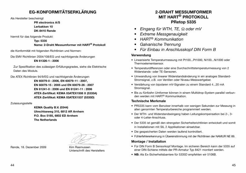
• Eingang für WTH, TE, Ω oder mV• Extreme Messgenauigkeit • HART® Kommunikation• Galvanische Trennung • Für Einbau in Anschlusskopf DIN Form B
verwendung•. Linearisierte.Temperaturmessung.mit.Pt100...Pt1000,.Ni100...Ni1000.oder.
Thermoelementsensor.
•. Temperaturdifferenzen.oder.eine.Durchschnittstemperaturmessung.von.2.Widerstands-.oder.TE-Sensoren.
•. Umwandlung.von.linearer.Widerstandsänderung.in.ein.analoges.Standard-Stromsignal,.z.B..von.Ventilen.oder.Niveau-Messwertgeber.
•. Verstärkung.von.bipolaren.mV-Signalen.zu.einem.Standard.4...20.mA.Stromsignal..
•. Bis.zu.fünfzehn.Umformer.können.in.einem.Multidrop-System.parallel.verbun-den.werden.mit.HART®.Kommunikation.
Technische Merkmale•. PR5335.kann.vom.Benutzer.innerhalb.von.wenigen.Sekunden.zur.Messung.in.
allen.genormten.Temperaturbereiche.programmiert.werden..
•. Der.WTH-.und.Widerstandseingang.haben.Leitungskompensation.bei.2-,.3-.oder.4-Leiter-Anschluss.
•. Der.5335.ist.gemäß.den.strengsten.Sicherheitsrichtlinien.entwickelt.und.somit.in.Installationen.mit.SIL.2.Applikationen.einsetzbar.
•. Die.gespeicherten.Daten.werden.laufend.kontrolliert.
•. Fühlerfehlererkennung.in.Übereinstimmung.mit.der.Richtlinien.der.NAMUR.NE.89.
Montage / Installation•. Für.DIN.Form.B.Sensorkopf.Montage..Im.sicheren.Bereich.kann.der.5335.auf.
einer.DIN-.Schiene.mittels.der.PR-Armatur.Typ.8421.montiert.werden..
•. NB: Als.Ex-Sicherheitsbarriere.für.5335D.empfehlen.wir.5106B.
Eg-KONFORMITäTSERKLäRUNgAls.Hersteller.bescheinigt
PR electronics A/S Lerbakken 10 DK-8410 Rønde
hiermit.für.das.folgende.Produkt:Typ: 5335 Name: 2-Draht Messumformer mit HART® Protokoll
die.Konformität.mit.folgenden.Richtlinien.und.Normen:
Die.EMV.Richtlinien.2004/108/EG.und.nachfolgende.ÄnderungenEN 61326-1 : 2006
. Zur.Spezifikation.des.zulässigen.Erfüllungsgrades,.siehe.die.Elektrische.Daten.des.Moduls.
Die.ATEX.Richtlinien.94/9/EG.und.nachfolgende.ÄnderungenEN 60079-0 : 2006, EN 60079-11 : 2007, EN 60079-15 : 2005 und EN 60079-26 : 2007 EN 61241-0 : 2006 und EN 61241-11 : 2006 ATEX-Zertifikat: KEMA 03ATEX1508 X (5335A) ATEX-Zertifikat: KEMA 03ATEX1537 (5335D)
ZulassungsstelleKEMA Quality B.v. (0344) Utrechtseweg 310, 6812 AR Arnhem P.O. Box 5185, 6802 ED Arnhem The Netherlands
Rønde,.18..Dezember.2009. Kim.Rasmussen.. Unterschrift.des.Herstellers

46 47
Elektrische DatenSpezifikationsbereich:-40°C.bis.+85°Cgemeinsame Daten:Versorgungsspannung,.DC.. Standard................................................ 8,0...35.V. CSA,.FM.&.ATEX.................................... 8,0...30.VIsolationsspannung,.Test./.Betrieb................ 1,5.kVAC./.50.VACAufwärmzeit................................................... 30.sKommunikationsschnittstelle........................HART®.und.Loop.LinkSignal-./.Rauschverhältnis............................Min..60.dB.Ansprechzeit.(programmirbar)....................... 1...60.sEEprom.Fehlerkontrolle.................................<.10.sSignaldynamik,.Eingang................................ 22.BitSignaldynamik,.Ausgang............................... 16.BitKalibrierungstemperatur................................ 20...28°CGenauigkeit,.höherer.Wert.von.allgemeinen.und.Grundwerten:
+-
+-
V+
mA
V+
mA
+-
+-
V+
mA
+-
+-
V+
mA
V+
mA
+-
+-
+-
+-
+-
+-
+-
+-
+-
+-
21
2
21
1
WTH in 4...20 mA
Differenz oder MittelWTH, TE oder mV
mV in 4...20 mA
Widerstandin 4...20 mA
TE en 4...20 mA 2-Draht-Installationim Kontrollraum
2-Draht-Installationim Kontrollraum
2-Draht-Installationim Kontrollraum
2-Draht-Installationim Kontrollraum
2-Draht-Installationim Kontrollraum
Bestellangaben: 5335
Typ version
5335 Standard. :.A.CSA,.FM.&.ATEX. :.D.
ANWENDUNgEN
Allgemeine Werte
.Eingangsart
Absolute.Genauigkeit
Temperatur-.koeffizient
Alle ≤.±0,05%.d..Messsp. ≤.±0,005%.d..Messsp./°C.

48 49
TE-Eingang:
Vergleichstellenkompensation.(CjC).............<.±1,0°CExterne.CjC.mit.Ni100.oder.Pt100.............. -40.≤.TUmg..≤.135°CFühlerfehlererkennung................................... jaFühlerfehlerstrom:. Bei.Erkennung........................................Nom..33.µA. Sonst...................................................... 0.μAKurzschlusserkennung..................................Falls.0%.>.5.mVSpannungseingang:Messbereich.................................................. -800...+800.mVMin..Messbereich.(Spanne)........................... 2,5.mVEingangswiderstand...................................... 10.MΩStromausgang:Signalbereich................................................. 4...20.mAMin..Signalbereich......................................... 16.mAAktualisierungszeit........................................ 440.ms. (660.ms.für.Diff.)Festes.Ausgangssignal.................................Zwischen.4.und.20.mAAusgangssignal.bei.EEpromfehler................≤.3,5.mABelastungswiderstand...................................≤.(UVersorg..-.8)./.0,023.[Ω]Belastungsstabilität.......................................<.±0,01%.d..Messsp../.100.ΩSensorfehlanzeige:Programmierbar.......................................... . 3,5...23.mANAMUR.NE43.aufsteuernd......................... . 23.mANAMUR.NE43.zusteuernd.......................... . 3,5.mA
d. Messspanne.=.der.gewählten.Messspanne
Einfluss.von.Änderung.der.Versorgungsspannung...................................<.0,005%.d..Messsp../.VDCVibration........................................................ IEC.60068-2-6.Test.FCLloyd’s.Spezifikation.Nr..1............................. 4.g./.2...100.HzMax..Leitungsquerschnitt.............................. 1.x.1,5.mm2.LitzendrahtLuftfeuchtigkeit..............................................<.95%.RH.(nicht.kond.)Maß................................................................Ø.44.x.20,2.mmSchutzart.(Gehäuse./.Anschluss).................. IP68./.IP00Gewicht......................................................... 50.gElektrische Daten, Eingang:Max..Nullpunktverschiebung.(Offset)............ 50%.des.gew..num..Max.-WertesWTH- und Linearer Widerstandseingang:
Leitungswiderstand.pro.Leiter.(Max.)............ 5.ΩSensorstrom..................................................Nom..0,2.mAWirkung.des.Fühlerkabelwiderstandes..(3-./.4-Leiter).................................................<.0,002.Ω/ΩFühlerfehlererkennung................................... jaKurzschlusserkennung..................................Falls.0%.>.30.Ω
.Typ
Min..Temperatur
Max..Temperatur
Min..Spanne
.Norm
B.E.j.K.L.N.R.S.T.U.
W3.W5
+400°C.-100°C.-100°C.-180°C.-100°C.-180°C.
-50°C.-50°C.
-200°C.-200°C.
0°C.0°C
+1820°C.+1000°C.+1200°C.+1372°C.
+900°C.+1300°C.+1760°C.+1760°C.
+400°C.+600°C.
+2300°C.+2300°C
100°C.50°C.50°C.50°C.50°C.50°C.
100°C.100°C.
50°C.50°C.
100°C.100°C
IEC584.IEC584.IEC584.IEC584.
DIN.43710.IEC584.IEC584.IEC584.IEC584.
DIN.43710.ASTM.E988-90.ASTM.E988-90
WTH-.Typ
Min..Wert
Max..Wert
Min..Spanne Norm
Pt100.Ni100.Lin..R
-200°C.-60°C.
0.W
+850°C.+250°C.7000.W
10°C.10°C.25.W
IEC.60751.DIN.43760.
-----
Basisværdier
.Eingangsart
Grund-.Genauigkeit
Temperatur-.koeffizient
Pt100.und.Pt1000 ≤.±0,1°C ≤.±0,005°C/°C
Ni100 ≤.±0,2°C ≤.±0,005°C/°C
Lin..R ≤.±0,1.Ω ≤.±5.mW./.°C
Volt ≤.±10.µV ≤.±0,5.µV./.°C
TE-Typ:.E,.j,.K,.L,.N,.T,.U
.≤.±0,5°C
.≤.±0,025°C./.°C
TE-Typ:.B,.R,.S,.W3,.W5
.≤.±1°C
.≤.±0,1°C./.°C
EMV-Immunitätswirkung............................. .<.±0,1%.d..Messsp.Erweiterte.EMV-immunität:NAMUR.NE.21,.A.Kriterium,.Burst.............. .<.±1%.d..Messsp.

50 51
3 4 6 5 3 4 6 5 3 4 6 5 3 4 6 5
+ -
3 4 6 5
+ -
3 4 6 5
+ -
3 4 6 5 3 4 6 5
3 4 6 5 3 4 6 5
1 2
3 4 6 5
+
- 1
+
- 2
3 4 6 5
+
-
+
-
1 2
3 4 6 5
+
-
1
+
-
2
1 2
m A - +
Ausgang: 2-Draht-Installation
Eingang:
Widerst., 2-Leiter Widerst., 3-Leiter
WTH, 2-Leiter WTH, 3-Leiter WTH, 4-Leiter TE, interne CJC
TE, externe CJC mV
Widerst., 4-Leiter
TE, Differenz oder Mittel,
mit externer CJC
mV, Differenz oder Mittel
WTH, Differenz oder Mittel
TE, Differenz oder Mittel,
mit interner CJC
Ex-Zulassung 5335A:KEMA.03ATEX1508.X.................................... . II.3.GD.Ex.nA.[nL].IIC.T6...T4.oder. . II.3.GD.Ex.nL.IIC.T6...T4.oder. . II.3.GD.Ex.nA.[ic].IIC.T6...T4.oder. . II.3.GD.Ex.ic.IIC.T6...T4. ATEX.Installation.Drawing.No................ 5335QA02
Ex- / I.S.-Zulassung - 5335D:KEMA.03ATEX1537....................................... . II.1.G.Ex.ia.IIC.T4.oder.T6. . II.1.D.Ex.iaDMax..Umgebungstemp..für.T1...T4............... 85°CMax..Umgebungstemp..für.T5.und.T6.......... 60°CATEX,.für.Anwendung.in.Zone...................... 0,.1,.2,.20,.21.oder.22. ATEX.Installation.Drawing.No................ 5335QE01
FM,.für.Anwendung.in................................... IS,.Class.I,.Div..1,.Group.A,.B,.C,.D. IS,.Class.I,.Zone.0,.AEx.ia.IIC. FM.Installation.Drawing.No................... 5300Q502
CSA,.für.Anwendung.in................................. IS,.Class.I,.Div..1,.Group.A,.B,.C,.D. Ex.ia.IIC.. Class.I,.Zone.0,.AEx.ia.IIC. CSA,.Installation.Drawing.No................ 533XQC03
INMETRO.09/UL-BRCO-0002......................BR-Ex.ia.IIC.T4.eller.T6.eller. -40°C.≤.Tomg..≤.+85°C,.eller. -40°C.≤.Tomg..≤.+60°C
Marine-Zulassung:Det.Norske.Veritas,.Ships.&.Offshore...........Standard.for.Certification.No..2.4gOST R Zulassung:VNIIM.&.VNIIFTRI,.Cert..no...........................Siehe.www.prelectronics.deEingehaltene Richtlinien: Norm:EMV.2004/108/EG.........................................EN.61326-1ATEX.94/9/EG................................................EN.60079-0,.EN.60079-11,.. EN.60079-15.und.EN.60079-26.. EN.61241-0.und.EN.61241-11FM.................................................................3600,.3611,.3610.CSA,.CAN./.CSA...........................................C22.2.No..157,.E60079-11,.UL.913INMETRO...................................................... IEC.60079-0.og.IEC.60079-11
ANSCHLüSSE

52 53
PROgRAMMIERUNgPRetop 5335 kann in 3 verschiedener Weise programmiert werden:
1..Mittels.PR.electronics.A/S’.Kommunikationsschnittstelle.Loop.Link.und.PReset.PC.Programmierungssoftware..
2..Mittels.HART®.Modem.und.PReset.PC.Programmierungssoftware..
3..Mittels.HART®.Datenaustauschgerät.mit.PR.electronics.A/S’.DDL-Antrieb.
1: Loop LinkBezüglich.Programmierung.verweisen.wir.auf.die.nachfolgende.Zeichnung.und.die.“Hilfe”-Funktion.im.PReset-Programm..Loop.Link.darf.nicht.zur.kommunikation.mit.Modulen,.die.in.Ex-gefährdeten.bereichen.installiert.sind,.benutz.werden.
1
2
*
*
PRetop 5335
LoopLink
5909 - USB5905 - RS232
File Product Input Output Communication Language Option 08:30:00
PRetop 5331
Date: 2004-8-10
043201594
PRelectronics
Analog inputAnalog output
Serial no:
Input type:Output type: 4 - 20mA
UpscaleSensor error:
Pt100 DIN/IEC
0.00 - 50.00 C
3-wire
1.00 sec------
Input range:
Connection:
Cold junction comp:
Response time:
Tag no:
Unterbrechen
+VB
* Nur anzuschliessen, wenn on-line (im Betrieb) konfiguriert werden soll.
Schwarz
Rot Gelb
Grün
Eingang
Betriebs- spannung
Anschlussstelle
0 . . .
1 6
m A
4 3
2
1
5 6 4 3
2
+ -
+ -
m V
m A
M U
X
4 m
A
5 3 3
5
PG
A
D /
A
A /
D
C P
U
E E
P R
O M
Ein
gan
g M
asse
Vers
orgu
ng -
4...2
0 m
A
TE
Ext
. C
JC
mV
W
TH, l
in. R
- D
raht
Int.
C
JC
Ex-Kreislauf, nur 5335D
Ve
rso
rgu
ng
+
8,0
...3
5 V
DC
Ko
mm
.
BLOCKDIAgRAMM

54 55
PARALLELANSCHLUSS vON SIgNALgEBERN (MULTIDROP)
Ein.HART® Datenaustauschgerät.oder.ein.PC-Modem.kann.über.die.Punkte.AB.oder.BC.angeschlossen.werden.
Im.Ausgang.können.bis.zu.15.Signalgeber.für.eine.digitale.Kommunikation.über.Zweileiter.parallel.geschaltet.werden.
jeder.Signalgeber.wird.mit.einer.unverwechselbaren.Nummer.von.1.bis.15.konfiguriert..Wenn.2.Signalgeber.mit.der.selben.Nummer.konfiguriert.sind,.werden.sie.beide.ignoriert..Die.Signalgeber.müssen.auf.Multidropmodus.(mit.einem.festen.Ausgangssignal.von.4.mA).programmiert.werden..Der.maximale.Strom.in.der.Schleife.kann.somit.60.mA.betragen.
Die.Kommunikation.kann.über.ein.HART®-Datenaustauschgerät.oder.HART®-Modem.erfolgen.
Die.PReset.Software.kann.den.einzelnen.Signalgeber.auf.Multidropmodus.ein-stellen.und.ihm.eine.unverwechselbare.Adresse.für.wiederkehrende.Abfrage.(polling).zuteilen.
Abmessungen Montage von Fühlerleitungen
R
A
B
C
PRetop 5335
+
-
+
-
PRetop 5335
PRetop 5335
Spannungs- versorgung
Max. 15 Signalgeber RBelastung > 250 Ω, < 1100 Ω
Die.Leitungen.müssen.zwischen.den.Metallplatten.montiert.werden.
2: HART® Modem
Bezüglich.Programmierung.verweisen.wir.auf.die.nachfolgende.Zeichnung.und.die.“Hilfe”-Funktion.im.PReset-Programm.
3: HART® Datenaustauschgerät
Bezüglich.Programmierung.verweisen.wir.auf.die.nachfolgende.Zeichnung..Um.Zu.tritt.zur.Produktspezifischen.Kommandos.zu.bekommen,.muss.das.HART®.
Daten-aus.tauschgerät.mit.dem.DDL-Antrieb.von.PR.electronics.A/S.ausge-stattet.sein..Der.Antrieb.ist.von.HART®.Commu.nica.tion.Foundation.oder.PR.electronics.A/S.erhältlich.
P R e t o p 5 3 3 5
1
2
F i l e P r o d u c t I n p u t O u t p u t C o m m u n i c a t i o n L a n g u a g e O p t i o n 0 8 : 3 0 : 0 0
P R e t o p 5 3 3 1
D a t e : 1 9 9 4 - 8 - 1 0
9 4 3 2 0 1 5 9 4
P R e l e c t r o n i c s
A n a l o g i n p u t A n a l o g o u t p u t
S e r i a l n o :
I n p u t t y p e : O u t p u t t y p e : 4 - 2 0 m A
U p s c a l e S e n s o r e r r o r : P t 1 0 0 D I N / I E C
0 . 0 0 - 5 0 . 0 0 C
3 - w i r e
1 . 0 0 s e c - - - - - -
I n p u t r a n g e :
C o n n e c t i o n :
C o l d j u n c t i o n c o m p :
R e s p o n s e t i m e :
T a g n o :
+VB
Eingang
Betriebs- spannung
RBelastung > 250 Ω, < 1100 Ω
HART® Modem
P R e t o p 5 3 3 5
1
2
Sicheres Bereich
+VB
Eingang
Betriebs- spannung Bereich
RBelastung > 250 Ω, < 1100 Ω

56 57
APPENDIX
ATEX INSTALLATION DRAWINgS - 5335A UK, FR, DE, DK
ATEX INSTALLATION DRAWINgS - 5335D UK, FR, DE, DK
FM INSTALLATION DRAWINg NO. 5300Q502
CSA INSTALLATION DRAWINg NO. 533XQC03
INMETRO INSTRUçõES DE SEgURANçA

58 59
5335QA02LERBAKKEN 10, 8410 RØNDE DENMARK. WWW.PRELECTRONICS.COM
Revision date:
2009-09-29 Version Revision
V1R0-FR01 Page:
1/1
Schéma d’installation ATEX 5335 Pour une installation sûre du 5335A vous devez observer ce qui suit. Le module sera seulement installé par un personnel qualifié qui est informé des lois, des directives et des normes nationales et internationales qui s'appliquent à ce secteur. L'année de la fabrication est indiquée dans les deux premiers chiffres dans le numéro de série.
.
Certificat ATEX KEMA 03ATEX 1508X Marquage
Standards EN 60079-0 : 2006, EN 60079-11 : 2007, EN 60079-15 : 2005
Conditions spécifiques à l’utilisation sûre :
Pour utilisation dans les atmosphères potentiellement explosibles dû à la présence de gaz, vapeurs ou brumes inflammables, le transmetteur doit être installé dans un boîtier de protection assurant un degré d’étanchéité d’au moins IP54 conformément à l’EN 60529. Pour utilisation dans la présence de poussières combustibles, le transmetteur doit être installé dans un boîtier de protection assurant un degré d’étanchéité d’au moins IP6X conformément à l’EN 60529. La température de surface du boîtier doit être déterminée après l’installation des unités. Pour une température ambiante ≥60°C, il faut utiliser des câbles résistant aux températures élevées avec une capacité nominale d’au moins 20 K au dessus de la température ambiante.
T4: -40 ≤ Ta ≤ 85ºC T6: -40 ≤ Ta ≤ 60ºC
II 3 GD Ex nA [nL] IIC T6..T4 II 3 GD Ex nL IIC T6..T4 II 3 GD Ex nA [ic] IIC T6..T4 II 3 GD Ex ic IIC T6..T4
Bornes : 3,4,5,6 Uo: 9,6 V Io: 28 mA Po: 67 mW Lo: 45 mH Co: 28 μF
Bornes : 1,2 Ex nA U ≤ 35 Vcc I = 4 - 20 mA
Bornes : 1,2 Ex nL ou Ex ic Ui = 35 Vcc Li = 10 μH Ci = 1,0 nF
5335QA02LERBAKKEN 10, 8410 RØNDE DENMARK. WWW.PRELECTRONICS.COM
Revision date:
2009-09-29 Version Revision
V1R0 Page:
1/1
ATEX Installation drawing 5335 For safe installation of 5335A the following must be observed. The module shall only be installed by qualified personnel who are familiar with the national and international laws, directives and standards that apply to this area. Year of manufacture can be taken from the first two digits in the serial number.
.
ATEX Certificate KEMA 03ATEX 1508X Marking
Standards EN 60079-0 : 2006, EN 60079-11 : 2007, EN 60079-15 : 2005
Special conditions for safe use
For use in a potentially explosive atmosphere of flammable gasses, vapours or mists, the transmitter shall be mounted in an enclosure providing a degree of protection of at least IP54 in accordance with EN60529. For use in the presence of combustible dusts the transmitter shall be mounted in an enclosure providing a degree of protection of at least IP6X in accordance with EN60529. The surface temperature of the enclosure shall be determined after installation of the transmitter. For an ambient temperature ≥ 60ºC, heat resistant cables shall be used with a rating of at least 20 K above the ambient temperature.
T4: -40 ≤ Ta ≤ 85ºC T6: -40 ≤ Ta ≤ 60ºC
II 3 GD Ex nA [nL] IIC T6..T4 II 3 GD Ex nL IIC T6..T4 II 3 GD Ex nA [ic] IIC T6..T4 II 3 GD Ex ic IIC T6..T4
Terminal: 3,4,5,6 Uo: 9.6 V Io: 28 mA Po: 67 mW Lo: 45 mH Co: 28 μF
Terminal: 1,2 Ex nA U ≤ 35 VDC I = 4 - 20 mA
Terminal: 1,2 Ex nL or Ex ic Ui = 35 VDC Li = 10 μH Ci = 1.0 nF

60 61
5335QA02LERBAKKEN 10, 8410 RØNDE DENMARK. WWW.PRELECTRONICS.COM
Revision date:
2009-09-29 Version Revision
V1R0-DK01 Page:
1/1
ATEX Installationstegning 5335 For sikker installation af 5335A skal følgende overholdes: Modulet må kun installeres af kvalificerede personer, som er bekendt med national og international lovgivning, direktiver og standarder i det land, hvor modulet skal installeres. Produktionsår fremgår af de to første cifre i serienummeret.
.
ATEX certifikat KEMA 03ATEX 1508X Mærkning
Standarder EN 60079-0 : 2006, EN 60079-11 : 2007, EN 60079-15 : 2005
Særlige betingelser for sikker anvendelse:
Ved installationer i eksplosive atmosfærer forårsaget af gasser, dampe eller tåger, skal transmitteren monteres i et hus med en tæthedsgrad på mindst IP54 i overensstemmelse med EN 60529. Ved installationer i områder med potentiel eksplosionsfare på grund af brændbart støv, skal transmitteren monteres i et hus med en tæthedsgrad på mindst IP6X i overensstemmelse med EN 60529. Husets overfladetemperatur bestemmes efter installation af enhederne. Hvis omgivelsestemperaturen ≥ 60°C, skal der bruges varmebestandige kabler med specifikationer på mindst 20K over omgivelsestemperaturen.
T4: -40 ≤ Ta ≤ 85ºC T6: -40 ≤ Ta ≤ 60ºC
II 3 GD Ex nA [nL] IIC T6..T4 II 3 GD Ex nL IIC T6..T4 II 3 GD Ex nA [ic] IIC T6..T4 II 3 GD Ex ic IIC T6..T4
Klemme: 3,4,5,6 Uo: 9,6 V Io: 28 mA Po: 67 mW Lo: 45 mH Co: 28 μF
Klemme: 1,2 Ex nA U ≤ 35 VDC I = 4 - 20 mA
Klemme: 1,2 Ex nL eller Ex ic Ui = 35 VDC Li = 10 μH Ci = 1,0 nF
5335QA02LERBAKKEN 10, 8410 RØNDE DENMARK. WWW.PRELECTRONICS.COM
Revision date:
2009-09-29 Version Revision
V1R0-DE01 Page:
1/1
ATEX Installationszeichnung 5335 Für die sichere Installation von 5335A ist Folgendes zu beachten: Das Gerät darf nur von qualifiziertem Personal eingebaut werden, das mit den nationalen und internationalen Gesetzen, Richtlinien und Standards auf diesem Gebiet vertraut ist. Das Baujahr kann aus den ersten beiden Ziffern der Seriennummer ersehen werden.
.
ATEX-Zertifikat KEMA 03ATEX 1508X Markierung
Richtlinien EN 60079-0 : 2006, EN 60079-11 : 2007, EN 60079-15 : 2005
Sonderbedingungen für sichere Anwendung: Für Anwendung in einer potentiellen explosiven Atmosphäre - basierend auf entflammbaren Gas, Dämpfen, Nebeln - muss der Messumformer in einem Gehäuse, welcher einen Schutzgrad von mindestens IP 54 gemäß EN 60529 besitzt, eingebaut werden. Für Anwendung in die Präsenz von entflammbaren Staub, muss der Messumformer in einem Gehäuse, welcher einen Schutzgrad von mindestens IP 6X gemäß EN 60529 besitzt, eingebaut werden. Die Oberflächentemperatur des Gehäuses muss nach der Installation der Einheiten festgestellt werden. Bei einer Umgebungstemperatur ≥60°C müssen hitzebeständige Leitungen eingesetzt werden, welche für eine mindestens 20 K höhere Umgebungstemperatur zugelassen sind.
T4: -40 ≤ Ta ≤ 85ºC T6: -40 ≤ Ta ≤ 60ºC
II 3 GD Ex nA [nL] IIC T6..T4 II 3 GD Ex nL IIC T6..T4 II 3 GD Ex nA [ic] IIC T6..T4 II 3 GD Ex ic IIC T6..T4
Klemme: 3,4,5,6 Uo: 9,6 V Io: 28 mA Po: 67 mW Lo: 45 mH Co: 28 μF
Klemme: 1,2 Ex nA U ≤ 35 VDC I = 4 - 20 mA
Klemme: 1,2 Ex nL oder Ex ic Ui = 35 VDC Li = 10 μH Ci = 1,0 nF

62 63
5335QE01LERBAKKEN 10, 8410 RØNDE DENMARK. WWW.PRELECTRONICS.COM
Revision date:
2009-09-22 Version Revision
V1R0 Page:
2/2
Installation notes. The sensor circuit is not infallibly galvanically isolated from the supply output circuit. However, the galvanic isolation between the circuits is capable of withstanding a test voltage of 500 VAC during 1 minute. In a potentially explosive gas atmosphere, the transmitter shall be mounted in an enclosure in order to provide a degree of protection of at least IP20 according to EN 60529. If the transmitter is installed in an explosive atmosphere requiring the use of equipment of category 1G and if the enclosure is made of aluminium, it must be installed such, that even in the event of rare incidents, ignition sources due to impact and friction, sparks are excluded; if the enclosure is made of non-metallic materials, electrostatic charging shall be avoided. For installation in a potentially explosive dust atmosphere, the following instructions apply: The transmitter shall be mounted in a metal enclosure form B according to DIN 43729 that is providing a degree of protection of at least IP6X according to EN 60529, that is suitable for the application and correctly installed. Cable entries and blanking elements shall be used that are suitable for the application and correctly installed. For an ambient temperature ≥ 60ºC, heat resistant cables shall be used with a rating of at least 20 K above the ambient temperature. The surface temperature of the enclosure is equal to the ambient temperature plus 20 K, for a dust layer with a thickness up to 5 mm.
5335QE01LERBAKKEN 10, 8410 RØNDE DENMARK. WWW.PRELECTRONICS.COM
Revision date:
2009-09-22 Version Revision
V1R0 Page:
1/2
ATEX Installation drawing 5335 For safe installation of 5335D the following must be observed. The module shall only be installed by qualified personnel who are familiar with the national and international laws, directives and standards that apply to this area. Year of manufacture can be taken from the first two digits in the serial number.
.
ATEX Certificate KEMA 03ATEX 1537 Marking
Standards EN 60079-0 : 2006, EN 60079-11 : 2007, EN 60079-26 : 2007, EN 61241-0 : 2006, EN 61241-11 : 2006
Non Hazardous Area Hazardous area Zone 0, 1, 2, 20, 21, 22
T4: -40 ≤ Ta ≤ 85ºC T105 ºC T6: -40 ≤ Ta ≤ 60ºC T80 ºC
II 1 G Ex ia IIC T6..T4 II 1 D Ex iaD
1
2
6
5
4
3
+
-
Barrier
5335D
Terminal: 3,4,5,6 Uo: 9.6 VDC Io: 28 mA Po: 67 mW Lo: 35 mH Co: 3.5μF
Terminal: 1,2 Ui: 30 VDC Ii: 120 mA Pi: 0.84 W Li: 10 μH Ci: 1.0 nF

64 65
5335QE01LERBAKKEN 10, 8410 RØNDE DENMARK. WWW.PRELECTRONICS.COM
Revision date:
2009-09-22 Version Revision
V1R0-FR01 Page:
2/2
Notes d’installation L’isolation galvanique entre le circuit du capteur et le circuit de sortie d’alimentation n’est pas infaillible. Cependant, l’isolation galvanique entre les circuits est capable de résister à une tension de test de 500 Vca pendant 1 minute. Dans les atmosphères potentiellement explosibles dû à la présence de gaz, le transmetteur doit être installé dans un boîtier de protection assurant un degré d’étanchéité d’au moins IP20 conformément à l’EN 60529. Pour les installations dans les atmosphères explosibles exigeant des appareils de catégorie 1G, et dans le cas où le boîtier est fait d’aluminium, le boîtier doit être installé dans une telle manière que, même dans le cas d’incidents rares, les sources d’inflammation dûes aux impacts et aux étincelles de friction ne peuvent se produire; dans le cas où le boîtier est fait de matériaux non metalliques, les décharges électrostatiques sur le boîtier du transmetteur doivent être évitées. Pour les installations dans les atmosphères potentiellement explosibles dû à la présence de poussières combustibles on doit observer ce qui suit : Le transmetteur monté dans un boîtier métallique DIN B conformément à DIN 43729. Ce boîtier doit assurer un degré d’étanchéité d’au moins IP 6X conformément à l’EN 60529 et il doit convenir à l’application et être correctement installé. Seulement des raccords de câble et des bouchons convenant à l’application et correctement installés doivent être utilisés. Pour une température ambiante ≥60°C, il faut utiliser des câbles résistant aux températures élevées avec une capacité nominale d’au moins 20 K au dessus de la température ambiante. La température superficielle du boîtier égale la température ambiante plus 20K, pour une couche de poussière d’un épaisseur jusqu’à 5 mm.
5335QE01LERBAKKEN 10, 8410 RØNDE DENMARK. WWW.PRELECTRONICS.COM
Revision date:
2009-09-22 Version Revision
V1R0-FR01 Page:
1/2
Schéma d’installation ATEX 5335 Pour une installation sûre du 5335D vous devez observer ce qui suit. Le module sera seulement installé par un personnel qualifié qui est informé des lois, des directives et des normes nationales et internationales qui s'appliquent à ce secteur. L'année de la fabrication est indiquée dans les deux premiers chiffres dans le numéro de série.
.
Certificat ATEX KEMA 03ATEX 1537 Marquage
Standards EN 60079-0 : 2006, EN 60079-11 : 2007, EN 60079-26 : 2007, EN 61241-0 : 2006, EN 61241-11 : 2006
Zone non dangereuse Zone dangereuse Zone 0, 1, 2, 20, 21, 22
T4: -40 ≤ Ta ≤ 85ºC T105 ºC T6: -40 ≤ Ta ≤ 60ºC T80 ºC
II 1 G Ex ia IIC T6..T4 II 1 D Ex iaD
1
2
6
5
4
3
+
-
Barrier
5335D
Bornes : 3,4,5,6 Uo: 9,6 Vcc Io: 28 mA Po: 67 mW Lo: 35 mH Co: 3,5 μF
Bornes: 1,2 Ui: 30 Vcc Ii: 120 mA Pi: 0.84 W Li: 10 μH Ci: 1,0nF
Barrière

66 67
5335QE01LERBAKKEN 10, 8410 RØNDE DENMARK. WWW.PRELECTRONICS.COM
Revision date:
2009-09-22 Version Revision
V1R0-DE01 Page:
2/2
Installationsvorschriften Die galvanische Trennung zwischen dem Sensorkreis und dem Versorgungs-Ausgangskreis ist nicht unfehlbar. Allerdings ist die galvanische Trennung zwischen den Kreisen so ausgelegt, dass diese eine Testspannung von 500 VAC für eine Minute aushält. Für Anwendung in einer potentiellen explosiven Atmosphäre - basierend auf entflammbaren Gas - muss der Messumformer in einem Gehäuse, welcher einen Schutzgrad von mindestens IP20 gemäß EN 60529 besitzt, eingebaut werden. Für Applikationen in explosiver Atmosphäre, wo Kategorie 1G Geräte vorgeschrieben sind, und wenn das Gehäuse aus Aluminium ist, ist das Gehäuse so zu montieren, dass Zündquellen (Stöße und Reibungsfunken) selbst bei selten auftretenden Störungen vermieden werden; wenn das Gehäuse aus nichtmetallischen Bestandteile ist, muss die elektrostatische Ladung der Gehäuse vermieden werden. Für Anwendung in einer potentiellen explosiven Atmosphäre - basierend auf entflammbaren Staub - ist Folgendes zu beachten: Der Messumformer muss in einem Metallkopf Form B gemäß DIN 43729 montiert werden. Das Gehäuse muss einen Schutzgrad von mindestens IP 6X gemäß EN 60529 besitzen und für den dementsprechenden Einsatz zugelassen werden. Es dürfen nur Kabeleinführungen und Abdeckungen eingesetzt werden, welche für die jeweilige Anwendung zugelassen sind. Bei einer Umgebungstemperatur ≥60°C müssen hitzebeständige Leitungen eingesetzt werden, welche für eine mindestens 20 K höhere Umgebungstemperatur zugelassen sind. Die Umgebungstemperatur der Gehäuse entspricht der Umgebungstemperatur plus 20K für eine Staubschicht mit einer Dicke von bis zu 5 mm.
5335QE01LERBAKKEN 10, 8410 RØNDE DENMARK. WWW.PRELECTRONICS.COM
Revision date:
2009-09-22 Version Revision
V1R0-DE01 Page:
1/2
ATEX Installationszeichnung 5335 Für die sichere Installation von 5335D ist Folgendes zu beachten: Das Gerät darf nur von qualifiziertem Personal eingebaut werden, das mit den nationalen und internationalen Gesetzen, Richtlinien und Standards auf diesem Gebiet vertraut ist. Das Baujahr kann aus den ersten beiden Ziffern der Seriennummer ersehen werden.
.
ATEX-Zertifikat KEMA 03ATEX 1537 Markierung
Richtlinien EN 60079-0 : 2006, EN 60079-11 : 2007, EN 60079-26 : 2007, EN 61241-0 : 2006, EN 61241-11 : 2006
Nicht Ex-Bereich Ex-Bereich Zone 0, 1, 2, 20, 21, 22
T4: -40 ≤ Ta ≤ 85ºC T105 ºC T6: -40 ≤ Ta ≤ 60ºC T80 ºC
II 1 G Ex ia IIC T6..T4 II 1 D Ex iaD
1
2
6
5
4
3
+
-
Barrier
5335D
Klemme: 3,4,5,6 Uo: 9,6 VDC Io: 28 mA Po: 67 mW Lo: 35 mH Co: 3,5μF
Klemme: 1,2 Ui: 30 VDC Ii: 120 mA Pi: 0,84 W Li: 10 μH Ci: 1,0 nF
Barriere

68 69
5335QE01LERBAKKEN 10, 8410 RØNDE DENMARK. WWW.PRELECTRONICS.COM
Revision date:
2009-09-22 Version Revision
V1R0–DK01 Page:
2/2
Installationsforskrifter Følerkredsløbet er ikke ufejlbarligt galvanisk isoleret fra forsynings-udgangskredsløbet, men den galvaniske isolation mellem kredsene kan modstå en testspænding på 500 VAC i 1 minut. I områder med potential eksplosionsfare på grund af brændbar gas skal transmitteren installeres i et hus med en kapslingsklasse på mindst IP20 i overensstemmelse med EN60529. Hvis transmitteren installeres i eksplosive atmosfærer, hvor kategori 1G udstyr er krævet, og hvis huset er lavet af aluminium, skal det installeres således, at der selv ved sjældent opstående hændelser ikke er risiko for antændelse på grund af stød og friktionsgnister; hvis huset er lavet af ikke-metallisk materiale, skal elektrostatiske ladninger på transmitterens hus undgås. For installation i områder med potentiel eksplosionsfare på grund af brændbart støv skal følgende overholdes: Transmitteren skal monteres i et form B metalhus i overensstemmelse med DIN 43729. Huset skal have en tæthedsgrad på mindst IP 6X i overensstemmelse med EN 60529 og skal være egnet til den pågældende applikation samt være installeret korrekt. Der må kun anvendes kabelforskruninger og blindstik, som egner sig til den pågældende applikation og som installeres korrekt. Hvis omgivelsestemperaturen ≥ 60°C, skal der bruges varmebestandige kabler med specifikationer på mindst 20K over omgivelsestemperaturen. Husets overfladetemperatur er lig med den maksimale omgivelsestemperatur plus 20 K for støvlag med en tykkelse på op til 5 mm.
5335QE01LERBAKKEN 10, 8410 RØNDE DENMARK. WWW.PRELECTRONICS.COM
Revision date:
2009-09-22 Version Revision
V1R0–DK01 Page:
1/2
ATEX Installationstegning 5335 For sikker installation af 5335D skal følgende overholdes: Modulet må kun installeres af kvalificerede personer, som er bekendt med national og international lovgivning, direktiver og standarder i det land, hvor modulet skal installeres. Produktionsår fremgår af de to første cifre i serienummeret.
.
ATEX-certifikat KEMA 03ATEX 1537 Mærkning
Standarder EN 60079-0 : 2006, EN 60079-11 : 2007, EN 60079-26 : 2007, EN 61241-0 : 2006, EN 61241-11 : 2006
Ikke Ex-område Ex-område Zone 0, 1, 2, 20, 21, 22
T4: -40 ≤ Ta ≤ 85ºC T105 ºC T6: -40 ≤ Ta ≤ 60ºC T80 ºC
II 1 G Ex ia IIC T6..T4 II 1 D Ex iaD
1
2
6
5
4
3
+
-
Barrier
5335D
Klemme: 3,4,5,6 Uo: 9,6 VDC Io: 28 mA Po: 67 mW Lo: 35 mH Co: 3,5 μF
Klemme: 1,2 Ui: 30 VDC Ii: 120 mA Pi: 0,84 W Li: 10 μH Ci: 1,0 nF
Barriere

70 71
5335QE01LERBAKKEN 10, 8410 RØNDE DENMARK. WWW.PRELECTRONICS.COM
Revision date:
2009-09-22
Version Revision
V1R0
Page:
2/2
The entity concept
The Transmitter must be installed according to National Electrical Code (ANSI-NFPA 70).
When installed in Class II locations the Transmitter shall be installed in an enclosure with a specified ingress protection of IP6X according to IEC 60529 and dust-tight conduit seals must be used.
Equipment that is FM-approved for intrinsic safety may be connected to barriers based on the ENTITY CONCEPT. This concept permits interconnection of approved transmitters, meters and other devices in combinations which have not been specifically examined by FM, provided that the agency's criteria are met. The combination is then intrinsically safe, if the entity concept is acceptable to the authority having jurisdiction over the installation.
The entity concept criteria are as follows:
The intrinsically safe devices, other than barriers, must not be a source of power. The maximum voltage Ui(VMAX) and current Ii(IMAX), and maximum power Pi(Pmax), which the device can receive and remain intrinsically safe, must be equal to or greater than the voltage (Uo or VOC or Vt) and current (Io or ISC or It) and the power Po which can be delivered by the barrier.
The sum of the maximum unprotected capacitance (Ci) for each intrinsically device and the interconnecting wiring must be less than the capacitance (Ca) which can be safely connected to the barrier.
The sum of the maximum unprotected inductance (Li) for each intrinsically device and the interconnecting wiring must be less than the inductance (La) which can be safely connected to the barrier.
The entity parameters Uo,VOC or Vt and Io,ISC or It, and Ca and La for barriers are provided by the barrier manufacturer.
5335QE01LERBAKKEN 10, 8410 RØNDE DENMARK. WWW.PRELECTRONICS.COM
Revision date:
2009-09-22
Version Revision
V1R0
Page:
1/2
FM Installation drawing 5335Q502
Model 5331C, 5331D, 5333C and 5333D
Model 5335C, 5335D
Non Hazardous LocationHazardous (Classified) Location
Associated Apparatusor Barrier
withentity Parameters:
SENSOR
1 2
3
45
6
UM < 250VVoc or Uo < Vmax or UiIsc or Io < Imax or IiPo < PiCa or Co > Ci + CcableLa or Lo > Li + Lcable
This device must not beconnected to any associatedapparatus which uses orgenerates more than 250 VRMS
+
-Terminal 1 , 2Vmax or Ui: 30 VImax or Ii: 120 mAPmax or Pi: 0.84 WCi: 1 nFLi:10 uH
Terminal 3,4,5,6Only passive, or non-energystoring devices such as RTD'sand Thermocouples may beconnected.
Ambient temperature limitsT4: -40 to + 85 deg. CelciusT6: -40 to + 60 deg. Celcius
Class I,Division1, Groups, A,B,C,DClass II Division 1 Groups E,F,G orClass I, Zone 0, IIC
Non Hazardous LocationHazardous (Classified) Location
Associated Apparatusor Barrier
withentity Parameters:
SENSOR
1 2
3
45
6
UM < 250VVoc or Uo < Vmax or UiIsc or Io < Imax or IiPo < PiCa or Co > Ci + CcableLa or Lo > Li + Lcable
This device must not beconnected to any associatedapparatus which uses orgenerates more than 250 VRMS
+
-Terminal 1 , 2Vmax or Ui: 30 VImax or Ii: 120 mAPmax or Pi: 0.84 WCi: 1 nFLi:10 uH
Terminal 3,4,5,6Vt or Uo: 9.6 VIt or Io: 28 mAPt or Po: 67.2 mWCa or Co: 3.5 uFLa or Lo: 35 mH
Ambient temperature limitsT4: -40 to + 85 deg. CelciusT6: -40 to + 60 deg. Celcius
Class I,Division1, Groups, A,B,C,DClass II Division 1 Groups E,F,G orClass I, Zone 0, IIC

72 73
5335QE01LERBAKKEN 10, 8410 RØNDE DENMARK. WWW.PRELECTRONICS.COM
Revision date:
2009-09-22
Version Revision
V1R0
Page:
2/2
2. Connection with power supply and barrier built into receiver Output: Standard 4 – 20 mA loop
Warning: Substitution of components may impair intrinsic safety. The Transmitters must be installed in a suitable enclosure to meet installation codes stipulated in the Canadian Electrical Code (CEC).
Non-hazardouslocationmax 250 V
HazardousLocations /SécuritéIntrinséque
TransmitterPower Supply
built intoCSA approved
ReceivingInstrument
Ambient temperature limitsT4: -40 to + 85 deg. CelciusT6: -40 to + 60 deg. Celcius
Intrinsically safeBarrier Parameters.
Uo(Voc) =< 30VIo(Isc) =< 120mAPo(Pmax) =< 0,84 W
Ca>Sum(Ci)+CcableLa>Sum(Li)+Lcable
SENSOR
1 2
3
45
6
+ -
5331D or5333D or5335D
Terminal: 3,4,5,6Uo(Voc) = 9,6VIo(Isc) = 28mAPo = 67,2mWCo(Ca) = 3,5uFLo(La) = 35mH
Terminal: 3,4,5,6Only passive, or non-energystoring devices such asRTD's and Thermocouplesmay be connected.
Terminal: 1-2Ui(Vmax) = 30VIi(Imax) = 120mAPi = 0.84WCi = 1 nFLi = 10 uH
5331D or5333D
5335D
5335QE01LERBAKKEN 10, 8410 RØNDE DENMARK. WWW.PRELECTRONICS.COM
Revision date:
2009-09-22
Version Revision
V1R0
Page:
1/2
CSA Installation Drawing 533XQC03. 5331D, 5333D and 5335D transmitters are intrinsically safe in Zone 0 Group IIC or Class I, Division1, Group A,B,C,D when installed according to Installation Drawing.
1. Connections with separate power supply and receiver
Output: Standard 4 – 20 mA loop
Warning: Substitution of components may impair intrinsic safety. The transmitters must be installed in a suitable enclosure to meet installation codes stipulated in the Canadian Electrical Code (CEC).
NonhazardousLocationmax 250V
T4:-40 to + 85 deg. CelciusT6:-40 to + 60 deg. Celcius
Separate PowerSupply
ReceivingInstrument
HazardousLocations /SécuritéIntrinséque
+ -
- +-
Ambient temperature limits
Intrinsically safeBarrier Parameters.
Uo(Voc) =< 30VIo(Isc) =< 120mAPo =< 0,84 W
CSA approvedBarrier
Terminal: 1-2Ui(Vmax) = 30VIi(Imax) = 120mAPi = 0.84WCi = 1 nFLi = 10 uH
Co(Ca)>Sum(Ci+Ccable)Lo(La)>Sum(Li+Lcable)
+
SENSOR
1 2
3
45
6
5335D
Terminal: 3,4,5,6Only passive, or non-energystoring devices such asRTD's and Thermocouplesmay be connected.
Terminal: 3,4,5,6Uo(Voc) = 9,6VIo(Isc) = 28mAPo = 67,2mWCo(Ca) = 3,5uFLo(La) = 35mH
5331D or5333D
5331D or5333D or5335D

74 75
5335QE01LERBAKKEN 10, 8410 RØNDE DENMARK. WWW.PRELECTRONICS.COM
Revision date:
2009-09-22 Version Revision
V1R0 Page:
2/2
Ex ia IIC T6 / T4 T80°C...T105°C Temp. amb. máxima T1...T4 ............... 85°C Temp. amb. máxima T5 e T6 .............. 60°C Aplicável em Zona ............................... 0, 1, 2, 20, 21 ou 22
Dados Ex / I.S.: Sinal de saída / alimentação , terminal 1 e 2:
Ui.......................................................... : 30 VDC Ii ........................................................... : 120 mADC Pi.......................................................... : 0,84 W Li .......................................................... : 10 µH Ci.......................................................... : 1,0 nF
Entrada do sensor, terminais 3, 4, 5 e 6:
Uo ........................................................ : 9,6 VDC Io .......................................................... : 28 mA Po......................................................... : 67 mW Lo......................................................... : 35 mH Co ........................................................ : 3,5 µF
5335QE01LERBAKKEN 10, 8410 RØNDE DENMARK. WWW.PRELECTRONICS.COM
Revision date:
2009-09-22 Version Revision
V1R0 Page:
1/2
5335D: Instruções de Segurança
Instalação Ex: Para a instalação segura do transmissor 5335D em áreas classificadas, deve-se observar o seguinte:
O módulo necessita ser instalado somente por pessoal qualificado e que tenham familiaridade com
normas internacionais, diretivas e normalização aplicadas à estas áreas.
O ano de fabricação do instrumento pode ser obtido, observando-se os primeiros dois dígitos do seu
número de série.
O circuito do sensor não está com isolação galvânica total em relação ao circuito de entrada. Todavia a
isolação galvânica entre os circuitos é capaz de suportar teste de voltagem de 500 Vac durante 1 minuto.
O transmissor precisa ser montado em um invólucro com um grau de proteção pelo menos IP-20.
Em atmosferas explosivas compostas por misturas de ar / poeira:
O transmissor somente poderá ser instalado em uma atmosfera potencialmente explosiva composta por
poeira combustível se estiver montado no interior de um invólucro metálico forma B de acordo com a
norma DIN 43729 com um grau de proteção pelo menos IP-6X de acordo com a norma IEC 60529, que
seja adequado para esta aplicação e corretamente instalado.
As entradas dos cabos e outras barreiras a serem utilizadas devem ser adequadas e corretamente
instaladas.
Onde a temperatura ambiente for ≥60ºC, devem ser utilizados cabos resistentes ao calor que resistam pelo
menos 20K acima da temperatura ambiente.
Se o invólucro onde o transmissor está montado for feito de alumínio e instalado em Zona 0, 1 ou Zona
20,21 ou 22, este não deve conter mais do que 6% do seu peso total de magnésio e titânio.
Acessórios adicionais ao invólucro devem ser projetados e/ou instalados de tal modo que até mesmo
eventos de rara incidência , fontes de ignição causadas por impactos e faíscas por fricção sejam
excluídas.

PR electronics A/S tilbyder et bredt program af analoge og digitale signalbehandlingsmoduler til industriel automation. Programmet består af Isolatorer, Displays, Ex-barrierer, Temperaturtransmittere, Universaltransmittere mfl. Vi har modulerne, du kan stole på i selv barske miljøer med elektrisk støj, vibrationer og temperaturudsving, og alle produkter opfylder de strengeste internationale standarder. Vores motto »Signals the Best« er indbegrebet af denne filosofi – og din garanti for kvalitet.
PR electronics A/S offers a wide range of analogue and digital signal conditioning modules for industrial automation. The product range includes Isolators, Displays, Ex Interfaces, Temperature Transmitters, and Universal Modules. You can trust our products in the most extreme environments with electrical noise, vibrations and temperature fluctuations, and all products comply with the most exacting international standards. »Signals the Best« is the epitome of our philosophy – and your guarantee for quality.
PR electronics A/S offre une large gamme de produits pour le traite ment des signaux analogiques et numériques dans tous les domaines industriels. La gamme de produits s’étend des transmetteurs de température aux afficheurs, des isolateurs aux interfaces SI, jusqu’aux modules universels. Vous pouvez compter sur nos produits même dans les conditions d’utilisation sévères, p.ex. bruit électrique, vibrations et fluctuations de température. Tous nos produits sont conformes aux normes internationales les plus strictes. Notre devise »SIGNALS the BEST« c’est notre ligne de conduite - et pour vous l’assurance de la meilleure qualité.
PR electronics A/S verfügt über ein breites Produktprogramm an analogen und digitalen Signalverarbeitungsmodule für die in-dustrielle Automatisierung. Dieses Programm umfasst Displays, Temperaturtransmitter, Ex- und galvanische Signaltrenner, und Universalgeräte. Sie können unsere Geräte auch unter extremen Einsatzbedingungen wie elektrisches Rauschen, Erschütterungen und Temperaturschwingungen vertrauen, und alle Produkte von PR electronics werden in Überein stimmung mit den strengsten internationalen Normen produziert. »Signals the Best« ist Ihre Garantie für Qualität!
DK
UK
FR
DE
Head office
Denmark www.prelectronics.comPR electronics A/S [email protected] 10 tel. +45 86 37 26 77DK-8410 Rønde fax +45 86 37 30 85
SubsidiariesFrancePR electronics SarlZac du Chêne, Activillage4, allée des SorbiersF-69673 Bron Cedex
GermanyPR electronics GmbHIm Erlengrund 26D-46149 Oberhausen
ItalyPR electronics S.r.l.Via Giulietti 8IT-20132 Milano
SpainPR electronics S.L.Avda. Meridiana 354, 9° BE-08027 Barcelona
SwedenPR electronics ABAugust Barks gata 6AS-421 32 Västra Frölunda
UKPR electronics UK LtdMiddle Barn, ApuldramChichesterWest Sussex, PO20 7FD
USAPR electronics Inc11225 West Bernardo CourtSuite ASan Diego, California 92127
[email protected]. +33 (0) 4 72 14 06 07fax +33 (0) 4 72 37 88 20
[email protected]. +49 (0) 208 62 53 09-0fax +49 (0) 208 62 53 09 99
[email protected]. +39 02 2630 6259fax +39 02 2630 6283
[email protected]. +34 93 311 01 67fax +34 93 311 08 17
[email protected]. +46 (0) 3149 9990fax +46 (0) 3149 1590
[email protected]. +44 (0) 1243 776 450fax +44 (0) 1243 774 065
[email protected]. +1 858 521 0167fax +1 858 521 0945