dk1203 ch18
TRANSCRIPT
Chapter 18
ElastohydrodynamicLubrication of RectangularConjunctions
Symbols
F'
F'
C
R
integration constantsweighting factorsinfluence coefficientsdiameter of rectangular contact inx direction, mmodulus of elasticity, Paeffective modulus of elasticity,
L
, Pa
R,
dimensionless shear force, /'/F/Rshear force per unit width, N/mnodal difference between termsof integrated form of Reynolds eq-uation, see Eq. (18.36)dimensionless materials para-meter, F'dimensionless film thicknessdimensionless film thickness forelliptical conjunctions, 7t/Rxdimensionless central film thick-ness for elliptical conjunction,
dimensionless film thicknesswhere dP/a!X = 0dimensionless Him thickness for
rectangular conjunctions,
Rr,<t dimensionless film thickness forrectangular conjunctions at in-flection point, of P,*/dX;! = 0
/t Him thickness, mc central Sim thickness, m/tm Blm thickness where Jp/ch; = 0, m^min minimum film thickness, m^min minimum Him thickness obtained
from curve fitting results, m7 deHned in Eq. (18.28)R constant deHned in Eq. (18.9)TV number of nodesJVmax maximum number of nodesP dimensionless pressureP, dimensionless pressure, p/F'P,,., dimensionless pressure spike,
P,,s curve-Ht dimensionless pressurespike
Pr dimensionless pressure for rectan-gular conjunctions
P dimensionless reduced pressurefor rectangular conjunctions
451
Copyright © 2004 Marcel Dekker, Inc.
452 FUNDAMENTALS OF FLUID FILM LUBRICATION
IV
pressure, Pamaximum Hertzian pressure, Papressure spike amplitude, Pacurve-ht pressure spike ampiitude,Padimensioniess mass flow ratecurve-fit dimensioniess massRow ratemass now rate, Pa-seffective radius in 2 direction, mradius, mseparation due to geometry ofsolids, mdimensioniess speed, T?o"/E'Ra:velocity in 3; direction, m/smean surface velocity in K direc-tion, (M + Mb)/2, m/sdimensioniess load for rectangu-lar contact, w /E'Rload per unit width, N/mnormal load per unit width,
Zs location of spike, mZi viscosity-pressure index^ angle between load compc-
nents [see Eq. (18.54)]A changeJ elastic deformation, m<S dimensioniess elastic deforma-
tion<S dimensioniess elastic deforma-
tion where dp/da; = 0, m?? absolute viscosity, Pa-sf?o absolute viscosity at p = 0 and
constant temperature, Pa-s7 dimensioniess absolute visco-
sity, ?y/ o^ Poisson's ratio$ pressure-viscosity coefficient,
m^/Np density, kg/m^/ coefficient of friction
dimensioniess Cartesian coordi-nate in direction of motiondimensioniess center of pressure,
Subscriptsa solid a& solid hend end of computing zonetv isoviscousfft location where dp/da; = 0min minimumu viscous;!/) coordinates
dimensioniess location of mini- tvmum film thickness, Tmin/Rx fftdimensioniess z coordinate for mrectangular contact uCartesian coordinate in direc- ;tion of motion, mlocation of center of pressure, m Superscriptslocation of minimum film thick-ness, m ?! newvalue of z when dp/&c = 0, m ° °ld
18.1 Introduction
The recognition and understanding of elastohydrodynamic lubrication (EHL)represents one of the major developments in the field of tribology in the twen-tieth century. The revelation of a previously unsuspected lubrication fUm isclearly an event of some importance in tribology. In this case it not only ex-plained the remarkable physical action responsible for the effective lubricationof many nonconformal machine elements, such as gears, roHing-element bear-ings, cams, and continuously variable traction drives, but also brought orderto the understanding of the complete spectrum of lubrication regimes, ranging
Copyright © 2004 Marcel Dekker, Inc.
INCOMPRESSIBLE SOLUTION 453
from boundary to hydrodynamic.The development of elastohydrodynamic lubrication is fairly recent. The
first notable breakthrough occurred when Ertel (1939) managed to incorporateboth the elastic deformation of the solids and the viscosity-pressure character-istics of the lubricant in analyzing the inlet region of lubricated nonconformalmachine elements. The most important practical significance of this work isthat the film thickness equation Ertel developed yielded values one or two or-ders of magnitude greater than those predicted by hydrodynamic theory. Thesevalues tended to be in better agreement with experimental results for gears androlling-element bearings. Petrusevich (1951) provided three numerical solu-tions to the governing elasticity and hydrodynamic equations that confirmedthe essential features of the Grubin (1949) analysis and yielded additional in-formation on the details of the film shape and pressure distribution throughoutthe conjunction.
Various procedures for solving the complex elastohydrodynamic lubricationproblem were reported in the 1960s. Dowson and Higginson (1959) describedan iterative procedure that not only yielded a wide range of solutions duringthe next decade, but also enabled them to derive an empirical minimum-film-thickness formula for line contacts. Crooks' (1961) experiments confirmed theorder of magnitude of film thickness deduced by Dowson and Higginson (1959),and he was able to produce direct evidence of the influence of load and speedon film thickness. Load was found to have an almost negligible effect on thefilm thickness, but speed was found to play an important role.
The major limitation of the work in the 1960s and 1970s and up to the mid-1980s was that the results were obtained for light loads and extrapolations weremade for higher loads. Most nonconformal contacts, such as rolling-elementbearings and gears, operate in the range of maximum Hertzian pressure from0.5 to 3.0 GPa. Then, in 1986 Houpert and Hamrock developed an approachthat enables solutions to elastohydrodynamically lubricated rectangular con-junctions to be made that have no load limitations. Successful solutions weremade for a maximum Hertzian pressure of 4.8 GPa. Details of their approachas well as some simpler approaches are covered in this chapter. Furthermore,results of pressure, film thickness, and flow are given to illustrate what thesefeatures are in an elastohydrodynamically lubricated conjunction.
18.2 Incompressible Solution
From Eq. (7.49) the appropriate Reynolds equation for time-invariant conditionswhile neglecting side leakage for elastohydrodynamic lubrication is
(18.1)
Copyright © 2004 Marcel Dekker, Inc.
454 FUNDAMENTALS OF FLUID FILM LUBRICATION
where M = (tt + tn)/2. Assuming incompressible conditions, this equationreduces to
= 12M— (18.2)
Further assuming that the pressure-viscosity effects may he expressed as Barus(1893) formulated, as discussed in Chapter 4 [Eq. (4.7)]
7? = ?7oe (18.3)
Equation (18.2) can be rewritten as
where1 — e*
P* = — - (18.5)
is the reduced pressure in pascals. The advantage of solving Eq. (18.4) over(18.2) is that, instead of both pressure and viscosity as variables, reduced pres-sure is the only variable. Equation (18.5) can be rewritten to express thepressure as
P=-Iln(l-4p*) (18.6)
From this equation observe that as p —> 0 , p* —> 0 and that as p —> oc,P* - l/$.
Letting
_D2 ^ SRxW" ^ D.
Eq. (18.4) becomes
where
= constant = - - (18.9)
= dimensionless speed parameter = (18.10)
tV' = dimensionless load parameter = ^ (18.11)Zi- Ttj;
Substituting Eq. (18.7) into Eqs. (18.5) and (18.6) gives
Copyright © 2004 Marcel Dekker, Inc.
INCOMPRESSIBLE SOLUTION 455
and1/2
whereG = dimensionless materials parameter = $7?' (18.14)
From Eqs. (18.8), (18.9), and (18.12) it can be observed that the dimension-less pressure is a function of the dimensionless speed {/, load TV, and materialsG parameters. Note from Eq. (18.12) that 7 - — ) 0 implies 7- * — * 0 and thatPr oo implies P; = (27r/W")i/2/C.
Integrating Eq. (18.8) gives
JP*77 — = 7?77, + (18.15)
CtXr
A boundary condition is that dpr/c r = 0 when A = /t , or in dimensionlessterms dP / X = 0 when 77 = 77 . To establish how this relates to the reducedpressure, let
W"\^- p
= -<? -r-
Differentiating Eq. (18.13) with respect to Xr while making use of the precedingequations gives
From this equation it can be concluded that the boundary condition d0 when 77 = R,n implies that dP /cLYr = 0 when 77 = m- Making use ofthis in Eq. (18.15) gives
7?(77,
Often the inflection point of the pressure profile is of interest. Calculating thesecond derivative gives
R^ 774
At the inflection point tfT /dX;? = 0 and 77,. = 77 .
.'.0 = (-277,,.+377 )
Copyright © 2004 Marcel Dekker, Inc.
456 FUNDAMENTALS OF FLUID FILM LUBRICATION
Since &%-/dX,- 7 0, then -2R + SR = 0, or
R^ = 2R,,./3 (18.18)
The expression for the film shape can be written as
(2) = /n, + ,S(T)+J(:E) (18.19)
where /to = constant<S(:E)= separation due to geometry of undeformed solids<5(a*) = elastic deformation of solids
The geometric separation, while assuming the parabolic approximation [see Eq.(12.52)], is
From this equation and (18.19) the dimensionless film shape can be written as
/7 -ff , 4A,J"r - r,0 + " + *1W* (18. 2U)
18.3 Elastic Deformation
Chapter 17 described formulas for the maximum surface and subsurface stressesas well as the maximum deformation at the contact center. In this section,general expressions for the elastic deformation in a rectangular conjunction willbe developed. For two surfaces having the same elasticity but made of differentmaterials coming into contact, the elastic deformation at any point a: on thesurface (2 = 0) is
pln(3-z') c!z' (18.21)
where
E' 2
and p is pressure that is a function of a;' varying from Kmin to Tend - Letting
Ar r r<, D 4
where p# is the maximum Hertzian pressure, causes Eq. (18.21) to become
') (18.24)
Copyright © 2004 Marcel Dekker, Inc.
ELASTIC DEFORMATION 457
But the normal applied load per unit width is just the integration of pressurefrom the inlet to the outlet.
.'. u = /
This implies that
= (18.25)
Substituting Eq. (18.25) into Eq. (18.24) gives
(18.26)
Note that the last term on the right side of Eq. (18.26), which is a constant,depends on how X and P are made dimensionless. This term represents, ingeneral, 80 to 90% of the total deformation. This grouping of the elastic de-formation was discovered by Houpert and Hamrock (1986) and proved to be auseful separation in that the remaining pressure-dependent deformation is nowof the same order as the film thickness at moderate loads.
Using integration by parts on the integral given in Eq. (18.26), Houpertand Hamrock (1986) found that
J= —L
where
7 = f In (X - X' X' = - (X - X') [in (X - X'f - 2] (18.28)
Since the pressure is zero at X in and -Xendt the first term on the right side ofEq. (18.27) vanishes and
(18.29)The integral in Eq. (18.29) can be calculated analytically by assuming thatthe pressure is described by a polynomial of second degree in the interval[Xj-i,X.,+i]. The details of the calculations are given in Appendix A. Theresulting equation from their studies gives the dimensionless deformation <5; atnode : as a function of the dimensionless pressure P; and the influence coeffi-cients D :
JV
(18.30)
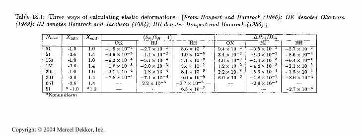
The results obtained from Houpert and Hamrock (1986) are compared inTable 18.1 with results obtained by Hamrock and Jacobson (1984) as well as
Copyright © 2004 Marcel Dekker, Inc.
458 FUNDAMENTALS OF FLUID FILM LUBRICATION
by Okamura (1982), who used simpler approaches than that used by Houpertand Hamrock (1986). Hamrock and Jacobson (1984) assumed the pressure tobe constant in the interval pQ — AX/2, Xj + AX/2] and used an analyticalexpression for the integral of ln(Xj — X'). Okamura (1982) did not use anyanalytical solutions and assumed simply that
A X;-X,
X,-X, (18.31)
where A = X;+i — X;. The three approaches can be compared by assuming aHertzian pressure. Between X = — 1 and X = 1 the film shape while assuminga Hertzian pressure should be flat, leading to AR = 0, where AR is denned as
AR=^-+J-J^ (18.32)
and <5,7t is the dimensionless maximum deformation. This can be compared withthe value of <$# obtained by analytic integration of Eq. (18.26) with a Hertzianpressure distribution
1 !n(2) + 0.25 (18.33)2
The largest value AR^/R^ of AR/R^ is found at X = —1 and X = 1 (becauseof the slope discontinuity) and is shown in Table 18.1 with the correspondingvalue of J / R — 1. The film thickness R^ where dP/efX = 0 has been chosento be equal to 0.5; X in and X ax define the first and last values of X and^Vmax is the number of nodes.
Table 18.1 shows that for a given mesh the best accuracy in calculating Jand AR,?, is obtained by using the Houpert and Hamrock (1986) approach. Thevalue of J t from Hamrock and Jacobson (1984) is in some cases less accuratethan that from Okamura (1982) because they did not separate the constant aswas done in Eq. (18.23). But <5, is not really significant, since any inaccuracyin its calculation can be compensated for by Ro in the film thickness equation.The important parameter of Table 18.1 is AR^, since it is a measure of theflatness of the Rim. This aspect is extremely important at high loads, wherethe elastic deformations are two or three orders of magnitude larger than thefilm thickness.
Also shown in Table 18.1 are the results obtained with a uniform mesh of661 nodes by Hamrock and Jacobson (1984). Extremely small values of AR^were calculated and cannot be reproduced with the new approach because ofstorage problems with the matrix D,, and because a large system of equationswould have to be solved with such a mesh. By using a nonuniform mesh with afine grid near X = — 1 and X = 1 , similar results were found with a small valueof %nax ( Vmnx = 51) as indicated in Table 18.1. The latter case illustrates thepower of the approach developed by Houpert and Hamrock (1986).
Copyright © 2004 Marcel Dekker, Inc.
ELASTIC DEFORMATION
459
§-§
& e
g^
oo3)
^!H<1<-0
**e^^g'a><*s^
mM-iOnBx:o
1 1
! t
1 !
1o o o o o o o
X X X X X X
X
r-i oo K5 c*i ci oo c
! !
1 i
! !
!
! 1
1 1
! 1
!O CD O O O O O
X X x X X X X
to ( -f
y to oq tD^
r-i f-i t<
t-i triI
! I
! !
! I
1 )
1 !
1 !
O CD O O CD O
^ w w
rH
, i
X X X X X X ' '
f CD
C) C
< CDo a? -
w c) to
^-onor-mcofj.
OCDOCDOO^CD
xxxxxx^x
tDCDW^r-HCD^tn
!
I 7 7 7 7 i ?CD
CD O CD CD CD
!
X X X X X X
t- w 0 00
c- w
tn c-l t -
! 1
1 !
1 1
^ M
-]-
M
-q* -t
! 1
1 !
1 i
0 CD 0 0 O CD
X X X X X X
}
C en f3 to w
oq
1^1
1 1*
1 1
q^p^fO^f-^P
CDSDCDtOCDtCtp^
^sSSg^g^
Copyright © 2004 Marcel Dekker, Inc.
460 FUNDAMENTALS OF FLUID FILM LUBRICATION
The solution of Eqs. (18.17), (18.20), and (18.26) needs to be evaluatednumerically.
18.4 Compressible Solution
Considering compressibility effects while neglecting side leakage and assumingtime- invariant conditions allows the appropriate form of the Reynolds equationto be written from Eq. (7.51) as
dp
The equation is the integrated form of the Reynolds equation, and Pm^m is thecorresponding value of p/t when dp/da; = 0. This section is extensively based onthe paper of Houpert and Hamrock (1986). The analysis is presented in detailin that paper and summarized here. Letting
Pop ?y = %}7? (18.34)
and using Eq. (18.7) gives Eq. (7.51) as
^ (18.35)
where A* is the same constant developed in Eq. (18.9).The basic equation that will solve for the pressure at each node within a
lubricated conjunction is
Pi(is.36)
The expression for the film shape can be obtained by using the results of theprevious section, and the expressions for the dimensionless density and viscositycan be expressed from equations developed in Chapter 4 as
X^ ^Fr.i = R,,o + + E -i (18.37)
j'=l
_ 0.6 x 101 + 1.7* lO-
exp {[m(??o) + 9.67] [-1 + (l + 5.1 x 10" . ) ] j (4.10)
Note in Eq. (18.37) that Rr,o contains the constant term - lintroduced in Eq. (18.30). Furthermore, the density expression given in Eq.(4.19) was obtained from Dowson and Higginson (1966), and the viscosity ex-pression given in Eq. (4.10) from Roelands (1966). Also note that in Eqs. (4.19)
Copyright © 2004 Marcel Dekker, Inc.
COMPRESSIBLE SOLUTION 461
and (4.10) metric units are to be used. Values of fluid properties given as Ziand 7/0 in Eq- (4-10) may be obtained directly from Chapter 4 for the particularfluid being investigated. Observe from these equations that coupling the elas-ticity and rheology equations into the integrated form of the Reynolds equationproves to be a difficult task mainly for the following reasons:
1. The lubricant viscosity changes by several orders of magnitude as thelubricant travels through the conjunction (f; can be 10 in the contactcenter and 1 at the inlet and outlet).
2. The elastic deformation of the solid surfaces can be several orders largerthan the minimum film thickness (<5/h.min can be ItF or 10**).
For both these reasons extremely accurate numerical methods are required toget successful convergence of the problem.
Once the pressure is obtained, the dimensionless normal load per unit widthcan be evaluated from the following equation:
--rMaking use of Eqs. (18.7) and (18.34) in dimensionless terms reduces this equa-tion to
/ ""* dX = - (18.38)
The unknowns in this problem are
r,end outlet meniscusN number of nodes used.%. o constant
;Om_Hr,m value of /9,%. where dj- / Xr = 07- -j pressure at node j (j = 2, N)
The boundary conditions are
1. -F . = 0 for Xr = X,.,min.
2. R. = dR./dZ, = 0 for X, = X,,
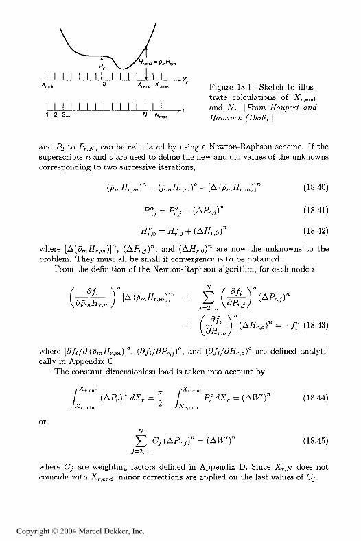
Figure 18.1 more clearly identifies Xr.end and #. Note that X,.,jv is the nearestnode to Xr.end such that .Xr.jv < r.cnd A second-degree curve for F(X) canbe defined by using #jv-i, -H W) and .Hjv+i, and then Xend can be calculatedsuch that
Rr(Rr,cnd) = r, (18.39)
Appendix B gives the corrections to be applied to weighting factors due to X,..Having defined Xr.end and JV, the remaining TV + 1 unknowns, pmRr.mt Rr,o<
Copyright © 2004 Marcel Dekker, Inc.
462 FUNDAMENTALS OF FLUID FILM LUBRICATION
! I I I I I H! I I I I li I I^min ^ r.end ;mi
I I ! I I I I I ! I I ! I I I
Figure 18.1: Sketch to illus-trate calculations of endand JV. [From Rot/per
and Pa to Pr , can be calculated by using a Newton-Raphson scheme. If thesuperscripts n and o are used to define the new and old values of the unknownscorresponding to two successive iterations,
(/ iRr.rn)" = ( rnRr,m)° + [A ( mRr.m)]" (18.40)
l" (18.41)
)" (18.42)
where [A(/9rnRr,nt)]*\ (AP-j)", and (AR,-,o)" are now the unknowns to theproblem. They must all be small if convergence is to be obtained.
From the definition of the Newton-Raphson algorithm, for each node t
a/,Rr,t
+
(AR,,.)" = -/° (18.43)
where [d /d(/9 Rr,!n)]°, (d/i/dPr,j)°, and ((%/<9R,.,o)° are defined analyti-cally in Appendix C.
The constant dimensionless load is taken into account by
(AP,)" dX, = - P; dX, = (AtV)" (18.44)
or
^ , "'p. (An,y
^ 7X n,)n
)f
j)" = (AtV (18.45)
where C are weighting factors defined in Appendix D. Since X?.,Ar does notcoincide with ,Xr,end; minor corrections are appHed on the last values of (L.
Copyright © 2004 Marcel Dekker, Inc.
FLOW, LOADS AND CENTER OF PRESSURE 463
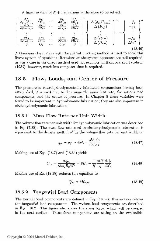
A linear system of V + 1 equations is therefore to be solved.
o r? (7 o ^ -n r.oj j ^AW(18.46)
A Gaussian elimination with the partial pivoting method is used to solve thislinear system of equations. Iterations on the system approach are still required,as was a case in the direct method used, for example, in Hamrock and Jacobson(1984); however, much less computer time is required.
18.5 Flow, Loads, and Center of Pressure
The pressure in elastohydrodynamically lubricated conjunctions having beenestablished, it is used here to determine the mass How rate, the various loadcomponents, and the center of pressure. In Chapter 8 these variables werefound to be important in hydrodynamic lubrication; they are also important inelastohydrodynamic lubrication.
18.5.1 Mass Flow Rate per Unit Width
The volume Row rate per unit width for hydrodynamic lubrication was describedin Eq. (7.38). The mass How rate used in elastohydrodynamic lubrication isequivalent to the density multiplied by the volume How rate per unit width or
(18.47)9m=/9<? =
Making use of Eqs. (18.7) and (18.34) yields
_ ^7?
Making use of Eq. (18.35) reduces this equation to
(18.49)
18.5.2 Tangential Load Components
The normal load components are defined in Eq. (18.38); this section deHnesthe tangential load components. The various load components are describedin Fig. 18.2. This figure also shows the shear force, which will be coveredin the next section. These force components are acting on the two solids.
Copyright © 2004 Marcel Dekker, Inc.
464 FUNDAMENTALS OF FLUID FILM LUBRICATION
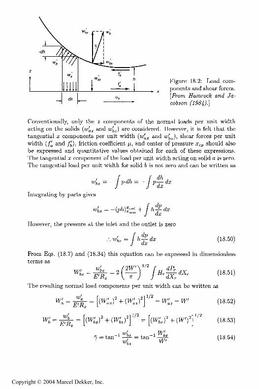
Figure 18.2: Load com-ponents and shear forces,
and Jat-
Conventionally, only the components of the normal toads per unit widthacting on the solids (w z and w ) are considered. However, it is felt that thetangential a: components per unit width (w and u* ), shear forces per unitwidth (/Q and / ), friction coefficient t, and center of pressure a p should alsobe expressed and quantitative values obtained for each of these expressions.The tangential 2 component of the load per unit width acting on solid a is zero.The tangential toad per unit width for solid 6 is not zero and can be written as
/* ,, f 5x = * / P^ = - / Pj- <
Integrating by parts gives
However, the pressure at the inlet and the outlet is zero
(18.50)
From Eqs. (18.7) and (18.34) this equation can be expressed in dimensiontessterms as
The resulting normal bad components per unit width can be written as
,,/ r i oi 1/2tV' = " = (W' r + fM ' ) = tV' = IV'" E'Ar L^ "" ^ " ^ J "
- j —i T = tan —
+
(18.52)
(18.53)
(18.54)
Copyright © 2004 Marcel Dekker, Inc.
FLOW, LOADS AND CENTER OF PRESSURE 465
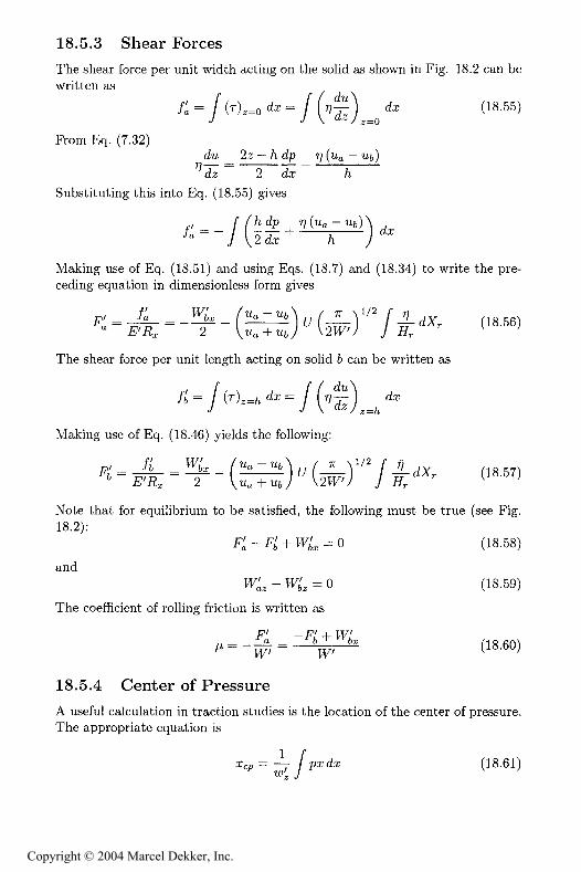
18.5.3 Shear Forces
The shear force per unit width acting on the solid as shown in Fig. 18.2 can bewritten as
&r (18.55)y y \ <M:/2=o
From Eq. (7.32)dM 22 — /t t%p 7? (Ma — Mb)
&J " "*2 ^
Substituting this into Eq. (18.55) gives
Making use of Eq. (18.51) and using Eqs. (18.7) and (18.34) to write the pre-ceding equation in dimensionless form gives
7?' _ Jo _ "hT
F'7? 7
The shear force per unit length acting on solid & can be written as
Making use of Eq. (18.46) yields the following:
Note that for equilibrium to be satisfied, the following must be true (see Fig.18.2):
F - F + = 0 (18.58)
andWL - W , = 0 (18.59)
The coefficient of rolling friction is written as
18.5.4 Center of Pressure
A useful calculation in traction studies is the location of the center of pressure.The appropriate equation is
= — /pxda: (18.61)
Copyright © 2004 Marcel Dekker, Inc.
466 FUNDAMENTALS OF FLUID FILM LUBRICATION
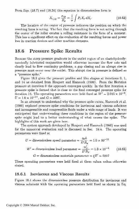
From Eqs. (18.7) and (18.34) this equation in dimensionless form is7* 1 /*
The location of the center of pressure indicates the position on which theresulting force is acting. The fact that the resulting force is not acting throughthe center of the roller creates a rolling resistance in the form of a moment.This has a significant effect on the evaluation of the resulting forces and powerloss in traction devices and other machine elements.
18.6 Pressure Spike Results
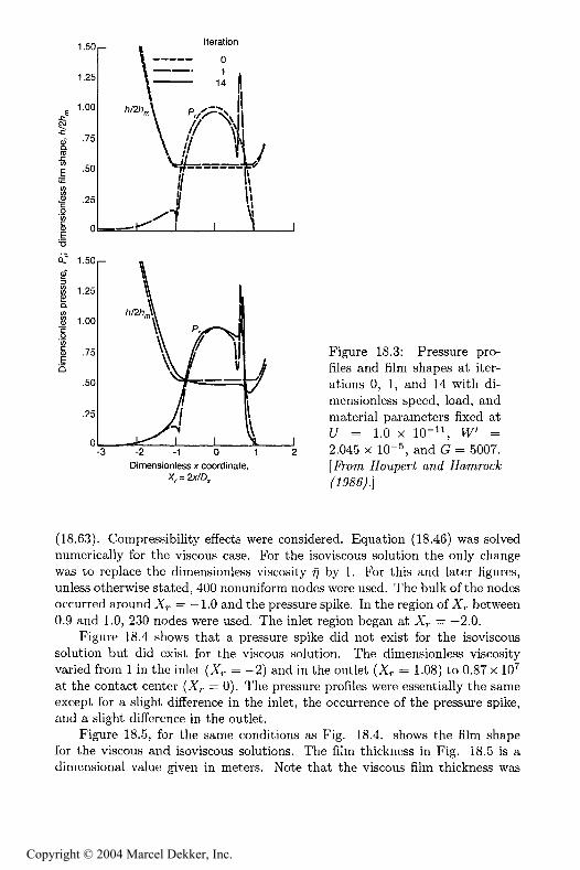
Because the steep pressure gradients in the outlet region of an elastohydrody-namically lubricated conjunction would otherwise increase the flow rate andclearly lead to flow continuity problems, a gap closing and an abrupt rise inpressure must occur near the outlet. This abrupt rise in pressure is defined asa "pressure spike."
Figure 18.3 gives the pressure profiles and film shapes at iterations 0, 1,and 14 as obtained from Houpert and Hamrock (1986). From the Hertzianpressure at iteration 0 the approach converges quickly. In the first iteration apressure spike is formed that is close to the final converged pressure spike foriteration 14. The operating parameters were held fixed at tV = 2.045 x 10" ,!7 = 1.0 x 10-", and C = 5007.
In an attempt to understand why the pressure spike exists, Hamrock et al.(1988) explored pressure spike conditions for isoviscous and viscous solutionsand incompressible and compressible fluids under a wide range of loads. It wasanticipated that understanding these conditions in the region of the pressurespike might lead to a better understanding of what causes the spike. Thehighlights of this work are given here.
The system approach developed by Houpert and Hamrock (1986) was usedfor the numerical evaluation and is discussed in Sec. 18.4. The operatingparameters were fixed at
t/ = dimensionless speed parameter = = 1.0 x 10".E'-Rzu/
IV' = dimensionless load parameter = —-j=— = 1.3 x 10*4 (ig.63).& Ax
C = dimensionless materials parameter = $E' = 5007
These operating parameters were held fixed at these values unless otherwisestated.
18.6.1 Isoviscous and Viscous Results
Figure 18.4 shows the dimensionless pressure distribution for isoviscous andviscous solutions with the operating parameters held fixed as shown in Eq.
Copyright © 2004 Marcel Dekker, Inc.
PRESSURE SPIKE RESULTS 467
1.50
1.25
1.00
.75
.50
.25
0
1.50
1.25
1.00
.75
.50
.25
0
Iteration
-3
/i/2/i,
- 2 - 1 0 1Dimensionless x coordinate,
Figure 18.3: Pressure pro-files and Him shapes at iter-ations 0, 1, and 14 with di-mensionless speed, load, andmaterial parameters fixed at!7 = 1.0 x 10-", IV' =2.045 x 10*5,
(18.63). Compressibility effects were considered. Equation (18.46) was solvednumerically for the viscous case. For the isoviscous solution the only changewas to replace the dimensionless viscosity by 1. For this and later figures,unless otherwise stated, 400 nonuniform nodes were used. The bulk of the nodesoccurred around X,. = —1.0 and the pressure spike. In the region of X between0.9 and 1.0, 230 nodes were used. The inlet region began at X = —2.0.
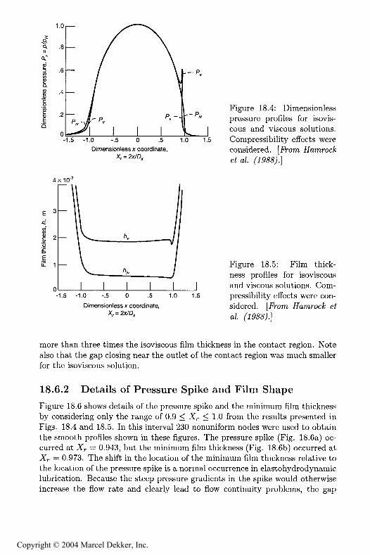
Figure 18.4 shows that a pressure spike did not exist for the isoviscoussolution but did exist for the viscous solution. The dimensionless viscosityvaried from 1 in the inlet (Xr = -2) and in the outlet (X = 1.08) to 0.87 x 10?at the contact center (X = 0). The pressure profiles were essentially the sameexcept for a slight difference in the inlet, the occurrence of the pressure spike,and a slight difference in the outlet.
Figure 18.5, for the same conditions as Fig. 18.4. shows the film shapefor the viscous and isoviscous solutions. The film thickness in Fig. 18.5 is adimensional value given in meters. Note that the viscous film thickness was
Copyright © 2004 Marcel Dekker, Inc.
468 FUNDAMENTALS OF FLUID FILM LUBRICATION
Q.I!o.--
§ .6-
-1.5 -1.0 -.5 0 .5 1.0 1.5Dimensionless x coordinate,
Xr = 2x/D,
4x10*7
-1.5 -1.0 -.5 0 .5 1.0
Dimensionless x coordinate,
1.5
Figure 18.4: Dimensionlesspressure profiles for isovis-cous and viscous solutions.Compressibility effects wereconsidered, "o
Figure 18.5: Film thick-ness profiles for isoviscousand viscous solutions. Com-pressibility effects were con-sidered. [Fh)m RamrocA* e^a/.
more than three times the isoviscous film thickness in the contact region. Notealso that the gap closing near the outlet of the contact region was much smallerfor the isoviscous solution.
18.6.2 Details of Pressure Spike and Film Shape
Figure 18.6 shows details of the pressure spike and the minimum film thicknessby considering only the range of 0.9 < X,. < 1.0 from the results presented inFigs. 18.4 and 18.5. In this interval 230 nonuniform nodes were used to obtainthe smooth profiles shown in these figures. The pressure spike (Fig. 18.6a) oc-curred at Xr = 0.943, but the minimum film thickness (Fig. 18.6b) occurred atXr *= 0.973. The shift in the location of the minimum film thickness relative tothe location of the pressure spike is a normal occurrence in elastohydrodynamiclubrication. Because the steep pressure gradients in the spike would otherwiseincrease the How rate and clearly lead to flow continuity problems, the gap
Copyright © 2004 Marcel Dekker, Inc.

PRESSURE SPIKE RESULTS 469
.81—
.92 .94 .96 .98Dimensionleas x coordinate,
1.00
Figure 18.6: Pressure andRim thickness profiles in re-gion 0.9 < X,. < 1.0.(a) Dimensionless pressure;(b) dimensionless film thick-ness. .B-om Ratmroc^ ei a/.
must he ciosed near the outlet end of the contact as shown in Fig. 18.6b. Thesmoothness of the pressure spike in Fig. 18.6a indicates a sufficient number ofnodes in the spike region.
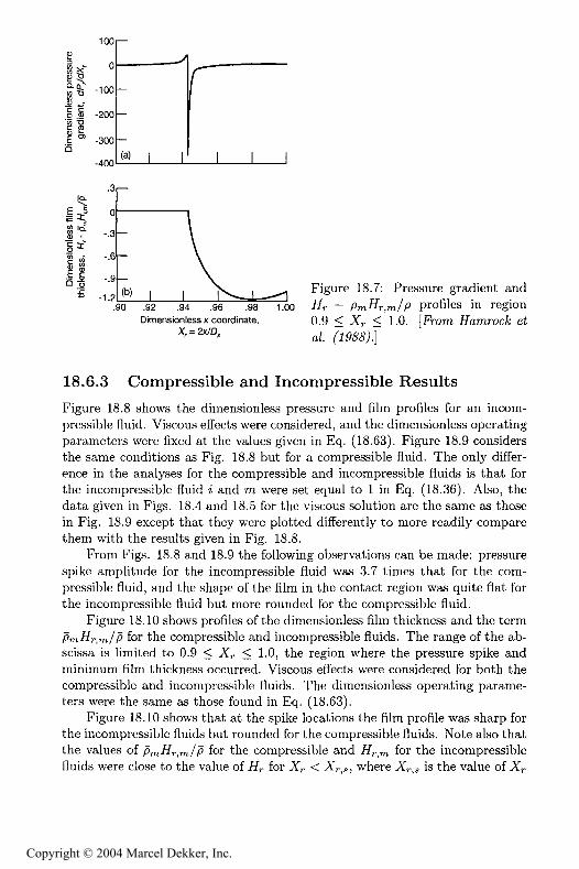
Figure 18.7 shows the variation of the dimensionless pressure gradient&F ./o!Xr in the region 0.9 < X,- < 1.0. The pressure gradient changed drasti-cally at the spike location. Figure 18.7b shows the variation of .%. — p r m/Pin the region 0.9 < Xr < 1.0. Recall that the expression .%. — pmRr,m/<o occursin the integrated form of the Reynolds equation given in Eq. (18.36) as doesthe pressure gradient plotted in Fig. 18.7a. The value of ,%. — Pm#r,m/p wasnear zero until the pressure spike and then varied considerably afterward. Inrelating oLF / Xr and ,%. — p Fr, //? as they appear in Fig. 18.7 with Eq.(18.36), it should be pointed out that varied from 1 in the inlet (Xr = —2)to 0.87 x 10 at the contact center (Xr = 0) to 0.55 x 10 at the pressure spikelocation (X,- = 0.943) to 1 at the outlet (X,. = 1.08).
Similar conclusions were drawn for a large range of dimensionless loads,namely, that the pressure spike did not occur for the isoviscous solutions butdid occur for the viscous solutions. Also, the viscous film shape for a targe loadrange shows a gap closing near the outlet, whereas the isoviscous film resultshad either a slight gap closing or none at all.
Copyright © 2004 Marcel Dekker, Inc.
470 FUNDAMENTALS OF FLUID FILM LUBRICATION
100
-100
-200
-300
^
—
-
—(a) I I
/"
I I !
at
0
-.3
-.6
-.9
- -1.2 M I.90 .92 .94 .96 .98
Dimensionless x coordinate,X, = 2x/D,
1.00
Figure 18.7: Pressure gradient andH,. - /9m#r,m/P profiles in region0.9 < Xr < 1.0. [From FamrocA: et
18.6.3 Compressible and Incompressible Results
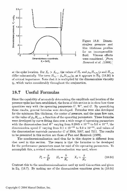
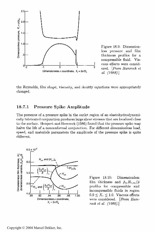
Figure 18.8 shows the dimensionless pressure and film profiles for an incom-pressible fluid. Viscous effects were considered, and the dimensionless operatingparameters were fixed at the values given in Eq. (18.63). Figure 18.9 considersthe same conditions as Fig. 18.8 but for a compressible fluid. The only differ-ence in the analyses for the compressible and incompressible fluids is that forthe incompressible fluid ^ and rn were set equal to 1 in Eq. (18.36). Also, thedata given in Figs. 18.4 and 18.5 for the viscous solution are the same as thosein Fig. 18.9 except that they were plotted differently to more readily comparethem with the results given in Fig. 18.8.
From Figs. 18.8 and 18.9 the following observations can be made: pressurespike amplitude for the incompressible fluid was 3.7 times that for the com-pressible Huid, and the shape of the film in the contact region was quite flat forthe incompressible fluid but more rounded for the compressible Huid.
Figure 18.10 shows profiles of the dimensionless film thickness and the termpm-%-,m//3 for the compressible and incompressible Huids. The range of the ab-scissa is limited to 0.9 < .Xr < 1.0, the region where the pressure spike andminimum film thickness occurred. Viscous effects were considered for both thecompressible and incompressible Huids. The dimensionless operating parame-ters were the same as those found in Eq. (18.63).
Figure 18.10 shows that at the spike locations the film proAle was sharp forthe incompressible fluids but rounded for the compressible fluids. Note also thatthe values of /9 -%-,rn/P for the compressible and F,.,Tn for the incompressiblefluids were close to the value of,%. for X < Xr,s, where X,-,s is the value of Xr
Copyright © 2004 Marcel Dekker, Inc.
USEFUL FORMULAS 471
2.5
2.0
1.0
"-2 -1 0 1Dimensionless x coordinate,
X, = 2x/D
Figure 18.8: Dimen-sionless pressure andRim thickness profilesfor an incompressiblefluid. Viscous effectswere considered. [From
; e? a/.
at the spike location. For > r s; the values of .%- and pmFr,m/ ,differ substantially. The term 77 : * m^rm/Pi s it appears in Eq. (18.36) isof critical importance. Note that it is multiplied by the dimensionless viscosityf , which varies considerably throughout the conjunction.
18.7 Useful Formulas
Since the capability of accurately determining the amplitude and location of thepressure spike has been established, the focus of this section is to show how thesequantities vary with the operating parameters Lf, PV', and (?. By quantifyingthese results, general formulas were developed. Formulas were also developedfor the minimum film thickness, the center of pressure, and the mass flow rate,or the value of/9m#e,m; function of the operating parameters. These formulaswere developed by curve fitting data over a wide range of operating parameterswith the dimensionless load tV' varying from 0.2045 x 10* to 5.0 x 10" , thedimensionless speed t/ varying from 0.1 x 10" to 5.0 x 10" , and values ofthe dimensionless materials parameter G of 2504, 5007, and 7511. The resultsto be presented in this section are those of Pan and Hamrock (1989).
The nondimensionalization used thus far in this chapter is different fromthat used in this section. The reason is that the formulas to be developedfor the performance parameters must be void of the operating parameters. Toaccomplish this, a revised nondimensionalization was used, where
P, = - 7 ^ = *5" ' = 7T ('
Contrast this to the nondimensionalization used up until this section and givenin Eq. (18.7). By making use of the dimensionless equations given in (18.64)
Copyright © 2004 Marcel Dekker, Inc.
472 FUNDAMENTALS OF FLUID FILM LUBRICATION
2.5
§1.5
JH
§1.0
-1 0 1Dimensionless x coordinate, X, = 2x/D,
Figure 18.9: Dimension-less pressure and Rimthickness profiles for acompressible fluid. Vis-cous effects were consid-ered,a/,
the Reynolds, film shape, viscosity, and density equations were appropriatelychanged.
18.7.1 Pressure Spike Amplitude
The presence of a pressure spike in the outlet region of an elastohydrodynami-cally lubricated conjunction produces large shear stresses that are localized closeto the surface. Houpert and Hamrock (1986) found that the pressure spike mayhalve the life of a nonconformal conjunction. For different dimensionless load,speed, and materials parameters the amplitude of the pressure spike is quitedifferent.
6.5x10
.90 .92 .94 .96 .98 1.00Dimensionless x coordinate,
X,= 2x/D,
Figure 18.10: Dimensionlessfilm thickness and 7 ^ m/pprofiles for compressible andincompressible fluids in region0.9 < X,. < 1.0. Viscous effectswere considered. [FS"om
t a?.
Copyright © 2004 Marcel Dekker, Inc.
USEFUL FORMULAS 473
1.00x10*2
Dimensionlessload,-V'
50x10'"
-.02 0Dimensionless x coordinate, X. = x / R.
.02 .04
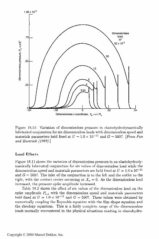
Figure 18.11: Variation of dimensionless pressure in elastohydrodynamicallylubricated conjunction for six dimensionless loads with dimensionless speed andmaterials parameters held fixed at f/ = 1.0 x 10*"" and (2 = 5007. [Fhim
Load Effects
Figure 18.11 shows the variation of dimensionless pressure in an elastohydrody-namically lubricated conjunction for six values of dimensionless load while thedimensionless speed and materials parameters are held fixed at f/ = 1.0 x 10"*"and G = 5007. The inlet of the conjunction is to the left and the outlet to theright, with the contact center occurring at X^ = 0. As the dimensionless loadincreased, the pressure spike amplitude increased.
Table 18.2 shows the effect of six values of the dimensionless load on thespike amplitude F ^ with the dimensiontess speed and materials parametersheld fixed at t/ = 1.0 x 10*" and G = 5007. These values were obtained bynumerically coupling the Reynolds equation with the film shape equation andthe rheology equations. This is a fairly complete range of the dimensionlessloads normaHy encountered in the physical situations existing in elastohydro-
Copyright © 2004 Marcel Dekker, Inc.
474 FUNDAMENTALS OF FLUID FILM LUBRICATION
.5x10*2
-r .3
Dimensionlessspeed,U
50x10'^
-.02 0Dimensionless x coordinate, X, =
.02J.04
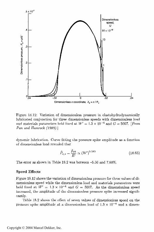
Figure 18.12: Variation of dimensionless pressure in elastohydrodynamicallylubricated conjunction for three dimensionless speeds with dimensionless loadand materials parameters held Axed at tV = 1.3 x 10"** and C = 5007. [.fromPan, ana* #amroc%;
dynamic lubrication. Curve fitting the pressure spike amplitude as a functionof dimensiontess load revealed that
=< (18.65)
The error as shown in Table 18.2 was between -5.56 and 7.
Speed Effects
Figure 18.12 shows the variation of dimensionless pressure for three values of di-mensionless speed while the dimensionless load and materials parameters wereheld fixed at IV' = 1.3 x 10*" and G = 5007. As the dimensionless speedincreased, the amplitude of the dimensionless pressure spike increased signifi-cantly.
Table 18.2 shows the effect of seven values of dimensionless speed on thepressure spike amplitude at a dimensionless load of 1.3 x 10"** and a dimen-
Copyright © 2004 Marcel Dekker, Inc.
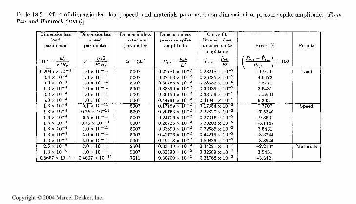
Table 18.2: Effect of dimensionless toad, speed, and materials parameters on dimensionless pressure spike amplitude. [From
[**
o
Dimensiontess
]oad
parameter
iv "E' ,
0.2045 x 10*40.4 x 10-"0.6 x 10-41.3 x 10"43.0 x 10-45.0 x 10*41.3 x 10-41.3 x 10*41.3 x 10*41.3 x 10-41.3 x 10*41.3 x 10'41.3 x 10*42.6 x 10""1.3 x 10*4
0.8667 x 10⁻⁴
Dimensionlessspeed
parameter
*?°"E'Ac
1.0 x 10-"1.0 x 10*"1.0 x 10*"1.0 x 10""1.0 x 10""1.0 x 10""0.1 x 10""0.25 x 10""0.5 x 10*"0.75 x 10""1.0 x 10""3.0 x 10""5.0 x 10""2.0 x 10""1.0 x 10""
0.6667 x 10""
Dimensionlessmaterials
parameter
G f E'
5007500750075007500750075007500750075007500750075007250450077511
Dimensionless
pressure spikeamplitude
r, P
''' E'
0.22781 x 10"0.27653 x 10*20.30755 x 10-20.33890 x 10"20.36150 x 10*20.44791 x 10"20.17489 x 10"-"0.20763 x 10"20.24706 x 10*20.28725 x 10-20.33890 x 10*20.42776 x 10-20.49218 x 10-20.33549 x 10"0.33890 x 10*20.30760 x 10"2
Curve-fitdimensionless
pressure spike
amplitude
B Pst''' E'
0.23218 x 10'0.26285 x 10 20.28332 x 10-20.32689 x 10-20.38159 x 10-20.41941 x 10-20.17354 x IQ--'0.22327 x 10-20.27016 x 10-20.30203 x 10-20.32689 x 10-20.44219 x 10-20.50889 x 10-20.34291 x 10--=0.32689 x 10-20.31788 x 10-2
Error, %
/P.,s-&s\
^ ,s J "-1.91614.94737.87713.5431-5.55646.36370.7707-7.5346-9.3501-5.14453.5431-3.3744-3.3946-2.21073.5431-3.3421
Results
Load
Speed
Materials
Copyright © 2004 Marcel Dekker, Inc.
476 FUNDAMENTALS OF FLUID FILM LUBRICATION
sionless materials parameter of 5007. For the seven sets of data a curve fit wasapplied that resulted in
A,, = o< y°'2?5 (18.66)
The error as it related to the speed data was between -9.35 and 3.54 percent.
Materials Effects
A study of the influence of the dimensionless materials parameter O on thepressure spike amplitude has to be approached with caution, since in practiceit is not possible to change the physical properties of the materials, and hencethe value of G, without influencing the other operating parameters (Z7 andW). The results obtained from calculations performed for three values of thedimensionless materials parameter are shown in Table 18.2. The general form ofthese results, showing how the spike amplitude is a function of the dimensionlessmaterials parameter, is written as
(18.67)
where
(18.68)^ ^
By applying a least-squares power fit to the three pairs of data
A,3 = - 7 <x G°'3 (18.69)
The proportionality equations (18.65), (18.66), and (18.69) have establishedhow the pressure spike amplitude varies with the load, speed, and materialsparameters, respectively. This enables a composite pressure spike amplitude tobe expressed as
Pe_s = y = 0.648 (tV')
It is evident that the materials parameter has the largest effect on the pressurespike amplitude, followed by speed and load.
18.7.2 Pressure Spike Location
As shown in Fig. 18.11, as the dimensionless load increased, the dimensionlesspressure spike location Jfe,s moved toward the outlet. These results are quan-tified in Table 18.3 for six dimensionless loads with the speed and materialsparameters held fixed at t/ = 1.0 x 10*" and C = 5007. From Fig. 18.12,the location of the pressure spike also moved toward the outlet as the speedwas decreased. These results are also quantified in Table 18.3. Also shown inTable 18.3 are results for three materials parameters. Making use of the data
Copyright © 2004 Marcel Dekker, Inc.
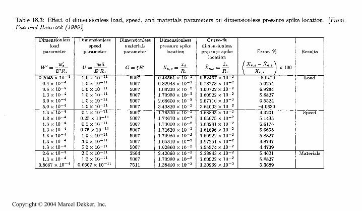
Table 18.3: Effect of dimensionless load, speed, and materials parameters on dimensionless pressure spike location. [FromPaw and FamwcA;
O?3c;
Dimensionlessload
parameter
IV ^
0.2045 x 10-40.4 x 10-40.6 x 10-41.3 x 10-43.0 x 10-45.0 x 10-41.3x 10-41.3 x 10-41.3 x 10"41.3 x 10-41.3 x 10-41.3 x 10-41.3 x 10-42.6 x 10-41.3 x 10-4
0.8667 x 10⁻⁴
Dimensionlessspeed
parameter
E'Rx1.0 x 10-"1.0 x 10-"1.0 x 10-"1.0 x 10-"1.0 x 10-"1.0 x 10-"0.1 x 10-"0.25 x 10""0.5 x 1Q-"0.75 x 10-"1.0 x 10-"3.0 x 10-"5.0 x 10-"2.0 x 10-"1.0 x 1Q-"
0.6667 x 10-"
Dimensionlessmaterialsparameter
( ^EVt-T S *
5007500750075007500750075007500750075007500750075007250450077511
Dimensionlesspressure spike
location
^ Is
°'' Rx
0.48561 x 10-"0.82948 x 10*21.08220 x 10*21.70980 x 10"22.68600 x 10-23.49820 x 10-21.76520 x 10""1.74670 x 10-21.73000 x 10-21.71620 x 10"21.70980 x 10-21.65310 x 10-21.62860 x 1Q-22.42060 x 10*"1.70980 x 10-21.38400 x 10-2
Curve-Htdimensionlesspressure spike
location
''" Rx
0.52467 x 10-"0.78778 x 10-21.00722 x 10-21.60922 x 10-22.67116 x 10-23.64033 x 10-21.68895 x 10-"1.65675 x 10-21.63281 x 10-21.61896 x 10*21.60922 x 10-21.57251 x 10-21.55574 x 10-22.28843 x 10-"1.60922 x 10-21.30969 x 10-2
Error, %
\ X.,s / *
-8.04295.02546.92845.88270.5524-4.06304.32015.14955.61785.66555.88274.87474.47395.46015.88275.3689
Results
Load
Speed
Materials
Copyright © 2004 Marcel Dekker, Inc.
478 FUNDAMENTALS OF FLUID FILM LUBRICATION
in Table 18.3 by following the procedure used in the previous section allows anequation for the dimensionless pressure spike location to be written in terms ofthe operating parameters as
X = A = l.Hl (1V')°-606 -0.021 0.077 ^g )
AxThis equation shows the spike location to he highly affected by the dimension-less load but only slightly affected by the dimensionless speed and materialsparameters. Knowing the location of the pressure spike in terms of the operat-ing parameters is extremely valuable in setting up a nodal structure that willproduce convergent results. The percentage of error (Table 18.3) was between-8.04 and 6.93%.
18.7.3 Minimum and Central Film Thicknesses
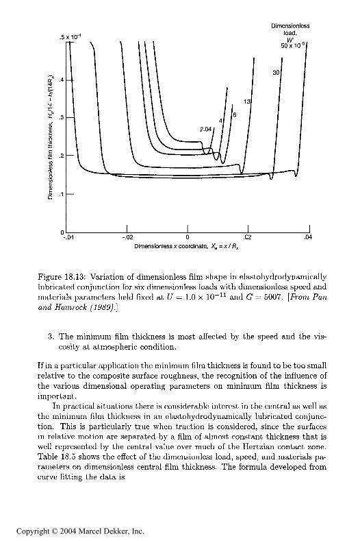
Figure 18.13 shows the effect of dimensionless load on film shape for exactlythe same conditions as presented in Fig. 18.11. The dimensionless speed andmaterials parameters were held fixed at <!7 = 1.0 x 10" and C = 5007. Fig-ure 18.13 shows that the minimum Rim thickness decreased as the load wasincreased except for the highest load. The discrepancy of the highest-load casefrom the other results is not understood. As shown in Fig. 18.13 the locationof the minimum Him thickness moved considerably toward the outlet as thedimensionless load was increased.
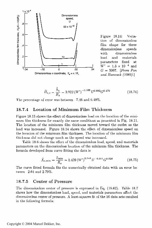
Figure 18.14 shows the variation of dimensionless Him shape for three di-mensionless speed parameters with the dimensionless load and materials pa-rameters held fixed at W" = 1.3 x 10 and G = 5007. The minimum Himthickness decreased significantly as the dimensionless speed decreased.
Table 18.4 shows the effect of the dimensionless load, speed, and materialsparameters on dimensionless minimum Rim thickness. The formula developedfrom curve Rtting the 16 groups of data is
R^ = = 1.714 (t')-°'S 0.694 0.568 (lg 72)
This curve Rt formula Rts the numerical data within -7.72 and 6.69%.By making use of Eqs. (18.10), (18.11), and (18.14), Eq. (18.72) can be
expressed in dimensional form as
in = L806 (t4)-' M°' -568R0.434 (18.73)
Three things should be noted from Eq. (18.73):
1. The minimum Rim thickness is independent of the effective modulus ofelasticity.
2. The minimum Rim thickness is only slightly dependent on the normalapplied load.
Copyright © 2004 Marcel Dekker, Inc.
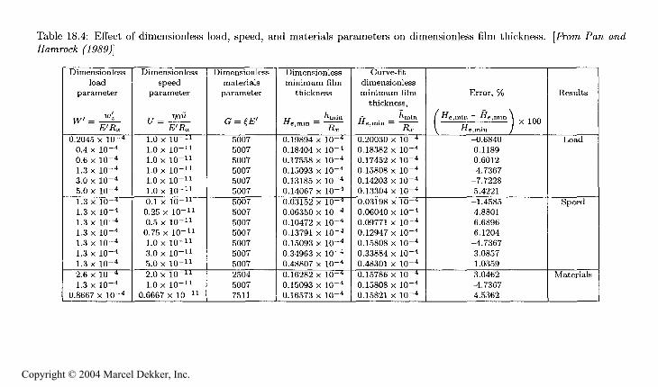
Table 18.4: Effect of dimensionless load, speed, and materials parameters on dimensionless film thickness. [From Paw
G
Dimensiontessload
parameter
tV *"E'Rx
0.2045 x 10-40.4 x 10-40.6 x 10-41.3 x 10-43.0 x 1Q-45.0 x 1Q-41.3 x 10-41.3x 10-41.3 x 10-41.3 x 10-41.3 x 10-41.3 x 10-41.3 x 10-42.6 x 10-41.3 x 10⁻⁴
0.8667 x 10"4
Dimensiontessspeed
parameter
y 770"E'R..
1.0 x 10-"1.0 x 10-"1.0 x 10-"1.0 x 10-"1.0 x 10-"1.0 x 10-"0.1 x 10-"0.25 x 10-"0.5 x 10-"0.75 x 10-"1.0 x 10-"3.0 x 10-"5.0 x 10-"2.0 x 10-"1.0 x 1Q-"
0.6667 x 10-"
Dimensiontessmaterialsparameter
<? R'
5007500750075007500750075007500750075007500750075007250450077511
Dimensionlessminimum film
thickness
A^ . "mm
Ra:
0.19894 x 10-40.18404 x 10-40.17558 x 10-40.15093 x 10-40.13185 x 10-40.14067 x 10-40.03152 x 10-40.06350 x 10-40.10472 x 10"40.13791 x 10*40.15093 x 10-40.34963 x 1Q-40.48807 x 10-40.16282 x 10-40.15093 x 1Q-40.16573 x 1Q-4
Curve-fitdimensionlessminimum filmthickness,
^ ^min
""-""" Rx0.20030 x 1Q-40.18382 x 10*40.17452 x 10-40.15808 x 10-40.14203 x 1Q-40.13304 x 1Q-40.03198 x 10-40.06040 x 10-40.09771 x 10-40.12947 x 10-40.15808 x 10-40.33884 x 10-40.48301 x 10*40.15786 x 10-40.15808 x 10-40.15821 x 10⁻⁴
Error, %
/ rr M \/ le.min ^e.min S ....1 X 1UU\ "e.m.n /
-0.6840
0.11890.6012-4.7367-7.72285.4221-1.45854.88016.68966.1204-4.73673.08571.03593.0462-4.73674.5362
Results
Load
Speed
Materials
Copyright © 2004 Marcel Dekker, Inc.
480 FUNDAMENTALS OF FLUID FILM LUBRICATION
.5x10*"
.2
-.04 -.02 0 .02Dimensionless x coordinate, X,, = x / f*,
.04
Figure 18.13: Variation of dimensionless 81m shape in elastohydrodynamicallylubricated conjunction for six dimensionless loads with dimensionless speed andmaterials parameters held fixed at f/ = 1.0 x 10* and G = 5007. [Fh)
3. The minimum Him thickness is most affected by the speed and the vis-cosity at atmospheric condition.
If in a particular application the minimum film thickness is found to be too smallrelative to the composite surface roughness, the recognition of the influence ofthe various dimensional operating parameters on minimum film thickness isimportant.
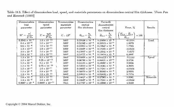
In practical situations there is considerable interest in the central as well asthe minimum Aim thickness in an elastohydrodynamicaHy lubricated conjunc-tion. This is particularly true when traction is considered, since the surfacesin relative motion are separated by a Him of almost constant thickness that iswell represented by the central value over much of the Hertzian contact zone.Table 18.5 shows the effect of the dimensionless load, speed, and materials pa-rameters on dimensionless central film thickness. The formula developed fromcurve fitting the data is
Copyright © 2004 Marcel Dekker, Inc.
USEFUL FORMULAS
481
tp^O
^B
' 33*
^,J3 H ,
s
^'S-g-p
IIg
c g ig
^
" .§
'*C
to
K 8
g8t:
^3 - ^
Q
to
^3 3
.S'Cc ^
a e
tS
H.S^Ei.
^Q3
L,
—
"
'3Cd
§&3
na " ^
g*s 3 Y?
5-S
i!S
3 :
g
°- ^
^1 )
! t
1 t
X X X X X X
000000
1 !
1 1
1 1
X X X X X X
O O O O O O
o o o o o o
o o o o o o
! 1
1 !
1 1
0 O O O 0 0
X X X X X X
O O O O O O
S i
! 1
1 )
O O O O O
g f
m o o
o
C-
^H^M1
11
)1
!0 0 0 O 0 0 0
X X X X X X X
o o o o o o o
1 1
1 !
1 1
10 0 O O 0 O O
X X X X X X X
M tD
--< tD
00 M
O O O O O O O
O O O O O O O
O O O O O O O
1 '
1 '
i I
10 ° 0 g 0 O O
X
X
X X X
" cs
*" [5 ° ° °
O ' O ' w
CO
1 )
1 )
1 i
O 0 0 O 0 0 0
X X X X X X X
S§§g
1 1
i000
XXX
o o o
!
1 1
O 0 0
XXX
00 tD t
O O O
§S^
00°
X X t-
cogo
1 )
000^
X X t0
Copyright © 2004 Marcel Dekker, Inc.
482 FUNDAMENTALS OF FLUID FILM LUBRICATION
1x10*'Dimensionless
speed,
H .8
50x10*'n.6 —
u
= .4
'§ .2
Ei3
Figure 18.14: Varia-tion of dimensionlessfilm shape for threedimensionless speedswith dimensionless
13 ——y/ load and materialsparameters fixed atIV' = 1.3 x 10-**
.04 -.02 o .02 .04 (j = 5007. [FromDimensionless x coordinate, Kg = x / ft,
R^ = J = 2.922 (tF')-'
^The percentage of error was between -7.46 and 6.49%.
18.7.4 Location of Minimum Film Thickness
Figure 18.13 shows the effect of dimensionless load on the tocation of the mini-mum Ami thickness for exactly the same conditions as presented in Fig. 18.11.The location of the minimum film thickness moved toward the outlet as theload was increased. Figure 18.14 shows the effect of dimensionless speed onthe location of the minimum film thickness. The location of the minimum filmthickness did not change much as the speed was increased.
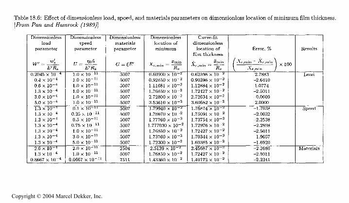
Table 18.6 shows the effect of the dimensionless load, speed, and materialsparameters on the dimensionless location of the minimum film thickness. Theformula developed from curve fitting the data is
y ^min - .,on/n^*-!0'34S—0.011 0.026 /io'?c;\Xe,min = -p— = 1.439 (Vv ) u G (18.75)
The curve fitted formula fits the numerically obtained data with an error be-tween -2.64 and 2.79%.
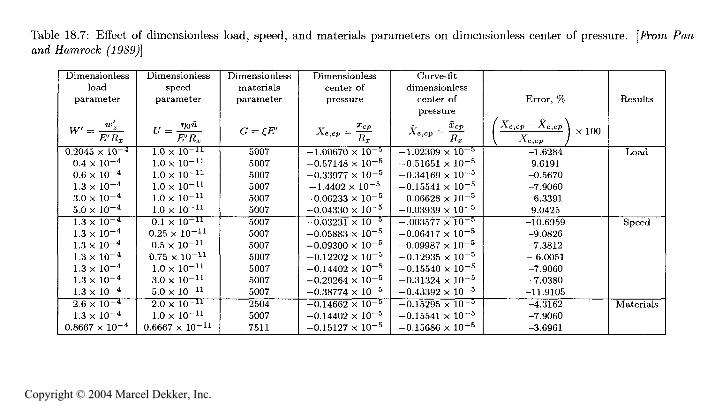
18.7.5 Center of Pressure
The dimensionless center of pressure is expressed in Eq. (18.62). Table 18.7shows how the dimensionless load, speed, and materials parameters affect thedimensionless center of pressure. A least-squares fit of the 16 data sets resultedin the following formula:
Copyright © 2004 Marcel Dekker, Inc.
(HO3M
G
Table 18.6: Effect of dimensionless load, speed, and materials parameters on dimensionless location of minimum film thickness,[ -om Paw awe! FawrocA:
OP
G
Dimensionlessload
parameter
]y/ "
0.2045 x 10*"0.4 x 1Q-"0.6 x 10*"1.3 x 10-"3.0 x 10-"5.0 x 10-"1.3 x 10-"1.3 x 10-"1.3 x 10-"1.3 x 10-"1.3 x 10""1.3 x 10""1.3 x 10*"2.6 x 10*"1.3 x 10""
0.8667 x 10*"
Dimensionlessspeed
parameter
rr I""E'Rx
1.0 X 10""1.0 x 1Q-"1.0 x 1Q-"1.0 x 10*"1.0 x 10*"1.0 x 10*"0.1 x 10*"0.25 x 10-"0.5 x 10*"0.75 x 10*"1.0 x 10-"3.0 x 10-"5.0 x 10*"2.0 x 10""1.0 x 10-"
0.6667 x 10*"
Dimensionlessmaterialsparameter
5007500750075007500750075007500750075007500750075007250450077511
Dimensionlesslocation ofminimum
Xmin
' ''""" Rx
0.60900 x 10-20.92850 x 10*21.11681 x 10*21.76850 x 10*22.72800 x 10*23.53610 x 10*21.79940 x 10*21.78670 x 10*21.77760 x 10*21.777030 x 10-21.76850 x 10*21.73760 x 10"21.72300 x 10-22.5139 x 10-21.76850 x 10*21.43360 x 10*2
Curve- fit
dimensionlesslocation of
film thickness
y. imin
' "'""" Rr
0.62598 x 10*0.90398 x 10*21.12884 x 10-21.72427 x 10-22.72634 x 10-23.60682 x 10*21.76874 x 10*-1.75091 x 10-21.73754 x 10*21.72976 x 10-21.72427 x 10*21.70344 x 10*21.69385 x 10*22.45687 x 10*1.72427 x 10*21.40172 x 10-2
Error, %
/ j . __ j . \
\ e min 7 '
2.7883
-2.64101.0774-2.5011-0.06092.0000-1.7038-2.0032-2.2538-2.2898-2.5011-1.9657-1.6920-2.2686-2.5011-2.2241
Results
Load
Speed
Materials
Copyright © 2004 Marcel Dekker, Inc.
484FUNDAMENTALS OF FLUID FILM LUBRICATION
a0-8s*cQ)$EO o{*
^ oo
o os
tg^
M
t c
06 g^
?
a) !H3
*!3
E5 §
^§X
'f.g M
^^
& -S g
&
S O D-
J
ac g <S o
.B ^ Q.
as"a ^
' oF
'g $ ^
&3S &
S ii
S g.
^
*§ 3 ^ ?
'K a s
^S -
S !i
S
^
oto tn 01 co
"l *?
"?*?"? t
X X X X X X
r 0 0 O 0 0
1 !
1 1
1 1
"l t
"l "f "
*?0 0 0 0 O
X X X x X X
7 i
i ' i i
^^
11
)1
1!
X X X X X X
O 0 0 0 O O
-*g i
) t
I I
^ f
CO 0 0
o
o.
S s
::S g
co oi t-: "
1 *
^
1 1
1 I
O 0 0
C
XXX)
f-
00
C<
°. d d
c1
1 1
o o o
eXXX)
r CO O
CO 00 O C
C 00 CO
C
o o o
-o o o
c!
1 1
0°
X X x ^
° d o
c
I I
I I
XXX)
CO CO CO
C" S §
S °?^
f 1* *?
3 0 0 O
< X X X
3 O O 0
1 1
1
3 O 0 0
(XXX
'l f d t
^ f Ol 00
^
C<l CO
I !
1
- t- t- r-3000
3 O O 0
3 <
' '
^ 0 O O
^ X X X
^ 0 O O
^ w co -n
i 1
3 O O O
< X X X
3 CO CO CO
Materials
g§§
mXXX
1 1
1
O 0 0
XXX
1 1
1
ggg^o o
***
""
XX X t-
00 gd.
00°
X x r-
tD CO go
Copyright © 2004 Marcel Dekker, Inc.
CLOSURE 485
X, ,p = = -3.595 (tV'rT
The percentage of error was between -11.91 and 9.62%.
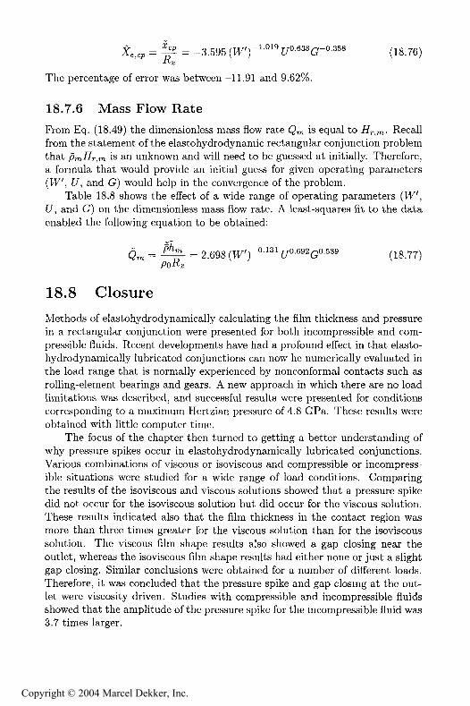
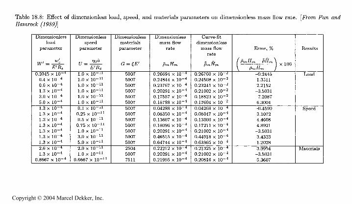
18.7.6 Mass Flow Rate
From Eq. (18.49) the dimensionless mass How rate Q^ is equal to R^.m- Recallfrom the statement of the elastohydrodynamic rectangular conjunction problemthat /9mRr,m is an unknown and will need to be guessed at initially. Therefore,a formula that would provide an initial guess for given operating parameters(tV, y, and G) would help in the convergence of the problem.
Table 18.8 shows the effect of a wide range of operating parameters (tV,[7, and G) on the dimensionless mass flow rate. A least-squares fit to the dataenabled the following equation to be obtained:
= 2.698 (tV')-°'
18.8 Closure
Methods of elastohydrodynamically calculating the film thickness and pressurein a rectangular conjunction were presented for both incompressible and com-pressible fluids. Recent developments have had a profound effect in that elasto-hydrodynamically lubricated conjunctions can now he numerically evaluated inthe load range that is normally experienced by nonconformal contacts such asrolling-element bearings and gears. A new approach in which there are no loadlimitations was described, and successful results were presented for conditionscorresponding to a maximum Hertzian pressure of 4.8 GPa. These results wereobtained with little computer time.
The focus of the chapter then turned to getting a better understanding ofwhy pressure spikes occur in elastohydrodynamically lubricated conjunctions.Various combinations of viscous or isoviscous and compressible or incompress-ible situations were studied for a wide range of load conditions. Comparingthe results of the isoviscous and viscous solutions showed that a pressure spikedid not occur for the isoviscous solution but did occur for the viscous solution.These results indicated also that the film thickness in the contact region wasmore than three times greater for the viscous solution than for the isoviscoussolution. The viscous film shape results also showed a gap closing near theoutlet, whereas the isoviscous film shape results had either none or just a slightgap closing. Similar conclusions were obtained for a number of different loads.Therefore, it was concluded that the pressure spike and gap closing at the out-let were viscosity driven. Studies with compressible and incompressible fluidsshowed that the amplitude of the pressure spike for the incompressible fluid was3.7 times larger.
Copyright © 2004 Marcel Dekker, Inc.
486FUNDAMENTALS OF FLUID FtLM LUBRICATION
.2'o
p& h
^^-1
s Y
H
- e
^ '
^ g].
to c
o g
j, 0 tO
,g
0 § a " "
Sc^ &
.S^3
E
p 3 "**'*
Q^
c c a
O.5 °
n. ^
Q«=—
S3 3
^
'§ *$ S ^ K)
g Q. g
1!
S
n. ^
°g
^
H-
S3
-.« eg°
*O "
^ EQ
g g
!!
S
S* ^
^^^^§^S
I c
j
j to
1 i
! 1
! !
X X X X X X
§s^§s§
C
CN C w
CD 0 0 0 CD 0
,y
.3, , T, ,y
.
i i
1 1
! 1
O O CD O CD CD
X X X X X X
S S °
w
CD CD
CD CD
CD CD
,,^
*i* 1*
1* 1*
1* 1*
3 3 3 S 3 S
X X X X X X
CD CD
CD CD
CD CD
^3 I
! i
1
to X X X X X
C CD
CD -w
CO LO
CD
^^^S^S§5S
) CO
f f
i M
--
1 1
1 1
) i
1
X X X X X X X
sssSsssO CD
C4 to
CD CD CD 0 0 CD CD
^
. .
.
. sy
i !
1 1
1 1
1
X X X X X X X
ggggss^CD
CD CD
CD CD
CD CD
&& 00 0& &
i* 1 7 1* "V 1* 1*
o 3 3 o o o
x x x * x x x
i <3 " tS °. p °.° 0 ° 0 "
) 1
1 1
1 1
1
x x x x x x x
3Ss° §01 "
CO
CO i
U3
1 1
1O O O
XXX
iasset cN co o o
[3 T
-J
! 1
1O CD O
XXX
g°2
000
...^
^^o
0 O "
x x r-
q o gd^
' '
30 O
X X t-
C-J 00
b
Copyright © 2004 Marcel Dekker, Inc.
PROBLEMS 487
Having explained the details of the pressure and film shape, the chapterturned to studying the influence of the operating parameters on the perfor-mance parameters and to developing simple formulas that relate the two. Theoperating parameters that were studied were the dimensionless load, speed,and materials parameters. The dimensionless load parameter tV' was variedfrom 0.2045 x 10" to 5.0 x 10" . The dimensionless speed parameter f/ wasvaried from 0.1 x 10" to 5.0 x 10" . And the dimensionless materials pa-rameter G had values of 2504, 5007, and 7511, corresponding to solid materialsof bronze, steel, and silicon nitride, respectively. Fourteen cases were investi-gated, covering a complete range of operating parameters normally experiencedin elastohydrodynamic lubrication. Formulas were obtained for the followingperformance parameters: pressure spike amplitude and location, minimum andcentral film thicknesses, location of the minimum film thickness, location of thecenter of pressure, and mass How rate.
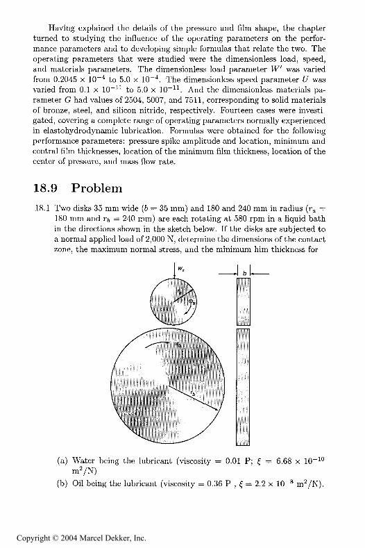
18.9 Problem
18.1 Two disks 35 mm wide (& = 35 mm) and 180 and 240 mm in radius (r =180 mm and r = 240 mm) are each rotating at 580 rpm in a liquid bathin the directions shown in the sketch below. If the disks are subjected toa normal applied load of 2,000 N, determine the dimensions of the contactzone, the maximum normal stress, and the minimum him thickness for
(a) Water being the lubricant (viscosity = 0.01 P; $ = 6.68 x 10" °m2/N)
(b) Oil being the lubricant (viscosity = 0.36 P , $ = 2.2 x 10"S m /N).
Copyright © 2004 Marcel Dekker, Inc.
488 FUNDAMENTALS OF FLUID FILM LUBRICATION
Assume the disks are made of steel with a modulus of elasticity of 2.1 xN/m^ and Poisson's ratio of 0.3
References
Barus. C. (1893): Isothermals, Isopiestics, and Isometrics Relative to Viscosity.Xm. J. Re!., vol. 45. pp. 87-96.
Crook, A. W. (1961): Elasto-Hydrodynamic Lubrication of Rollers. JVa^we,vol. 190, p. 1182.
Dowson. D., and Higginson, G. R. (1959): A Numerical Solution to the Elas-tohydrodynamic Problem. J. AfecA. J5n<?. <?c:., vol. 1. no. 1, pp. 6-15.
Dowson. D., and Higginson, G. R. (1966): E/as o/tyo'roa'yKanw LM^Wca^on,T/te Funa'ameH s o/ RoMer ana* Gear LtibWca^on. Pergamon, Oxford.
Ertel, A.M., (1939) "Hydrodynamic Lubrication Based on New Principles,"ao*. #au R. PW aa'naya AfaiAema^ca ! AfeMan^a, vol 3, pp. 41-52.
Grubin. A. N. (1949): Fundamentals of the Hydrodynamic Theory of Lubrica-tion of Heavily Loaded Cylindrical Surfaces, in Awes^aMoK o/ t e ContactAfacAme Co?npowe?t . Kh-. F. Ketova, (ed.). Translation of Russian BookNo. 30. Central Scientific Institute for Technology and Mechanical Engi-neering, Moscow, Chapter 2. (Available from Department of Scientific andIndustrial Research, Great Britain, Trans. CTS-235 and Special LibrariesAssociation. Trans. R-3554).
Hamrock, B. J., and Jacobson, B. O. (1984): Elastohydrodynamic Lubricationof Line Contacts,. yl LE Tra?M., vol. 24. no. 4. pp. 275-287.
Hamrock, B. J., Pan, P., and Lee. R. T. (1988): Pressure Spikes in Elastohy-drodynamically Lubricated Conjunctions. J. TWM., vol. 110. no. 2, pp.279-284.
Houpert, L. G., and Hamrock, B. J. (1986): Fast Approach for Calculating FilmThicknesses and Pressures in Elastohydrodynamically Lubricated Contactsat High Loads. J. 7HM., vol. 108, 110. 3. pp. 411-420.
Okamura, H. (1982): A Contribution to the Numerical Analysis of IsothermalElastohydrodynamic Lubrication, in THMofyyo/RectprocatrngErtfywes. D.Dowson et al. (eds.). Butterworths, Guilford, England, pp. 313-320.
Pan, P., and Hamrock, B. J. (1989): Simple Formulae for Performance Param-eters Used in Elastohydrodynamically Lubricated Line Contacts. J. TW&o%.,vol. Ill, no. 2. pp. 246-251.
Petrusevich, A. I. (1951): Fundamental Conclusions From the Contact-HydrodynamicTheory of Lubrication. J . a& JVaM&., &S3R. OM. TeAA. JVat&, vol. 2,pp. 209-233.
Roelands. C. J. A. (1966): Corre MnaZ 4 pec o/^/te VMCos^y-Tempera^Mve-
Presswe Re^a^ons/Mps o/ Ltt6ftcatton (Ms, Druk. V. R. B. Groningen.
Netherlands.
Copyright © 2004 Marcel Dekker, Inc.