dk7740a wire cut
TRANSCRIPT

DK7740A
CNC EDM WIRE CUTTING MACHINE
TECHNOLOGY DOCUMENTS
SERIAL NUMBER:
SUZHOU ZHONGGU MACHINE & ELECTRONIC TECHNOLOGY CO., LTD
THE PEOPLES REPUBLIC OF CHINA

Suzhou Zhonggu Machine & Electronic Technology Co.,Ltd Addr: 888 Chenyang Rd, Xiangcheng District, Suzhou, China. Tel: +86-0512-85185518 FAX: +86-0512-85185515 Website: www.zgedm.com email: [email protected]
TECHNOLOGY DOCUMENTS CONTENT
1. USER’S MANUAL
2. PARKING LIST
3. WARRANTY CARD

Suzhou Zhonggu Machine & Electronic Technology Co.,Ltd Addr: 888 Chenyang Rd, Xiangcheng District, Suzhou, China. Tel: +86-0512-85185518 FAX: +86-0512-85185515 Website: www.zgedm.com email: [email protected]
CNC EDM WIRE CUTTING MACHINE
INSPECTION CERTIFICATE
WORKTABLE TRAVEL: 500×400
WORKTABLE DIMENSION: 720×460
SERIAL NUMBER:
SUZHOU ZHONGGU MACHINE & ELECTRONIC TECHNOLOGY CO., LTD
THE PEOPLES REPUBLIC OF CHINA
ZGEDM
MACHINE:
DK7740A
Suzhou Zhonggu Machine & Electronic Technology Co.,Ltd Addr: 888 Chenyang Rd, Xiangcheng District, Suzhou, China. Tel: +86-0512-85185518 FAX: +86-0512-85185515 Website: www.zgedm.com email: [email protected]
DK7740A CNC EDM WIRE CUTTING MACHINE
THIS MACHINE HAS PASSED ALL INSPECTION ITEMS AND SALE ALLOWED
MANAGER (SIGN)
INSPECTOR (SIGN)
DATE: YEAR MONTH
SUZHOU ZHONGGU MACHINE & ELECTRONIC TECHNOLOGY CO., LTD
THE PEOPLES REPUBLIC OF CHINA

DK77 Series EDM Wire Cutting Machine
User's Manual

Suzhou Zhonggu Machine & Electronic Technology Co.,Ltd Addr: 888 Chenyang Rd, Xiangcheng District, Suzhou, China. Tel: +86-0512-85185518 FAX: +86-0512-85185515 Website: www.zgedm.com email: [email protected] I
NOTICE
1. We provide one year warranty for machine principally.
2. Service contents: Mechanical and electrical malfunctions under normal working
environment and correct operations.
3. Please pay attention during warranty:
1) Any problems caused by input voltage problem (input voltage must be 380V 20V) are
not in warranty.
2) Any problems caused by nature disaster like fire, flood or thunder are not in warranty.
3) Any problems caused by operation mistakes are not in warranty.
4) Users should not add any new peripheral in the computer, change any devices in the
computer or modify the operation system. Problems caused by virus are not in warranty.
5) If above cases occurs, we have to charge when provide the service.
6) The wear parts on the machine are not including in warranty.
7) (Wire cutting machine’s wear parts: pulleys, guide wheel, conductor block and etc.)
(Drilling machine’s wear parts: electrode, chuck, seal rubber, guide, timing belt and etc.)
We do not provide any warranty service if the customer does not take the payment on
terms.
8) Please contact us with out hesitates when you face any operation questions. If you don’t
have proper operator, please contact us and we will provide training courses in our
company.
4. We will provide service over life of the machine in charge after warranty.

Suzhou Zhonggu Machine & Electronic Technology Co.,Ltd Addr: 888 Chenyang Rd, Xiangcheng District, Suzhou, China. Tel: +86-0512-85185518 FAX: +86-0512-85185515 Website: www.zgedm.com email: [email protected] II
INSTALLATION
Dear user,
Kindly please under the instructions to install the machine properly after you open
package:
1. Please check all items on the parking list.
2. Please read the manuals and technology documents carefully before you start the
machine.
3. Please take off all block junctions on the machine, sweep the seal grease and lubricate
all parts of machine.
4. Please adjust the level of machine’s work table.
5. The power supply must be 3 phase 380V 50Hz voltage. Please connect the PE terminal
to protect earth for safe. Otherwise we do not take charge of any electrical shock.
Thank you very much for your cooperation!
Suzhou Zhonggu Machine & Electronic Technology Co., Ltd

1
Part 1 Machine Introduction
DK77 series CNC EDM Wire Cut is consisted with machine basement, worktable, wire
drum, wire shelf, working fluid circulation system and machine electric and CNC system.
The CNC controls worktable running in X, Y direction according to the post accurately. The
wire runs cyclically from the wire drum to upper and lower guide rollers in high speed.
There’s high frequency pulse electron discharging between wire and workpiece on
machining, the discharging path generates high temperature to erode metal. The ashes of
melted metal are washed out by the working fluid.
There’s place to install taper device (Option) on the front of wire arms. The taper device
can rotate wire in U and V direction. The machine can perform interpolation movement in X,
Y and U, V axes to cut taper parts and upper/lower dual-shape parts.
1. Machine Basement
The machine basement is a completed casting, installed machine electrical parts inside
and worktable, wire drum, wire arms on it. The working fluid tank is put beside it.
2. Worktable
The worktable is consisted with upper carriage, middle carriage, ball screws and guides.
The worktable on carriages moves on roller guides or linear guides that driven by high
precision ball screws which controlled by step motor with gear box.
The producer has adjusted and tightened the ball screws in a proper way. Please do
NOT disassemble them without professionals.

2
3. Wire System
The wire system controls molybdenum wire running cyclically along the path consisted
by wire drum, upper rollers and lower rollers. The wire drum is made in a thin cylinder that
insulated with drum spindle. It rotates in 11m/s linear velocity to send out the wire and runs
on guides go and back to keep the wire route in the proper position.
The wire drum changes running direction when touch limit switches. This circuit of limit
switches is simple, high response, low noise and long life. There’s another over travel
switch to stop machine running only if the limit switches are out of work.
The wire shelf is consisted by column, fixed arm, mobile arm and guide rollers. The
carbide conduct blocks are installed on the front of fixed and mobile arms respectively. And
the guide rollers, conduct blocks are insulated against wire arms. The wire’s path is open,
firstly, the wire go out from the wire drum to tension adjustment device on column, then go
to the conduct blocks in front via upper guide roller, and pass the upper and lower muzzles,
back to wire column via lower guide roller finally. The workpiece is fixed between upper and
lower muzzles. Operator shall align the wire to vertical position before machining.
There’re 2 valves inside the column, and the valves’ knobs are on the column to adjust
the flux of working fluid from upper and lower muzzles.
Turn the hand wheel on the top of column can move the mobile arm up and down to
adjust the height between guide rollers to adapt different height of workpieces.
The operator shall keep the guide rollers, conduct blocks and wire arms clean to get
good machining results.

3
The pump on working fluid tank deliveries working fluid via valves to muzzles in the
front of arms to shoot work fluid to workpiece from up and down sides at same time when
machining to wash out the ashes of metal. The working fluid drops in the box gutter flume
then flows back to tank. And the dirty working fluid could be filtered and settled in it. Please
clean the tank in time.
The working fluid is mixed by WEDM soap scream and clean water in rate 1:20.
4. Operation Notices
1. The wire is powered by electricity when machining, it may cause people be shocked if
touch on it. The operator shall take essential protection wares and do NOT touch the
discharging parts when machining.
2. Connected the machine tool to protection ground tightly.
3. Choose the coordinate according to workpieces or design drawings properly to
calculate and generate the post. The operators shall consider the clamping method and
wire diameter in advance and choose a proper start point.
4. Please check the post program carefully before machining. And if the part is complex,
the operators could dry run the machine to simulate the work path to test the post.
5. The operators shall consider the worktable travels when clamping workpiece and
posting program. In case of small parts and high difficulty parts, the operators must put
workpiece on worktable properly to avoid over travel problem.
6. Please drill small holes in right position to through the wire before machining on molds
that can not be cut from out side.

4
7. Check the wire tension before machining. If the wire is losing, tighten it by the tools in
time.
8. Put on the protection cover on wire drum and close the door of cabinet before
machining. Do NOT take off the cover to avoid wire throw off if wire broken.
9. Start the wire drum first and check if it runs well, then turn on the pump, and turn on high
frequency at last to start machining. Turn off them backwards when finished.
5. Runs Machine in Good Conditions
The principle factors to influence machining precision and methods to improve
machining precision:
Apparently, the machine motion precision influences the working result precision
directly. But the discharging gap and workpiece distortion will influence the machining
precision during cutting besides the machine motion precision as well.
1. Machine precision: Even the machine tool is inspected in proper conditions by the
producer before delivery, but the user shall check it again before machining precise parts
and adjust it if necessary.
(1). Check guide rollers: Operator shall check the guide rollers’ V-shape slot to see if it
was worn out carefully before machining, see Fig-1.
The wire is running in high speed in the V-shape slot during machining and it would
cause some discharging and friction, the guide rollers’ V-shape would form a deeper slot
underneath. It will cause the wire vibrate, make bad machining result and break the wire,
please change the worn out rollers in time. And please often clean the dirt in V-shape.

5
正常 已磨损
Fig-1
(2). Check conduct blocks: The conduct blocks are made in carbide, please check if
there’s slot on it before machining. If the wire is inserted into the slot, please rotate it to
change the touch position or change the blocks.
(3). Check the backlash in X, Y ball screws: The backlash would change after a long
time working, in case of machining high precision parts, please check it and adjust it if
necessary to standard value before machining.
2. Discharging gap: The discharging gap between wire and workpiece are influenced
by material, cutting speed, working fluid and etc.
(1). Discharging gap changing: Because the difference from materials, heat treatments
or workpiece thickness, the discharging gap is changing. The material’s chemical
characters, physical characters and flux of working fluid would change the gap as well.
(2). Relationship of discharging gap and cutting speed (working current): The
relationship between them is like a parabola, the gap is smaller when the cutting speed is
faster in a specific range. But the cutting speed must slower than the eroding velocity,
otherwise the wire and workpiece are short circuit and stop machining. Keep the current
stable to keep erosion voltage stable and gap stable. So choose a set of proper time on

6
(Ton), time off (Toff) and other parameters to get a stable condition. Normally, operators
choose big Ton on roughing to increase the cutting speed, and small Ton on finishing. Keep
the current stable to keep the cutting speed regularity to guarantee the machining results.
(3). Relationship of discharging gap and working fluid: The difference from working fluid
components, the resistances, wash out abilities and dielectric abilities of fluid are different.
All these factors can change the gap. So in finishing, the operator must choose a proper gap
composition when posting the program.
3. Method to decrease workpiece distortion: The principle sequence for finishing
steel parts on WEDM shall follow the steps: raw material, forging, anneal, rough machining,
quenching, temper, grinding, EDM wire cutting, handcraft by locksmith. There’re 2 chances
in this machining linkage to make big distortion and influence cutting precision. The material
suffers the first distortion on rough machining, and the second distortion on temper. These
distortions can not be ignored in high precision parts.
For example, see Fig-2, when cutting the tempered steel square, on the wire path from
A to B, the steel square could change itself as the dash line shown. As a result, the finished
part is different from the design, if there’s stain stress in the material, the width of the cut
down square would be wider, or if there’s press stress inside, the cut down square would be
narrower.

7
切割加工后钢材变形情况 切割孔类工件变形情况
Fig-2
On the right of Fig-2, we illustrate a distortion on machining part with a hole. During the
machining of cutting the square hole, because of the stress inside material, the square hole
would be like a tambour in dot line or a saddle in dash line. Sometime the distortion would
take a more important part of role on machining precision than machine precision itself.
Sometimes users can see the distortion by eyes and even the material would explode on
machining.
In order to avoid big distortion on materials, we analyzed molds and parts distortion
factors under our knowledge in long time machining, we suggest follow below methods:
(1). Choose small distortion materials as possible as you can. These materials are
CRWMN, CR12M0, GCR15 and other alloy tool steel.
(2). Try the best to lower the stress on forging and anneal.
(3). Choose proper techniques and operation in right way on quenching and temper.
Set the temperature as low as possible to lower limit and coolant equally on quenching. And
set the temperature as high as possible to higher limit with enough time. Operation in this
way can eliminate the stress as much as possible after heat treatment.
(4). Methods on techniques:

8
A. Arrange the cold and heat steps properly to prepare for the heat treatment as last to
decrease the stress and distortion. For high precision parts, temper the part in how
temperature after cutting to stable the size.
B. Do not cut the mold from outside of workpiece directly but make a hole to though the
wire beside the edge of workpiece. And the cutting range should not near the workpiece
edges to guarantee there’s enough intensity on workpiece to against the stress inside. See
Fig-3.
坯料
凸模
穿丝孔
尺寸一般在 -18mm,若凸模轮廓尺
寸较大或凸模材料淬透性较差,则B尺寸
也要相应放大。
Fig-3
C. It is better to use twice cutting for upper punch molds on workpiece that grinded and
tempered. The workpiece distortion is about 0.03mm, so better left 0.12-0.2mm (in the case
of use 0.18mm molybdenum wire) cutting allowance per side and cut it in a higher speed.
After the first cutting, the balance of stress inside the workpiece would be rebuilt to a new
balance. Then cut to demand size to get a better precision.
D. Machining the shape before heat treatment and left 0.6-1mm machining allowance
for lower punch molds. In this case, the mold’s material distorted big enough during heat
treatments. While the cutting allowance is quite small and would not break the stress inside

9
workpieces and the parts would not distort after cutting. For some low hardenability
materials, this technique keep and increase the shape harden and improve the quality of
mold.
E. Choose the start point near workpiece’s gravity center and clamp it properly. When
cutting to the closed point, the workpiece would distort little.
F. Add some supports in proper position for big workpiece to decrease the distortion
caused by the gravity of cut down part.
G. For small parts and long semi-manufacture parts, there’re too much factors to avoid
all distortion. In this case, we suggest users adopt check and cut mixed method, measure
the part during machining and modify posting program in time to get the design demands.
4. Analysis of cutting surface: The metallographic analysis and surface hardness test
indicate there’s a harden layer in different thickness and discrete, harder than before on the
surface. The thickness of this layer is about 5-30um, hardness is about HV100 and like
re-quenched. But there’s another lower hardness layer about 2-4um thick attached, and
maybe with some small cracks. So the 0.01mm thick on top of surface is not wearable. To
increase the molds quality, when making small clearance fit molds, users shall left some
allowance for grinding by hand.

10
6. Lubrication System
No Lubricate part Frequency Method Oil
1 X axis ball screw Every day Oil gun 30# Oil
2 Y axis ball screw Every day Oil gun 30# Oil
3 X axis screw nut Every day Oil gun 30# Oil
4 Y axis screw nut Every day Oil gun 30# Oil
5 Wire drum linkage Every day Oil gun 30# Oil
6 Wire drum screw nut Every day Oil gun 30# Oil
7 Wire drum guides Every day Oil gun 30# Oil
ATTENTION: 1. Change the high speed grease on the guide rollers every 2 weeks
2. Change other bearings every half year
3. Motors’ bearings shall be lubricated under motors’ manual
7. Machine Transporting and Installation
Left the machine under the wooden pallet.
Open the wooden box in workshop, don’t hit the box.
Take off the cover of box first, and then take off the walls (or wrapped plastic bag). Take
out the tool box and clean the protection grease. Then put the machine on hard ground with
machine feet. Take off fixed iron parts on machine. Clean worktable to adjust horizontal
level of the machine (horizontal level is 0.04/1000). Then connect all cables and check the
precision of machine.
Stands the machine on hard concrete ground and separate with vibration source and
electrical magnetic noise.

11
8. Machine Maintenance
Often clean the machine is the best way to keep the machine precision and long life,
improve work efficiency. Please taking care the following matters:
1. Lubricate the machine with clean oil in time according to the manual.
2. Move all movable parts by hand to check if all in good condition before turn on the
machine.
3. The machine shall work in environment temperature 5-35°C, humidity 40-75﹪, air
pressure 86-110KPa. In order to get the best cutting result, keep the temperature
constantly about 20°C.
4. Clean the machine after working and put on grease on the easy rust parts. Clean the
machine completely on time.
5. If there’s any problem during machining, please stop working and contact professionals
to repair it.
6. Read the operation manual carefully before operation on machine.

12
Part 2 Mechanism
1. Machine Tool Usage
EDM wire cutting machine DK-series consists of Numeric Control,High Frequency
Power Generator and Machine Body. This machine tool is used to process metal dies,
patterns and mechanical parts used in electronic apparatuses, precision machines,
commercial industry and military industry etc, with high precision, high stiffness and high
toughness.
2. Machines Specifications
Machine Type DK7732 DK7740 DK7750 DK7763 DK7780
Worktable Dimension
366×576 410×690 550×850 720×1100 820×1300
Worktable Travels
320×400 400×500 500×630 630×800 800×1200
Max Machining Thickness
400mm 400mm 500mm 500mm
(800mm Optional) 500mm
(1200mm Optional)Max Machining Taper
0~60°/100mm (Optional)
Max Cutting Speed
≥180mm2/min
Best Surface Roughness
Ra≤0.8um
Wire Diameter 0.10-0.2mm
Wire Running Velocity
11m/s
Working Fluid Water mixed with soap
Precision Accord to standard GB7926-87
Movement Vector 0.001mm
Power Source AC.380V.50Hz
Power Dissipation ≤2.2kw
Max Load Weight 250kg 320kg 600kg 1000kg 1200kg
13
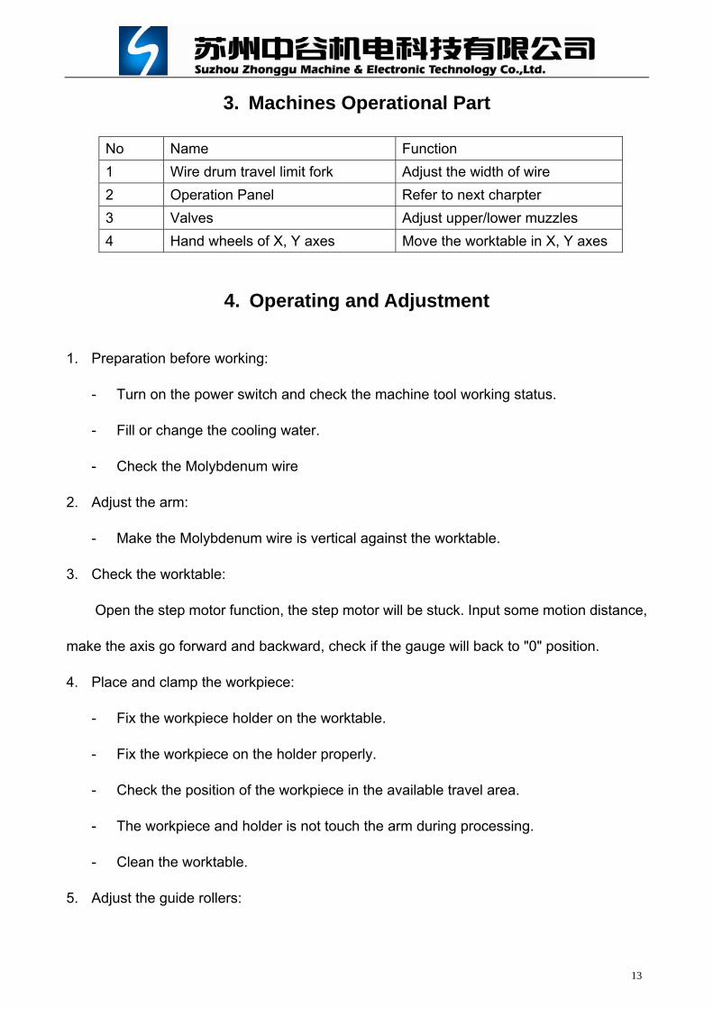
3. Machines Operational Part
No Name Function
1 Wire drum travel limit fork Adjust the width of wire
2 Operation Panel Refer to next charpter
3 Valves Adjust upper/lower muzzles
4 Hand wheels of X, Y axes Move the worktable in X, Y axes
4. Operating and Adjustment
1. Preparation before working:
- Turn on the power switch and check the machine tool working status.
- Fill or change the cooling water.
- Check the Molybdenum wire
2. Adjust the arm:
- Make the Molybdenum wire is vertical against the worktable.
3. Check the worktable:
Open the step motor function, the step motor will be stuck. Input some motion distance,
make the axis go forward and backward, check if the gauge will back to "0" position.
4. Place and clamp the workpiece:
- Fix the workpiece holder on the worktable.
- Fix the workpiece on the holder properly.
- Check the position of the workpiece in the available travel area.
- The workpiece and holder is not touch the arm during processing.
- Clean the worktable.
5. Adjust the guide rollers:
14
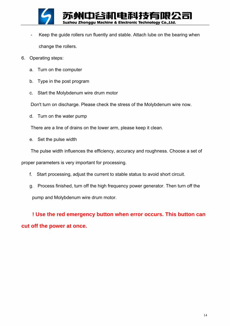
- Keep the guide rollers run fluently and stable. Attach lube on the bearing when
change the rollers.
6. Operating steps:
a. Turn on the computer
b. Type in the post program
c. Start the Molybdenum wire drum motor
Don't turn on discharge. Please check the stress of the Molybdenum wire now.
d. Turn on the water pump
There are a line of drains on the lower arm, please keep it clean.
e. Set the pulse width
The pulse width influences the efficiency, accuracy and roughness. Choose a set of
proper parameters is very important for processing.
f. Start processing, adjust the current to stable status to avoid short circuit.
g. Process finished, turn off the high frequency power generator. Then turn off the
pump and Molybdenum wire drum motor.
! Use the red emergency button when error occurs. This button can
cut off the power at once.

15
5. Troubleshooting
No Troubles Causes Solutions
1 Wire dent on the workpiece surface
1. wire is loose 2. the table is not balance 3. cut tract is not stable
1. stress the wire or replace the wire2. check the table 3. adjust the parameters
2 Wire shaking
1. wire is loose 2. V-channel on the pulleys
wear out 3. vibration during turn
direction 4. wire is bended
1. stress the wire or replace the wire2. replace the pulleys and bearings 3. adjust or replace the spindle 4. replace the wire
3 Rollers run not agility
1. too wide in the pulley bearings
2. trashes go into pulleys 3. pulleys and bearings wear
out
1. adjust the pulley 2. wash the pulleys in the coal oid 3. replace the pulleys and bearings
4 Wire break
1. wire wears out 2. wire shaking heavy 3. lack of cooling water, the
trash can't be pushed out 4. parameters are not fit the
processing, cause short circuit
5. there is oxidation layer on the workpiece surface
1. replace the wire 2. check the cause of wire shaking 3. adjust the flow of cooling water 4. choose proper parameters 5. cut the oxidation layer off the
workpiece
5 Bad accuracy
1. low accuracy in the X, Y –axis motion.
2. low vertical accuracy 3. pulleys and bearings wear
out 4. controller and the step
motor lost the control pulse, the table not back the "0" position
1. check and adjust the spindles 2. check and adjust the vertical
position 3. adjust or replace the pulleys and
bearings 4. check and adjust the controller or
replace the step motor.

16
6. Wear Parts
Part Name Quantity Installed Position
Conduct Block 3 Upper/lower wire arms
Guide roller assembled 2 Upper/lower wire arms
Wire drum junction 3 Connection drum and motor
Muzzle 2 Upper/lower wire arms

17
Part 3 Electrical
The machine electrical equipments take the role of controlling wire drum’s motor
running and directions, pump running, wire broken protection and other protection functions.
For more details, please refer to the Electrical Schematics.
Parameters set
This kind of machine is upgraded from high speed wire cutting, but it is completely
different from the controller. It is upgraded parameter setting to computerized from IC digital
setting, upgraded wire running speed to variable from constant. These upgrades realized
multiple cutting in finishing surface performance. But there’re a lot of factors that influence
the finishing result besides pulse parameters, discharging parameters. These factors
include the molybdenum quality and diameter, working fluid type and etc. Even a settled set
of parameters would performance different result because of the experiences of operators,
workpiece materials and heat treatments. In this case, the operators not only shall follow the
parameters table, but also have to practice during working.
The principle rule of multiple cutting is cut once and trimmed twice. The high frequency
pulse parameters are divided into 3 settings of BIG, MID, and SMALL. The BIG is for the
first cutting, and MID is for first trimming, SMALL is for second trimming. Choose No.3, No.2
and No.1 on the computer to get the 3 type of high frequency pulse.
For example, to cut a diameter 10mm and 40mm height column in multiple cutting:

18
High frequency pulse No.3, 2 and 1
Ton (us) Toff Power Inverter(Hz)
No.3 for rough cutting 7 2 7 2
No.2 for first trimming 10 1 15 4
No.1 for finishing trimming 13 1 15 6
Attention: The bigger Ton, the higher efficiency and bigger discharging gap.
The smaller Ton will make machining stable but lose efficiency.
The bigger current will get big cutting velocity but lower the stability and
increase wire’s wear.
The lower servo voltage, the higher efficiency but may not stable.
The higher Inverter (Hz) can wash out ashes faster and make machining
faster and easier.

19
1. Plugs Definition
30PIN PLUG
Pin No. Label Comment Pin No. Label Comment
1 PE Ground 16 05 Drum motor off (NC)
2 24V1 17 03 Drum motor off led
3 24V2 Lamp power
18 12 Drum change direction
1 (NO)
4 19 AL2 Emergency Stop
5 20 02 Drum motor on(NO)
6 21 13 Drum change direction
2 (NC)
7 4L+ 22 COM
8 4L+ 23 16
9 4L+ 24 01 Drum motor on(NO)
10 4L+
4 axes step motors’ COM
25 543 Wire broken protection
11 UY 26 220 Wire broken protection
12 VY 27 AL4 Emergency Stop
13 WY
Drum’s motor
28 PM- Negative sample
14 +24 +24V power 29 PM+ Positive sample
15 04 Drum motor off (NC) 30

20
20PIN PLUG
Pin No. Label Comment Pin No. Label Comment
1 PE Ground 11 YB Yellow
2 12 YC Blue
3 13 YD White
4 14 YE Black
5 XA Red 15 UA
6 XB Yellow 16 UB
7 XC Blue 17 UC
U axis
8 XD White 18 VA
9 XE Black 19 VB
10 YA Red 20 VC
V axis
4PIN PLUG
Pin No. Label Comment Pin No. Label Comment
1 W Pump power phase W
2 V Pump power phase V
3 U Pump power phase U
4 PE Ground

21
Signals for controller on PCI slot (25PIN)
1 XA 14 UA
2 XB 15 UB
3 XC 16 UC
4 XD 17 VA
5 XE 18 VB
6 YA 19 VC
7 YB 20 TK0
8 YC 21 TK1
9 YD 22 PJD1
10 YE 23 PJD0
11 12V- 24 PM-
12 PJD2 25 PM+
13 12V+
TK0, TK1, TK2 are stop condition signals. TK0, TK1 are normal open (NO); TK0, TK2 are normal closed (NC).
PJD0, PJD1, PJD2 are high frequency singles. PJD0, PJD1 are normal open (NO); PJD0, PJD2 are normal closed (NC).
PM-, PM+ are discharging sample.
Signals for controller on PCI slot (9PIN)
1 12V- 6
2 ZA 7 TK0
3 ZB 8 TK1
4 ZC 9 TK2
5 12V+
Attention: never short circuit 12V- with PM-, the 12V is supply by extend device.
Jumper: Short the 25PIN’s no.13 with 9PIN’s No.5. Short the 25PIN’s No.20 with 9PIN’s No.9 (Stop signal).
Break circuit the second machine stop line on front (change signals from NO to NC)

22
15 PIN SLOT(J7) Mitsubishi Inverter
Tyco Inverter
Comment
1 RUN SYN+ A: frequency level
2
3 C RELAY B: alarm signal
4 SE SYN- A: Cut off high frequency when direction changing
5 SD COM COM
6 B TRIP B: out put relay
7
8
9
10 STF FWD Motor runs CW
11 RL SP1 Frequency segment No.1
12 RM SP2 Frequency segment No.2
13 RH SP3 Frequency segment No.3
14 PC FM+
15 STR REV Motor runs CCW
Central control board’s J8 Plug to 30 PIN PLUG
J8 30 PIN PLUG J8 30 PIN PLUG
1 14 +24 9 22 COM
2 15 04 10 23 16
3 16 05 11 24 01
4 17 03 12 25 543
5 18 12 13 26 220
6 19 AL2 14 27 AL4
7 20 02 15 28 PM-
8 21 13 16 29 PM+
Central control board’s J10
1 High frequency KM1 7 B1-0V
2 Pump KM2 8 A4-12V
3 A1-110V 9 B4-0V
4 A6-6V 10 A2-20V
5 B6-0V 11 B2-0V
6 A5-12V 12 B5-0V

23
2. High Frequency Board Schematics
1 14 2 15 3 16 4 17 5 18 6 19 7 20 8 21 9 22 10 23 11 24 12 25 13J1D
B25
OU
T1
IN 7
2IN
63
IN 5
4IN
45
IN 2
7
IN 0
9
A10
B11
D13
C14
/EN15
IN 1
8
IN 3
6
IN 8
23
IN 9
22
IN 10
21
IN 11
20
IN 12
19
IN 13
18
IN 14
17
IN 15
16
U6
4067
VC
C
Q5
1
Q1
2Q
03
Q2
4
Q6
5
Q7
6
Q3
7
Q8
9
Q4
10
Q9
11
CO12
CK IN
H13
CLK
14
RST15
U5
4017
Q12
1
Q6
2Q
53
Q7
4
Q4
5Q
36
Q2
7Q
19
CLK
10
RST11
Q9
12Q
813
Q10
14
Q11
15
U3
4040
Q12
1
Q6
2Q
53
Q7
4
Q4
5Q
36
Q2
7Q
19
CLK
10
RST11
Q9
12Q
813
Q10
14
Q11
15
U2
4040
2345
1
U1A
4012
9101112
13
U1B
4012
VC
C
Y1
4MH
z
R110MC120
R210K
1/2 1/41/81/161/321/641/1281/256
1/31/61/121/241/481/961/192
1/2
1us
1us
1/31/41/61/81/121/161/241/321/481/641/961/1281/1921/256
X4
1
X6
2
X3
X7
4
X5
5
VE
E7
C9
B10
A11
X0
13
X2
14X
115
INH
6
X3
12
U7
4051
Q5
1
Q1
2Q
03
Q2
4
Q6
5
Q7
6
Q3
7
Q8
9
Q4
10
Q9
11
CO12
CK IN
H13
CLK
14
RST15
U4
4017
R3100K
123
U8A
4011
564
U8B
4011
8910
U8C
4011
121311
U8D
4011
123
U9A
4011
564
U9B
4011
8910
U9C
4011
121311
U9D
401112345678910
J2CON
10
12345678910
J3CON
10
13119
1
16
468
K2
13119
1
16
468
K1
1
3
2V
V
GN
DIN
OU
T
U12
78L05
AC
1
V+
2
AC
3
V-
4
D1
BRID
GE
2
+
C6470uF/25V
+
C5470uF/25V
F1FUSE1
ABCD
A B C DA
ABBCC
AA
BBCC P-1
P-2
P-3
P-4
P-5
P-6
P-1
P-2
P-3
P-4
P-5
P-6
VC
C
VC
C
12
87
U10A
34
65
U10B
TIP521-2
VC
C
R1020K
R1120K
F-ON
1
F-ON
2
F-ON
1F-O
N2
R6220
C3104
+C2220uF
VC
C
R5100K
VC
C
D4
D3
R84.7K
R94.7K
C8104
C9104
K1-6
K1-6
K1-8
K1-8
K1-16
K1-16
K1-4
K1-4
F-OU
T
F-OU
TFF-O
UT
FF-OU
T
R4100K
1/41/6
1/8
R73KD
2
LED
12345
678910
JUM
P
1 23 4
5 67 8
9 10

24
3. Power Board
R1A
240
R2A2K
DIA
4148D
2A1/2W
12V
D3A
BY329X
QA
IRF250N
+C1A10U
F
1 2 3 4 5 6 7 8 9 10
J1CON
8
R310W 3K
C5104C4104
AVL
32
U1A
4049
54
U1B
4049
76
U1C
4049
910
U1D
4049
1112
U1E
4049
1415
U1F
4049
R1B
240
R2B2K
DIB
4148D
2B1/2W
12V
D3B
BY329X
QB
IRF250N
+C1B10U
F
BVL
R1C
240
R2C2K
DIC
4148D
2C1/2W
12V
D3C
BY329X
QC
IRF250N
+C1C10U
F
CVL
R1D
240
R2D2K
DID
4148D
2D1/2W
12V
D3D
BY329X
QD
IRF250N
+C1D10U
F
DVL
R1E
240
R2E2K
DIE
4148D
2E1/2W
12V
D3E
BY329X
QE
IRF250N
+C1E10U
F
EVL
R1F
240
R2F2K
DIF
4148D
2F1/2W
12V
D3F
BY329X
QF
IRF250N
+C1F10U
F
FVL
32
U2A
4049
54
U2B
4049
76
U2C
4049
910
U2D
4049
1112
U2E
4049
1415
U2F
4049
VC
C
CC
CC
BB
BB
AA
AA
DD
DD
FF
FF
EE
EE
VL
A B C D E F
1 23 4
5 67 8
9 10
1 2 3 4
5 6 7 8
1 2 3 4 5 6
7 8 9 10
11
12
VD
D1
/A2
A3
/B4
B5
/C6
C7
GN
D8
D9
/D10
E11
/E12
NC
13F
14/F
15N
C16
D?
4049-1

25
4. Central Control Board
1 14 2 15 3 16 4 17 5 18 6 19 7 20 8 21 9 22 10 23 11 24 12 25 13J1D
B25
12345678910
J3Y
12345678910
J2X
12345678910
J4
U/V
XA
XB
XC
XD
XE
YA
YB
YC
YD
YE
UB
UC
VA
VB
VC
XA
XB
XC
XD
XE
YA
YB
YC
YD
YE
UA
UB
UC
VA
VB
VC
GN
D
+12V
+24V
+24V
PM+
PM-
PJD
TK
162738495
J6 DB
9
192
103
114
125
136
147
158
J7 DB
15
1234567891011121314151617181920
J5CO
N20
12345678910111213141516
J8CO
N16
12345678910
J9CON
10123456789101112
J10
CON
12
13119
1
16
468
k113
119
1
16
468
k4
13119
1
16
468
k5
13119
1
16
468
k6
13119
1
16
468
k7
13119
1
16
468
k8
+C11000uF/50V
+C21000uF/50V
1
3
2V
V
GN
DIN
OU
T
U1
7824
1
3
2V
V
GN
DIN
OU
T
U2
7812+
C5
470uF/50V
+C3
470uF /50V
C6C6C4CAP R?RE
S1
R1470
D22
LED
D11
LED
+12V
+24V
B5-0VB2-0VA
2-20V
A5-12V
KM
-FK
M-P
A1-110V
A6-6V
B6-0V
B1-0VA
4-12VB4-0V
13119
1
16
468
K2
13119
1
16
468
K3
F22A
F32A
D4
R3470
U0
+C72200uF
+C82200uF
B6-0V
R4120/0.5W
R5120/0.5W
C9C10
B1-0V
A5-12V
B5-0V
A2-20V
B2-0V
AC
2
AC
3
V+
1
V-
4
D1A
BRID
GE
AC
2
AC
3
V+
1
V-
4
D1B
BRID
GE
J8_13
A6-6V
KM
-FK
M-P
A1-110V
A4-12V
B4-0V syn-/se
syn+/run
relay/c
syn-/se
com/sd
trip/b
fwd/stf
sp1/rl
sp2/rm
sp3/rh
fm+/pc
rev/str
sp3/rh sp2/rm
sp1/rl
fwd/stf
rev/strcom
/sd
PJD
J9_8
J8-10
J8-15J8-5
J5_13
J5_16
J5_17
J5_20
J5_15J5_11
+24VJ8_5
J5_7
J8_13
+24V SPEA
KE
R
+24V
com/sd
RH
RM
RL
+24V
J5-6
J5_11
J5_13J5_14
J5_14
J8_10
J5_6J9_8
+24V
J8_5
B6-0VJ8_13
PM-PM+
J5_15J5_16J5_17
relay/c
J5_20
TK
+24
1 23 4
5 67 8
9 1011 12
13 1415 16
17 1819 20
12
34
56
78
910
1112
1314
1516
12345
678910
123456
789101112
J5-19J5-19
J8-5

26
5. Buttons board
1234567891011121314151617181920
J1CON
20
COM
NC
NO
COM
NC
NO
+-
SB1
COM
NC
NO
COM
NC
NO
+-
SB2
COM
NC
NO
COM
NC
NO
+-
SB3
COM
NC
NO
COM
NC
NO
+-
SB4
COM
NC
NO
COM
NC
NO
+-
SB5
COM
NC
NO
COM
NC
NO
+-
SB6
COM
N
C
NO
COM
NC
NO
+-
SB7
COM
N
C
NO
COM
NC
NO
+-
SB8
JI-5JI-9
JI-19
JI-15JI-13
JI-8
JI-8
JI-15
JI-17JI-8
JI-11
+24V
JI-20JI-19 JI-18JI-17 JI-16JI-15 JI-14JI-13 JI-12JI-11 JI-10JI-9 JI-8JI-7 JI-6JI-5
J1-7
J1-16
J1-11
J1-20
J1-6+24V
+24V
J1-14
AL
1
AL
2
1 23 4
5 67 8
9 1011 12
13 1415 16
17 1819 20

27
Part 4 Operation and post program
1. Parameters list
15 14 13 12 11 10 9 8 7 6 5 4 3 2 1 0
1 2 3 4 6 8 12 16 24 32 48 64 96 128 192 256
Ton
(μs)
7 6 5 4 3 2 1 0 Set Toff to 0 when use single trip cut function
1:2 1:3 1:4 1:5 1:6 1:7 1:8 1:9Toff
31 15 7 3 1 0
1 2 3 4 5 6 Power
7 6 5 4 3 2 1
10 20 25 30 40 50 60
Inverter
(Hz)
Recommender 2 sets of parameters for widely usages.
(Only for reference, adjust them according to practice jobs)
① Cut normal steels (Thickness less than 80mm and cut with trim)
Set No. Ton Toff Power Inverter
M10 3 2 31 2
M11 12 0 15 7
M12 9 1 15 3
M13 6 2 7 2
② Cut normal stainless steels (Thickness less than 80mm and cut with trim)
Set No. Ton Toff Power Inverter
M10 3 2 31 2
M11 13 0 15 7
M12 10 1 15 4
M13 6 2 7 2
Attention: The M10 set is used for align molybdenum wire to vertical, please do NOT
change this set.

28
2. Post the trim program
(Cut once and trim twice) 1. Draw the part’s shape, like the circular drawing in blew picture:
2. Go to next step:
Drawings above
process are graphic
for assistant purpose
Drawings to be
processed
Press Next to
go to next step

29
3. Set the total times of cutting and trimming:
4. Save the posted G code:
Set the times of
CUT. Only cut
once, set it to 1;
and cut 3 times,
set it to 3.

30
5. Go to the working screen and read out the posted program:
High frequency
switch
Power on the
step motor (J) Servo
sensitive
Read out the
saved post

31
6. Set Parameters before Machining
1. Go to the parameter list from working screen:
2. Choose other parameters menu:
Go to the
parameter list
Choose other parameters
32
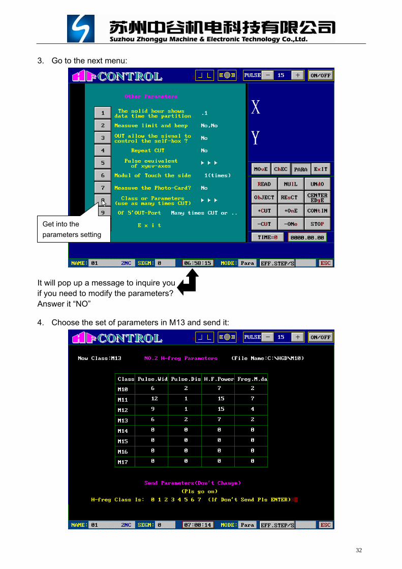
3. Go to the next menu:
It will pop up a message to inquire you if you need to modify the parameters? Answer it “NO”
4. Choose the set of parameters in M13 and send it:
Get into the
parameters setting

CNC EDM WIRE CUTTING MACHINE
PACKING LIST
WORKTABLE TRAVEL: 500×400
WORKTABLE DIMENSION: 720×460
SERIAL NUMBER:
SUZHOU ZHONGGU MACHINE & ELECTRONIC TECHNOLOGY CO., LTD
THE PEOPLES REPUBLIC OF CHINA
ZGEDM
MACHINE:
DK7740A

1 PAGE DK77 SERIES EDM WIRE CUT PACKING LIST
PAGE 1
No. ITEMS QUANTITY COMMENTS
1 Machine tool DK7740A 1 set
2 Machine foot and foot bolt 4 pairs
3 Crank for wire drum 1 set
4 Breakwater cover for wire drum 1 set
5 Wire tension adjuster 1 set
6 Clamp 1 set Installed on machine
7 Water muzzle 1 set Only for taper device
8 Vertical guage 1 set
9 Guide rollers installation tool 1 set
10 User’s manual 1 book
11 Inspection certificate 1 sheet
12 Packing list 1 sheet
13 Warranty card 1 sheet
NOTES:
PACKAGE INSPECTOR: DATE:

CNC EDM WIRE CUTTING MACHINE
WARRANTY CARD
WORKTABLE TRAVEL: 500×400
WORKTABLE DIMENSION: 720×460
SERIAL NUMBER:
Contact us:
Address: No.888 Xiangcheng District, 215131, Suzhou, China
Telephone: +86-0512-85185518 Email: [email protected]
SUZHOU ZHONGGU MACHINE & ELECTRONIC TECHNOLOGY CO., LTD
THE PEOPLES REPUBLIC OF CHINA
ZGEDM
MACHINE:
DK7740A

Suzhou Zhonggu Machine & Electronic Technology Co.,Ltd Addr: 888 Chenyang Rd, Xiangcheng District, Suzhou, China. Tel: +86-0512-85185518 FAX: +86-0512-85185515 Website: www.zgedm.com email: [email protected]
WARRANTY TERMS
1. We provide one year warranty for every machine tool.
2. Please send the warranty card to us after start machines. We will establish user’s profile
to provide you the warranty services.
3. When you face some problems of machines, regardless in or out of warranty, kindly
please contact us and tell us detailed problems, machine’s information and service
place to help us send technician to the machine as soon as possible.
4. All wear parts are not in warranty, e.g. pulleys, bearings, guides and bulbs. Users shall
buy the wear parts but no service cost during the warranty period.
5. Please take the warranty card with you when you come to us for exchanging
malfunction parts. Users shall under our instructions when change any part on the
machine themselves.
6. If problems caused by users transport the machine, add new part on the machine, not
care the machine properly or operate the machine not under instructions, we do not take
the responsibility for service free of charge even if the machine is in warranty.
7. We sell spear parts and wear parts for our machines. When you need to buy them,
please contact us and tell us what you need. We will send the parts you need after you
pay them.
8. The operators shall be trained before start the machine or maintenance. If you need
some train courses, please fill the TRAIN COURSES TABLE and send us with warranty
card.
9. When you need update machines or some special functions, please contact our sales
department. We provide maintenance and technology service over life of machines.
WARRANTY CARD OF ZGEDM (PART 1)
Serial number: Please save the part 1 in users’ hand
CUSTOMER
DEALER MACHINE
MACHINE DATE YY/MM/DD MACHINE S/N
INVOICE DATE YY/MM/DD INVOICE S/N

Suzhou Zhonggu Machine & Electronic Technology Co.,Ltd Addr: 888 Chenyang Rd, Xiangcheng District, Suzhou, China. Tel: +86-0512-85185518 FAX: +86-0512-85185515 Website: www.zgedm.com email: [email protected]
WARRANTY CARD OF ZGEDM (PART 2) Serial number: Please send part 2 to our company
CUSTOMER ADDRESS
MACHINE MACHINE S/N MACHINE DATE
DEALER INVOICE DATE INVOICE S/N
BANK ACCOUNT POST NUMBER
TELEPHONE FAX EMAIL
MANAGE DEP. OPERATE DEP. REST DAY
CUSTOMER FEEDBACK SURVEY
INSTALL RESULT:
TECHNICIAN: DATE:
CUSTOMER’S ADVICE:
CUSTOMER (SIGN): DATE:

Suzhou Zhonggu Machine & Electronic Technology Co.,Ltd Addr: 888 Chenyang Rd, Xiangcheng District, Suzhou, China. Tel: +86-0512-85185518 FAX: +86-0512-85185515 Website: www.zgedm.com email: [email protected]
SERVICE RECORDS
DATE PROBLEM SERVICE EXCHANGED
PART SERVICE RESULT
TECHNICIANCUSTOMER
SIGN COMMENTS