dm96se / dc96se - daikin comfort
TRANSCRIPT

SS-DM96SE www.daikincomfort.com 12/21Supersedes 03/20
DM96SE / DC96SE
Single-Stage, Multi-SpeedECM Gas Furnace
Up to 96% AFUEHeating Input: 40,000 –120,000 BTU/h
■ ContentsNomenclature ........................................ 2Product Specifications ........................... 3Dimensions ............................................ 5Airflow Data ........................................... 7
− DM96SE .............................................. 7 − DC96SE ............................................. 10
Wiring Diagram .................................... 14Accessories .......................................... 15
* Complete warranty details available from your local dealer or at www.daikincomfort.com. To receive the Lifetime Heat Exchanger Limited Warranty (good for as long as you own your home), the 6-Year Unit Replacement Limited Warranty and the 12-Year Parts Limited Warranty, online registration must be completed within 60 days of installation. Additional requirements for annual maintenance are required for the Unit Replacement Limited Warranty. Online registration and some of the additional requirements are not required in California or Québec.
■ Standard Features ■ Cabinet Features• Heavy-duty stainless-steel tubular heat exchanger • Stainless-steel secondary heat exchanger• Single-stage gas valve• Durable Silicon Nitride igniter• Multi-speed blower motor• Self-diagnostic control board with constant
memory fault code history output to a LED• California Low NOx emissions-compliant models available • Can no longer be installed in California's South Coast Air
Quality Management District (SCAQMD) on or after October 1, 2019.
• AHRI Certified; ETL Listed
• Designed for multi-position installation: DM96SE: upflow, horizontal left or right DC96SE: downflow, horizontal left or right
• Certified for direct vent (2-pipe) or non-direct vent (1-pipe) • Easy-to-install top venting with optional side venting• Convenient left or right connection
for gas and electrical service• Cabinet air leakage (QLeak) ≤ 2% • Heavy-gauge steel cabinet with durable finish• Fully insulated heat exchanger and blower section• Airtight solid bottom or side return with easy-cut tabs
for effortless removal in bottom air-inlet applications

2 www.daikincomfort.com SS-DM96SE SS-DM96SE www.daikincomfort.com 3
Nomenclature
D M 96 S E 060 3 B N A A
1 2 3,4 5 6 7,8,9 10 11 12 13 14
Brand Minor Revision
D -‐ Daikin Brand A -‐ Initial Release
B -‐ 1st Revision
Configuration
M -‐ Upflow/Horizontal Major Revision
C -‐ Downflow/Horizontal A -‐ Initial Release
B -‐ 1st Revision
AFUE97 – 97-‐98% AFUE 92 -‐ 92% AFUE NOx
96 – 96% AFUE N -‐ Low Nox (40ng/J)
Gas Valve Cabinet WidthM -‐ Modulating A -‐ 14"V -‐ Two Stage
S - Single Stage
B -‐ 17½"
C -‐ 21"
Motor D -‐ 24½"
C - Variable Speed ECM / CommunicatingE -‐ Multi-‐Speed ECM S - Multi-Speed PSC Maximum CFM
2 -‐ 800 CFM
MBTU/h 3 -‐ 1200 CFM
040 -‐ 40,000 BTU/h 100 -‐ 100,000 BTU/h 4 -‐ 1600 CFM
060 -‐ 60,000 BTU/h 120 -‐ 120,000 BTU/h 5 -‐ 2000 CFM
080 -‐ 80,000 BTU/h

2 www.daikincomfort.com SS-DM96SE SS-DM96SE www.daikincomfort.com 3
DM96SE 0403AN
DM96SE 0603BN
DM96SE 0803BN
DM96SE 0804CN
DM96SE 0805CN
DM96SE 1005CN
DM96SE 1205DN
Heating Data
High Fire Input¹ 40,000 60,000 80,000 80,000 80,000 100,000 120,000
High Fire Output¹ 38,440 57,660 76,880 76,880 76,880 96,100 115,320
AFUE² 96 96 96 96 96 96 96
Temperature Rise Range (°F) 25-55 35-65 35-65 25-55 25-55 30-60 35-65
Vent Diameter³ 2" - 3" 2" - 3" 2" - 3" 2" - 3" 2" - 3" 2" - 3" 3"
No. of Burners 2 3 4 4 4 5 6
Circulator Blower
Available AC @ 0.5" ESP 1.5 - 3 1.5 - 3 1.5 - 3 1.5 - 4 3 - 5 3 - 5 3 - 5
Size (D x W) 11" x 6" 11" x 8" 11" x 8" 11" x 10" 11" x 10" 11" x 10" 11" x 11"
Horsepower @ 1075 RPM ½ ½ ½ ¾ 1 1 1 No. of Speeds 5 5 5 5 5 5 5
Electrical Data
Min. Circuit Ampacity⁴ 10.3 10.3 10.3 14.1 16.93 16.93 16.93
Max. Overcurrent Device (amps)⁵ 15 15 15 15 20 20 20
Shipping Weight (lbs) 113 116 118 141 142 144 156
ENERGY STAR® Certified
1 Natural Gas BTU/h; for altitudes 0-4500' above sea level, reduce input rating by 4% for each 1000' above 4500' altitude.² DOE AFUE based upon Isolated Combustion System (ICS)³ Vent and combustion air diameters may vary depending upon vent length. Refer to the latest editions of the National Fuel Gas Code NFPA 54/ANSI Z223.1
(in the USA) and the Canada National Standard of Canada, CAN/CSA B149.1 and CAN/CSA B142.2 (in Canada).⁴ Minimum Circuit Ampacity = (1.25 x Circulator Blower Amps) + ID Blower amps.
Wire size should be determined in accordance with National Electrical Codes. Extensive wire runs will require larger wire sizes.⁵ Maximum Overcurrent Protection Device refers to maximum recommended fuse or circuit breaker size.
May use fuses or HACR-type circuit breakers of the same size as noted.
Notes• All furnaces are manufactured for use on 115 VAC, 60 Hz, single-phase electrical supply.• Gas Service Connection ½" FPT• Important: Size fuses and wires properly and make electrical connections in accordance with the National Electrical Code and/or all existing local codes.• For bottom return: Failure to unfold flanges may reduce airflow by up to 18%. This could result in performance and noise issues.
DM96SE Product Specifications

4 www.daikincomfort.com SS-DM96SE SS-DM96SE www.daikincomfort.com 5
Specifications – DC96SE
DC96SE 0403BN
DC96SE 0603BN
DC96SE 0804CN
DC96SE 1005CN
DC96SE 1205DN
Heating Data
High Fire Input¹ 40,000 60,000 80,000 100,000 120,000
High Fire Output¹ 38,440 57,660 76,880 95,000 114,000
AFUE² 96 96 96 95 95
Temperature Rise Range (°F) 35-65 35-65 40-70 40-70 45-75
Vent Diameter³ 2" - 3" 2" - 3" 2" - 3" 2" - 3" 3"
No. of Burners 2 3 4 5 6
Circulator Blower
Available AC @ 0.5" ESP 1.5 - 3 1.5 - 3 2.5 - 4 3 - 5 3 - 5
Size (D x W) 11" x 8" 11" x 8" 11" x 10" 11" x 10" 11" x 11"
Horsepower @ 1075 RPM ½ ½ ¾ 1 1
No. of Speeds 5 5 5 5 5
Filter Size (in²)
Permanent 10.3 10.3 14.05 16.93 16.93
Disposable 15 15 15 20 20
Electrical Data 113 116 141 144 156
Min. Circuit Ampacity⁴ 9.6 9.6 11.7 16.93 16.93
Max. Overcurrent Device (amps)⁵ 15 15 14.1 20 20
Shipping Weight (lbs) 111 114 139 142 154
ENERGY STAR® Certified NO NO NO NO NO
¹ Natural Gas BTU/h; for altitudes 0-4500' above sea level, reduce input rating by 4% for each 1000' above 4500' altitude.² DOE AFUE based upon Isolated Combustion System (ICS)³ Vent and combustion air diameters may vary depending upon vent length. Refer to the latest editions of the National Fuel Gas Code NFPA 54/ANSI
Z223.1 (in the USA) and the Canada⁴ Minimum Circuit Ampacity = (1.25 x Circulator Blower Amps) + ID Blower amps.
Wire size should be determined in accordance with National Electrical Codes. Extensive wire runs will require larger wire sizes.⁵ Maximum Overcurrent Protection Device refers to maximum recommended fuse or circuit breaker size.
May use fuses or HACR-type circuit breakers of the same size as noted.
Notes• All furnaces are manufactured for use on 115 VAC, 60 Hz, single-phase electrical supply.• Gas Service Connection ½" FPT• Important: Size fuses and wires properly and make electrical connections in accordance with the National Electrical Code
and/or all existing local codes.

4 www.daikincomfort.com SS-DM96SE SS-DM96SE www.daikincomfort.com 5
Minimum Clearances to Combustible Materials
Position Sides Rear Front Bottom Flue Top
Upflow 0" 0" 3" C 0" 1"
Horizontal 6" 0" 3" C 0" 6"
C = If placed on combustible floor, the floor MUST be wood ONLY.
DM96SE Dimensions
Air Discharge Air Return
Model A B C D E
DM96SE0403AN 14" 12½" 10½" 8⅝" 10⅛"
DM96SE0603BN 17½" 16" 13⅞" 12⅛" 13⅝"
DM96SE0803BN 17½" 16" 13⅞" 12⅛" 13⅝"
DM96SE0804CN 21" 19½" 17⅜" 16" 17½"
DM96SE0805CN 21" 19½" 17⅜" 16" 17½"
DM96SE1005CN 21" 19½" 17⅜" 16" 17½"
DM96SE1205DN 24½" 23" 20⅞" 19⅜" 20⅞"
59¼
19⅝
34½
¾
19½
⅞
¾
B
C
23
2⅜
1⅞
2½
2
6½
5
9¼
19⅝23
24⅞
31⅞
A
21⅛
2⅝
14
23
1½
1⅜
¾
287/8
2⅜1⅞
2½
2
2¾6½
1⅞
26½
23½Folded Flanges
22Unfolded Flanges
DUnfolded Flanges
EFolded Flanges
AirDischarge
AirDischarge
LEFT SIDE VIEW FRONT VIEW RIGHT SIDE VIEW
Condensate DrainTrap Exterior
Connection(Right or Left Side)
¾ PVC
Vent/ Flue Pipe2" PVC
Alternate Vent/ FlueLocation
Right-SideDrain Trap
Exterior Holes
High-VoltageElectrical Outlet
AlternateGas Supply
Low-VoltageElectrical Outlet
Standard Gas SupplyLocation
Center DimpleFor AlternateAir Intake Pipe3" OD Hole
Air Intake2" Pipe
Left-SideDrain Trap
Exterior Holes
High-VoltageElectrical Outlet
Low-voltageElectrical Outlet

6 www.daikincomfort.com SS-DM96SE SS-DM96SE www.daikincomfort.com 7
DC96SE Dimensions
A
34½
4⅛
11⅜
14¾
25⅛
28¾
C
6⅞ 6⅞
11⅜
14⅞
14¾
25⅛
3½ 2½
2
1⅞
2⅝
23
14
1⅜
1½
1⅝
E
DUnfolded Flanges
18⅛Unfolded Flanges
20⅛Folded Flanges
2⅝
1⅞
2½
6½
2
Front ViewRight-Side View
Low-VoltageElectrical Outlet
Alternate Gas
High-VoltageElectrical Outlet
Standard Drain TrapDrain Trap Holes
Alternate Gas Supply
Alternate Vent/
High-Voltage Electrical Outlet
Right Side ExteriorDrain Trap Holes
Low-Voltage Electrical Outlet
AirDischarge
AirDischarge
Folded Flanges
B
18¼
Minimum Clearances to Combustible Materials
Position Sides Rear Front Bottom Flue Top
Downflow 0" 0" 3" NC 0" 1"
Horizontal 6" 0" 3" C 0" 6"
C = If placed on combustible floor, the floor MUST be wood ONLY.NC = For installation on non-combustible floors only. A combustible floor sub-base must be used for installations on combustible flooring.
Air Return Air Discharge
Model A B C D E
DC96SE0403BN 17½" 14⅝" 14" 14½" 16"
DC96SE0603BN 17½" 14⅝" 14" 14½" 16"
DC96SE0804CN 21" 18⅛" 17½" 18" 19½"
DC96SE1005CN 21" 18⅛" 17½" 18" 19½"
DC96SE1205DN 24½" 21⅝" 21" 21½" 23"
6 www.daikincomfort.com SS-DM96SE SS-DM96SE www.daikincomfort.com 7
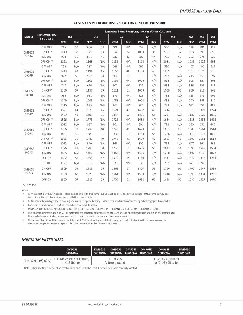
DM96SE Airflow Data
CFM & TEMPERATURE RISE VS. EXTERNAL STATIC PRESSURE
ModelDIP SWITCHES
S2-1 , S2-2
External Static Pressure, (Inches Water Column)
0.1 0.2 0.3 0.4 0.5 0.6 0.7 0.8
CFM Rise CFM Rise CFM Rise CFM Rise CFM Rise CFM CFM CFM
DM96SE 0403A
OFF OFF 715 50 666 53 609 N/A 558 N/A 500 N/A 438 386 333
ON OFF* 1110 32 1081 33 1042 34 1003 35 965 37 933 893 856
ON ON 913 39 871 41 833 43 807 44 765 46 722 675 629
OFF ON** 1191 N/A 1168 N/A 1135 N/A 1112 N/A 1081 N/A 1055 1024 998
DM96SE 0603B
OFF OFF 785 N/A 717 N/A 648 N/A 587 N/A 520 N/A 457 400 327
ON OFF* 1240 43 1194 45 1153 46 1104 48 1069 50 1019 971 929
ON ON 972 55 922 58 864 62 811 N/A 767 N/A 718 651 597
OFF ON** 1155 N/A 1105 N/A 1056 N/A 1006 N/A 958 N/A 908 857 808
DM96SE 0803B
OFF OFF 747 N/A 676 N/A 602 N/A 529 N/A 453 N/A 386 329 281
ON OFF* 1206 57 1157 59 1111 61 1059 62 1009 65 966 913 863
ON ON 985 N/A 931 N/A 875 N/A 823 N/A 782 N/A 723 673 606
OFF ON** 1149 N/A 1095 N/A 1051 N/A 1003 N/A 951 N/A 900 845 812
DM96SE 0804C
OFF OFF 1010 N/A 935 N/A 861 N/A 785 N/A 721 N/A 631 553 483
ON OFF* 1621 44 1570 45 1521 47 1467 48 1414 50 1378 1327 1274
ON ON 1439 49 1400 51 1347 53 1291 55 1234 N/A 1182 1125 1065
OFF ON** 1826 N/A 1775 N/A 1726 N/A 1684 N/A 1634 N/A 1588 1538 1492
DM96SE 0805C
OFF OFF 1012 N/A 937 N/A 861 N/A 801 N/A 722 N/A 630 552 485
ON OFF* 1836 39 1787 40 1746 41 1699 42 1653 43 1607 1561 1514
ON ON 1431 50 1389 51 1335 53 1283 55 1226 N/A 1176 1117 1055
OFF ON** 1836 39 1787 40 1746 41 1699 42 1653 43 1607 1561 1514
DM96SE 1005C
OFF OFF 1012 N/A 940 N/A 863 N/A 800 N/A 715 N/A 627 561 496
ON OFF* 1826 49 1783 50 1730 51 1685 53 1642 54 1596 1548 1504
ON ON 1465 N/A 1402 N/A 1360 N/A 1306 N/A 1250 N/A 1197 1138 1073
OFF ON 1602 55 1556 57 1510 59 1460 N/A 1411 N/A 1372 1315 1261
DM96SE 1205D
OFF OFF 1121 N/A 1018 N/A 933 N/A 839 N/A 762 N/A 671 592 519
ON OFF* 1969 54 1913 56 1862 57 1807 59 1756 61 1705 1647 1599
ON ON 1688 63 1626 N/A 1564 N/A 1500 N/A 1448 N/A 1393 1334 1267
OFF ON 1865 57 1812 59 1755 61 1692 63 1638 65 1587 1527 1476
¹ at 0.5" ESP
Notes• CFM in chart is without filter(s). Filters do not ship with this furnace, but must be provided by the installer. If the furnace requires
two return filters, this chart assumes both filters are installed.• All furnaces ship as high-speed cooling and medium-speed heating. Installer must adjust blower cooling & heating speed as needed.• For most jobs, about 400 CFM per ton when cooling is desirable.• INSTALLATION IS TO BE ADJUSTED TO OBTAIN TEMPERATURE RISE WITHIN THE RANGE SPECIFIED ON THE RATING PLATE.• This chart is for information only. For satisfactory operation, external static pressure should not exceed value shown on the rating plate.
The shaded area indicates ranges in excess of maximum static pressure allowed when heating.• The above chart is for U.S. furnaces installed at 0-2000 feet. At higher altitudes, a properly derated unit will have approximately
the same temperature rise at a particular CFM, while ESP at the CFM will be lower.
Minimum Filter Sizes
DM96SE 0403ANA
DM96SE0603BNA
DM96SE0803BNA
DM96SE0804CNA
DM96SE0805CNA
DM96SE1005CNA
DM96SE1205DNA
Filter Size (in²) (Qty)(1) 16xX 25 (side or bottom)
14 X 25 (bottom)(1) 16xX 25
(side or bottom)(1) 20 x 25 (bottom) or (2) 16 x 25 (side)
Note: Other size filters of equal or greater dimensions may be used. Filters may also be centrally located.

8 www.daikincomfort.com SS-DM96SE SS-DM96SE www.daikincomfort.com 9
CIRCULATION AIRFLOW DATA
ModelDIP SWITCHES
S2-3 , S2-4
External Static Pressure, (Inches Water Column)
0.1 0.2 0.3 0.4 0.5 0.6 0.7 0.8 0.9 1
CFM CFM CFM CFM CFM CFM CFM CFM CFM CFM
DM96SE 0403A
OFF OFF 715 666 609 558 500 438 386 333 276 220ON OFF 1110 1081 1042 1003 965 933 893 856 820 803OFF ON 1191 1168 1135 1112 1081 1055 1024 998 978 N/AON ON 1344 1312 1278 1247 1215 1178 1143 1114 1081 1049
DM96SE 0603B
OFF OFF 785 717 648 587 520 457 400 327 269 206ON OFF 1240 1194 1153 1104 1069 1019 971 929 893 N/AOFF ON 1155 1105 1056 1006 958 908 857 808 772 723ON ON 1384 1338 1300 1257 1215 1169 1125 1080 1040 994
DM96SE 0803B
OFF OFF 747 676 602 529 453 386 329 281 186 N/AON OFF 1206 1157 1111 1059 1009 966 913 863 834 784OFF ON 1149 1095 1051 1003 951 900 845 812 762 707ON ON 1414 1380 1333 1305 1260 1223 1180 1137 1091 1047
DM96SE 0804C
OFF OFF 1010 935 861 785 721 631 553 483 423 350ON OFF 1621 1570 1521 1467 1414 1378 1327 1274 1221 1167OFF ON 1826 1775 1726 1684 1634 1588 1538 1492 1448 1398ON ON 1843 1798 1753 1710 1666 1618 1574 1526 1481 1432
DM96SE 0805C
OFF OFF 1012 937 861 801 722 630 552 485 420 353ON OFF 1836 1787 1746 1699 1653 1607 1561 1514 1471 1419OFF ON 1836 1787 1746 1699 1653 1607 1561 1514 1471 1419ON ON 2215 2171 2137 2098 2060 2022 1986 1948 1908 1869
DM96SE 1005C
OFF OFF 1012 940 863 800 715 627 561 496 437 374ON OFF 1826 1783 1730 1685 1642 1596 1548 1504 1455 1406OFF ON 1602 1556 1510 1460 1411 1372 1315 1261 1207 1156ON ON 2225 2180 2141 2105 2070 2033 1996 1957 1923 1883
DM96SE 1205D
OFF OFF 1121 1018 933 839 762 671 592 519 447 371
ON OFF 1969 1913 1862 1807 1756 1705 1647 1599 1544 1481
OFF ON 1865 1812 1755 1692 1638 1587 1527 1476 1411 1351
ON ON 2268 2214 2173 2117 2068 2022 1978 1924 1874 1832
¹ at 0.5" ESP
Notes• CFM in chart is without filter(s). Filters do not ship with this furnace, but must be provided by the installer. If the furnace requires
two return filters, this chart assumes both filters are installed.• All furnaces ship as high-speed cooling and medium-speed heating. Installer must adjust blower cooling & heating speed as needed.• For most jobs, about 400 CFM per ton when cooling is desirable.• INSTALLATION IS TO BE ADJUSTED TO OBTAIN TEMPERATURE RISE WITHIN THE RANGE SPECIFIED ON THE RATING PLATE.• This chart is for information only. For satisfactory operation, external static pressure should not exceed value shown on the rating plate.
The shaded area indicates ranges in excess of maximum static pressure allowed when heating.• The above chart is for U.S. furnaces installed at 0-2000 feet. At higher altitudes, a properly derated unit will have approximately
the same temperature rise at a particular CFM, while ESP at the CFM will be lower.
DM96SE Airflow Data

8 www.daikincomfort.com SS-DM96SE SS-DM96SE www.daikincomfort.com 9
COOLING AIRFLOW DATA
ModelDIP SWITCHES
S1-1 , S1-2 , S1-3
External Static Pressure, (Inches Water Column)
0.1 0.2 0.3 0.4 0.5 0.6 0.7 0.8 0.9 1
CFM CFM CFM CFM CFM CFM CFM CFM CFM CFM
DM96SE 0403A
OFF OFF OFF 715 666 609 558 500 438 386 333 276 220OFF ON ON 715 666 609 558 500 438 386 333 276 220ON OFF ON 715 666 609 558 500 438 386 333 276 220ON ON ON 715 666 609 558 500 438 386 333 276 220
ON OFF OFF 1110 1081 1042 1003 965 933 893 856 820 803ON ON OFF 913 871 833 807 765 722 675 629 574 535OFF ON OFF 1191 1168 1135 1112 1081 1055 1024 998 978 N/AOFF OFF ON* 1344 1312 1278 1247 1215 1178 1143 1114 1081 1049
DM96SE 0603B
OFF OFF OFF 785 717 648 587 520 457 400 327 269 206OFF ON ON 785 717 648 587 520 457 400 327 269 206ON OFF ON 785 717 648 587 520 457 400 327 269 206ON ON ON 785 717 648 587 520 457 400 327 269 206
ON OFF OFF 1240 1194 1153 1104 1069 1019 971 929 893 N/AON ON OFF 972 922 864 811 767 718 651 597 556 511OFF ON OFF 1155 1105 1056 1006 958 908 857 808 772 723OFF OFF ON* 1384 1338 1300 1257 1215 1169 1125 1080 1040 994
DM96SE 0803B
OFF OFF OFF 747 676 602 529 453 386 329 281 186 N/AOFF ON ON 747 676 602 529 453 386 329 281 186 N/AON OFF ON 747 676 602 529 453 386 329 281 186 N/AON ON ON 747 676 602 529 453 386 329 281 186 N/A
ON OFF OFF 1206 1157 1111 1059 1009 966 913 863 834 784ON ON OFF 985 931 875 823 782 723 673 606 548 508OFF ON OFF 1149 1095 1051 1003 951 900 845 812 762 707OFF OFF ON* 1414 1380 1333 1305 1260 1223 1180 1137 1091 1047
DM96SE 0804C
OFF OFF OFF 1010 935 861 785 721 631 553 483 423 350OFF ON ON 1010 935 861 785 721 631 553 483 423 350ON OFF ON 1010 935 861 785 721 631 553 483 423 350ON ON ON 1010 935 861 785 721 631 553 483 423 350
ON OFF OFF 1621 1570 1521 1467 1414 1378 1327 1274 1221 1167ON ON OFF 1439 1400 1347 1291 1234 1182 1125 1065 1000 930OFF ON OFF 1826 1775 1726 1684 1634 1588 1538 1492 1448 1398OFF OFF ON* 1843 1798 1753 1710 1666 1618 1574 1526 1481 1432
DM96SE 0805C
OFF OFF OFF 1012 937 861 801 722 630 552 485 420 353OFF ON ON 1012 937 861 801 722 630 552 485 420 353ON OFF ON 1012 937 861 801 722 630 552 485 420 353ON ON ON 1012 937 861 801 722 630 552 485 420 353
ON OFF OFF 1836 1787 1746 1699 1653 1607 1561 1514 1471 1419ON ON OFF 1431 1389 1335 1283 1226 1176 1117 1055 993 924OFF ON OFF 1836 1787 1746 1699 1653 1607 1561 1514 1471 1419OFF OFF ON* 2215 2171 2137 2098 2060 2022 1986 1948 1908 1869
DM96SE 1005C
OFF OFF OFF 1012 940 863 800 715 627 561 496 437 374OFF ON ON 1012 940 863 800 715 627 561 496 437 374ON OFF ON 1012 940 863 800 715 627 561 496 437 374ON ON ON 1012 940 863 800 715 627 561 496 437 374
ON OFF OFF 1826 1783 1730 1685 1642 1596 1548 1504 1455 1406ON ON OFF 1465 1402 1360 1306 1250 1197 1138 1073 1016 947OFF ON OFF 1602 1556 1510 1460 1411 1372 1315 1261 1207 1156OFF OFF ON* 2225 2180 2141 2105 2070 2033 1996 1957 1923 1883
DM96SE 1205D
OFF OFF OFF 1121 1018 933 839 762 671 592 519 447 371OFF ON ON 1121 1018 933 839 762 671 592 519 447 371ON OFF ON 1121 1018 933 839 762 671 592 519 447 371ON ON ON 1121 1018 933 839 762 671 592 519 447 371
ON OFF OFF 1969 1913 1862 1807 1756 1705 1647 1599 1544 1481ON ON OFF 1688 1626 1564 1500 1448 1393 1334 1267 1199 1125OFF ON OFF 1865 1812 1755 1692 1638 1587 1527 1476 1411 1351OFF OFF ON* 2268 2214 2173 2117 2068 2022 1978 1924 1874 1832
DM96SE Airflow Data
See notes page 8

10 www.daikincomfort.com SS-DM96SE SS-DM96SE www.daikincomfort.com 11
DC96SE Airflow Data
CFM & TEMPERATURE RISE VS. EXTERNAL STATIC PRESSURE
ModelDIP SWITCH-ES S2-1 , S2-2
External Static Pressure, (Inches Water Column)
0.1 0.2 0.3 0.4 0.5 0.6 0.7 0.8
CFM Rise CFM Rise CFM Rise CFM Rise CFM Rise CFM CFM CFM
DC96SE 0403B
OFF OFF 629 N/A 566 N/A 509 N/A 450 N/A 388 N/A 327 269 228
ON OFF* 949 37 899 40 853 42 809 44 786 45 742 697 652
ON ON 733 49 672 53 613 N/A 563 N/A 512 N/A 454 404 349
OFF ON** 1126 N/A 1086 N/A 1044 N/A 1006 N/A 968 N/A 925 885 849
DC96SE 0603B
OFF OFF 754 N/A 684 N/A 615 N/A 542 N/A 471 N/A 411 343 276
ON OFF* 1332 40 1291 41 1252 43 1218 44 1173 45 1134 1088 1049
ON ON 972 55 922 58 864 62 811 N/A 767 N/A 718 651 597
OFF ON 1155 46 1105 48 1056 51 1006 53 958 56 908 857 808
DC96SE 0804C
OFF OFF 760 N/A 686 N/A 613 N/A 542 N/A 459 N/A 376 310 266
ON OFF* 1390 51 1342 53 1292 55 1254 57 1201 59 1157 1112 1072
ON ON 1397 51 1361 52 1318 54 1266 56 1224 58 1181 1139 1095
OFF ON** 1581 N/A 1537 N/A 1492 N/A 1452 N/A 1413 N/A 1387 1347 1305
DC96SE 1005C
OFF OFF 1211 N/A 1129 N/A 1045 N/A 964 N/A 890 N/A 812 764 702
ON OFF* 1650 54 1592 56 1530 58 1478 60 1428 62 1389 1327 1270
ON ON 1457 61 1394 64 1338 66 1294 69 1236 N/A 1171 1110 1048
OFF ON** 1860 N/A 1810 N/A 1755 N/A 1702 N/A 1656 N/A 1611 1553 1511
DC96SE 1205D
OFF OFF 1296 N/A 1190 N/A 1076 N/A 960 N/A 839 N/A 760 653 559
ON OFF* 1917 56 1843 58 1759 61 1686 63 1600 67 1513 1420 1348
ON ON 1611 66 1521 70 1433 74 1347 N/A 1246 N/A 1145 1044 953
OFF ON** 2011 N/A 1936 N/A 1858 N/A 1779 N/A 1692 N/A 1610 1531 1442
¹ at 0.5" ESP
Notes• CFM in chart is without filter(s). Filters do not ship with this furnace, but must be provided by the installer. If the furnace requires
two return filters, this chart assumes both filters are installed.• All furnaces ship as high-speed cooling and medium-speed heating. Installer must adjust blower cooling & heating speed as needed.• For most jobs, about 400 CFM per ton when cooling is desirable.• INSTALLATION IS TO BE ADJUSTED TO OBTAIN TEMPERATURE RISE WITHIN THE RANGE SPECIFIED ON THE RATING PLATE.• This chart is for information only. For satisfactory operation, external static pressure should not exceed value shown on the rating plate.
The shaded area indicates ranges in excess of maximum static pressure allowed when heating.• The above chart is for U.S. furnaces installed at 0-2000 feet. At higher altitudes, a properly derated unit will have approximately the
same temperature rise at a particular CFM, while ESP at the CFM will be lower.
Minimum Filter Sizes
DC96SE 0403BNA
DC96SE0603BNA
DC96SE0804CNA
DC96SE1005CNA
DC96SE1205DNA
Filter Size (in²) (Qty) (2) 10 x 20 or (1) 16 x 25 (top return) (1) 14 x 20 (bottom) or (1) 20 x 25 (top return)
Note: Other size filters of equal or greater dimensions may be used. Filters may also be centrally located.

10 www.daikincomfort.com SS-DM96SE SS-DM96SE www.daikincomfort.com 11
CIRCULATION AIRFLOW DATA
ModelDIP SWITCHES
S2-3 , S2-4
External Static Pressure, (Inches Water Column)
0.1 0.2 0.3 0.4 0.5 0.6 0.7 0.8 0.9 1
CFM CFM CFM CFM CFM CFM CFM CFM CFM CFM
DC96SE 0403B
OFF OFF 629 566 509 450 388 327 269 228 195 153ON OFF* 949 899 853 809 786 742 697 652 609 575ON ON 1126 1086 1044 1006 968 925 885 849 827 792
OFF ON** 1359 1321 1284 1251 1218 1181 1147 1114 1080 1045
DC96SE 0603B
OFF OFF 754 684 615 542 471 411 343 276 214 N/AON OFF* 1332 1291 1252 1218 1173 1134 1088 1049 1013 N/AON ON 1155 1105 1056 1006 958 908 857 8080 772 723
OFF ON** 1384 1338 1300 1257 1215 1189 1169 1125 1080 1040
DC96SE 0804C
OFF OFF 760 686 613 542 459 376 310 266 224 190ON OFF* 1390 1342 1292 1254 1201 1157 1112 1072 1022 985ON ON 1581 1537 1492 1452 1413 1387 1347 1305 1267 1225
OFF ON** 1800 1758 1716 1678 1636 1601 1565 1529 1491 1457
DC96SE 1005C
OFF OFF 1211 1129 1045 964 890 812 764 702 639 583ON OFF* 1650 1592 1530 1478 1428 1389 1327 1270 1213 1159ON ON 1860 1810 1755 1702 1656 1611 1553 1511 1454 1405
OFF ON** 2230 2176 2125 2086 2038 1999 1958 1917 1880 1829
DC96SE 1205D
OFF OFF 1296 1190 1076 960 839 760 653 559 452 351ON OFF* 1917 1843 1759 1686 1600 1513 1420 1348 1258 1173ON ON 2011 1936 1858 1779 1692 1610 1531 1442 1365 1266
OFF ON** 2317 2257 2196 2122 2061 1990 1914 1762 1523 1232¹ at 0.5" ESP
Notes• CFM in chart is without filter(s). Filters do not ship with this furnace, but must be provided by the installer. If the furnace requires
two return filters, this chart assumes both filters are installed.• All furnaces ship as high-speed cooling and medium-speed heating. Installer must adjust blower cooling & heating speed as needed.• For most jobs, about 400 CFM per ton when cooling is desirable.• INSTALLATION IS TO BE ADJUSTED TO OBTAIN TEMPERATURE RISE WITHIN THE RANGE SPECIFIED ON THE RATING PLATE.• This chart is for information only. For satisfactory operation, external static pressure should not exceed value shown on the rating plate.
The shaded area indicates ranges in excess of maximum static pressure allowed when heating.• The above chart is for U.S. furnaces installed at 0-2000 feet. At higher altitudes, a properly derated unit will have approximately
the same temperature rise at a particular CFM, while ESP at the CFM will be lower.
DC96SE Airflow Data

12 www.daikincomfort.com SS-DM96SE SS-DM96SE www.daikincomfort.com 13
COOLING AIRFLOW DATA
ModelDIP SWITCHES
S1-1 , S1-2 , S1-3
External Static Pressure, (Inches Water Column)
0.1 0.2 0.3 0.4 0.5 0.6 0.7 0.8 0.9 1
CFM CFM CFM CFM CFM CFM CFM CFM CFM CFM
DC96SE 0403B
OFF OFF OFF 629 566 509 450 388 327 269 228 195 153OFF ON ON 629 566 509 450 388 327 269 228 195 153ON OFF ON 629 566 509 450 388 327 269 228 195 153ON ON ON 629 566 509 450 388 327 269 228 195 153
ON OFF OFF 949 899 853 809 786 742 697 652 609 575ON ON OFF 733 672 613 563 512 454 404 349 306 261OFF ON OFF 1126 1086 1044 1006 968 925 885 849 827 792OFF OFF ON* 1359 1321 1284 1251 1218 1181 1147 1114 1080 1045
DC96SE 0603B
OFF OFF OFF 754 684 615 542 471 411 343 276 214 N/AOFF ON ON 754 684 615 542 471 411 343 276 214 N/AON OFF ON 754 684 615 542 471 411 343 276 214 N/AON ON ON 754 684 615 542 471 411 343 276 214 N/A
ON OFF OFF 1332 1291 1252 1218 1173 1134 1088 1049 1013 N/AON ON OFF 972 922 864 811 767 718 651 597 556 511OFF ON OFF 1155 1105 1056 1006 958 908 857 808 772 723OFF OFF ON* 1384 1338 1300 1257 1215 1189 1169 1125 1080 1040
DC96SE 0804C
OFF OFF OFF 760 686 613 542 459 376 310 266 224 190OFF ON ON 760 686 613 542 459 376 310 266 224 190ON OFF ON 760 686 613 542 459 376 310 266 224 190ON ON ON 760 686 613 542 459 376 310 266 224 190
ON OFF OFF 1390 1342 1292 1254 1201 1157 1112 1072 1022 985ON ON OFF 1397 1361 1318 1266 1224 1181 1139 1095 1050 1003OFF ON OFF 1581 1537 1492 1452 1413 1387 1347 1305 1267 1225OFF OFF ON* 1800 1758 1716 1678 1636 1601 1565 1529 1491 1457
DC96SE 1005C
OFF OFF OFF 1211 1129 1045 964 890 812 764 702 639 583OFF ON ON 1211 1129 1045 964 890 812 764 702 639 583ON OFF ON 1211 1129 1045 964 890 812 764 702 639 583ON ON ON 1211 1129 1045 964 890 812 764 702 639 583
ON OFF OFF 1650 1592 1530 1478 1428 1389 1327 1270 1213 1159ON ON OFF 1457 1394 1338 1294 1236 1171 1110 1048 986 919OFF ON OFF 1860 1810 1755 1702 1656 1611 1553 1511 1454 1405OFF OFF ON* 2230 2176 2125 2086 2038 1999 1958 1917 1880 1829
DC96SE 1205D
OFF OFF OFF 1296 1190 1076 960 839 760 653 559 452 351OFF ON ON 1296 1190 1076 960 839 760 653 559 452 351ON OFF ON 1296 1190 1076 960 839 760 653 559 452 351ON ON ON 1296 1190 1076 960 839 760 653 559 452 351
ON OFF OFF 1917 1843 1759 1686 1600 1513 1420 1348 1258 1173ON ON OFF 1611 1521 1433 1347 1246 1145 1044 953 876 790OFF ON OFF 2011 1936 1858 1779 1692 1610 1531 1442 1365 1266OFF OFF ON* 2317 2257 2196 2122 2061 1990 1914 1762 1523 1232

12 www.daikincomfort.com SS-DM96SE SS-DM96SE www.daikincomfort.com 13
Temperature Rise Range Chart
3040
5060
7080
9011
012
010
013
014
015
0
100
90 80 70 60 50 40 30 20 10
OU
TPU
TB
TU/H
Rx
1000
BTU
OU
TPU
Tvs
TEM
PE
RAT
UR
ER
ISE
CH
AR
TTEMPERATURERISE
600
CFM
700
900 10
00 1100 12
00
1400
1600 18
00 2000 22
00 2400
CFM
FOR
MU
LAS
BTU
OU
TPU
T=
CFM
x1.
08x
RIS
E
RIS
E=
BTU
OU
TPU
T1.
08÷
CFM
800
Temperature Rise
Ou
tpu
t BT
U/h
x 1
,000
Form
ulas
BTU
/h O
utpu
t = C
FM x
1.0
8 x
Rise
Rise
=
BTU
/H O
utpu
t
CFM
x 1
.08
BTU
Ou
tpu
t Vs
. Tem
pera
ture
Ris
e Ch
art

14 www.daikincomfort.com SS-DM96SE SS-DM96SE www.daikincomfort.com 15
Wiring Diagram
Wiri
ng i
s su
bjec
t to
cha
nge.
Alw
ays
refe
r to
the
wiri
ng d
iagr
am o
n th
e un
it fo
r th
e m
ost
up-t
o-da
te w
iring
.⚠
War
ning
Hig
h Vo
ltage
: D
isco
nnec
t al
l po
wer
bef
ore
serv
icin
g or
ins
talli
ng t
his
unit.
Mul
tiple
pow
er
sour
ces
may
be
pres
ent.
Failu
re to
do
so m
ay c
ause
pro
pert
y da
mag
e, p
erso
nal i
njur
y, o
r de
ath.⚡
YL YELLOWOR ORANGEPU PURPLEGR GREENBK BLACK
BR BROWNWH WHITEBL BLUEGY GRAYRD RED
COLOR CODES:
LOW VOLTAGE (24V)
LOW VOLTAGE FIELD
HI VOLTAGE (115V)
HI VOLTAGE FIELDNOTES:1. SET HEAT ANTICIPATOR ON ROOM THERMOSTAT AT 0.7 AMPS.2. MANUFACTUR'S SPECIFIED REPLACEMENT PARTS MUST BE USED WHEN SERVICING.
GAS VALVE
C2
INTERNAL TOINTEGRATED CONTROL
JUNCTION
EQUIPMENT GND
FIELD GND
DIAGNOSTICLED
2 CIRCUITCONNECTOR
HOTSURFACEIGNITER
OVERCURRENTPROT. DEVICE
IGNITER
TH (3)
INTEGRATEDCONTROL MODULE
JUNCTION BOX
LINE-H
XFMR-H
INTEGRATED CONTROL MODULE
INTEGRATED CONTROL MODULE
GND
DISCONNECT
L N
DISCONNECT POWERBEFORE SERVICING.WIRING TO UNITMUST BEPROPERLYPOLARIZEDAND GROUNDED.
OVERCURRENT PROTECTION DEVICE
BL
4. BLOWER SPEEDS SHOULD BE ADJUSTED BY INSTALLER TO MATCH THE INSTALLATION REQUIREMENTS SOAS TO PROVIDE THE CORRECT HEATING TEMPERATURE RISE AND THE CORRECT COOLING CFM.
3. IF ANY OF THE ORIGINAL WIRE AS SUPPLIED WITH THE FURNACE MUST BE REPLACED, IT MUST BEHAVING A TEMPERATURE RATING OF AT LEAST
TERMINAL
SWITCH (PRESS.)
5. UNIT MUST BE PERMANENTLY GROUNDED AND CONFORM TO N.E.C. AND LOCAL CODES.
PK PINK
FLAMESENSOR
( SINGLE CONTROL ON 40K BTU )
BK
PLUG CONNECTION
FIELD SPLICE
SWITCH (TEMP.)
BLOWERCOMPARTMENTDOOR SWITCH(OPEN WHENDOOR OPEN)
DOORSWITCH
WARNING:DISCONNECT POWER BEFORESERVICING.WIRING TO UNIT MUST BEPROPERLY POLARIZED AND GROUNDED.
POWER SUPPLY WITHOVERCURRENT PROTECTIONDEVICE
1
TO 115 VAC / 1Ø / 60HZ
OR
ID BLOWERPRESSURESWITCH
RD
WH
BURNER COMPARTMENT
BLOWER COMPARTMENT
NO
YL
CONTROLPRIMARY LIMITAUTO RESET
BL
PU
MANUAL RESET ROLLOUT LIMIT CONTROL(S)
RD
OR
PK
BK
WH WH
BLOWERINDUCED DRAFT
AUXILIARYLIMITCONTROLS
C
FS
LIMIT CONTROLSAUXILIARY
IGNITERHOT SURFACE
IND
IGN
BLWRCIRCULATOR
BLWRID
FLAME SENSOR
115 VAC
TRANSFORMER40 VA
24 VAC
GND
CONTROLLIMITPRIMARYAUTO RESET
(SINGLE CONTROL ON 40K BTU)LIMIT CONTROL(S)MANUAL RESET ROLLOUT
RO1 (5)
RO2 (11)
HLO (1)
HLI (7)
MVC (9)GND (8)
TR (6)
OR
WH
BL
YLOR
RDGR
BR
PK
PK
BK
BK
24V THERMOSTAT CONNECTIONS N.E.C. CLASS 2 WIRE
MICROTO
C
G
Y
W
R
2
OR
BLYL
OR
PK
RD
OR
WH
XFMR-H
BL
GY
GR
123
12 11 10
9 8 7
6 5 4
WARNING:
105°C. USE COPPER CONDUCTORS ONLY.
PSO (4)
MV(12)
PS (10) C NO
ID BLOWERPRESSURESWITCH
0
C
6
5
4
3
2
1
OFF = CONTROL FAILURESTEADY ON = NORMAL OPERATION
1 FLASH =2 FLASHES = PRESSURE SWITCH STUCK CLOSED3 FLASHES = PRESSURE SWITCH STUCK OPEN4 FLASHES = OPEN HIGH LIMIT5 FLASHES = FLAME SENSE WITHOUT GAS VALVE
OPEN ROLLOUT6 FLASHES =
SYSTEM LOCKOUT (RETRIES EXCEEDED)
CONTINUOUS/RAPID FLASHES = REVERSED 115 VAC POLARITY
CONTROLMODULE
INTEGRATED
FUSE
MI GY
GY
M1
GASVALVE
C2
TO 115VAC/ 1 Ø /60 HZ POWER SUPPLY WITH
PU
BR
GY
BR
LINE NEUTRALS
NO C
FRONT COVERPRESSURE SWITCH
C
NO
FRONT COVERPRESSURE SWITCH
YL
7 FLASHES =8 FLASHES =
LOW FLAME SIGNALIGNITER RELAY FAULT
7
8
ELECTRONICAIR CLEANEREAC-H
HUMIDIFIER
HUMIDIFIER
RC G W Y
24V THERMOSTATCONNECTIONS
N.E.C. CLASS 2 WIRE RD
OR
115 VAC
24 VAC
BK
GY
40 VATRANSFORMER
WH
GR
GND
RD
5
21
43
G
C
WH
L
N
BLOWERCIRCULATOR
HARNESSECM MTR
RDBK
ORBL
BK
RD
WH
WH
WH
BLRD
OR
BK
WH
BK
GND
DISCONNECTL
NWH
JUNCTION BOX
GND
GR
GR
GND
GND
E9
E36IG N-N
IG N-N
IG N-NE8
120VE7HUM-N
E6IG N-N
E5XFMR-N
IGN-NE4
E32E25E3E1 E2LINE-H XFMR-H CIRC-H 120V
HUM-H EAC-H T1 T2 T3 T4 X COM
BK
R C
MICROCONTROLLED
0140F02509-A
9 FLASHES =9
10 FLASHES =10
11 FLASHES =11
12 FLASHES =12
REPLACED WITH WIRING MATERIAL
TWINNING FAULTOPEN FUSEIGNITER OPENINDUCER RELAY ERROR / IMPROPER GROUNDING
BKCIRC-H

14 www.daikincomfort.com SS-DM96SE SS-DM96SE www.daikincomfort.com 15
Accessories – DM96SE / DC96SE
Model Description DC96SE 0403BN
DC96SE 0603BN
DC96SE 0804CN
DC96SE 1005CN
DC96SE 1205DN
72950 Concentric Vent Kit (2") √ √ √ √ ---
72951 Concentric Vent Kit (3") √ √ √ √ √
CFSB17 Downflow Sub-Base 17.5" √ √ --- --- ---
CFSB21 Downflow Sub-Base 21" ― --- √ √ ---
CFSB24 Downflow Sub-Base 24" ― --- --- --- √
RF000142 Drain Kit -Horizontal Left Vertical Flue √ --- --- --- ---
EFR02External Filter Rack with 16"x25" Permanent Filter √ √ √ --- ---
0170K00000S Flush Mount Vent Kit - 3" or 2" √ √ √ √ √
0170K00001S Flush Mount Vent Kit - 2" √ √ √ √ ---
AFE18-60A Fossil Fuel (Dual Fuel) Kit √ √ √ √ √
HASFK High-Altitude Natural Gas Kit HASFK-4 HASFK-4 HASFK-4 HASFK-4 HASFK-4
HASFK High-Altitude LP Gas Kit HASFK-5 HASFK-5 HASFK-5 HASFK-4 HASFK-4
0270F05405 Horizontal Drain Tubing Kit √ √ √ √ √
LPLP03 Low LP Gas Pressure Switch √ √ √ √ √
LPM-07 LP Conversion Kits √ √ √ √ √
Notes √ Indicates available for this model ² Indicates 9,001' to 11,000' altitude¹ Indicates 7,001' to 9,000' altitude ³ Indicates 7,001' to 11,000' altitude• All installations above 7,000' require a pressure switch change.• For installation in Canada, gas furnaces are certified only to 4,500'.
Model Description DM96SE 0403AN
DM96SE 0603BN
DM96SE 0803BN
DM96SE 0804CN
DM96SE 0805CNA
DM96SE 1005CN
DM96SE 1205DN
72950 Concentric Vent Kit (2") √ √ √ √ √ √ ―
72951 Concentric Vent Kit (3") √ √ √ √ √ √ √
RF000142 Drain Kit Horizontal Left Vertical Flue √ √ √ √ √ √ √
EFR02External Filter Rack with 16"x25" Permanent Filter √ √ √ √ ― ― ―
0170K00000S Flush Mount Vent Kit - 3" or 2" √ √ √ √ √ √ √
0170K00001S Flush Mount Vent Kit - 2" √ √ √ √ √ √ ―
AFE18-60A Fossil Fuel (Dual Fuel) Kit √ √ √ √ √ √ √
HASFK High-Altitude Natural Gas Kit TBD HASFK-4 HASFK-4 HASFK-4 HASFK-4 HASFK-4 HASFK-4
HASFK High-Altitude LP Gas Kit TBD HASFK-6 HASFK-6 HASFK-6 HASFK-5 HASFK-5 HASFK-5
0270F05404 Horizontal Drain Tubing Kit √ √ √ √ √ √ √
LPLP03 Low LP Gas Pressure Switch √ √ √ √ √ √ √
LPM-07 LP Conversion Kits √ √ √ √ √ √ √
16 www.daikincomfort.com SS-DM96SE SS-DM96SE www.daikincomfort.com PB
Our continuing commitment to quality products may mean a change in specifications without notice. ©2021 • Houston, Texas
Notes