dmr system planner
TRANSCRIPT
DMR System Planner

Copyright Information
Hytera is the trademark or registered trademark of Hytera Communications Co., Ltd. (the Company) in PRC and/or other countries or areas. The Company retains the ownership of its trademarks and product names. All other trademarks and/or product names that may be used in this manual are properties of their respective owners.
The product described in this manual may include the Company’s computer programs stored in memory or other media. Laws in PRC and/or other countries or areas protect the exclusive rights of the Company with respect to its computer programs. The purchase of this product shall not be deemed to grant, either directly or by implication, any rights to the purchaser regarding the Company’s computer programs. Any of the Company’s computer programs may not be copied, modified, distributed, decompiled, or reverse-engineered in any manner without the prior written consent of the Company.
Disclaimer
The Company endeavors to achieve the accuracy and completeness of this manual, but no warranty of accuracy or reliability is given. All the specifications and designs are subject to change without notice due to continuous technology development. No part of this manual may be copied, modified, translated, or distributed in any manner without the express written permission of us.
If you have any suggestions or would like to learn more details, please visit our website at: http://www.hytera.com.
Software Version
All the features in the system planner is based on R5.0 or above.

Revision History Version Date Description Remarks
R1.0 November 21, 2012 Initial release
1
Contents
1 DMR Introduction................................................................................................ 5
1.1 Analog Communication VS Digital Communication......................................... 6
1.2 Hytera DMR Technology Introduction.............................................................. 7
1.3 Hytera DMR Technology Highlights................................................................. 8
2 Brief Introduction of DMR Functions ................................................................... 9
2.1 Basic Parameter Introduction .......................................................................... 9
2.2 Voice Services................................................................................................11
2.2.1 Group Call ......................................................................................................11
2.2.2 Private Call .....................................................................................................11
2.2.3 All Call ........................................................................................................... 12
2.2.4 Phone............................................................................................................ 12
2.3 Data Service.................................................................................................. 16
2.3.1 Text Message ................................................................................................ 16
2.3.2 GPS............................................................................................................... 17
2.4 General Services........................................................................................... 18
2.4.1 Supplementary Service ................................................................................. 18
2.4.2 One Touch Call.............................................................................................. 20
2.4.3 Encrypt .......................................................................................................... 21
2.4.4 Telemetry....................................................................................................... 24
2.4.5 VOX............................................................................................................... 28
2.5 Emergency Alarm.......................................................................................... 30
2.5.1 Alarm............................................................................................................. 31
2.5.2 Emergency Call ............................................................................................. 32
2.5.3 Alarm with Call .............................................................................................. 32
2.5.4 Lone Worker.................................................................................................. 33
2.5.5 Man Down ..................................................................................................... 34
Hytera DMR System Planner
2
2.6 Scan.............................................................................................................. 36
2.6.1 Scan List ....................................................................................................... 38
2.6.2 Scan Stay Condition ...................................................................................... 39
2.6.3 Channel Scan Order...................................................................................... 40
2.7 Roaming........................................................................................................ 43
2.7.1 Roaming Methods ......................................................................................... 44
2.7.2 Configuring the RSSI Threshold.................................................................... 47
2.7.3 Setting Beacon Duration and Beacon Interval............................................... 51
2.7.4 Performance while Roaming ......................................................................... 54
2.8 Hytera Patented Features ............................................................................. 55
2.8.1 Pseudo Trunk ................................................................................................ 55
2.8.2 Priority Interrupt............................................................................................. 62
2.9 Analog function ............................................................................................. 72
2.10 Back-to-Back................................................................................................. 74
2.10.1 Mobile Radio Accessory Pin ...................................................................... 74
2.10.2 Repeater Accessory Pin ............................................................................ 75
2.11 Hytera DMR Application Protocol .................................................................. 77
2.11.1 Radio Registration Service (RRS) ............................................................. 78
2.11.2 Positioning System(LP)......................................................................... 80
2.11.3 Radio Control Service(RCP) ................................................................. 82
2.11.4 Text Message Service (TMP)..................................................................... 83
2.11.5 Data Transmission Service (DTP).............................................................. 84
2.11.6 Telemetry Service (TMP) ........................................................................... 85
2.11.7 Real-time Transport Service (RTP)............................................................ 86
3 Components of DMR System ........................................................................... 87
3.1 Portable Radio............................................................................................... 88
3.1.1 Product Overview.......................................................................................... 89
3.1.2 Basic Operations........................................................................................... 92
3.2 Mobile Radio ................................................................................................. 95
3.2.1 Product Overview.......................................................................................... 96

Hytera DMR System Planner
3
3.2.2 Basic Operations........................................................................................... 99
3.3 Repeater ..................................................................................................... 103
3.3.1 Introduction ................................................................................................. 104
3.3.2 Basic Operations......................................................................................... 106
3.4 RDAC (Repeater Diagnostics and Control) ..................................................110
3.4.1 Diagnose ......................................................................................................111
3.4.2 Control..........................................................................................................112
3.4.3 Repeater Configuration ................................................................................113
4 DMR System Topologies..................................................................................117
4.1 Direct Mode..................................................................................................118
4.1.1 Back-to-Back Mobile Radio Application in Direct Mode................................119
4.1.2 Further Development Functions in Direct Mode .......................................... 123
4.1.3 Telemetry..................................................................................................... 124
4.2 Repeater Mode ........................................................................................... 127
4.2.1 Back-to-back Repeaters.............................................................................. 128
4.2.2 Radio Dispatch............................................................................................ 133
4.2.3 Telemetry..................................................................................................... 133
4.3 IP Multi-site ................................................................................................. 135
4.3.1 Network Topology of IP Multi-site Connect .................................................. 137
4.3.2 Local Area Network ..................................................................................... 137
4.3.3 Wide Area Network (WAN) .......................................................................... 138
4.3.4 WAN and LAN............................................................................................. 140
4.3.5 Broadband Wireless Access........................................................................ 141
4.3.6 Digital Functions Supported in IP Multi-site Connect Mode......................... 146
4.4 Access Management................................................................................... 147
4.4.1 Local Access Management ......................................................................... 148
4.4.2 Multi-site Access Management.................................................................... 149
4.5 Repeat request priority ................................................................................ 152
4.6 Super Master............................................................................................... 152
4.6.1 Star Network Architecture............................................................................ 153
Hytera DMR System Planner
4
4.6.2 Double-layer Network Architecture.............................................................. 154
4.7 Phone Interconnect ..................................................................................... 155
4.7.1 Phone Applications in Local Mode .............................................................. 155
4.7.2 Phone Applications in IP Multi-site Connect Mode ...................................... 158
5 DMR System Considerations.......................................................................... 159
5.1 Important notes of R4.0 update................................................................... 159
5.1.1 Subscriber ................................................................................................... 159
5.1.2 Repeater ..................................................................................................... 159
5.1.3 Interaction between Subscriber and Repeater ............................................ 160
5.2 Important notes of R4.5 update................................................................... 160
5.2.1 Subscriber ................................................................................................... 160
5.2.2 Repeater ..................................................................................................... 160
5.2.3 Interaction between Subscriber and Repeater ............................................ 160
5.3 Function interaction..................................................................................... 161
5.3.1 Phone Interconnect ..................................................................................... 161
5.3.2 Encryption ................................................................................................... 162
5.3.3 Pseudo Trunking ......................................................................................... 162
5.3.4 Priority Interrupt........................................................................................... 163
5.3.5 Roaming...................................................................................................... 165
5.3.6 IP Multi-site Connect ................................................................................... 166
5.3.7 Telemetry..................................................................................................... 169
6 DMR System Documentation and Applications............................................... 171
6.1 Documentation ............................................................................................ 171
6.2 CPS............................................................................................................. 172
6.3 Tuner........................................................................................................... 173
A. Appendix......................................................................................................... 175
A.1 Abbreviation ................................................................................................ 175
A.2 Hytera Official Website................................................................................ 176

5
1 DMR Introduction
This chapter mainly introduces the Digital Mobile Radio (DMR) standards, focusing on the protocol principles and tendency of the digital technology.
DMR is an open digital radio standard for professional mobile radio users published by the European Telecommunications Standards Institute (ETSI) in 2004. This standard aims to achieve a high-efficient professional wireless communication system with less complexity and low cost.
DMR standard covers three tiers:
Tier I: This tier is for license-free use in the 446MHz band. It utilizes 6.25kHz FDMA technology, targeted at the business market. Updated recently, Tier I supports trunking system and becomes available for the professional market.
Tier II: This tier is for conventional communication. It adopts two-slot 12.5kHz TDMA technology and targets the professional market.
Tier III: This tier is for trunking and simulcast communication. Besides two-slot 12.5kHz TDMA technology, it also supports network management applications. This tier is targeted at professional market.
Digital technology presents a predictable tendency of the wireless communication, which delivers products of better communication quality, higher security, more spectrum resource and richer functions compared with analog products.
Hytera adopts the DMR technology and develops the digital radio compatible with analog work mode. Hytera DMR radios can convert analog signals into digital signals, and transmits both data and voice. Digital signals can be enhanced via the gain and transmitted in a wider coverage. Based on TDMA technology, digital radios accommodate much more subscribers.
Hytera DMR System Planner
6
1.1 Analog Communication VS Digital
Communication
Analog communication has poor privacy protection. The signal transmitted by an analog radio can be received by any other analog radio on the same channel. Thus interference easily occurs in analog communication. However, digital communication employs some technologies such as color code, which significantly enhance the interference resistance.
In analog communication, the signal becomes weakened gradually, and thus affects the coverage. In digital communication, however, the signal can be encrypted and transmitted in a wider coverage. Signal interference also has a great impact on the communication coverage: the more the signal interference occurs, the smaller the coverage becomes.
In analog communication, the transmitting radio transmits on a specified channel and the receiving radio has to receive the signals on the same channel. In digital communication, the TDMA technology allows to divide the 12.5kHz channel into two slots, which can serve as an independent channel. The transmitting radio transmits on one slot (while the other slot stays idle), and the receiving radio detects the signaling on both slots and receives signal on the active slot.
In analog communication, the FDMA technology allows multiple subscribers simultaneously access a channel. However, with TDMA technology, one 12.5kHz channel is divided into two 6.25kHz slots, and thus the spectrum resource is expanded; moreover, the RF performance remains the same even though the channel is divided. Compared with analog products, DMR products can accommodate more subscribers and thus increases the system scope.
Hytera DMR System Planner
7
1.2 Hytera DMR Technology Introduction
Hytera adopts the DMR technology and makes developments in compliance with the ETSI DMR Tier II standards.
Hytera DMR radio collects the audio signals at the microphone, converts the audio signals to analog signals, and then converts the analog signals to digital signals. In addition, the sampling signal should be strong enough to ensure high audio quality, so certain techniques are required to compress the signal.
After sampling, the radio processes the signal through coding technology, to filter the unwanted noises and make signal compression.
The encoded signal (audio or data) is then transmitted in frames. The signal with signaling can generate a digital data packet, which consists of the header (mainly the control and air interface information) and payload (encoded audio or data) and can be transferred over IP network. The header information repeats periodically during transmission, which makes the signal more reliable and realizes the late entry function.
The framing signal gets encoded for FM transmission. The bits contained in the digital packets are encoded as symbols representing the amplitude and phase of the modulated carrier frequency. Finally, the signal gets amplified and then transmitted.

Hytera DMR System Planner
8
1.3 Hytera DMR Technology Highlights
Hytera DMR technology has many advantages compared with analog technology, especially in aspects such as spectrum resource, capacity, coverage and encryption.
The DMR technology divides one channel into two alternative slots, and thus allows twice the channels based on the same spectrum resource. This is a big help to relieve the stress of increasing shortage in spectrum resource. The 2-slot technology doubles the repeater functions, which greatly reduces the cost and minimizes the configuration complexity. Furthermore, its compatibility with analog mode makes the transition cost-effective and smooth. The radio transmits on the two slots alternatively, which can reduce the transmission time length and thus ensure a longer endurance.
With Hytera DMR radios, it becomes possible to use two slots simultaneously. For example, you can receive audio and data simultaneously on both slots, or transmit audio on one slot while receive signaling to realize special functions, such as Priority Interrupt, on the other slot. The audio transmission will not be affected by data reception. In this way, users can experience a more efficient and swift communication.
With DMR technology, the communication has a larger coverage and better reliability. Analog signal is transmitted in sine waveform which may be subject to more interference; while digital signal is transmitted in rectangular waveform that can be optimized easily. In addition, digital signals can be transmitted very far by either repeater or IP network. However, analog signal cannot be sent through IP network.
During analog transmission, the signal can be received once the frequency is known, and it can be decrypted easily even scrambler is applied. This is far from enough for users who require reliable security. However, the digital signal can be encrypted through special mechanisms, in which keys are applied to make the signal inaccessible to anyone except those possessing the same key, so as to achieve communication privacy.

9
2 Brief Introduction of DMR Functions DMR digital communications system realizes voice services (such as group call, private call, all call, etc.), data services (such as text message, GPS data, ect.) and supplement services.
This chapter mainly introduces some basic functions and their parameter configurations of DMR conventional system.
2.1 Basic Parameter Introduction
DMR configurations involve some basic parameters which determine the basic attributes of DMR equipment.
The main parameters are as follows:
Radio ID: The unique identification information of each radio. You must designate an ID to the radio for other users to identify it when making a private call or sending messages. The private call ID is the Radio ID.
Group Call ID: Used to identify a particular group. The group members must define the group call ID, or they cannot receive the corresponding call.
Alias: The alias of a radio, private call contact and group call contact. It is configurable for you so that it is more convenient to find the contact to call.
Channel: The channel provides communication services using the DMR digital signaling. There is at least 1 digital channel and at most 1,023 digital channels that can be established.
Color Code: This is used to identify a system. Users who wish to communicate with each other in the same system are assigned with the same color code. A radio ignores the channel activity which does not match the preset color code in this field, as it is assuming the activity belongs to other system. In case that there are multiple systems to be monitored, then different color codes must be assigned to the corresponding channels. Range of the color code: 0 – 15.
Tx/Rx Frequency: The Tx/Rx frequency of the current channel. Both the frequencies of the communicating parties must be matched.
Tx Admit: This is used to control the Tx authority of the radio. The administrator can authorize different levels of users to different Tx rights: the low level users can be authorized to Channel Free or Color Code Free; as for the high level ones, they are set to Always Allow.
Hytera DMR System Planner
10
Tx Admit: This is used to prevents you from transmitting on channels that are already in use.
Always Allow: The radio can transmit via the PTT key any time regardless of the channel.
Channel Free: The radio is allowed to transmit when the channel is free. Code Color Free: The radio can transmit only when the channel is free or the
color code is not matched.
Group Call Hang Time: The time in which the radio still hangs in the group call after the call is over. In other words, a member's PTT operation can call back the group directly without contact list selection.
Private Call Hang Time: The time in which the radio still hangs in the private call after the call is over. Within this period, either of the communication parties can call back the other directly by holding the PTT key without contact list selection or Acknowledge.
Time Slot: DMR applies TDMA scheme to divide the 12.5kHz channel into two consecutive slots. Either slot can be used for communication or data transmission.
Slot 1: Slot 1 is used for transmitting and receiving in Repeater mode, as well as receiving signals from repeater in Direct mode.
Slot 2: Slot 2 is used for transmitting and receiving in Repeater mode, as well as receiving signals from repeater in Direct mode.
Pseudo Trunk: Both slots can be used simultaneously for communication or data transfer in Direct and Repeater modes. And in Repeater mode, the slot is alternative.
Note: Pseudo Trunk is one of the Hytera patents. Generally, in Repeater mode, DMR standard protocol defines radios to transmit in the fixed slot. If the slot is occupied, the radio has to wait for it instead of another free slot, wasting the frequency band resources. However, the Pseudo Trunk feature allows two different calls to be made simultaneously in Direct mode, as well as the dynamic slot distribution in Repeater mode. This brings great convenience and efficiency to the communications.

Hytera DMR System Planner
11
2.2 Voice Services
DMR voice services support group call, private call and all call. It means that you can make a call with a group, a person and all users in the system.
2.2.1 Group Call
A group call is transmitted to a group by a user. Each member in the group can hear the others. The configuration of the group call contacts via the CPS is prior to make a group call. After the configuration, you can make a group call by holding down PTT. All the group members must be in the same slot on the same channel, and have the matched Tx and Rx frequency and color code.
Parameter Configuration
The radio can only receive the group calls from the groups included in the Rx Group List. Thus, to receive a group call, the available groups must be added into the Rx Group List via the CPS. To make a group call, there must be available group members in the contact list. In addition, the group call ID must be set.
Group Call Hang Time: Within this period, the group members can hold down PTT to call any time without selecting the group from the contact list.
Tx Admit: The group call making radio shall not be set to “Rx Only”. Also, it must be authorized to transmit group call prior to the call making.
Temporary Group Call
A user out of the group can make a temporary group call by the keypad, but such calls will not be recorded into the call logs. In the temporary group call hang time, the members can call back.
2.2.2 Private Call
A private call is made between two individual radios only. Both parties must be in the same slot on the same channel and have the matched Tx and Rx frequency and color code.
To make a private call, the radio must be designated with an ID. Then the call maker will need to select the ID or alias of the called party to make a call.
Parameter Configuration
The ID of both the calling party and the called party must be configured before the

Hytera DMR System Planner
12
call making. You may add the ID or alias of the contacts into the contact list via the CPS or the radio menu. Even if you do not add the ID or alias, you can also enter the call ID of a contact for calling.
Private Call Hang Time: Within this period, both parties can hold down PTT to talk without selecting the other again.
Tx Admit: The private call making radio shall not be set to “Rx Only”. Also, it must be authorized to transmit private call prior to the call making.
2.2.3 All Call
All Call is a call from an individual radio to all radios in the system. All Calls do not communicate through special time slots or channels within the system. Only the user with the high authority can make an all call. This is especially significant when you need to communicate with all users in the entire channel. Both parties must be in the same slot on the same channel and have the matched Tx and Rx frequency and color code.
The all call maker must be authorized first via the CPS.
Parameter Configuration
Call ID value: 16777215 (not editable), An all call user should be with high authority. The system administrator needs to set the all call user based on actual requirements.
Tx Admit: The all call making radio shall not be set to “Rx Only”.
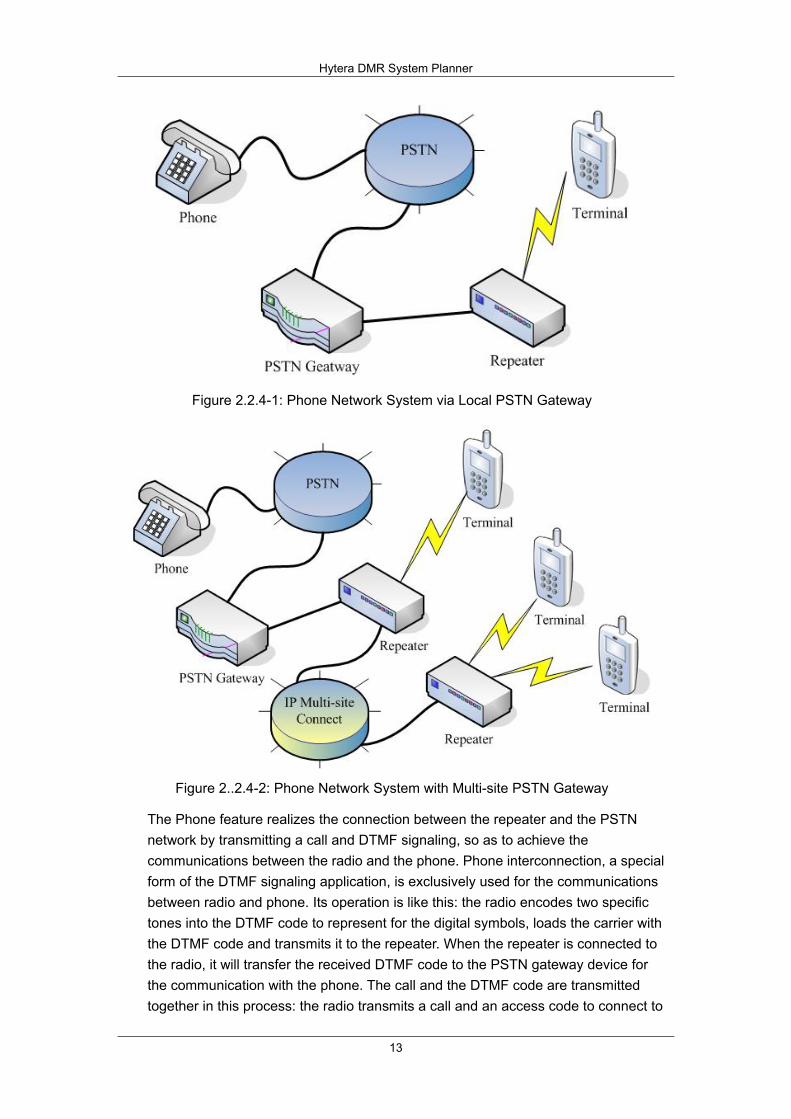
2.2.4 Phone
The Phone feature fullfils the communications between radio and phone via DTMF signaling and the PSTN system.
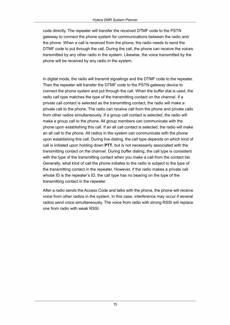
With the Phone feature, the radio can be connected to the local PSTN gateway device via the repeater, and then connected to the phone system, to realize the communications. Besides, the radio can be connected to the remote PSTN gateway device through the multi-site network to establish the communications. See the following two figures.
The Phone feature is supported in both analog mode and digital mode. If you use the multi-site network to realize the remote Phone feature, you should use the radio and the repeater both in digital mode. The Phone feature only supports a call between a radio of the system and a phone at a time, instead of multiple phones.
Hytera DMR System Planner
13
Figure 2.2.4-1: Phone Network System via Local PSTN Gateway
Figure 2..2.4-2: Phone Network System with Multi-site PSTN Gateway
The Phone feature realizes the connection between the repeater and the PSTN network by transmitting a call and DTMF signaling, so as to achieve the communications between the radio and the phone. Phone interconnection, a special form of the DTMF signaling application, is exclusively used for the communications between radio and phone. Its operation is like this: the radio encodes two specific tones into the DTMF code to represent for the digital symbols, loads the carrier with the DTMF code and transmits it to the repeater. When the repeater is connected to the radio, it will transfer the received DTMF code to the PSTN gateway device for the communication with the phone. The call and the DTMF code are transmitted together in this process: the radio transmits a call and an access code to connect to

Hytera DMR System Planner
14
the repeater and the public switched telephone network (PSTN) respectively, achiving its communications with a specific phone. The call ends when the radio sends the de-access code or when the phone is hung up. Like the call between the radios, the call between the radio and the phone is subject to time limit.
The DTMF (Dual-Tone Multi-Frequency) encoding technology uses two sepcific tones (high and low) to represent a number (as shown in the following figure), so as to realize some features. It is often designed with 16 keys (numeric keys 0~9 and function keys *, #, A, B, C and D). As the DTMF code consists of a high frequency (f1) and a low frequency (f2), the equation of corresponding signal is: F(t)=A.sin(2.pi.f1.t)+A.sin(2.pi.f2.t).
Figure 2.2.4-3: Tone Combination for DTMF
Note: A, B, C, D, and the pause code (“P”) only can be input via the CPS.
There are two dialing methods including live dial and buffer dial.
Live Dial: During the voice transmission via PTT, the radio will send the corresponding DTMF code immediately after you enter a digit via the keypad, like dialing the number on the phone. When you release PTT, the radio will stop the transmission. When making Live Dial operation, press the programmed key to transmit the access code.
Buffer Dial: Enter the needed DTMF code and then hold down PTT to transmit it, like dialing on the mobile phone. This method works only when you enable the DTMF keypad mode. You can enable the DTMF keypad via the CPS or the radio menu.
In analog mode, the radio will load the carrier with the DTMF code and transmit the
Low frequency
High frequency
Hytera DMR System Planner
15
code directly. The repeater will transfer the received DTMF code to the PSTN gateway to connect the phone system for communications between the radio and the phone. When a call is received from the phone, the radio needs to send the DTMF code to put through the call. During the call, the phone can receive the voices transmitted by any other radio in the system. Likewise, the voice transmitted by the phone will be received by any radio in the system.
In digital mode, the radio will transmit signalings and the DTMF code to the repeater. Then the repeater will transfer the DTMF code to the PSTN gateway device to connect the phone system and put through the call. When the buffer dial is used, the radio call type matches the type of the transmitting contact on the channel. If a private call contact is selected as the transmitting contact, the radio will make a private call to the phone. The radio can receive call from the phone and private calls from other radios simultaneously. If a group call contact is selected, the radio will make a group call to the phone. All group members can communicate with the phone upon establishing this call. If an all call contact is selected, the radio will make an all call to the phone. All radios in the system can communicate with the phone upon establishing this call. During live dialing, the call type depends on which kind of call is initiated upon holding down PTT, but is not necessarily associated with the transmitting contact on the channel. During buffer dialing, the call type is consistent with the type of the transmitting contact when you make a call from the contact list. Generally, what kind of call the phone initiates to the radio is subject to the type of the transmitting contact in the repeater. However, if the radio makes a private call whose ID is the repeater’s ID, the call type has no bearing on the type of the transmitting contact in the repeater.
After a radio sends the Access Code and talks with the phone, the phone will receive voice from other radios in the system. In this case, interference may occur if several radios send voice simultaneously. The voice from radio with strong RSSI will replace one from radio with weak RSSI.
Hytera DMR System Planner
16
2.3 Data Service
DMR data services include text message, GPS, supplement services, etc. In this chapter, we mainly introduce text message and GPS services.
2.3.1 Text Message
With DMR technology, you can send, receive, forward and save text messages using your radio. For your convenience, you can preset the regular text messages and save them in the radio in advance. Then you can send a preset message directly or after you edit it. In the radio with display, you can enter any text message via the keypad, save it in the radio and send it. As for the radio without display, you can only preset the message via the CPS, and send it by the programmed key. However, you are not able to check or edit it through the radio. You can use a Hytera DMR radio to send text message to an individual user, a group or the control station, and reply or forward the message to other radios.
Text messages are applied in:
Communication of sensitive information; Noisy environment where it is hard to hear the voice clearly; The radio with problem in voice services.
Text message include two categories: private message and group message.
Private message: text message sent between two radios. Group message: text message sent by a radio to a group of radios. The group
message differs from the private message in that it is a point-to-many service without acknowledge.
Parameter configuration
The same as private call, text message needs such parameter configurations: ID, color code, frequency and slot, and it is subject to Tx Admit.
As private message is sent between two radios, it does not involve a third party ID. Both parties must be in the same slot on the same channel and have the consistent Tx and Rx frequency and color code.
To send private message, you need to set the ID first. You may search for the receiver by the ID or the alias.
Hytera DMR System Planner
17
The Tx Admit settings of private message are the same as those of private call.
The same as group call, group message requires that all the members must be in the same slot on the same channel and have the consistent Tx and Rx frequency and color code.
The Tx Admit settings of group message are the same as those of private call.
2.3.2 GPS
DMR supports GPS technology. The GPS feature is mainly used to check the radio’s position and send GPS short message. You can send GPS message to inform the control station or other radios the geographic position you are at. The feature is only available for radios with the GPS modular.
GPS Setting
To apply the GPS feature, you need to enable it via the CPS. You can also set the time zone, GPS speed unit and its update time on actual requirements.
After the feature is enabled, the radio will automatically search for the satellite and update the GPS data until the feature is disabled.
GPS Message
GPS message is sent in DMR text message.
GPS Revert Channel
The GPS revert channel is used for GPS data report. After the radio makes successful RRS registration, the control station can require the radio to report its geographic position information according to the LP service agreement. And the radio will report its position information to the control station regularly. During the GPS data report, if the channel is occupied for other use, the radio will revert to the preset channel to send the GPS message.
You need to set the “GPS Revert Channel” parameter via the CPS prior to use this channel. When setting, you will need to consider the following notes:
This feature is available on the digital channel only. This parameter will be unavailable if "Rx Only" is checked for the channel. This parameter will be unavailable if "RRS" is unchecked for the channel. This parameter will be unavailable if "Forward to PC" in “Network” is checked.

Hytera DMR System Planner
18
2.4 General Services
2.4.1 Supplementary Service
Hytera DMR has the same supplementary service feature mechanism with Motorola. Hence, these two brands of radios can communicate with each other.
Hytera DMR radios have five supplementary services as follows:
Radio Check Remote Monitor Alert Call Radio Disable Revive
You can initiate any of these services via the radio menu or using the shortcut key assigned with One Touch Call feature. Meanwhile, the target radio must have the Decode feature to decode the command accordingly, otherwise, it will not be able to respond to the received command.
Radio Check
This feature is mainly used to check whether the target radio is in use in the system without disturbing it. When a Radio Check command is received, the target radio will give no visible or tone indication but will send back a confirmation message to the initiating radio automatically. This command is mainly used to see if the target radio is available. After the radio replies the confirmation message, the initiating radio can call the target radio or go on controlling it through other commands such as Remote Monitor, Radio Disable, etc.
To use the Radio Check feature, the Encode and Decode feature must be enabled for the initiating radio and the target radio respectively via the CPS.
Remote Monitor
With this feature, you can activate the microphone of the target radio remotely, so that the microphone will transmit the background voice to the initiating radio secretly. In this way, the initiating radio can monitor the target radio’s communications. You can set the time for remote monitor via the CPS.
The Remote Monitor feature is used to check the status of a radio which is already turned on but has no response. Such problem occurs in the following factors:

Hytera DMR System Planner
19
The target radio is stolen. You fail to use the radio properly. You need to have handsfree communications.
There are two types of remote monitor: remote monitor and emergency remote monitor. You need to configure the corresponding parameters for the target radio via the CPS. If only “Remote Monitor Decode” is selected, the target radio will decode the received Remote Monitor command and transmit a secret call in non-emergent situations. If you need the radio to decode the Remote Monitor command in emergency, you will need to select “Emergency Remote Monitor Decode” first. Only after you select this parameter, will the target radio decode the received Emergency Remote Monitor command and transmit a secret call to the initiating radio, otherwise, it will not respond.
Alert Call
With this feature, you can alert another user by sending the data such as signaling. When the target radio receives the data, it will alert that user by giving tone and LED indication, as well as the display (including the radio ID or alias) on the LCD, until the user clears these indications. When the target radio receives the Alert Call command, its user can press PTT to alert the initiating radio to make a call. If the target radio is a mobile radio, when it receives an alert call, it will alert the user by giving the horns, lights, etc.
To use the Alert Call feature, you need to preset the “Alert Call” parameter and the “Alert Call Decode” parameter for the initiating radio and the target one respectively via the CPS.
Radio Disable
Radio Disable allows you to remotely disable a lost or stolen radio, making it unavailable for operational use. The functions could help prevent potential risks. This function also allows you to temporarily disable a radio, to prevent unauthorized use of channel resource. The disabled radio will have a blank display and be unable to initiate or receive calls, but it can be turned on or off. If such phenomena happen to your radio, it means your radio is disabled. You can revive it through the CPS or another radio.
The target radio can only be disabled in the coverage of the system signals. When a radio is disabled during roaming or hunt, it will still be lockd on the channel at the station where it is disabled. To revive the radio, you must take it back there. Generally, all radios can be disabled by default. You can revise the configuration by setting the “Radio Disable” and “Radio Disable Decode” parameters via the CPS.
Hytera DMR System Planner
20
Radio Enable
This feature is used to revive a found radio which has been stolen or lost, as well as a radio which was disabled to release the channel.
The Radio Enable command works with the Radio Disable operation. Besides selecting the “Radio Disable/Enable Decode” parameter, you need to select the “Radio Enable” and “Radio Disable” parameters, or you can only enable the radio via the CPS.
2.4.2 One Touch Call
One Touch Call brings you a quick way to make a call.
Before using this feature, you need to associate the contact with the One Touch Call option, and set the programmable keys corresponding to the hard keys. After that, you can make a call or send a message to the preset contact by simply pressing the programmed key, instead of having successive operations via the radio menu.
You can set at most five One Touch Calls for your radio. When setting the parameters, you need to configure the “Call Mode” and the “Call List”, as well as the “Call Type” options. The “Call Mode” includes two categories: Digital and Analog. The modes must be associated with the programmable keys and the hard keys.
Call Mode:
None: To disable the One Touch Call function. Digital: To enable the One Touch Call function in digital mode. Analog: To enable the One Touch Call function in analog mode.
Call List: This option allows you to view all available contacts or shortcuts list.
In digital mode, available options include: None, Group/Private Call Alias. In analog mode, available options include: Smart Call1 – Smart Call5.
Call Typs: This option allows you to set the service type for One Touch Call.
Group contact: Available options include Group Call, Message and GPS Message.
Private Contact: Available options include Private Call, Message, GPS Message, Alert Call, Radio Check, Remote Monitor, Radio Enable and Radio Disable;
Quick Text: This option allows you to configure the text to be sent by One Touch Call.
Note: Only when the Cally Type is set to “Quick Text” can this feature be available. The message contents are from the Quick Text list in “DMR Services”.
Hytera DMR System Planner
21
When using the One Touch Call feature to transmit a private call or group call, you need to hold down PTT to complete the transmission. The One Touch Call feature is effective on the current channel only. Once you switch the channel when using it, the One Touch Call operation will terminate.
The configuration of One Touch Call does not cover the configuration of the services initiated through this feature. For example, if you need to have Radio Check operation through the One Touch Call feature, you also need to preset the Radio Check feature for both the initiating radio and the target radio, or the target radio will not respond to the Radio Check command. The One Touch Call feature is configured via the CPS other than the radio. Also, you cannot delete the preset One Touch Call contacts through the radio.
All the services (such as Private Call, Group Call, Radio Check, etc.) triggered by the One Touch Call feature will have the same process and effect as they are operated through the menu.
Note: When the radio is disabled or in emergency call, you cannot have One Touch Call operaion on it.
2.4.3 Encrypt
This function provides end-to-end encryption for communication (including voice and data) on digital channels, allowing the target radio rather than other unauthorized radios to receive the voice and data privately.
Hytera provides two types of encryption: basic encryption and advanced encryption. Only the communicating parties in the call know the encryption key. Advanced encryption provides two types of protocols: Hytera encryption and DMRA encryption. Hytera encryption adopts the encryption algorithm innovated by itself, and DMRA encryption is DMR standard encryption which applies the technology/encryption provided by DMR association. In addition, basic encryption adopts the encryption technology innovated by Hytera, too.
2.4.3.1 Basic Encryption
The basic encryption can prevent your voice or data from being eavesdropped or accessed by other party. It has the following features:
1) You can configure the key type and value freely. The key types: 40 bits (10 characters), 128 bits (32 characters) and 256 bits (64 characters).
2) It transforms the voice or data using simple mathematical algorithm.
The basic encryption applies simple algorithm based on the encryption key value to encrypt the voice or data. Though not so complicated as the advanced encryption

Hytera DMR System Planner
22
algorithm (e.g.: AES, ARC4), the basic encryption expands the encryption key value into three types with up to 256 bits. This provides more reliable protection to the transmitted voice and data, preventing the communications from eavesdropping.
Voice encrypted with this mechanism has the same system access time with unencrypted voice since no encryption parameter is required to be sent. See the following figure for the basic encryption flow.
Figure 2.4.3.1-1: Basic Encryption Process
* The key plays an important role in encryption. It is recommended to configure a unique key, which has at least five different bits from other keys after converted into binary value; otherwise a warning will pop up. However, this does not affect your operation.
2.4.3.2 Advanced Encryption
The advanced encryption provides a safer and more reliable encryption mechanism and encryption algorithm as introduced below:
1) You can configure the key type (40 bits, 128 bits and 256 bits) and value freely.
2) The advanced encryption with the key of 40 bits adopts ARC4 algorithm to generate the key stream for conversion of the original voice/data; as for the advanced encryption with with the key of 128 or 256 bits, it applies AES algorithm to generate the key stream for the conversion. Even with the same key, the advanced encryption will provide different key streams to the voice super frames and data packs, to avoid the attackers grasping the voice or data over the air for decoding the key.
During the encryption key generation through the algorithm, Hytera will have extra processing, while DMRA encryption will directly generate the key, as even with the same value, these two technologies will generate different keys.

Hytera DMR System Planner
23
In this mechanism, an extra header is required for sending the encrypted parameters, and it prolongs the system access time (by approximately 60ms). Meanwhile, the voice super frame will be embedded with some synchronous encryption information to prolong the system delay access time.
Hytera encryption defines its own way in embedding the encryption parameter into the voice super frame, which is different from the DMRA encryption.
See the following figure for the advanced encryption flow.
Figure 2.4.3.2-1: Advanced Encryption Process
With the different processes and the different ways of encryption, an encrypted radio by Hytera and that encrypted by DMRA encryption cannot communicate with each other.
2.4.3.3 MultiKey Decrypt
MultiKey Decrypt is used to decrypt the received voices and data from different radios with multiple keys defined in the list. Please be noted that the signal can only be decrypted with the corresponding key. Upon the receipt of the encrypted voice or data, the radio will find a key from the list to decrypt it. The MultiKey Decrypt is significant to system with strong confidentiality.
Hytera DMR System Planner
24
2.4.4 Telemetry
Telemetry is a function, which allows you to monitor devices remotely via the mobile radios. To be specific, when a mobile radio connects with the external device, you can monitor it remotely by another mobile radio. However, it is required to make some configurations related with telemetry for the mobile radio in advance.
In some work places, users may not always keep the devices nearby but need to monitor them any time. The Telemetry feature can help users to realize the remote monitor on the devices any time.
Currently, Hytera Telemetry feature is only available for conventional portable and mobile radios in digital mode, except repeaters.
The telemetry feature allows you to monitor and control the status of GPIO pins for a mobile radio attached to the external device, which in turn can monitor this device remotely by another mobile radio.
When a remote radio connects with an external device, it is capable of responding to the command sent by the current radio according to the predefined telemetry functionality. For example, you send a Query Status command to the target radio to obtain the GPIO status of the remote radio, so that the device user will know the operation status of the monitored device. The remote radio will output a level from the predefined GPIO Pin to control the external device.
To transmit the command, the radio must be configured with the Telemetry command. In addition, the programmable key shall be set to Telemetry Button, the GPIO port corresponding to the Telemetry VIO. In addition, all above configurations must be identical for both the target terminal and the originating terminal.
The same as other transmission by a radio in digital mode, the Telemetry command is subject to Tx Admit. When the channel or the color code is occupied, etc, the command cannot be transmitted. You can select the private call or group call from the contacts to send the telemetry command. However, the specific transmission mode varies with different telemetry commands.
Hytera DMR System Planner
25
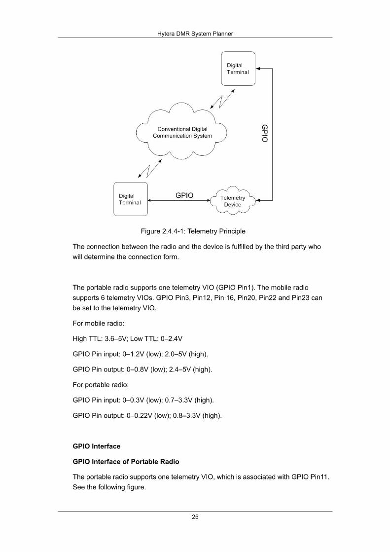
Figure 2.4.4-1: Telemetry Principle
The connection between the radio and the device is fulfilled by the third party who will determine the connection form.
The portable radio supports one telemetry VIO (GPIO Pin1). The mobile radio supports 6 telemetry VIOs. GPIO Pin3, Pin12, Pin 16, Pin20, Pin22 and Pin23 can be set to the telemetry VIO.
For mobile radio:
High TTL: 3.6–5V; Low TTL: 0–2.4V
GPIO Pin input: 0–1.2V (low); 2.0–5V (high).
GPIO Pin output: 0–0.8V (low); 2.4–5V (high).
For portable radio:
GPIO Pin input: 0–0.3V (low); 0.7–3.3V (high).
GPIO Pin output: 0–0.22V (low); 0.8–3.3V (high).
GPIO Interface
GPIO Interface of Portable Radio
The portable radio supports one telemetry VIO, which is associated with GPIO Pin11. See the following figure.

Hytera DMR System Planner
26
Figure 2.4.4-2: GPIO Interface of Portable Radio
GPIO Interface of Mobile Radio
The mobile radio supports 6 telemetry VIOs. GPIO Pin3, Pin12, Pin 16, Pin20, Pin22 and Pin23 can be set to the telemetry VIO. See the following figure:
Figure 2.4.4-3: GPIO Interface of Mobile Radio

Hytera DMR System Planner
27
Voltage Range of GPIO Pin
For mobile radio:
High TTL: 3.6–5V; Low TTL: 0–2.4V
GPIO Pin input: 0–1.2V (low); 2.0–5V (high).
GPIO Pin output: 0–0.8V (low); 2.4–5V (high).
For portable radio:
GPIO Pin input: 0–0.3V (low); 0.7–3.3V (high).
GPIO Pin output: 0–0.22V (low); 0.8–3.3V (high).
There are three ways to activate the Telemetry feature: pressing the programmed Telemetry key, GPIO status change and receiving the appropriate command from other radios.
To activate this feature by a programmable key, you need to perform related operations with the radio and assign it to the programmable key. For example, you can associate the “Send Pulse Command” with “Telemetry Button”, and assign “Send Pulse Command” to TK key. Then you can press the TK key to send pulse command.
When the radio is connected with a telemetry device, any change in device status would result in GPIO status change. Providing there is any command associated with GPIO status change, the radio will implement the command when GPIO status changes. For example, when the GPIO status changes as a result of the change in the status of connected telemetry equipment, the radio will implement the predefined command, namely, it will send its GPIO status to the target radio. In this way, you can know the status of other equipment remotely.
When a radio receives the command from another radio, it will perform an appropriate operation associated with the command. For example, it receives “Toggle Voltage Command”, and it will toggle the voltage of specified GPIO Pin as configured previously.

Hytera DMR System Planner
28
2.4.5 VOX
The VOX (Voice-operated Transmit) feature indicates that you can trigger the voice transmission by voice directly rather than PTT. This brings more convenience to you in radio use.
After this feature is enabled, when the microphone detects that your voice reaches the required volume to trigger the transmission, your voice will be transmitted automatically.
To use the VOX feature, you need to predefine the parameters, especially the “VOX Gain Level”. Generally, a radio has an internal microphone and an external one. The internal microphone is a built-in microphone in the radio; the external microphone is on the accessory. Different microphones have different gain levels. In the CPS, there are parameters for the external and internal microphone respectively. For both microphones, the bigger the gain value is, the higher the gain level and the lower the sensitivity will be. Adjust the “VOX Gain Level” properly on your actual requirements.
In actual use, VOX will not work until the detected voice reaches the required volume. As we know that people talk with some pauses. During the pauses, the microphone detects no voice fulfilling the requirements. If it stops the transmission then, the user’s communication fluency will be affected. To avoid this, the system provides the VOX Hold Time: during the voice transmission, the radio will hold the transmitting status even if the detected voice is under the required volume, so the communication will be smooth. The VOX Hold Time shall be defined regarding the your speaking habits. If it is set too long, the radio will stay in transmitting status even if you have finished talking, which will consume more power of the radio; too short time will affect the communication.
You should have reasonable configurations of the other parameters of VOX to fit different environments. Besides, the radio or microphone should be put in proper position, so as to avoid the transmission when the environmental noise meets the volume requirements.
Hytera DMR System Planner
29
Note that the voice transmission via VOX is the same as holding down PTT in that the radio will also give a tone for available communication. During transmission, if no voice is detected, the radio will start VOX Hold Time counting. If the time is over without any voice detected, the transmission will terminate and the radio will enter the Call Hang Time.
When the radio is in use, its speaker will play such sound as tones and the received voice. These sounds may also be detected when VOX is active. To prevent transmitting such sounds, the radio will automatically disable the microphone detection when the speaker is on and enable it again when the speaker is off.
When in auto transmission such as the hot microphone on for an emergency alarm or remote monitor, the radio will disable VOX.
VOX is a feature associated with the current channel and will not affect other channels. The VOX feature can be enabled/disabled through the following three methods:
Radio menu; Programmable key; CPS.
When using PTT, the VOX will be paused, but the feature on the current channel is still active, no matter whether the radio is switched to other channel or rebooted.
Hytera DMR System Planner
30
2.5 Emergency Alarm
This feature helps you to request for aid in emergency. When an Emergency system is associated to a channel, you can activate emergency feature through the programmed key.
Hytera DMR system provides four types of emergency alarms:
Siren Only: The radio emits siren locally.
Regular: The radio gives visible and audible indications during emergency state.
Silent: The radio gives no indication during emergency state.
Silent with Voice: The radio gives no indication during emergency state, but will unmute its speaker once it receives a call.
You can select the alarm type on actual requirements. Siren Only indicates the radio will not transmit the emergency code and emergency call, but only emit siren for warning. This type is mainly applied in public activities in which you need no other support. When some support is needed, you can choose Regular, so the radio will transmit the emergency code or emergency call. Some visible and hearable indiations will be given. In special occasions, it may be inconvenient to you to make emergency operation with visible and hearable indications. Silent type will be preferable then, as during the transmission of silent alarm, the radio will not give any visible or hearable indications, not affecting the operation of the receiving radios in the system. A radio with automatic emergency call will receive acknowledge from other emergency alarm receiving radios. If Silent is selected, the emergency calling radio will mute the speaker despite of received voices, and you will not know other users’ responses. If you want to hear the acknowledge from other radios when using Silent alarm, you can choose Silent with Voice for your radio. In this alarm type, the radio will only play the received responding voices from other radios without giving any other visible or hearable indications.
In DMR emergency system are three emergency modes:
Alarm: The radio only triggers emergency process after you activate Emergency.
Alarm with Call: The radio sends emergency alarm and the emergency call upon Emergency activation.
Call Only: The radio only transmit emergency call upon Emergency activation.
Hytera DMR System Planner
31
Alarm mode is used to inform the other radios in the system that you need help. Those radios will check the ID of the transmitting radio and take actions. This emergency mode can inform the other users that you are in danger, but it cannot tell your actual situation. Hence, the other users cannot take correct measures for help. In this case, you can use Call Only to transmit an emergency call so that the other users in the system will know your actual needs. The Alarm with Call mode indicates you can send the emergency alarm and the emergency call together. It is useful when the current channel is occupied, which blocks the emergency alarm. The system has a revert channel for the radio to transmit the emergency alarm. You can define the revert channel on actual requirements. And note that the preset channel shall be convenient to other users for receiving and seldom occupied. In the revert channel, the transmitting contact must be a group call contact rather than a private call contact. To avoid mistaken configuration, the channel on which the transmitting contact is a private call contact is unavailable when you are setting the revert channel for emergency alarm.
2.5.1 Alarm
In this mode, after the emergency alarm is enabled, the radio will transmit the emergency code; when other users in the system receive the code, they will give an ACK (acknowledge), and then the emergency code transmitting radio will enter the emergency status. You can set the code to be sent for multiple times, to arouse the attention of the other users or to avoid transmission failure due to abnormal channel. You can define the times of emergency code transmission by setting the “Impolite Retries” and “Polite Retries” in the CPS. An impolite transmission occurs despit of the occupied channel, while a polite transmission will not take place forcibly. The polite transmission indicates that radio will wait and suspend transmitting if the channel is busy, but will transmit forcibly after a certain period if the channel is always busy. The transmission times will only be configurable during the emergency alarm or emergency call transmission.
During the emergency alarm, the radio will transmit the emergency code on the emergency transmitting channel, and will wait for one ACK from the receiving radios. The radio will retry the transmission and wait for the ACK. When waiting for the ACK, the radio will only take the ACK code as effective. If no ACK is received within the transmission retries, the radio will give an indication and quit the emergency status. When the radio is waiting for the ACK, if PTT is held down, the ACK is received or the retries (including all the impolite and polite retries) are all used, the radio will quit the emergency status.

Hytera DMR System Planner
32
2.5.2 Emergency Call
This mode indicates that the radio will transmit the emergency call on the emergency channel, and then directly enter the emergency status instead of transmitting the emergency code and waiting for the ACK. You can transmit the emergency call by holding down PTT. Sometimes, you cannot hold down PTT. In that case, other users in the system will not receive your call so they will not know your situation. To avoid this, you can define the automatic emergency call which is transmitted via the microphone without using PTT. You can set the voice cycles, handsfree transmission starting time and duration.
After entering the emergency alarm, the radio will stay on the emergency transmitting channel. Now you can make an alarm with emergency call using PTT and receive alarms with emergency calls.
In automatic emergency call, the radio will transmit emergency call automatically and receive emergency calls. It will also make voice cycles as predefined, and enter the emergency status after transmission. If you hold down PTT to respond when receiving an emergency call, the voice cycle will terminate and the radio will enter the emergency status.
2.5.3 Alarm with Call
Alarm with call combines the emergency call with the alarm. After the emergency system is started, the radio will need to wait for an ACK. When the ACK is received, the radio will enter the emergency status and you can hold down PTT to transmit an emergency call. You can also make the call using PTT during waiting for the ACK, but the radio will directly enter the emergency status and stop sending the emergency code.
After the alarm with call is activated, the radio will send the emergency code and wait for the ACK circularly. After the cycles, it will enter the emergency status in which you can hold down PTT to make en emergency call.
The radio can also transmit an emergency call automatically after it sends the emergency code and waits for the ACK. The automatic emergency call needs configuration via the CPS.
Hytera DMR System Planner
33
2.5.4 Lone Worker
Lone Worker emergency is used to ensure your safety. You can set a time period for your radio. If no keypad operation is made on the radio within this period, the radio will trigger the emergency alarm automatically. This feature is designed for people (such as police, firefighters, miners, etc.) in dangerous workplaces.
With this feature, the radio will automatically transmit an alarm to alert the related users when you are in danger and fail to take any actions.
Lone Worker is a timed emergency feature. Within the preset Lone Worker Response Time, if there is not any operation on the radio keypad, the radio will transmit an emergency alarm to inform the related users that you are in danger. If you operate the radio within the preset time, the radio will not transmit the alarm, and the Lone Worker Response Time will be counted from the beginning again. There may be mistaken alarm in actual use, so another feature is added: Lone Worker Remind Time. In the preset period, the left Lone Worker Response Time, before the Emergency mode is initiated, the radio will remind you that the alarm is due. If you are safe, you can have any key operation to relieve the radio from alarm.
You can define the Lone Worker feature, as well as the Lone Worker Response Time and Lone Worker Remind Time under the feature, via the CPS only. If you want to activate or inactivate the feature through the radio, you must select “Lone Worker” option in “Menu” in the CPS. You can assign the programmable key with Lone Worker feature, so you can activate or inactivate the feature by pressing the key. Besides, you can also set the Lone Worker feature to be activated automatically via the CPS. You can use any of the aforesaid three ways to activate this feature.

Hytera DMR System Planner
34
Lone Worker Process:
Figure 2.5.4-1: Lone Worker Process
2.5.5 Man Down
Man Down emergency is also used to protect you. When the radio tilts for over the predefined time, it will trigger the emergency alarm automatically. This feature is designed for users (such as police, firefighters, miners, etc.) in dangerous workplaces.
The principle of this feature is that the gravity sensor built in the radio will sense the tilting gradients. When the gradient is sensed over the preset value, the emergency alarm feature will be activated. When the radio stays over the preset gradient for the preset delay time, it will transmit the emergency alarm. If the radio is placed upright during the alarm, it will quit from the alarm after another preset delay time. Like Lone Worker, Man Down has Pre-Alert Time before the emergency alarm. Within this period, if you place the radio upright, the radio will not transmit the emergency alarm.
Compared with Lone Worker feature, Man Down feature is more sensitive and timely, and it spends shorter time before triggering the alarm, while Lone Worker will wait at least 1min before triggering the alarm. The Man Down feature is more suitable to users in dangerous workplaces. However, more mistaken alarms may be sent by radio with this feature than Lone Worker. Thus, it is more important to set the reasonable emergency entry delay time and tilting gradient for the Man Down feature.

Hytera DMR System Planner
35
As the Man Down feature is more sensitive and timely to send emergency alarms, it should be used in appropriate occasions and defined reasonably. To use this feature, you need to configure its parameters via the CPS. The Trig Entry Delay Time is used to set the time period for activating the emergency alarm. You should set it based on actual requirements. In very dangerous place, you need to set the time shorter so the radio will be more sensitive for alarm triggering. You can also set the Trig Exit Delay Time to define the time period before which the emergency mode is quited.
Like the Lone Worker feature, Man Down is also an expanded emergency feature. You can configure this feature via the CPS only. If you want to activate or inactivate the feature through the radio, you must select “Man Down” option in “Menu” in the CPS. You can assign the programmable key with Man Down feature, so you can activate or inactivate the feature by pressing the key. Besides, you can also set the feature to be activated automatically via the CPS. You can use any of the aforesaid three ways to activate this feature.
Man down Process:
Figure 2.5.5-1: Man Down Process
Hytera DMR System Planner
36
2.6 Scan
With the Scan feature, the radio can detect the communication activities on other channels and select the channel for staying on according to the scan result. After you start the scan of the radio via the programmable key or radio menu, the radio will scan the activities on the preset channels circularly in order. When detecting some activities that you are interested in on a channel, the radio will pause on that channel until the Hang Time is up. Then the radio will continue detecting the channels repeatedly until it quits the Scan mode. Hytera DMR scan supports both digital channels and analog channels.
The Scan feature shall be activated in the following conditions:
The “Scan List” parameter in “Channel” cannot be set to “None”; There are at least two channels in the Scan List, or you cannot activate the
feature.
When the conditions above are all fulfilled, you can also select the Auto Scan feature for a channel, so when you switch the radio to the preset channel, the Auto Scan will be activated. When scanning, the radio will stay on an active channel for some time before it scans another channel, so as not to miss the activity detection. You can set the time for staying (Hang Time) via the CPS.
There are some scan statuses:
Scan: The radio detects the activities on the channels, listed in the Scan List, in order.
Stay: If there are some communication activities that satisfy the requirements on staying on a channel, the radio will stay on that channel until the Hang Time is over. Then it will continue to scan other channels.
Sweep: When the radio stays on a low-priority channel, the priority channel Sweep Time will alert the radio to detect the high-priority channel. When there is active signal detected on the priority channel, the radio will jump to it immediately; in case of no signal detected, the radio will stay on the current channel.
Suspend: During scanning the analog channels, you can enter or quit this status by pressing the programmed Monitor key or Squelch Off key. In this status, the radio can sweep the priority channels.
Terminate: When the radio receives the special code such as the emergency code, it will terminate the scan. It will stay in this status and not scan or sweep.
Off Hook: This status occurs only in mobile radio scan. The scan process is affected if the microphone is off the hook.
Hytera DMR System Planner
37
The radio may need to transmit during the scan, while the stayed channel, selected channel, last active channel and frequently used channel are different channels. Thus, you need to designate a transmitting channel for the radio. During the transmission when scanning, you may need to call on the current channel, or respond to the detected voice on the stayed channel, or call a user on the frequently used channel. To meet your needs, Hytera DMR provides the Scan Tx Mode configuration in the CPS, so you can designate a channel for the transmission during the scan. You can have the following configurations:
Selected Channel: to transmit on the current channel. Last Active Channel: the channel the radio stayed on last time. Designed Channel: to transmit on the specified channel.
If the Talkback feature is enabled, when the radio is staying on a channel, it will transmit on that channel rather than the preset channel in Scan Tx Mode. If the radio is scanning, it will transmit on the preset channel in Scan Tx Mode. If sweeping the priority channel, it will go back to the stayed channel before the sweeping to transmit.
If some mismatching signals are detected during scan, the system will mark the channel. And the radio will only detects whether a carrier is present on the marked channel during next scan process. If a carrier is present on the marked channel, the counter increases a step, and the radio will go to the next channel for detecting. Otherwise, the counter resets and the radio will check all conditions next time. If the counter counts up to ten (10), the radio will clear this mark and check all conditions next time. This feature is defined via the CPS. Even if the feature is not set, the radio will still check all conditions of the channel and stay on it for some time. This feature is used to save the scan time. The scan may take a long time. To those channels with mismatching signals, the system will still scan and stay for some time. In deed, the time can be saved in the way that the system marks such channels and simply scan them next time and skip to other channels.
Hytera DMR scan provides Priority Channel Sweep function. During the scan, missed detection of some channel activities is inevitable. To avoid missing detecting the activities on some high-priority channels, the system can be timed to return to the priority channel for scan.
When the radio detects the active channel, it will stay in the channel. And it will sweep a higher-priority channel. When there is active signal detected on the priority channel, the radio will jump to it immediately; in case of no signal detected, the radio will stay on the current channel. To use the Priority Channel Sweep function, you simply need to set the sweep time according to the urgency. The sweep time range
Hytera DMR System Planner
38
is: 0.5s to 7.5s. The shorter the set time, the faster the radio will return to the first channel for scanning, and the more the scanning of the priority channel. Thus the detection to the first channel activities will not be missed.
Off Hook Scan is only available for mobile radios. With this feature enabled, when you pick up the microphone, the scan will be paused; if the feature is disabled, the scan will not be affected when you pick up the microphone.
2.6.1 Scan List
The radio will scan channels in accordance with the Scan List. When scanning channels, the radio will detect the activities on the channels. When a valid activity is detected on a channel, the scan will pause and the radio will stay on the channel until the end of the Hang Time, and then the radio will continue to scan.
The Scan List can contain the analog channel and digital channel; a channel can be increased to both a single scan list and multiple scan lists. You can add or delete the channel(s) in the scan list via the CPS or the radio menu, and you can edit the channel(s) via the CPS. Similarly, a radio can have a scan list and contain a plurality of scan lists. The system has a scan list by default. If you need to enable the scan function, you must set a scan list for the radio via the CPS.
Scan is a channel associating feature. You must set a scan list prior to enabling this feature. You can set the Auto Start Scan feature for a channel via the CPS or start scan manually after you define the scan list.
During the scan, some frequently used channels or important channels need frequent scan. You will need to pay more attention to these channels and give them prior scan. Via the CPS, you can define at most two priority channels. The priority channels have totally 50% more chances to be scanned, so each of the two predefined channels share 25% of the chances.
Hytera DMR System Planner
39
2.6.2 Scan Stay Condition
The radio detects the signal and determines whether to stay on the channel during scanning.
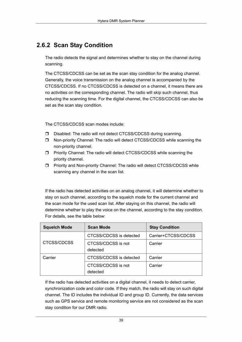
The CTCSS/CDCSS can be set as the scan stay condition for the analog channel. Generally, the voice transmission on the analog channel is accompanied by the CTCSS/CDCSS. If no CTCSS/CDCSS is detected on a channel, it means there are no activities on the corresponding channel. The radio will skip such channel, thus reducing the scanning time. For the digital channel, the CTCSS/CDCSS can also be set as the scan stay condition.
The CTCSS/CDCSS scan modes include:
Disabled: The radio will not detect CTCSS/CDCSS during scanning. Non-priority Channel: The radio will detect CTCSS/CDCSS while scanning the
non-priority channel. Priority Channel: The radio will detect CTCSS/CDCSS while scanning the
priority channel. Priority and Non-priority Channel: The radio will detect CTCSS/CDCSS while
scanning any channel in the scan list.
If the radio has detected activities on an analog channel, it will determine whether to stay on such channel, according to the squelch mode for the current channel and the scan mode for the used scan list. After staying on this channel, the radio will determine whether to play the voice on the channel, according to the stay condition. For details, see the table below:
Squelch Mode Scan Mode Stay Condition
CTCSS/CDCSS is detected Carrier+CTCSS/CDCSS CTCSS/CDCSS CTCSS/CDCSS is not
detected Carrier
CTCSS/CDCSS is detected Carrier Carrier
CTCSS/CDCSS is not detected
Carrier
If the radio has detected activities on a digital channel, it needs to detect carrier, synchronization code and color code. If they match, the radio will stay on such digital channel. The ID includes the individual ID and group ID. Currently, the data services such as GPS service and remote monitoring service are not considered as the scan stay condition for our DMR radio.
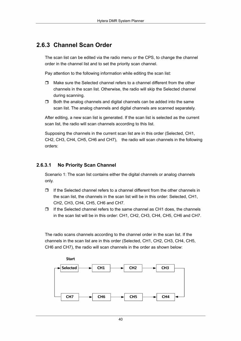
Hytera DMR System Planner
40
2.6.3 Channel Scan Order
The scan list can be edited via the radio menu or the CPS, to change the channel order in the channel list and to set the priority scan channel.
Pay attention to the following information while editing the scan list:
Make sure the Selected channel refers to a channel different from the other channels in the scan list. Otherwise, the radio will skip the Selected channel during scanning.
Both the analog channels and digital channels can be added into the same scan list. The analog channels and digital channels are scanned separately.
After editing, a new scan list is generated. If the scan list is selected as the current scan list, the radio will scan channels according to this list.
Supposing the channels in the current scan list are in this order (Selected, CH1, CH2, CH3, CH4, CH5, CH6 and CH7), the radio will scan channels in the following orders:
2.6.3.1 No Priority Scan Channel
Scenario 1: The scan list contains either the digital channels or analog channels only.
If the Selected channel refers to a channel different from the other channels in the scan list, the channels in the scan list will be in this order: Selected, CH1, CH2, CH3, CH4, CH5, CH6 and CH7.
If the Selected channel refers to the same channel as CH1 does, the channels in the scan list will be in this order: CH1, CH2, CH3, CH4, CH5, CH6 and CH7.
The radio scans channels according to the channel order in the scan list. If the channels in the scan list are in this order (Selected, CH1, CH2, CH3, CH4, CH5, CH6 and CH7), the radio will scan channels in the order as shown below:

Hytera DMR System Planner
41
Scenario 2: The scan list contains both the digital channels and analog channels.
For example, CH1, CH3, CH5 and CH7 are digital channels, and CH2, CH4 and CH6 are analog channels.
If the Selected channel is an analog channel and refers to a channel different from the other channels in the scan list, the channels in the scan list will be in this order: Selected, CH2, CH4, CH6, CH1, CH3, CH5 and CH7.
If the Selected channel is a digital channel and refers to a channel different from the other channels in the scan list, the channels in the scan list will be in this order: CH2, CH4, CH6, Selected, CH1, CH3, CH5 and CH7.
If the Selected channel is a digital channel and refers to the same channel as CH1 does, the channels in the scan list will be in this order:: CH2, CH4, CH6, CH1, CH3, CH5 and CH7.
If the Selected channel is an analog channel and refers to the same channel as CH2 does, the channels in the scan list will be in this order: CH2, CH4, CH6, CH1, CH3, CH5 and CH7.
The radio scans channels according to the channel order in the scan list. If the channels in the scan list are in this order (Selected, CH2, CH4, CH6, CH1, CH3, CH5 and CH7), the radio will scan channels in the order as shown below:
2.6.3.2 One Priority Scan Channel
Supposing only CH1 is set as the priority scan channel, the channels in the scan list will be in this order (Selected, CH1, CH2, CH3, CH4, CH5, CH6 and CH7), no matter whether they are analog channels or digital channels.
Then the radio will scan channels in the following order:
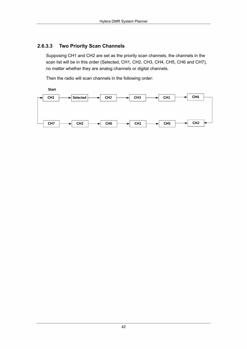
Hytera DMR System Planner
42
2.6.3.3 Two Priority Scan Channels
Supposing CH1 and CH2 are set as the priority scan channels, the channels in the scan list will be in this order (Selected, CH1, CH2, CH3, CH4, CH5, CH6 and CH7), no matter whether they are analog channels or digital channels.
Then the radio will scan channels in the following order:
Hytera DMR System Planner
43
2.7 Roaming
Roaming is a function, which allows mobile terminals to move between sites in the IP Multi-site Connect system without dropping connection. It is fully automatic to users.
The Roaming feature, mainly used in the IP Multi-site Connect system, can bring users seamless communication within the area covered by multiple repeaters.
Hytera DMR digital terminals are capable of auto roaming from one site to another within the IP Multi-site Connect system.
A roam list can be configured to the mobile terminal. It contains a series of channels, each of which is corresponding to a repeater in the IP Multi-site Connect system (namely, a wide area channel). When the Roaming feature is enabled, the mobile terminal will keep detecting the signal strength of each channel in the roam list, select one with the strongest signal and regard it as the master site. Then the mobile terminal will stay on this site. Once its signal strength falls below the pre-programmed RSSI threshold value, the mobile terminal will try to find a new master site. If a better site is not found, it will still identify the previous master site as its own master site.
Note: The terminal cannot roam when it is in a call.
If there is no activity in the IP Multi-site Connect system, e.g. no voice or data service transmitting, the beacon configured for the repeater will be sent automatically. Once the terminal finds which master site is idle, it will wait for this beacon and detect its signal strength, measuring the coverage of the site and determining the relation between the terminal and the site. If no voice, data service, or the beacon has been received in the expected duration, the mobile terminal will be deemed to exceed the coverage of the master site and attempt to search for a new master site.
As the Roaming function can be enabled or disabled via the programmable keys or the menu, the users can not only control when and where the mobile terminal roams, but also disable this feature to a specific site, or keep roaming to choose a proper site.
During roaming, voice or data service is initiated, which fails to activate the repeater at the master site at times. In this case, the terminal will search sites in the roam list and select an appropriate one to make a call. If the right site is not found, the out-of-range message will be given. To manually change the site, users can rotate the Channel Selector knob to the desired channel. Then the mobile terminal always begins to roam from this channel.

Hytera DMR System Planner
44
When the mobile terminal is roaming, the corresponding status icon and the master site (channel) alias will be displayed on the LCD. Also you can determine whether the terminal is searching or staying on the site with the help of the LED.
2.7.1 Roaming Methods
The type of roaming method includes auto site roam and active site roam.
2.7.1.1 Auto Site Roam
If the Roaming feature is enabled and the signal strength value of the current channel falls below the pre-programmed RSSI threshold, the mobile terminal will keep detecting the signal strength of each channel (site) in the roam list, select one with the strongest signal, and regard it as the master site. Afterwards, the mobile terminal will stay on this site. Once the signal strength of the master site falls below the RSSI threshold, the mobile terminal will try to find a new master site. If a better site is not found, it will still identify the previous channel as its own master site. If the mobile terminal comes across other activities while performing the auto site roam, it will identify the current repeater as the master site. In addition, all sites in the roam list will be ranked according to their signal strength, so as to achieve better roaming performance. Sites that have been detected in previous roam and are assumed to be near by are searched before those that have not been detected before. Additionally, when the mobile terminal is roaming, it will detect the current master site during the interval of checking other two sites, to minimize the duration away from the master site. This strategy gives the priority to the previous master site and minimizes the possibility of missing transmissions in the process of roaming.
When the auto site roam is initiated, the mobile terminal will be temporarily away from the master site and detect other sites. In this case, it may miss the communication with the master site. In other words, auto site roam shall occur when the mobile terminal is so far from the master site that its signal strength had deteriorated below the RSSI threshold or when there is no signal at all.
Both the activation of auto site roam and site selection are subject to the repeater transmission. If there is no activity in the system and the repeater stops transmission, auto site roam can not detect any repeater. Consequently, the repeater can be configured to send the beacon periodically in case of no transmission and interference. Both the beacon duration and interval can be set.
In the event of no activity in the system, the mobile terminal will use the signal strength of the beacon to determine whether it is required to roam and which site it should roam to. If the mobile terminal does not receive the beacon within the interval, it is deemed to be out of the repeater’s range and roams to another site.

Hytera DMR System Planner
45
Auto site roam is not triggered by one of the following events:
The mobile terminal is transmitting The mobile terminal is receiving a call or data service The mobile terminal is in Emergency mode The mobile terminal is in good coverage The mobile terminal is operating in Talk Around mode The mobile terminal is killed The mobile terminal is monitoring remotely The menu of the mobile terminal is active The mobile terminal operates on the channel with a scan list
2.7.1.2 Active Site Roam
With the active site roam enabled, if the user presses the PTT or the emergency key, or the message is sent, the mobile terminal will first try to wake up the repeater on the current channel. If a repeater is not available, the mobile terminal will repeat this process for each member in the roam list till an active one (site) is found. Afterwards, the mobile terminal will synchronize itself with this active repeater, finish the transmission and identify it as the master site. If the entire roam list is searched and no site is found, a failure indication will be provided to the user.
The active site roam will occur when the mobile terminal initiates a call but the corresponding repeater on the current channel is not waked up.
This entire process of discovering and synchronizing with an active repeater increases the voice access time of the transmission (time from PTT press to Talk Permit Tone). But this increase only takes place in the first transmission, as the later transmission will perform normally on the new site.
Note: the wake-up message is always sent politely. This indicates that if the mobile terminal detects the inference signal, it will not send this message to members in the roam list. But it will carry on the active site roam according to the next roam list.
Note: the mobile terminal does not perform any auto site roam in emergency mode. No auto roaming will occur when the mobile terminal is reverted during the emergency. However, when configured to revert emergency channel and with the active site roam enabled, the mobile terminal will perform the active site roam automatically, if the signal strength of the repeater falls below the pre-programmed RSSI threshold, or no repeater beacon is detected.
Please note that the wake-up message caused by the active site roam will be transmitted to each member’s frequencies in the roam list till the available site is found. But the active site roam will not occur in the area where frequency overlapping and sharing is common. In order to minimize the unnecessary transmission, the mobile terminal only sends one piece of wake-up message politely. If this is not acceptable, the active site roam shall be disabled and the beacon be set

Hytera DMR System Planner
46
as short as possible. This ensures that the auto site roam finds a new site rapidly and disallows the user to initiate the active site roam.
Note: roaming will not occur in the emergency mode if the active site roam is disabled.
2.7.1.3 Configuring the Roam List
It must be noted that a system contains more than one IP Multi-site Connect system, namely, a wide area system. In general, a wide area system comprises one or multiple wide area channels, each of which is a separated voice path. Hence, the user only needs to configure the required wide area channel to the roam list.
You can refer to IP Multi-site Connect Application Notes for details about the wide area system.
It is necessary to store the required site into the roam list. This list shall contain a logic channel, which includes the frequency pair, color code and time slot combination.
It is important to understand that when the mobile terminal determines a new master site to be a member in the roam list, only the logical attributes in this list are utilized and other attributes are used from the selected channel personality.
The following logic attributes of the master site shall be utilized:
Transmit frequency and transmit reference frequency Receive frequency and receive reference frequency Color code Time slot Talk Around setting GPS Revert channel Emergency (include Emergency Revert Channel)
More attention shall be paid to GPS revert and emergency revert. Because the logical channels for each site are different, the revert channels must be changed when the mobile terminal roams from one site to another. We recommend that emergency configurations for all channels should remain the same within a roam list. Otherwise, the mobile terminal may perform an emergency differently when it moves from one site to another.
The remaining attributes, such as Transmit and Receive Group List, Channel Access, etc, should be utilized from the currently selected channel, no matter which site the mobile terminal currently roams to. Preferably, the attributes of these parameters in the roam list shall keep the same, so that the mobile terminal operates consistently no matter whether it roams to the channel or the user selects the channel.

Hytera DMR System Planner
47
2.7.2 Configuring the RSSI Threshold
The RSSI Threshold is a configurable parameter via the CPS. If the signal strength of the current master site is above the specified RSSI threshold, the terminal will stay on the site and will not roam. Once the signal strength falls below the threshold, the auto site roaming will occur to search for a site with higher signal strength. This parameter actually controls the distance away from a site a user will begin searching for another site. The RF coverage is not a perfect circle in reality, but to simplify this explanation, we regard it as a circle.
Please note that the terminal will temporarily leave the current master site to determine whether a stronger site is available during auto site roaming. Since the terminal is temporarily away from the master site, it may miss the beginning of a transmission (i.e. late entry into a call). Therefore, it is not advisable to perform auto site roaming all the time. The RSSI threshold should be set properly. If it is too low, the terminal will always stay on the master site with low signal strength even if there might be a better site available; if it is too high, the terminal will frequently roam and cause late entry. The figure below illustrates the situations when the RSSI threshold is set too high or too low. Strong signals exist in the area circled by the dotted line, and terminals can roam in the light blue area. The RSSI Threshold value ranges from -120dBm to -80dBm.
Figure 2.7.2-1:Roaming Triggered by RSSI Threshold
The default value is -108dBm, which indicates approximately 80% of the good coverage. Therefore, roam will occur in the left 20% of the coverage. The default value is ideal for most configurations, but may not be the best in some particular configurations. Accordingly, the user must take the actual site configuration into
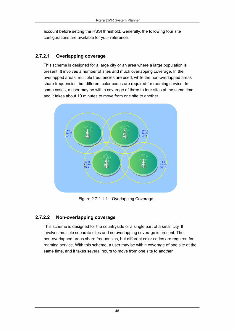
Hytera DMR System Planner
48
account before setting the RSSI threshold. Generally, the following four site configurations are available for your reference.
2.7.2.1 Overlapping coverage
This scheme is designed for a large city or an area where a large population is present. It involves a number of sites and much overlapping coverage. In the overlapped areas, multiple frequencies are used, while the non-overlapped areas share frequencies, but different color codes are required for roaming service. In some cases, a user may be within coverage of three to four sites at the same time, and it takes about 10 minutes to move from one site to another.
TX=F1RX=F2CC=4
TX=F5RX=F6CC=2
TX=F1RX=F2CC=1
TX=F3RX=F4CC=3
TX=F1RX=F2CC=4
TX=F5RX=F6CC=2
TX=F1RX=F2CC=1
TX=F3RX=F4CC=3
Figure 2.7.2.1-1:Overlapping Coverage
2.7.2.2 Non-overlapping coverage
This scheme is designed for the countryside or a single part of a small city. It involves multiple separate sites and no overlapping coverage is present. The non-overlapped areas share frequencies, but different color codes are required for roaming service. With this scheme, a user may be within coverage of one site at the same time, and it takes several hours to move from one site to another.
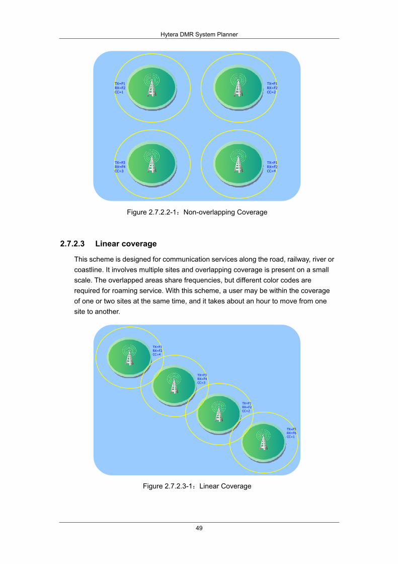
Hytera DMR System Planner
49
TX=F3RX=F4CC=3
TX=F1RX=F2CC=4
TX=F1RX=F2CC=1
TX=F1RX=F2CC=2
Figure 2.7.2.2-1:Non-overlapping Coverage
2.7.2.3 Linear coverage
This scheme is designed for communication services along the road, railway, river or coastline. It involves multiple sites and overlapping coverage is present on a small scale. The overlapped areas share frequencies, but different color codes are required for roaming service. With this scheme, a user may be within the coverage of one or two sites at the same time, and it takes about an hour to move from one site to another.
TX=F1RX=F2CC=4
TX=F3RX=F4CC=3
TX=F1RX=F2CC=2
TX=F5RX=F6CC=1
Figure 2.7.2.3-1:Linear Coverage
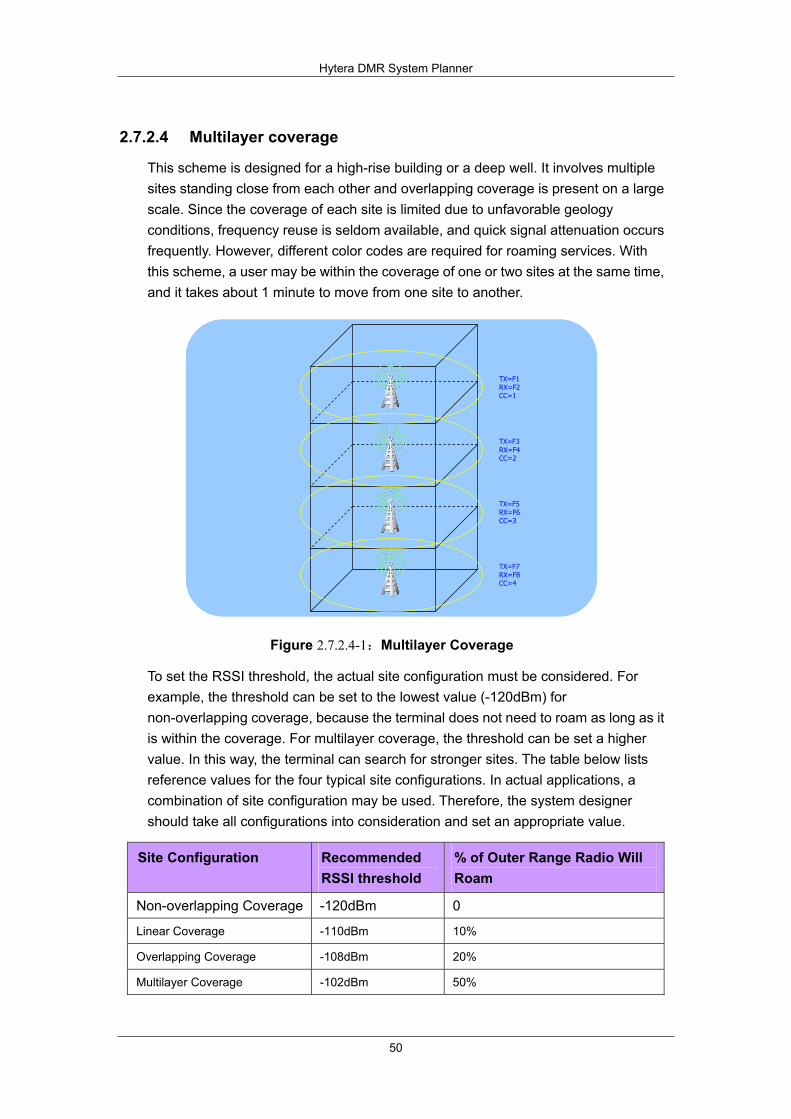
Hytera DMR System Planner
50
2.7.2.4 Multilayer coverage
This scheme is designed for a high-rise building or a deep well. It involves multiple sites standing close from each other and overlapping coverage is present on a large scale. Since the coverage of each site is limited due to unfavorable geology conditions, frequency reuse is seldom available, and quick signal attenuation occurs frequently. However, different color codes are required for roaming services. With this scheme, a user may be within the coverage of one or two sites at the same time, and it takes about 1 minute to move from one site to another.
TX=F1RX=F2CC=1
TX=F3RX=F4CC=2
TX=F5RX=F6CC=3
TX=F7RX=F8CC=4
TX=F1RX=F2CC=1
TX=F3RX=F4CC=2
TX=F5RX=F6CC=3
TX=F7RX=F8CC=4
Figure 2.7.2.4-1:Multilayer Coverage
To set the RSSI threshold, the actual site configuration must be considered. For example, the threshold can be set to the lowest value (-120dBm) for non-overlapping coverage, because the terminal does not need to roam as long as it is within the coverage. For multilayer coverage, the threshold can be set a higher value. In this way, the terminal can search for stronger sites. The table below lists reference values for the four typical site configurations. In actual applications, a combination of site configuration may be used. Therefore, the system designer should take all configurations into consideration and set an appropriate value.
Site Configuration Recommended RSSI threshold
% of Outer Range Radio Will Roam
Non-overlapping Coverage -120dBm 0
Linear Coverage -110dBm 10%
Overlapping Coverage -108dBm 20%
Multilayer Coverage -102dBm 50%
Hytera DMR System Planner
51
Please note that the above RSSI thresholds assume the outbound and inbound RF coverage of the system is balanced. In other words, when the terminal is within good outbound coverage of the repeater, the terminal’s inbound transmission can reach the repeater. As the roaming algorithm uses outbound transmission to decide when to roam, the terminal cannot roam in an unbalanced system even though it cannot reach the repeater. In this way, the transmission from the terminal cannot reach the repeater and so cannot be repeated.
The solution to this problem is to reduce the outbound TX power of the repeater, so as to shorten the outbound coverage. In this way, the terminal can send successfully as long as it can receive successfully. If reducing the outbound TX power is not desirable, set the RSSI threshold to a value higher than the recommended one, to force the terminal to roam even within good signal coverage. The threshold may be different for portable terminals and mobile terminals because they have different TX power and therefore different inbound coverage. The portable terminal may need a higher RSSI threshold than the mobile terminals.
Please note that each roam list is configured with a threshold value. This means if unbalance exists in one site rather than in the other site, it may be difficult to find an appropriate threshold value for both sites.
2.7.3 Setting Beacon Duration and Beacon Interval
If no activity is present in the system, the repeater will go to the sleep state. In this case, the terminal cannot detect signal strength via auto site roaming, preventing from selecting the strongest site. For this reason, the repeater should be configured to send beacons when no activity or interference is present in the system. During such period, the terminal decides when to roam in accordance with the strength of the beacon. If it does not receive any beacon within a predefined period, it will suppose that it is out of the coverage and start roaming.
The beacon duration and beacon interval are configurable via the CPS. The former can be configured in the repeater only, while the latter can be configured in the repeater and the terminal.
The beacon duration depends on the number of sites in the system and therefore in the roam list, while the interval depends on how quickly the terminal roams to another site.
The ratio of the beacon duration to the beacon interval equates to how often the repeater transmits (i.e. beacon transmission ratio) in the case of no inbound activities. This ratio is not configured for the system directly, but it is an important tip for setting the beacon duration and beacon interval. On a shared frequency, the transmission ratio for beacons should be kept low (target ratio: 5%-10%). In other words, the beacon interval should be increased accordingly if the beacon duration is

Hytera DMR System Planner
52
increased.
If the beacon duration is very short, it may be difficult for the terminal to detect it. This is especially true if there are more sites. If the terminal detects a specific site at longer intervals, it is more likely for the terminal to miss the beacon. Typically, a user is within the coverage of no more than four sites at any given time. Therefore even with a large roam list, most of the sites have no activity and can be detected quickly. However, interference may occur if many sites share frequencies.
Note: The nearest site will be detected first because the sites are ordered in accordance with signal strength in the roam list. If a user moves to a site that is not visited recently, the first roam may take a long time. Once the site is detected, it will be moved to the front of the roam list. To improve the possibility of receiving the beacon, the beacon duration should be increased. It is safer to have a beacon duration longer than shorter. Please note if the beacon duration is increased, the beacon interval will accordingly be increased to satisfy the beacon transmission ratio.
The beacon interval controls how quickly the terminal can roam to a site or away from a site when no activity is present in the system. When roaming with no system activity, the terminal needs a beacon to roam to a new site. If the repeater beacon is sent every one minute, the terminal may be one minute deep into the site before it sees the site and roams to it. Similarly, when roaming with no system activity, the terminal may be one minute outside of the site before it attempts to roam. The influence of this value often changes based on how quickly the user is traveling. For example, a vehicle driving at 60 miles per hour can cover a mile a minute, and so will be one mile into or out of a site before roaming. This is ideal for non-overlapping coverage and linear coverage. For overlapping coverage, the beacon interval should be shorter because the leaving and entering of sites should be quicker. Please note that if a user transmits before the beacon is detected via auto site roaming, the terminal will try to revive the site repeater.
A one minute beacon interval may be proper for walking users if the sites are not very close like in the “Multilayer Coverage” example. In this case, a user in an elevator may move fast between sites. The one minute beacon interval may be improper, because it may be longer than the duration that the user needs to move from the floor to the top. Hence, it is better to set the beacon interval to 20s. Please note that the 5% beacon transmission ratio may not be achievable for a system with multiple repeaters. In this case, the system designer may either decide to abandon this target ratio since indoor coverage usually does not propagate very far, or decrease the beacon duration. The table below lists recommended beacon durations and beacon intervals (8% beacon transmission ratio) for a varying number of sites. The default values for beacon duration and beacon interval are 4.32s and 60s respectively.
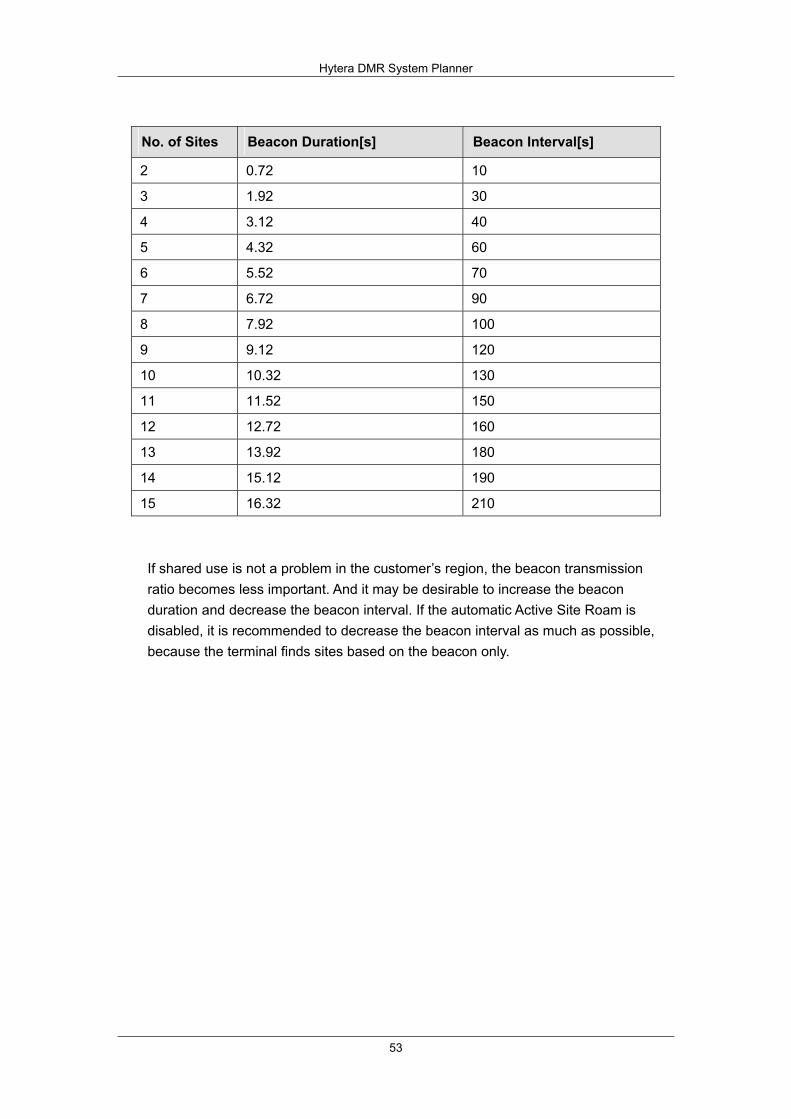
Hytera DMR System Planner
53
No. of Sites Beacon Duration[s] Beacon Interval[s]
2 0.72 10
3 1.92 30
4 3.12 40
5 4.32 60
6 5.52 70
7 6.72 90
8 7.92 100
9 9.12 120
10 10.32 130
11 11.52 150
12 12.72 160
13 13.92 180
14 15.12 190
15 16.32 210
If shared use is not a problem in the customer’s region, the beacon transmission ratio becomes less important. And it may be desirable to increase the beacon duration and decrease the beacon interval. If the automatic Active Site Roam is disabled, it is recommended to decrease the beacon interval as much as possible, because the terminal finds sites based on the beacon only.
Hytera DMR System Planner
54
2.7.4 Performance while Roaming
Please note that roaming may cause performance degradations. Therefore, the RSSI threshold and the terminal’s Site Lock must be set appropriately when not in mobile status. The degradations are similar to what the terminal will experience during scanning. Degradation may occur in the following:
Late entry to voice transmission Longer preamble required for control message and data Increased setup time for Confirmed Private Call Group Call Time to Talk Permit may increase if auto site roaming is required
During roaming, the terminal will temporarily leave the current home channel and detect other sites (similar to scan). This means the terminal may not be present on the master site when a call starts. After detecting every other site, the terminal will detect the master site to minimize the time away from it. This is similar to the scanning order for a priority member.
If the current master site cannot be revived, the terminal will try to locate another site via the automatic active site roaming. When the terminal tries to revive other sites, the user must wait. This increase in time will be recognized as an increase in the time from PTT to receiving the Talk Permit Tone. This will not occur often if the beacon interval for the repeater is appropriately set.
It is expected that the value that the Roaming feature adds is worth these performance degradations. The beacon interval and the RSSI threshold should be appropriately set to minimize the time the terminal needs to search for a site.
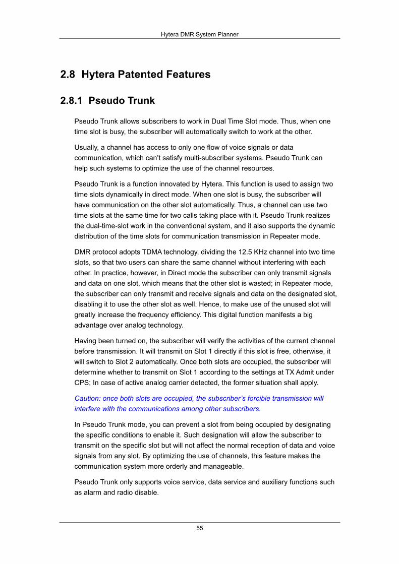
Hytera DMR System Planner
55
2.8 Hytera Patented Features
2.8.1 Pseudo Trunk
Pseudo Trunk allows subscribers to work in Dual Time Slot mode. Thus, when one time slot is busy, the subscriber will automatically switch to work at the other.
Usually, a channel has access to only one flow of voice signals or data communication, which can’t satisfy multi-subscriber systems. Pseudo Trunk can help such systems to optimize the use of the channel resources.
Pseudo Trunk is a function innovated by Hytera. This function is used to assign two time slots dynamically in direct mode. When one slot is busy, the subscriber will have communication on the other slot automatically. Thus, a channel can use two time slots at the same time for two calls taking place with it. Pseudo Trunk realizes the dual-time-slot work in the conventional system, and it also supports the dynamic distribution of the time slots for communication transmission in Repeater mode.
DMR protocol adopts TDMA technology, dividing the 12.5 KHz channel into two time slots, so that two users can share the same channel without interfering with each other. In practice, however, in Direct mode the subscriber can only transmit signals and data on one slot, which means that the other slot is wasted; in Repeater mode, the subscriber can only transmit and receive signals and data on the designated slot, disabling it to use the other slot as well. Hence, to make use of the unused slot will greatly increase the frequency efficiency. This digital function manifests a big advantage over analog technology.
Having been turned on, the subscriber will verify the activities of the current channel before transmission. It will transmit on Slot 1 directly if this slot is free, otherwise, it will switch to Slot 2 automatically. Once both slots are occupied, the subscriber will determine whether to transmit on Slot 1 according to the settings at TX Admit under CPS; In case of active analog carrier detected, the former situation shall apply.
Caution: once both slots are occupied, the subscriber’s forcible transmission will interfere with the communications among other subscribers.
In Pseudo Trunk mode, you can prevent a slot from being occupied by designating the specific conditions to enable it. Such designation will allow the subscriber to transmit on the specific slot but will not affect the normal reception of data and voice signals from any slot. By optimizing the use of channels, this feature makes the communication system more orderly and manageable.
Pseudo Trunk only supports voice service, data service and auxiliary functions such as alarm and radio disable.
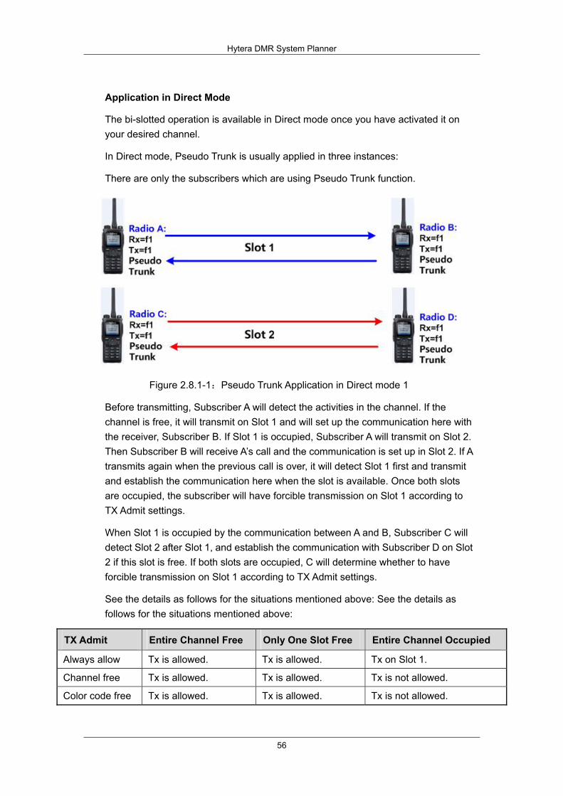
Hytera DMR System Planner
56
Application in Direct Mode
The bi-slotted operation is available in Direct mode once you have activated it on your desired channel.
In Direct mode, Pseudo Trunk is usually applied in three instances:
There are only the subscribers which are using Pseudo Trunk function.
Figure 2.8.1-1:Pseudo Trunk Application in Direct mode 1
Before transmitting, Subscriber A will detect the activities in the channel. If the channel is free, it will transmit on Slot 1 and will set up the communication here with the receiver, Subscriber B. If Slot 1 is occupied, Subscriber A will transmit on Slot 2. Then Subscriber B will receive A’s call and the communication is set up in Slot 2. If A transmits again when the previous call is over, it will detect Slot 1 first and transmit and establish the communication here when the slot is available. Once both slots are occupied, the subscriber will have forcible transmission on Slot 1 according to TX Admit settings.
When Slot 1 is occupied by the communication between A and B, Subscriber C will detect Slot 2 after Slot 1, and establish the communication with Subscriber D on Slot 2 if this slot is free. If both slots are occupied, C will determine whether to have forcible transmission on Slot 1 according to TX Admit settings.
See the details as follows for the situations mentioned above: See the details as follows for the situations mentioned above:
TX Admit Entire Channel Free Only One Slot Free Entire Channel Occupied
Always allow Tx is allowed. Tx is allowed. Tx on Slot 1.
Channel free Tx is allowed. Tx is allowed. Tx is not allowed.
Color code free Tx is allowed. Tx is allowed. Tx is not allowed.
Hytera DMR System Planner
57
There are subscribers using Pseudo Trunk and a single time slot respectively.
Figure 2.8.1-2:Pseudo Trunk Application in Direct mode 2
Pseudo Trunk supports the communication with non-Pseudo Trunk subscriber, which means that a subscriber with Pseudo Trunk can have normal communication with a subscriber with a conventional single time slot on the same channel.
As is shown in Figure 2-2, if both Subscriber A and B select Slot 1, they can only have communication in Slot 1. Both Subscriber C and D select Pseudo Trunk, so they can have communication in any time slot on the channel. In Pseudo Trunk mode, the subscriber will take Slot 1 as its default Tx slot. If there are activities on the channel, Slot 1 must be occupied. Thus, Subscriber A and B will have their transmissions according to TX Admit settings if they are to establish communication now.
If they are to call another subscriber in Pseudo Trunk mode, they can only transmit in Slot 1. If the object subscriber is free, Subscriber A or B will transmit on Slot 1. Whether to transmit depends on the status of the channel and TX Admit settings of the transmitter itself. If the called Pseudo Trunk subscriber is busy, it will not response to the call.
The Pseudo Trunk subscriber can only call Subscriber A and B which are in a single time slot in Slot 1, otherwise, there will be no response at all. However, the Pseudo Trunk subscriber is unable to ensure that it must transmit on Slot 1, so you can consider designating the Tx slot for it. After you designate the Tx slot, the Pseudo Trunk subscriber can only transmit on that slot but can receive signals and data from both slots.
Calls between Pseudo Trunk subscribers can take place in any time slot. However, if the called subscriber is busy, it will not have any response. If the called subscriber is in transmitting state, the call must be made in its current slot so that the communication can be set up.
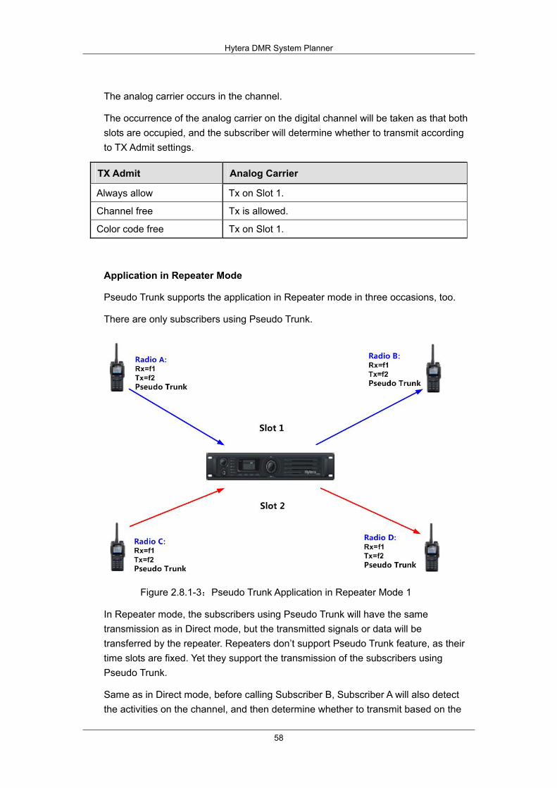
Hytera DMR System Planner
58
The analog carrier occurs in the channel.
The occurrence of the analog carrier on the digital channel will be taken as that both slots are occupied, and the subscriber will determine whether to transmit according to TX Admit settings.
TX Admit Analog Carrier
Always allow Tx on Slot 1.
Channel free Tx is allowed.
Color code free Tx on Slot 1.
Application in Repeater Mode
Pseudo Trunk supports the application in Repeater mode in three occasions, too.
There are only subscribers using Pseudo Trunk.
Figure 2.8.1-3:Pseudo Trunk Application in Repeater Mode 1
In Repeater mode, the subscribers using Pseudo Trunk will have the same transmission as in Direct mode, but the transmitted signals or data will be transferred by the repeater. Repeaters don’t support Pseudo Trunk feature, as their time slots are fixed. Yet they support the transmission of the subscribers using Pseudo Trunk.
Same as in Direct mode, before calling Subscriber B, Subscriber A will also detect the activities on the channel, and then determine whether to transmit based on the

Hytera DMR System Planner
59
status of the slots. If its Tx slot is designated, A will detect the status of the Tx slot first, and then determine whether to transmit according to TX Admit settings. If the channel is free, and Subscriber A doesn’t have a designated Tx slot, Slot 1 will be the default Tx slot for A to establish the communication with B. If Subscriber C is going to call D now, it will find Slot 1 busy and have the transmission and communication to D in Slot 2.
If the whole channel is occupied when the subscriber is transmitting, the subscriber will take Slot 1 as the default Tx slot and determine whether to transmit according to TX Admit settings. The transmission process is the same as in Direct mode, and the repeater is used for transferring the signals or data.
See the following details of transmission:
TX Admit Entire Channel Free Only One Slot Free Entire Channel Occupied
Always allow Tx is allowed. Tx is allowed. Tx on Slot 1.
Channel free Tx is allowed. Tx is allowed. Tx is not allowed.
Color code free Tx is allowed. Tx is allowed. Tx is not allowed.
There are both subscribers using Pseudo Trunk and a single time slot respectively.
Figure 2.8.1-4:Pseudo Trunk Application in Repeater Mode 2
In this circumstance, the subscriber with single time slot can only use its own designated time slot, and the subscriber with Pseudo Trunk can use any slot for transmission if it doesn’t have designated Tx slot. As the figure above shows, the single-time-slot Subscriber A and B can only use Slot 1, while pseudo-trunk Subscriber C and D can use Slot 1 and Slot 2, but will take Slot 1 as their default Tx slot. Thus, Slot 1 will have big probability to be occupied. Once this happens, the pseudo-trunk subscribers will determine whether to transmit according to their TX

Hytera DMR System Planner
60
Admit settings.
Comparatively, slot 2 will have small probability to be occupied, as it will only be selected by the subscriber using Pseudo Trunk when Slot 1 is busy, so we suggest you to designate Slot 2 for part of the pseudo-trunk subscribers.
Repeater mode has a difference from Direct mode that the signals and data are transferred by the repeater with fixed slot. The repeater itself doesn’t support Pseudo Trunk, but it won’t affect the use of Pseudo Trunk by the subscribers.
The analog carrier occurs in the channel.
The subscriber will take the occurrence of the analog carrier on the digital channel as that both slots are occupied, and determine whether to transmit according to TX Admit settings.
TX Admit Analog Carrier
Always allow Tx on Slot 1.
Channel free Tx is allowed.
Color code free Tx on Slot 1.
Designed TX Slot application Introduction
You can designate the Tx slot for Pseudo Trunk through the CPS, and then the subscriber will only transmit on that slot but can receive signals or data in both slots.
If you don’t designate any Tx slot, the subscriber will transmit on a free slot and take Slot 1 as the default one.
Designating the Tx Slot for Direct Mode
Set to “None” and the subscriber will select a free slot for transmission.
If no carrier or analog signal is detected, the subscriber will transmit in Slot 1; in case of activities in the channel, the first used slot is taken as Slot 1, and if Slot 1 is in transmission, the new transmission will be made in Slot 2. when the subscriber receives a call, it will call back by PTT in the slot where the call is received. Once both slots are occupied or interfered by analog signals, the subscriber will determine whether to transmit according to TX Admit.
Set to “Slot 1”: The subscriber will transmit in Slot 1 in Pseudo Trunk mode, except for the response to an incoming call.
If no carrier or analog signal is detected, the transmission will be done in Slot 1; in
Hytera DMR System Planner
61
case of activities on the channel, the first used slot will be taken as Slot 1. When the subscriber receives the call in Slot 1, it will call back in Slot 1, too. If Slot 1 is occupied, the subscriber will determine whether to transmit according to TX Admit settings.
When TX Admit is set to “Allow”, the subscriber will transmit in Slot 1.
When TX Admit is set to “Color Code Free”, and a call with the same color code is made in Slot 1, the transmission will be refused here, otherwise, it is allowed.
When TX Admit is set to “Channel Free”, and a carrier is detected in Slot 1, transmission will be refused here, otherwise, it is allowed.
Set to “Slot 2”: The subscriber will transmit in Slot 2 in Pseudo Trunk mode, except for the response to an in coming call.
If no carrier or analog signal is detected, Slot 1 will be taken as the default slot for transmission. In case of activities on the channel, the first used slot is Slot 1. Thus, the subscriber will determine whether to transmit in Slot 2 according to TX Admit settings.
When TX Admit is set to “Allow”, the subscriber will transmit in Slot 2.
When TX Admit is set to “Color Code Free”, and a call with the same color code is made in Slot 2, the transmission will be refused here, otherwise, it is will be allowed.
When TX Admit is set to “Channel Free”, and a carrier is detected in Slot 2, the transmission will be refused here, otherwise, it is allowed.
Designating the Tx Slot for Repeater Mode
Set to “None” and the subscriber will select a free slot for transmission.
If no carrier or analog interference is detected, the subscriber will transmit on Slot 1 after the repeater is activated; if there are activities on Slot 1, the transmission will be made on Slot 2; if Slot 2 is occupied, the subscriber will make a call again on Slot 1. If the subscriber receives a call, it will call back by PTT on the slot where the call is received. Once both slots are occupied or interfered by analog signals, the subscriber will determine whether to transmit according to TX Admit.
Set to “Slot 1”: The subscriber will transmit on Slot 1 in Pseudo Trunk mode, except for the response.
If no carrier or analog interference is detected, the subscriber will transmit on Slot 1 after the repeater is activated; after receiving a call, the subscriber will respond on the slot where the call is received; once Slot 1 or both slots are occupied, the subscriber will determine whether to transmit on Slot 1 according to TX Admit.
Hytera DMR System Planner
62
When TX Admit is set to “Allow”, the subscriber will transmit on Slot 1.
When TX Admit is set to “Color Code Free” or “Channel Free”, and Slot 1 is busy, the transmission will be refused.
Set to “Slot 2”: The subscriber will transmit on Slot 2 in Pseudo Trunk mode, except for the response.
If no carrier or analog interference is detected, the subscriber will transmit on Slot 2, the default slot, after the repeater is activated; when receiving a call, the subscriber will respond on the slot where the call is received; once Slot 2 or both slots are occupied, the subscriber will determine whether to transmit on Slot 2 according to TX Admit.
When TX Admit is set to “Allow”, the subscriber will transmit on Slot 2.
When TX Admit is set to “Color Code Free” or “Channel Free”, and Slot 2 is busy, the transmission will be refused.
2.8.2 Priority Interrupt
Priority Interrupt allows a subscriber to make the channel free for its own voice or data service by interrupting an ongoing call on the channel or terminating the services of a repeater such as Call Hold and Remote Monitor.
Priority Interrupt is especially useful when the channel is busy. With this feature, the user can interrupt the active call to transmit his voice signals or data on the channel. This feature is also used for channel management to optimize channel efficiency.
Priority Interrupt allows a subscriber to make the channel free for its own voice or data services by interrupting an ongoing call on the channel or terminating the services of a repeater such as Call Hold and Remote Monitor. This feature can only interrupt the voice services but not data. Thus, the ongoing data services such as GPS or short message on the channel will not be affected.
In Pseudo Trunk mode, the channel has two time slots, which can be used to receive data and voice services separately at the same time. When one slot is occupied, the subscriber can transmit the Priority Interrupt command in the other slot, and the active call on the channel will be interrupted when the target subscriber responds to the command.
Before transmitting the Priority Interrupt command, the subscriber will detect the channel status. If Slot 1 is busy with a call and Slot 2 is free, the command will be transmitted in Slot 2. Then, after the target subscriber receives and decodes the command in Slot 2, the ongoing call in Slot 1 will be interrupted, so the interrupting subscriber can transmit its own services in Slot 1. The subscriber which enables
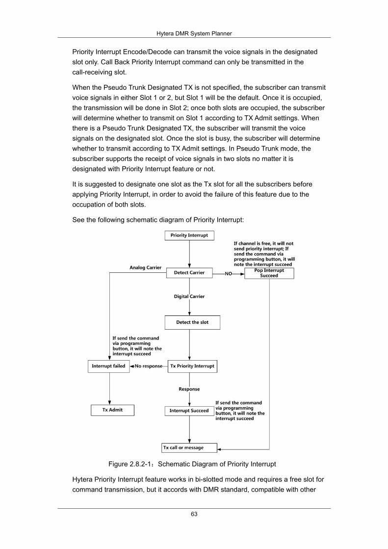
Hytera DMR System Planner
63
Priority Interrupt Encode/Decode can transmit the voice signals in the designated slot only. Call Back Priority Interrupt command can only be transmitted in the call-receiving slot.
When the Pseudo Trunk Designated TX is not specified, the subscriber can transmit voice signals in either Slot 1 or 2, but Slot 1 will be the default. Once it is occupied, the transmission will be done in Slot 2; once both slots are occupied, the subscriber will determine whether to transmit on Slot 1 according to TX Admit settings. When there is a Pseudo Trunk Designated TX, the subscriber will transmit the voice signals on the designated slot. Once the slot is busy, the subscriber will determine whether to transmit according to TX Admit settings. In Pseudo Trunk mode, the subscriber supports the receipt of voice signals in two slots no matter it is designated with Priority Interrupt feature or not.
It is suggested to designate one slot as the Tx slot for all the subscribers before applying Priority Interrupt, in order to avoid the failure of this feature due to the occupation of both slots.
See the following schematic diagram of Priority Interrupt:
Figure 2.8.2-1:Schematic Diagram of Priority Interrupt
Hytera Priority Interrupt feature works in bi-slotted mode and requires a free slot for command transmission, but it accords with DMR standard, compatible with other
Hytera DMR System Planner
64
DMR features. When both slots are occupied, the subscriber will have an impolite transmission of Priority Interrupt command to increase its success rate. If the interruption fails, the system will give the prompt “Channel busy” or a request for random hold off.
After Priority Interrupt command is transmitted, services except call back will be transmitted in the designated Tx slot under Pseudo Trunk. The Call Back Priority Interrupt will be transmitted in the call-receiving slot.
There are six means of Priority Interrupt:
Interrupt by shortcuts: To transmit this command via a programmable key to interrupt the on-going call on the channel.
Call Back Priority Interrupt: When receiving a call, the user is allowed to interrupt the call to call back by pressing PTT key.
Message Priority Interrupt: To enable Priority Interrupt feature by message, in order to interrupt the ongoing call and send the message.
Caution: Same as short message, GPS message can also trigger Message Priority Interrupt provided that the parameter of GPS Revert Channel is enabled. However, it is not suggested to set this command in GPS Revert Channel, so that normal communications on the channel will not be disturbed.
Emergency Priority Interrupt: To ensure the timely and uninterrupted emergency alarm, users are allowed to interrupt the active call by Emergency Alarm.
Radio Disable Priority Interrupt: When the channel is busy, the subscriber is allowed to transmit the Radio Disable command to trigger the interruption to the ongoing call, so as to finish the disabling operation.
All Call Priority Interrupt: When the channel is busy, the subscriber is allowed to transmit the All Call request to trigger the interruption to the ongoing call via the command, in order to finish the All Call request.
To use Priority Interrupt feature normally, users need to configure its related parameters at TX/RX end properly according to actual requirements. Priority Interrupt, a channel-specific feature, is only operable on the channel which enables it. Besides enabling the corresponding Priority Interrupts for different uses, you also have to select Priority Interrupt Encode and Priority Interrupt Decode options for the channel you use.
To carry out Priority Interrupt function, you need to set parameters for the interrupting subscriber and the interrupted one respectively.

Hytera DMR System Planner
65
Shortcut Application
Configuration Requirements:
1. The interrupting subscriber, Subscriber B, must enable Priority Interrupt Encode on the current channel and set the programmable key corresponding to the function. e.g.: Set SK1 corresponding to Priority Interrupt.
2. Subscriber A, the interrupted subscriber, must have the enabled Priority Interrupt Decode option on the current channel.
3. Both the subscribers are on the same channel, using Pseudo Trunk and meeting the requirements on TX Admit settings.
See Figure: 2.8.2-2 for the example.
Figure 2.8.2-2: Shortcut Application
1. Subscriber A is transmitting voice signals in communication with B and C in Group Call 1.
2. Subscriber B transmits Priority Interrupt command by SK1.
3. After Subscriber A receives and decodes the command, the call will be interrupted and the prompt, “Call interrupted”, will pop up in its main interface. Also, Subscriber C will get a notice that the call is over, and B will be noted “Interrupt Success”.
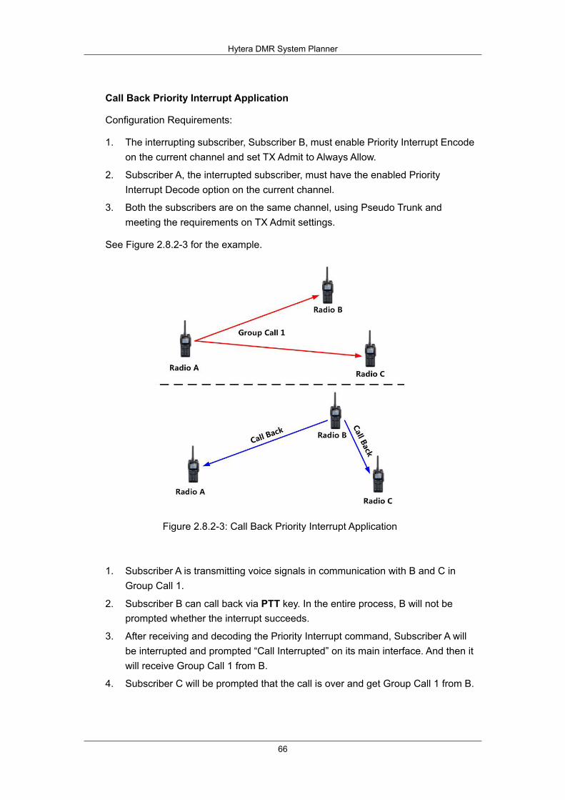
Hytera DMR System Planner
66
Call Back Priority Interrupt Application
Configuration Requirements:
1. The interrupting subscriber, Subscriber B, must enable Priority Interrupt Encode on the current channel and set TX Admit to Always Allow.
2. Subscriber A, the interrupted subscriber, must have the enabled Priority Interrupt Decode option on the current channel.
3. Both the subscribers are on the same channel, using Pseudo Trunk and meeting the requirements on TX Admit settings.
See Figure 2.8.2-3 for the example.
Figure 2.8.2-3: Call Back Priority Interrupt Application
1. Subscriber A is transmitting voice signals in communication with B and C in Group Call 1.
2. Subscriber B can call back via PTT key. In the entire process, B will not be prompted whether the interrupt succeeds.
3. After receiving and decoding the Priority Interrupt command, Subscriber A will be interrupted and prompted “Call Interrupted” on its main interface. And then it will receive Group Call 1 from B.
4. Subscriber C will be prompted that the call is over and get Group Call 1 from B.
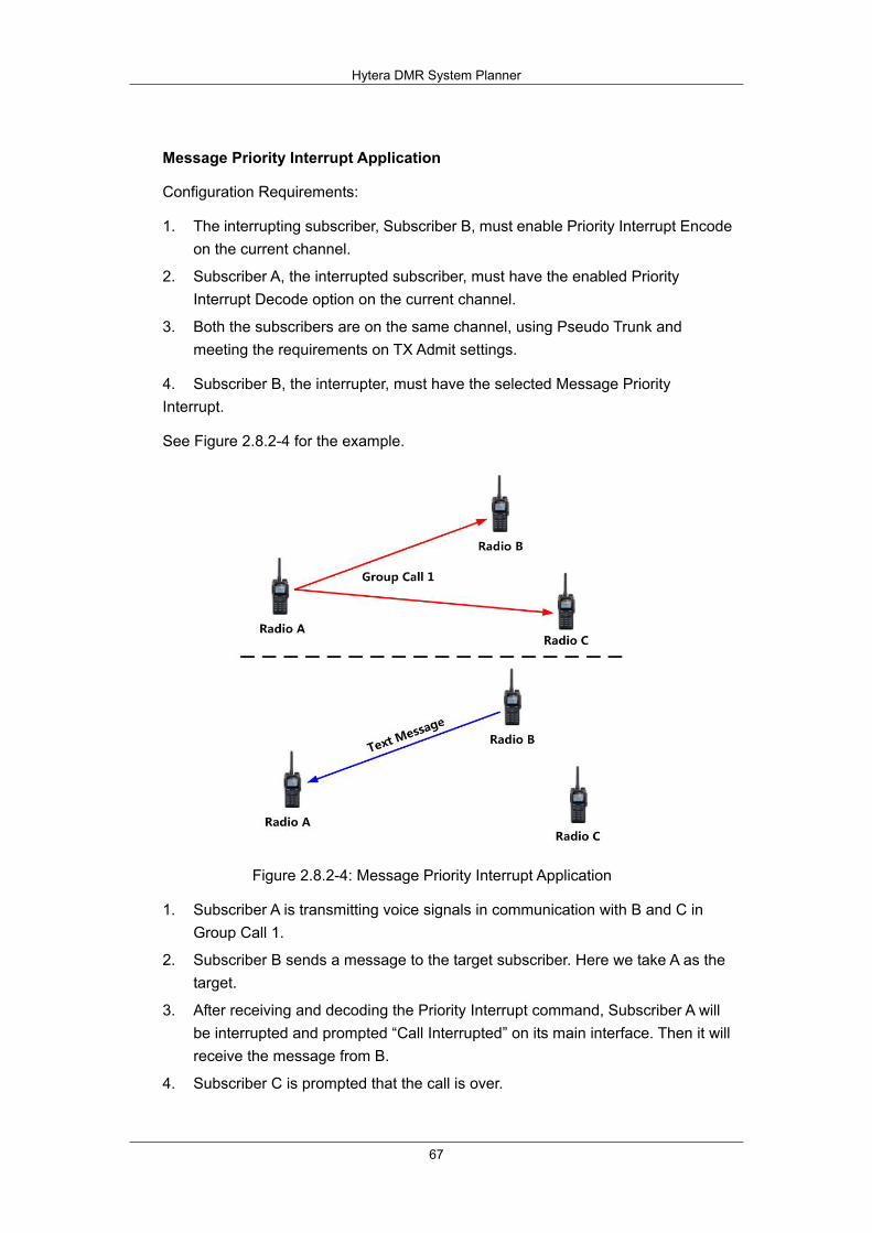
Hytera DMR System Planner
67
Message Priority Interrupt Application
Configuration Requirements:
1. The interrupting subscriber, Subscriber B, must enable Priority Interrupt Encode on the current channel.
2. Subscriber A, the interrupted subscriber, must have the enabled Priority Interrupt Decode option on the current channel.
3. Both the subscribers are on the same channel, using Pseudo Trunk and meeting the requirements on TX Admit settings.
4. Subscriber B, the interrupter, must have the selected Message Priority Interrupt.
See Figure 2.8.2-4 for the example.
Figure 2.8.2-4: Message Priority Interrupt Application
1. Subscriber A is transmitting voice signals in communication with B and C in Group Call 1.
2. Subscriber B sends a message to the target subscriber. Here we take A as the target.
3. After receiving and decoding the Priority Interrupt command, Subscriber A will be interrupted and prompted “Call Interrupted” on its main interface. Then it will receive the message from B.
4. Subscriber C is prompted that the call is over.
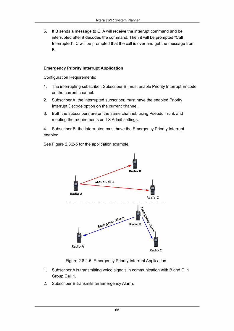
Hytera DMR System Planner
68
5. If B sends a message to C, A will receive the interrupt command and be interrupted after it decodes the command. Then it will be prompted “Call Interrupted”. C will be prompted that the call is over and get the message from B.
Emergency Priority Interrupt Application
Configuration Requirements:
1. The interrupting subscriber, Subscriber B, must enable Priority Interrupt Encode on the current channel.
2. Subscriber A, the interrupted subscriber, must have the enabled Priority Interrupt Decode option on the current channel.
3. Both the subscribers are on the same channel, using Pseudo Trunk and meeting the requirements on TX Admit settings.
4. Subscriber B, the interrupter, must have the Emergency Priority Interrupt enabled.
See Figure 2.8.2-5 for the application example.
Figure 2.8.2-5: Emergency Priority Interrupt Application
1. Subscriber A is transmitting voice signals in communication with B and C in Group Call 1.
2. Subscriber B transmits an Emergency Alarm.
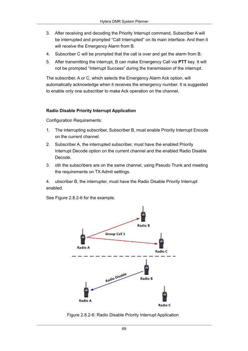
Hytera DMR System Planner
69
3. After receiving and decoding the Priority Interrupt command, Subscriber A will be interrupted and prompted “Call Interrupted” on its main interface. And then it will receive the Emergency Alarm from B.
4. Subscriber C will be prompted that the call is over and get the alarm from B.
5. After transmitting the interrupt, B can make Emergency Call via PTT key. It will not be prompted “Interrupt Success” during the transmission of the interrupt.
The subscriber, A or C, which selects the Emergency Alarm Ack option, will automatically acknowledge when it receives the emergency number. It is suggested to enable only one subscriber to make Ack operation on the channel.
Radio Disable Priority Interrupt Application
Configuration Requirements:
1. The interrupting subscriber, Subscriber B, must enable Priority Interrupt Encode on the current channel.
2. Subscriber A, the interrupted subscriber, must have the enabled Priority Interrupt Decode option on the current channel and the enabled Radio Disable Decode.
3. oth the subscribers are on the same channel, using Pseudo Trunk and meeting the requirements on TX Admit settings.
4. ubscriber B, the interrupter, must have the Radio Disable Priority Interrupt enabled.
See Figure 2.8.2-6 for the example.
Figure 2.8.2-6: Radio Disable Priority Interrupt Application
Hytera DMR System Planner
70
1. Subscriber A is transmitting voice signals in communication with B and C in Group Call 1.
2. Subscriber B initiates the Radio Disable, targeting at Subscriber A or another. The target subscriber must select Radio Disable Priority Interrupt option apart from setting the Priority Interrupt parameters.
3. After receiving and decoding the Priority Interrupt command, Subscriber A will be interrupted and prompted “Call Interrupted” on its main interface. Then it will receive the Radio Disable command from B, and be disabled after decoding the command.
4. Subscriber C is prompted that the call is over.
5. If B doesn’t receive the ACK from A, it will try to transmit the Radio Disable command again, but not the Priority Interrupt one.
6. If B sends the Radio Disable command to C, A will receive the interruption command and be interrupted after it decodes the command. Then it will be prompted “Call Interrupted”. C will be prompted that the call is over, get the Radio Disable command from B and be disabled after decoding the command.

Hytera DMR System Planner
71
All Call Priority Interrupt Application
Configuration Requirements:
1. he interrupting subscriber, Subscriber B, must enable Priority Interrupt Encode on the current channel.
2. ubscriber A, the interrupted subscriber, must have the Priority Interrupt Decode option and the Radio Disable Decode enabled on the current channel.
3. oth the subscribers are on the same channel, using Pseudo Trunk and meeting the requirements on TX Admit settings.
4. ubscriber B, the interrupter, must have the All Call Priority Interrupt enabled.
See Figure 2.8.2-7 for the example.
Figure 2.8.2-7:All Call Priority Interrupt Application
1. Subscriber A is transmitting voice signals in communication with B and C in Group Call 1.
2. Subscriber B initiates All Call. During its transmission, B will not be prompted any information on interrupt.
3. After receiving and decoding the Priority Interrupt command, Subscriber A will be interrupted and prompted “Call Interrupted” on its main interface. And then it will receive the All Call request from B and start communication.
4. C will be prompted that the call is over, then receive the All Call from B and start communication.
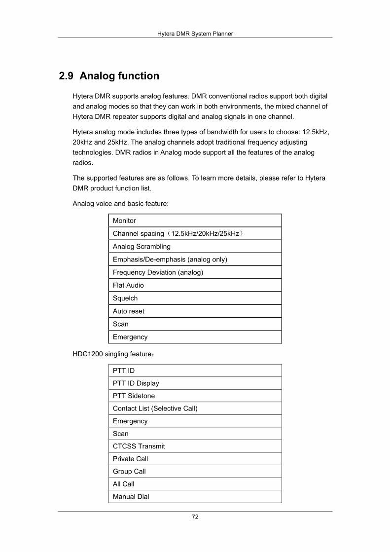
Hytera DMR System Planner
72
2.9 Analog function
Hytera DMR supports analog features. DMR conventional radios support both digital and analog modes so that they can work in both environments, the mixed channel of Hytera DMR repeater supports digital and analog signals in one channel.
Hytera analog mode includes three types of bandwidth for users to choose: 12.5kHz, 20kHz and 25kHz. The analog channels adopt traditional frequency adjusting technologies. DMR radios in Analog mode support all the features of the analog radios.
The supported features are as follows. To learn more details, please refer to Hytera DMR product function list.
Analog voice and basic feature:
Monitor
Channel spacing(12.5kHz/20kHz/25kHz)
Analog Scrambling
Emphasis/De-emphasis (analog only)
Frequency Deviation (analog)
Flat Audio
Squelch
Auto reset
Scan
Emergency
HDC1200 singling feature:
PTT ID
PTT ID Display
PTT Sidetone
Contact List (Selective Call)
Emergency
Scan
CTCSS Transmit
Private Call
Group Call
All Call
Manual Dial

Hytera DMR System Planner
73
Digital of Squelch (DOS)
Five tone singling feature:
User Mode (Advanced and Basic)
Multi-call Address (manual dial)
Multi-call Status (manual dial)
Standard System of ZVEI1, ZVEI2, ZVEI3, CCIR1, CCIR2, CCIR3, EEA, EIA
PTT ID
Smart Call
ACK1/Authorization (with ack only)
Call list
Private Call
Group Call
Two tone singling feature:
Contact list
Alias
Selective Call
Alert Call
Alert Call w/Voice
ACK
Clear to Transpond
Decode Format
Vibration

Hytera DMR System Planner
74
2.10 Back-to-Back
The “back-to-back” is a system solution based on accessory pin. It is used to achieve cross-band communication among analog and digital terminals. There are two methods of back-to-back solution provided by Hytera:
Back-to-back Mobile Radio Back-to-back Repeaters
2.10.1 Mobile Radio Accessory Pin
Input
On both analog and digital channels, the mobile radio can trigger or terminate the transmission via the accessory pin, and the audio signals to be transmitted will be sampled via the input pin as well.
Function Type Applicable Mode
Definition
EXT Mic PTT (via accessory PTT)
A fixed function
Analog and Digital
When a valid level is input, the mobile radio will trigger its external PTT and transmit the audio signal sampled from Codec. However, the transmission will be stopped in case of invalid level.
Tx Audio (via external MIC signal)
A fixed function
Analog and Digital
When the external PTT is enabled, the mobile radio will transmit the audio signals.
Output
On both analog channel and digital channels, the mobile radio can output (in level form) the status of call request as well as the call contents from the portable radio via the accessory pin. The definition of involved pins is given below:

Hytera DMR System Planner
75
Function Type Applicable Mode
Definition
Speaker Open Detect (for speaker detection)
Programmable Analog and Digital
When the speaker is detected unmuted, the mobile radio will output a valid level. However, it will output an invalid level when the speaker is muted.
Rx Audio Output (for audio output)
A fixed function
Analog and Digital
When any audio signal is received, the mobile radio will output such signal via the accessory pin.
2.10.2 Repeater Accessory Pin
Input
On both analog and digital channels, the repeater transmission can be triggered or terminated via the accessory pin, and the audio signals to be transmitted will be sampled via the input pin as well.
Function Type Applicable Mode
Definition
EXT Mic PTT Programmable Analog and Digital
When a valid level is input, the repeater will trigger its external PTT and transmit the audio signal sampled from Codec. However, the transmission will stop in case of invalid level.
Tx Audio A fixed function
Analog and Digital
When the external PTT is enabled, the repeater will transmit the audio signals.
Output
On both analog and digital channels, the repeater can output (in level form) the status of call request as well as the call content from a terminal via the accessory pin. The definition of involved pins is given below:
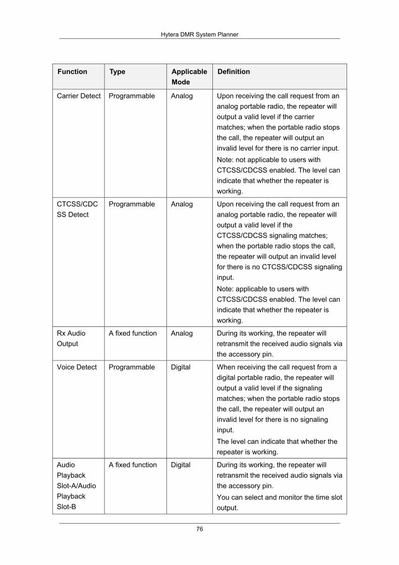
Hytera DMR System Planner
76
Function Type Applicable Mode
Definition
Carrier Detect Programmable Analog Upon receiving the call request from an analog portable radio, the repeater will output a valid level if the carrier matches; when the portable radio stops the call, the repeater will output an invalid level for there is no carrier input. Note: not applicable to users with CTCSS/CDCSS enabled. The level can indicate that whether the repeater is working.
CTCSS/CDCSS Detect
Programmable Analog Upon receiving the call request from an analog portable radio, the repeater will output a valid level if the CTCSS/CDCSS signaling matches; when the portable radio stops the call, the repeater will output an invalid level for there is no CTCSS/CDCSS signaling input. Note: applicable to users with CTCSS/CDCSS enabled. The level can indicate that whether the repeater is working.
Rx Audio Output
A fixed function Analog During its working, the repeater will retransmit the received audio signals via the accessory pin.
Voice Detect Programmable Digital When receiving the call request from a digital portable radio, the repeater will output a valid level if the signaling matches; when the portable radio stops the call, the repeater will output an invalid level for there is no signaling input. The level can indicate that whether the repeater is working.
Audio Playback Slot-A/Audio Playback Slot-B
A fixed function Digital During its working, the repeater will retransmit the received audio signals via the accessory pin. You can select and monitor the time slot output.

Hytera DMR System Planner
77
2.11 Hytera DMR Application Protocol
Hytera digital radio provides application interfaces for secondary development for third party partners besides its original functions. Hytera DMR Application Protocol (HDAP) is the general term of a series of application-layer protocols; it contains Radio Registration Service (RRS), Location Protocol (LP), Text Message Protocol (TMP), Radio Control Protocol (RCP), Telemetry Protocol (TP), and Data Transmit Protocol (DTP).
This protocol is designed to support voice, signalling and data communication on a point-to-point connection between distinct networks. HDAP Application (which is usually deployed in a PC) connects to the Dispatcher Station, which can be Mobile or Repeater, voice, signaling and data message are transmitted via IP network between application and Dispatcher Station, and through radio network between Dispatcher Station and DMR radios.
Hytera currently mainly provides DMR application applications as below:
Hytera Radio Registration Service Hytera Location Service Hytera Radio Control Service Hytera Text Message Service Hytera Data Transmission Service Hytera Telemetry Service Hytera Real-time Transport Service (Only for Repeater)
These DMR applications are enough to meet general applications. For better using Hytera digital radio, we have extended platform of PC interface based on DMR application applications which enables you to use and control the radio over the extended platform. You can connect Hytera radio system by this interface which provides more powerful application system. These DMR applications are achieved through the TCP/IP protocol, which bring flexible system networking.
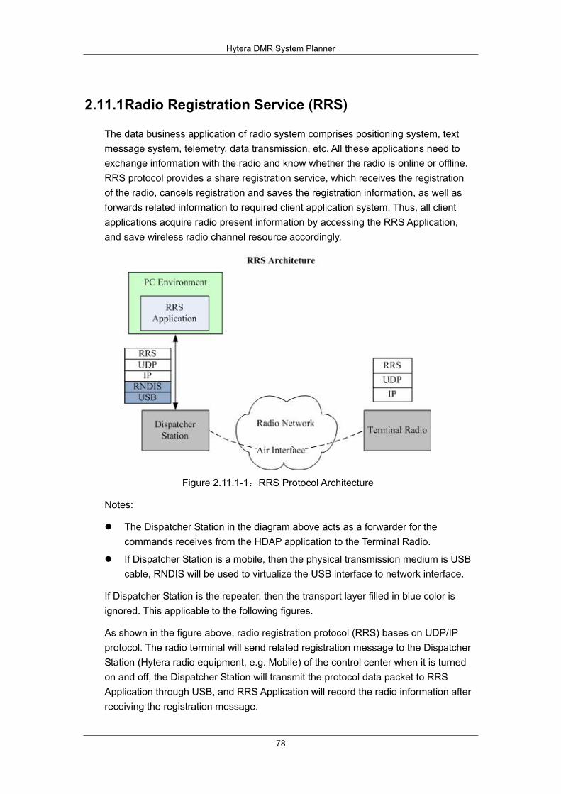
Hytera DMR System Planner
78
2.11.1 Radio Registration Service (RRS)
The data business application of radio system comprises positioning system, text message system, telemetry, data transmission, etc. All these applications need to exchange information with the radio and know whether the radio is online or offline. RRS protocol provides a share registration service, which receives the registration of the radio, cancels registration and saves the registration information, as well as forwards related information to required client application system. Thus, all client applications acquire radio present information by accessing the RRS Application, and save wireless radio channel resource accordingly.
Figure 2.11.1-1:RRS Protocol Architecture
Notes:
The Dispatcher Station in the diagram above acts as a forwarder for the commands receives from the HDAP application to the Terminal Radio.
If Dispatcher Station is a mobile, then the physical transmission medium is USB cable, RNDIS will be used to virtualize the USB interface to network interface.
If Dispatcher Station is the repeater, then the transport layer filled in blue color is ignored. This applicable to the following figures.
As shown in the figure above, radio registration protocol (RRS) bases on UDP/IP protocol. The radio terminal will send related registration message to the Dispatcher Station (Hytera radio equipment, e.g. Mobile) of the control center when it is turned on and off, the Dispatcher Station will transmit the protocol data packet to RRS Application through USB, and RRS Application will record the radio information after receiving the registration message.
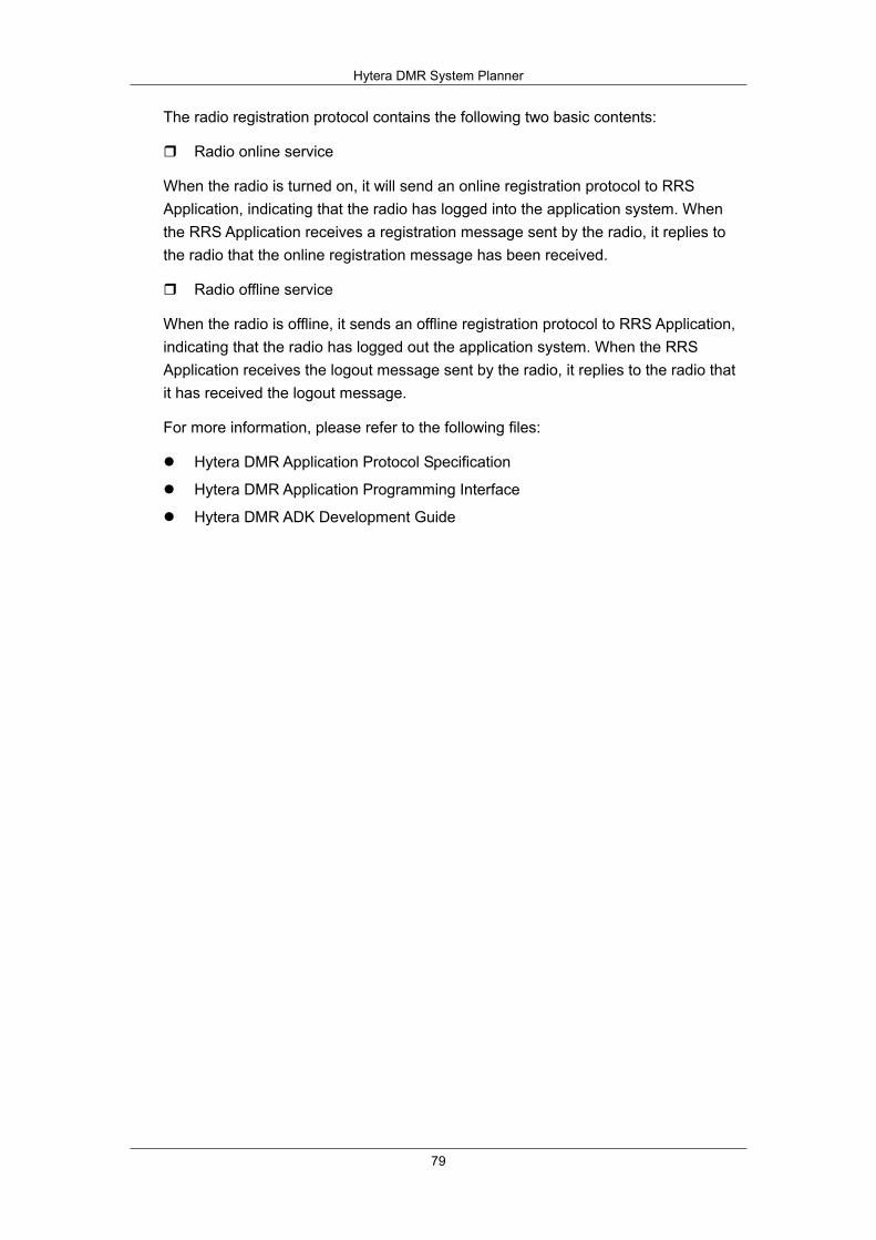
Hytera DMR System Planner
79
The radio registration protocol contains the following two basic contents:
Radio online service
When the radio is turned on, it will send an online registration protocol to RRS Application, indicating that the radio has logged into the application system. When the RRS Application receives a registration message sent by the radio, it replies to the radio that the online registration message has been received.
Radio offline service
When the radio is offline, it sends an offline registration protocol to RRS Application, indicating that the radio has logged out the application system. When the RRS Application receives the logout message sent by the radio, it replies to the radio that it has received the logout message.
For more information, please refer to the following files:
Hytera DMR Application Protocol Specification
Hytera DMR Application Programming Interface
Hytera DMR ADK Development Guide

Hytera DMR System Planner
80
2.11.2 Positioning System(LP)
The topological diagram of Hytera digital location service system is shown in figure below. This system is comprised of three parts: 1) GPS, 2) radio network, and 3) PC.
Figure 2.11.2-1: Hytera Location System Diagram
In the location system, the GPS RX module in the radio receives GPS information (including latitude, longitude, altitude, time, speed), providing basic location data source for the system. Then the received location information is transmitted to the Dispatcher Station in control center over the wireless air interface; finally to PC via the USB cable. PC can communicate with any radio in the wireless radio network. For example, it can request any radio in the system to send its location information.
There are two types of reporting: periodical reporting and single reporting. When the radio is in an emergency, it can send its GPS information to PC, for the dispatcher to arrange rescue according to the location.
The radio communicates with PC via the Hytera Location Protocol (LP); this protocol allows the information to be transmitted in the radio network over the public air interface, and between PC and the Dispatcher Station via the USB cable. The LP
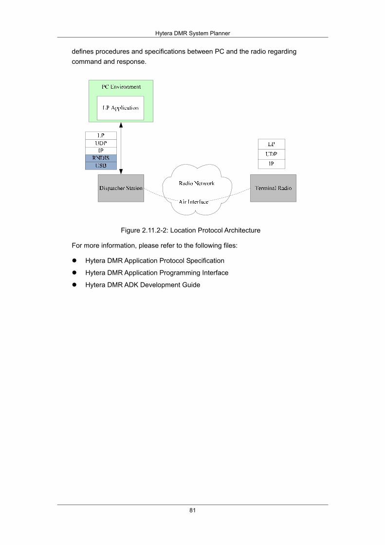
Hytera DMR System Planner
81
defines procedures and specifications between PC and the radio regarding command and response.
Figure 2.11.2-2: Location Protocol Architecture
For more information, please refer to the following files:
Hytera DMR Application Protocol Specification
Hytera DMR Application Programming Interface
Hytera DMR ADK Development Guide

Hytera DMR System Planner
82
2.11.3 Radio Control Service(RCP)
Hytera provides radio control protocol specification and API library based on PC to achieve radio system calling. Hytera digital radio is able to individual calling, group calling and all calling. You can integrate all these calling into user system by ADK and achieve calling from user’s application system.
Figure 2.11.3-1: Radio Control Protocol Architecture
Notes:
In repeater API, HRNP is not needed, because HRNP is usually used in wired communication, such as USB or UART.
As the chart shows, HRNP is a network layer protocol between PC application system and the Dispatcher Station, and a user-defined protocol based on UDP/IP through which PC application system transfers calling order to corresponding distant radio by using the Dispatcher Station as a transient station. The Dispatcher Station will transfer received calling request information to PC application system.
For more details, please refer to below files:
Hytera DMR Application Protocol Specification Hytera DMR Application Programming Interface Hytera DMR ADK Development Guide

Hytera DMR System Planner
83
2.11.4 Text Message Service (TMP)
Hytera Text Message ADK is a simple text message transmission protocol realized in radio system. In radio system, one-to-one text message transmission can be realized, as well as the function of one to multiple. Text Message ADK is an extension based on it enabling user to realize transmitting and receiving text message through ADK interface on PC.
Figure 2.11.4-1: Text message protocol frame
As shown in the figure, the text messages are transmitted by carried in UDP/IP packets through USB cable. In wireless network of radio, the text messages are conveyed via common air interface (CAI).
The following functions can be realized through Hytera Text Message ADK:
PC sends a message to a specific terminal. This task is realized by verifying ID of the terminal. Only those terminals with ID in accordance can receive this message. Those terminals with ID not in accordance will automatically cast off this message.
PC sends a message to all terminals of a group. This task is realized by verifying ID of the terminal. Only those terminals with the same group ID can receive this message.
Terminal sends a message to PC. The terminal sends a message to Dispatcher Station connected with PC. As long as transmission to PC option is set in Dispatcher Station, it will enable PC to receive this message. This message is sent by Dispatcher Station connected with it. At this time, Dispatcher Station plays the function similar as gateway enabling to transmit message in wireless network to PC network.
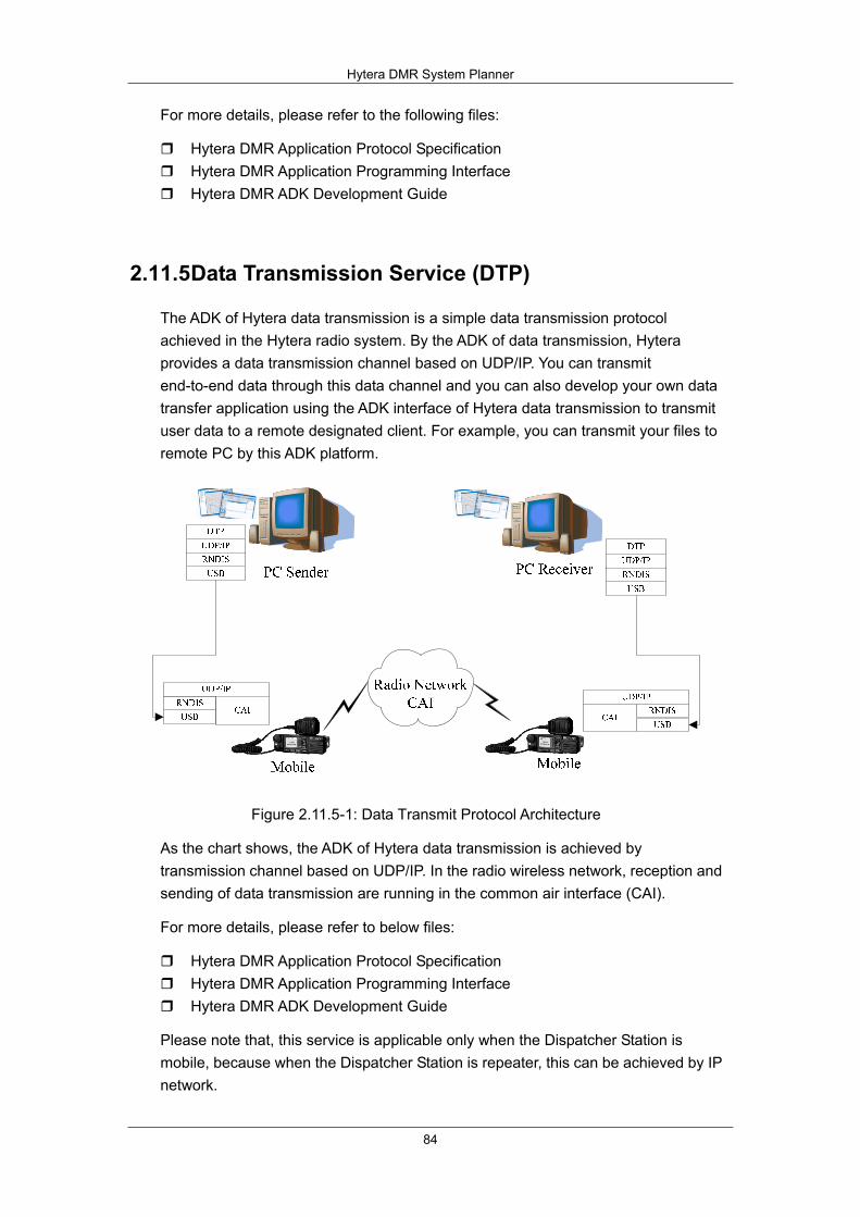
Hytera DMR System Planner
84
For more details, please refer to the following files:
Hytera DMR Application Protocol Specification Hytera DMR Application Programming Interface Hytera DMR ADK Development Guide
2.11.5 Data Transmission Service (DTP)
The ADK of Hytera data transmission is a simple data transmission protocol achieved in the Hytera radio system. By the ADK of data transmission, Hytera provides a data transmission channel based on UDP/IP. You can transmit end-to-end data through this data channel and you can also develop your own data transfer application using the ADK interface of Hytera data transmission to transmit user data to a remote designated client. For example, you can transmit your files to remote PC by this ADK platform.
Figure 2.11.5-1: Data Transmit Protocol Architecture
As the chart shows, the ADK of Hytera data transmission is achieved by transmission channel based on UDP/IP. In the radio wireless network, reception and sending of data transmission are running in the common air interface (CAI).
For more details, please refer to below files:
Hytera DMR Application Protocol Specification Hytera DMR Application Programming Interface Hytera DMR ADK Development Guide
Please note that, this service is applicable only when the Dispatcher Station is mobile, because when the Dispatcher Station is repeater, this can be achieved by IP network.

Hytera DMR System Planner
85
2.11.6 Telemetry Service (TMP)
The ADK of Hytera telemetry provides a telemetry application system based on Hytera radio system on PC. PC application system can monitor Hytera radio input information and also control Hytera radio output information. For example, you can monitor radio GPIO input information and control GPIO output status. When you connect the sensor to the radio GPIO port, the radio is able to monitor sensor changes and send the information to the monitor center by the wireless air interface which enables the operator in the monitor center to real-time monitor the status in the system.
Figure 2.11.6-1: Telemetry protocol framework

Hytera DMR System Planner
86
2.11.7 Real-time Transport Service (RTP)
In radio wireless communication, the radio equipments communicate with each other via air interface. In DMR Systems, the voice is transmitted by encapsulating in DMR frames and encoded in AMBE (or SELP, or some other wireless communication speech coding algorithms). However, as many applications, which is usually deployed in a PC, do not support encoding/decoding with those vocoder, in order to communicate with radios, there must be a voice transport protocol to transport the voice stream and a common known encoding/decoding vocoder between radio equipment and the application.
Figure below illustrate a common topology for communications between radios and PC application. From the figure below, the repeater is responsible for converting voice stream between radio network and UDP/IP network.
Figure 2.11.7-1: Communication between Distinct Networks
Real-time Transport Protocol (RTP) is used to transmit voice stream between the application and Dispatcher Station. RTP provides end-to-end delivery services for data with real-time characteristics, such as interactive audio and video. To satisfy the special requirements of radio wireless communication, RTP header extension is defined to carry particular radio information that allows the application to know more of the call information that is extracted from the DMR protocol.

87
3 Components of DMR System Our DMR communication system mainly consists of the portable radio, mobile radio, repeater and RDAC. These components provide different uses. The users can select them according to their actual requirements.
This chapter describes function and performance of these components, facilitating the users to select proper devices for communication.
Our conventional DMR devices are available in all frequency bands listed below:
U1: 400 - 470MHz
U2: 450 - 520MHz
U3: 350 - 400MHz
U5:
806 - 825MHz (TX only)
851 - 870MHz (TX and RX)
896 - 902MHz (RX only)
935 - 941MHz (TX and RX)
V: 136 - 174MHz
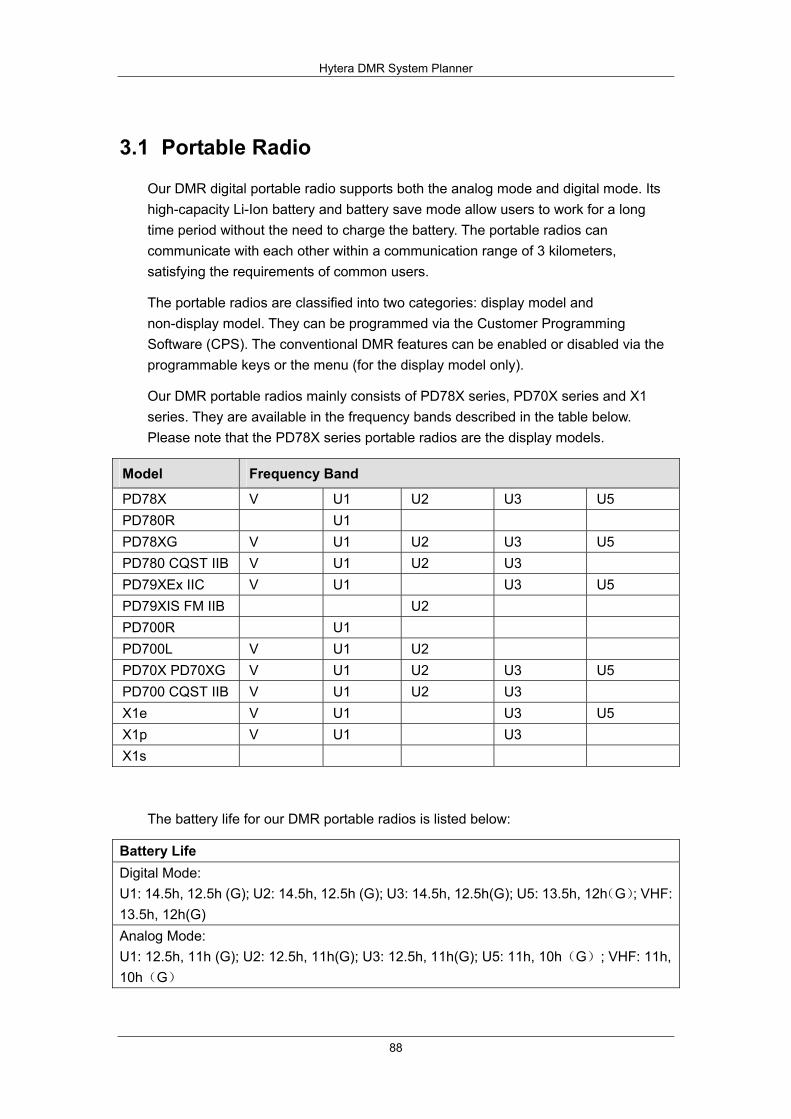
Hytera DMR System Planner
88
3.1 Portable Radio
Our DMR digital portable radio supports both the analog mode and digital mode. Its high-capacity Li-Ion battery and battery save mode allow users to work for a long time period without the need to charge the battery. The portable radios can communicate with each other within a communication range of 3 kilometers, satisfying the requirements of common users.
The portable radios are classified into two categories: display model and non-display model. They can be programmed via the Customer Programming Software (CPS). The conventional DMR features can be enabled or disabled via the programmable keys or the menu (for the display model only).
Our DMR portable radios mainly consists of PD78X series, PD70X series and X1 series. They are available in the frequency bands described in the table below. Please note that the PD78X series portable radios are the display models.
Model Frequency Band
PD78X V U1 U2 U3 U5 PD780R U1 PD78XG V U1 U2 U3 U5 PD780 CQST IIB V U1 U2 U3 PD79XEx IIC V U1 U3 U5 PD79XIS FM IIB U2 PD700R U1 PD700L V U1 U2 PD70X PD70XG V U1 U2 U3 U5 PD700 CQST IIB V U1 U2 U3 X1e V U1 U3 U5 X1p V U1 U3 X1s
The battery life for our DMR portable radios is listed below:
Battery Life Digital Mode: U1: 14.5h, 12.5h (G); U2: 14.5h, 12.5h (G); U3: 14.5h, 12.5h(G); U5: 13.5h, 12h(G); VHF: 13.5h, 12h(G) Analog Mode: U1: 12.5h, 11h (G); U2: 12.5h, 11h(G); U3: 12.5h, 11h(G); U5: 11h, 10h(G); VHF: 11h, 10h(G)
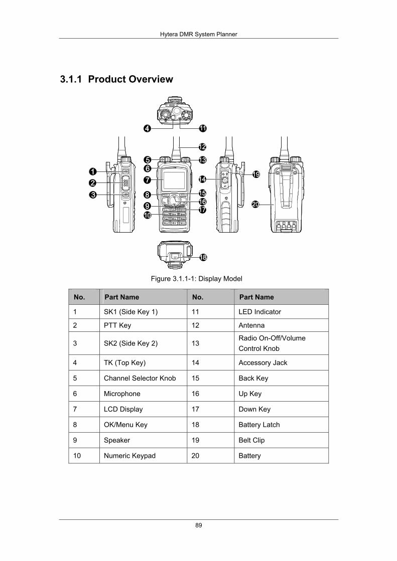
Hytera DMR System Planner
89
3.1.1 Product Overview
Figure 3.1.1-1: Display Model
No. Part Name No. Part Name
1 SK1 (Side Key 1) 11 LED Indicator
2 PTT Key 12 Antenna
3 SK2 (Side Key 2) 13 Radio On-Off/Volume Control Knob
4 TK (Top Key) 14 Accessory Jack
5 Channel Selector Knob 15 Back Key
6 Microphone 16 Up Key
7 LCD Display 17 Down Key
8 OK/Menu Key 18 Battery Latch
9 Speaker 19 Belt Clip
10 Numeric Keypad 20 Battery
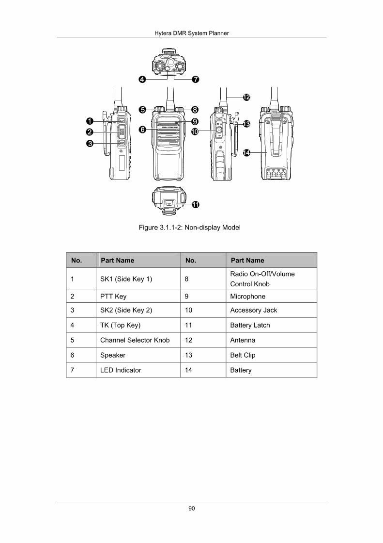
Hytera DMR System Planner
90
Figure 3.1.1-2: Non-display Model
No. Part Name No. Part Name
1 SK1 (Side Key 1) 8 Radio On-Off/Volume Control Knob
2 PTT Key 9 Microphone
3 SK2 (Side Key 2) 10 Accessory Jack
4 TK (Top Key) 11 Battery Latch
5 Channel Selector Knob 12 Antenna
6 Speaker 13 Belt Clip
7 LED Indicator 14 Battery
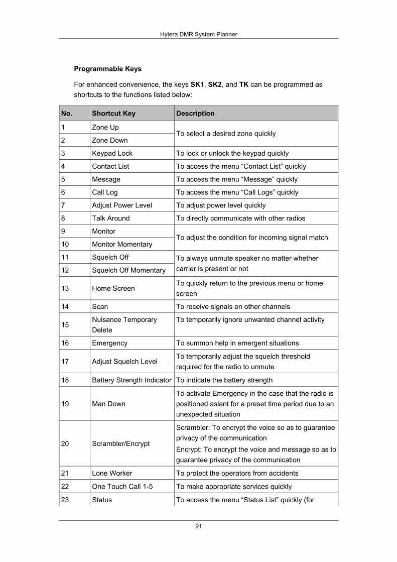
Hytera DMR System Planner
91
Programmable Keys
For enhanced convenience, the keys SK1, SK2, and TK can be programmed as shortcuts to the functions listed below:
No. Shortcut Key Description
1 Zone Up
2 Zone Down To select a desired zone quickly
3 Keypad Lock To lock or unlock the keypad quickly
4 Contact List To access the menu “Contact List” quickly
5 Message To access the menu “Message” quickly
6 Call Log To access the menu “Call Logs” quickly
7 Adjust Power Level To adjust power level quickly
8 Talk Around To directly communicate with other radios
9 Monitor
10 Monitor Momentary To adjust the condition for incoming signal match
11 Squelch Off
12 Squelch Off Momentary
To always unmute speaker no matter whether carrier is present or not
13 Home Screen To quickly return to the previous menu or home screen
14 Scan To receive signals on other channels
15 Nuisance Temporary Delete
To temporarily ignore unwanted channel activity
16 Emergency To summon help in emergent situations
17 Adjust Squelch Level To temporarily adjust the squelch threshold required for the radio to unmute
18 Battery Strength Indicator To indicate the battery strength
19 Man Down To activate Emergency in the case that the radio is positioned aslant for a preset time period due to an unexpected situation
20 Scrambler/Encrypt
Scrambler: To encrypt the voice so as to guarantee privacy of the communication Encrypt: To encrypt the voice and message so as to guarantee privacy of the communication
21 Lone Worker To protect the operators from accidents
22 One Touch Call 1-5 To make appropriate services quickly
23 Status To access the menu “Status List” quickly (for

Hytera DMR System Planner
92
5-Tone)
24 Telemetry To supervise remote devices
25 DTMF Keypad To enter or exit the DTMF keypad mode (In the DTMF Keypad mode, enter a number via the keypad to make a phone call.)
26 Phone List To access the menu “Phone List” quickly
27 Roam To communicate between sites in the IP Multi-site Connect system.
3.1.2 Basic Operations Turning the Radio On/Off
Rotate the Radio On-Off/Volume Control knob clockwise/counter-clockwise until a click is heard to turn the radio on/off
Adjusting the Volume
After turning the radio on, rotate the Radio On-Off/Volume Control knob clockwise to increase the call volume, or counter-clockwise to decrease it.
Selecting a Channel
After turning the radio on, rotate the Channel Selector knob to select a desired channel.
Switching the Channel Mode
Each channel can be programmed as either analog channel or digital channel. If the current zone includes both analog and digital channels, the user can quickly switch between digital and analog through the Channel Selector knob.
Call
To ensure optimal volume of the receiving radio, hold the palm microphone approximately 2.5 to 5 centimeters away from your mouth. You may transmit a Private Call through any of the following methods.
1. Transmitting a call to the preset contact
In the home screen, hold down the PTT key to transmit a Private Call to the Private Call contact preset for the current channel.
2. Transmitting a call through Contact List or Call Logs
3. Through manual input
After a Private Call is received, you may hold down the PTT key within the preset time period to call back. If you do not respond to it, your radio will provide

Hytera DMR System Planner
93
appropriate indications.
Group Call
You may transmit a Group Call through any of the following methods.
1. Transmitting a call to the preset contact
In the home screen, hold down the PTT key to transmit a Group Call to the Group Call contact preset for the current channel.
2. Transmitting a call through Contact List
3. Through manual input
After a Group Call is received, hold down the PTT key within the preset time period to call back.
All Call
Two methods are available for transmitting an All Call: transmitting a call to the preset contact; transmitting a call through Contact List. Please note that you cannot respond to an All Call.
Calls on Analog Channels
To transmit a call, hold down the PTT key and speak into the microphone. To receive, release the PTT key.
Status Indication
The top LED indicator will help you easily identify the current radio status described below:
LED Indication Radio Status
LED flashes green. Powering on
LED glows red. Transmitting
LED glows green. Receiving
LED flashes orange slowly. Scanning
LED flashes orange rapidly. Emergency
LED glows orange. After voice communication ends, you can hold down the PTT key to talk while the LED is glowing orange.
In addition, the radio status can also be identified via the alert tones, which can be customized via the CPS. For the display model, related status indication will also be displayed on the LCD.

Hytera DMR System Planner
94
Menu
Besides key operations, you can also set and operate the radio via the menu. The menu in our radio mainly includes the following items:
Contact List Text Message Call Logs Scan Zone Settings Accessories
For details, please refer to the corresponding owner’s manual.
Numeric Keypad
The display model is designed with a numeric keypad, allowing the user to dial numbers and edit messages. However, the non-display model is not designed with any numeric keypad.
Auxiliary Features
The radio can be programmed via the CPS to provide various auxiliary features such as Radio Check, Remote Monitor, Radio Enable and Radio Disable.
Accessory
A GPS module can be integrated into the antenna of the radio, to provide the positioning service. Via a third-party software, the radio with the GPS module can be positioned. The radio can work with an antenna with or without the GPS module.
GPIO Port
The radio has a 16-pin GPIO interface, which supports various features. This interface can be used to connect the earpiece, to receive calls and to collect the audio signals via the microphone on the earpiece for transmission. In addition, it can be used to connect the PC via a USB cable, to program the radio. The pins of the GPIO interface can be programmed to realize features such as Telemetry and Unmute.
Programmable Features for GPIO Port
For the portable radio, only PIN11 can be programmed with the following features:
No. Programmable Feature Description 1 Telemetry VIO1 This pin is set to Telemetry VIO1.
2 Speaker Open Detect The pin will output an active level when the speaker is detected unmuted.

Hytera DMR System Planner
95
3.2 Mobile Radio
The mobile radio is designed to work in the vehicle and powered by the vehicle’s battery. It works at 13.6V ± 15% with negative end grounded. The product can operate in either analog or digital mode. Compared with the portable radio, the mobile radio extends the communication coverage. The communication distance of this mobile radio in the direct mode can reach to 3-5 kilometers. The mobile radio is equipped with the display. It is highly recommended to program the mobile radio properly before installing in the vehicle.
Currently, the mobile radio (MD78X series) is currently available in the following frequency range.
Model Frequency Band
MD78X V1 U1 U2 U3 U5
MD78XG V1 U1 U2 U3 U5

Hytera DMR System Planner
96
3.2.1 Product Overview Front Panel
3.2.1-1 Front Panel
No. Part Name No. Part Name
1 Volume Control / Channel Selector Knob
2 LED Indicator
3 LCD Display 4 OK/Menu Key
5 Back Key 6 Power On/Off Key
7 Up Key 8 Down Key
9 Speaker 10 Programmable Keys
11 Microphone Jack 12 Microphone Installation Index
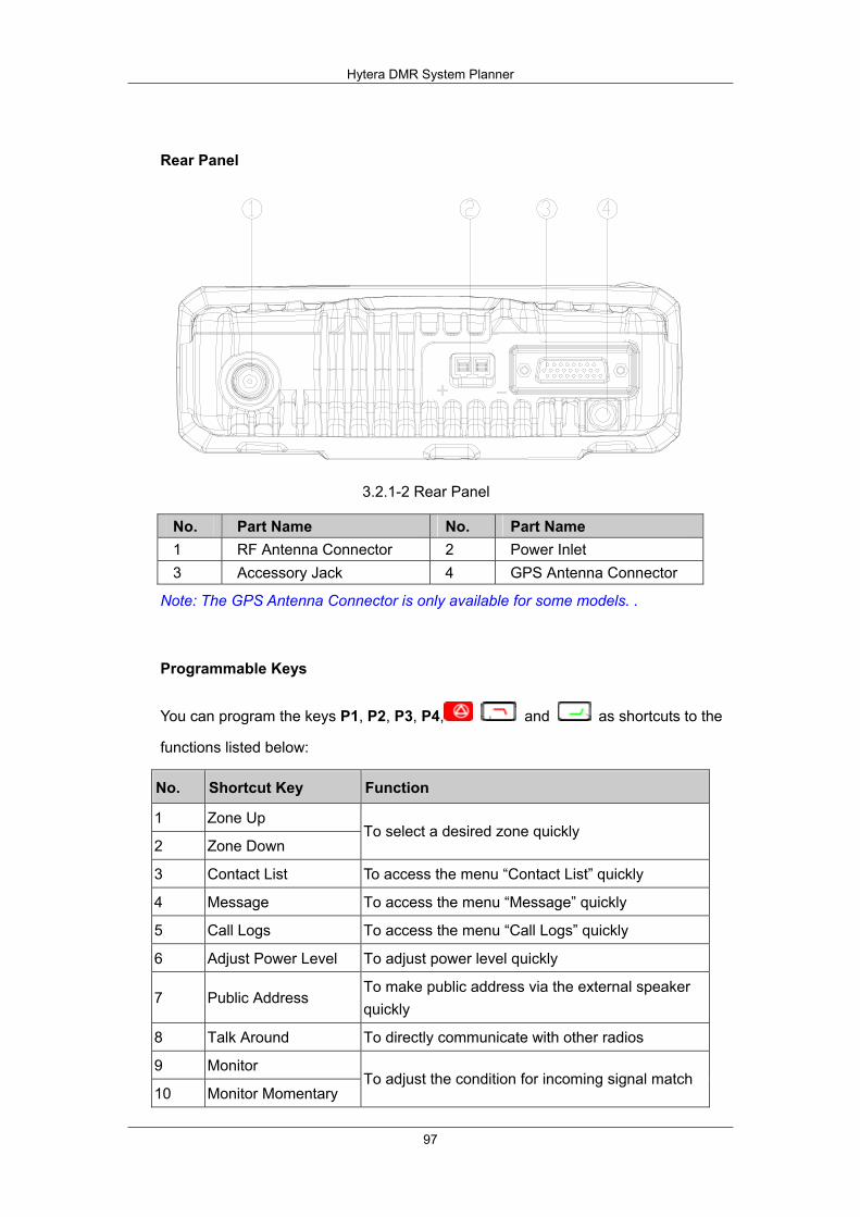
Hytera DMR System Planner
97
Rear Panel
3.2.1-2 Rear Panel
No. Part Name No. Part Name 1 RF Antenna Connector 2 Power Inlet 3 Accessory Jack 4 GPS Antenna Connector
Note: The GPS Antenna Connector is only available for some models. .
Programmable Keys
You can program the keys P1, P2, P3, P4, and as shortcuts to the
functions listed below:
No. Shortcut Key Function
1 Zone Up
2 Zone Down To select a desired zone quickly
3 Contact List To access the menu “Contact List” quickly
4 Message To access the menu “Message” quickly
5 Call Logs To access the menu “Call Logs” quickly
6 Adjust Power Level To adjust power level quickly
7 Public Address To make public address via the external speaker quickly
8 Talk Around To directly communicate with other radios
9 Monitor
10 Monitor Momentary To adjust the condition for incoming signal match
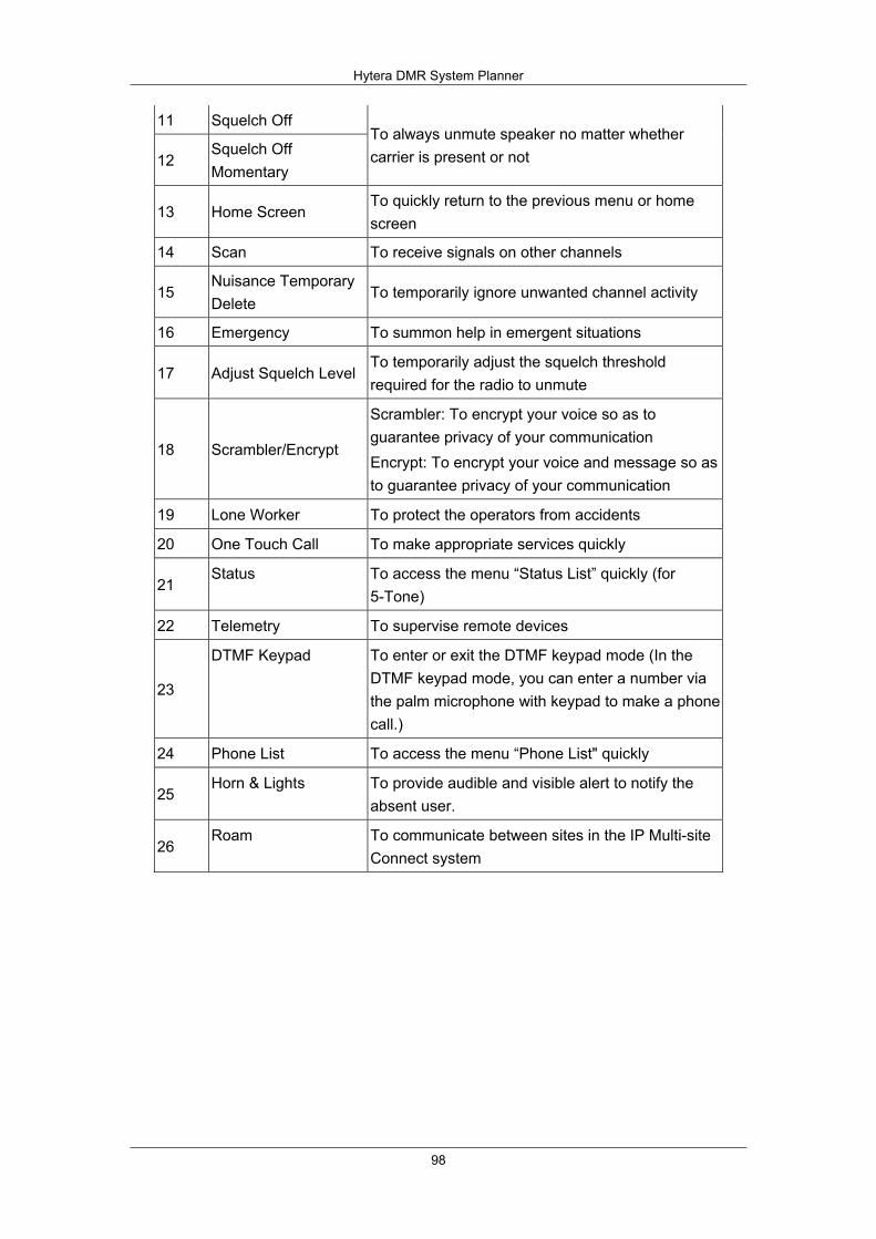
Hytera DMR System Planner
98
11 Squelch Off
12 Squelch Off Momentary
To always unmute speaker no matter whether carrier is present or not
13 Home Screen To quickly return to the previous menu or home screen
14 Scan To receive signals on other channels
15 Nuisance Temporary Delete
To temporarily ignore unwanted channel activity
16 Emergency To summon help in emergent situations
17 Adjust Squelch Level To temporarily adjust the squelch threshold required for the radio to unmute
18 Scrambler/Encrypt
Scrambler: To encrypt your voice so as to guarantee privacy of your communication Encrypt: To encrypt your voice and message so as to guarantee privacy of your communication
19 Lone Worker To protect the operators from accidents
20 One Touch Call To make appropriate services quickly
21 Status To access the menu “Status List” quickly (for
5-Tone)
22 Telemetry To supervise remote devices
23
DTMF Keypad To enter or exit the DTMF keypad mode (In the DTMF keypad mode, you can enter a number via the palm microphone with keypad to make a phone call.)
24 Phone List To access the menu “Phone List" quickly
25 Horn & Lights To provide audible and visible alert to notify the
absent user.
26 Roam To communicate between sites in the IP Multi-site
Connect system

Hytera DMR System Planner
99
3.2.2 Basic Operations Turning the Radio On/Off
To turn the radio on, long press the Power On/Off key until the radio shows start-up screen and sounds an alert tone. Meanwhile, the LED flashes green. To turn the radio off, press the Power On/Off key.
Adjusting the Volume
After the radio is turned on, rotate the Volume Control /Channel Selector knob clockwise to increase the call volume, or counter-clockwise to decrease it.
Selecting a Zone
A zone is a group of channels exhibiting the same property, and is programmed by your dealer. The radio supports up to 64 zones, each with a maximum of 16 channels. Go to the menu “Zone”, and use the Up/Down key to select a zone. You may also quickly switch the zone by pressing the programmed Zone Up or Zone Down key.
Selecting a Channel
Rotate the Volume Control /Channel Selector knob to select a channel. Alias of the current channel will appear in the home screen.
Switching the Channel Mode
Each channel can be programmed as either analog channel or digital channel. If the current zone includes both analog and digital channels, you may quickly switch between digital and analog channels through the Volume Control /Channel Selector knob.
Call
Private Call
Transmitting a Private Call
You may transmit a private call through any of the following methods.
1. Transmitting a call to the preset contact

Hytera DMR System Planner
100
2. Transmitting a call through Contact List or Call Logs
3. Transmitting a call through Manual Dial
Receiving and Responding to a Private Call
After a Private Call is received, you may hold down the PTT key within the preset time period to call back. If you do not respond to it, your radio will provide appropriate indications.
Group Call
Transmitting a Group Call
You may transmit a group call through any of the following methods.
1. Transmitting a call to the preset contact
2. Transmitting a call through Contact List
3. Transmitting a call through Manual Dial
Receiving and Responding to a Group Call
After a Group Call is received, you may hold down the PTT key within the preset time period to call back. If you do not respond to it, the radio will display the missed call icon. The indication information is the same as that for the Private Call.
All Call
Two methods are available for transmitting an All Call: transmitting a call to the preset contact; transmitting a call through Contact List.
Receiving an All Call
When an All Call is received, your radio will display an indication icon.
Calls on Analog Channels
To transmit a call, hold down the PTT key and speak into the microphone. To receive, release the PTT key.
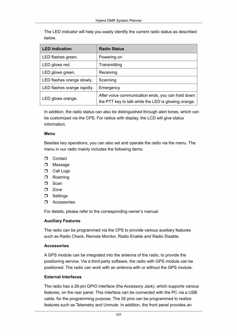
Hytera DMR System Planner
101
The LED indicator will help you easily identify the current radio status as described below.
LED Indication Radio Status
LED flashes green. Powering on
LED glows red. Transmitting
LED glows green. Receiving
LED flashes orange slowly. Scanning
LED flashes orange rapidly. Emergency
LED glows orange. After voice communication ends, you can hold down the PTT key to talk while the LED is glowing orange.
In addition, the radio status can also be distinguished through alert tones, which can be customized via the CPS. For radios with display, the LCD will give status information.
Menu
Besides key operations, you can also set and operate the radio via the menu. The menu in our radio mainly includes the following items:
Contact Message Call Logs Roaming Scan Zone Settings Accessories
For details, please refer to the corresponding owner’s manual.
Auxiliary Features
The radio can be programmed via the CPS to provide various auxiliary features such as Radio Check, Remote Monitor, Radio Enable and Radio Disable.
Accessories
A GPS module can be integrated into the antenna of the radio, to provide the positioning service. Via a third-party software, the radio with GPS module can be positioned. The radio can work with an antenna with or without the GPS module.
External Interfaces
The radio has a 26-pin GPIO interface (the Accessory Jack), which supports various features, on the rear panel. This interface can be connected with the PC via a USB cable, for the programming purpose. The 26 pins can be programmed to realize features such as Telemetry and Unmute. In addition, the front panel provides an
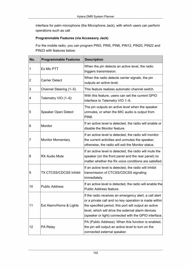
Hytera DMR System Planner
102
interface for palm microphone (the Microphone Jack), with which users can perform operations such as call.
Programmable Features (via Accessory Jack)
For the mobile radio, you can program PIN3, PIN5, PIN6, PIN12, PIN20, PIN22 and PIN23 with features below:
No. Programmable Features Description
1 Ex Mic PTT When the pin detects an active level, the radio triggers transmission.
2 Carrier Detect When the radio detects carrier signals, the pin outputs an active level.
3 Channel Steering (1–5) This feature realizes automatic channel switch.
4 Telemetry VIO (1–6) With this feature, users can set the current GPIO interface to Telemetry VIO 1–6.
5 Speaker Open Detect The pin outputs an active level when the speaker unmutes, or when the MIC audio is output from PIN8.
6 Monitor If an active level is detected, the radio will enable or disable the Monitor feature.
7 Monitor Momentary If an active level is detected, the radio will monitor the current activities and unmutes the speaker; otherwise, the radio will exit the Monitor status.
8 RX Audio Mute If an active level is detected, the radio will mute the speaker (on the front panel and the rear panel) no matter whether the Rx voice conditions are satisfied.
9 TX CTCSS/CDCSS Inhibit If an active level is detected, the radio will inhibit transmission of CTCSS/CDCSS signaling immediately.
10 Public Address If an active level is detected, the radio will enable the Public Address feature.
11 Ext Alarm/Horns & Lights
If the radio receives an emergency alert, a call alert or a private call and no key operation is made within the specified period, this port will output an active level, which will drive the external alarm devices (speaker or light) connected with the GPIO interface.
12 PA Relay PA (Public Address): When this function is enabled, the pin will output an active level to turn on the connected external speaker.
Hytera DMR System Planner
103
3.3 Repeater
The repeater is used to expand the communication range by reinforcing and transmitting the signal sent by the terminals. With repeater, the communication range expands to 20 kilometers. The conventional repeater is supplied with AC, and the packable repeater is supplied by battery.
The main functions of a repeater are to retransmit the signal sent by terminals and to enhance error correcting.
When communicate with terminals, the communication range is small as the TX power is low and the signal will be weakened by distance and interference. The repeater can enable the signal to reach a further distance and the audio to perform well by reinforce the signal and correct the interfered signal. The digital repeater can support IP network, which can expand the communications range at a large scale. With such kind of network, multiple repeaters can communicate with each other, which enables the terminals of each repeater can communicate with each other. Such network mode can be used in local communications of a scale.
As the repeater first receives then retransmits signal, the TX and RX frequency should be different to avoid self-interference, so are the frequencies of terminal. DMR digital repeater can work in analog mode.
Hytera digital repeater can be configured via CPS; what’s more, to keep maintenance, it can be remotely configured via the RDAC. With this feature, the repeater used in remote areas, like forests or mountains can be easily monitored and configured, which enhances the work effectiveness.
At present, the available repeater is the RD98X series. It is applied in following frequency ranges:
Model Applicability
RD98X V1 U1 U2 U3
RD98XM U1 U3
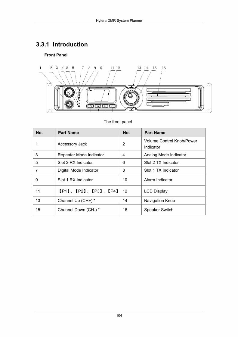
Hytera DMR System Planner
104
3.3.1 Introduction Front Panel
The front panel
No. Part Name No. Part Name
1 Accessory Jack 2 Volume Control Knob/Power Indicator
3 Repeater Mode Indicator 4 Analog Mode Indicator
5 Slot 2 RX Indicator 6 Slot 2 TX Indicator
7 Digital Mode Indicator 8 Slot 1 TX Indicator
9 Slot 1 RX Indicator 10 Alarm Indicator
11 【P1】, 【P2】, 【P3】, 【P4】 12 LCD Display
13 Channel Up (CH+) * 14 Navigation Knob
15 Channel Down (CH-) * 16 Speaker Switch

Hytera DMR System Planner
105
Rear Panel
The rear panel
No. Part Name No. Part Name
1 TX Antenna Connector 2 Optional Interface 1
3 RX/Duplex Antenna Connector 4 Optional Interface 2
5 Monitor/Tuning Interface 6 Accessory Jack
7 DC Power Inlet 8 Ethernet Interface
9 Ground Screw
Programmable Keys
The P1, P2, P3, P4 can be programmed as shortcut to the following functions:
No. Shortcut Key Function
1 Adjust Power Level To adjust TX power level quickly
2 Repeater/Base mode To switch the work mode of the repeater
3 Smart Digital-Analog Switch To switch the communications mode
4 Adjust Squelch Level To temporarily adjust the squelch threshold required for the radio to unmute
5 Squelch Close Temporarily To temporarily turn off the squelch function
6 Squelch Off To turn off the squelch function
7 Monitor Momentary To enter the monitoring mode by pressing the key; while releasing the key, it would exit the mode
8 Monitor Button To enter the monitoring mode by pressing the key; while pressing the key again, it would exit the mode

Hytera DMR System Planner
106
3.3.2 Basic Operations Powering On/Off
Connect the repeater to a DC source to turn the repeater on. During power-up process, the Power Indicator glows green and the repeater shows the power-on screen.
To turn the repeater off, disconnect it from the DC source.
Adjusting the Volume
In analog mode: rotate the Volume Control knob clockwise to increase the volume or counter-clockwise to decrease the volume.
In digital mode: the speaker is muted, so this knob does not work.
Adjusting the Power Level
The TX power can be configured via CPS by the dealer. High power can expand repeater coverage, enabling you to communicate with terminals in the distance. There are two levels available: High (indicated by H) and Low (indicated by L).
Backlight
Activating the backlight can illuminate the LCD and all the front panel keys, which facilitates operation. The customers can set the work status of the backlight via CPS. You can select one of the following statuses.
Timed: operation on any key or knob can illuminate the backlight. If there is no operation on the product within the specified time, the backlight will go out automatically.
Never turn off: the backlight remains activated all the time.
Locking/Unlocking
You can request your dealer to lock the knob and all keys on the front panel to prevent accidental operations. To unlock, the repeater must be re-programmed by your dealer.
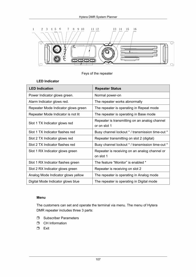
Hytera DMR System Planner
107
Feys of the repeater
LED Indicator
LED Indication Repeater Status
Power Indicator glows green. Normal power-on
Alarm Indicator glows red. The repeater works abnormally
Repeater Mode Indicator glows green The repeater is operating in Repeat mode
Repeater Mode Indicator is not lit The repeater is operating in Base mode
Slot 1 TX Indicator glows red Repeater is transmitting on an analog channel or on slot 1
Slot 1 TX Indicator flashes red Busy channel lockout * / transmission time-out *
Slot 2 TX Indicator glows red Repeater transmitting on slot 2 (digital)
Slot 2 TX Indicator flashes red Busy channel lockout * / transmission time-out *
Slot 1 RX Indicator glows green Repeater is receiving on an analog channel or on slot 1
Slot 1 RX Indicator flashes green The feature “Monitor” is enabled *
Slot 2 RX Indicator glows green Repeater is receiving on slot 2
Analog Mode Indicator glows yellow The repeater is operating in Analog mode
Digital Mode Indicator glows blue The repeater is operating in Digital mode
Menu
The customers can set and operate the terminal via menu. The menu of Hytera DMR repeater includes three 3 parts:
Subscriber Parameters CH Information Exit

Hytera DMR System Planner
108
External accessory jack
In the rear part, the GPIO port uses a 26-pin board-to-board connector to connect with external device to get multiple features. The customers can program every pin port of the GPIO port. Apart from the 26-pin GPIO, a general network interface enables the customers to connect with the network to organize IP network.
Operation mode of the repeater
There are three operation modes in IP networking: Single Site, IP Multi-site Master, IP Multi-site Slave. For you need, you can select one:
Single Site: The repeater is a local one which does not support IP network. IP Multi-site Master: The repeater is set as the master of IP network system and
can communicate with other repeaters in the IP network system. IP Multi-site Slave: The repeater is set as member of the IP network system and
can communicate with other members and the master of the IP network system.
CWID (Continuous Wave Identification)
In Northern America, to reinforce supervision on wireless apparatus, the working repeater must send an ID code (CWID code) regularly to the control center.
CWID code is transmitted in the form of Morse code, which is composed of letters, numerals and a small set of punctuations. It can transmit at most 44 characters. Numerals: 0-9; Letters: A-Z; Punctuations: Space,? / “ ‘ : ! – ( ) @
Programmable features for GPIO port
The GPIO port supports multiple programmable features, and you can configure the port to get your feature. The following table shows you the programmable features:
No. Shortcut Key Function
1 Ex Mic PTT When an active level is detected, the port will be an input port and the transmission will be triggered.
2 Carrier detection When the carrier signal is detected, the port will output an active level.
3 CTCSS detection When the CTCSS signal is detected, the port will output an active level.
4 The repeat function disabled
When an active level is detected, the repeater will deactivate the path of retransmitting until the level disappears.
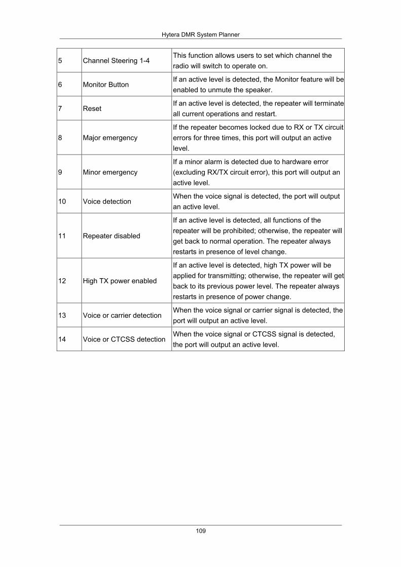
Hytera DMR System Planner
109
5 Channel Steering 1-4 This function allows users to set which channel the radio will switch to operate on.
6 Monitor Button If an active level is detected, the Monitor feature will be enabled to unmute the speaker.
7 Reset If an active level is detected, the repeater will terminate all current operations and restart.
8 Major emergency If the repeater becomes locked due to RX or TX circuit errors for three times, this port will output an active level.
9 Minor emergency If a minor alarm is detected due to hardware error (excluding RX/TX circuit error), this port will output an active level.
10 Voice detection When the voice signal is detected, the port will output an active level.
11 Repeater disabled
If an active level is detected, all functions of the repeater will be prohibited; otherwise, the repeater will get back to normal operation. The repeater always restarts in presence of level change.
12 High TX power enabled
If an active level is detected, high TX power will be applied for transmitting; otherwise, the repeater will get back to its previous power level. The repeater always restarts in presence of power change.
13 Voice or carrier detection When the voice signal or carrier signal is detected, the port will output an active level.
14 Voice or CTCSS detection When the voice signal or CTCSS signal is detected, the port will output an active level.

Hytera DMR System Planner
110
3.4 RDAC (Repeater Diagnostics and Control)
RADC is designed to facilitate the use of the new generation digital repeater. This software can be installed and operated on the following systems: Windows XP, Windows vista and Window 7 series 32-bit.
RDAC is designed to by Hytera remotely diagnose and control the repeater. With RDAC, the repeater can work in normal state longer, and when any problem occurs, immediate maintenance will be carried out. It does good to cost effectiveness and the use of repeater in retransmitting communications.
RDAC plays a great role in the remote diagnosing and control. In terms of diagnosing, control as well as setting and log. It can diagnose the voltage, temperature, fan, TX power, RX power, VSWR, RX PLL state and TX PLL state. It can remotely control the repeater, forbid re-transmitting, disable the repeater and enable the repeater. It can remotely configure various parameters of the repeater. It can automatically produce the alarm report and diagnosing log to facilitate the user to know the accidences.
Network support
It surpasses the software of a kind. It enables multiple masters (up to 16), every of which can support up to 30 slaves to work in the IP network. After the RADC connects with the master, it can get the IP address of the slaves. Thus, it can effectively and efficiently diagnose and control the master and the slaves at the same time.
Access Management
Access management has two types: Local Access Management and Multi-site Access Management. Such kind of management can optimize and better utilize the retransmission function,
Customization
Multiple versions of Hytera RDAC software are available. You can choose one for your need.

Hytera DMR System Planner
111
3.4.1 Diagnose
RDAC can remotely supervise the operation state of the repeater. Once accidental event occurs, it will take measure immediately to ensure the repeater can work longer.
Items would be diagnosed:
PSU Voltage
Monitor the voltage and alarm voltage in real time.
PA Temperature
Monitor the temperature in real time. Once the temperature is higher than the specified value, an alarm will be given.
Fan State
Monitor the state of the fan in real time. Once any abnormal situation occurs, an alarm will be given.
TX Power
Monitor the TX power in real time.
TX REF Power
Monitor the TX REF Power in real time.
VSWR
Monitor the value of VSWR in real time. Once any abnormal situation occurs, an alarm will be given.
RX PLL State
Monitor the voltage value and the state of the RX PLL circuit. Once abnormal situation occurs, an alarm will be given.
TX PLL State
Monitor the voltage value and the state of the TX PLL circuit. Once abnormal situation occurs, an alarm will be given.
Hytera DMR System Planner
112
3.4.2 Control
RDAC can control the operation mode and state of the repeater.
Restart the repeater Input the modified parameters. The following parameters can be modified.
Current channel
The TX power
The state of repeater: to enable or disable the repeater
Knockdown: to enable or disable the retransmitting function.
Reload the current parameters.
Get the current parameters of the repeater to know its operation state.
View RSSI Data
You can know the RSSI from RDAC. By assessing the RSSI, the RADC will take respective measure to improve telecommunications performance. RADC can monitor the RSSI in real time.
RDAC Log: RDAC can automatically record the diagnosing and control. The RDAC can operate on the following items:
View RDAC Log
View diagnosing record
Delete diagnosing record
The alarm report records the alarm information and is available to be viewed.
View alarm report
View Alarm Log
Delete the alarm report: you can delete the alarm record one by one or delete all at a time.
Hytera DMR System Planner
113
3.4.3 Repeater Configuration
To get normal communications, you can configure following parameters via RDAC to set the repeater in good performance.
Basic setting:
Powering on
Designated power-up zone/channel
Designate power-on channel
Designate power-on zone
Audio Priority
You can select one of the following priorities:
FCFS
Path Priority
Local PTT Priority
Microphone
Set the value of the internal microphone gain.
Set the value of the external microphone gain.
IP Multi-site Connect
Set the jitter buffer length
Set beacon duration
Set beacon interval
Set repeat request priority
Set access manager
Set start ID/end ID
Set CDCSS encoding and decoding frequency value
Hytera DMR System Planner
114
Digital channel setting:
Color Code
Configure the channel color code (range: 1-15).
IP Multi-site Connect
Configure whether to retransmit the signal via IP network and specify a time slot.
RX Frequency
Configure the RX frequency.
TX Frequency
Configure the TX frequency.
Analog channel setting:
Channel Spacing
Configure the bandwidth of the TX frequency and RX frequency.
Carrier Squelch Level
For better communications, you can set the squelch level of the repeater.
Multi CTC/CDC codec
Set whether the Multi CTC/CD table is applied during decoding.
Pre-emphasis
Set whether the audio would be pre-emphasized.
Scrambler
Set whether the signal will be encrypted.
Flat Audio
Set the way of the output of the audio signal from the accessory pin.
Receiving
Set RX frequency
Set CTCSS/CDCSS type.
Set CTCSS.
Set CDCSS

Hytera DMR System Planner
115
Transmitting
Set the TX frequency.
Set TX CTCSS/CDCSS type.
Set CTCSS.
Set CDCSS code
Mixed channel setting:
Channel Spacing
Configure the bandwidth of the TX frequency and RX frequency.
Carrier Squelch Level
For better communications, you can set the squelch level of the repeater.
Color Code
Set whether the CTCSS/CDCSS table is applied during decoding.
Type of PTT TX Channel
Set the channel for transmitting audio.
Pre-emphasis
Set whether the audio would be pre-emphasized.
Scrambler
Set whether the signal will be encrypted.
Flat Audio
Set the way of the output of the audio signal from the accessory pin.
Receiving
Set RX frequency
Set CTCSS/CDCSS type.
Set CTCSS.
Set CDCSS code
Transmitting
Set the TX frequency.
Set TX CTCSS/CDCSS type.
Set CTCSS.
Hytera DMR System Planner
116
Set CDCSS code
Service setting:
Group call hang time
Set the duration the radio stays at in_call status after a group call transmission. You can call back the group directly without contact list selection.
Private Call Hang Time
Set the duration the radio stays at in_call status after a private call transmission. You can call back the group directly with no ACK and is not necessary to select from contact list.
Emergency Call Hang Time
Set the duration the repeater reserves the channel after the end of an emergency call transmission.
Subscriber Inactivity Timer
Set the time period to detect signal when there is no transmitting. When the time expires, the repeater will enter IDLE status and wait for the next activation.
Multisite Access Management
Set Multisite Access Management
Set start ID/end ID
Set the type of call.
Access Manager
Set start ID/end ID
117
4 DMR System Topologies This section is intended to introduce the working mode and various application solutions.
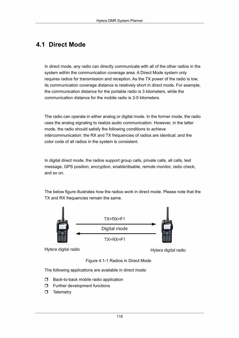
Hytera DMR System Planner
118
4.1 Direct Mode
In direct mode, any radio can directly communicate with all of the other radios in the system within the communication coverage area. A Direct Mode system only requires radios for transmission and reception. As the TX power of the radio is low, its communication coverage distance is relatively short in direct mode. For example, the communication distance for the portable radio is 3 kilometers, while the communication distance for the mobile radio is 3-5 kilometers.
The radio can operate in either analog or digital mode. In the former mode, the radio uses the analog signaling to realize audio communication. However, in the latter mode, the radio should satisfy the following conditions to achieve intercommunication: the RX and TX frequencies of radios are identical; and the color code of all radios in the system is consistent.
In digital direct mode, the radios support group calls, private calls, all calls, text message, GPS position, encryption, enable/disable, remote monitor, radio check, and so on.
The below figure illustrates how the radios work in direct mode. Please note that the TX and RX frequencies remain the same.
Figure 4.1-1 Radios in Direct Mode
The following applications are available in direct mode:
Back-to-back mobile radio application Further development functions Telemetry

Hytera DMR System Planner
119
4.1.1 Back-to-Back Mobile Radio Application in Direct
Mode
The “back-to-back” is a system solution on accessory pins. It is used to achieve cross-band communication among analog and digital radios.
The back-to-back function realizes communication between analog and digital mobile radios. It works as below:
1. When the radio R1 transmits, the radio R2, R3 and the mobile radio 1 will receive the signals from R1 simultaneously.
2. During retransmitting, the mobile radio 1 will output the audio signals to the mobile radio 2 via accessory pin and activate its Mic PTT, triggering the mobile radio 2 to transmit. This operation is not subject to the working mode and frequency of two mobile radios.
3. The radios R4, R5 and R6 receive the same audio signals from mobile radio 2, and this signal is the same as that one from the mobile radio 1. In this way, R1 can communicate with R2, R3, R4, R5 and R6 successfully.
4. The mobile radio 2 can also output the audio signal to mobile radio 1 via accessory pin, enabling all radios within the coverage of two mobile radios to communicate with each other.
Figure 4.1.1-1 Back-to-Back Mobile Radio in Direct Mode

Hytera DMR System Planner
120
4.1.1.1 Back-to-Back Mobile Radio Connection
The mobile radios can be connected in a back-to-back manner as below (Figure 2.15-2):
Figure 4.1.1-2 Back-to-Back Mobile Radio Connection
1) Ground wire
Connect Pin2 of mobile radio1 to that of mobile radio 2.
2) Activation of mobile radio transmission
Connect Pin3 of mobile radio 1 to Pin16 of mobile radio 2.
Connect the Pin16 of mobile radio 1 to the Pin3 of mobile radio 2.
3) Audio signal output
Connect the Pin8 of mobile radio 1 to the Pin7 of mobile radio 2.
Connect the Pin7 of mobile radio 1 to the Pin8 of mobile radio 2.
Note: Pin3 is programmable and can be replaced by Pin12, Pin20, Pin22 or Pin23. All other pins must be connected.
In direct mode, the digital radio can not communicate with the analog radios, even if the mobile radio can operate in either analog or digital mode. However, many customers currently use the analog radio, which can not communicate with the digital radios. In this case, you can adopt the back-to-back mobile radio application to solve this problem. It supports analog-to-digital conversion, enabling the digital radio to communicate with the analog radio.
This back-to-back solution is based on accessory pins of the mobile radio. On the one hand, the analog mobile radio can transmit the received audio data to the digital mobile radio via the accessory pins, and then trigger the PTT of this digital radio to

Hytera DMR System Planner
121
encode the received audio data and transmit it as the digital signal. Thus the digital radios within the communication coverage area can receive the call. On the other hand, the analog mobile radio can transmit the received analog audio data to other mobile radios at other frequencies via the accessory pins, and then trigger the PTT of the analog mobile radio to transmit this analog signal. Thus, all analog radios within the communication coverage area can receive this call. When the analog radio transmits the audio signal, the analog mobile radio will receive this signal, transmit it to the digital mobile radio, and activate the PTT for transmission. In this case, the signal the digital mobile radio transmits is the digital signal, to achieve analog-to-digital conversion.
See the figure below.
Figure 4.1.1-3 Analog-to-digital Conversion 1
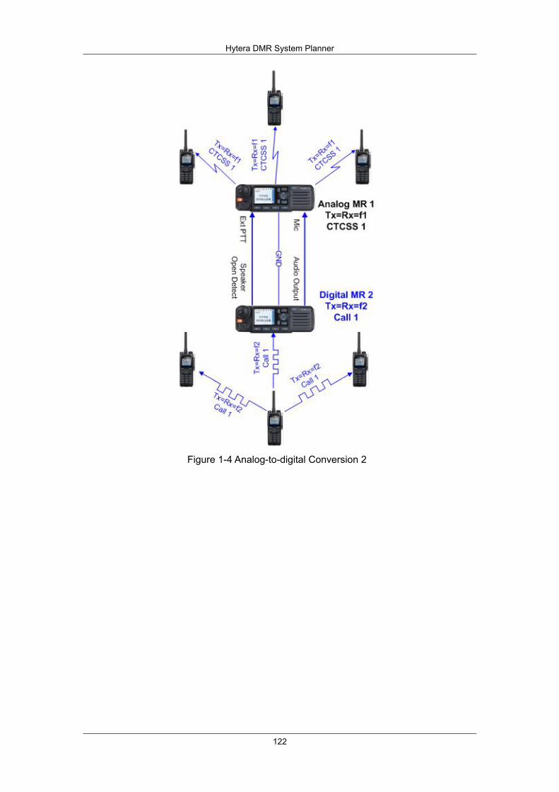
Hytera DMR System Planner
122
Figure 1-4 Analog-to-digital Conversion 2

Hytera DMR System Planner
123
4.1.2 Further Development Functions in Direct Mode
The mobile radio has available interface for further development in direct mode. Currently, the data services developed by the third party include GPS, text message, telemetry, radio control, data transmission and radio registration. The mobile radio can communicate with the computer via the USB port, and exchange data with other radios via the air interface. See the figure below.
Figure 2-1 Further Development Feature in Direct Mode
You can use the third-party application to communicate with the radio, to realize voice call, text message, telemetry, and GPS services.
To be specific, you can connect the mobile radio to the computer, and set the corresponding parameters, to realize data communication between the mobile radio and computer. Please note that the data server protocol for the mobile radio is based on UDP/IP protocol. The third-party application can communicate with the radio via the mobile radio. The end user might be the portable radio or mobile radio, while the mobile radio acts as the dispatch station to connect the computer and terminal.

Hytera DMR System Planner
124
4.1.3 Telemetry
In direct mode, Telemetry is a function, which allows you to stay in control of your device remotely. To send the telemetry command properly, it shall satisfy these conditions: both TX and RX frequencies are consistent, the color codes are identical, and the radio is programmed properly. . The third party is responsible for developing the interface of the external device for using telemetry feature. Once the potential difference of GPIO Pin port in the connected radio changes, the telemetry command will be triggered. Or, if the potential difference of GPIO Pin port in the radio changes, the status of the external equipment will change as well. Telemetry is used to achieve the following functions.
Querying the status of remote telemetry equipment
Querying the status of remote telemetry device
Source radio:
1) Send a query command to the target radio to check the GPIO status of remote terminal, so as to get the status of telemetry equipment. Note that the query command shall be sent via private call.
2) Receive the query result and get the status of telemetry device.
Target radio:
1) Receive the query command.
2) Retrieve the status information of telemetry device.
3) Send GPIO status to the source radio sending the query command.
You can also use this feature to check the status of your desired device remotely such as the door.

Hytera DMR System Planner
125
2) Controlling a remote equipment
Controlling a remote device
Source radio:
1) Send the control command to a radio or a group of radios. This command can cause the specified GPIO Pin to output active/inactive voltage, to toggle the voltage or to output pulse, enabling you to control the remote device.
2) Receive the control response from target radio to get the control result.
Target radio:
1) Receive the control command.
2) Perform the requested command on the telemetry device.
3) Send operation result to the source radio. However, no reply will be given if the control command is sent via group call.
This feature allows you to control a device remotely such as opening an automatic door remotely.
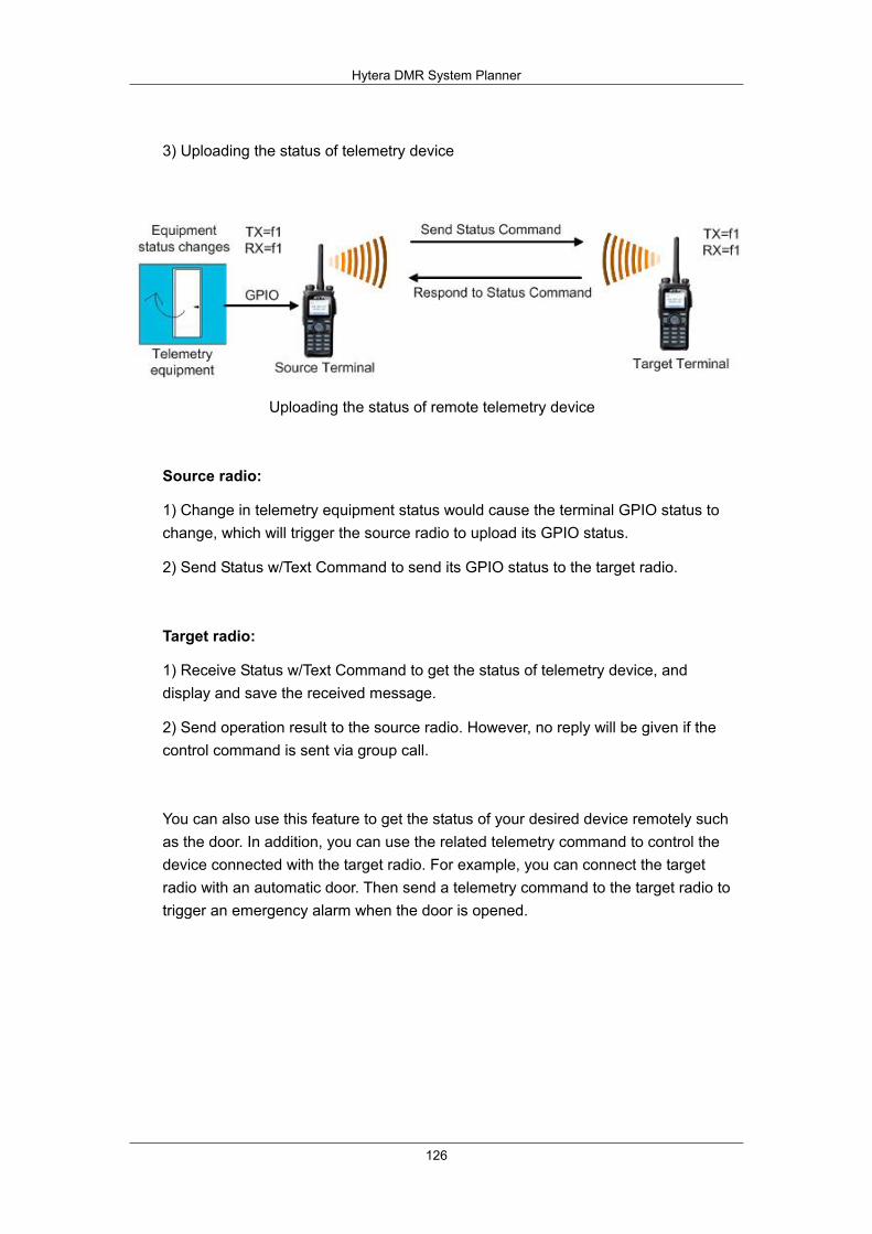
Hytera DMR System Planner
126
3) Uploading the status of telemetry device
Uploading the status of remote telemetry device
Source radio:
1) Change in telemetry equipment status would cause the terminal GPIO status to change, which will trigger the source radio to upload its GPIO status.
2) Send Status w/Text Command to send its GPIO status to the target radio.
Target radio:
1) Receive Status w/Text Command to get the status of telemetry device, and display and save the received message.
2) Send operation result to the source radio. However, no reply will be given if the control command is sent via group call.
You can also use this feature to get the status of your desired device remotely such as the door. In addition, you can use the related telemetry command to control the device connected with the target radio. For example, you can connect the target radio with an automatic door. Then send a telemetry command to the target radio to trigger an emergency alarm when the door is opened.
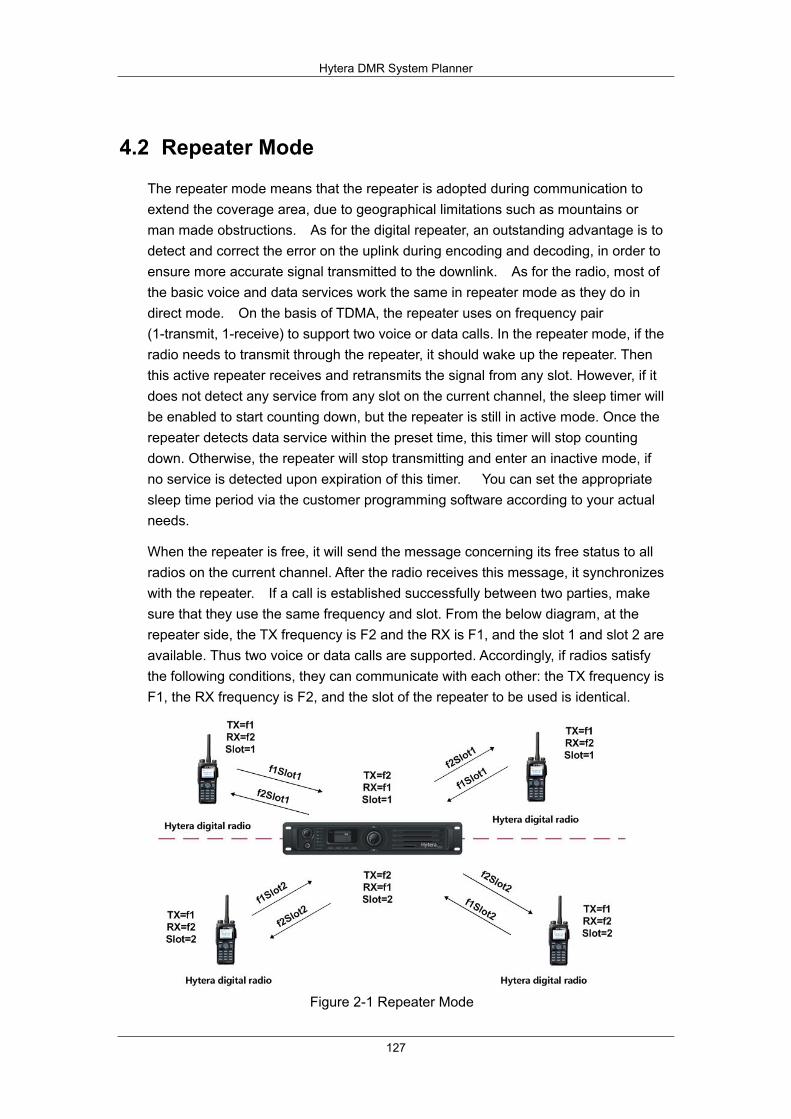
Hytera DMR System Planner
127
4.2 Repeater Mode
The repeater mode means that the repeater is adopted during communication to extend the coverage area, due to geographical limitations such as mountains or man made obstructions. As for the digital repeater, an outstanding advantage is to detect and correct the error on the uplink during encoding and decoding, in order to ensure more accurate signal transmitted to the downlink. As for the radio, most of the basic voice and data services work the same in repeater mode as they do in direct mode. On the basis of TDMA, the repeater uses on frequency pair (1-transmit, 1-receive) to support two voice or data calls. In the repeater mode, if the radio needs to transmit through the repeater, it should wake up the repeater. Then this active repeater receives and retransmits the signal from any slot. However, if it does not detect any service from any slot on the current channel, the sleep timer will be enabled to start counting down, but the repeater is still in active mode. Once the repeater detects data service within the preset time, this timer will stop counting down. Otherwise, the repeater will stop transmitting and enter an inactive mode, if no service is detected upon expiration of this timer. You can set the appropriate sleep time period via the customer programming software according to your actual needs.
When the repeater is free, it will send the message concerning its free status to all radios on the current channel. After the radio receives this message, it synchronizes with the repeater. If a call is established successfully between two parties, make sure that they use the same frequency and slot. From the below diagram, at the repeater side, the TX frequency is F2 and the RX is F1, and the slot 1 and slot 2 are available. Thus two voice or data calls are supported. Accordingly, if radios satisfy the following conditions, they can communicate with each other: the TX frequency is F1, the RX frequency is F2, and the slot of the repeater to be used is identical.
Figure 2-1 Repeater Mode
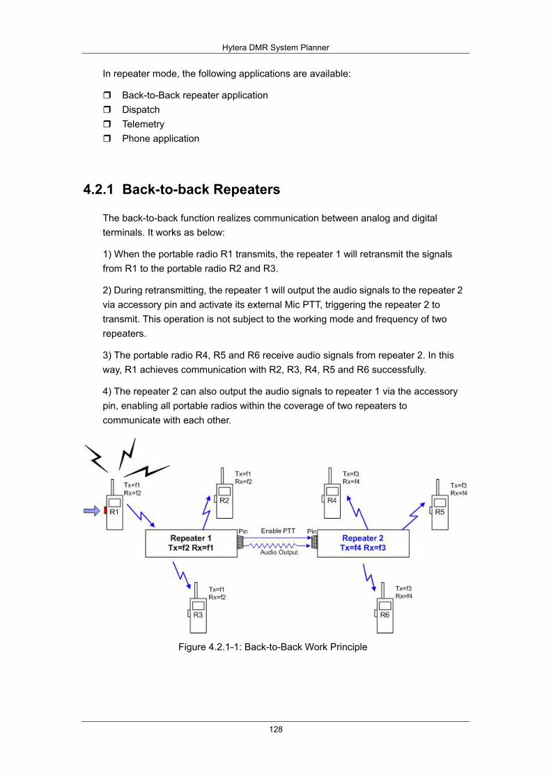
Hytera DMR System Planner
128
In repeater mode, the following applications are available:
Back-to-Back repeater application Dispatch Telemetry Phone application
4.2.1 Back-to-back Repeaters
The back-to-back function realizes communication between analog and digital terminals. It works as below:
1) When the portable radio R1 transmits, the repeater 1 will retransmit the signals from R1 to the portable radio R2 and R3.
2) During retransmitting, the repeater 1 will output the audio signals to the repeater 2 via accessory pin and activate its external Mic PTT, triggering the repeater 2 to transmit. This operation is not subject to the working mode and frequency of two repeaters.
3) The portable radio R4, R5 and R6 receive audio signals from repeater 2. In this way, R1 achieves communication with R2, R3, R4, R5 and R6 successfully.
4) The repeater 2 can also output the audio signals to repeater 1 via the accessory pin, enabling all portable radios within the coverage of two repeaters to communicate with each other.
Figure 4.2.1-1: Back-to-Back Work Principle
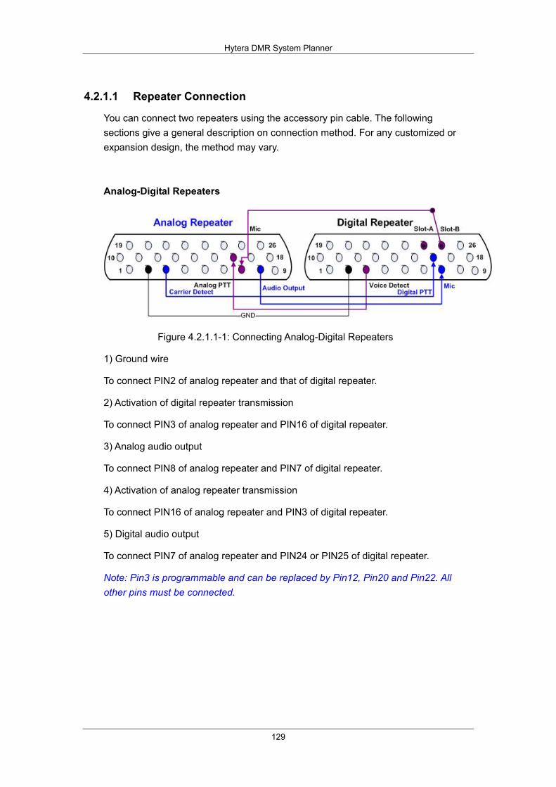
Hytera DMR System Planner
129
4.2.1.1 Repeater Connection
You can connect two repeaters using the accessory pin cable. The following sections give a general description on connection method. For any customized or expansion design, the method may vary.
Analog-Digital Repeaters
Figure 4.2.1.1-1: Connecting Analog-Digital Repeaters
1) Ground wire
To connect PIN2 of analog repeater and that of digital repeater.
2) Activation of digital repeater transmission
To connect PIN3 of analog repeater and PIN16 of digital repeater.
3) Analog audio output
To connect PIN8 of analog repeater and PIN7 of digital repeater.
4) Activation of analog repeater transmission
To connect PIN16 of analog repeater and PIN3 of digital repeater.
5) Digital audio output
To connect PIN7 of analog repeater and PIN24 or PIN25 of digital repeater.
Note: Pin3 is programmable and can be replaced by Pin12, Pin20 and Pin22. All other pins must be connected.
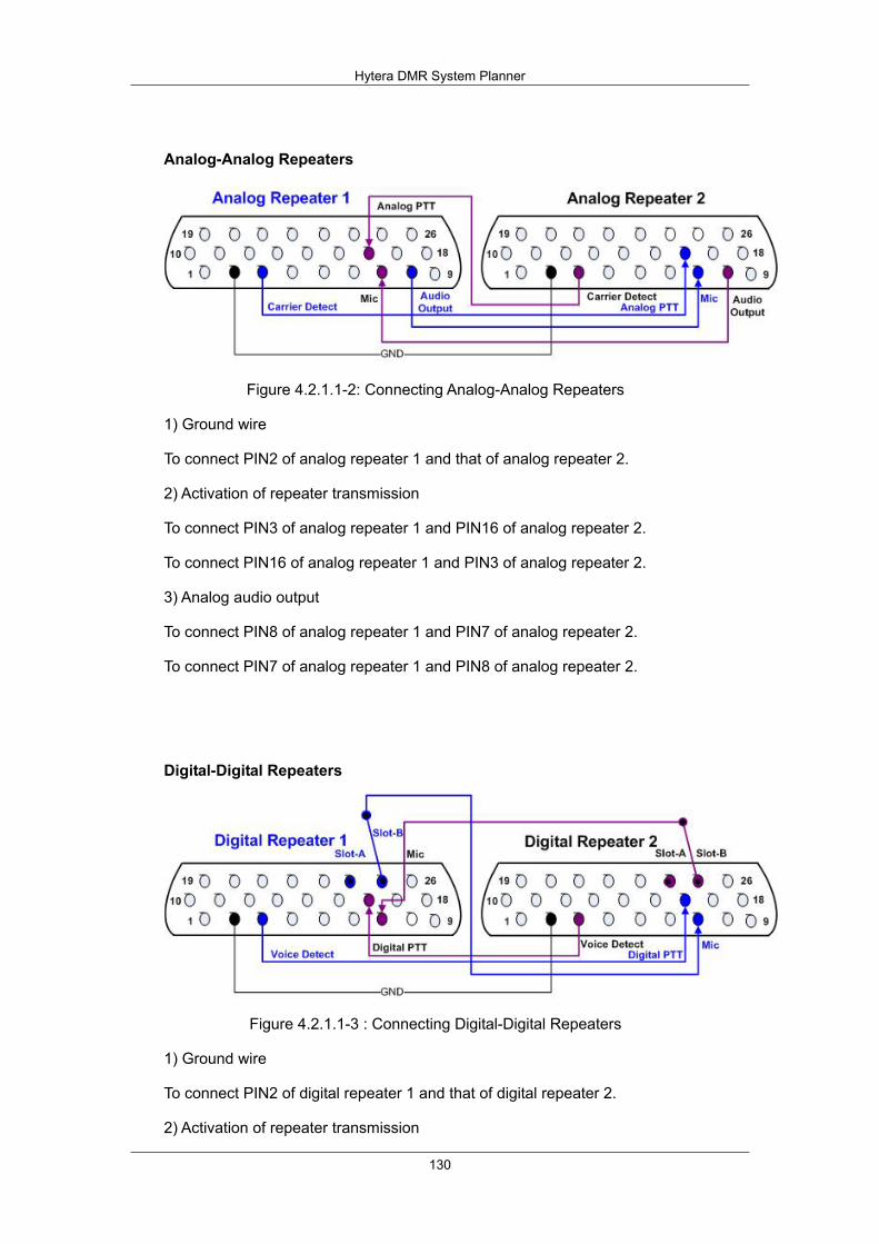
Hytera DMR System Planner
130
Analog-Analog Repeaters
Figure 4.2.1.1-2: Connecting Analog-Analog Repeaters
1) Ground wire
To connect PIN2 of analog repeater 1 and that of analog repeater 2.
2) Activation of repeater transmission
To connect PIN3 of analog repeater 1 and PIN16 of analog repeater 2.
To connect PIN16 of analog repeater 1 and PIN3 of analog repeater 2.
3) Analog audio output
To connect PIN8 of analog repeater 1 and PIN7 of analog repeater 2.
To connect PIN7 of analog repeater 1 and PIN8 of analog repeater 2.
Digital-Digital Repeaters
Figure 4.2.1.1-3 : Connecting Digital-Digital Repeaters
1) Ground wire
To connect PIN2 of digital repeater 1 and that of digital repeater 2.
2) Activation of repeater transmission
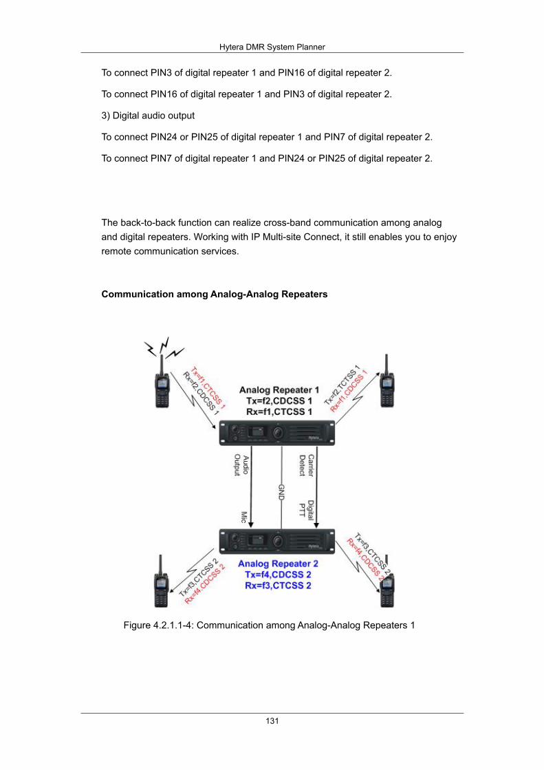
Hytera DMR System Planner
131
To connect PIN3 of digital repeater 1 and PIN16 of digital repeater 2.
To connect PIN16 of digital repeater 1 and PIN3 of digital repeater 2.
3) Digital audio output
To connect PIN24 or PIN25 of digital repeater 1 and PIN7 of digital repeater 2.
To connect PIN7 of digital repeater 1 and PIN24 or PIN25 of digital repeater 2.
The back-to-back function can realize cross-band communication among analog and digital repeaters. Working with IP Multi-site Connect, it still enables you to enjoy remote communication services.
Communication among Analog-Analog Repeaters
Figure 4.2.1.1-4: Communication among Analog-Analog Repeaters 1
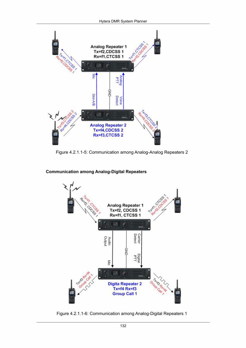
Hytera DMR System Planner
132
Figure 4.2.1.1-5: Communication among Analog-Analog Repeaters 2
Communication among Analog-Digital Repeaters
Figure 4.2.1.1-6: Communication among Analog-Digital Repeaters 1
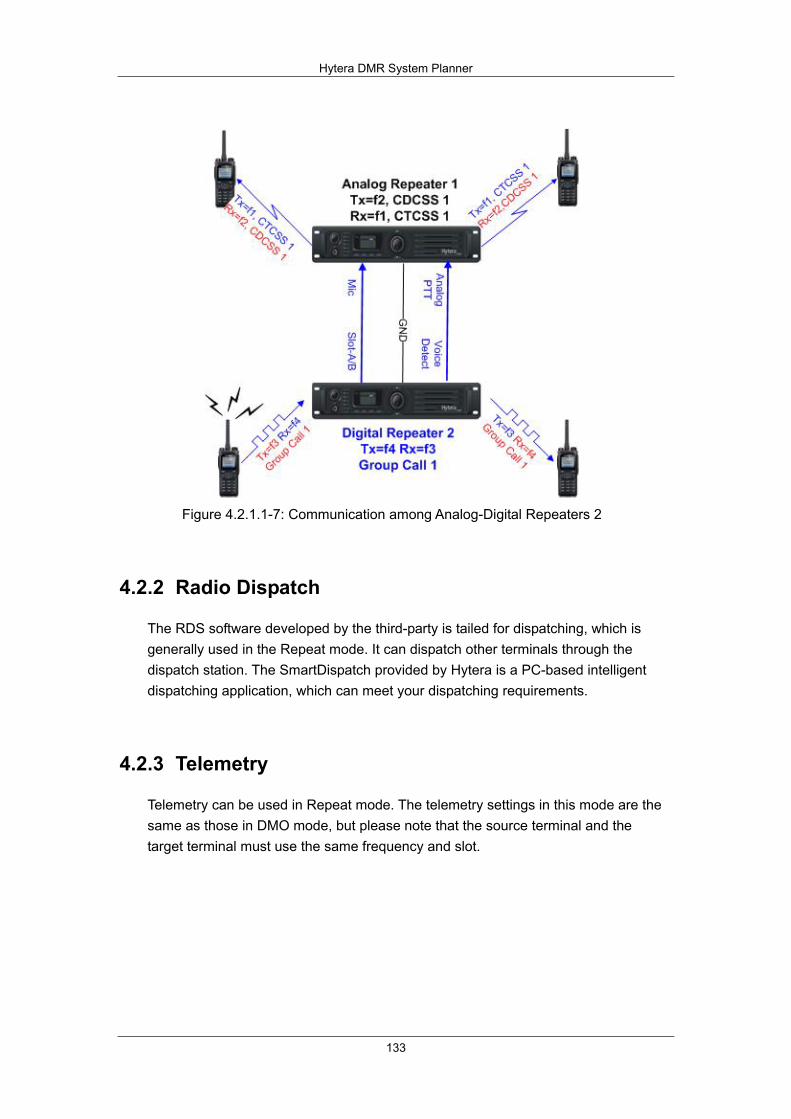
Hytera DMR System Planner
133
Figure 4.2.1.1-7: Communication among Analog-Digital Repeaters 2
4.2.2 Radio Dispatch
The RDS software developed by the third-party is tailed for dispatching, which is generally used in the Repeat mode. It can dispatch other terminals through the dispatch station. The SmartDispatch provided by Hytera is a PC-based intelligent dispatching application, which can meet your dispatching requirements.
4.2.3 Telemetry
Telemetry can be used in Repeat mode. The telemetry settings in this mode are the same as those in DMO mode, but please note that the source terminal and the target terminal must use the same frequency and slot.

Hytera DMR System Planner
134
Figure 4.2.3-1: Application of telemetry in Repeat mode
The figure above shows three kinds of telemetry features:
1) Querying the status of remote telemetry device. The source terminal and the target terminal share the same frequency, and use the same slot (slot1) to transmit or and receive. In Repeat mode, the source terminal sends Query Status Command to the target terminal via the repeater. After receiving the command, the target terminal will send its GPIO status to the source terminal so that users can get the current status of telemetry device remotely.
2) Controlling a remote device. In figure 5.2.2-1, the source terminal and the target terminal share the same frequency, and use the same slot (slot1) to communicate. In Repeat mode, the source terminal sends the telemetry command to the target terminal via the repeater. After receiving the command, the target terminal will change the GPIO status to control the telemetry device, and send the result to the source terminal. However, no reply will be given if the control command is sent via group call.
3) Uploading the GPIO status. In figure 5.2.2-1, the source terminal and the target terminal share the same frequency, and use the same slot (slot2) to communicate. When the status of connected external device changes, the GPIO status will change as well, which would trigger the source terminal to send the predefined telemetry command to the target terminal. In this way, you can get the status of foregoing device and perform related control operations.

Hytera DMR System Planner
135
4.3 IP Multi-site
IP Multi-site Connect is designed to extend the communication coverage by connecting multiple repeaters in dispersed locations over a TCP/IP-based network.
In IP Multi-site Connect mode, DMR protocol is transported by TCP/IP protocol and a Hytera-owned protocol at Application Layer. Accordingly, it is reasonable to conclude that this mode only changes the DMR transmission media without affecting the services of DMR terminals.
The figure below describes how IP Multi-site Connect works:
Figure 4.3-1: TCP/IP Model
Physical layer: the lowest layer of TCP/IP.
Network layer: also called IP layer. It is responsible for routing IP packets.
Transport layer: to set up a session between the source host and the
destination host. It consists of Transmission Control Protocol (TCP) and User
Datagram Protocol (UDP).
Application layer: to combine and realize the function of Session Layer and
Presentation Layer. It provides application-specific protocols.
As can be seen from the above figure, our IP Multi-site Connect function uses UDP at Transport Layer and self-owned transmission protocol at Application Layer. At Network Layer and Physical Layer, different protocols and devices may apply depending on actual
IP Multi-site Connect can bring users these typical benefits:
1) To connect two or more conventional communication systems in different areas.
For example, you can use this function to connect two repeaters over a large geographic area.
2) To construct a more effective communication area with wider coverage.
Hytera DMR System Planner
136
For example, you can deploy multiple repeaters in a large building to ensure seamless communication. This can help fight the problems from unfavorable terrains.
3) To broadcast a message to all connected repeaters.
For example, the dispatcher can send an instruction to all repeaters in IP Multi-site Connect mode in case of an emergency.
4) To connect repeaters working with varied frequency bands.
For example, UHF repeaters and VHF repeaters can be connected so that data and voice can be exchanged among them.
5) To use multiple IP-based applications.
For example, when IP Multi-site Connect is enabled, you can use multiple IP-based software (such as Dispatcher) as well as API-based software developed by any third party to realize more functions.
* Consult your dealer for more information on supported software.
* Consult your dealer for more information on development of API-based software.
Requirements on Network:
1) The IP network can either be a dedicated network or an internet provided by Internet Service Provider (ISP).
2) A number of technologies are supported by the ISPs, including dial-up, xDSL, cable modem, broadband wireless access, canopy, ISDN, satellite internet access, and so on. Currently, the IP network is not applicable to dial-up connection due to narrow bandwidth or satellite internet access due to large delay.
3) Sufficient bandwidth is required for IP network.
4) In IP network, there must be a static IP address and UDP port for Master repeater and Slave repeater. For the latter, it is unnecessary to fix its IP address and UDP port.
5) The repeater can locate behind the firewall, router or NAT.
6) IP address instead of proxy server shall be used to access the WAN.

Hytera DMR System Planner
137
4.3.1 Network Topology of IP Multi-site Connect
The network topology of IP Multi-site Connect can operate with many networks or can connect all Wide Area Channels (WACH) via a physical network, depending upon the repeater location and the network connection. Typically, there are two kinds of network topologies:
Local area network (LAN)
Wide area network (WAN)
In most cases, LAN and WAN together constitute the network topology. In the following sections, details on LAN and WAN will be given respectively.
* The same network configurations may apply to analog/digital repeaters, enabled/disabled repeaters, wide area/local repeaters or any device developed by a third party based on IP Multi-site Connect protocols.
4.3.2 Local Area Network
In IP Multi-site Connect mode, these networks are supported:
Dedicated LAN
A company’s LAN
Dedicated radio communication system
Despite variable LAN configurations, the IP Multi-site Connect network system can work properly once all devices are in the same LAN or connected to some other networks via a router or NAT. In order for the system to operate at its best, however, the technicians must have a good knowledge of bandwidth required by related devices.
Additionally, only the Master repeater needs a static IPv4 address, which the other network devices can use to connect the wide area system.
The following figure shows an example of IP Multi-site Connect operating with LAN. Note that the network devices may belong to different wide area systems, for example, there are multiple dispatching centers.

Hytera DMR System Planner
138
Network
IP Multi-site Connect Device
LAN
IP Multi-site Connect Device
IP Multi-site Connect Device
IP Multi-site Connect Device
IP Multi-site Connect Device
IP Multi-site Connect Device
Figure 4.3.2-1: IP Multi-site Connect Network Operating with LAN
4.3.3 Wide Area Network (WAN)
The biggest advantage of IP Multi-site Connect lies in that it can connect dispersed sites quickly through the internet provided by an ISP, which provides a range of technologies for IP Multi-site Connect:
Dedicated T1
DSL (typically ADSL)
Cable modem
Broadband wireless access such as Canopy
ISDN
Frame relay
others
At present, the IP network is not applicable to dial-up connection due to narrow bandwidth or satellite internet access due to large delay. In order for the system to operate at its best, the system engineering personnel must have a good knowledge
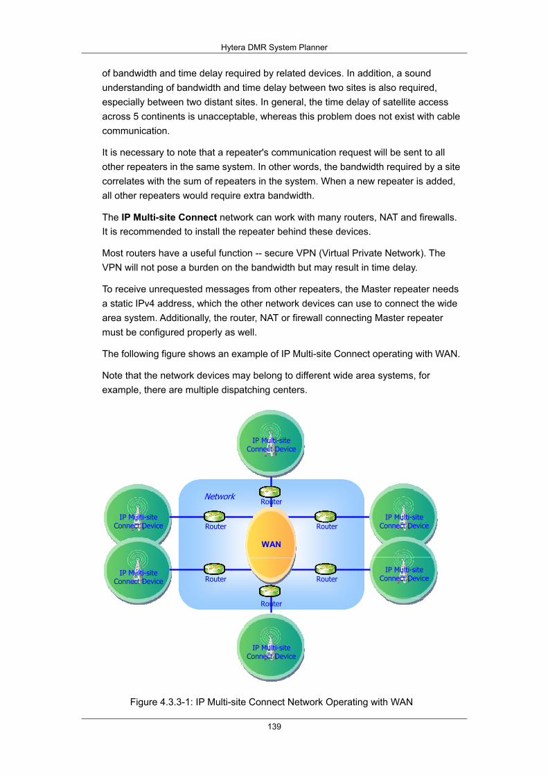
Hytera DMR System Planner
139
of bandwidth and time delay required by related devices. In addition, a sound understanding of bandwidth and time delay between two sites is also required, especially between two distant sites. In general, the time delay of satellite access across 5 continents is unacceptable, whereas this problem does not exist with cable communication.
It is necessary to note that a repeater's communication request will be sent to all other repeaters in the same system. In other words, the bandwidth required by a site correlates with the sum of repeaters in the system. When a new repeater is added, all other repeaters would require extra bandwidth.
The IP Multi-site Connect network can work with many routers, NAT and firewalls. It is recommended to install the repeater behind these devices.
Most routers have a useful function -- secure VPN (Virtual Private Network). The VPN will not pose a burden on the bandwidth but may result in time delay.
To receive unrequested messages from other repeaters, the Master repeater needs a static IPv4 address, which the other network devices can use to connect the wide area system. Additionally, the router, NAT or firewall connecting Master repeater must be configured properly as well.
The following figure shows an example of IP Multi-site Connect operating with WAN.
Note that the network devices may belong to different wide area systems, for example, there are multiple dispatching centers.
IP Multi-site Connect Device
NetworkRouter
Router
Router
Router
Router
Router
WAN
IP Multi-site Connect Device
IP Multi-site Connect Device
IP Multi-site Connect Device
IP Multi-site Connect Device
IP Multi-site Connect Device
Figure 4.3.3-1: IP Multi-site Connect Network Operating with WAN
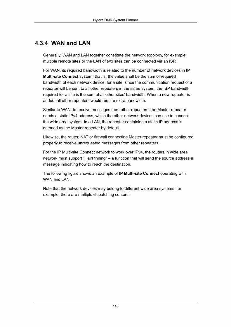
Hytera DMR System Planner
140
4.3.4 WAN and LAN
Generally, WAN and LAN together constitute the network topology, for example, multiple remote sites or the LAN of two sites can be connected via an ISP.
For WAN, its required bandwidth is related to the number of network devices in IP Multi-site Connect system, that is, the value shall be the sum of required bandwidth of each network device; for a site, since the communication request of a repeater will be sent to all other repeaters in the same system, the ISP bandwidth required for a site is the sum of all other sites’ bandwidth. When a new repeater is added, all other repeaters would require extra bandwidth.
Similar to WAN, to receive messages from other repeaters, the Master repeater needs a static IPv4 address, which the other network devices can use to connect the wide area system. In a LAN, the repeater containing a static IP address is deemed as the Master repeater by default.
Likewise, the router, NAT or firewall connecting Master repeater must be configured properly to receive unrequested messages from other repeaters.
For the IP Multi-site Connect network to work over IPv4, the routers in wide area network must support ”HairPinning” – a function that will send the source address a message indicating how to reach the destination.
The following figure shows an example of IP Multi-site Connect operating with WAN and LAN.
Note that the network devices may belong to different wide area systems, for example, there are multiple dispatching centers.
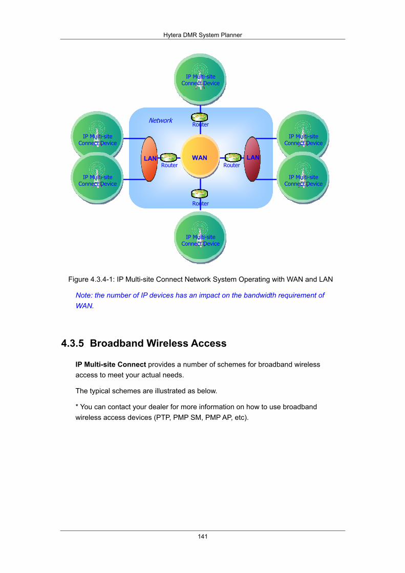
Hytera DMR System Planner
141
IP Multi-site Connect Device
NetworkRouter
Router Router
Router
广域网LAN WAN LAN
IP Multi-site Connect Device
IP Multi-site Connect Device
IP Multi-site Connect Device
IP Multi-site Connect Device
IP Multi-site Connect Device
Figure 4.3.4-1: IP Multi-site Connect Network System Operating with WAN and LAN
Note: the number of IP devices has an impact on the bandwidth requirement of WAN.
4.3.5 Broadband Wireless Access
IP Multi-site Connect provides a number of schemes for broadband wireless access to meet your actual needs.
The typical schemes are illustrated as below.
* You can contact your dealer for more information on how to use broadband wireless access devices (PTP, PMP SM, PMP AP, etc).

Hytera DMR System Planner
142
4.3.5.1 Point-to-Point (PTP) and Ethernet Cable
Figure 4.3.5.1-1: By Point-to-Point (PTP) and Ethernet Cable
4.3.5.2 Point-to-Point (PTP) and Local Area Network (LAN)
Figure 4.3.5.2-1: By Point-to-Point (PTP) and Local Area Network (LAN)

Hytera DMR System Planner
143
4.3.5.3 Point-to-Point (PTP) Cluster and Local Area Network (LAN)
Figure 4.3.5.3-1: By Point-to-Point (PTP) Cluster and Local Area Network (LAN)
4.3.5.4 Point-to-Point (PTP) and Wide Area Network (WAN)
Figure 4.3.5.4-1:By Point-to-Point (PTP) and Wide Area Network (WAN)

Hytera DMR System Planner
144
4.3.5.5 Point-to-Multipoint (PMP) and Wide Area Network (WAN)
Figure 4.3.5.5-1: By Point-to-Multipoint (PMP) and Wide Area Network (WAN)
4.3.5.6 Point-to-Multipoint (PMP) Cluster and Local Area Network (LAN)
Figure 4.3.5.6-1: Point-to-Multipoint (PMP) Cluster and Local Area Network (LAN)
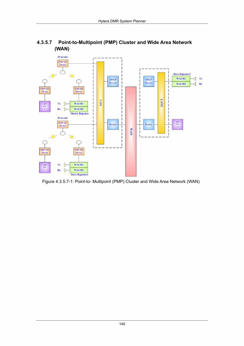
Hytera DMR System Planner
145
4.3.5.7 Point-to-Multipoint (PMP) Cluster and Wide Area Network (WAN)
Figure 4.3.5.7-1: Point-to- Multipoint (PMP) Cluster and Wide Area Network (WAN)
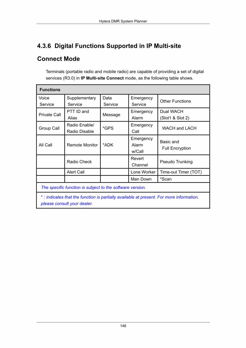
Hytera DMR System Planner
146
4.3.6 Digital Functions Supported in IP Multi-site
Connect Mode
Terminals (portable radio and mobile radio) are capable of providing a set of digital services (R3.0) in IP Multi-site Connect mode, as the following table shows.
Functions
Voice Service
Supplementary Service
Data Service
Emergency Service
Other Functions
Private Call PTT ID and Alias
Message Emergency Alarm
Dual WACH (Slot1 & Slot 2)
Group Call Radio Enable/ Radio Disable
*GPS Emergency Call
WACH and LACH
All Call Remote Monitor *ADK Emergency Alarm w/Call
Basic and Full Encryption
Radio Check Revert Channel
Pseudo Trunking
Alert Call Lone Worker Time-out Timer (TOT) Man Down *Scan
The specific function is subject to the software version.
* : indicates that the function is partially available at present. For more information, please consult your dealer.
Hytera DMR System Planner
147
4.4 Access Management
The Access Management is designed for the conventional communication system. It has two management types: Local Access Management and Multi-site Access Management. The former is to prevent the radio beyond the ID range from accessing the repeater, while the latter is to repeat the right data to the radio satisfying the predefined conditions over IP network.
In Local Access Management mode, as the repeater in sleep status receives the reviving code from the radio, it will determine whether this radio ID is within its ID range. If yes, the service data will be repeated. When the repeater is activated, it will analyze the received data from the radio to determine whether this radio ID is within its ID range. If yes, the service data will be repeated.
In IP Multi-site Connect system, when one repeater receives service requests from the radio, it will transfer them to each repeater in the system over IP network to determine whether the access is granted. In this case, there is only one group of call in progress at a time, which wastes radio resources. However, the Multi-site Access Management feature helps you to address the above problem and realize point-to-point communication.
The Access Manager is designed for the conventional communication system. It has two management types: Local Access Management and Multi-site Access Management. The former is to prevent the radio beyond the ID range from accessing the repeater, while the latter is to repeat the right data to the radio satisfying the predefined conditions over IP network.

Hytera DMR System Planner
148
4.4.1 Local Access Management
The Local Access Management feature is applicable to a local repeater. It ensures that access is granted to a radio whose ID is within the ID range only. See Figure as below:
Figure 4.4.1-1: Local Access Management Example
From the above diagram, you can see that MS1’s ID and MS3’s ID are within the ID range of the repeater, while MS2’s ID is beyond that range. Thus, the repeater will repeat call and data requests from MS1 and MS3 rather than MS2, because MS2 is deemed illegal.

Hytera DMR System Planner
149
4.4.2 Multi-site Access Management
The Multi-site Access Management feature is used to repeat the satisfied data to the designated radio over IP Multi-site Connect. See Figure as below:
Figure 4.4.2-1: Multi-site Access Management Example
From above diagram, when both MS2 and MS3 make a private call (ID401) respectively, this call request will be transmitted to all repeaters in the system over IP Multi-site Connect. However, no repeater will grant access to this request, because this private call ID is beyond the private call ID range of all repeaters. When MS1makes a private call (ID301) to MS4, the repeater (BS4) will repeat it. That is because this private call ID is within the private call ID range of this repeater.
Consequently, MS1 is entitled to communicate with MS4.
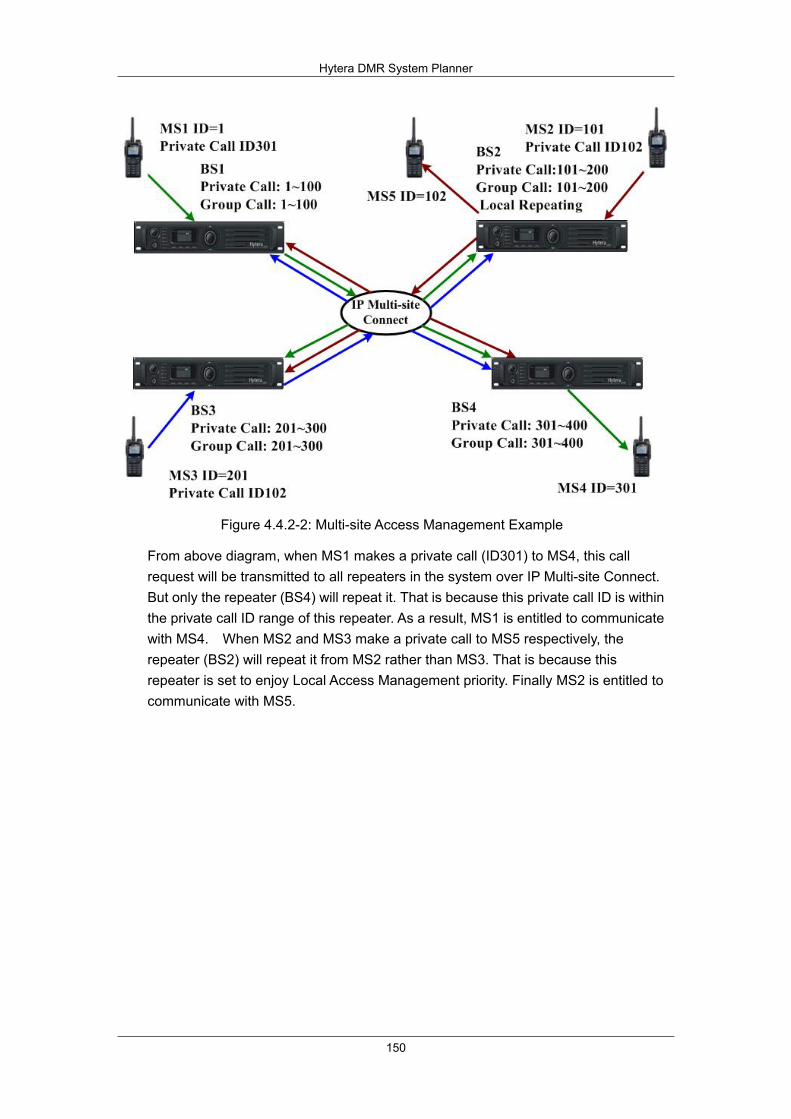
Hytera DMR System Planner
150
Figure 4.4.2-2: Multi-site Access Management Example
From above diagram, when MS1 makes a private call (ID301) to MS4, this call request will be transmitted to all repeaters in the system over IP Multi-site Connect. But only the repeater (BS4) will repeat it. That is because this private call ID is within the private call ID range of this repeater. As a result, MS1 is entitled to communicate with MS4. When MS2 and MS3 make a private call to MS5 respectively, the repeater (BS2) will repeat it from MS2 rather than MS3. That is because this repeater is set to enjoy Local Access Management priority. Finally MS2 is entitled to communicate with MS5.

Hytera DMR System Planner
151
Figure 4.4.2-3: Multi-site Access Management Example
From above diagram, when MS1 makes a private call (ID301) to MS4, this call request will be transmitted to all repeaters in the system over IP Multi-site Connect. But only the repeater (BS4) will repeat it. That is because this private call ID is within the private call ID range of this repeater. As a result, MS1 is entitled to communicate with MS4.When MS2 and MS3 make a call to MS5 respectively, the repeater (BS2) will repeat it from MS3 rather than from MS2. That is because this repeater is set to enjoy Multi-site Access Management priority. Finally MS3 is entitled to communicate with MS5.
Hytera DMR System Planner
152
4.5 Repeat request priority
The repeat request priority feature is designed to solve the priority classifying problems in repeater transferring in multi-site system. The repeater will receive the data from the network and the signals over the air. When it receives both at the same time, which shall it transfer first? To solve this problem, Hytera DMR provides the Multi-site Priority feature, so you can define the priority to the signals or data to be transferred by the repeater.
This feature is usually used with the access management to make the use of the system resources more convenient and reasonable.
4.6 Super Master
The Super Master feature is tailored for connecting multiple Master Repeaters in the IP Multisite Connect mode, expanding the communication coverage of IP network.
Currently, the single IP network can accommodate a maximum of 30 repeaters including a Master Repeater and multiple Slave Repeaters. In the multi-layer network, as the monolayer structure in the IP Multisite Connect network is adopted, the Master Repeater will be only allowed to communicate with its Slave Repeaters within the network rather than other Master Repeaters in other single networks, making it difficult to expand communication coverage of the IP network. In this case, if you need to extend the coverage without changing the existing IP network, it entails the connection of Master Repeaters in different single networks. Here, the Super Master can address the above problem. To be specific, this feature can be used in both the Star Network and Double-layer Network, to extend the communication coverage. In the former mode, any Master Repeater in the IP Multisite Connect network can work as a Super Master, to connect with other Master Repeaters in other single networks. Theoretically, this IP network can accommodate an unlimited number of repeaters. In the latter mode, only one Super Master is available, to connect other Master Repeaters. And a maximum of 225 repeaters can be deployed in this network.
In addition to the existing IP network service, the super master service, super master Multisite service and super master RDAC service are also available to meet the customer’s needs.
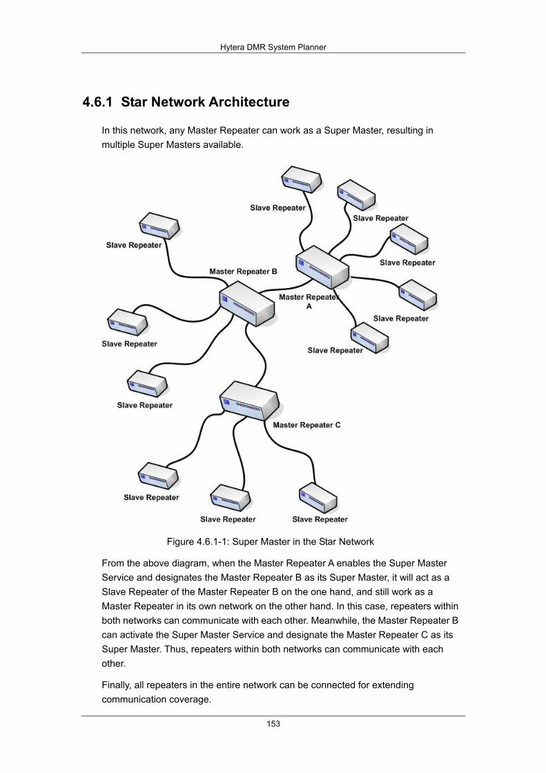
Hytera DMR System Planner
153
4.6.1 Star Network Architecture
In this network, any Master Repeater can work as a Super Master, resulting in multiple Super Masters available.
Figure 4.6.1-1: Super Master in the Star Network
From the above diagram, when the Master Repeater A enables the Super Master Service and designates the Master Repeater B as its Super Master, it will act as a Slave Repeater of the Master Repeater B on the one hand, and still work as a Master Repeater in its own network on the other hand. In this case, repeaters within both networks can communicate with each other. Meanwhile, the Master Repeater B can activate the Super Master Service and designate the Master Repeater C as its Super Master. Thus, repeaters within both networks can communicate with each other.
Finally, all repeaters in the entire network can be connected for extending communication coverage.

Hytera DMR System Planner
154
4.6.2 Double-layer Network Architecture
In this network, there is only one Super Master available.
Figure 4.6.2-1: Super Master in the Double-layer Network
From the above diagram, you can see that the Master Repeater A works as a Super Master and has three Slave Repeaters including Master Repeater B, Master Repeater C and Master Repeater D.
All repeaters in the entire network can communicate with each other. Please note that the total number of the Super Master, Master Repeater and Slave Repeater in a single network cannot exceed 30. As a result, the entire network can accommodate 225 repeaters at most.
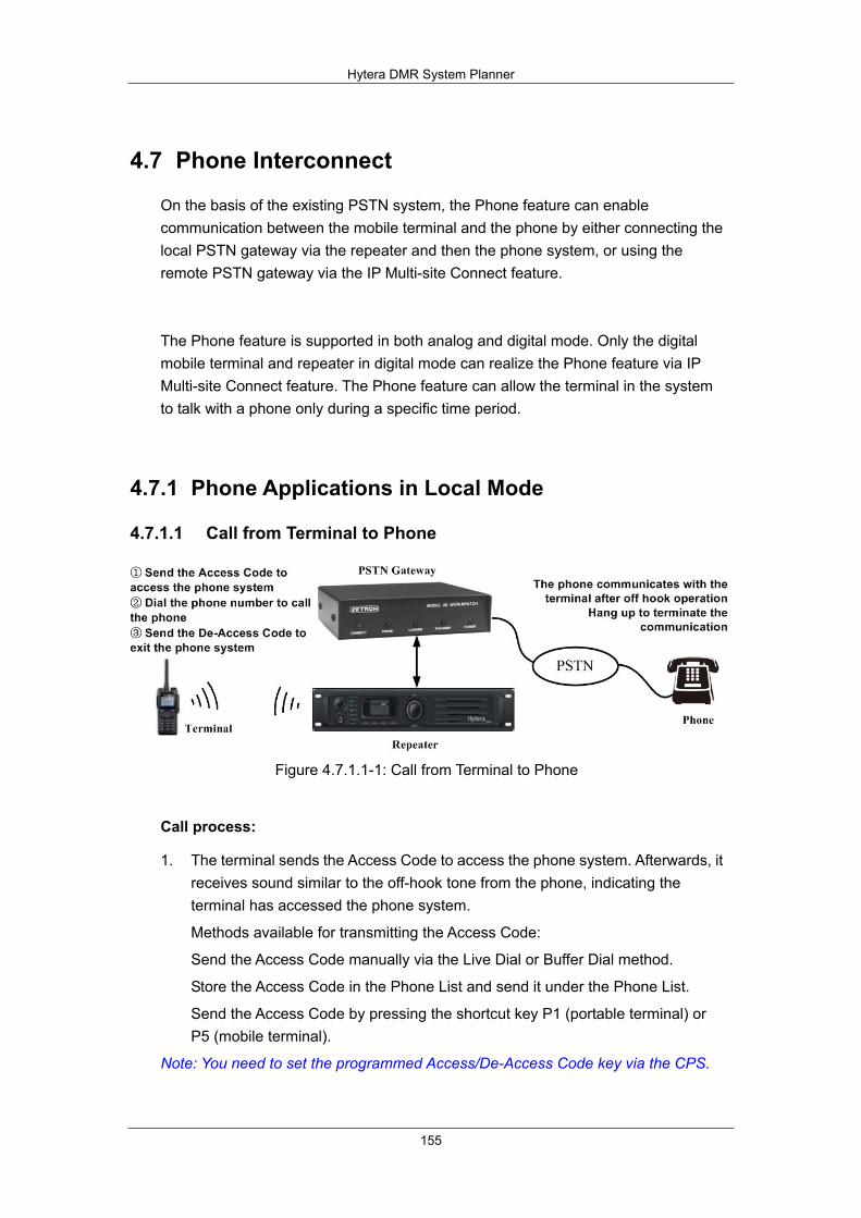
Hytera DMR System Planner
155
4.7 Phone Interconnect
On the basis of the existing PSTN system, the Phone feature can enable communication between the mobile terminal and the phone by either connecting the local PSTN gateway via the repeater and then the phone system, or using the remote PSTN gateway via the IP Multi-site Connect feature.
The Phone feature is supported in both analog and digital mode. Only the digital mobile terminal and repeater in digital mode can realize the Phone feature via IP Multi-site Connect feature. The Phone feature can allow the terminal in the system to talk with a phone only during a specific time period.
4.7.1 Phone Applications in Local Mode
4.7.1.1 Call from Terminal to Phone
Figure 4.7.1.1-1: Call from Terminal to Phone
Call process:
1. The terminal sends the Access Code to access the phone system. Afterwards, it receives sound similar to the off-hook tone from the phone, indicating the terminal has accessed the phone system.
Methods available for transmitting the Access Code:
Send the Access Code manually via the Live Dial or Buffer Dial method.
Store the Access Code in the Phone List and send it under the Phone List.
Send the Access Code by pressing the shortcut key P1 (portable terminal) or P5 (mobile terminal).
Note: You need to set the programmed Access/De-Access Code key via the CPS.

Hytera DMR System Planner
156
2. Dial the phone number. Methods available for dialing the required phone number:
Dial the phone number manually via the Live Dial or Buffer Dial method.
Select a phone number from the Phone List and dial it.
3. After the phone number of the destination party is sent, the terminal receives an alert (including waiting tone, busy tone and voice alert) consistent with the phone system, indicating the terminal is connecting the phone.
4. After the off-hook operation on the phone, the terminal can communicate with the phone via the PTT key.
5. Terminate the communication. Two methods available for terminating the communication:
Hang up the phone.
The terminal sends the De-Access Code through the following methods:
Send the De-Access Code manually via the Live Dial or Buffer Dial method.
Store the De-Access Code in the Phone List and send it under the Phone List.
Send the De-Access Code by pressing the shortcut key P2 (portable terminal) or P6 (mobile terminal).
Note: During a call from the terminal to the phone, the terminal displays the TX contact name and phone number. You must set a TX contact; otherwise, the terminal cannot make call services.
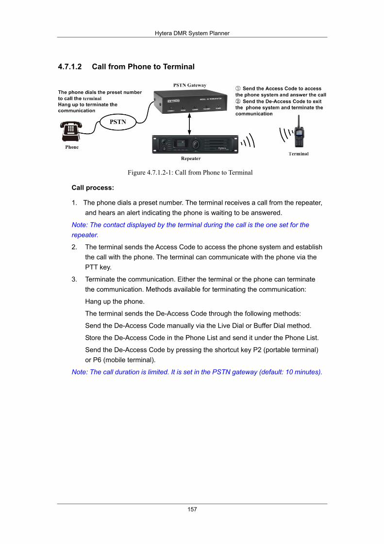
Hytera DMR System Planner
157
4.7.1.2 Call from Phone to Terminal
Figure 4.7.1.2-1: Call from Phone to Terminal
Call process:
1. The phone dials a preset number. The terminal receives a call from the repeater, and hears an alert indicating the phone is waiting to be answered.
Note: The contact displayed by the terminal during the call is the one set for the repeater.
2. The terminal sends the Access Code to access the phone system and establish the call with the phone. The terminal can communicate with the phone via the PTT key.
3. Terminate the communication. Either the terminal or the phone can terminate the communication. Methods available for terminating the communication:
Hang up the phone.
The terminal sends the De-Access Code through the following methods:
Send the De-Access Code manually via the Live Dial or Buffer Dial method.
Store the De-Access Code in the Phone List and send it under the Phone List.
Send the De-Access Code by pressing the shortcut key P2 (portable terminal) or P6 (mobile terminal).
Note: The call duration is limited. It is set in the PSTN gateway (default: 10 minutes).

Hytera DMR System Planner
158
4.7.2 Phone Applications in IP Multi-site Connect Mode
The Phone feature can be used in the IP Multi-site Connect mode. See Figure below:
Figure 4.7.2-1: Call from Terminal to Phone in IP Multi-site Connect Mode
Figure 47.2-2: Call from Phone to Terminal in IP Multi-site Connect Mode
The procedures and process for using the Phone feature are the same in the IP Multi-site Connect mode and the local mode. For details, please refer to the section “4.7.1 Phone Applications in Local Mode”. In the IP Multi-site Connect mode, it is recommended to connect one repeater to the PSTN gateway only.

159
5 DMR System Considerations This chapter introduces the System software version Compatible and function interaction.
5.1 Important notes of R4.0 update
5.1.1 Subscriber
1. Please note that the SELP version of R3.5 and R4.0 software are not interoperable. As such, it is recommended to have all the system (subscriber and repeaters) upgraded to the same release if interoperability is required as only same versions of the vocoder is able to encode/decode the voice correctly.
2. Please note that roaming is disabled when it is shipped from factory in R4.0.
(Please contact your nearest sales support to get more information on this! Considering this feature is free for trial usage in R3.5, as such, for users who perform software upgrade to R4.0, they can still enjoy the roaming feature for free after the upgrade!)
3. Please note that SELP vocoder is not able to encode a demodulated voice correctly, During in Analog/Digital back-to-back operation, the audio repeated from digital is bad. The audio will be distorted while talking. We have fixed and closed this issue in R4.5 version.
5.1.2 Repeater
1. Please note that due to the enhancement in Multi-site framework to ease the network administrator installation of slave repeaters in LAN without needing to set the port forwarding, this has caused the R3.5 repeater to not be able to communicate with R4.0 repeater. As such, for user who are using IP Multi-Site Connect, it is recommended to have all the repeaters upgraded to the same software for interoperability.
2. Please note that SELP vocoder is not able to encode a demodulated voice correctly, During in Analog/Digital back-to-back operation, the audio repeated from digital is bad. The audio will be distorted while talking. We have fixed and closed this issue in R4.5 version.
Hytera DMR System Planner
160
5.1.3 Interaction between Subscriber and Repeater
1. Please note that to achieve better call performance under interference, R4.0 subscriber shall only be used with R4.0 repeater. Note that R4.0 subscriber will not perform optimally with R3.5 repeater. However, using a R3.5 subscriber will be able to work properly with a R4.0 repeater. As such, when you have some additional subscriber order to existing R3.5 system, please contact your nearest sales support/customer service to get more assistance.
5.2 Important notes of R4.5 update
5.2.1 Subscriber
1. The R4.5 subscriber is interoperable with R4.0/R4.1 repeater, and it will be able to work properly with R4.0/R4.1 repeater.
5.2.2 Repeater
1. R4.5 repeater is interoperable with R4.0/R4.1 repeater, and it will be able to work properly with R4.0/R4.1 repeater.
5.2.3 Interaction between Subscriber and Repeater
1. To operate Priority interrupt, the repeater needs to be upgraded to R4.5 to be compatible.
Hytera DMR System Planner
161
5.3 Function interaction
5.3.1 Phone Interconnect
To use the Phone feature, you need to enable it for the terminal in the CPS and set appropriate Access Code and De-Access Code. To call the phone, please send the Access Code to access the phone system first. To exit the phone system, please send the De-Access Code to terminate the communication and exit the phone system. The call from the terminal to the phone is also subject to the TX Admit settings. The terminal can make calls only when it complies with the TX Admit settings. The terminal can call the phone only when the terminal, repeater and PSTN gateway are correctly set, and the terminal complies with the TX Admit settings. For a call from the phone to the terminal, the terminal needs to send the Access Code before answering it.
The Phone feature can be used in either digital or analog mode. In digital mode, private call, group call and all call can be made between the terminal and the phone. However, for a call from the phone to the terminal, its call type must correspond to the TX contact set for the repeater.
Does the Phone feature affect the terminal’s conventional communication, no. This feature only allows the phone to communicate with the terminal in the communication system via the PSTN gateway. For a call from the terminal to the phone, the terminal sends call request and voice to the repeater. Then such request data and voice are repeated by the repeater to the PSTN gateway, and then to the phone. The call from the terminal to the phone or vice versa is the same as the conventional communication.
How to configure the TX Admit for the terminal.
Analog Channel: Select “Always Allow” for the “TX Admit” parameter.
Digital Channel: If the TX contact for the repeater is an all call contact, select “Always Allow” for the "TX Admit" parameter on the digital channel setting interface. If it is not an all call contact, the “Color Code Free” option is recommended. During call receiving, please select the “Always Allow” option.
Please do not check the "Encrypt” parameter for the digital terminal, because the repeater does not support the Decrypt feature. If checked, the communication may get affected.
If one terminal sends the Access Code, all the other terminals can talk with the phone. In this way, the communication between the phone and the terminal sending the access code may be affected. Therefore, it is suggested to make different TX Admit settings for the terminals.

Hytera DMR System Planner
162
5.3.2 Encryption
Can both encryption mechanisms apply to one terminal? Yes, but each channel supports one mechanism only.Hytera. Hytera provide three options: 40 bits, 128 bits and 256 bits.
Will encryption affect the communication coverage and voice quality? No at all.
Will the encryption settings work for both parties operating on the same channel? Yes, but the Encrypt option applies to the transmitting party only, that is, if this option is checked, the data to be transferred will be encrypted; otherwise, the data will not be encrypted.
Can A Radio with Hytera Encryption and That with DMRA Encryption Communicate with Each Other?
No, they cannot communicate with each other, because of the different ways in the key generation and embedding, as well as processing the encryption parameters between Hytera encryption and DMRA encryption. Advanced encryption provides two types of protocols: Hytera encryption and DMRA encryption. Hytera encryption adopts the encryption algorithm innovated by itself, and DMRA encryption is DMR standard encryption.
5.3.3 Pseudo Trunking
Pseudo Trunk supports conventional voice and data services, including call, SMS and auxiliary function. The auxiliary function mainly consists of Alarm, Radio Check, Call Alert, Kill/Activate, Priority Interrupt, etc. In R5.0, Telemetry will be supported.
In Direct mode, the slots on the channel are assigned dynamically. Slot 1 is used by default. While in Repeater mode, the slots are fixed, and the repeater is used for transferring the received voice signals and data. Comparatively, in Direct mode, the subscriber will select the time slot dynamically for transmission. The first used slot will be taken as Slot 1, and the latter one to be used is considered Slot 2. While in Repeater mode, Slot 1 and Slot 2 are fixed, but the subscriber, except the one that has designated the Pseudo Trunk Tx slot, can use any one of them for transmission.
Pseudo trunking supports the Alarm or GPS Revert Channel setting on Pseudo Trunk channel, but these settings are not suggested. Pseudo Trunk mode has dynamic time slots to choose, so the variable of the related services needs to be backed up sometimes in Slot 1 and sometimes Slot 2. This is complicated. Since the Alarm and GPS Revert Channel services require stable slots, so they are not suggested to be used on Pseudo Trunk channel.

Hytera DMR System Planner
163
5.3.4 Priority Interrupt
Pseudo Trunk is a bi-slotted work mode allowing the subscriber to work in two slots, while Priority Interrupt is a function only working in Pseudo Trunk mode. The interrupting subscriber can only use one slot to transmit the voice signals, leading to the misunderstanding that Pseudo Trunk cannot support bi-slotted work mode with Priority Interrupt. Actually Pseudo Trunk still works in bi-slotted mode, and Priority Interrupt just embodies it: In the process of the interruption operation, one slot is being used for a call, so the other must be free for the command transmission. Once both slots are occupied, the command may fail, so you will need corresponding configuration before the operation.
The Priority Interrupt command may fail to interrupt the ongoing call on the channel by three main causes:
Cause 1: The subscribers are not configured correctly or completely. The function requires the respective configuration on the interrupting and the interrupted subscribers, and different interruptions need different configuration, otherwise, the interruption will fail.
Cause 2: The channel is occupied. The subscriber configured with Priority Interrupt feature can only use one channel to transmit voice services. However, in actual use in the system, there may be some subscribers not configured with this feature or even Pseudo Trunk, so there may be two channels occupied. In this case, the Priority Interrupt commands can be transmitted but may not work.
Cause 3: The activity on the channel is a data service, which is not allowed to be interrupted.
Apart from the above causes, there is little failure caused by system error. Thus, if your encounter other causes except these three, please transmit the command again.
Interaction between Priority Interrupt and Other Features
1. Interaction with Pseudo Trunk Designated Tx: Once Pseudo Trunk Tx slot is designated, the voice signals or data services must be transmitted in the designated slot after the Priority Interrupt command transmission, whether the interrupt succeeds or not.
2. Interaction with Call Back: Whether the Pseudo Trunk Tx slot is designated, the Call Back after the interruption will be made in the call-receiving slot.
Hytera DMR System Planner
164
3. Interaction with the repeater: Priority Interrupt is supported within Call Hold of the repeater. If the repeater is transferring voice signals or term and detects Priority Interrupt data in the other slot, Call Hold in the Tx slot of the repeater will be interrupted, and the repeater will enter channel hold time and send information to the channel that it is free.
4. Interaction with Phone feature: Phone doesn’t support Priority Interrupt.
5. Interaction with Repeater: Priority Interrupt doesn’t work between the subscriber in Direct mode and that in Repeater mode, as the interference between the subscriber and the repeater may lead to the failure to detect the interruption data.
6. Compatibility with MOR: The subscriber with Priority Interrupt is not able to use MOR. The subscriber set to MOR via the optional board can only apply either MOR or Priority Interrupt at one time.
7. Interaction with Roam: When the subscriber is roaming, the application of this feature requires the designated slot and the Priority Interrupt Encode/Decode configuration of the subscriber’s channel to be corresponding to the configuration of the master site, otherwise, Priority Interrupt or the decoding will fail.
8. Interaction with Scan: When Scan is on, if the subscriber initiates Priority Interrupt on the channel where it is staying, it must enable Talk Back option first, otherwise, whether to initiate will depend on the Tx channel designated by Scan Tx Mode. Neither Emergency Priority Interrupt nor Message Priority Interrupt will interact with Scan, as the subscriber will exit from Scan when it is to make emergency call operation or to send a message.
9. Interaction with VOX: Priority Interrupt doesn’t support VOX, and it cannot be enabled via VOX.
Note: Different from conventional Priority Interrupt, MOR is a special Priority Interrupt for railway system.
Hytera DMR System Planner
165
5.3.5 Roaming
The Roaming and Scan features can not be set for the same channel. The Scan feature is mainly used in direct mode or Repeater mode to scan channels in the scan list, while the Roaming feature is mainly used in the IP Multi-site Connect network to scan channels in the Roam list. Therefore, the Roaming feature is not the Scan feature for the conventional communication system.
the Roaming feature requires specific use environments. Generally, communication made on the master site will not be affected. If the terminal moves from one site to another while communicating, the communication will be interrupted because the terminal needs to connect to the repeater again.
However, the communication quality will be the same no matter which site the terminal operates on.
Communication services such as voice and data cannot be made during roaming. The Roaming feature requires the terminal to searches different channels continuously, while communication services require a specific channel. Therefore, the Roaming feature and communication services cannot be executed simultaneously.
In summary, the mutual influence between the Roaming and communication services mainly depends on the specific use environments.

Hytera DMR System Planner
166
5.3.6 IP Multi-site Connect
How to select frequency and color code in IP Multi-site Connect network? You can select the proper networking scheme as per your actual needs. In the overlapping area, it is recommended that the frequency of the repeater be different, but the color code can be the same or varied. For adjacent repeaters sharing the same frequency, it is better to use different color code to avoid probable interference.
What is the difference between IP Multi-site Connect network system and simulcast system
1) In a simulcast system, the Switch center or server is a must, which is used to receive and transmit data and time sequence. And the repeater acts as a transceiver. Therefore, the Switch center or server shall be available at any time, and a hot backup is required If necessary.
For IP Multi-site Connect network, there is no independent Switch center or server. One repeater operates as the master one and other repeaters as the slave ones. Each works independently.
2) The simulcast system is capable of time sequence synchronization, enabling the transceiver to use the same frequency in overlapping area, but in IP Multi-site Connect network, different repeaters shall use different frequencies to achieve quality communication.
3) At present, the IP Multi-site Connect network supports 15 repeaters at most, while the simulcast system has no limit on the number of repeaters.
Terminals (portable radio and mobile radio) in single site mode can communicate with those in IP Multi-site Connect mode. If you want to upgrade the single repeater system, you just need to upgrade the existing software and configure all parameters again for the repeater and terminal.
The API application configured for the terminal in single repeater system can work normally in IP Multi-site Network without update.
Can other repeaters work normally when one of the repeaters fails? Yes. The entire network is similar to a peer-to-peer network. The Master repeater is used for registration and broadcasting address. If a Slave repeater disconnects, the Master repeater can detect and broadcast it to other Slave repeaters; if the Master repeater disconnects, all Slave repeaters still can work. However, new address can not be added and the status of other repeaters can not be acquired until the Master repeater restores to normal operation.

Hytera DMR System Planner
167
The network establishment and configuration are determined by the devices and IP network. You’d better get help from the network administrator due to the complicate networking environments.
Some common factors are listed below:
1) Ensure that there is no conflicting IP address, which can break off communication. If the DHCP option is selected, the static IP address might as well be outside the range of the addresses which are available to be allocated. It can avoid the conflicting address assigned by the DHCP server.
2) The Quality of Service (QoS) can be introduced to the router in the Ethernet network to assure you quality communication, provided that there are other networking devices acting as IP networking ones in IP Multi-site Connect network. In addition, it is necessary to enhance the communication priority and reserve adequate bandwidth.
3) Be sure that the UDP port is free from restriction of the firewall. Otherwise, it can block the IP address or the UDP port operated in IP network. For more information, please consult the local network administrator or ISP.
4) It is better to choose an ISP who can provide unlimited traffic services, because the voice transmission over internet may lead to heavy traffic. For an IP Multi-site Connect network containing 5/15 repeaters, 20/65 GB traffic is required per month.
Required Bandwidth Calculation
Generally, the required bandwidth is calculated on the basis of the amount of data transferred by one repeater in the IP Multi-site system. When two time slots in digital channel are utilized simultaneously, such amount of data (including some additional data) is about 50Kbps. If the total number of the repeaters in the system is N, the bandwidth can be calculated according to the expression : (N - 1) * 50Kbps.
To access the network composed of RD98X, the terminal must comply with relevant application layer protocol and provide authorization code during registration. The protocol command is encrypted. To connect the terminal via public network, it is recommended to use firewall.
From the DMR Tier II protocol, given a slot timing of 30ms each (dual slot = 60ms), when operating under the IP Multi-site interconnect system, each repeater shall need to transfer all the voice/data to all slave repeaters in a given 30ms. With a 30% reserve margin for other activity that could arise and to guarantee the wide area system voice/data transfer performance, this has tighten the transfer time from
Hytera DMR System Planner
168
30ms to 21ms!. Given this design goal, we have enhanced the slave repeaters IP data transfer rate and has successfully increase the slave repeaters support from 16 in R3.0 to 22 in R3.5! Please note that the Hytera RND team is still optimizing the slave amount and is continually researching to increase the slave amount to be close to 30, promising more delighters to customer upcoming. Please stay tune for a higher number of slave repeaters in upcoming release! (Given a single slot wide area system operation, the amount of slave repeaters supported shall goes up to 44 slave repeaters, as compare to 22 repeaters in a dual slot wide area system operation).
The UPD protocol, used for peer-to-peer service, is adopted for IP Multi-site Connect feature at the transmission layer. It has no acknowledgements or re-transmissions mechanism from the receiver to the sender. During transmission, as the UDP data packet from the same node goes through different intermediate nodes to reach different destination nodes, the packet jitter and disorder will occur. In addition, the data packet may be lost when the network communication is poor.
The role of Jitter Buffer feature is to re-order the UDP data packet, buffer it and send it later, which has no impact on signal. This is because the frame is sent or received at a regular interval benefiting from the TDMA technology.
A UDP data packet is deemed to be lost if the time gap between it and last UDP data packet arriving at the same node is over the threshold value. The buffer duration shall be over this threshold. You can configure this duration according to the number of jitter buffer.
The buffer duration ranges from 1*60 ms (default) to 8*60 ms.
You shall set the buffer duration according to the actual network transmission quality. Shorter buffer duration means fewer packets to be buffered and less network delay to be tolerated; on the contrary, more packets will be buffered and more network delay will be tolerated, but this causes longer retransmission duration. Judging from this, buffer duration increase is a double-edged sword. On the one hand, it improves UDP data packet loss; on the other hand, it increases network transmission delay, which may affect the digital services with acknowledgement required.
Currently, the network delay is measured by using Ping command. In a LAN or private network where the network delay is generally less than 60ms, it is recommended to use the default duration of jitter buffer. However, in other network where the network delay is greater than 60ms, the duration is subject to actual requirements.
When the IP Multi-site Connect feature is utilized in a WAN, the jitter buffer may not help a lot due to bandwidth limitation and network resource preemption. Considering this case, it is recommended to use the public network or establish your private network for better communication.
Hytera DMR System Planner
169
In IP Multi-site Connect mode, the repeater will add a silent frame as compensation to the voice or data packet lost during transmission. Accordingly, the communication with a terminal will be discontinuous. In case two voice and data packets are lost consecutively, the repeater will judge the call as abnormal and abort it automatically. Then no repeating is available unless new voice and data packet or call request is received.
If the data packet delay occurs to the digital service for more than the defined duration in the Jitter Buffer, the packet will be lost, resulting in acknowledgement failure.
5.3.7 Telemetry
This feature is available in digital mode with DMR terminals. It does not need to be activated or deactivated manually. However, you shall configure related commands to use this feature properly. If you do not need this feature, do not configure any telemetry-related commands. Your terminal will not be affected at all.
Telemetry command is also subject to the TX rules-the same as other TX operations with the terminal in digital mode. To send the telemetry command properly, it shall satisfy these conditions: the telemetry command is configured correctly, the channel is free, the color code is free, the source terminal and target terminal use the same frequency and use the same slot (in Repeat mode). Additionally, the source terminal shall not be set to “Receive only”.
In the following conditions, the telemetry command can not be sent either: not associating the feature with a programmable key (if sent via the programmable key); not associating VIO with GPIO (if sent via GPIO status change). Therefore, be sure to configure the telemetry feature correctly.
The telemetry command failure includes the following types:
Error message will be given if no reply is given after the telemetry command is sent. The reason may be that the target terminal does not receive the command, or that the channel of target terminal is busy, disabling it to reply.
If the target terminal fails to reply to the source terminal after receiving the command, the reason may be that the telemetry command is not configured properly at the source terminal, no telemetry VIO is specified or mapped, the target terminal is not configured properly or other reasons (such as failed to get GPIO status). Please note that no reply will be given for group call.
For a terminal in TX mode, it can not receive any telemetry command; when it is in RX mode, it can receive the telemetry command, but the precondition is that the signal strength of source terminal is stronger than that of the one transmitting to it.

Hytera DMR System Planner
170
For your notes
171
6 DMR System Documentation and Applications
This document introduces a list of documentation provided by Hytera to help you better understand the product. It also describes the standard applications for servicing radios.
6.1 Documentation
Currently, Hytear can provide the following documents:
Application Notes
IP Multi-site Connect Application Notes
Encryption Application Notes
Pseudo Trunk Application Notes
Back-to-Back Repeater Application Notes
Back-to-Back Mobile Radio Application Notes
Roam Application Notes
Repeater Diagnostics And Control Application Notes
Telemetry Application Notes
Phone Application Notes
Access Manager Application Notes
Super Master Application Notes
Priority Interrupt Application Notes
Function List
DMR Feature List
Release Notes
Software Release Notes

Hytera DMR System Planner
172
HDAP ADK
Hytera DMR ADK Development Guide R1.00
Hytera DMR Application Programming Interface R1.00
Hytera DMR Application Protocol Specification R1.00
Hytera DMR ADK Overview R1.00
You can visit our website to download the above documents, or contact us or your local dealer to obtain them.
6.2 CPS
The Customer Programming Software (“CPS”) is designed to program the portable radio, mobile radio and repeater according to your requirements.
This section is intended to describe CPS simply. For more information, please refer to the CPS online help file.
Main Interface
1. Menu Bar

Hytera DMR System Planner
173
2. Shortcuts: It provides the useful shortcuts for actions you perform frequently. When you move the cursor over an icon, its function will be displayed.
3. Tab Name: When you open a tab, the corresponding tab name will appear. When you open multiple tabs, you can directly click one tab to access the configuration interface.
4. Navigation Pane: It displays all configuration parameters. You can double click the appropriate item to access the configuration interface. You can also access the appropriate item via the “Edit” on the menu bar.
5. Configuration Pane.
6. Help Pane: The help pane displays topic-sensitive help instantly without the need to access the online help file.
7. Status Bar: It displays the current operation status, model, frequency band, and current time.
6.3 Tuner
Tuner is an application to tune and test DMR digital radios and repeaters. It can help adjust radio parameters during manufacturing or during after-sales maintenance, adapting the radio to actual requirements. This software is applicable to operating system such as Windows XP/Vista.
For more information, please refer to the Tuner Help file.

Hytera DMR System Planner
174
For your notes
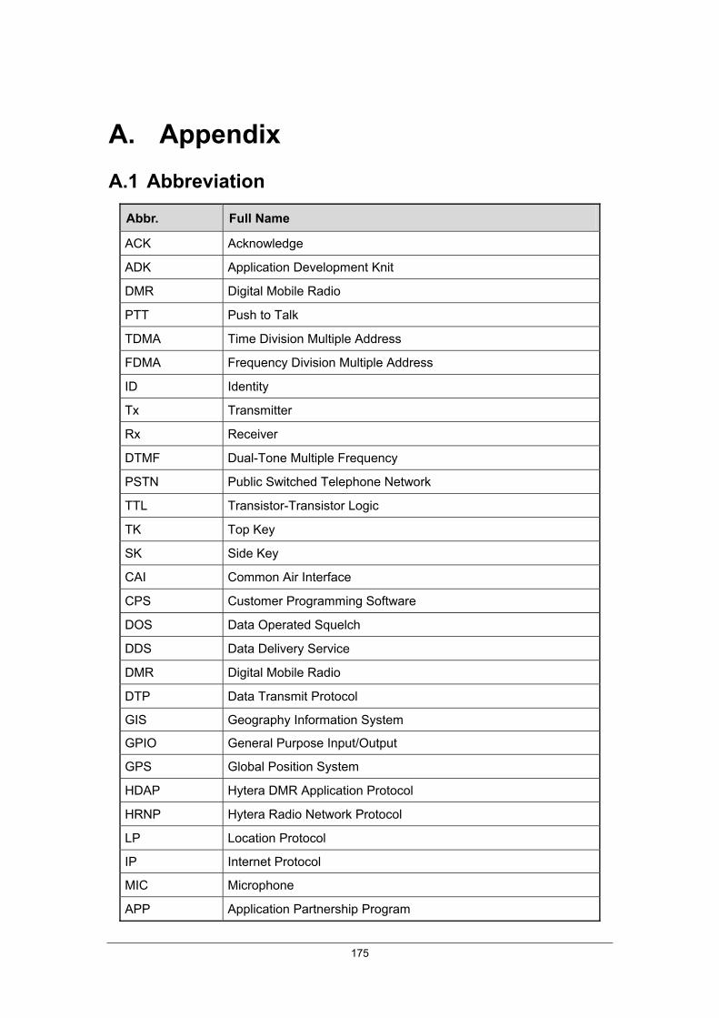
175
A. Appendix A.1 Abbreviation
Abbr. Full Name
ACK Acknowledge
ADK Application Development Knit
DMR Digital Mobile Radio
PTT Push to Talk
TDMA Time Division Multiple Address
FDMA Frequency Division Multiple Address
ID Identity
Tx Transmitter
Rx Receiver
DTMF Dual-Tone Multiple Frequency
PSTN Public Switched Telephone Network
TTL Transistor-Transistor Logic
TK Top Key
SK Side Key
CAI Common Air Interface
CPS Customer Programming Software
DOS Data Operated Squelch
DDS Data Delivery Service
DMR Digital Mobile Radio
DTP Data Transmit Protocol
GIS Geography Information System
GPIO General Purpose Input/Output
GPS Global Position System
HDAP Hytera DMR Application Protocol
HRNP Hytera Radio Network Protocol
LP Location Protocol
IP Internet Protocol
MIC Microphone
APP Application Partnership Program

Hytera DMR System Planner
176
Abbr. Full Name
PC Personal Computer
RCP Radio Control Protocol
RNDIS Remote Network Driver Interface Specification
RRS Radio Registration Service
RTP Real-time Transport Protocol
TP Telemetry Protocol
TMP Text Message Protocol
UART Universal Asynchronous Receiver/Transmitter
UDP User Datagram Protocol
USB Universal Serial Bus
A.2 Hytera Official Website
You can make an order or obtain product information by visiting our official website at: http://www.hytera.com, or contacting your dealer.

