dmrb volume 4 section 2 part 4 - standards for · pdf filehd 43/04 drainage data management...
TRANSCRIPT

November 2004
DESIGN MANUAL FOR ROADS AND BRIDGES
VOLUME 4 GEOTECHNICS ANDDRAINAGE
SECTION 2 DRAINAGE
PART 4
HD 43/04
DRAINAGE DATA MANAGEMENTSYSTEM FOR HIGHWAYS
SUMMARY
This document provides best practice guidance for therecording of physical data associated with drainageassets.
INSTRUCTIONS FOR USE
This is a new document to be inserted into the manual.
1. Remove Contents page for Volume 4.
2. Insert new Contents page for Volume 4 datedNovember 2004.
3. Insert HD 43/04 into Volume 4, Section 2.
4. Please archive this sheet as appropriate.
Note: A quarterly index with a full set of VolumeContents Pages is available separately from TheStationery Office Ltd.

HD 43/04
Drainage Data ManagementSystem for Highways
Summary: This document provides best practice guidance for the recording of physical dataassociated with drainage assets.
DESIGN MANUAL FOR ROADS AND BRIDGES
THE HIGHWAYS AGENCY
SCOTTISH EXECUTIVE
WELSH ASSEMBLY GOVERNMENTLLYWODRAETH CYNULLIAD CYMRU
THE DEPARTMENT FOR REGIONAL DEVELOPMENTNORTHERN IRELAND

Volume 4 Section 2Part 4 HD 43/04
November 2004
REGISTRATION OF AMENDMENTS
Amend Page No Signature & Date of Amend Page No Signature & Date ofNo incorporation of No incorporation of
amendments amendments
Registration of Amendments

Volume 4 Section 2Part 4 HD 43/04
November 2004
REGISTRATION OF AMENDMENTS
Amend Page No Signature & Date of Amend Page No Signature & Date ofNo incorporation of No incorporation of
amendments amendments
Registration of Amendments

VOLUME 4 GEOTECHNICS ANDDRAINAGE
SECTION 2 DRAINAGE
PART 4
HD 43/04
DRAINAGE DATA MANAGEMENTSYSTEM FOR HIGHWAYS
Contents
Chapter
1. Introduction
2. Data Collection
3. Inventory
4. General Drainage Records
5. Drainage Records for Point Items
6. Drainage Records for Continuous Items
7. Drainage Records for Region Items
8. Referencing Drainage Items
9. References and Bibliography
10. Enquiries
Appendix A: Line Types and Symbology
Appendix B: Tables
Appendix C: Referencing Details
Appendix D: Survey Inspection Sheets for Point Items
Appendix E: Survey Inspection Sheets for ContinuousItems
Appendix F: Survey Inspection Sheets for Region Items
DESIGN MANUAL FOR ROADS AND BRIDGES
November 2004

Volume 4 Section 2Part 4 HD 43/04
November 2004 1/1
Chapter 1Introduction
1. INTRODUCTION
General
1.1 It is essential to have accurate data on the locationand condition of highway drainage assets in order to planordered and cost effective maintenance. Data gatheredshould be stored in a manner that permits quick and easyaccess and in a format that is readily understandable tothe Managing Agents and Operating Companies (MAs)and the Overseeing Organisations irrespective of the datasource.
1.2 This Standard defines the data to be collected andthe way it should be recorded. Data storage software isnot specified, but a Geographical Information System(GIS) should be used. The Highways Agency willprovide a GIS to ensure national uniformity within itsnetwork.
Scope
1.3 This Standard applies to all surveys and schemeson motorways and other trunk roads.
Mandatory Sections
1.4 Boxed text indicates sections that the MAsshall comply with or shall have agreed a suitabledeparture from this Standard with the relevantOverseeing Organisation. The remainder of thedocument contains advice and guidance which iscommended to all Overseeing Organisations, MAsand other Highway Authorities.
Implementation with Existing Schemes
1.5 This Standard should be used forthwith for all newmanagement contracts for England for the inspection andmaintenance of drainage data. Whilst the generalprinciples of the advice and guidance contained in thisdocumnet are endorsed, this Standard is not mandatoryfor use in Scotland, Wales or Northern Ireland, andreference as to correct procedural aspects should bemade to the respective Overseeing Organisation’smaintenance instructions and manuals.

Volume 4 Section 2Part 4 HD 43/04
November 2004 2/1
Chapter 2Data Collection
2. DATA COLLECTION
General
2.1 Information relating to highway drainage items canbe obtained from a number of sources and in a variety offormats.
2.2 The Managing Agents (MAs) and OperatingCompanies are responsible for collating drainagedata from all available sources and also selectingwhich data are to be included within the HighwaysAgency Dranage Data Management System(HADDMS).
2.3 Where existing information currently held withinthe Routine Maintenance Management System (RMMS)databases are considered for transfer into HADDMS, theaccuracy of such information, and also the suitability ofthe data set for conversion, should be carefully checkedprior to making a decision.
Closed Circuit Television Survey
2.4 CCTV survey is a means of obtaining data on thecondition of enclosed drainage systems, by the insertionof a camera into the drain and recording the imageelectronically.
2.5 SD15, Model Contract Documents for the CCTVSurvey of Highway Drainage Systems (MCHW 5.9.1)contains requirements on the data to be recorded and therecording format.

Volume 4 Section 2Part 4 HD 43/04
Chapter 3Inventory
3. INVENTORY
General
3.1 This Chapter identifies drainage inventory itemtypes. A definition or description of each inventory itemis provided.
3.2 The symbols to be used for displayinghighway drainage assets within a HADDMS areshown in Appendix A.
Item Types
3.3 The inventory items described below have beengrouped as either ‘Point’, ‘Continuous’ or ‘Region’items.
3.4 For consistency, the definitions used in thedrainage inventory of the RMMS Manual have beenadopted and identified within this Standard.
Definitions for Point Items
Manhole
3.5 A chamber constructed to give access to a drain,sewer or other underground service (RMMS).
Piped Grip
3.6 A piped conduit across the verge of a road to leadsurface water away from the carriageway (RMMS).
Outfall
3.7 The point where one drainage system dischargesto a watercourse.
Inlet/Outlet
3.8 An inlet is the point where a watercourse, ditch,swale or pond discharges into another system. An outletis a point where a system discharges into a pond orchannel.
Gully
3.9 A chamber at the side of the road connected to adrainage system to receive surface water and to trap
degra
3.1sed
Ca
3.1thema
Int
3.1drpit
3.1whwafor
So
3.1wisooffil
Bi
3.1
Pu
3.1fro
3.1usma
Ro
3.1thedetec
November 2004
bris. The chamber is usually surmounted by a surfaceting (RMMS).
0 A gully may incorporate a sump to retainiment.
tchpit
1 A pit in a drainage system whose base lies below level of the outgoing invert. It prevents silt or solidterial from moving downstream (RMMS).
erceptor
2 A structure placed where surface water enters theainage system with a similar function to that of a catch (RMMS).
3 A petrol and oil interceptor is a gravity separator,ich uses the difference between the specific gravity ofter and fuel/oil to trap the latter. These items are am of pollution control.
akaway
4 This may be an underground pit, usually filledth large aggregate, or a chamber that enables water toak into the ground. A soakaway may also be a length porous pipeline with a granular surround or rubbleled trench (Exfiltration ditch).
furcation or Storm Overflow
5 Chamber with two or more outgoing pipes.
mping Station
6 An installation which pumps water under pressurem one point to another through a rising main.
7 A pumping station will include a number of valves,ually between the station and the rising main, whichy be in a separate chamber.
dding Eye
8 Rodding eyes provide access at surface level for clearance, in one direction only, of obstructions and
bris using normally accepted manual roddinghniques.
3/1

Volume 4 Section 2Part 4 HD 43/04
Chapter 3Inventory
Ghost Manhole
3.19 Ghost manholes are a database representationused to identify the location of bends within continuousitems or the positions of junctions where no manholesexist.
Definitions for Continuous Sub-surface Items
3.20 The following definitions are for continuousdrainage items which generally transfer flow belowground.
Pipework
3.21 A pipeline normally conveys surface water runoffwithin closed pipework.
Rising Main
3.22 A sealed pipeline through which water is pumpedunder pressure.
Culvert
3.23 An enclosed conduit, usually a large pipe forconveying a watercourse or ditch drain, below thecarriageway or adjacent ground (RMMS).
Land Drainage
3.24 Pipework installed for the purpose of removinggroundwater.
Syphon (inverted)
3.25 A section of pipeline, more often a culvert, that isdepressed below the adjacent pipeline levels for thepurpose of transferring flows beneath an obstruction,usually the carriageway.
Definitions for Continuous Surface Channel Items
3.26 The following definitions are for continuousdrainage items which generally transfer flow aboveground (along the surface of the item).
3.27 Drawings of continuous channel types are shownin Series F of the Highway Construction Details (HCDMCHW 3) and RMMS.
Surface Water Channel
3.28 A narrow channel, generally located near the edgeof the carriageway, constructed to carry and lead awaysurface water (RMMS).
3/2
Edge Channel
3.29 A channel formed where the surface of thecarriageway meets the kerb.
Drainage Channel Block
3.30 A precast concrete unit. The HighwayConstruction Details, Section 1: Series B - Edge ofPavement Details, (MHCW 3) show six shapes ofchannel block.
Grip
3.31 A shallow trench, located across the verge of aroad, to lead surface water away from the carriageway(RMMS).
Swales and Grassed Channels
3.32 Swales are wide shallow grassed channelsnormally located adjacent to carriageways but oftenseparated by a section of verge.
3.33 Grass channels are of similar dimensions toconventional concrete channels, are generally narrowerthan swales and are located at the edge of the pavement.
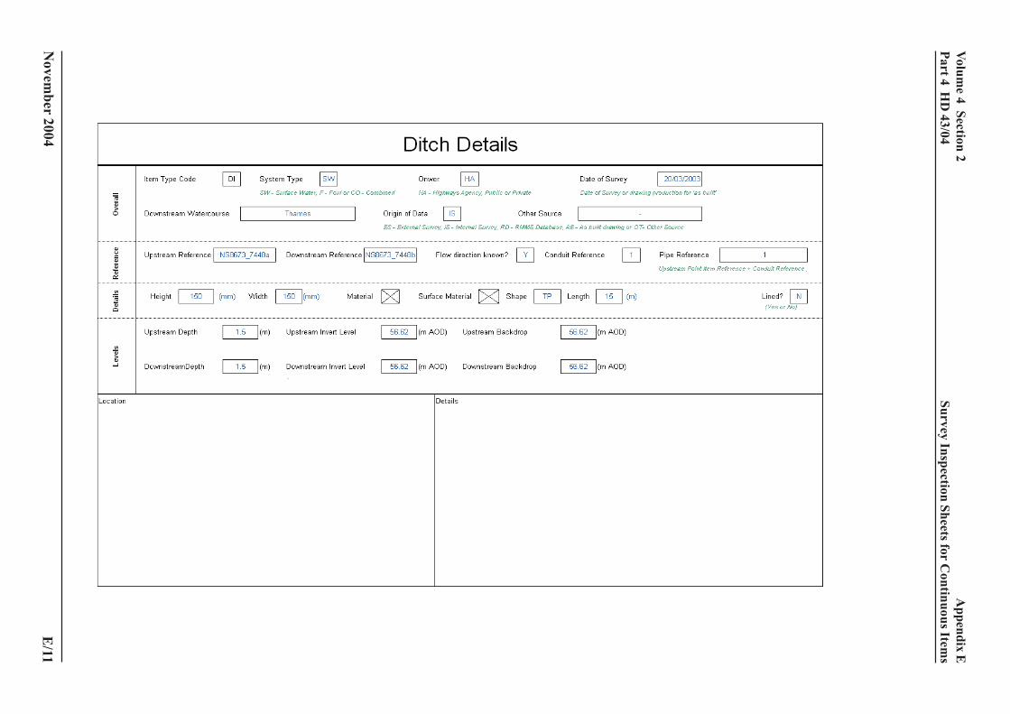
Ditch
3.34 A trench, generally parallel to the carriageway.This may be lined (RMMS).
Region Connector
3.35 A Region Connector should only be used toidentify connectivity between regional items and adjacentpoint items.
Definitions for Continuous Surface and Sub-surfaceChannels and Drain Items
3.36 The following definitions are for continuousdrainage items which generally transfer flow both aboveand below ground.
Combined Pipe and Channel Drain
3.37 A surface water channel combined with a drainageconduit below it, all cast in one. The channel isconnected hydraulically to the conduit via gratings orintermittent slots.
November 2004

Volume 4 Section 2Part 4 HD 43/04
Chapter 3Inventory
Linear Drainage Channel
3.38 A closed profile hydraulic conduit with slotslocated in and above the conduit.
3.39 A U-shaped channel that usually has a separategrating or, in some instances, an integral grating.
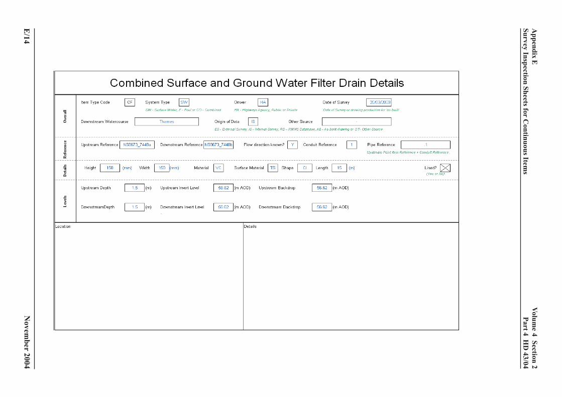
Combined Surface and Ground Water Filter Drains
3.40 Also known as French Drains, these comprise aperforated or porous carrier pipe surrounded by beddingmaterial within a trench filled with filter material. Thesurface of the drain may be topped with a range ofmaterials or exposed filter material. The system drainsboth surface and sub surface water.
Fin Drain
3.41 A planar geo-composite arrangement designed toremove sub surface moisture from beneath thepavement. This may solely comprise a core surroundedby textile, refer to Type 5 in drawing F18 (HCD), orincorporate a pipe within the geotextile wrap, refer toType 6 in drawing F18 (HCD).
Narrow Filter Drain
3.42 An edge of pavement subsurface drain thatcomprises filter material and a carrier pipe, which may bewrapped in a geotextile, refer to Type 8 and Type 9 indrawing F15 (HCD).
Combined Kerb Drain
3.43 Monolithic kerb-drains have an internal drainagechannel within the pre-cast concrete or metal kerb unit.
Filter Drain
3.44 A field drain, usually running parallel and adjacentto a carriageway, surrounded by granular material suchas gravel, within which may be laid porous or perforatedpipe (RMMS).
Informal Drain
3.45 Also known as ‘Over the edge drainage,’ wheresurface water flows off the carriageway and across theverge to a drainage system, usually a ditch.
Counterfort Drain
3.46 A drain, other than a filter drain running parallel toa carriageway, surrounded by granular material such asgravel. Includes herringbone and intercepting drains(RMMS).
D
3.incawbe
D
3.fohi
3.ex
R
3.peinpege
Se
3.w
In
3.wfisu
P
3.upwshto
W
3.bysureof
November 2004
efinitions for Region Items
47 Balancing ponds are featured within the RMMSventory. All ponds should be identified as one of thetegories specified in the following paragraphs. MAsill be responsible for ensuring that pond items haveen correctly classified.
etention Pond
48 A detention pond temporarily stores run-offllowing heavy rainfall and discharges it later fromghway drainage systems to a different system.
49 A detention pond is designed to be dry fortended periods.
etention Pond
50 A retention pond allows water to be held for longriods. It may allow for the controlled release of water, some instances water is allowed to seep intormeable banks or gravel. A retention pond willnerally retain some water at all times.
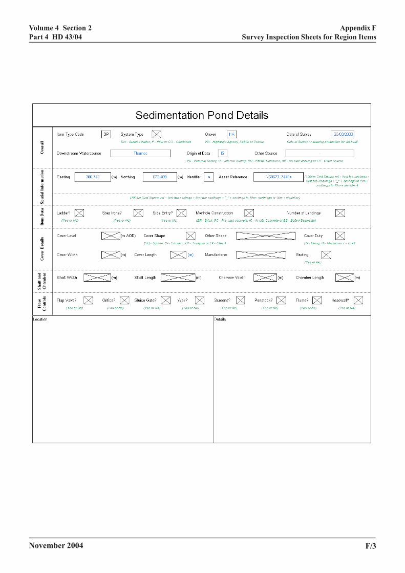
dimentation Pond
51 Sedimentation ponds provide some degree ofater treatment by allowing sediment to settle out.
filtration Basins
52 Infiltration basins are designed to retain stormater flows and allow the water to percolate through alter layer which may typically comprise porous material,ch as gravel.
ollution Containment Pond/Tank
53 This is a device or an area located immediatelystream of the outlet from a drainage system to a
atercourse. Having a minimum volume of 20m3 itould incorporate a shut off mechanism. Its purpose is contain spillages of potentially polluting liquids.
etlands
54 Wetlands are areas that are permanently saturated surface water or groundwater. They are able topport aquatic and/or semi-aquatic vegetation such ased swamps, marshes, or bogs, depending on the degree saturation and inundation.
3/3

Volume 4 Section 2Part 4 HD 43/04
ORDS
Chapter 4General Drainage Records
4. GENERAL DRAINAGE REC
General
4.1 This section identifies the attributes to be recordedfor all inventory items.
4.2 The following details shall be gathered for allitem types.
Origin of Data and Other Source
4.3 The source of data records shall be identifiedwithin the Origin of Data field. This will enablefuture users to associate a level of confidence withdata. Table B1 of Appendix B lists codes whichdescribe the source of data.
4.4 The Other Source field shall be populated incases where data has been obtained from othervalidated sources.
4.5 Where more than one data source is available themore reliable source should be used.
4.6 As-Built drawings are prepared immediately afterconstruction is complete.
4.7 Drainage data featured within record plans shouldalso be identified as an As-Built drawing origin type ifMAs can confirm that the information illustrated withinthe drawings is current and accurate.
Date
4.8 The Date field should contain the date of survey/inspection and not when the data was entered within aGIS.
Item Reference
4.9 All items shall have a unique reference.Further details regarding the production ofreferences are given in Chapter 8.
It
4.B4
Sy
O
D
4.w
4.exthwto
4.wWimwrivsh
November 2004
em Type
4.10 A two character code shall be attributed to allitems to classify the item type.
11 Item type codes are shown in Tables B2, B3 and of Appendix B.
stem Type
4.12 Any items which convey domestic orindustrial wastewater shall be identified as a ‘foulsewerage system’ within the System Type field.
wner
4.13 Owners of known public or private drainswhich contribute to the drainage network shall beidentified within the Ownership field.
ownstream Watercourse
14 Drainage networks will eventually discharge into aatercourse or will permeate into the ground.
15 Drainage items may permeate into the ground viafiltration ditches, swales or soakaways. In these cases,e Downstream Watercourse field should be populatedith the point reference of the item which enables flow percolate into the ground.
16 All items which eventually discharge toatercourses should contain the Downstreamatercourse field populated with the name of the mostmediate downstream watercourse. In cases where
atercourses are unnamed (i.e. a tributary of a mainer) then the nearest named downstream watercourseould be used.
4/1
Volume 4 Section 2Part 4 HD 43/04
POINT ITEMS
Chapter 5Drainage Records for Point Items
5. DRAINAGE RECORDS FOR
General
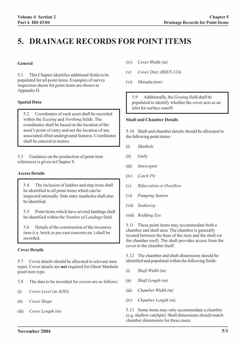
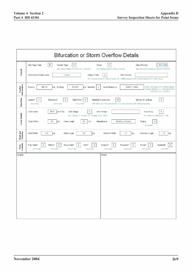
5.1 This Chapter identifies additional fields to bepopulated for all point items. Examples of surveyinspection sheets for point items are shown inAppendix D.
Spatial Data
5.2 Coordinates of each asset shall be recordedwithin the Easting and Northing fields. Thecoordinates shall be based on the location of theasset’s point of entry and not the location of anyassociated offset underground features. Coordinatesshall be entered in metres.
5.3 Guidance on the production of point itemreferences is given in Chapter 8.
Access Details
5.4 The inclusion of ladders and step irons shallbe identified to all point items which can beinspected internally. Side entry manholes shall alsobe identified.
5.5 Point items which have several landings shallbe identified within the Number of Landings field.
5.6 Details of the construction of the inventoryitem (i.e. brick or pre-cast concrete etc.) shall berecorded.
Cover Details
5.7 Cover details should be allocated to relevant itemtypes. Cover details are not required for Ghost Manholepoint item type.
5.8 The data to be recorded for covers are as follows:
(i) Cover Level (m AOD)
(ii) Cover Shape
(iii) Cover Length (m)
(iv
(v)
(vi
Sh
5.1the
(i)
(ii)
(iii
(iv
(v)
(vi
(vi
(vi
5.1chloctheco
5.1ide
(i)
(ii)
(iii
(iv
5.1(e.ch
November 2004
) Cover Width (m)
Cover Duty (BSEN 124)
) Manufacturer.
5.9 Additionally, the Grating field shall bepopulated to identify whether the cover acts as aninlet for surface runoff.
aft and Chamber Details
0 Shaft and chamber details should be allocated to following point items:
Manhole
Gully
) Interceptor
) Catch Pit
Bifurcation or Overflow
) Pumping Station
i) Soakaway
ii) Rodding Eye.
1 These point items may accommodate both aamber and shaft area. The chamber is generallyated between the base of the item and the shaft (or chamber roof). The shaft provides access from the
ver to the chamber itself.
2 The chamber and shaft dimensions should bentified and populated within the following fields:
Shaft Width (m)
Shaft Length (m)
) Chamber Width (m)
) Chamber Length (m).
3 Some items may only accommodate a chamberg. shallow catchpit). Shaft dimensions should matchamber dimensions for these cases.
5/1

Volume 4 Section 2Part 4 HD 43/04
Chapter 5Drainage Records for Point Items
Flow Controls
5.14 Several types of flow control exist within thedrainage network. The following flow controls should beidentified:
(i) Orifice
(ii) Flap Valve
(iii) Sluice Gate
(iv) Weir
(v) Screen or Grill
(vi) Penstock
(vii) Flume
(viii) Headwall
(ix) Hydro-Dynamic Flow Control Device.
5.15 The existence of flow controls within a pointitem shall be identified.
Ghost Nodes at Ponds
5.16 Ghost nodes should be applied to represent thecentroid of regional item. The ghost nodes should bepopulated with the fields identified within Section 4(General Data Records).
November 20045/2

Volume 4 Section 2Part 4 HD 43/04
Chapter 6Drainage Records for Continuous Items
OR CONTINUOUS ITEMS
6. DRAINAGE RECORDS FGeneral
6.1 This Chapter identifies attributes to be recordedfor all continuous items. Examples of survey inspectionsheets for continuous items are shown in Appendix E.
6.2 All continuous inventory items shall have aunique reference.
6.3 Guidance on the referencing of continuous items isstated in Chapter 8.
6.4 Both upstream and downstream references ofpoint items shall be recorded to ensure connectivityand flow direction to relevant point items.
6.5 If the flow direction for a continuous item isunknown then this should be identified within the Flowdirection known field.
Physical Details
6.6 All continuous elements shall have the Shapefield populated. Standard shapes for above andbelow ground items are shown in Table B5 and B6of Appendix B.
6.7 The Material field should be populated for thefollowing continuous items:
(i) All Channels
(ii) Combined Pipe and Channel Drain
(iii) Combined Kerb and Drainage
(iv) Culvert
(v) Land Drain
(vi) Pipework
(vii) Syphon.
November 2004
6.8 Material codes to be used within the Material fieldare listed in Table B7 of Appendix B.
6.9 The Material field should be the material of theconveyance element and not of filter material.
6.10 Surface materials shall be identified for allchannels.
6.11 The Surface Material field should be populatedfor the following continuous items:
(i) Combined Pipe and Channel Drain
(ii) Linear Drainage Channel
(iii) Combined Surface and Ground Water FilterDrain
(iv) Fin Drain
(v) Narrow Filter Drain
(vi) Filter drain.
6.12 Channels with continuous access covers should beidentified within the Surface Material field.
Item Dimensions and Levels
6.13 The following fields should be populated for allcontinuous items types.
(i) Width (mm)
(ii) Height - excluding circular shaped items (mm)
(iii) Length (m)
(iv) Upstream Depth (m)
(v) Upstream Invert Level (m AOD)
(vi) Downstream Depth (m)
(vii) Downstream Invert Level (m AOD).
6/1

Volume 4 Section 2Part 4 HD 43/04
Chapter 6Drainage Records for Continuous Items
6.14 All invert levels shall be in metres aboveOrdnance Datum.
Lined or Unlined
6.15 The following continuous items may be lined:
(i) Ditches
(ii) Grips
(iii) Pipework.
Region Connector
6.16 A Region Connector (defined in Section 3.35)should be populated with fields stated in Section 4(General Drainage Records) only.
November 20046/2

Volume 4 Section 2Part 4 HD 43/04
November 2004
Chapter 7Drainage Records for Region Items
7. DRAINAGE RECORDS FOR REGION ITEMS
7/1
General
7.1 This Chapter identifies additional fields to bepopulated for all region items. Examples of surveyinspection sheets for point items are shown inAppendix F.
Spatial Data
7.2 The Easting and Northing fields shall bepopulated with coordinates of the centre of a regionitem.
7.3 Guidance on the production of item references isgiven in Chapter 8.
Connectivity
7.4 Table A2 in Appendix A shows the graphical regionstyle for ponds. A ghost node should also be digitised atthe centroid of all regional items.
7.5 A Region Connector should be used to connectghost nodes allocated at the centroid of regions, toupstream and downstream point items.

Volume 4 Section 2Part 4 HD 43/04
Chapter 8Referencing Drainage Items
GE ITEMS
8. REFERENCING DRAINAGeneral
8.1 A referencing system provides the key to theaccumulation of additional information. All items withinthe inventory require a unique reference.
8.2 The item referencing convention contained in thisStandard is based on the item’s relative position to theOrdnance Survey National Grid.
References for point and region items are always 12characters in length. References for continuous items are13 characters in length.
8.3 The reference system describes the location of adrainage asset to the nearest 10m Ordnance Survey gridsquare. The final character within the reference of pointand region items is a unique alphanumeric character.
8.4 An asset’s reference should be used as a guide toits approximate location. Actual location of the asset isstored within the Easting and Northing fields (see section5.2 for further details).
8.5 Allocation of new references to drainage assetsshould be managed by MAs. References allocated duringsurveys by sub contractors are to be validated by MAs.
Reference System for Point and Region Items
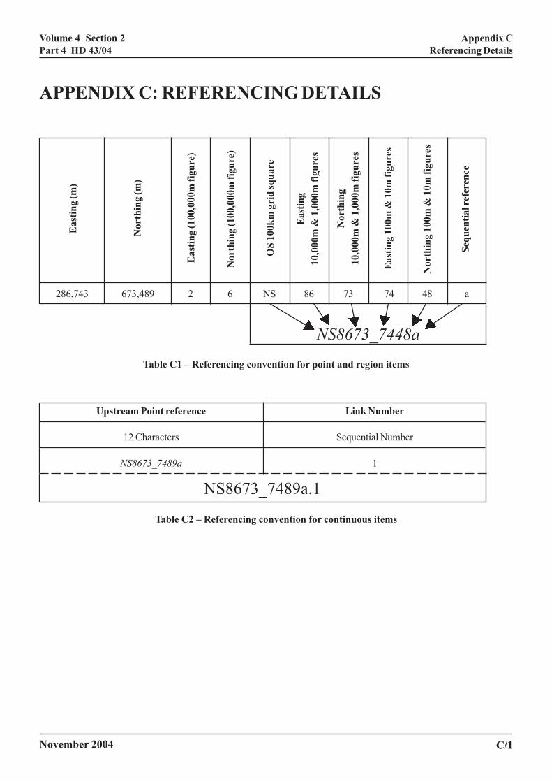
8.6 An example of how to produce a drainagereference for a point item from Eastings and Northingsvalues is shown in Table C1, Appendix C.
8.7 The first two characters of the reference refer tothe asset’s location to the nearest Ordnance Survey100 km grid square (see Table C3 and Figure C1 inAppendix C).
8.8 The first four digits of the reference relate to theitem’s location within 10,000m and 1,000m OrdnanceSurvey grid squares. This is followed by an underscoreand four more digits which refer to the item’s locationwithin 1,000m and 100m Ordnance Survey grid squares.
8.9 The following single arbitrary character should beassigned to all items located within 10m OrdnanceSurvey grid squares as an alphanumeric letter.
November 2004
Reference System for Link Items
8.10 All continuous items should also have uniquereference identifiers.
Link references are composed of the upstream pointreference and a sequentially numbered reference(example shown in Table C2 of Appendix C).
Reference System for Region Items
8.11 The reference of a region should be based on theestimated coordinates of the centre of a region.
8/1

Volume 4 Section 2Part 4 HD 43/04
November 2004
9. REFERENCES AND BIBLIOGRAPHY
Chapter 9References and Bibliography
9/1
1. Trunk Road Maintenance Manual (TRMM).The Stationery Office, London
2. Routine Maintenance Management SystemManual (RMMS). The Stationery Office,London
3. Manual of Contract Documents for HighwayWorks (MCHW). The Stationery Office, London
Volume 3: Highway Construction Details(HCD) (MHCW 3)
Volume 5: Contract Documents for SpecialistActivities (MCHW 5) SD 15. “Documents forthe CCTV Survey of Highway DrainageSystems”. (MCDHW 5.9).
Series 9000 - Specification. (MCDHW 5.9.2).
Series NG 9000 - Notes for Guidance.(MCDHW 5.9.3).
4. Design Manual for Road and Bridges (DMRB).The Stationery Office, London

Volume 4 Section 2Part 4 HD 43/04
November 2004 10/1
10. ENQUIRIES
All technical enquiries or comments on this Standard should be sent in writing as appropriate to:
Chief Highway EngineerThe Highways Agency123 Buckingham Palace RoadLondon G CLARKESW1W 9HA Chief Highway Engineer
Chief Road EngineerScottish ExecutiveVictoria QuayEdinburgh J HOWISONEH6 6QQ Chief Road Engineer
Chief Highway EngineerTransport DirectorateWelsh Assembly GovernmentLlywodraeth Cynulliad CymruCrown Buildings M J A PARKERCardiff Chief Highway EngineerCF10 3NQ Transport Directorate
Director of EngineeringThe Department for Regional DevelopmentRoads ServiceClarence Court10-18 Adelaide Street G W ALLISTERBelfast BT2 8GB Director of Engineering
Chapter 10Enquiries

Volume 4 Section 2Part 4 HD 43/04
November 2004
APPENDIX A: LINE TYPES AND SYMBOLOGY
Type Line type
Sub Surface Continuous Items (i.e. Pipework)
Surface Continuous Items (i.e. Surface Water Channel)
Combined Surface and Sub Surface Items (i.e. Combined Surface andGround Water Filter Drains)
Table A1 – Line types for Continuous Items
Type Symbol
Manhole
Outfall
Pumping Station
Bifurcation or Overflow
Gully
Piped Grip
Soakaway
Interceptor
Catch Pit
Ghost Node
All Ponds and Wetlands
Table A2 – Symbols for Point and Region Items
A/1
Appendix ALine Types and Symbology
Volume 4 Section 2Part 4 HD 43/04
November 2004
APPENDIX B: TABLES
B/1
Appendix BTables
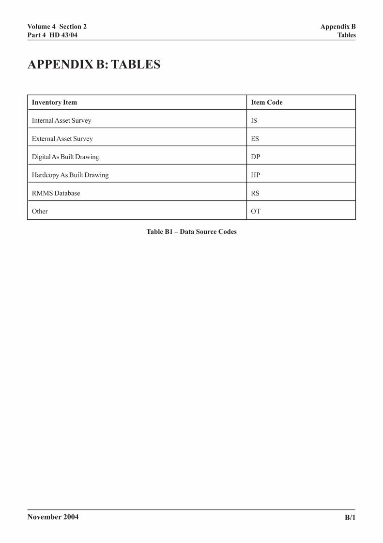
Inventory Item Item Code
Internal Asset Survey IS
External Asset Survey ES
Digital As Built Drawing DP
Hardcopy As Built Drawing HP
RMMS Database RS
Other OT
Table B1 – Data Source Codes

Volume 4 Section 2Part 4 HD 43/04
November 2004
Inventory Item Item Code
Manhole MH
Piped Grip PG
Outfall OU
Inlet IT
Gully GU
Catchpit CP
Interceptor IN
Soakaway SO
Bifurcation or Storm Overflow BI
Pumping Station PS
Rodding Eye RE
Ghost Manhole GN
Table B2 – Codes for Point Items
Inventory Item Item Code
Detention Pond DP
Retention Pond RP
Sediment Pond SP
Infiltration Basin IB
Pollution Containment Pond/Tank PC
Wetlands WL
Table B3 – Codes for Region Inventory Items
B/2
Appendix BTables
Volume 4 Section 2Part 4 HD 43/04
November 2004
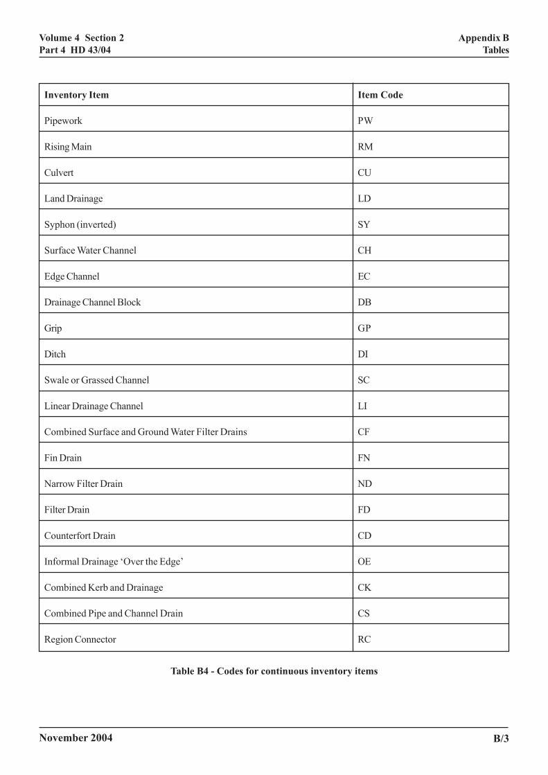
Inventory Item Item Code
Pipework PW
Rising Main RM
Culvert CU
Land Drainage LD
Syphon (inverted) SY
Surface Water Channel CH
Edge Channel EC
Drainage Channel Block DB
Grip GP
Ditch DI
Swale or Grassed Channel SC
Linear Drainage Channel LI
Combined Surface and Ground Water Filter Drains CF
Fin Drain FN
Narrow Filter Drain ND
Filter Drain FD
Counterfort Drain CD
Informal Drainage ‘Over the Edge’ OE
Combined Kerb and Drainage CK
Combined Pipe and Channel Drain CS
Region Connector RC
Table B4 - Codes for continuous inventory items
B/3
Appendix BTables

Volume 4 Section 2Part 4 HD 43/04
November 2004
Inventory Item Item Code
Circular CI
Rectangular RE
Egg EG
Oval OV
Arch AC
Other OT
Table B5 – Shape codes for below ground continuous inventory items
Inventory Item Item Code
Triangular TG
Rectangular RE
Trapezoidal TP
U Shaped US
Table B6 – Shape codes for above ground continuous inventory items
Inventory Item Item Code
Vitrified Clay VC
Concrete CO
MDPE MD
PVC PV
HPPE HE
Cast Iron CI
Asbestos Cement AC
Pitch Fibre PF
Table B7 – Material codes for continuous inventory items
B/4
Appendix BTables

Volume 4 Section 2Part 4 HD 43/04
November 2004
Inventory Item Item Code
Granular GR
Turf TU
Pre-coated Chips CC
Tar Spray TS
Bitumen Bonded Shredded Tyres BB
Removable Bars RB
Continuous Gratings CG
System Type Item Code
Foul FW
Storm SW
Table B8 – Surface material codes for continuous inventory items
Table B9 – System type codes
B/5
Appendix BTables
Volume 4 Section 2Part 4 HD 43/04
November 2004
286,743 673,489 2 6 NS 86 73 74 48 a
East
ing
(m)
Nor
thin
g (m
)
East
ing
(100
,000
m fi
gure
)
Nor
thin
g (1
00,0
00m
figu
re)
OS
100k
m g
rid
squa
re
East
ing
10,0
00m
& 1
,000
m fi
gure
s
Nor
thin
g10
,000
m &
1,0
00m
figu
res
Eas
ting
100m
& 1
0m fi
gure
s
Nor
thin
g 10
0m &
10m
figu
res
Sequ
entia
l ref
eren
ce
NS8673_7448a
Table C1 – Referencing convention for point and region items
Upstream Point reference Link Number
12 Characters Sequential Number
NS8673_7489a 1
NS8673_7489a.1
Table C2 – Referencing convention for continuous items
C/1
Appendix CReferencing Details
APPENDIX C: REFERENCING DETAILS

Volume 4 Section 2Part 4 HD 43/04
November 2004
OS Suffix Minimum Maximum Minimum MaximumEasting (m) Easting (m) Northing (m) Northing (m)
NA 0 100,000 9000,000 1,000,000
NF 0 100,000 800,000 900,000
NL 0 100,000 700,000 800,000
NQ 0 100,000 600,000 700,000
NV 0 100,000 500,000 600,000
SA 0 100,000 400,000 500,000
SF 0 100,000 300,000 400,000
SL 0 100,000 200,000 300,000
SQ 0 100,000 100,000 200,000
SV 0 100,000 0 100,000
HW 0 100,000 1,000,000 1,100,000
NB 100,000 200,000 900,000 1,000,000
NG 100,000 200,000 800,000 900,000
NM 100,000 200,000 700,000 800,000
NR 100,000 200,000 600,000 700,000
NW 100,000 200,000 500,000 600,000
SB 100,000 200,000 400,000 500,000
SG 100,000 200,000 300,000 400,000
SM 100,000 200,000 200,000 300,000
SR 100,000 200,000 100,000 200,000
SW 100,000 200,000 0 100,000
HX 200,000 300,000 1,000,000 1,100,000
NC 200,000 300,000 900,000 1,000,000
NH 200,000 300,000 800,000 900,000
NN 200,000 300,000 700,000 800,000
NS 200,000 300,000 600,000 700,000
NX 200,000 300,000 500,000 600,000
SC 200,000 300,000 400,000 500,000
SH 200,000 300,000 300,000 400,000
SN 200,000 300,000 200,000 300,000
SS 200,000 300,000 100,000 200,000
SX 200,000 300,000 0 100,000
C/2
Appendix CReferencing Details

Volume 4 Section 2Part 4 HD 43/04
November 2004
OS Suffix Minimum Maximum Minimum MaximumEasting (m) Easting (m) Northing (m) Northing (m)
HY 300,000 400,000 1,000,000 1,100,000
ND 300,000 400,000 900,000 1,000,000
NJ 300,000 400,000 800,000 900,000
NO 300,000 400,000 700,000 800,000
NT 300,000 400,000 600,000 700,000
NY 300,000 400,000 500,000 600,000
SD 300,000 400,000 400,000 500,000
SJ 300,000 400,000 300,000 400,000
SO 300,000 400,000 200,000 300,000
ST 300,000 400,000 100,000 200,000
SY 300,000 400,000 0 100,000
NE 400,000 500,000 900,000 1,000,000
NK 400,000 500,000 800,000 900,000
NP 400,000 500,000 700,000 800,000
NU 400,000 500,000 600,000 700,000
NZ 400,000 500,000 500,000 600,000
SE 400,000 500,000 400,000 500,000
SK 400,000 500,000 300,000 400,000
SP 400,000 500,000 200,000 300,000
SU 400,000 500,000 100,000 200,000
SZ 400,000 500,000 0 100,000
TA 500,000 600,000 400,000 500,000
TF 500,000 600,000 300,000 400,000
TL 500,000 600,000 200,000 300,000
TQ 500,000 600,000 100,000 200,000
TV 500,000 600,000 0 100,000
TG 600,000 700,000 300,000 400,000
TM 600,000 700,000 200,000 300,000
TR 600,000 700,000 100,000 200,000
Table C3 – Boundary coordinates for Ordnance Survey 100km grid squares
C/3
Appendix CReferencing Details

Volume 4 Section 2Part 4 HD 43/04
November 2004
Figure C1 – Ordnance survey 100km grid square references
C/4
Appendix CReferencing Details

Volume 4 Section 2Part 4 HD 43/04
November 2004
APPENDIX D: SURVEY INSPECTION SHEETS FORPOINT ITEMS
D/1
Appendix DSurvey Inspection Sheets for Point Items

Volume 4 Section 2Part 4 HD 43/04
November 2004D/2
Appendix DSurvey Inspection Sheets for Point Items

Volume 4 Section 2Part 4 HD 43/04
November 2004 D/3
Appendix DSurvey Inspection Sheets for Point Items

Volume 4 Section 2Part 4 HD 43/04
November 2004D/4
Appendix DSurvey Inspection Sheets for Point Items

Volume 4 Section 2Part 4 HD 43/04
November 2004 D/5
Appendix DSurvey Inspection Sheets for Point Items

Volume 4 Section 2Part 4 HD 43/04
November 2004D/6
Appendix DSurvey Inspection Sheets for Point Items

Volume 4 Section 2Part 4 HD 43/04
November 2004 D/7
Appendix DSurvey Inspection Sheets for Point Items

Volume 4 Section 2Part 4 HD 43/04
November 2004D/8
Appendix DSurvey Inspection Sheets for Point Items
Volume 4 Section 2Part 4 HD 43/04
November 2004 D/9
Appendix DSurvey Inspection Sheets for Point Items

Volume 4 Section 2Part 4 HD 43/04
November 2004D/10
Appendix DSurvey Inspection Sheets for Point Items

Volume 4 Section 2Part 4 HD 43/04
November 2004 D/11
Appendix DSurvey Inspection Sheets for Point Items

Volume 4 Section 2Part 4 HD 43/04
November 2004D/12
Appendix DSurvey Inspection Sheets for Point Items

Volume 4 Section 2
Part 4 HD
43/04
Novem
ber 2004
APPEN
DIX
E: SUR
VEY
INSPEC
TION
SHEETS FO
RC
ON
TINU
OU
S ITEMS
E/1
Appendix E
Survey Inspection Sheets for Continuous Item
s

Volume 4 Section 2
Part 4 HD
43/04
Novem
ber 2004E
/2
Appendix E
Survey Inspection Sheets for Continuous Item
s

Volume 4 Section 2
Part 4 HD
43/04
Novem
ber 2004E
/3
Appendix E
Survey Inspection Sheets for Continuous Item
s

Volume 4 Section 2
Part 4 HD
43/04
Novem
ber 2004E
/4
Appendix E
Survey Inspection Sheets for Continuous Item
s

Volume 4 Section 2
Part 4 HD
43/04
Novem
ber 2004E
/5
Appendix E
Survey Inspection Sheets for Continuous Item
s

Volume 4 Section 2
Part 4 HD
43/04
Novem
ber 2004E
/6
Appendix E
Survey Inspection Sheets for Continuous Item
s

Volume 4 Section 2
Part 4 HD
43/04
Novem
ber 2004E
/7
Appendix E
Survey Inspection Sheets for Continuous Item
s

Volume 4 Section 2
Part 4 HD
43/04
Novem
ber 2004E
/8
Appendix E
Survey Inspection Sheets for Continuous Item
s

Volume 4 Section 2
Part 4 HD
43/04
Novem
ber 2004E
/9
Appendix E
Survey Inspection Sheets for Continuous Item
s

Volume 4 Section 2
Part 4 HD
43/04
Novem
ber 2004E
/10
Appendix E
Survey Inspection Sheets for Continuous Item
s
Volume 4 Section 2
Part 4 HD
43/04
Novem
ber 2004E
/11
Appendix E
Survey Inspection Sheets for Continuous Item
s

Volume 4 Section 2
Part 4 HD
43/04
Novem
ber 2004E
/12
Appendix E
Survey Inspection Sheets for Continuous Item
s
v

Volume 4 Section 2
Part 4 HD
43/04
Novem
ber 2004E
/13
Appendix E
Survey Inspection Sheets for Continuous Item
s
Volume 4 Section 2
Part 4 HD
43/04
Novem
ber 2004E
/14
Appendix E
Survey Inspection Sheets for Continuous Item
s

Volume 4 Section 2
Part 4 HD
43/04
Novem
ber 2004E
/15
Appendix E
Survey Inspection Sheets for Continuous Item
s

Volume 4 Section 2
Part 4 HD
43/04
Novem
ber 2004E
/16
Appendix E
Survey Inspection Sheets for Continuous Item
s

Volume 4 Section 2
Part 4 HD
43/04
Novem
ber 2004E
/17
Appendix E
Survey Inspection Sheets for Continuous Item
s

Volume 4 Section 2
Part 4 HD
43/04
Novem
ber 2004E
/18
Appendix E
Survey Inspection Sheets for Continuous Item
s

Volume 4 Section 2
Part 4 HD
43/04
Novem
ber 2004E
/19
Appendix E
Survey Inspection Sheets for Continuous Item
s

Volume 4 Section 2
Part 4 HD
43/04
Novem
ber 2004E
/20
Appendix E
Survey Inspection Sheets for Continuous Item
s

Volume 4 Section 2
Part 4 HD
43/04
Novem
ber 2004E
/21
Appendix E
Survey Inspection Sheets for Continuous Item
s

Volume 4 Section 2Part 4 HD 43/04
November 2004
APPENDIX F: SURVEY INSPECTION SHEETS FORREGION ITEMS
F/1
Appendix FSurvey Inspection Sheets for Region Items

Volume 4 Section 2Part 4 HD 43/04
November 2004
Appendix FSurvey Inspection Sheets for Region Items
F/2
Volume 4 Section 2Part 4 HD 43/04
November 2004 F/3
Appendix FSurvey Inspection Sheets for Region Items

Volume 4 Section 2Part 4 HD 43/04
November 2004
Appendix FSurvey Inspection Sheets for Region Items
F/4

Volume 4 Section 2Part 4 HD 43/04
November 2004 F/5
Appendix FSurvey Inspection Sheets for Region Items

Volume 4 Section 2Part 4 HD 43/04
November 2004
Appendix FSurvey Inspection Sheets for Region Items
F/6