dn 25 - 300, pn 63 - 160 -...
TRANSCRIPT
FlowProTM
High Performance ValveDN 25 - 300, PN 63 - 160
2
ApplicationControl of neutral and aggressive ga-ses, vapours and liquids in industrysuch as air, water, steam, gas oil, etc.
Flow in piping systems are controlled,mixed, distri-buted or shut off usinga pneumatic SCHMIDT actuator, anelectric linear actuator, a SCHMIDTthrust unit and electric rotary actuatorin conjunction with the valve.
Due to its simple design and adapta-billity to different plant systems, thevalve has a wide range of appli-cation.
Product features
Body shape for optimumflow characteristics
• favourable flow dynamics when cor-rectly selected
• solid top or top and bottom guidedplug
Long service life and ope-rational reliability
• with aggressive or evaporating me-dia due to sturdy design
• strong guides, thus minimal vibrati-ons and wear
Replaceable trim
• simple maintenance since the valvebody can remain in the piping whentrim is replaced
• seat screwed
Wide range of application
• up to 8 kvs values are available persize
• trims are partially exchangeable
Quality assurance system certifica-ted acc. ISO 9001/EN 29001.
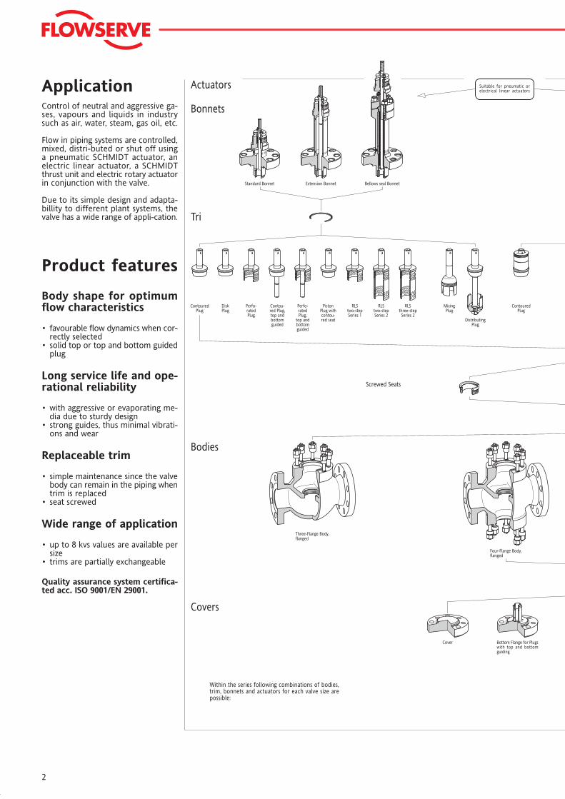
Actuators
Bonnets
Tri
Bodies
Covers
Within the series following combinations of bodies,trim, bonnets and actuators for each valve size arepossible:
Cover Bottom Flange for Plugswith top and bottomguiding
Four-Flange Body,flanged
Three-Flange Body,flanged
Screwed Seats
ContouredPlug
DiskPlug
Perfo-ratedPlug
Contou-red Plug,top andbottomguided
Perfo-ratedPlug,
top andbottomguided
PistonPlug withcontou-red seat
RLStwo-stepSeries 1
RLStwo-stepSeries 2
RLSthree-stepSeries 2
MixingPlug
DistributingPlug
ContouredPlug
Standard Bonnet Extension Bonnet Bellows seal Bonnet
Suitable for pneumatic orelectrical linear actuators
3
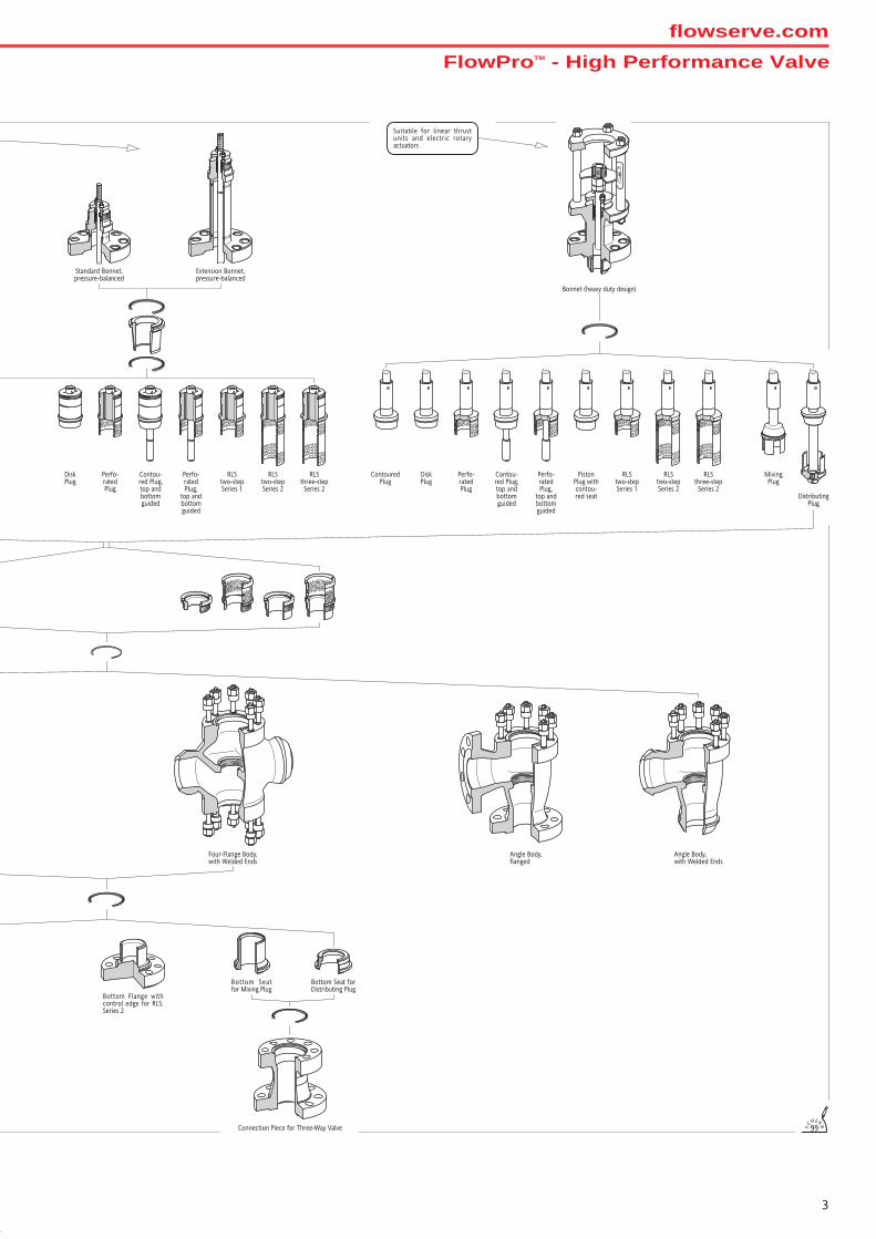
Standard Bonnet,pressure-balanced
Extension Bonnet,pressure-balanced
100
0
Bonnet (heavy duty design)
Bottom Flange withcontrol edge for RLS,Series 2
Bottom Seatfor Mixing Plug
Bottom Seat forDistributing Plug
Connection Piece for Three-Way Valve
Four-Flange Body,with Welded Ends
Angle Body,flanged
Angle Body,with Welded Ends
ContouredPlug
DiskPlug
Perfo-ratedPlug
Contou-red Plug,top andbottomguided
Perfo-ratedPlug,
top andbottomguided
PistonPlug withcontou-red seat
RLStwo-stepSeries 1
RLStwo-stepSeries 2
RLSthree-stepSeries 2
MixingPlug
DistributingPlug
DiskPlug
Perfo-ratedPlug
Contou-red Plug,top andbottomguided
Perfo-ratedPlug,
top andbottomguided
RLSthree-stepSeries 2
99S
CHERR
Suitable for linear thrustunits and electric rotaryactuators
RLStwo-stepSeries 1
RLStwo-stepSeries 2
FlowProTM - High Performance Valveflowserve.com
4
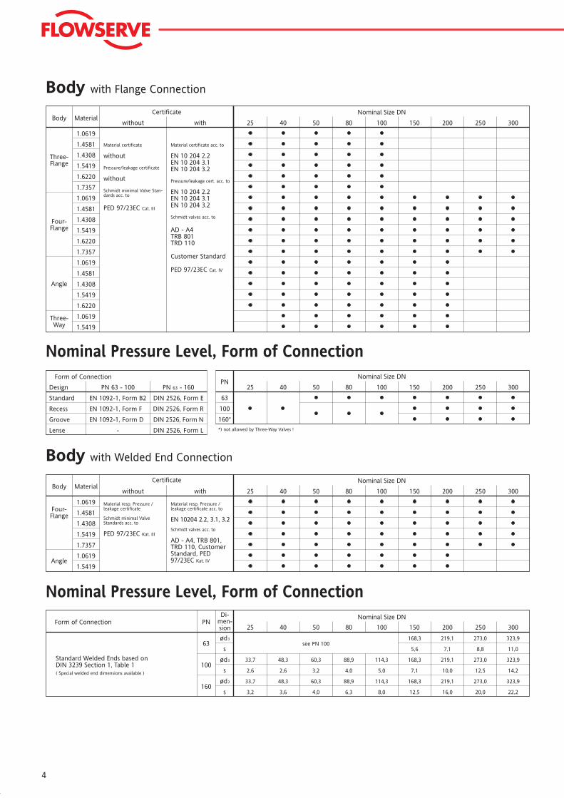
Nominal Pressure Level, Form of Connection
Body with Flange Connection
Nominal Pressure Level, Form of Connection
Body with Welded End Connection
Nominal Size DN
Standard Welded Ends based onDIN 3239 Section 1, Table 1( Special welded end dimensions available )
Form of Connection PN
63ød
Di-men-sion
s
3
33,7 48,3 60,3 88,9 114,3
168,3 219,1 273,0 323,9
2,6 2,6 3,2 4,0 5,0
5,6 7,1 8,8 11,0
25 40 50 80 100 150 200 250 300
168,3 219,1 273,0 323,9
7,1 10,0 12,5 14,2
33,7 48,3 60,3 88,9 114,3
3,2 3,6 4,0 6,3 8,0
168,3 219,1 273,0 323,9
12,5 16,0 20,0 22,2
ød
s
ød
s
100
160
3
3
see PN 100
Nominal Size DNPN
63
100
160*
25 40 50 80 100 150 200 250 300
*) not allowed by Three-Way Valves !
Form of Connection
EN 1092-1, Form B2 DIN 2526, Form EStandard
Recess
Groove
Lense
EN 1092-1, Form F DIN 2526, Form R
EN 1092-1, Form D DIN 2526, Form N
DIN 2526, Form L
Design PN 63 - 100 PN 63 - 160
-
25 40 50 80 100 150 200 250 300
Nominal Size DNBody
Four-Flange
Angle
Material resp. Pressure /leakage certificate
Schmidt minimal ValveStandards acc. to
PED 97/23EC Kat. III
Material resp. Pressure /leakage certificate acc. to
EN 10204 2.2, 3.1, 3.2
Schmidt valves acc. to
AD - A4, TRB 801,TRD 110, CustomerStandard, PED97/23EC Kat. IV
Certificate
without withMaterial
1.0619
1.5419
1.7357
1.0619
1.5419
1.4308
1.4581
Body25 40 50 80 100 150 200 250 300
Nominal Size DN
Four-Flange
Angle
Three-Flange
Three-Way
Certificate
without with
Material certificate
without
Pressure/leakage certificate
without
Schmidt minimal Valve Stan-dards acc. to
PED 97/23EC Cat. III
Material certificate acc. to
EN 10 204 2.2EN 10 204 3.1EN 10 204 3.2
Pressure/leakage cert. acc. to
EN 10 204 2.2EN 10 204 3.1EN 10 204 3.2
Schmidt valves acc. to
AD - A4TRB 801TRD 110
Customer Standard
PED 97/23EC Cat. IV
Material
1.0619
1.4581
1.5419
1.7357
1.0619
1.6220
1.0619
1.4581
1.5419
1.7357
1.0619
1.4581
1.5419
1.4308
1.6220
1.4308
1.6220
1.4308
1.5419
5
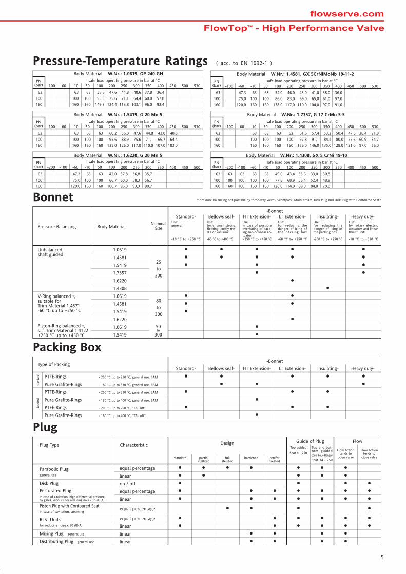
Bonnet
Packing Box
Plug
Pressure-Temperature Ratings ( acc. to EN 1092-1 )
1) pressure balancing not possible by three-way valves, Silentpack, MultiStream, Disk Plug and Disk Plug with Contoured Seat !
Body MaterialPressure Balancing
1.0619
1.4581
1.5419
1.7357
Unbalanced,shaft guided
V-Ring balanced 1),suitable forTrim Material 1.4571-60 °C up to +250 °C
NominalSize
80
to
300
25
to
300
50to
300
-BonnetHeavy duty-
Use:by rotary electricactuators and linearthrust units
-10 °C to +530 °C
Insulating-Use:for reducing thedanger of icing ofthe packing box
-200 °C to +250 °C
LT Extension-Use:for reducing thedanger of icing ofthe packing box
-60 °C to +250 °C
HT Extension-Use:in case of possibleoverhating of pack-ing and/or linear ac-tuator>250 °C to +450 °C
Bellows seal-Use:toxic, smell strong,fleeting, costly me-dia or vacuum
-60 °C to +400 °C
Standard-Use:general
-10 °C to +250 °C
Piston-Ring balanced 1),s. f. Trim Material 1.4122+250 °C up to +450 °C
1.6220
1.4308
1.6220
1.0619
1.4581
1.5419
1.0619
1.5419
Type of Packing
PTFE-Rings - 200 °C up to 250 °C, general use, BAM
Pure Grafite-Rings - 180 °C up to 530 °C, general use, BAMstan
dard
load
ed
PTFE-Rings - 200 °C up to 250 °C, general use, BAM
Pure Grafite-Rings - 180 °C up to 400 °C, general use, BAM
-Bonnet
Heavy duty-Insulating-LT Extension-HT Extension-Bellows seal-Standard-
PTFE-Rings - 200 °C up to 250 °C, “TA-Luft”
Pure Grafite-Rings - 180 °C up to 400 °C, “TA-Luft”
Design Guide of Plug Flow
on / off
equal percentage
linear
standard partialstellited
fullstellited
hardened tenifertreated
Top guided
Seat 4 - 250
Top and bot-tom guided(only Four-Flange)
Seat 34 - 250
Flow Actiontends to
open valve
Flow Actiontends to
close valve
CharacteristicPlug Type
Parabolic Pluggeneral use
Disk Plug
Perforated Plugin case of cavitation, high differential pressureby gases, vapours, for reducing nois ≤ 15 dB(A)
Piston Plug with Contoured Seatin case of cavitation, steaming
RLS -Unitsfor reducing noise ≤ 20 dB(A)
equal percentage
linear
equal percentage
equal percentage
linear
linearMixing Plug general use
linearDistributing Plug general use
Body Material W.Nr.: 1.0619, GP 240 GH
PN(bar)
safe load operating pressure in bar at °C
63
100
160
-100 -60 -10 50 100 200 250 300 350 400 450 500 530
58,8
93,3
149,3
63
100
160
63
100
160
47,6
75,6
124,4
44,8
71,1
113,8
40,6
64,4
103,1
37,8
60,0
96,0
36,4
57,8
92,4
Body Material W.Nr.: 1.6220, G 20 Mn 5
PN(bar)
safe load operating pressure in bar at °C
63
100
160
-100 -60 -10 350 400 50050-200 100
47,3
75,0
120,0
200 250 300 450
42,0
66,7
106,7
63
100
160
63
100
160
37,8
60,0
96,0
36,8
58,3
93,3
35,7
56,7
90,7
Body Material W.Nr.: 1.5419, G 20 Mo 5
PN(bar)
safe load operating pressure in bar at °C
63
100
160
-100 -60 -10 50 100 200 250 300 350 400 450 500 530
63
100
160
63
100
160
63
100
160
60,2
95,6
135,0
56,0
88,9
126,0
47,6
75,6
117,0
44,8
71,1
110,0
42,0
66,7
107,0
40,6
64,4
103,0
Body Material W.Nr.: 1.4308, GX 5 CrNi 19-10
PN(bar)
safe load operating pressure in bar at °C
63
100
160
-100 -60 -10 350 400 50050-200 100 200 250 300 450
49,0
77,8
128,0
63
100
160
63
100
160
63
100
160
63
100
160
43,4
68,9
114,0
35,6
56,4
89,0
33,0
52,4
84,0
30,8
48,9
78,0
Body Material W.Nr.: 1.7357, G 17 CrMo 5-5
PN(bar)
safe load operating pressure in bar at °C
63
100
160
-100 -60 -10 50 100 200 250 300 350 400 450 500 530
63
100
160
63
100
160
63
100
160
63
100
160
61,6
97,8
156,0
57,4
91,1
146,0
53,2
84,4
135,0
50,4
80,0
128,0
47,6
75,6
121,0
38,4
60,9
97,0
21,8
34,7
56,0
Body Material W.Nr.: 1.4581, GX 5CrNiMoNb 19-11-2
PN(bar)
safe load operating pressure in bar at °C
63
100
160
-100 -60 -10 50 100 200 250 300 350 400 450 500 530
47,3
75,0
120,0
63
100
160
63
100
160
54,0
86,0
138,0
46,0
83,0
117,0
43,0
69,0
110,0
38,0
61,0
97,0
41,0
65,0
104,0
36,0
57,0
91,0
FlowTopTM - High Performance Valveflowserve.com
6
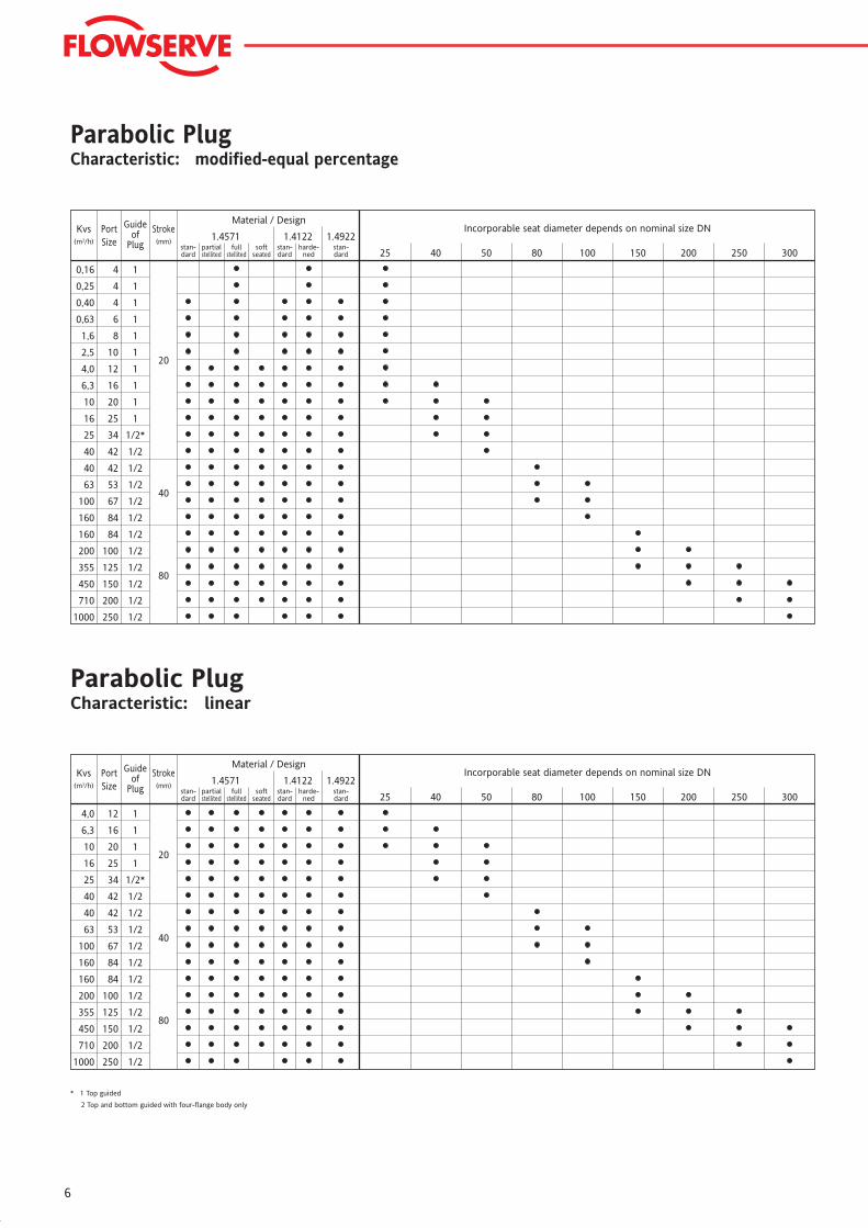
* 1 Top guided
2 Top and bottom guided with four-flange body only
Parabolic PlugCharacteristic: modified-equal percentage
Parabolic PlugCharacteristic: linear
Incorporable seat diameter depends on nominal size DNMaterial / Design
1.4571 1.4922
25 40 50 80 100 150 200 250 300
1.4122Kvs
(m3/h)
1000
710
450
355
200
160
160
100
63
40
25
16
10
6,3
4,0
40
PortSize
250
200
150
125
100
84
84
67
53
42
34
25
20
16
12
42
Guideof
Plug
1/2
1/2
1/2
1/2
1/2
1/2
1/2
1/2
1/2
1/2
1/2*
1
1
1
1
1/2
Stroke(mm)
20
40
80
stan-dard
partialstellited
fullstellited
stan-dard
harde-ned
stan-dard
softseated
Incorporable seat diameter depends on nominal size DNMaterial / Design
1.4571 1.4922
25 40 50 80 100 150 200 250 300
1.4122Kvs
(m3/h)
1000
710
450
355
200
160
160
100
63
40
25
16
10
6,3
4,0
2,5
1,6
0,63
0,25
0,16
40
0,40
PortSize
250
200
150
125
100
84
84
67
53
42
34
25
20
16
12
10
8
6
4
4
42
4
Guideof
Plug
1/2
1/2
1/2
1/2
1/2
1/2
1/2
1/2
1/2
1/2
1/2*
1
1
1
1
1
1
1
1
1
1/2
1
Stroke(mm)
20
40
80
stan-dard
partialstellited
fullstellited
stan-dard
harde-ned
stan-dard
softseated
7
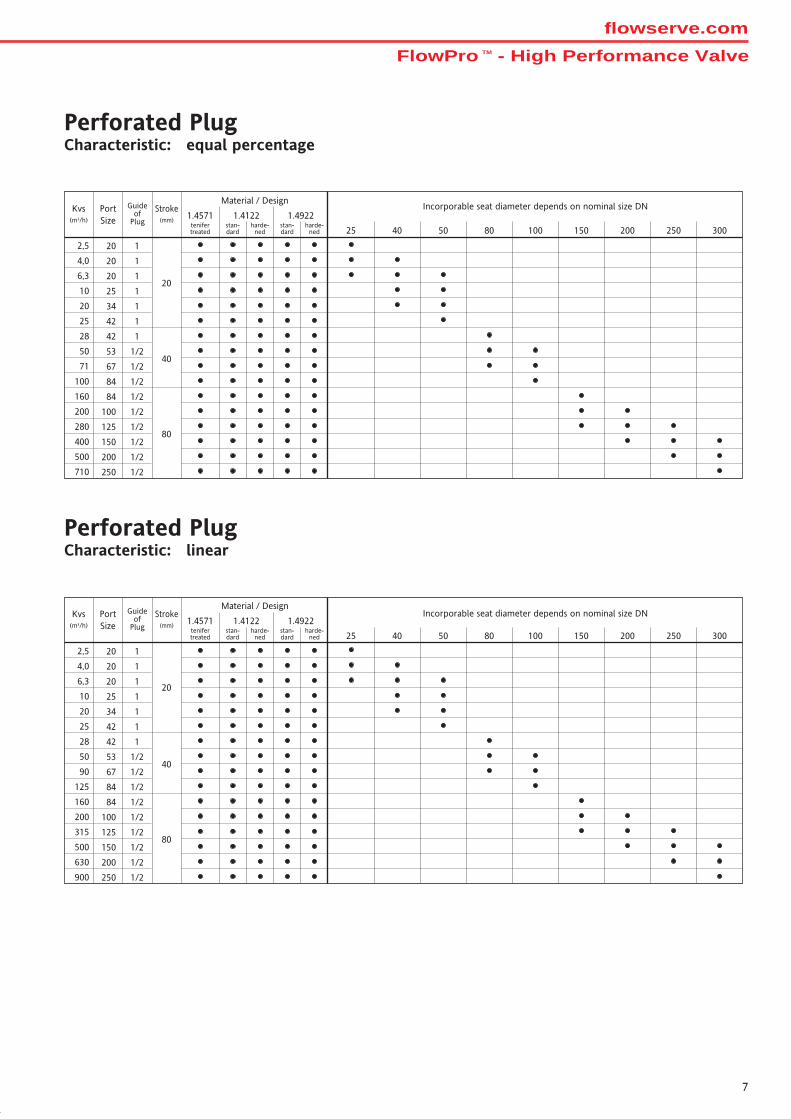
Perforated PlugCharacteristic: linear
Perforated PlugCharacteristic: equal percentage
Incorporable seat diameter depends on nominal size DNMaterial / Design
1.4122 1.4922PortSize
Guideof
Plug
Stroke(mm)
20
25 40 50 80 100 150 200 250 300
40
80
Kvs(m3/h)
710
4
2
1
5
1
2
5
7
0
0
0
6
0
8
0
1
0
0
0
0
0
0
25
6
2
1
,
0
0
3
28
250
200
150
125
100
84
84
67
53
42
34
25
20
42
1/2
1/2
1/2
1/2
1/2
1/2
1/2
1/2
1/2
1
1
1
1
1
1.4571
4,0 20 1
2,5 20 1
stan-dard
harde-ned
tenifertreated
stan-dard
harde-ned
Incorporable seat diameter depends on nominal size DNMaterial / Design
1.4122 1.4922PortSize
Guideof
Plug
Stroke(mm)
20
25 40 50 80 100 150 200 250 300
40
80
Kvs(m3/h)
900
5
2
1
6
1
3
5
9
2
0
1
0
3
6
0
0
0
5
0
5
0
0
25
1
2
0
0
28
250
200
150
125
100
84
84
67
53
42
34
25
42
1/2
1/2
1/2
1/2
1/2
1/2
1/2
1/2
1/2
1
1
1
1
1.4571
6,3 20 1
4,0 20 1
2,5 20 1
stan-dard
harde-ned
tenifertreated
stan-dard
harde-ned
FlowPro TM - High Performance Valveflowserve.com
8
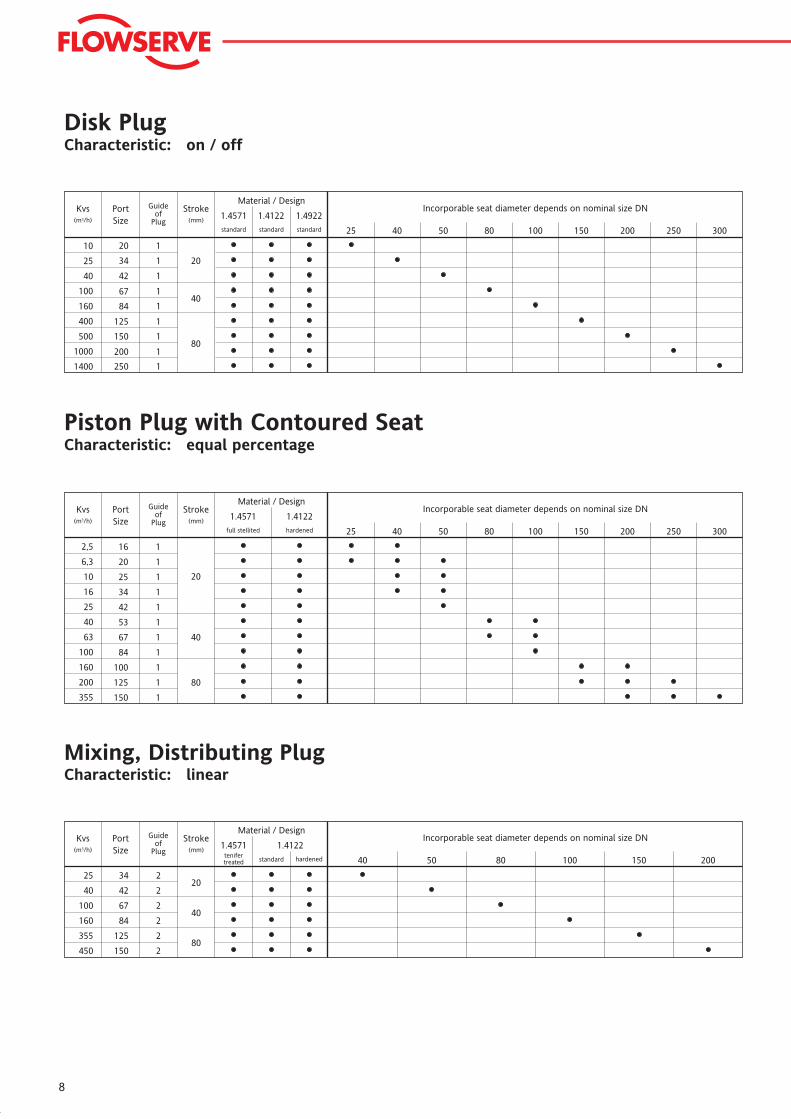
Mixing, Distributing PlugCharacteristic: linear
Disk PlugCharacteristic: on / off
Piston Plug with Contoured SeatCharacteristic: equal percentage
Incorporable seat diameter depends on nominal size DNMaterial / Design
1.4122PortSize
Guideof
Plug
Stroke(mm)
20
2
2
2
2
2
2
40
80150
125
84
67
42
34
450
355
160
100
40
25
Kvs(m3/h)
40 50 80 100 150 200standard
1.4571tenifertreated hardened
Incorporable seat diameter depends on nominal size DNMaterial / Design
1.4571 1.4922PortSize
Guideof
Plug
Stroke(mm)
20
1
1
1
1
1
1
1
1
1
25 40 50 80 100 150 200 250 300
1.4122Kvs
(m3/h)
1400
1000
500
400
160
100
40
25
10
40
80200
150
125
84
67
42
34
20
250
standard standard standard
Incorporable seat diameter depends on nominal size DNMaterial / Design
1.4571 1.4122PortSize
Guideof
Plug
Stroke(mm)
20
25 40 50 80 100 150 200 250 300
40
80
Kvs(m3/h)
1
1
1
150
125
100
84
67
53
42
34
25
20
16
355
200
160
100
63
25
16
10
6,3
40
1
1
1
1
1
1
1
1
2,5
full stellited hardened
9
1.4
1.5
4.1
1.2
1.3
1.1
1.3
2.5
2.1
2.2
2.3
2.4
1.2
3.1
3.5
1.5
3.2
1.4
3.3
3.4
3.6
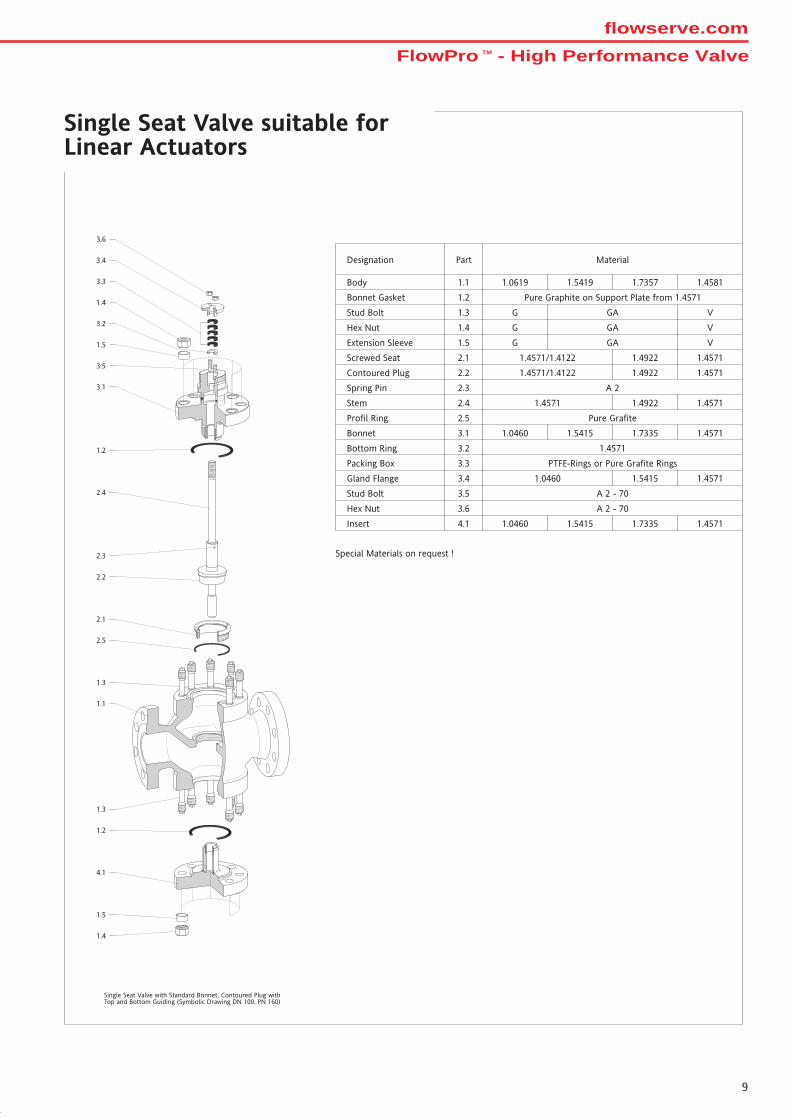
Single Seat Valve suitable forLinear Actuators
Single Seat Valve with Standard Bonnet, Contoured Plug withTop and Bottom Guiding (Symbolic Drawing DN 100, PN 160)
Body
Designation MaterialPart
Bonnet Gasket
Stud Bolt
Hex Nut
Extension Sleeve
Screwed Seat
Contoured Plug
Spring Pin
Stem
Profil Ring
Bonnet
Bottom Ring
Packing Box
Gland Flange
Stud Bolt
Hex Nut
Insert
1.0619 1.5419 1.7357 1.4581
Pure Graphite on Support Plate from 1.4571
V
1.4922 1.4571
A 2
1.4571 1.4922 1.4571
Pure Grafite
1.0460 1.5415 1.7335 1.4571
1.4571
PTFE-Rings or Pure Grafite Rings
1.0460 1.5415 1.4571
A 2 - 70
A 2 - 70
1.0460 1.5415 1.7335 1.4571
V
V
1.4571/1.4122
1.4571/1.4122 1.4922 1.4571
Special Materials on request !
1.1
1.2
1.3
1.4
1.5
2.1
2.2
2.3
2.4
2.5
3.1
3.2
3.3
3.4
3.5
3.6
4.1
G
G
G
GA
GA
GA
FlowPro TM - High Performance Valveflowserve.com
10
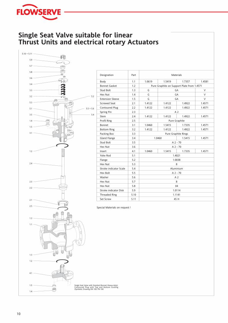
Single Seat Valve suitable for linearThrust Units and electrical rotary Actuators
100
0
1.4
1.5
4.1
1.2
1.3
1.1
1.3
2.5
2.1
2.2
2.3
2.4
1.2
3.1
1.5
1.4
3.5
5.1
5.3
3.2
3.3
3.4
3.6
5.8
5.7
5.9
5.10 + 5.11
5.4
5.5 + 5.6
5.2
Single Seat Valve with Standard Bonnet (heavy-duty),Contoured Plug with Top and Bottom Guiding(Symbolic Drawing DN 100, PN 160
Body
Designation MaterialsPart
1.1
Bonnet Gasket 1.2
Stud Bolt 1.3
Hex Nut 1.4
Extension Sleeve 1.5
Screwed Seat 2.1
Contoured Plug 2.2
Spring Pin 2.3
Stem 2.4
Profil Ring 2.5
Bonnet 3.1
Bottom Ring 3.2
Packing Box 3.3
Gland Flange 3.4
Stud Bolt 3.5
Hex Nut 3.6
Insert 4.1
1.0619 1.5419 1.7357 1.4581
Pure Graphite on Support Plate from 1.4571
G GA V
1.4922 1.4571
A 2
1.4122 1.4922 1.4571
Pure Graphite
1.0460 1.5415 1.7335 1.4571
Pure Graphite Rings
1.0460 1.5415 1.4571
A 2 - 70
A 2 - 70
1.0460 1.5415 1.7335 1.4571
G GA V
G GA V
1.4122
1.4922 1.45711.4122
5.1
5.2
5.3
5.4
5.5
5.6
5.7
5.8
5.9
5.10
5.11
Yoke Rod
Flange
Hex Nut
Stroke indicator Scale
Hex Bolt
Washer
Hex Nut
Hex Nut
Stroke indicator Disk
Threaded Ring
Set Screw
1.4021
1.0038
8
Aluminium
A 2 - 70
A 2
8
04
1.0114
1.1141
45 H
1.4922 1.45711.4122
Special Materials on request !
1.4122
1.4122
1.4122
1.4122
11
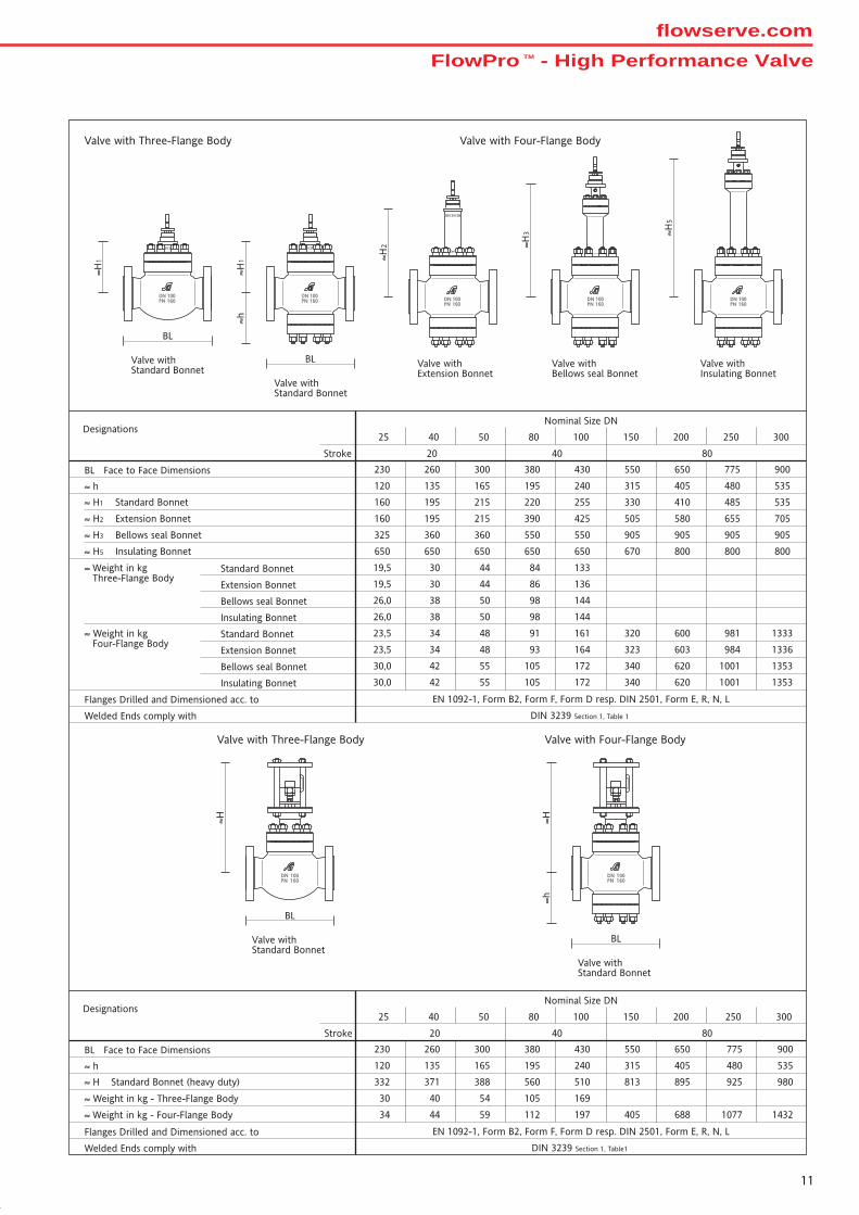
Valve with Three-Flange Body Valve with Four-Flange Body
Valve withStandard Bonnet
≈H1
BL
DN 100PN 160
Valve withExtension Bonnet
≈H2
DN 100PN 160
Valve withStandard Bonnet
≈H1
BL
≈h
DN 100PN 160
Valve withBellows seal Bonnet
≈H3
DN 100PN 160
Valve withInsulating Bonnet
≈H5
DN 100PN 160
Nominal Size DN
BL Face to Face Dimensions
Stroke
Welded Ends comply with
≈ h
40 80
≈ H Standard Bonnet (heavy duty)
DIN 3239 Section 1, Table1
≈ Weight in kg - Three-Flange Body
Flanges Drilled and Dimensioned acc. to
Designations
≈ Weight in kg - Four-Flange Body
25
230
120
332
30
34
20
40
260
135
371
40
44
50
300
165
388
54
59
80
380
195
560
105
112
100
430
240
510
169
197
150
550
315
813
405
200
650
405
895
688
250
775
480
925
1077
300
900
535
980
1432
EN 1092-1, Form B2, Form F, Form D resp. DIN 2501, Form E, R, N, L
Valve withStandard Bonnet
BL
≈h≈H
DN 100PN 160
100
0
Valve withStandard Bonnet
BL
100
0
DN 100PN 160
≈H
Valve with Three-Flange Body Valve with Four-Flange Body
Nominal Size DN
BL Face to Face Dimensions
Stroke
Welded Ends comply with
≈ h
40 80
≈ H1 Standard Bonnet
DIN 3239 Section 1, Table 1
≈ Weight in kgThree-Flange Body
Flanges Drilled and Dimensioned acc. to
Standard Bonnet
Extension Bonnet
Designations
≈ H2 Extension Bonnet
≈ Weight in kgFour-Flange Body
Standard Bonnet
Extension Bonnet
≈ H3 Bellows seal Bonnet
Bellows seal Bonnet
Bellows seal Bonnet
19,5
19,5
23,5
23,5
20
30
30
34
34
44
44
48
48
84
86
91
93
133
136
161
164
320
323
600
603
981
984
1333
1336
26,0
30,0
38
42
50
55
98
105
144
172 340 620 1001 1353
≈ H5 Insulating Bonnet
Insulating Bonnet 26,0 38 50 98 144
Insulating Bonnet 30,0 42 55 105 172 340 620
300
900
535
535
705
905
800
250
775
480
485
655
905
800
200
650
405
410
580
905
800
150
550
315
330
505
905
670
100
430
240
255
425
550
650
80
380
195
220
390
550
650
50
300
165
215
215
360
650
40
260
135
195
195
360
650
25
230
120
160
160
325
650
1001 1353
EN 1092-1, Form B2, Form F, Form D resp. DIN 2501, Form E, R, N, L
FlowPro TM - High Performance Valveflowserve.com
12
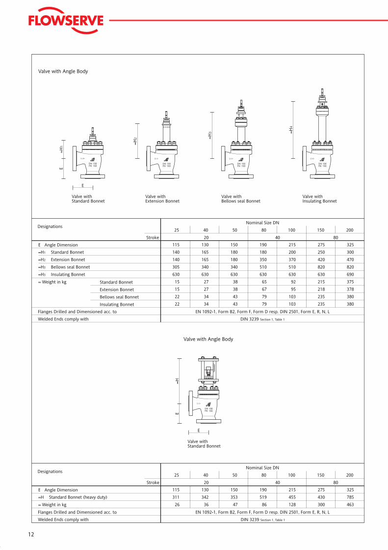
Valve with Angle Body
Valve withStandard Bonnet
E
E≈H
100
0
DN 100PN 160
Valve with Angle Body
DN 100PN 160
Valve withBellows seal Bonnet
≈H3
Valve withExtension Bonnet
≈H2
DN 100PN 160
Valve withStandard Bonnet
≈H1
E
E
DN 100PN 160
DN 100PN 160
Valve withInsulating Bonnet
≈H4
Nominal Size DN
E Angle Dimension
Stroke
Welded Ends comply with
40 80
≈H Standard Bonnet (heavy duty)
DIN 3239 Section 1, Table 1
≈ Weight in kg
Flanges Drilled and Dimensioned acc. to
Designations25
115
311
26
20
40
130
342
36
50
150
353
47
80
190
519
86
100
215
455
128
150
275
430
300
200
325
785
463
EN 1092-1, Form B2, Form F, Form D resp. DIN 2501, Form E, R, N, L
Nominal Size DN
E Angle Dimension
Stroke
Welded Ends comply with
40 80
≈H1 Standard Bonnet
DIN 3239 Section 1, Table 1
≈ Weight in kg
Flanges Drilled and Dimensioned acc. to EN 1092-1, Form B2, Form F, Form D resp. DIN 2501, Form E, R, N, L
Standard Bonnet
Extension Bonnet
Designations
≈H2 Extension Bonnet
≈H3 Bellows seal Bonnet
Bellows seal Bonnet
25
115
140
140
15
15
20
40
130
165
165
27
27
50
150
180
180
38
38
80
190
180
350
65
67
100
215
200
370
92
95
150
275
250
420
215
218
200
325
300
470
375
378
305
22
340
34
340
43
510
79
510
103
820
235
820
380
≈H3 Insulating Bonnet 630 630 630 630 630 630 690
Insulating Bonnet 22 34 43 79 103 235 380
13
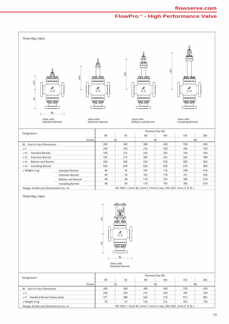
Three-Way Valve
Three-Way Valve
Valve withStandard Bonnet
≈h
BL
DN 100PN 100
≈H
100
0
Valve withStandard Bonnet
≈H1
≈h
BL
DN 100PN 100
Valve withExtension Bonnet
≈H2
DN 100PN 100
Valve withBellows seal Bonnet
≈H3
DN 100PN 100
Valve withInsulating Bonnet
DN 100PN 100
≈H5
Nominal Size DN
BL Face to Face Dimensions
Stroke
≈ h
20 40 80
≈ H Standard Bonnet (heavy duty)
Flanges Drilled and Dimensioned acc. to
Designations
≈ Weight in kg
40
260
371
240
50
50
300
388
250
67
80
380
560
310
126
100
430
510
350
212
150
550
813
450
433
200
650
895
550
742
EN 1092-1, Form B2, Form F, Form D resp. DIN 2501, Form E, R, N, L
Nominal Size DN
BL Face to Face Dimensions
Stroke
≈ h
20 40 80
≈ H1 Standard Bonnet
Flanges Drilled and Dimensioned acc. to
Designations
≈ H2 Extension Bonnet
≈ Weight in kg Standard Bonnet
Extension Bonnet
≈ H3 Bellows seal Bonnet
Bellows seal Bonnet
40
260
195
195
240
40
40
50
300
215
215
250
56
56
80
380
220
390
310
105
105
100
430
255
425
350
176
178
150
550
330
505
450
348
351
200
650
410
580
550
654
656
360
48
360
64
550
118
550
193
905
385
905
674
EN 1092-1, Form B2, Form F, Form D resp. DIN 2501, Form E, R, N, L
≈ H5 Insulating Bonnet 650 650 650 650 670 800
Insulating Bonnet 48 64 118 193 385 674
FlowPro TM - High Performance Valveflowserve.com
14
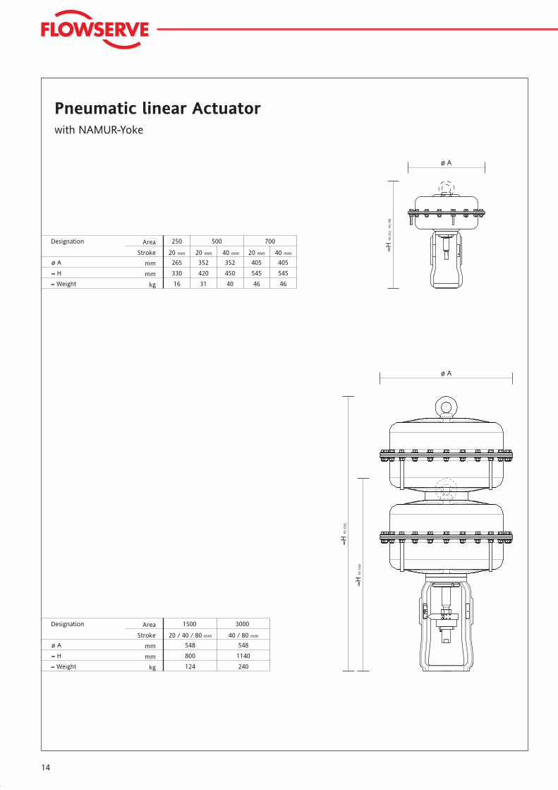
≈H PD
252
- P
D 7
00
ø A
Designation
≈ Weight
1500
ø A
≈ H
kg
mm
mm
Area
Stroke 20 / 40 / 80 mm
3000
548
800
124
40 / 80 mm
548
1140
240
≈H PD
300
2
≈H PD
150
2
ø A
Pneumatic linear Actuatorwith NAMUR-Yoke
Designation
≈ Weight
250 500 700
ø A
≈ H
kg
mm
mm
Area
Stroke 20 mm 40 mm 20 mm
405352352265
40 mm
405
545
46
450
40
420
31
330
16
545
46
20 mm
15
Designation
≈ Weight
ø A
≈ H
kg
m
m
m
m
Thrust Unit
Stroke
ø A
≈H
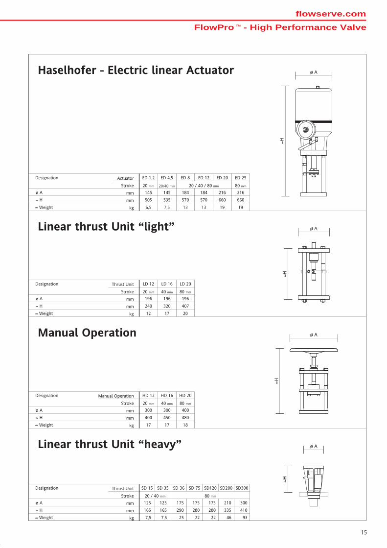
Linear thrust Unit “heavy”
20 / 40 mm 80 mm
SD 15 SD 35 SD 36 SD 75 SD120 SD200 SD300
93
300
410
46
210
335
22
175
280
22
175
280
175
290
7,5 25
125
165
7,5
125
165
ø A
≈H
ø A
≈HDesignation
≈ Weight
LD 20
ø A
≈ H
kg
m
m
m
m
Thrust Unit
Stroke 20 mm 40 mm 80 mm
LD 16LD 12
196
407
20
196
320
17
196
240
12
ø A
≈H
Haselhofer - Electric linear Actuator
Linear thrust Unit “light”
Designation
≈ Weight
ED 25
ø A
≈ H
20 mm 20/40 mm 80 mm
216
660
19
184
570
13
216
660
19
184
570
13
145
535
7,5
145
505
6,5
ED 20ED 1,2 ED 4,5 ED 8 ED 12
20 / 40 / 80 mm
kg
m
m
m
m
Actuator
Stroke
Manual Operation
Designation
≈ Weight
HD 20
ø A
≈ H
kg
m
m
m
m
Manual Operation
Stroke 20 mm 40 mm 80 mm
HD 16HD 12
400
480
18
300
450
17
300
400
17
FlowPro TM - High Performance Valveflowserve.com
16
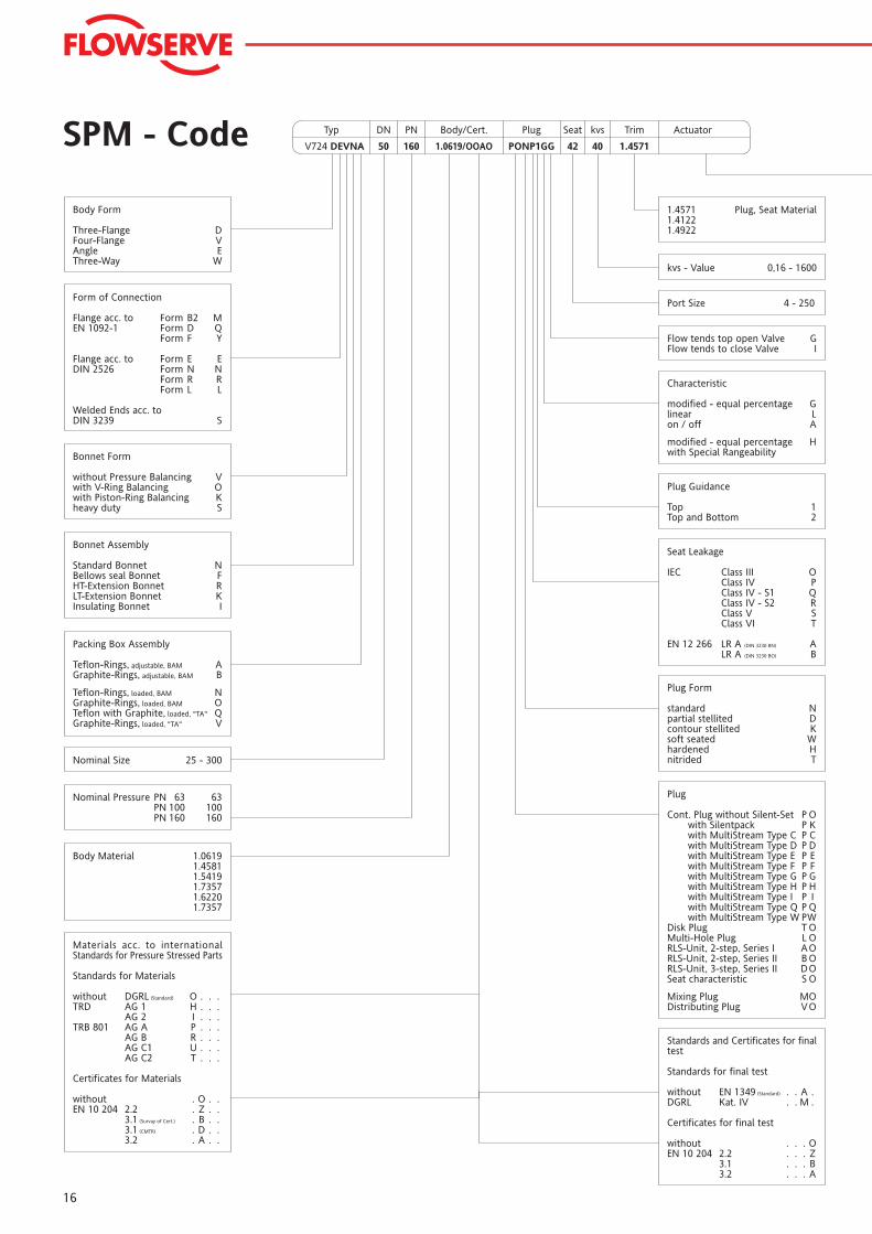
SPM - Code
Nominal Size 25 - 300
Body Form
Three-Flange DFour-Flange VAngle EThree-Way W
kvs - Value 0,16 - 1600
Port Size 4 - 250
Flow tends top open Valve GFlow tends to close Valve I
Characteristic
modified - equal percentage Glinear Lon / off A
modified - equal percentage Hwith Special Rangeability
Plug Guidance
Top 1Top and Bottom 2
Standards and Certificates for finaltest
Standards for final test
without EN 1349 (Standard) . . A .DGRL Kat. IV . . M .
Certificates for final test
without . . . OEN 10 204 2.2 . . . Z
3.1 . . . B3.2 . . . A
Plug Form
standard Npartial stellited Dcontour stellited Ksoft seated Whardened Hnitrided T
Seat Leakage
IEC Class III OClass IV PClass IV - S1 QClass IV - S2 RClass V SClass VI T
EN 12 266 LR A (DIN 3230 BN) ALR A (DIN 3230 BO) B
50V724 DEVNA 160 1.0619/OOAO PONP1GG 42 40 1.4571
Typ DN PN Body/Cert. Plug Seat kvs Trim Actuator
Form of Connection
Flange acc. to Form B2 MEN 1092-1 Form D Q
Form F Y
Flange acc. to Form E EDIN 2526 Form N N
Form R RForm L L
Welded Ends acc. toDIN 3239 S
Bonnet Form
without Pressure Balancing Vwith V-Ring Balancing Owith Piston-Ring Balancing Kheavy duty S
Packing Box Assembly
Teflon-Rings, adjustable, BAM AGraphite-Rings, adjustable, BAM B
Teflon-Rings, loaded, BAM NGraphite-Rings, loaded, BAM OTeflon with Graphite, loaded, "TA" QGraphite-Rings, loaded, "TA" V
Nominal Pressure PN 63 63PN 100 100PN 160 160
Materials acc. to internationalStandards for Pressure Stressed Parts
Standards for Materials
without DGRL (Standard) O . . .TRD AG 1 H . . .
AG 2 I . . .TRB 801 AG A P . . .
AG B R . . .AG C1 U . . .AG C2 T . . .
Certificates for Materials
without . O . .EN 10 204 2.2 . Z . .
3.1 (Survay of Cert.) . B . .3.1 (CMTR) . D . .3.2 . A . .
1.4571 Plug, Seat Material1.41221.4922
Plug
Cont. Plug without Silent-Set P Owith Silentpack P Kwith MultiStream Type C P Cwith MultiStream Type D P Dwith MultiStream Type E P Ewith MultiStream Type F P Fwith MultiStream Type G P Gwith MultiStream Type H P Hwith MultiStream Type I P Iwith MultiStream Type Q P Qwith MultiStream Type W PW
Disk Plug T OMulti-Hole Plug L ORLS-Unit, 2-step, Series I AORLS-Unit, 2-step, Series II B ORLS-Unit, 3-step, Series II DOSeat characteristic S O
Mixing Plug MODistributing Plug VO
Body Material 1.06191.45811.54191.73571.62201.7357
Bonnet Assembly
Standard Bonnet NBellows seal Bonnet FHT-Extension Bonnet RLT-Extension Bonnet KInsulating Bonnet I
17
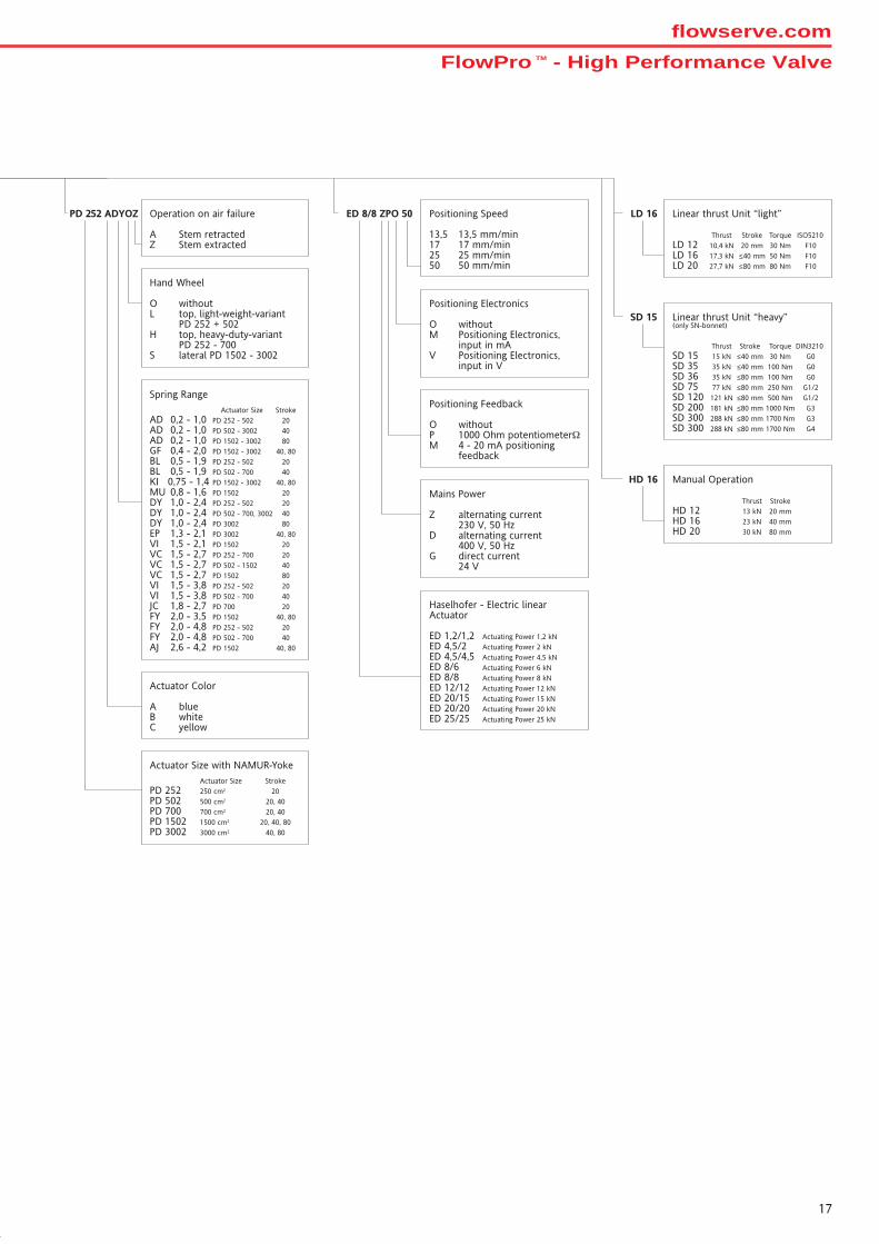
LD 16ED 8/8 ZPO 50 Positioning Speed
13,5 13,5 mm/min17 17 mm/min25 25 mm/min50 50 mm/min
Positioning Electronics
O withoutM Positioning Electronics,
input in mAV Positioning Electronics,
input in V
Positioning Feedback
O withoutP 1000 Ohm potentiometerΩM 4 - 20 mA positioning
feedback
Mains Power
Z alternating current230 V, 50 Hz
D alternating current400 V, 50 Hz
G direct current24 V
Haselhofer - Electric linearActuator
ED 1,2/1,2 Actuating Power 1,2 kNED 4,5/2 Actuating Power 2 kNED 4,5/4,5 Actuating Power 4,5 kNED 8/6 Actuating Power 6 kNED 8/8 Actuating Power 8 kNED 12/12 Actuating Power 12 kNED 20/15 Actuating Power 15 kNED 20/20 Actuating Power 20 kNED 25/25 Actuating Power 25 kN
PD 252 ADYOZ Operation on air failure
A Stem retractedZ Stem extracted
Actuator Color
A blueB whiteC yellow
Actuator Size with NAMUR-Yoke
Actuator Size StrokePD 252 250 cm2 20PD 502 500 cm2 20, 40PD 700 700 cm2 20, 40PD 1502 1500 cm2 20, 40, 80PD 3002 3000 cm2 40, 80
HD 16
Spring Range
Actuator Size StrokeAD 0,2 - 1,0 PD 252 - 502 20AD 0,2 - 1,0 PD 502 - 3002 40AD 0,2 - 1,0 PD 1502 - 3002 80GF 0,4 - 2,0 PD 1502 - 3002 40, 80BL 0,5 - 1,9 PD 252 - 502 20BL 0,5 - 1,9 PD 502 - 700 40KI 0,75 - 1,4 PD 1502 - 3002 40, 80MU 0,8 - 1,6 PD 1502 20DY 1,0 - 2,4 PD 252 - 502 20DY 1,0 - 2,4 PD 502 - 700, 3002 40DY 1,0 - 2,4 PD 3002 80EP 1,3 - 2,1 PD 3002 40, 80VI 1,5 - 2,1 PD 1502 20VC 1,5 - 2,7 PD 252 - 700 20VC 1,5 - 2,7 PD 502 - 1502 40VC 1,5 - 2,7 PD 1502 80VI 1,5 - 3,8 PD 252 - 502 20VI 1,5 - 3,8 PD 502 - 700 40JC 1,8 - 2,7 PD 700 20FY 2,0 - 3,5 PD 1502 40, 80FY 2,0 - 4,8 PD 252 - 502 20FY 2,0 - 4,8 PD 502 - 700 40AJ 2,6 - 4,2 PD 1502 40, 80
Hand Wheel
O withoutL top, light-weight-variant
PD 252 + 502H top, heavy-duty-variant
PD 252 - 700S lateral PD 1502 - 3002
SD 15
Linear thrust Unit “light”
Thrust Stroke Torque ISO5210LD 12 10,4 kN 20 mm 30 Nm F10LD 16 17,3 kN ≤40 mm 50 Nm F10LD 20 27,7 kN ≤80 mm 80 Nm F10
Manual Operation
Thrust StrokeHD 12 13 kN 20 mmHD 16 23 kN 40 mmHD 20 30 kN 80 mm
Linear thrust Unit “heavy”(only SN-bonnet)
Thrust Stroke Torque DIN3210SD 15 15 kN ≤40 mm 30 Nm G0SD 35 35 kN ≤40 mm 100 Nm G0SD 36 35 kN ≤80 mm 100 Nm G0SD 75 77 kN ≤80 mm 250 Nm G1/2SD 120 121 kN ≤80 mm 500 Nm G1/2SD 200 181 kN ≤80 mm 1000 Nm G3SD 300 288 kN ≤80 mm 1700 Nm G3SD 300 288 kN ≤80 mm 1700 Nm G4
FlowPro TM - High Performance Valveflowserve.com

18

FlowPro TM - High Performance Valveflowserve.com
19
SAEEBRV724-01 01.10
Your contact:
TM indicates a trade mark of Flowserve.Infomation given in this product specification sheet is made in good faith and based upon specific testing but does not, however, constitute a guarantee.
Modifications without notice in line with technical progress.PSS 108292 05/07 V724 en
Flowserve (Austria) GmbHControl Valves - Villach Operation
Kasernengasse 69500 VillachAustria
Tel.: +43 (0) 4242 41181-0Fax.: +43 (0) 4242 41181-50
www.flowserve.comwww.flowserve-villach.com