dnetb001 r11 dnet-ip2 serial communication …ampcontrol pty ltd – abn 28 000 915 542 dnet-ip2...
TRANSCRIPT

Version: 11, June 2016
Designed and manufactured in Australia by Ampcontrol Pty Ltd
DNET-IP2 SERIAL COMMUNICATION SYSTEM
User Manual

Ampcontrol Pty Ltd – ABN 28 000 915 542
DNET-IP2 SERIAL COMMUNICATION SYSTEM USER MANUAL
DNETB001 Version 11 – JUN 2016
Uncontrolled Copy - Refer to Ampcontrol Website for Latest Version Page 2 of 70
AP
PR
OV
ED
FO
R E
XT
ER
NA
L D
IST
RIB
UT
ION
– P
RO
PE
RT
Y O
F A
MP
CO
NT
RO
L P
TY
LT
D
–
NO
T T
O B
E R
EP
RO
DU
CE
D IN
PA
RT
WARNING!
The warning symbol highlights a potential risk of injury or death.
Please share these warnings with other operators.
CAUTION!
The caution symbol highlights a potential risk of damage to equipment.
Please share these cautions with other operators.
NOTE
The note symbol highlights key information.
Please share these notes with other operators.
ENVIRO
The enviro (environmental) symbol highlights areas which may have an impact on the surrounding fauna and/or flora.

Ampcontrol Pty Ltd – ABN 28 000 915 542
DNET-IP2 SERIAL COMMUNICATION SYSTEM USER MANUAL
DNETB001 Version 11 – JUN 2016
Uncontrolled Copy - Refer to Ampcontrol Website for Latest Version Page 3 of 70
AP
PR
OV
ED
FO
R E
XT
ER
NA
L D
IST
RIB
UT
ION
– P
RO
PE
RT
Y O
F A
MP
CO
NT
RO
L P
TY
LT
D
–
NO
T T
O B
E R
EP
RO
DU
CE
D IN
PA
RT
Copyright Notice
The Ampcontrol DNET-IP2 Serial Communication System described in this document is the property of AMPCONTROL PTY LTD. It is furnished under a license agreement and is to be used only in accordance with the terms of the agreement.
No part of the hardware or documentation may be reproduced, transmitted, transcribed, stored in a retrieval system, or translated into any language or computer language, in any form or by any means, without prior written permission of AMPCONTROL PTY LTD.
Disclaimer
While every effort has been made to assure the accuracy and clarity of this document, AMPCONTROL PTY LTD assumes no liability resulting from any omissions in this document, or from misuse of the information obtained herein. The information in this document has been carefully checked and is believed to be entirely reliable with all of the necessary information included. AMPCONTROL PTY LTD reserves the right to make changes to any products described herein to improve reliability, function, or design, and reserves the right to revise this document and make changes from time to time in content hereof with no obligation to notify any persons of revisions or changes. AMPCONTROL PTY LTD does not assume any liability arising out of the application or any use of any product or circuit described herein; neither does it convey license under its patent rights or the rights of others.
Before You Begin
Thank you for purchasing the Ampcontrol DNET Serial Communication System.
WARNING!
In the interests of safety and correct equipment operation, please take the time to read and understand the content in this manual.
Ampcontrol Contact Details
7 Billbrooke Close, Cameron Park, NSW, 2285
P +61 1300 267 373 | F +61 2 4903 4888
EMAIL: [email protected]
WEB: ampcontrolgroup.com

Ampcontrol Pty Ltd – ABN 28 000 915 542
DNET-IP2 SERIAL COMMUNICATION SYSTEM USER MANUAL
DNETB001 Version 11 – JUN 2016
Uncontrolled Copy - Refer to Ampcontrol Website for Latest Version Page 4 of 70
AP
PR
OV
ED
FO
R E
XT
ER
NA
L D
IST
RIB
UT
ION
– P
RO
PE
RT
Y O
F A
MP
CO
NT
RO
L P
TY
LT
D
–
NO
T T
O B
E R
EP
RO
DU
CE
D IN
PA
RT
TABLE OF CONTENTS
1 SAFETY AND OTHER WARNINGS .................................................................. 6
1.1 Safe Use of Equipment .............................................................................. 6
2 RECEIVING AND STORAGE ............................................................................ 7
2.1 Receiving ................................................................................................... 7
2.2 Inspection .................................................................................................. 7
2.3 Storage after Delivery ................................................................................ 7
2.4 Unpacking of Equipment ............................................................................ 7
3 DNET-IP2 COMMUNICATION SYSTEM OVERVIEW ....................................... 8
3.1 DNET-IP2 Protocol Converter .................................................................... 9
3.2 IPSI Module ............................................................................................... 9
3.3 DNET-IP2 Power Supply ......................................................................... 10
4 INSTALLATION ............................................................................................... 11
4.1 General Warnings .................................................................................... 11
4.2 Mandatory Installation Practices .............................................................. 11
4.3 Mechanical Installation Information .......................................................... 12
4.4 Electrical Installation Information ............................................................. 14
4.5 Intrinsically Safe Communications Link .................................................... 15
5 PRODUCT OPERATION ................................................................................. 16
5.1 DNET-IP2 Protocol Converter .................................................................. 16
5.2 DNET Power Supply ................................................................................ 17
5.3 IPSI-IPA ................................................................................................... 17
5.4 IPSI-D ...................................................................................................... 17
6 COMMUNICATION PROTOCOLS .................................................................. 18
6.1 Master Modbus RTU ................................................................................ 18
6.2 Slave Modbus RTU .................................................................................. 19
6.3 Modbus Autoscan .................................................................................... 21
6.4 IP Protocol (IP2 Protocol Mode with Slave ID Address = 0) ..................... 22
6.5 IP2 Protocol (IP2 Protocol Mode with Slave ID Address = 1…8) .............. 22
7 TRANSLATION TABLES ................................................................................. 24
7.1 IPD 11kV Translation Table ..................................................................... 24
7.2 IPD Translation Table .............................................................................. 28
7.3 IPC Translation Table .............................................................................. 33
7.4 HPB 22kV Translation Table (Standard and Low EL Version) .................. 37
7.5 HPB Translation Table ............................................................................. 41
7.6 IPB Translation Table .............................................................................. 45
7.7 IPA V4/5.1 Translation Table ................................................................... 49

Ampcontrol Pty Ltd – ABN 28 000 915 542
DNET-IP2 SERIAL COMMUNICATION SYSTEM USER MANUAL
DNETB001 Version 11 – JUN 2016
Uncontrolled Copy - Refer to Ampcontrol Website for Latest Version Page 5 of 70
AP
PR
OV
ED
FO
R E
XT
ER
NA
L D
IST
RIB
UT
ION
– P
RO
PE
RT
Y O
F A
MP
CO
NT
RO
L P
TY
LT
D
–
NO
T T
O B
E R
EP
RO
DU
CE
D IN
PA
RT
8 SERVICE, MAINTENANCE & DISPOSAL ....................................................... 52
8.1 Equipment Service ................................................................................... 52
8.2 Equipment Maintenance .......................................................................... 53
8.3 Disposal ................................................................................................... 53
9 SPECIFICATIONS .......................................................................................... 54
9.1 DNET-IP2 Protocol Converter .................................................................. 54
9.2 DNET Power Supply V2 (Supersedes V1) ............................................... 54
9.3 IPSI-IPA ................................................................................................... 54
9.4 IPSI-D ...................................................................................................... 54
10 EQUIPMENT LIST ........................................................................................ 55
APPENDIX A - DRAWINGS ............................................................................... 56
APPENDIX B – APPROVALS ............................................................................ 63
APPENDIX C- RISK & RELIABILITY .................................................................. 70
TABLE OF FIGURES
Figure 3.1: DNET-IP2 Communication System – Typical System Overview..... 8
Figure 3.2: DNET-IP2 Protocol Converter ........................................................ 9
Figure 3.3: IPSI-D Module (Left) and legacy IPSI Module (Right) .................... 9
Figure 3.4: DNET-IP2 Power Supply V2 ........................................................ 10
Figure 3.5: DNET-IP2 Power Supply V1 (Obsolete) ....................................... 10
Figure 4.1: DNET-IP2 Protocol Converter Dimensions .................................. 12
Figure 4.2: DNET Power Supply Dimensions ................................................. 12
Figure 4.3: IPSI-IPA Module & IPSI-IPA Base Dimensions ............................ 13
Figure 4.4: IPSI-D Module Dimensions .......................................................... 13
Figure 4.5: DNET-IP2 Serial Communication System Typical
Connection Diagram ...................................................................................... 14

Ampcontrol Pty Ltd – ABN 28 000 915 542
DNET-IP2 SERIAL COMMUNICATION SYSTEM USER MANUAL
DNETB001 Version 11 – JUN 2016
Uncontrolled Copy - Refer to Ampcontrol Website for Latest Version Page 6 of 70
AP
PR
OV
ED
FO
R E
XT
ER
NA
L D
IST
RIB
UT
ION
– P
RO
PE
RT
Y O
F A
MP
CO
NT
RO
L P
TY
LT
D
–
NO
T T
O B
E R
EP
RO
DU
CE
D IN
PA
RT
1 SAFETY AND OTHER WARNINGS
For safety reasons, the DNET-IP2 Serial Communication System must be installed, operated and serviced only by competent personnel. Please read and understand this instruction manual completely before installing, operating or servicing this equipment. Failure to install or operate this instrument in accordance with the instructions contained in this manual may create hazardous operating conditions.
1.1 Safe Use of Equipment The equipment supplied has been designed and manufactured to ensure safe operation. The equipment must only be used within the design parameters.
The instructions within this manual must be observed as an aid towards achieving the safest possible installation.
Persons responsible for installation, maintenance, or operation, must observe the following instructions:
1.1.1 Changes to Equipment
Changes in the design and modifications to the equipment are not permitted. Unauthorised changes made to the hardware or operating firmware will void the manufacturer's warranty, and may compromise the integrity of the system into which it is installed and other connected equipment.
1.1.2 Equipment Knowledge
Experience with, or understanding of, this equipment is essential for the safe installation and removal of the equipment. Therefore, please read and understand this manual prior to use. Competency based training courses are recommended and are available on request.
1.1.3 Manual Handling
Precautions have been taken to ensure all equipment is safe to handle and free from sharp edges. However care should always be taken when handling enclosures and gloves should be worn.
1.1.4 Installation
Correct operation and safety depend on the DNET-IP2 Serial Communication System and associated equipment being installed correctly. Mechanical and or electrical installation and maintenance of plant and equipment must only be carried out by appropriately qualified personnel and must be tested thoroughly prior to operation.
Ampcontrol Pty Ltd – ABN 28 000 915 542
DNET-IP2 SERIAL COMMUNICATION SYSTEM USER MANUAL
DNETB001 Version 11 – JUN 2016
Uncontrolled Copy - Refer to Ampcontrol Website for Latest Version Page 7 of 70
AP
PR
OV
ED
FO
R E
XT
ER
NA
L D
IST
RIB
UT
ION
– P
RO
PE
RT
Y O
F A
MP
CO
NT
RO
L P
TY
LT
D
–
NO
T T
O B
E R
EP
RO
DU
CE
D IN
PA
RT
2 RECEIVING AND STORAGE
2.1 Receiving
All possible precautions are taken to protect the equipment against damage or losses during shipment, however before accepting delivery, check all items against the packing list or bill of loading. If there is evidence of physical damage, notify Ampcontrol immediately.
Notify Ampcontrol immediately in case of any discrepancies to the packing list. Keep a record of any claims and correspondence. Photographs are recommended.
Where practicable do not remove protective covers prior to installation unless there are indications of damage. Boxes opened for inspection and inventory should be carefully repacked to ensure protection of the contents or else the parts should be packaged and stored in a safe place. Examine all packing boxes, wrappings and covers for items attached to them, retain and store any approval documentation for your safety file as applicable prior to wrapping being discarded.
2.2 Inspection
Equipment that is found to be damaged or has been modified away from its published specification must not be used. Please contact Ampcontrol if the equipment is suspected to be different than that ordered or if it does not match the published specifications.
2.3 Storage after Delivery
When the equipment is not to be installed immediately, proper storage is important to ensure protection of equipment and validity of warranty.
All equipment should be stored indoors between 0-40˚C, preferably on shelves and protected from moisture and sunlight.
2.4 Unpacking of Equipment
The method of packing used will depend on the size and quantity of the equipment. The following cautions should be interpreted as appropriate.
CAUTION!
Take care when unpacking crates as the contents may have shifted during transport.
ENVIRO
The disposal of packaging materials, replaced parts, or components must comply with environmental restrictions without polluting the soil,
air or water.
Ensure that any timber and cardboard used as packaging is disposed of in a safe and environmentally responsible manner.
Where possible, dispose of all waste products i.e. oils, metals, plastic and rubber products by using an approved recycling service centre.
Ampcontrol Pty Ltd – ABN 28 000 915 542
DNET-IP2 SERIAL COMMUNICATION SYSTEM USER MANUAL
DNETB001 Version 11 – JUN 2016
Uncontrolled Copy - Refer to Ampcontrol Website for Latest Version Page 8 of 70
AP
PR
OV
ED
FO
R E
XT
ER
NA
L D
IST
RIB
UT
ION
– P
RO
PE
RT
Y O
F A
MP
CO
NT
RO
L P
TY
LT
D
–
NO
T T
O B
E R
EP
RO
DU
CE
D IN
PA
RT
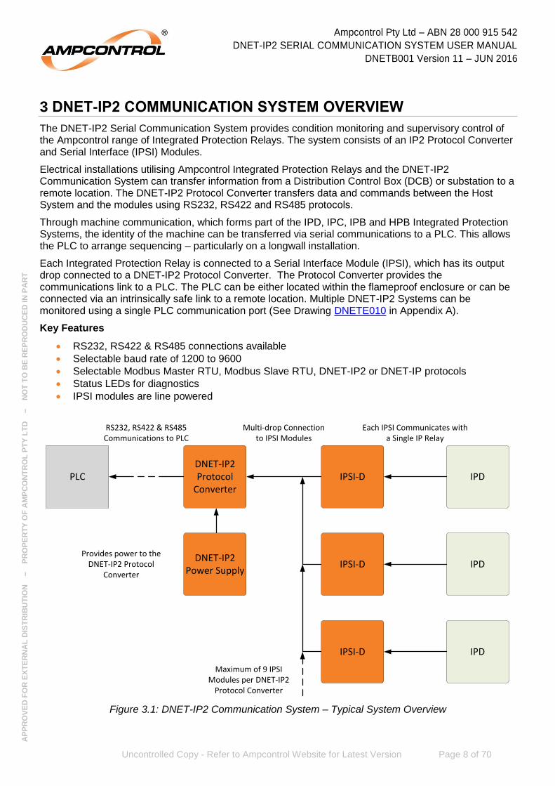
3 DNET-IP2 COMMUNICATION SYSTEM OVERVIEW
The DNET-IP2 Serial Communication System provides condition monitoring and supervisory control of the Ampcontrol range of Integrated Protection Relays. The system consists of an IP2 Protocol Converter and Serial Interface (IPSI) Modules.
Electrical installations utilising Ampcontrol Integrated Protection Relays and the DNET-IP2 Communication System can transfer information from a Distribution Control Box (DCB) or substation to a remote location. The DNET-IP2 Protocol Converter transfers data and commands between the Host System and the modules using RS232, RS422 and RS485 protocols.
Through machine communication, which forms part of the IPD, IPC, IPB and HPB Integrated Protection Systems, the identity of the machine can be transferred via serial communications to a PLC. This allows the PLC to arrange sequencing – particularly on a longwall installation.
Each Integrated Protection Relay is connected to a Serial Interface Module (IPSI), which has its output drop connected to a DNET-IP2 Protocol Converter. The Protocol Converter provides the communications link to a PLC. The PLC can be either located within the flameproof enclosure or can be connected via an intrinsically safe link to a remote location. Multiple DNET-IP2 Systems can be monitored using a single PLC communication port (See Drawing DNETE010 in Appendix A).
Key Features
RS232, RS422 & RS485 connections available
Selectable baud rate of 1200 to 9600
Selectable Modbus Master RTU, Modbus Slave RTU, DNET-IP2 or DNET-IP protocols
Status LEDs for diagnostics
IPSI modules are line powered
Figure 3.1: DNET-IP2 Communication System – Typical System Overview
DNET-IP2 Protocol
Converter
DNET-IP2 Power Supply
IPSI-D IPD
IPSI-D IPD
IPSI-D IPD
PLC
RS232, RS422 & RS485Communications to PLC
Multi-drop Connection to IPSI Modules
Maximum of 9 IPSI Modules per DNET-IP2
Protocol Converter
Each IPSI Communicates with a Single IP Relay
Provides power to the DNET-IP2 Protocol
Converter

Ampcontrol Pty Ltd – ABN 28 000 915 542
DNET-IP2 SERIAL COMMUNICATION SYSTEM USER MANUAL
DNETB001 Version 11 – JUN 2016
Uncontrolled Copy - Refer to Ampcontrol Website for Latest Version Page 9 of 70
AP
PR
OV
ED
FO
R E
XT
ER
NA
L D
IST
RIB
UT
ION
– P
RO
PE
RT
Y O
F A
MP
CO
NT
RO
L P
TY
LT
D
–
NO
T T
O B
E R
EP
RO
DU
CE
D IN
PA
RT
3.1 DNET-IP2 Protocol Converter The DNET-IP2 Protocol Converter provides an interface between an external communications device and the Ampcontrol Integrated Protection relay suite (IPA, IPB, IPC, IPD & HPB).
The Protocol Converter has a serial communication port that is electrically isolated and supports RS232, RS422 and RS485 protocols with a selectable baud rate of 1200 to 9600.
The four user selectable protocols are:
Modbus Master RTU
Modbus Slave RTU
DNET-IP2
DNET-IP
The IP2 Line Driver drives a two-wire communication line, which delivers power and exchanges data with a maximum of nine IPSI Modules.
Figure 3.2: DNET-IP2 Protocol Converter
3.2 IPSI Module The IPSI module provides a communications interface between the DNET-IP2 Protocol Converter and an Integrated Protection relay. An IPSI module is required for each Integrated Protection relay that is to be connected to the Protocol Converter.
There are two types of IPSI module that are compatible with the DNET-IP2 Serial Communication System – the IPSI and the IPSI-D. The IPSI is a legacy module that is used for communicating with the IPA, IPB, IPC and HPB Integrated Protection relays. The IPSI-D is used for communicating with the IPD Integrated Protection relay.
Figure 3.3: IPSI-D Module (Left) and legacy IPSI Module (Right)

Ampcontrol Pty Ltd – ABN 28 000 915 542
DNET-IP2 SERIAL COMMUNICATION SYSTEM USER MANUAL
DNETB001 Version 11 – JUN 2016
Uncontrolled Copy - Refer to Ampcontrol Website for Latest Version Page 10 of 70
AP
PR
OV
ED
FO
R E
XT
ER
NA
L D
IST
RIB
UT
ION
– P
RO
PE
RT
Y O
F A
MP
CO
NT
RO
L P
TY
LT
D
–
NO
T T
O B
E R
EP
RO
DU
CE
D IN
PA
RT
3.3 DNET-IP2 Power Supply The DNET-IP Power Supply converts an 110V supply to a 24V-0V-24V supply for the DNET-IP Protocol Converter. In 2014, the DNET-IP Power Supply V1 was superseded by the DNET-IP Power Supply V2.
NOTE
The V2 power supply provides more efficient power to the DNET system, hence reducing the likelihood of faults developing from
overheating.
Both the V1 and V2 power supplies are compatible with the DNET-IP2 V1 Protocol Converter. V1 power supplies should be changed over
to V2 when production permits.
Figure 3.4: DNET-IP2 Power Supply V2
Figure 3.5: DNET-IP2 Power Supply V1 (Obsolete)

Ampcontrol Pty Ltd – ABN 28 000 915 542
DNET-IP2 SERIAL COMMUNICATION SYSTEM USER MANUAL
DNETB001 Version 11 – JUN 2016
Uncontrolled Copy - Refer to Ampcontrol Website for Latest Version Page 11 of 70
AP
PR
OV
ED
FO
R E
XT
ER
NA
L D
IST
RIB
UT
ION
– P
RO
PE
RT
Y O
F A
MP
CO
NT
RO
L P
TY
LT
D
–
NO
T T
O B
E R
EP
RO
DU
CE
D IN
PA
RT
4 INSTALLATION
4.1 General Warnings
These instructions have been designed to assist users of the DNET-IP2 Serial Communication System (hereafter referred to as the “System”) with installation.
Before the System can be installed, there are a number of things that need to be considered and understood to prevent incorrect or unsafe operation of the System or the system into which it is installed.
Along with relevant competence, and an understanding of the target application, the following points should be considered:
4.1.1 Ensure that the information provided in this user manual is fully understood.
It is extremely important that the limitations and functionality of the System are understood to prevent incorrect installation and use from creating a potentially dangerous risk. If in doubt as to the nature of the limitations or their implication, consult a competent authority such as a supervisor or Ampcontrol technical representative.
4.1.2 Ensure that the application into which the System is being installed has been properly defined, designed and approved.
Any system intended to mitigate the risk of injury needs to be properly designed and implemented. Such a system must be the result of structured risk analysis with the outcomes used to define the system requirements. These requirements, in turn, will guide the choice of instrumentation, logic solvers and actuators needed to implement the system. Understanding the needs of the system will ensure proper selection of equipment.
4.1.3 Ensure that the System will properly perform the required functions within the system design.
It is important to understand how the System is intended to interact with other equipment within a system. For safe and reliable use, it is crucial that neither the System logical operation nor its signalling be compromised by incompatibilities with connected equipment.
4.1.4 Modifications of any form to the System are prohibited.
If modifications of any form are made to the System, the equipment may no longer be fit for use. If any modifications or damage to the System is evident, do not use the equipment and contact Ampcontrol for advice.
4.2 Mandatory Installation Practices
The following information must be adhered to when installing the System. Failure to adhere to this information may give rise to unsafe operation.
Using the System in a manner that exceeds its electrical, functional or physical specifications, or in a way that is contrary to its operating restrictions, may create risks to personnel and/or equipment resulting in injury or death.
The System must be powered within the specified voltage range.
The installation of the System must be carried out by suitably trained and qualified personnel.
Identification labels fixed to the System must not be damaged, removed or covered before, during or after installation.
The installation is to be in accordance with the relevant installation Standards/Codes of Practice.
Modifications must not be made to any part of the System
Complete and accurate records of the installation must be kept as part of the site installation.

Ampcontrol Pty Ltd – ABN 28 000 915 542
DNET-IP2 SERIAL COMMUNICATION SYSTEM USER MANUAL
DNETB001 Version 11 – JUN 2016
Uncontrolled Copy - Refer to Ampcontrol Website for Latest Version Page 12 of 70
AP
PR
OV
ED
FO
R E
XT
ER
NA
L D
IST
RIB
UT
ION
– P
RO
PE
RT
Y O
F A
MP
CO
NT
RO
L P
TY
LT
D
–
NO
T T
O B
E R
EP
RO
DU
CE
D IN
PA
RT
4.3 Mechanical Installation Information
4.3.1 DNET-IP2 Protocol Converter
The DNET-IP2 Protocol Converter is housed in an IP20 plastic enclosure that is either DIN rail mountable or panel mountable (via 2 screws).
Figure 4.1: DNET-IP2 Protocol Converter Dimensions
4.3.2 DNET Power Supply
The DNET Power Supply (V1 & V2) is housed in an IP20 plastic enclosure that is either DIN rail mountable or panel mountable (via 2 screws).
Figure 4.2: DNET Power Supply Dimensions
75
110 100
Front ViewSide View
75
110 55
Front ViewSide View
Ampcontrol Pty Ltd – ABN 28 000 915 542
DNET-IP2 SERIAL COMMUNICATION SYSTEM USER MANUAL
DNETB001 Version 11 – JUN 2016
Uncontrolled Copy - Refer to Ampcontrol Website for Latest Version Page 13 of 70
AP
PR
OV
ED
FO
R E
XT
ER
NA
L D
IST
RIB
UT
ION
– P
RO
PE
RT
Y O
F A
MP
CO
NT
RO
L P
TY
LT
D
–
NO
T T
O B
E R
EP
RO
DU
CE
D IN
PA
RT
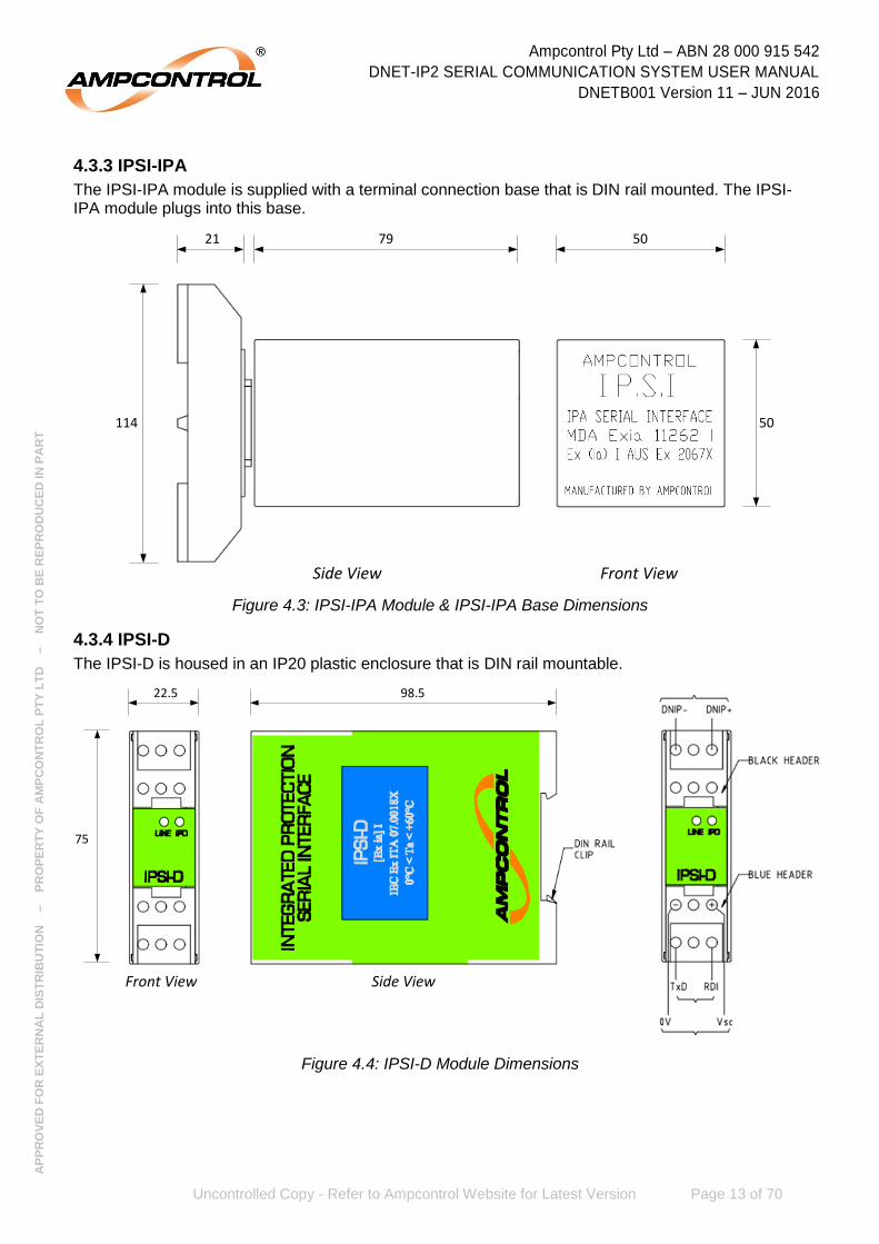
4.3.3 IPSI-IPA
The IPSI-IPA module is supplied with a terminal connection base that is DIN rail mounted. The IPSI-IPA module plugs into this base.
Figure 4.3: IPSI-IPA Module & IPSI-IPA Base Dimensions
4.3.4 IPSI-D
The IPSI-D is housed in an IP20 plastic enclosure that is DIN rail mountable.
Figure 4.4: IPSI-D Module Dimensions
21 79
Side View Front View
50
50114
22.5 98.5
75
Side ViewFront View

Ampcontrol Pty Ltd – ABN 28 000 915 542
DNET-IP2 SERIAL COMMUNICATION SYSTEM USER MANUAL
DNETB001 Version 11 – JUN 2016
Uncontrolled Copy - Refer to Ampcontrol Website for Latest Version Page 14 of 70
AP
PR
OV
ED
FO
R E
XT
ER
NA
L D
IST
RIB
UT
ION
– P
RO
PE
RT
Y O
F A
MP
CO
NT
RO
L P
TY
LT
D
–
NO
T T
O B
E R
EP
RO
DU
CE
D IN
PA
RT
4.4 Electrical Installation Information
Figure 4.5: DNET-IP2 Serial Communication System Typical Connection Diagram
4.4.1 DNET Power Supply – Incoming Supply (Terminals A, N & E)
The DNET Power Supply requires an incoming supply of 85-264VAC and has a power consumption of 15VA.
4.4.2 DNET Power Supply – Outgoing Supply (Terminals 24, 0 & 24)
The DNET Power Supply V2 produces a 24-0-24VDC output that is directly wired into the 20-0-20V inputs of the DNET-IP2 Protocol Converter. This connection is not polarity sensitive (0V must be wired to 0V).
The DNET Power Supply V1 produces a 20-0-20VAC output that is wired into the DNET-IP2 Protocol Converter in the same manner as described above.
NOTE
The V2 power supply provides more efficient power to the DNET system, hence reducing the likelihood of faults developing from
overheating.
Both the V1 and V2 power supplies are compatible with the DNET-IP2 V1 Protocol Converter. V1 power supplies should be changed over
to V2 when production permits.
4.4.3 DNET-IP2 Protocol Converter – Incoming Supply (Terminals 20, 0 & 20)
The DNET-IP2 Protocol Converter requires a 20-0-20VAC supply or a 24-0-24VDC supply. This supply is provided by the DNET Power Supply (see Section 4.4.2).
To IPD
DNET IP2 Protocol Converter*
TX-
RX+
RX-
TX+
To RS485 Device
1 2 3 4
OFF
ON
1
L+
L-
IPSI-D
VSD
0V
TXD
RDI1
DNP+
DNP-
To IPD
IPSI-D
VSD
0V
TXD
RDI
DNP+
DNP-
To other IPSI-D modules (maximum of 9 per
DNET-IP2 Protocol Converter)
2
20 0 20
*RS232 Terminals have been omitted
for clarity
TR+
TR-
DNET Power Supply V2
24 0 24
A
N
E
To 85-264VACPower Supply
Wiring between the DNET IP2 Protocol Converter and the last IPSI-D is to be kept
as short as possible (maximum of 10m)
Ampcontrol Pty Ltd – ABN 28 000 915 542
DNET-IP2 SERIAL COMMUNICATION SYSTEM USER MANUAL
DNETB001 Version 11 – JUN 2016
Uncontrolled Copy - Refer to Ampcontrol Website for Latest Version Page 15 of 70
AP
PR
OV
ED
FO
R E
XT
ER
NA
L D
IST
RIB
UT
ION
– P
RO
PE
RT
Y O
F A
MP
CO
NT
RO
L P
TY
LT
D
–
NO
T T
O B
E R
EP
RO
DU
CE
D IN
PA
RT
4.4.4 DNET-IP2 Protocol Converter – RS422/RS485 (Terminals Tx+, Tx-, Rx+ & Rx-)
These terminals provide the upstream serial communications connection point for users with the desire to use either RS422 or RS485. To use RS422 simply wire the Tx+, Tx-, Rx+ & Rx- in cross-over configuration to the upstream RS422 device. To use RS485 the Tx+ and Rx+ must be bridged together, as must the Tx- and Rx- terminals (see Figure 4.5).
4.4.5 DNET-IP2 Protocol Converter – RS232 (Terminals CTS, RTS, Tx, Rx & COM)
These terminals provide the upstream serial communications connection point for users with the desire to use RS232.
4.4.6 DNET-IP2 Protocol Converter – L1 Connection (Terminals L1+ & L1-)
These terminals are the connection point for the L1 bus that the IPSI modules are “multi-dropped” onto. The length of the L1 line should be kept as short as possible, with any “tee” lengths kept to a minimum. Ideally the L1 connections should be looped-out of the terminals on the IPSI.
A twisted pair cable should be used for this connection, and it should be run away from sources of electrical noise.
4.4.7 IPSI Connections
For information on connection to the DNET-IP2 Protocol Converter’s L1 bus, refer to Section 4.4.6.
For information on connection to the Integrated Protection relay, read the below in conjunction with referring to the individual IP relay user manuals.
Terminals 1, 2, 10 and 11 of the IPSI-D are intrinsically safe terminations and should be wired in accordance with AS 2381.7. Twisted conductors or overall screened cable should be used. The screen should be connected to 0V at both the Integrated Protection Relay and the IPSI Module.
CAUTION!
Connect the screen of the cable between the IP relay and the IPSI to the 0V terminal on the IP relay and the 0V terminal on the IPSI Module.
Do NOT connect the screen to earth.
4.5 Intrinsically Safe Communications Link An intrinsically safe link consisting of approved IS Barriers is required to allow Integrated Protection Relays to transmit their data from a hazardous area to a remote PLC. The equipment in the hazardous area must be enclosed in a flameproof enclosure.
4.5.1 PLC RS232 IS Link
The IS link consists of two MTL 5051 general purpose serial data interfaces and associated MTL 5991 24V DC power supplies (See Drawing DNETE012 in Appendix A).
A standard Belden type cable, connected between the two serial data interfaces would allow communications up to a distance of 2 kilometres at the communication rate of 9600 baud.
4.5.2 PLC RS485/RS422 IS Link
The IS link consists of two MTL 776AC or P&F 955 passive IS Barriers per DNET-IP2 System. Multiple DNET-IP2 Systems may be able to be multi drop connected in hazardous areas depending on cable parameters.
A standard Belden type cable, connected between the IS Barriers would allow communications up to a distance of 500m at the communication rate of 9600 baud (See Drawing DNETE011 in Appendix A).
Ampcontrol Pty Ltd – ABN 28 000 915 542
DNET-IP2 SERIAL COMMUNICATION SYSTEM USER MANUAL
DNETB001 Version 11 – JUN 2016
Uncontrolled Copy - Refer to Ampcontrol Website for Latest Version Page 16 of 70
AP
PR
OV
ED
FO
R E
XT
ER
NA
L D
IST
RIB
UT
ION
– P
RO
PE
RT
Y O
F A
MP
CO
NT
RO
L P
TY
LT
D
–
NO
T T
O B
E R
EP
RO
DU
CE
D IN
PA
RT
5 PRODUCT OPERATION
This section will explain the operation of the rotary switches, DIP switches and LED indicators within the various pieces of equipment in the DNET-IP2 Serial Communication System.
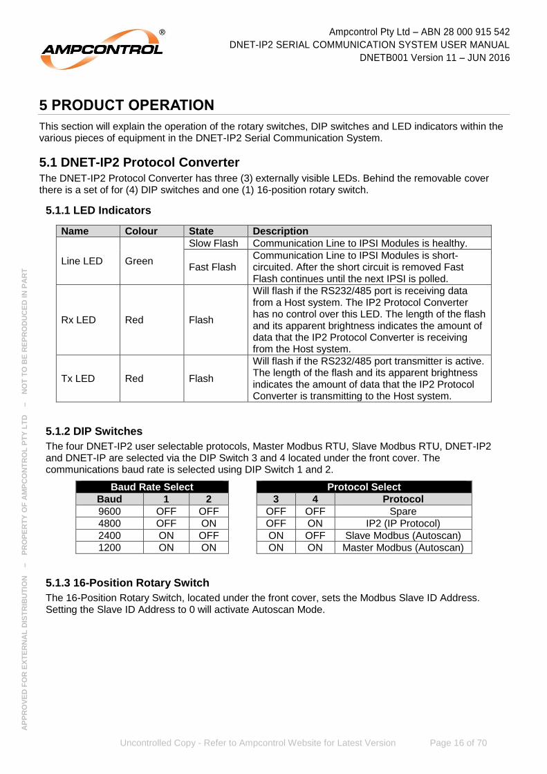
5.1 DNET-IP2 Protocol Converter The DNET-IP2 Protocol Converter has three (3) externally visible LEDs. Behind the removable cover there is a set of for (4) DIP switches and one (1) 16-position rotary switch.
5.1.1 LED Indicators
Name Colour State Description
Line LED Green
Slow Flash Communication Line to IPSI Modules is healthy.
Fast Flash Communication Line to IPSI Modules is short-circuited. After the short circuit is removed Fast Flash continues until the next IPSI is polled.
Rx LED Red Flash
Will flash if the RS232/485 port is receiving data from a Host system. The IP2 Protocol Converter has no control over this LED. The length of the flash and its apparent brightness indicates the amount of data that the IP2 Protocol Converter is receiving from the Host system.
Tx LED Red Flash
Will flash if the RS232/485 port transmitter is active. The length of the flash and its apparent brightness indicates the amount of data that the IP2 Protocol Converter is transmitting to the Host system.
5.1.2 DIP Switches
The four DNET-IP2 user selectable protocols, Master Modbus RTU, Slave Modbus RTU, DNET-IP2 and DNET-IP are selected via the DIP Switch 3 and 4 located under the front cover. The communications baud rate is selected using DIP Switch 1 and 2.
Baud Rate Select Protocol Select
Baud 1 2 3 4 Protocol
9600 OFF OFF OFF OFF Spare
4800 OFF ON OFF ON IP2 (IP Protocol)
2400 ON OFF ON OFF Slave Modbus (Autoscan)
1200 ON ON ON ON Master Modbus (Autoscan)
5.1.3 16-Position Rotary Switch
The 16-Position Rotary Switch, located under the front cover, sets the Modbus Slave ID Address. Setting the Slave ID Address to 0 will activate Autoscan Mode.

Ampcontrol Pty Ltd – ABN 28 000 915 542
DNET-IP2 SERIAL COMMUNICATION SYSTEM USER MANUAL
DNETB001 Version 11 – JUN 2016
Uncontrolled Copy - Refer to Ampcontrol Website for Latest Version Page 17 of 70
AP
PR
OV
ED
FO
R E
XT
ER
NA
L D
IST
RIB
UT
ION
– P
RO
PE
RT
Y O
F A
MP
CO
NT
RO
L P
TY
LT
D
–
NO
T T
O B
E R
EP
RO
DU
CE
D IN
PA
RT
5.2 DNET Power Supply The DNET Power Supply has one (1) externally visible LED.
Name Colour State Description
Output LED Red On
Power supply is operating and output power is available.
Off Power supply is off.
5.3 IPSI-IPA The IPSI-IPA has two (2) externally visible LEDs. Behind the removable cover there is one (1) 16-position rotary switch.
5.3.1 LED Indicators
Name Colour State Description
Line LED Yellow Flash Operation depends upon the selected user protocol (see Section 6).
IPA LED Green Flash Flashes each time a block of data is being read from the Integrated Protection Relay
5.3.2 Selector Switch
The 16-Position Rotary Switch, located under the front cover, sets the IPSI Address of the module. Each IPSI that is connected to must have a unique address to avoid data collisions. The IPSI Address can be set in the range of 1 to 15. Setting the IPSI Address to 0 will set the IPSI to offline.
NOTE
If the Modbus Slave Protocol is being used, changing the IPSI Address will change the Modbus address range for that IPSI Module. See
Section 6.2 for more details
5.4 IPSI-D The IPSI-D has two (2) externally visible LEDs. Behind the removable cover there is one (1) 16-position rotary switch.
5.4.1 LED Indicators
Name Colour State Description
Line LED Green Flash Operation depends upon the selected user protocol (see Section 6).
IPD LED Red Flash Flashes each time a block of data is being read from the Integrated Protection Relay
5.4.2 Selector Switch
The 16-Position Rotary Switch, located under the front cover, sets the IPSI Address of the module. Each IPSI that is connected to must have a unique address to avoid data collisions. The IPSI Address can be set in the range of 1 to 15. Setting the IPSI Address to 0 will set the IPSI to offline.
NOTE
If the Modbus Slave Protocol is being used, changing the IPSI Address will change the Modbus address range for that IPSI Module. See
Section 6.2 for more details
Ampcontrol Pty Ltd – ABN 28 000 915 542
DNET-IP2 SERIAL COMMUNICATION SYSTEM USER MANUAL
DNETB001 Version 11 – JUN 2016
Uncontrolled Copy - Refer to Ampcontrol Website for Latest Version Page 18 of 70
AP
PR
OV
ED
FO
R E
XT
ER
NA
L D
IST
RIB
UT
ION
– P
RO
PE
RT
Y O
F A
MP
CO
NT
RO
L P
TY
LT
D
–
NO
T T
O B
E R
EP
RO
DU
CE
D IN
PA
RT
6 COMMUNICATION PROTOCOLS
The DNET-IP2 Protocol Converter has four user selectable protocols:
Master Modbus RTU
Slave Modbus RTU
DNET-IP2
DNET-IP
These protocols are selected using the dip switches under the front cover of the DNET-IP2 Protocol Converter (see Section 5.1.2).
6.1 Master Modbus RTU
Master Modbus RTU mode is selected by placing switches 3 and 4 to the ‘ON’ position on the Dip Switch.
Switches 1 and 2 of Dip Switch set the Baud Rate. The available rates are 1200, 2400, 4800 and 9600.
In Master Modbus Mode the DNET-IP2 Protocol Converter scans for IPSI Modules and sends the data to a Slave Modbus Device. The module data is written to the Slave Modbus Device using command 16, ‘Write Multiple Holding Registers’ using Modbus RTU Protocol, even parity, 8 bit data with 1 stop bit. Data is written to the Slave ID address at the Slave Data Address.
The Slave ID Address 1 to 15 is selected via the Rotary Switch. If the Slave ID address is zero then the Autoscan Mode is selected.
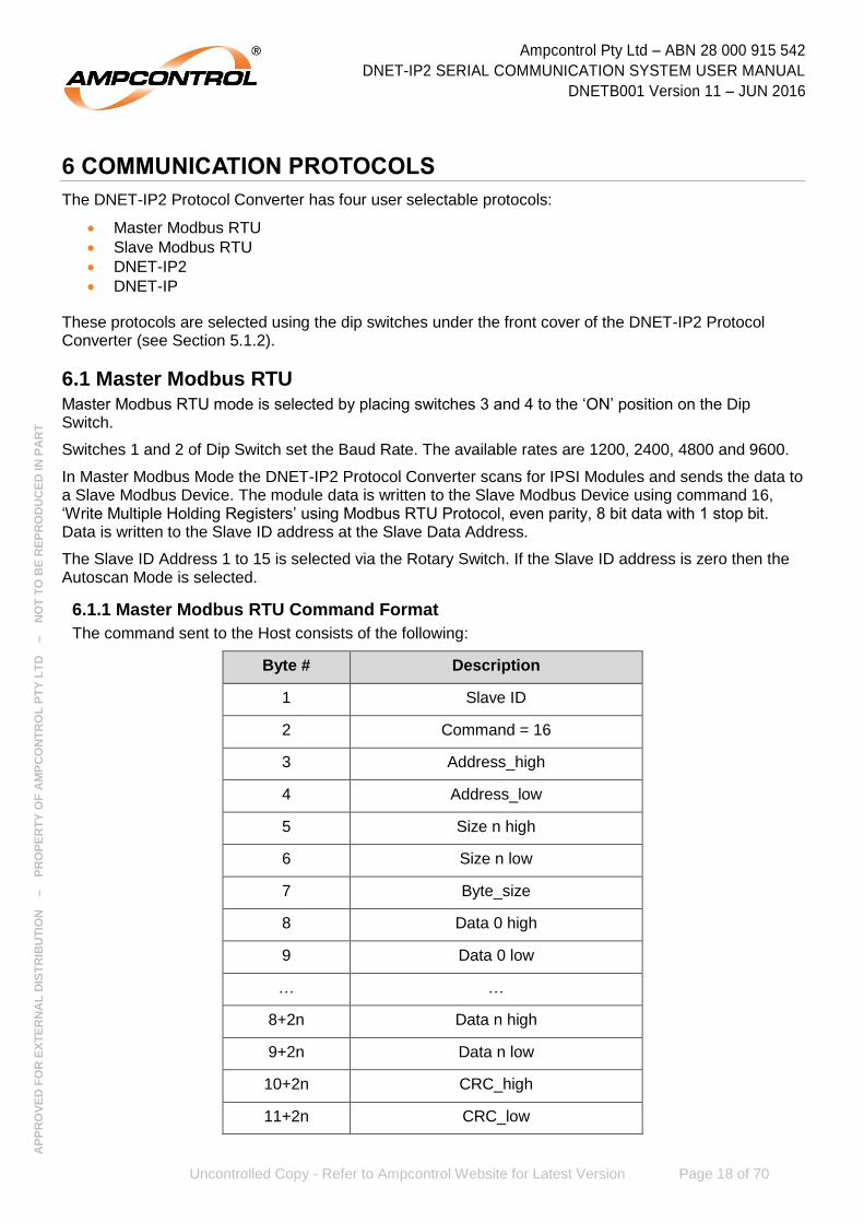
6.1.1 Master Modbus RTU Command Format
The command sent to the Host consists of the following:
Byte # Description
1 Slave ID
2 Command = 16
3 Address_high
4 Address_low
5 Size n high
6 Size n low
7 Byte_size
8 Data 0 high
9 Data 0 low
… …
8+2n Data n high
9+2n Data n low
10+2n CRC_high
11+2n CRC_low
Ampcontrol Pty Ltd – ABN 28 000 915 542
DNET-IP2 SERIAL COMMUNICATION SYSTEM USER MANUAL
DNETB001 Version 11 – JUN 2016
Uncontrolled Copy - Refer to Ampcontrol Website for Latest Version Page 19 of 70
AP
PR
OV
ED
FO
R E
XT
ER
NA
L D
IST
RIB
UT
ION
– P
RO
PE
RT
Y O
F A
MP
CO
NT
RO
L P
TY
LT
D
–
NO
T T
O B
E R
EP
RO
DU
CE
D IN
PA
RT
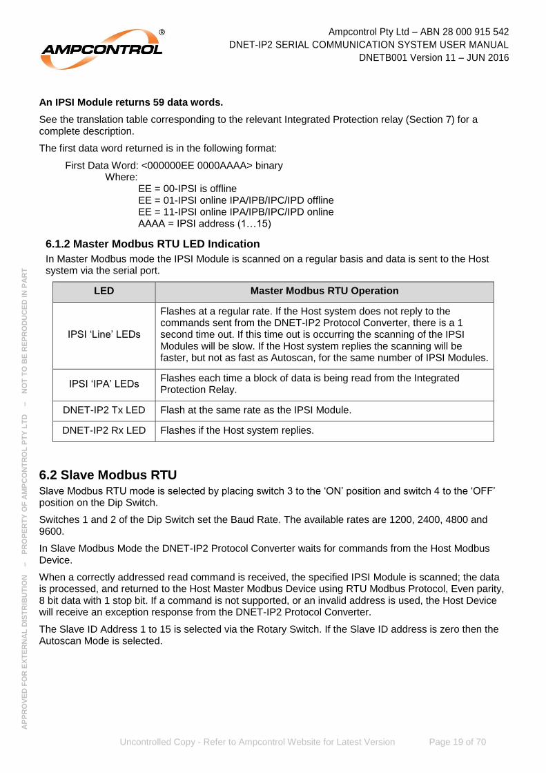
An IPSI Module returns 59 data words.
See the translation table corresponding to the relevant Integrated Protection relay (Section 7) for a complete description.
The first data word returned is in the following format:
First Data Word: <000000EE 0000AAAA> binary Where:
EE = 00-IPSI is offline EE = 01-IPSI online IPA/IPB/IPC/IPD offline EE = 11-IPSI online IPA/IPB/IPC/IPD online AAAA = IPSI address (1…15)
6.1.2 Master Modbus RTU LED Indication
In Master Modbus mode the IPSI Module is scanned on a regular basis and data is sent to the Host system via the serial port.
LED Master Modbus RTU Operation
IPSI ‘Line’ LEDs
Flashes at a regular rate. If the Host system does not reply to the commands sent from the DNET-IP2 Protocol Converter, there is a 1 second time out. If this time out is occurring the scanning of the IPSI Modules will be slow. If the Host system replies the scanning will be faster, but not as fast as Autoscan, for the same number of IPSI Modules.
IPSI ‘IPA’ LEDs Flashes each time a block of data is being read from the Integrated Protection Relay.
DNET-IP2 Tx LED Flash at the same rate as the IPSI Module.
DNET-IP2 Rx LED Flashes if the Host system replies.
6.2 Slave Modbus RTU Slave Modbus RTU mode is selected by placing switch 3 to the ‘ON’ position and switch 4 to the ‘OFF’ position on the Dip Switch.
Switches 1 and 2 of the Dip Switch set the Baud Rate. The available rates are 1200, 2400, 4800 and 9600.
In Slave Modbus Mode the DNET-IP2 Protocol Converter waits for commands from the Host Modbus Device.
When a correctly addressed read command is received, the specified IPSI Module is scanned; the data is processed, and returned to the Host Master Modbus Device using RTU Modbus Protocol, Even parity, 8 bit data with 1 stop bit. If a command is not supported, or an invalid address is used, the Host Device will receive an exception response from the DNET-IP2 Protocol Converter.
The Slave ID Address 1 to 15 is selected via the Rotary Switch. If the Slave ID address is zero then the Autoscan Mode is selected.

Ampcontrol Pty Ltd – ABN 28 000 915 542
DNET-IP2 SERIAL COMMUNICATION SYSTEM USER MANUAL
DNETB001 Version 11 – JUN 2016
Uncontrolled Copy - Refer to Ampcontrol Website for Latest Version Page 20 of 70
AP
PR
OV
ED
FO
R E
XT
ER
NA
L D
IST
RIB
UT
ION
– P
RO
PE
RT
Y O
F A
MP
CO
NT
RO
L P
TY
LT
D
–
NO
T T
O B
E R
EP
RO
DU
CE
D IN
PA
RT
6.2.1 Slave Modbus RTU Commands
The IP2 Protocol Converter supports the following commands:
CMD=3 Read Holding Registers
CMD=4 Read Input Registers
CMD=6 Write Holding Register
CMD=7 Read Exception Status
CMD=16 Write Multiple Holding Registers
CMD=17 Read Slave ID
The IPSI Address of the IPSI Module affects the Modbus Address that the information can be accessed from. The below table should be referred to, in conjunction with the relevant Translation table (Section 7) for the Integrated Protection relay that is in use.
IPSI-IPA or IPSI-D Address
Modbus Address Description
0000-000F Read/Write
1 0100 – 013F Read
2 0200 – 023F Read
3 0300 – 033F Read
4 0400 – 043F Read
5 0500 – 053F Read
6 0600 – 063F Read
7 0700 – 073F Read
8 0800 – 083F Read
9 0900 – 093F Read
10 0A00 – 0A3F Read
11 0B00 – 0B3F Read
12 0C00 – 0C3F Read
13 0D00 – 0D3F Read
14 0E00 – 0E3F Read
15 0F00 – 0F3F Read

Ampcontrol Pty Ltd – ABN 28 000 915 542
DNET-IP2 SERIAL COMMUNICATION SYSTEM USER MANUAL
DNETB001 Version 11 – JUN 2016
Uncontrolled Copy - Refer to Ampcontrol Website for Latest Version Page 21 of 70
AP
PR
OV
ED
FO
R E
XT
ER
NA
L D
IST
RIB
UT
ION
– P
RO
PE
RT
Y O
F A
MP
CO
NT
RO
L P
TY
LT
D
–
NO
T T
O B
E R
EP
RO
DU
CE
D IN
PA
RT
Read commands must not exceed 64 words.
IPSI Module returns 59 data words but any size from 1 to 64 is valid. Data beyond word 59 will be random. See the translation table for a complete description. The first data word returned is in the following format:
First Data Word: <000000EE 0000AAAA> binary Where:
EE = 00-IPSI is offline EE = 01-IPSI online IPA/IPB/IPC offline EE = 11-IPSI online IPA/IPB/IPC online AAAA = IPSI address (1…15)
6.2.2 Slave Modbus RTU LED Indication
In Slave Modbus mode the IPSI Modules are scanned only on direct request from the Host system.
LED Master Modbus RTU Operation
IPSI ‘Line’ LEDs Flashes only if the IPSI Module is requested from the Master Host system.
IPSI ‘IPA’ LEDs Flashes each time a block of data is being read from the Integrated Protection relay.
DNET-IP2 Tx LED Flashes every time a command is received from the Master Host system.
DNET-IP2 Rx LED Flashes whenever the DNET-IP2 Protocol Converter responds to a Master Host command.
6.3 Modbus Autoscan Autoscan is selected in either Modbus Master or Slave Protocol by selecting ID Address = 0 to isolate a DNET-IP2 Protocol Converter from a Modbus network for the purpose of fault finding.
In this mode the DNET-IP2 Protocol Converter sequentially scans for IPSI Modules connected to the L1 communication line regardless of any host commands. The serial communication port is disabled, but the Rx LED will still flash if data is received from a Host Device.
6.3.1 Modbus Autoscan LED Indication
In Autoscan the IPSI Modules are scanned on a regular basis but no data is transferred to the serial port.
LED Master Modbus RTU Operation
IPSI ‘Line’ LEDs Flashes at a regular rate.
IPSI ‘IPA’ LEDs Flashes each time a block of data is being read from the Integrated Protection relay.
DNET-IP2 Tx LED Should not flash.
DNET-IP2 Rx LED Flashes if data is being received, but this data is ignored in Autoscan Mode.

Ampcontrol Pty Ltd – ABN 28 000 915 542
DNET-IP2 SERIAL COMMUNICATION SYSTEM USER MANUAL
DNETB001 Version 11 – JUN 2016
Uncontrolled Copy - Refer to Ampcontrol Website for Latest Version Page 22 of 70
AP
PR
OV
ED
FO
R E
XT
ER
NA
L D
IST
RIB
UT
ION
– P
RO
PE
RT
Y O
F A
MP
CO
NT
RO
L P
TY
LT
D
–
NO
T T
O B
E R
EP
RO
DU
CE
D IN
PA
RT
6.4 IP Protocol (IP2 Protocol Mode with Slave ID Address = 0) IP Protocol mode is selected by placing switch 3 to the ‘OFF’ position and switch 4 to the ‘ON’ position on the Dip Switch and selecting Slave ID Address = 0 on the rotary switch.
Switches 1 and 2 of the Dip Switch set the Baud Rate. The available rates are 1200, 2400, 4800 and 9600.
In IP Protocol Mode the DNET-IP2 Protocol Converter waits for a command from the Host system. When a correctly addressed command is received, the corresponding IPSI Module is scanned; its data is processed, and returned to the Host Device in a block of 64 bytes. There are no write commands available.
6.4.1 IP Protocol Commands
The Host system sends a single byte command:
<IPSI-ID> (no CR or LF)
Where:
<IPSI-ID> is ASCII ‘A’ to ‘O’ = IPSI-ID address 1 to 15.
The response is identical to the IP2 protocol description in the following section.
6.5 IP2 Protocol (IP2 Protocol Mode with Slave ID Address = 1…8) IP2 Protocol mode is selected by placing switch 3 to the ‘OFF’ position and switch 4 to the ‘ON’ position on the Dip Switch and selecting Slave ID = 1…8 on the rotary switch.
Switches 1 and 2 of the Dip Switch set the Baud Rate. The available rates are 1200, 2400, 4800 and 9600.
In IP2 Protocol Mode the DNET-IP2 Protocol Converter waits for a command from the Host system. When a correctly addressed command is received the corresponding IPSI Module is scanned, its data is processed, and returned to the Host Device in a block of 64 bytes. There are no write commands available.
The IP2 Protocol is a multi-drop protocol where a maximum of eight (8) DNET-IP2 Protocol Converters can be addressed on the same RS485/RS422 network (See Drawing DNETE011, in Appendix A).
The IP2 Protocol Mode is a very low overhead protocol and is an Ampcontrol proprietary protocol. It is designed for implementation in ‘ladder logic drivers’ in PLC’s where processing is limited.
The Slave ID Address 1 to 8 is selected via the Rotary Switch. If the Slave ID address is zero then the IP Protocol Mode is selected.
Ampcontrol Pty Ltd – ABN 28 000 915 542
DNET-IP2 SERIAL COMMUNICATION SYSTEM USER MANUAL
DNETB001 Version 11 – JUN 2016
Uncontrolled Copy - Refer to Ampcontrol Website for Latest Version Page 23 of 70
AP
PR
OV
ED
FO
R E
XT
ER
NA
L D
IST
RIB
UT
ION
– P
RO
PE
RT
Y O
F A
MP
CO
NT
RO
L P
TY
LT
D
–
NO
T T
O B
E R
EP
RO
DU
CE
D IN
PA
RT
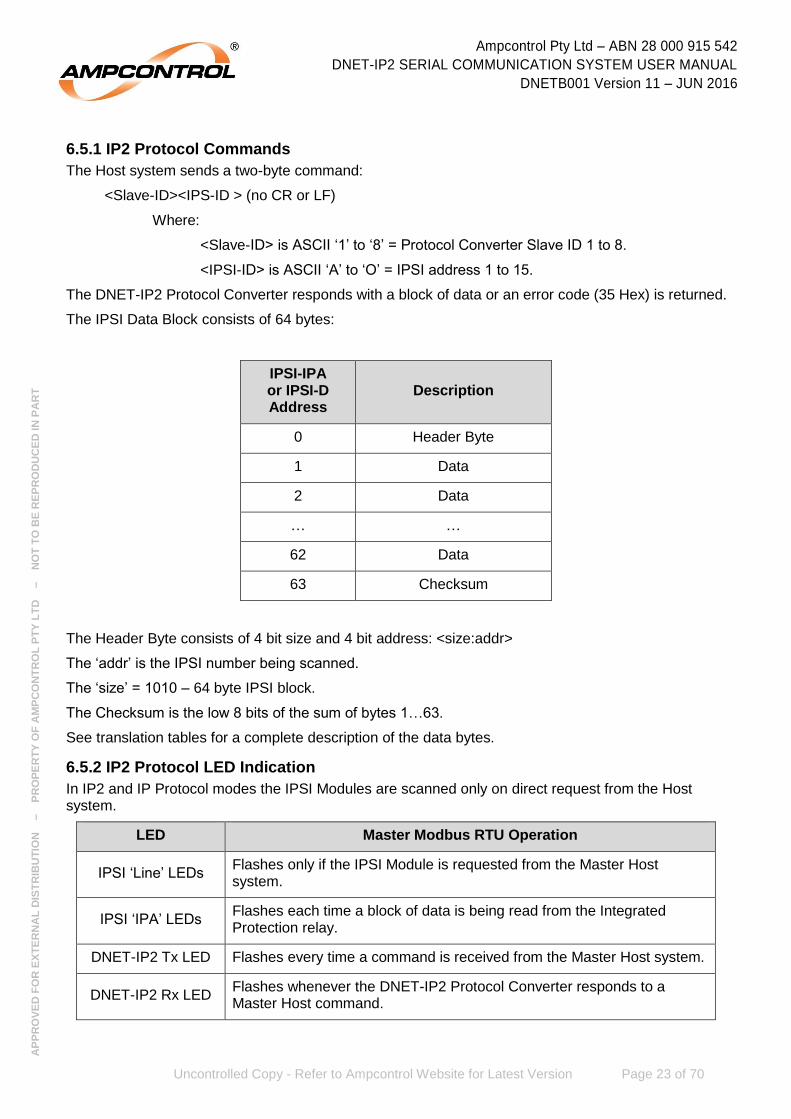
6.5.1 IP2 Protocol Commands
The Host system sends a two-byte command:
<Slave-ID><IPS-ID > (no CR or LF)
Where:
<Slave-ID> is ASCII ‘1’ to ‘8’ = Protocol Converter Slave ID 1 to 8.
<IPSI-ID> is ASCII ‘A’ to ‘O’ = IPSI address 1 to 15.
The DNET-IP2 Protocol Converter responds with a block of data or an error code (35 Hex) is returned.
The IPSI Data Block consists of 64 bytes:
IPSI-IPA or IPSI-D Address
Description
0 Header Byte
1 Data
2 Data
… …
62 Data
63 Checksum
The Header Byte consists of 4 bit size and 4 bit address: <size:addr>
The ‘addr’ is the IPSI number being scanned.
The ‘size’ = 1010 – 64 byte IPSI block.
The Checksum is the low 8 bits of the sum of bytes 1…63.
See translation tables for a complete description of the data bytes.
6.5.2 IP2 Protocol LED Indication
In IP2 and IP Protocol modes the IPSI Modules are scanned only on direct request from the Host system.
LED Master Modbus RTU Operation
IPSI ‘Line’ LEDs Flashes only if the IPSI Module is requested from the Master Host system.
IPSI ‘IPA’ LEDs Flashes each time a block of data is being read from the Integrated Protection relay.
DNET-IP2 Tx LED Flashes every time a command is received from the Master Host system.
DNET-IP2 Rx LED Flashes whenever the DNET-IP2 Protocol Converter responds to a Master Host command.

Ampcontrol Pty Ltd – ABN 28 000 915 542
DNET-IP2 SERIAL COMMUNICATION SYSTEM USER MANUAL
DNETB001 Version 11 – JUN 2016
Uncontrolled Copy - Refer to Ampcontrol Website for Latest Version Page 24 of 70
AP
PR
OV
ED
FO
R E
XT
ER
NA
L D
IST
RIB
UT
ION
– P
RO
PE
RT
Y O
F A
MP
CO
NT
RO
L P
TY
LT
D
–
NO
T T
O B
E R
EP
RO
DU
CE
D IN
PA
RT
7 TRANSLATION TABLES
NOTE
Typically “????” indicates that the reading is unknown as the relay is not yet configured. This is not cause for concern and does not require
any action by the operator.
7.1 IPD 11kV Translation TableModbus
Word IP
Byte IPD 11kV Translation Table
Description
N/A 0 IPSI Address
Bits 0..3 = IPSI Address (Range 1-15)
1 N/A
IPSI Address
Bits 0..3 = IPSI Address (Range 1-15) Bit 8 = IPSI Online Bit 9 = IPD Online
N/A 1
Digital Inputs (DIG_INPUTS)
Bit 0 = Reserved
Bit 1 = IPSI to IPD Comms OK
Bit 2 = Fan Interlock Read
Bit 3 = IPD Stop digital Input
Bit 4 = IPD Reset Digital Input
Bit 5 = IPD Lock Digital Input
Bit 6 = IPD MCI Digital Input
Bit 7 = IPD Start Digital Input
N/A 2
Opto Status (OPTOSTAT)
Bit 0 = Earth Leakage Trip
Bit 1 = Earth Continuity Trip
Bit 2 = E/F Lockout Trip
Bit 3 = Over Current Trip
Bit 4 = Short Circuit Trip
Bit 5 = Main Contactor Fail
Bit 6 = Insulation Fail
Bit 7 = Running
2 N/A
Opto Status/Digital Inputs
(OPTOSTAT+DIG_INPUTS)
Bit 0 = Earth leakage Trip
Bit 1 = Earth Continuity Trip
Bit 2 = Earth Fault Lockout
Bit 3 = Overload
Bit 4 = Short circuit
Bit 5 = MCF Bit
Bit 6 = Insulation Fail
Bit 7 = Outlet Run
Bit 8 = Reserved
Bit 9 = IPSI to IPD Comms OK
Bit 10 = Fan Interlock Read
Bit 11 = IPD Stop digital Input
Bit 12 = IPD Reset Digital Input
Bit 13 = IPD Lock Digital Input
Bit 14 = IPD MCI Digital Input
Bit 15 = IPD Start Digital Input
3 3 Earth Leakage Current (EL_CUR)
Range 0-110%
Modbus Word
IP Byte
IPD 11kV Translation Table Description
4 4
Pilot Series Resistance (PILOT_FWD)
Range 0-200%
5 5
Pilot Leakage Resistance (PILOT_REV)
Range 0-120%
6 6
Cable Fault Lockout Leakage (CFLR_LEAK)
Range 0-150%
7 7,8
A Phase Current (CUR_A_BCD_HIGH)
Range 0-999%
8 9,10
B Phase Current (CUR_B_BCD_HIGH)
Range 0-999%
9 11,12
C Phase Current (CUR_C_BCD_HIGH)
Range 0-999%
10 13
Over Current Trip
(OC TRIP_HIGH)
Range 0-120%
11 14 Current Balance (CURRENT_BAL)
Range 0-100%
12 15 A Phase Volts (VOLTS_A)
Range 0-120%
13 16 B Phase Volts (VOLTS_B)
Range 0-120%
14 17 C Phase Volts (VOLTS_C)
Range 0-120%
15 18
Trip Status (TRIP_STAT2)
Bit 0 = IPD Memory Error
Bit 1 = RTU Memory Error
Bit 2 = Trip - RTU Offline
Bit 3 = Stopped - RTU PTC
Bit 4 = Stopped - RTU
Bit 5 = I Balance Trip
Bit 6 = Locked Out - Fan
Bit 7 = Stopped IPD
16 19 Reserved
17 20
IPD Software Version (IPD_SW_VER)
30 = IPD1 V01 2008 40 = IPD 11kV 01 2009 41 = IPD 11kV 02 2009

Ampcontrol Pty Ltd – ABN 28 000 915 542
DNET-IP2 SERIAL COMMUNICATION SYSTEM USER MANUAL
DNETB001 Version 11 – JUN 2016
Uncontrolled Copy - Refer to Ampcontrol Website for Latest Version Page 25 of 70
AP
PR
OV
ED
FO
R E
XT
ER
NA
L D
IST
RIB
UT
ION
– P
RO
PE
RT
Y O
F A
MP
CO
NT
RO
L P
TY
LT
D
–
NO
T T
O B
E R
EP
RO
DU
CE
D IN
PA
RT
Modbus Word
IP Byte
IPD 11kV Translation Table Description
18 21
Current Range Setting
(CUR_RANGE PARAM)
OC I Range A
1 = 60
2 = 64
3 = 68
4 = 72
5 = 76
6 = 80
7 = 84
8 = 88
9 = 92
10 = 96
11 = 100
12 = 104
13 = 108
14 = 112 15 = 116
19 22
Current Multiplier Setting
(CUR_MUL_PARAM)
OC I Mult
1 = 1/8
2 = 1/4
3 = 1/2
4 = 1
5 = 2 6 = 4
20 23
Over Current Curve Setting
(OC_CURVE_PARM)
Curve Type
1 = Vinv 2 = m-OL
21 24
Over Current Time Multiplier
(TIME_MULT_PARM)
OC Time Multiplier
1 = 0.05
2 = 0.075
3 = 0.1
4 = 0.15
5 = 0.2
6 = 0.3
7 = 0.4
8 = 0.5
9 = 0.6
10 = 0.7
11 = 0.8
12 = 1.0
13 = 0.04
14 = 0.03
15 = 0.02
16 = 0.015
17 = 0.01 18 = 0.005
Modbus Word
IP Byte
IPD 11kV Translation Table Description
22 25
Cool Multiplier Setting
(COOL_MUL_PARAM)
Cool Mult
1 = 0.2
2 = 0.3
3 = 0.4
4 = 0.5
5 = 0.8
6 = 1.0
7 = 2.0
8 = 5.0
9 = 10
10 = 20 11 = 50
23 26
Current Balance Setting
(CUR_BAL_PARAM)
Cur Bal Trip%
1 = 5
2 = 10
3 = 20
4 = 50 5 = Off
24 27
Short Circuit Setting (SHORT_CCT_PARAM)
SC I Trip Mult
1 = 3.0
2 = 3.5
3 = 4.0
4 = 4.5
5 = 5.0
6 = 5.5
7 = 6.0
8 = 6.5
9 = 7.0
10 = 7.5
11 = 8.0
12 = 8.5
13 = 9.0
14 = 9.5 15 = 10.0
25 28
Short Circuit Trip Time Setting
(SC_TRP_TM_PARAM)
SC Trip Time – mS
1 = 20
2 = 40
3 = 60
4 = 80
5 = 100
6 = 120 7 = 160

Ampcontrol Pty Ltd – ABN 28 000 915 542
DNET-IP2 SERIAL COMMUNICATION SYSTEM USER MANUAL
DNETB001 Version 11 – JUN 2016
Uncontrolled Copy - Refer to Ampcontrol Website for Latest Version Page 26 of 70
AP
PR
OV
ED
FO
R E
XT
ER
NA
L D
IST
RIB
UT
ION
– P
RO
PE
RT
Y O
F A
MP
CO
NT
RO
L P
TY
LT
D
–
NO
T T
O B
E R
EP
RO
DU
CE
D IN
PA
RT
Modbus Word
IP Byte
IPD 11kV Translation Table Description
26 29
Short Circuit Output Relay Selection
(SC_OUT_PARAM)
SC Relay)
1 = CBR 2 = MCR
27 30
Earth Leakage Sensitivity Setting
(EL_SENS)
EL Sens – mA
1 < 500
2 < 750
3 < 1000
4 < 1250
5 < 1500
6 < 1750
7 < 2000
8 < 2250
9 < 2500
28 31
Earth Leakage Trip time Setting
(EL_TIME)
EL Time – ms
1 = ins
2 = 100
3 = 150
4 = 190
5 = 230
6 = 270
7 = 310
8 = 350
9 = 390
10 = 430
11 = 470
29 32
Pilot Mode Selection (PILOT MODE)
Pilot Type
1 = RTU
2 = Diode
30 33
CCM Selection (VOLTS_SELECT)
EFLO-11kV
1 = YES 2 = None
31 34
Back EMF Timer Selection
(B_EMF_TIME)
B emf Time – sec
1 = 2
2 = 5
3 = 10
4 = 15 5 = 20
Modbus Word
IP Byte
IPD 11kV Translation Table Description
32 35
Insulation Test Trip Setting
(MEG_LEVEL)
Ins. TstT - MΩ
1 = 15
2 = 20
3 = 25
4 = 30
5 = 35
6 = 50
7 = 80
8 = 100
9 = None
33 36
Earth Continuity Trip Level (was RL3)
(ECLEVEL_ADJ)
EC Resistance - Ω
1 = 10
2 = 15
3 = 20
4 = 25
5 = 30 6 = 45
34 37
Machine Type Setting
(MACHINE_TYPE)
1 = Belt - Conveyor Belt
2 = SHRr – Shearer
3 = S-Ld - Stage Loader
4 = Hpmp - Hydraulic Pump
5 = Wpmp - Water Pump
6 = cMnr - Continuous Miner
7 = SCar - Shuttle Car
8 = Bk/F - Breaker Feeder
9 = Crsh – Crusher
10 = Fan
11 = DCB
12 = Blank
13 = iFan - Interlocking Fan
14 = AFCm - AFC Main Gate
15 = AFCt - AFC Tail Gate
16 = M-BE -Moveable Boot End
17 = Bolt – Bolter
18 = HRMr - Hard Rock Miner
19 = Winc – Winch
20 = J-bo - Jumbo
21 = bBelt - Belly Belt
22 = Stak - Stacker
23 = aCar Add-Car
24 = IGG - Inert Gas
25 = tBlt - Transfer Belt 26 = Dplg - Dummy Plug
35 38
Machine Number Setting (MACHINE_NUM)
1 – 40 Sets the RTU MC Number
Ampcontrol Pty Ltd – ABN 28 000 915 542
DNET-IP2 SERIAL COMMUNICATION SYSTEM USER MANUAL
DNETB001 Version 11 – JUN 2016
Uncontrolled Copy - Refer to Ampcontrol Website for Latest Version Page 27 of 70
AP
PR
OV
ED
FO
R E
XT
ER
NA
L D
IST
RIB
UT
ION
– P
RO
PE
RT
Y O
F A
MP
CO
NT
RO
L P
TY
LT
D
–
NO
T T
O B
E R
EP
RO
DU
CE
D IN
PA
RT
Modbus Word
IP Byte
IPD 11kV Translation Table Description
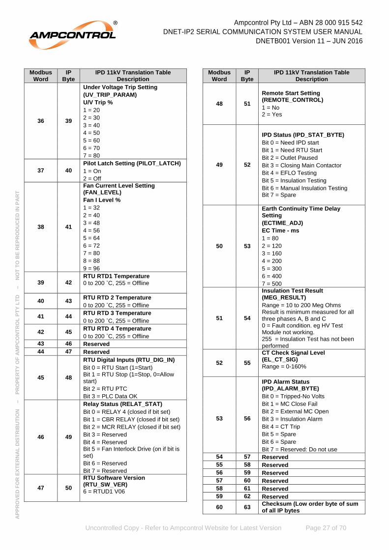
36 39
Under Voltage Trip Setting
(UV_TRIP_PARAM)
U/V Trip %
1 = 20
2 = 30
3 = 40
4 = 50
5 = 60
6 = 70
7 = 80
37 40
Pilot Latch Setting (PILOT_LATCH)
1 = On
2 = Off
38 41
Fan Current Level Setting (FAN_LEVEL)
Fan I Level %
1 = 32
2 = 40
3 = 48
4 = 56
5 = 64
6 = 72
7 = 80
8 = 88
9 = 96
39 42 RTU RTD1 Temperature
0 to 200 ˚C, 255 = Offline
40 43 RTU RTD 2 Temperature
0 to 200 ˚C, 255 = Offline
41 44 RTU RTD 3 Temperature
0 to 200 ˚C, 255 = Offline
42 45 RTU RTD 4 Temperature
0 to 200 ˚C, 255 = Offline
43 46 Reserved
44 47 Reserved
45 48
RTU Digital Inputs (RTU_DIG_IN)
Bit 0 = RTU Start (1=Start) Bit 1 = RTU Stop (1=Stop, 0=Allow start)
Bit 2 = RTU PTC
Bit 3 = PLC Data OK
46 49
Relay Status (RELAT_STAT)
Bit 0 = RELAY 4 (closed if bit set)
Bit 1 = CBR RELAY (closed if bit set)
Bit 2 = MCR RELAY (closed if bit set)
Bit 3 = Reserved
Bit 4 = Reserved Bit 5 = Fan Interlock Drive (on if bit is set)
Bit 6 = Reserved
Bit 7 = Reserved
47 50
RTU Software Version (RTU_SW_VER)
6 = RTUD1 V06
Modbus Word
IP Byte
IPD 11kV Translation Table Description
48 51
Remote Start Setting (REMOTE_CONTROL)
1 = No 2 = Yes
49 52
IPD Status (IPD_STAT_BYTE)
Bit 0 = Need IPD start
Bit 1 = Need RTU Start
Bit 2 = Outlet Paused
Bit 3 = Closing Main Contactor
Bit 4 = EFLO Testing
Bit 5 = Insulation Testing
Bit 6 = Manual Insulation Testing Bit 7 = Spare
50 53
Earth Continuity Time Delay Setting
(ECTIME_ADJ)
EC Time - ms
1 = 80
2 = 120
3 = 160
4 = 200
5 = 300
6 = 400
7 = 500
51 54
Insulation Test Result (MEG_RESULT)
Range = 10 to 200 Meg Ohms Result is minimum measured for all three phases A, B and C 0 = Fault condition. eg HV Test Module not working. 255 = Insulation Test has not been performed
52 55
CT Check Signal Level (EL_CT_SIG)
Range = 0-160%
IPD Alarm Status (IPD_ALARM_BYTE)
53 56
Bit 0 = Tripped-No Volts
Bit 1 = MC Close Fail
Bit 2 = External MC Open
Bit 3 = Insulation Alarm
Bit 4 = CT Trip
Bit 5 = Spare
Bit 6 = Spare
Bit 7 = Reserved: Do not use
54 57 Reserved
55 58 Reserved
56 59 Reserved
57 60 Reserved
58 61 Reserved
59 62 Reserved
60 63 Checksum (Low order byte of sum of all IP bytes

Ampcontrol Pty Ltd – ABN 28 000 915 542
DNET-IP2 SERIAL COMMUNICATION SYSTEM USER MANUAL
DNETB001 Version 11 – JUN 2016
Uncontrolled Copy - Refer to Ampcontrol Website for Latest Version Page 28 of 70
AP
PR
OV
ED
FO
R E
XT
ER
NA
L D
IST
RIB
UT
ION
– P
RO
PE
RT
Y O
F A
MP
CO
NT
RO
L P
TY
LT
D
–
NO
T T
O B
E R
EP
RO
DU
CE
D IN
PA
RT
7.2 IPD Translation TableModbus
Word IP
Byte IPD Translation Table
Description
N/A 0 IPSI Address
Bits 0..3 = IPSI Address (Range 1-15)
1 N/A
IPSI Address
Bits 0..3 = IPSI Address (Range 1-15) Bit 8 = IPSI Online Bit 9 = IPD Online
N/A 1
Digital Inputs (DIG_INPUTS)
Bit 0 = Reserved Bit 1 = IPSI to IPD Comms OK Bit 2 = Fan Interlock Read Bit 3 = IPD Stop digital Input Bit 4 = IPD Reset Digital Input Bit 5 = IPD Lock Digital Input Bit 6 = IPD MCI Digital Input Bit 7 = IPD Start Digital Input
N/A 2
Opto Status (OPTOSTAT)
Bit 0 = Earth Leakage Trip Bit 1 = Earth Continuity Trip Bit 2 = E/F Lockout Trip Bit 3 = Over Current Trip Bit 4 = Short Circuit Trip Bit 5 = Main Contactor Fail Bit 6 = Insulation Fail Bit 7 = Running
2 N/A
Opto Status/Digital Inputs (OPTOSTAT+DIG_INPUTS)
Bit 0 = Earth leakage Trip Bit 1 = Earth Continuity Trip Bit 2 = Earth Fault Lockout Bit 3 = Overload Bit 4 = Short circuit Bit 5 = MCF Bit Bit 6 = Insulation Fail Bit 7 = Outlet Run Bit 8 = Reserved Bit 9 = IPSI to IPD Comms OK Bit 10 = Fan Interlock Read Bit 11 = IPD Stop digital Input Bit 12 = IPD Reset Digital Input Bit 13 = IPD Lock Digital Input Bit 14 = IPD MCI Digital Input Bit 15 = IPD Start Digital Input
3 3 Earth Leakage Current (EL_CUR)
Range 0-100%
4 4 Pilot Series Resistance (PILOT_FWD)
Range 0-200%
5 5 Pilot Leakage Resistance (PILOT_REV)
Range 0-120%
6 6 Cable Fault Lockout Leakage (CFLR_LEAK)
Range 0-100%
7 7,8
A Phase Current (CUR_A_BCD_HIGH)
Range 0-999%
Modbus Word
IP Byte
IPD Translation Table Description
8 9,10
B Phase Current (CUR_B_BCD_HIGH)
Range 0-999%
9 11,12
C Phase Current (CUR_C_BCD_HIGH)
Range 0-999%
10 13
Over Current Trip (OC TRIP_HIGH)
Range 0-120%
11 14
Current Balance (CURRENT_BAL)
Range 0-100%
12 15 A Phase Volts (VOLTS_A)
Range 0-120%
13 16 B Phase Volts (VOLTS_B)
Range 0-120%
14 17 C Phase Volts (VOLTS_C)
Range 0-120%
15 18
Trip Status (TRIP_STAT2)
Bit 0 = IPD Memory Error
Bit 1 = RTU Memory Error
Bit 2 = Trip - RTU Offline
Bit 3 = Stopped - RTU PTC
Bit 4 = Stopped - RTU
Bit 5 = I Balance Trip
Bit 6 = Locked Out - Fan
Bit 7 = Stopped IPD
16 19 Reserved
17 20
IPD Software Version (IPD_SW_VER)
30 = IPD1 V01 2008 31 = IPD1 V02 2009 32 = IPD1 V03 2013 33 = IPD1 V04 2014 34 = IPD1 V05 2015
18 21
Current Range Setting
(CUR_RANGE PARAM)
OC I Range A
0 = ???
1 = 60
2 = 64
3 = 68
4 = 72
5 = 76
6 = 80
7 = 84
8 = 88
9 = 92
10 = 96
11 = 100
12 = 104
13 = 108
14 = 112
15 = 116
Ampcontrol Pty Ltd – ABN 28 000 915 542
DNET-IP2 SERIAL COMMUNICATION SYSTEM USER MANUAL
DNETB001 Version 11 – JUN 2016
Uncontrolled Copy - Refer to Ampcontrol Website for Latest Version Page 29 of 70
AP
PR
OV
ED
FO
R E
XT
ER
NA
L D
IST
RIB
UT
ION
– P
RO
PE
RT
Y O
F A
MP
CO
NT
RO
L P
TY
LT
D
–
NO
T T
O B
E R
EP
RO
DU
CE
D IN
PA
RT
Modbus Word
IP Byte
IPD Translation Table Description
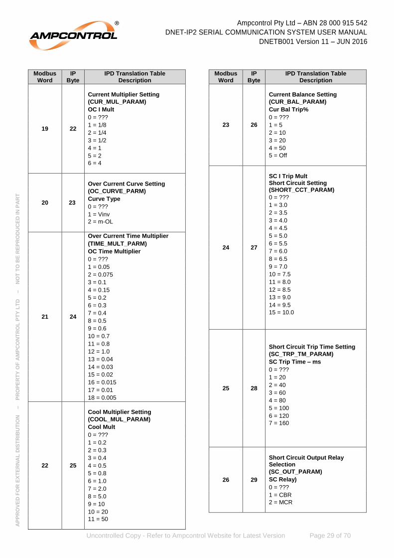
19 22
Current Multiplier Setting
(CUR_MUL_PARAM)
OC I Mult
0 = ???
1 = 1/8
2 = 1/4
3 = 1/2
4 = 1
5 = 2
6 = 4
20 23
Over Current Curve Setting
(OC_CURVE_PARM)
Curve Type
0 = ???
1 = Vinv
2 = m-OL
21 24
Over Current Time Multiplier
(TIME_MULT_PARM)
OC Time Multiplier
0 = ???
1 = 0.05
2 = 0.075
3 = 0.1
4 = 0.15
5 = 0.2
6 = 0.3
7 = 0.4
8 = 0.5
9 = 0.6
10 = 0.7
11 = 0.8
12 = 1.0
13 = 0.04
14 = 0.03
15 = 0.02
16 = 0.015
17 = 0.01
18 = 0.005
22 25
Cool Multiplier Setting
(COOL_MUL_PARAM)
Cool Mult
0 = ???
1 = 0.2
2 = 0.3
3 = 0.4
4 = 0.5
5 = 0.8
6 = 1.0
7 = 2.0
8 = 5.0
9 = 10
10 = 20
11 = 50
Modbus Word
IP Byte
IPD Translation Table Description
23 26
Current Balance Setting
(CUR_BAL_PARAM)
Cur Bal Trip%
0 = ???
1 = 5
2 = 10
3 = 20
4 = 50
5 = Off
24 27
SC I Trip Mult Short Circuit Setting (SHORT_CCT_PARAM)
0 = ???
1 = 3.0
2 = 3.5
3 = 4.0
4 = 4.5
5 = 5.0
6 = 5.5
7 = 6.0
8 = 6.5
9 = 7.0
10 = 7.5
11 = 8.0
12 = 8.5
13 = 9.0
14 = 9.5
15 = 10.0
25 28
Short Circuit Trip Time Setting
(SC_TRP_TM_PARAM)
SC Trip Time – ms
0 = ???
1 = 20
2 = 40
3 = 60
4 = 80
5 = 100
6 = 120
7 = 160
26 29
Short Circuit Output Relay Selection
(SC_OUT_PARAM)
SC Relay)
0 = ???
1 = CBR
2 = MCR

Ampcontrol Pty Ltd – ABN 28 000 915 542
DNET-IP2 SERIAL COMMUNICATION SYSTEM USER MANUAL
DNETB001 Version 11 – JUN 2016
Uncontrolled Copy - Refer to Ampcontrol Website for Latest Version Page 30 of 70
AP
PR
OV
ED
FO
R E
XT
ER
NA
L D
IST
RIB
UT
ION
– P
RO
PE
RT
Y O
F A
MP
CO
NT
RO
L P
TY
LT
D
–
NO
T T
O B
E R
EP
RO
DU
CE
D IN
PA
RT
Modbus Word
IP Byte
IPD Translation Table Description
27 30
Earth Leakage Sensitivity Setting
(EL_SENS)
EL Sens – mA
0 = ???
1 < 100
2 < 150
3 < 200
4 < 250
5 < 300
6 < 350
7 < 400
8 < 450
9 < 500
28 31
Earth Leakage Trip time Setting
(EL_TIME)
EL Time – ms
0 = ???
1 = ins
2 = 100
3 = 150
4 = 190
5 = 230
6 = 270
7 = 310
8 = 350
9 = 390
10 = 430
11 = 470
29 32
Pilot Mode Selection
(PILOT MODE)
Pilot Type
0 = ???
1 = RTU
2 = Diode
30 33
CCM Selection
(VOLTS_SELECT)
(EFLO: CCM Volts
0 = ???
1 = D415
2 = D1k
3 = D3k3
4 = A415
5 = A1k
6 = A3k3
7 = A110
8 = None
31 34
Back EMF Timer Selection
(B_EMF_TIME)
B emf Time – Sec
0 = ???
1 = 2
2 = 5
3 = 10
4 = 15
5 = 20
Modbus Word
IP Byte
IPD Translation Table Description
32 35
Insulation Test Trip Setting
(MEG_LEVEL)
Ins. TstT - MΩ
0 = ???
1 = 0.1
2 = 0.2
3 = 0.5
4 = 1.0
5 = 2.0
6 = 5.0
7 = 10
8 = 15
9 = None
33 36
Relay 3 Function Setting
(RELAY_3_FUNC)
Relay 3 Status
0 = ???
1 = OFF
2 = FID
3 = FIR
34 37
Machine Type Setting
(MACHINE_TYPE)
0 = ???
1 = Belt - Conveyor Belt
2 = SHRr – Shearer
3 = S-Ld - Stage Loader
4 = Hpmp - Hydraulic Pump
5 = Wpmp - Water Pump
6 = cMnr - Continuous Miner
7 = SCar - Shuttle Car
8 = Bk/F - Breaker Feeder
9 = Crsh – Crusher
10 = Fan
11 = DCB
12 = Blank
13 = iFan - Interlocking Fan
14 = AFCm - AFC Main Gate
15 = AFCt - AFC Tail Gate
16 = M-BE -Moveable Boot End
17 = Bolt – Bolter
18 = HRMr - Hard Rock Miner
19 = Winc – Winch
20 = J-bo - Jumbo
21 = bBelt - Belly Belt
22 = Stak - Stacker
23 = aCar Add-Car
24 = IGG - Inert Gas
25 = tBlt - Transfer Belt
26 = Dplg - Dummy Plug
35 38
Machine Number Setting (MACHINE_NUM)
0 = ???
1 – 40 Sets the RTU MC Number
Ampcontrol Pty Ltd – ABN 28 000 915 542
DNET-IP2 SERIAL COMMUNICATION SYSTEM USER MANUAL
DNETB001 Version 11 – JUN 2016
Uncontrolled Copy - Refer to Ampcontrol Website for Latest Version Page 31 of 70
AP
PR
OV
ED
FO
R E
XT
ER
NA
L D
IST
RIB
UT
ION
– P
RO
PE
RT
Y O
F A
MP
CO
NT
RO
L P
TY
LT
D
–
NO
T T
O B
E R
EP
RO
DU
CE
D IN
PA
RT
Modbus Word
IP Byte
IPD Translation Table Description
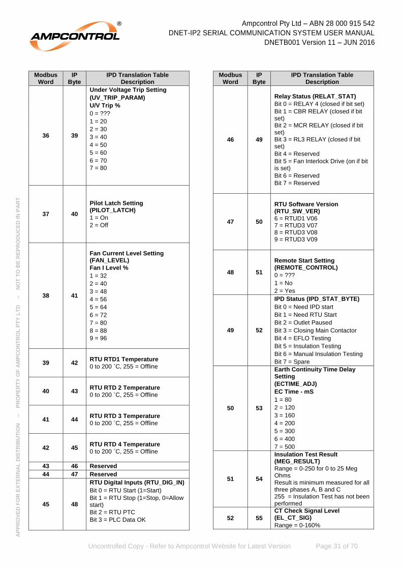
36 39
Under Voltage Trip Setting
(UV_TRIP_PARAM)
U/V Trip %
0 = ???
1 = 20
2 = 30
3 = 40
4 = 50
5 = 60
6 = 70
7 = 80
37 40
Pilot Latch Setting (PILOT_LATCH)
1 = On
2 = Off
38 41
Fan Current Level Setting (FAN_LEVEL)
Fan I Level %
1 = 32
2 = 40
3 = 48
4 = 56
5 = 64
6 = 72
7 = 80
8 = 88
9 = 96
39 42
RTU RTD1 Temperature
0 to 200 ˚C, 255 = Offline
40 43
RTU RTD 2 Temperature
0 to 200 ˚C, 255 = Offline
41 44
RTU RTD 3 Temperature
0 to 200 ˚C, 255 = Offline
42 45
RTU RTD 4 Temperature
0 to 200 ˚C, 255 = Offline
43 46 Reserved
44 47 Reserved
45 48
RTU Digital Inputs (RTU_DIG_IN)
Bit 0 = RTU Start (1=Start)
Bit 1 = RTU Stop (1=Stop, 0=Allow start)
Bit 2 = RTU PTC
Bit 3 = PLC Data OK
Modbus Word
IP Byte
IPD Translation Table Description
46 49
Relay Status (RELAT_STAT)
Bit 0 = RELAY 4 (closed if bit set)
Bit 1 = CBR RELAY (closed if bit set) Bit 2 = MCR RELAY (closed if bit set) Bit 3 = RL3 RELAY (closed if bit set)
Bit 4 = Reserved
Bit 5 = Fan Interlock Drive (on if bit is set)
Bit 6 = Reserved
Bit 7 = Reserved
47 50
RTU Software Version (RTU_SW_VER)
6 = RTUD1 V06 7 = RTUD3 V07 8 = RTUD3 V08 9 = RTUD3 V09
48 51
Remote Start Setting (REMOTE_CONTROL)
0 = ???
1 = No
2 = Yes
49 52
IPD Status (IPD_STAT_BYTE)
Bit 0 = Need IPD start
Bit 1 = Need RTU Start
Bit 2 = Outlet Paused
Bit 3 = Closing Main Contactor
Bit 4 = EFLO Testing
Bit 5 = Insulation Testing
Bit 6 = Manual Insulation Testing
Bit 7 = Spare
50 53
Earth Continuity Time Delay Setting
(ECTIME_ADJ)
EC Time - mS
1 = 80
2 = 120
3 = 160
4 = 200
5 = 300
6 = 400
7 = 500
51 54
Insulation Test Result (MEG_RESULT)
Range = 0-250 for 0 to 25 Meg Ohms Result is minimum measured for all three phases A, B and C 255 = Insulation Test has not been performed
52 55
CT Check Signal Level (EL_CT_SIG)
Range = 0-160%

Ampcontrol Pty Ltd – ABN 28 000 915 542
DNET-IP2 SERIAL COMMUNICATION SYSTEM USER MANUAL
DNETB001 Version 11 – JUN 2016
Uncontrolled Copy - Refer to Ampcontrol Website for Latest Version Page 32 of 70
AP
PR
OV
ED
FO
R E
XT
ER
NA
L D
IST
RIB
UT
ION
– P
RO
PE
RT
Y O
F A
MP
CO
NT
RO
L P
TY
LT
D
–
NO
T T
O B
E R
EP
RO
DU
CE
D IN
PA
RT
Modbus Word
IP Byte
IPD Translation Table Description
53 56
IPD Alarm Status (IPD_ALARM_BYTE)
Bit 0 = Tripped-No Volts
Bit 1 = MC Close Fail
Bit 2 = External MC Open
Bit 3 = Insulation Alarm
Bit 4 = CT Trip
Bit 5 = Spare
Bit 6 = Spare
Bit 7 = Reserved: Do not use
54 57 Reserved
55 58 Reserved
56 59 Reserved
57 60 Reserved
58 61 Reserved
59 62
Transient Inrush Parameter (TRANS_PARAM)
0 = ??? 1 = Disabled 2 = 40ms 3 = 60ms 4 = 80ms 5 = 100ms 6 = 120ms
60 63 Checksum (Low order byte of sum of all IP bytes

Ampcontrol Pty Ltd – ABN 28 000 915 542
DNET-IP2 SERIAL COMMUNICATION SYSTEM USER MANUAL
DNETB001 Version 11 – JUN 2016
Uncontrolled Copy - Refer to Ampcontrol Website for Latest Version Page 33 of 70
AP
PR
OV
ED
FO
R E
XT
ER
NA
L D
IST
RIB
UT
ION
– P
RO
PE
RT
Y O
F A
MP
CO
NT
RO
L P
TY
LT
D
–
NO
T T
O B
E R
EP
RO
DU
CE
D IN
PA
RT
7.3 IPC Translation TableModbus
Word IP
Byte IPC Translation Table
Description
1 0 IPSI Address
Bits 0..3 = IPSI Address (Range 1-15)
N/A 1
Digital Inputs (DIG_INPUTS)
Bit 0 = Main Contactor fail Flag Bit 1 = Reserved Bit 2 = IPC Start Input Bit 3 = Fan Interlock Read: 0 = Ok to run Bit 4 = IPC Lock Digital Input: 0 = Input closed Bit 5 = IPC Reset Digital Input: 0 = Input closed Bit 6 = MCI Digital Input: 0 = Input closed
N/A 2
Opto Status (OPTOSTAT)
Bit 0 = Earth Leakage Trip
Bit 1 = Earth Continuity Trip
Bit 2 = E/F Lockout Trip
Bit 3 = Over Current Trip
Bit 4 = Short Circuit Trip
Bit 5 = Main Conttactor Fail
Bit 6 = Insulation Fail
Bit 7 = Running ----Amps
2 N/A
Opto Status/Digital Inputs (OPTOSTAT+DIG_INPUTS)
Bit 0 = Earth leakage Trip Bit 1 = Earth Continuity Trip Bit 2 = Earth Fault Lockout Bit 3 = Overload Bit 4 = Short circuit Bit 5 = MCF Bit Bit 6 = Insulation Fail Bit 7 = Outlet Run Bit 8 = IP2 to IPSI Comms OK Bit 9 = IPSI to IPC Comms OK Bit 10 = Fan Interlock Read Bit 11 = IPC Stop digital Input Bit 12 = IPC Reset Digital Input Bit 13 = IPC Lock Digital Input Bit 14 = IPC MCI Digital Input Bit 15 = IPC Start Digital Input
3 3
Earth Leakage Current (EL_CUR)
Range 0-100%
4 4
Pilot Series Resistance (PILOT_FWD)
Range 0-200%
5 5
Pilot Leakage Resistance (PILOT_REV)
Range 0-120%
6 6
Cable Fault Lockout Leakage (CFLR_LEAK)
Range 0-100%
7 7,8
A Phase Current (CUR_A_BCD_HIGH)
Range 0-999%
8 9,10
B Phase Current (CUR_B_BCD_HIGH)
Range 0-999%
Modbus Word
IP Byte
IPC Translation Table Description
9 11,12
C Phase Current (CUR_C_BCD_HIGH)
Range 0-999%
10 13
Over Current Trip (OC TRIP_HIGH)
Range 0-120%
11 14
Current Balance (CURRENT_BAL)
Range 0-100%
12 15
A Phase Volts (VOLTS_A)
Range 0-120%
13 16
B Phase Volts (VOLTS_B)
Range 0-120%
14 17
C Phase Volts (VOLTS_C)
Range 0-120%
15 18
Trip Status (TRIP_STAT2)
Bit 0 = IPC Memory Error
Bit 1 = RTU Memory Error
Bit 2 = Trip - RTU Offline
Bit 3 = Stopped - RTU PTC
Bit 4 = Stopped - RTU
Bit 5 = I Balance Trip
Bit 6 = Locked Out - Fan Bit 7 = Stopped IPC
16 19 Reserved
17 20
IPC Software Version (IPC_SW_VER)
1 = IPB3 V0.1 1994
2 = IPB3 V0.2 1995 3 =IPB4 V0.2 1994, IPB 4 V0.1 1995 5 = IPB5 V 02 1997, IPB4 X 02 1996
6 = IPB5 V 03 1997
7 = IPB5 V 04 1997
8 = IPB6 V 01 1998
9 = IPB6 V 01a 1998
10-19 = Reserved
20 = IPC1 V 01 2001
21 = IPC1 V 02 2002 22 = IPC1 V 03 2004 23 = IPC1 V 04 2006 24 = IPC1 V 05 2009
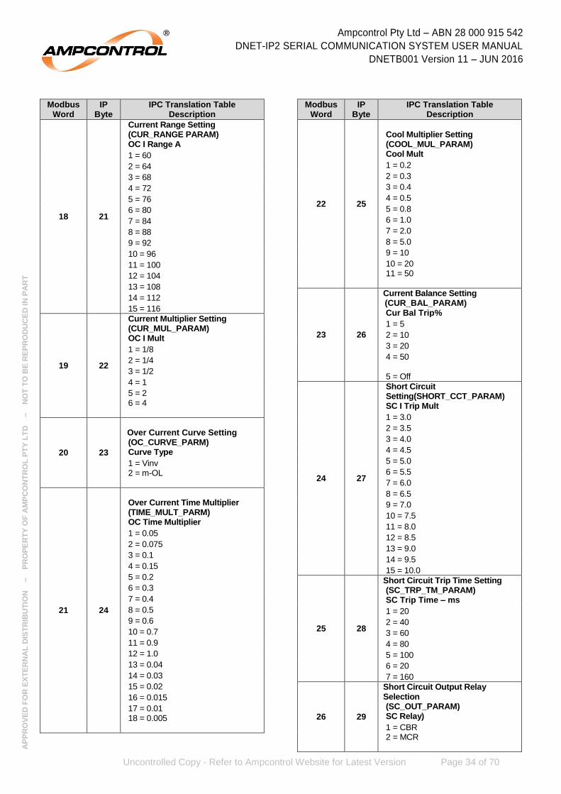
Ampcontrol Pty Ltd – ABN 28 000 915 542
DNET-IP2 SERIAL COMMUNICATION SYSTEM USER MANUAL
DNETB001 Version 11 – JUN 2016
Uncontrolled Copy - Refer to Ampcontrol Website for Latest Version Page 34 of 70
AP
PR
OV
ED
FO
R E
XT
ER
NA
L D
IST
RIB
UT
ION
– P
RO
PE
RT
Y O
F A
MP
CO
NT
RO
L P
TY
LT
D
–
NO
T T
O B
E R
EP
RO
DU
CE
D IN
PA
RT
Modbus Word
IP Byte
IPC Translation Table Description
18 21
Current Range Setting (CUR_RANGE PARAM) OC I Range A
1 = 60
2 = 64
3 = 68
4 = 72
5 = 76
6 = 80
7 = 84
8 = 88
9 = 92
10 = 96
11 = 100
12 = 104
13 = 108
14 = 112
15 = 116
19 22
Current Multiplier Setting (CUR_MUL_PARAM) OC I Mult
1 = 1/8
2 = 1/4
3 = 1/2
4 = 1
5 = 2 6 = 4
20 23
Over Current Curve Setting (OC_CURVE_PARM) Curve Type
1 = Vinv 2 = m-OL
21 24
Over Current Time Multiplier (TIME_MULT_PARM) OC Time Multiplier
1 = 0.05
2 = 0.075
3 = 0.1
4 = 0.15
5 = 0.2
6 = 0.3
7 = 0.4
8 = 0.5
9 = 0.6
10 = 0.7
11 = 0.9
12 = 1.0
13 = 0.04
14 = 0.03
15 = 0.02
16 = 0.015
17 = 0.01 18 = 0.005
Modbus Word
IP Byte
IPC Translation Table Description
22 25
Cool Multiplier Setting (COOL_MUL_PARAM) Cool Mult
1 = 0.2
2 = 0.3
3 = 0.4
4 = 0.5
5 = 0.8
6 = 1.0
7 = 2.0
8 = 5.0
9 = 10
10 = 20 11 = 50
23 26
Current Balance Setting (CUR_BAL_PARAM) Cur Bal Trip%
1 = 5
2 = 10
3 = 20
4 = 50
5 = Off
24 27
Short Circuit Setting(SHORT_CCT_PARAM) SC I Trip Mult
1 = 3.0
2 = 3.5
3 = 4.0
4 = 4.5
5 = 5.0
6 = 5.5
7 = 6.0
8 = 6.5
9 = 7.0
10 = 7.5
11 = 8.0
12 = 8.5
13 = 9.0
14 = 9.5
15 = 10.0
25 28
Short Circuit Trip Time Setting (SC_TRP_TM_PARAM) SC Trip Time – ms
1 = 20
2 = 40
3 = 60
4 = 80
5 = 100
6 = 20
7 = 160
26 29
Short Circuit Output Relay Selection (SC_OUT_PARAM) SC Relay)
1 = CBR 2 = MCR
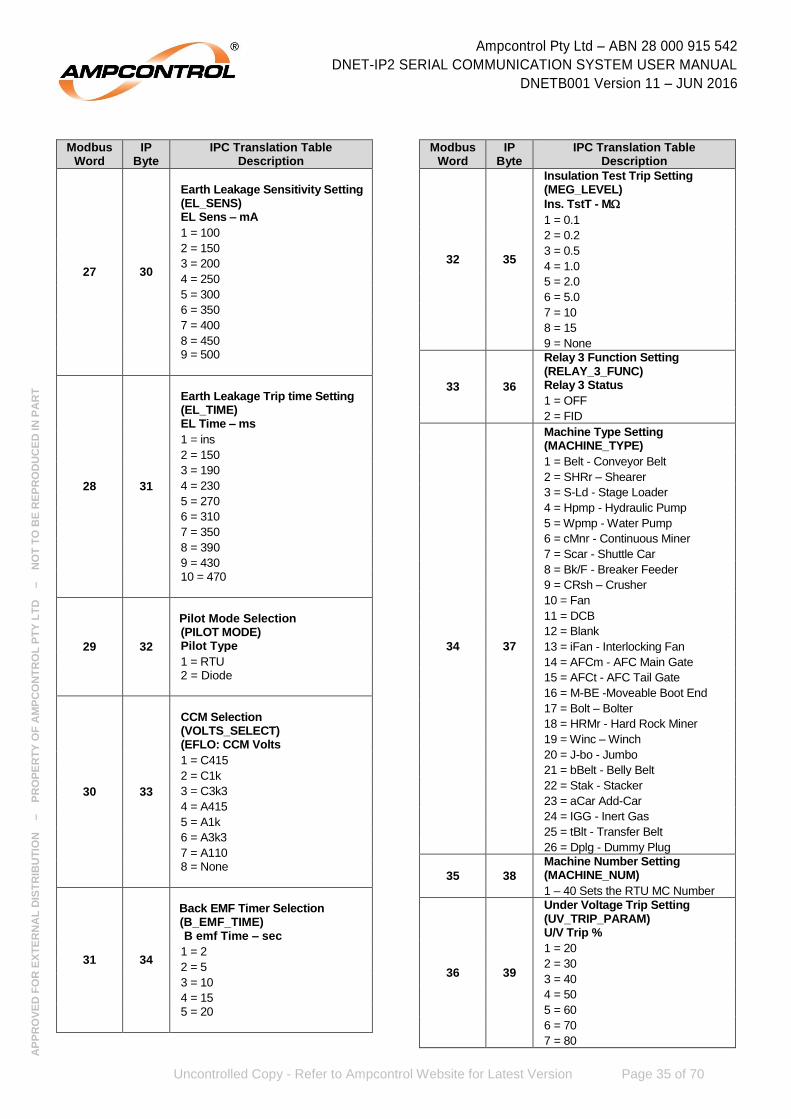
Ampcontrol Pty Ltd – ABN 28 000 915 542
DNET-IP2 SERIAL COMMUNICATION SYSTEM USER MANUAL
DNETB001 Version 11 – JUN 2016
Uncontrolled Copy - Refer to Ampcontrol Website for Latest Version Page 35 of 70
AP
PR
OV
ED
FO
R E
XT
ER
NA
L D
IST
RIB
UT
ION
– P
RO
PE
RT
Y O
F A
MP
CO
NT
RO
L P
TY
LT
D
–
NO
T T
O B
E R
EP
RO
DU
CE
D IN
PA
RT
Modbus Word
IP Byte
IPC Translation Table Description
27 30
Earth Leakage Sensitivity Setting (EL_SENS) EL Sens – mA
1 = 100
2 = 150
3 = 200
4 = 250
5 = 300
6 = 350
7 = 400
8 = 450 9 = 500
28 31
Earth Leakage Trip time Setting (EL_TIME) EL Time – ms
1 = ins
2 = 150
3 = 190
4 = 230
5 = 270
6 = 310
7 = 350
8 = 390
9 = 430 10 = 470
29 32
Pilot Mode Selection (PILOT MODE) Pilot Type
1 = RTU 2 = Diode
30 33
CCM Selection (VOLTS_SELECT) (EFLO: CCM Volts
1 = C415
2 = C1k
3 = C3k3
4 = A415
5 = A1k
6 = A3k3
7 = A110 8 = None
31 34
Back EMF Timer Selection (B_EMF_TIME) B emf Time – sec
1 = 2
2 = 5
3 = 10
4 = 15 5 = 20
Modbus Word
IP Byte
IPC Translation Table Description
32 35
Insulation Test Trip Setting (MEG_LEVEL)
Ins. TstT - M
1 = 0.1
2 = 0.2
3 = 0.5
4 = 1.0
5 = 2.0
6 = 5.0
7 = 10
8 = 15
9 = None
33 36
Relay 3 Function Setting (RELAY_3_FUNC) Relay 3 Status
1 = OFF
2 = FID
Machine Type Setting (MACHINE_TYPE)
34 37
1 = Belt - Conveyor Belt
2 = SHRr – Shearer
3 = S-Ld - Stage Loader
4 = Hpmp - Hydraulic Pump
5 = Wpmp - Water Pump
6 = cMnr - Continuous Miner
7 = Scar - Shuttle Car
8 = Bk/F - Breaker Feeder
9 = CRsh – Crusher
10 = Fan
11 = DCB
12 = Blank
13 = iFan - Interlocking Fan
14 = AFCm - AFC Main Gate
15 = AFCt - AFC Tail Gate
16 = M-BE -Moveable Boot End
17 = Bolt – Bolter
18 = HRMr - Hard Rock Miner
19 = Winc – Winch
20 = J-bo - Jumbo
21 = bBelt - Belly Belt
22 = Stak - Stacker
23 = aCar Add-Car
24 = IGG - Inert Gas
25 = tBlt - Transfer Belt
26 = Dplg - Dummy Plug
35 38
Machine Number Setting (MACHINE_NUM)
1 – 40 Sets the RTU MC Number
36 39
Under Voltage Trip Setting (UV_TRIP_PARAM) U/V Trip %
1 = 20
2 = 30
3 = 40
4 = 50
5 = 60
6 = 70
7 = 80

Ampcontrol Pty Ltd – ABN 28 000 915 542
DNET-IP2 SERIAL COMMUNICATION SYSTEM USER MANUAL
DNETB001 Version 11 – JUN 2016
Uncontrolled Copy - Refer to Ampcontrol Website for Latest Version Page 36 of 70
AP
PR
OV
ED
FO
R E
XT
ER
NA
L D
IST
RIB
UT
ION
– P
RO
PE
RT
Y O
F A
MP
CO
NT
RO
L P
TY
LT
D
–
NO
T T
O B
E R
EP
RO
DU
CE
D IN
PA
RT
Modbus Word
IP Byte
IPC Translation Table Description
37 40
Pilot Latch Setting (PILOT_LATCH)
1 = On
2 = Off
38 41
Fan Current Level Setting (FAN_LEVEL) Fan I Level %
1 = 32
2 = 40
3 = 48
4 = 56
5 = 64
6 = 72
7 = 80
8 = 88
9 = 96
39 42 RTU RTD1 Temperature
0 to 200 C, 255 = Offline
40 43 RTU RTD 2 Temperature
0 to 200 C, 255 = Offline
41 44 RTU RTD 3 Temperature
0 to 200 C, 255 = Offline
42 45 RTU RTD 4 Temperature
0 to 200 C, 255 = Offline
43 46 RTU CIU Data Byte 0
Range = 0-255, 255 = Offline
44 47 RTU CIU Data Byte 1
Range = 0-255, 255 = Offline
45 48
RTU Digital Inputs (RTU_DIG_IN)
Bit 0 = RTU Start (1=Start) Bit 1 = RTU Stop (1=Stop, 0=Allow start)
Bit 2 = RTU PTC
Bit 3 = PLC Data OK
46 49
Relay Status (RELAT_STAT)
Bit 0 = RELAY 4 (closed if bit set) Bit 1 = CBR RELAY (closed if bit set) Bit 2 = MCR RELAY (closed if bit set) Bit 3 = RL3 RELAY (closed if bit set)
Bit 4 = Reserved Bit 5 = Fan Interlock Drive (on if bit is set)
Bit 6 = Reserved
Bit 7 = Reserved
47 50
RTU Software Version (RTU_SW_VER)
1 = RTU4V4.1
2 = Reserved
3 = RTU4V4.2, RTU5V01
4 = RTU5V02
48 51
Remote Start Setting (REMOTE_CONTROL)
1 = No
2 = Yes
Modbus Word
IP Byte
IPC Translation Table Description
49 52
IPC Status (IPC_STAT_BYTE)
Bit 0 = Need IPC start
Bit 1 = Need RTU Start
Bit 2 = Outlet Paused
Bit 3 = Closing Main Contactor
Bit 4 = EFLO Testing
Bit 5 = Insulation Testing
Bit 6 = Manual Insulation Testing
Bit 7 = Spare
50 53
Earth Continuity Time Delay Setting
(ECTIME_ADJ) EC Time - ms
1 = 80
2 = 120
3 = 160
4 = 200
5 = 300
6 = 400 7 = 500
51 54
Insulation Test Result (MEG_RESULT)
Range = 0-250 for 0 to 25 Meg Ohms Result is minimum measured for all three phases A, B and C 255 = Insulation Test has not been performed
52 55 Reserved
53 56
IPC Alarm Status (IPC_ALARM_BYTE)
Bit 0 = Tripped-No Volts
Bit 1 = MC Close Fail
Bit 2 = External MC Open
Bit 3 = Insulation Alarm
Bit 4 = Spare
Bit 5 = Spare
Bit 6 = Spare
Bit 7 = Reserved: Do not use
54 57 RTU CIU Data Byte 2
Range = 0-255, 255 = Offline
55 58 RTU CIU Data Byte 3
Range = 0-255, 255 = Offline
56 59 RTU CIU Data Byte 4
Range = 0-255, 255 = Offline
57 60 RTU CIU Data Byte 5
Range = 0-255, 255 = Offline
58 61 RTU CIU Data Byte 6
Range = 0-255, 255 = Offline
59 62 RTU CIU Data Byte 7
Range = 0-255, 255 = Offline
60 63 Checksum (Low order byte of sum of all IP bytes

Ampcontrol Pty Ltd – ABN 28 000 915 542
DNET-IP2 SERIAL COMMUNICATION SYSTEM USER MANUAL
DNETB001 Version 11 – JUN 2016
Uncontrolled Copy - Refer to Ampcontrol Website for Latest Version Page 37 of 70
AP
PR
OV
ED
FO
R E
XT
ER
NA
L D
IST
RIB
UT
ION
– P
RO
PE
RT
Y O
F A
MP
CO
NT
RO
L P
TY
LT
D
–
NO
T T
O B
E R
EP
RO
DU
CE
D IN
PA
RT
7.4 HPB 22kV Translation Table (Standard and Low EL Version)Modbus
Word IP
Byte HPB 22kV Translation Table
Description
N/A 0 IPSI Address
Bits 0..3 = IPSI Address (Range 1-15)
1 N/A
IPSI Address
Bits 0..3 = IPSI Address (Range 1-15) Bit 8 = IPSI Online Bit 9 = HPB Online
N/A 1
Digital Inputs (DIG_INPUTS)
Bit 0 = 1 Indicates HPB Relay Bit 1 = Communications to HPB: 0 = Error
Bit 2 = Undefined
Bit 3 = HPB Stop Digital Input: 1 = Input closed Bit 4 = HPB Reset Digital Input: 1 = Input closed Bit 5 = HPB Lock Digital Input: 1 = Input closed Bit 6 = MCI Digital Input: 1 = Input closed Bit 7 = HPB Start Digital Input: 1 = Input closed
N/A 2
Opto Status (OPTOSTAT)
Bit 0 = Earth Leakage Trip
Bit 1 = Earth Continuity Trip
Bit 2 = E/F Lockout Trip
Bit 3 = Over Current Trip
Bit 4 = Short Circuit Trip
Bit 5 = Main Contactor Fail
Bit 6 = Unused
Bit 7 = Running
2 N/A
Opto Status/Digital Inputs
(OPTOSTAT+DIG_INPUTS)
Bit 0 = Earth Leakage Trip
Bit 1 = Earth Continuity Trip
Bit 2 = E/F Lockout Trip
Bit 3 = Over Current Trip
Bit 4 = Short Circuit Trip
Bit 5 = Main Contactor Fail
Bit 6 = Unused
Bit 7 = Running
Bit 8 = 1 Indicates HPB Relay
Bit 9 = Communications to HPB: 0 = Error
Bit 10 = Undefined
Bit 11 = HPB Stop Digital Input: 1 = Input closed Bit 12 = HPB Reset Digital Input: 1 = Input closed Bit 13 = HPB Lock Digital Input: 1 = Input closed Bit 14 = MCI Digital Input: 1 = Input closed Bit 15 = HPB Start Digital Input: 1 = Input closed
3 3 Earth Leakage Current (EL_CUR)
Range 0-110%
Modbus Word
IP Byte
HPB 22kV Translation Table Description
4 4
Pilot Series Resistance (PILOT_FWD)
Range 0-150Ω
5 5 Reserved
6 6 Reserved
7 7,8
A Phase Current (CUR_A_BCD_HIGH)
Range 0-999%
8 9,10
B Phase Current (CUR_B_BCD_HIGH)
Range 0-999%
9 11,12
C Phase Current (CUR_C_BCD_HIGH)
Range 0-999%
10 13
Over Current Trip (OC TRIP_HIGH)
Range 0-120%
11 14
Current Balance (CURRENT_BAL)
Range 0-100%
12 15 A Phase Volts (VOLTS_A)
Range 0-140%
13 16 B Phase Volts (VOLTS_B)
Range 0-140%
14 17 C Phase Volts (VOLTS_C)
Range 0-140%
15 18
Trip Status (TRIP_STAT)
Bit 0 = HPB Memory: 1 = Error
Bit 1 = RTU Memory: 1 = Error
16 19 Reserved
17 20 Reserved
18 21
Current Range Setting
(CUR_RANGE PARAM)
OC I Range A
0 = ???
1 = 60
2 = 64
3 = 68
4 = 72
5 = 76
6 = 80
7 = 84
8 = 88
9 = 92
10 = 96
11 = 100
12 = 104
13 = 108
14 = 112
15 = 116

Ampcontrol Pty Ltd – ABN 28 000 915 542
DNET-IP2 SERIAL COMMUNICATION SYSTEM USER MANUAL
DNETB001 Version 11 – JUN 2016
Uncontrolled Copy - Refer to Ampcontrol Website for Latest Version Page 38 of 70
AP
PR
OV
ED
FO
R E
XT
ER
NA
L D
IST
RIB
UT
ION
– P
RO
PE
RT
Y O
F A
MP
CO
NT
RO
L P
TY
LT
D
–
NO
T T
O B
E R
EP
RO
DU
CE
D IN
PA
RT
Modbus Word
IP Byte
HPB 22kV Translation Table Description
19 22
Current Multiplier Setting
(CUR_MUL_PARAM)
OC I Mult
0 = ???
1 = 1/4
2 = 1/2
3 = 1
4 = 2
5 = 4
6 = 8
20 23
Over Current Curve Setting
(OC_CURVE_PARM)
Curve Type
0 = ???
1 = Vinv
2 = xInv
21 24
Over Current Time Multiplier
(TIME_MULT_PARM)
0 = ???
1 = 0.05
2 = 0.075
3 = 0.1
4 = 0.15
5 = 0.2
6 = 0.3
7 = 0.4
8 = 0.5
9 = 0.6
10 = 0.7
11 = 0.8
12 = 0.9
13 = 1.0
22 25 Reserved
23 26
Current Balance Setting
(CUR_BAL_PARAM)
Cur Bal Trip%
0 = ???
1 = 5
2 = 10
3 = 20
4 = 50
5 = Off
Modbus Word
IP Byte
HPB 22kV Translation Table Description
24 27
Short Circuit Setting (SHORT_CCT_PARAM)
SC I Trip Mult
0 = ???
1 = 3.0
2 = 3.5
3 = 4.0
4 = 4.5
5 = 5.0
6 = 5.5
7 = 6.0
8 = 6.5
9 = 7.0
10 = 7.5
11 = 8.0
12 = 8.5
13 = 9.0
14 = 9.5
15 = 10
25 28
Short Circuit Trip Time Setting
(SC_TRP_TM_PARAM)
SC Trip Time – ms
0 = ???
1 = 40
2 = 60
3 = 80
4 = 100
5 = 120
6 = 160
Short Circuit Output Relay Selection
26 29
(SC_OUT_PARAM)
SC Relay)
0 = ???
1 = CBR
2 = MCR

Ampcontrol Pty Ltd – ABN 28 000 915 542
DNET-IP2 SERIAL COMMUNICATION SYSTEM USER MANUAL
DNETB001 Version 11 – JUN 2016
Uncontrolled Copy - Refer to Ampcontrol Website for Latest Version Page 39 of 70
AP
PR
OV
ED
FO
R E
XT
ER
NA
L D
IST
RIB
UT
ION
– P
RO
PE
RT
Y O
F A
MP
CO
NT
RO
L P
TY
LT
D
–
NO
T T
O B
E R
EP
RO
DU
CE
D IN
PA
RT
Modbus Word
IP Byte
HPB 22kV Translation Table Description
27 30
Earth Leakage Sensitivity Setting
(EL_SENS)
EL Sens – mA
0 = ???
1 < 500
2 < 7500
3 < 1000
4 < 1250
5 < 1500
6 < 1750
7 < 2000
8 < 2250
9 < 2500 Earth Leakage Sensitivity Setting – LOW EL VERSION (EL_SENS) EL Sens – mA
0 = ??? 1 < 200 2 < 300 3 < 400 4 < 500 5 < 600 6 < 700 7 < 800 8 < 900 9 < 1000
28 31
Earth Leakage Trip time Setting
(EL_TIME)
EL Time – ms
0 = ???
1 = ins
2 = 150
3 = 190
4 = 230
5 = 270
6 = 310
7 = 350
8 = 390
9 = 430
10 = 470
29 32
Pilot Mode Selection
(PILOT MODE)
Pilot Type
0 = ???
1 = HTU
2 = Res
30 33
EFLO Select
(EFLO_SELECT)
EF - M Ohm
0 = ???
1 = 15
2 = 20
3 = 30
4 = 50
5 = 100
6 = Off
Modbus Word
IP Byte
HPB 22kV Translation Table Description
31 34
Back EMF Timer Selection
(B_EMF_TIME)
B emf Time – sec
0 = ???
1 = 2
2 = 5
3 = 10
4 = 15
5 = 20
6 = 25
7 = 30
8 = 35
9 = 40
32 35 Reserved
33 36
Earth Leakage Level
0 = Hardware Fault
1 = Insulation reading < 10MΩ
2 - 9 = Invalid
10 – 120 =
Insulation reading in MΩ
121 – 253 =
Invalid
254 = Insulation reading >120 MΩ
255 = Invalid
34 37
Machine Type Setting
(MACHINE_TYPE)
0 = ???
1 = DrgL - Dragline
2 = Shvl - Shovel
3 = Dril - Drill
4 = pSTx – Portable Starting Transformer
5 = Wpmp - Water Pump
6 = Blank
35 38
Machine Number Setting (MACHINE_NUM)
0 = ???
1 – 40 Sets the RTU MC Number
36 39
Under Voltage Trip Setting
(UV_TRIP_PARAM)
U/V Trip %
1 = None
2 = 30
3 = 40
4 = 50
5 = 60
6 = 70
7 = 80
37 40
Pilot Latch Setting (PILOT_LATCH)
0 = ???
1 = On
2 = Off

Ampcontrol Pty Ltd – ABN 28 000 915 542
DNET-IP2 SERIAL COMMUNICATION SYSTEM USER MANUAL
DNETB001 Version 11 – JUN 2016
Uncontrolled Copy - Refer to Ampcontrol Website for Latest Version Page 40 of 70
AP
PR
OV
ED
FO
R E
XT
ER
NA
L D
IST
RIB
UT
ION
– P
RO
PE
RT
Y O
F A
MP
CO
NT
RO
L P
TY
LT
D
–
NO
T T
O B
E R
EP
RO
DU
CE
D IN
PA
RT
Modbus Word
IP Byte
HPB 22kV Translation Table Description
38 41
Earth Fault Lockout Time Setting (EF_LOCKOUT_TIME)
EF Lockout Time Seconds
0 = ???
1 = 10
2 = 15
3 = 20
4 = 25
39 42 Reserved
40 43 Reserved
41 44 Reserved
42 45 Reserved
43 46 Reserved
44 47 Reserved
45 48
RTU Digital Inputs (RTU_DIG_IN)
Bit 0 = HTU Run
Bit 1 = HTU Online
46 49
Relay Status (RELAT_STAT)
Bit 0 = RELAY 4 (closed if bit set)
Bit 1 = CBR RELAY (closed if bit set) Bit 2 = MCR RELAY (closed if bit set) Bit 3 = RL3 RELAY (closed if bit set)
Bit 4 = Reserved
Bit 5 = Undefined
Bit 6 = Heart Beat LED Drive
Bit 7 = MCF Trip Flag
47 50 Reserved
48 51 Reserved
49 52 Reserved
50 53
EC Time
(ECTIME_ADJ)
0 = ???
1 = 300ms
2 = 400ms
3 = 500ms
4 = 600ms
5 = 800ms
6 = 1s
7 = 1.2s
8 = 1.5s
9 = 2s
51 54 Reserved
52 55 Reserved
53 56 Reserved
54 57 Reserved
55 58 Reserved
56 59 Reserved
57 60 Reserved
58 61 Reserved
59 62 Reserved
60 63 Checksum (Low order byte of sum of all IP bytes
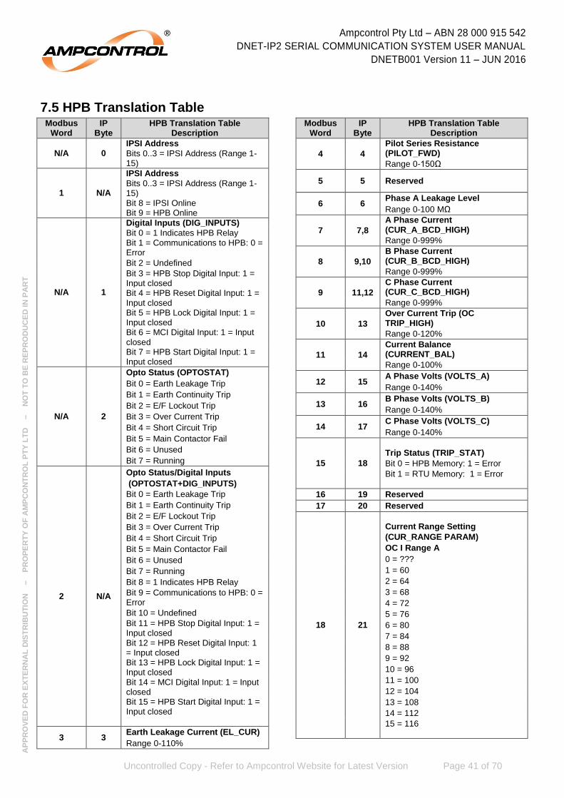
Ampcontrol Pty Ltd – ABN 28 000 915 542
DNET-IP2 SERIAL COMMUNICATION SYSTEM USER MANUAL
DNETB001 Version 11 – JUN 2016
Uncontrolled Copy - Refer to Ampcontrol Website for Latest Version Page 41 of 70
AP
PR
OV
ED
FO
R E
XT
ER
NA
L D
IST
RIB
UT
ION
– P
RO
PE
RT
Y O
F A
MP
CO
NT
RO
L P
TY
LT
D
–
NO
T T
O B
E R
EP
RO
DU
CE
D IN
PA
RT
7.5 HPB Translation TableModbus
Word IP
Byte HPB Translation Table
Description
N/A 0 IPSI Address
Bits 0..3 = IPSI Address (Range 1-15)
1 N/A
IPSI Address
Bits 0..3 = IPSI Address (Range 1-15) Bit 8 = IPSI Online Bit 9 = HPB Online
N/A 1
Digital Inputs (DIG_INPUTS)
Bit 0 = 1 Indicates HPB Relay Bit 1 = Communications to HPB: 0 = Error
Bit 2 = Undefined
Bit 3 = HPB Stop Digital Input: 1 = Input closed Bit 4 = HPB Reset Digital Input: 1 = Input closed Bit 5 = HPB Lock Digital Input: 1 = Input closed Bit 6 = MCI Digital Input: 1 = Input closed Bit 7 = HPB Start Digital Input: 1 = Input closed
N/A 2
Opto Status (OPTOSTAT)
Bit 0 = Earth Leakage Trip
Bit 1 = Earth Continuity Trip
Bit 2 = E/F Lockout Trip
Bit 3 = Over Current Trip
Bit 4 = Short Circuit Trip
Bit 5 = Main Contactor Fail
Bit 6 = Unused
Bit 7 = Running
2 N/A
Opto Status/Digital Inputs
(OPTOSTAT+DIG_INPUTS)
Bit 0 = Earth Leakage Trip
Bit 1 = Earth Continuity Trip
Bit 2 = E/F Lockout Trip
Bit 3 = Over Current Trip
Bit 4 = Short Circuit Trip
Bit 5 = Main Contactor Fail
Bit 6 = Unused
Bit 7 = Running
Bit 8 = 1 Indicates HPB Relay
Bit 9 = Communications to HPB: 0 = Error
Bit 10 = Undefined
Bit 11 = HPB Stop Digital Input: 1 = Input closed Bit 12 = HPB Reset Digital Input: 1 = Input closed Bit 13 = HPB Lock Digital Input: 1 = Input closed Bit 14 = MCI Digital Input: 1 = Input closed Bit 15 = HPB Start Digital Input: 1 = Input closed
3 3 Earth Leakage Current (EL_CUR)
Range 0-110%
Modbus Word
IP Byte
HPB Translation Table Description
4 4
Pilot Series Resistance (PILOT_FWD)
Range 0-150Ω
5 5 Reserved
6 6 Phase A Leakage Level
Range 0-100 MΩ
7 7,8
A Phase Current (CUR_A_BCD_HIGH)
Range 0-999%
8 9,10
B Phase Current (CUR_B_BCD_HIGH)
Range 0-999%
9 11,12
C Phase Current (CUR_C_BCD_HIGH)
Range 0-999%
10 13
Over Current Trip (OC TRIP_HIGH)
Range 0-120%
11 14
Current Balance (CURRENT_BAL)
Range 0-100%
12 15 A Phase Volts (VOLTS_A)
Range 0-140%
13 16 B Phase Volts (VOLTS_B)
Range 0-140%
14 17 C Phase Volts (VOLTS_C)
Range 0-140%
15 18
Trip Status (TRIP_STAT)
Bit 0 = HPB Memory: 1 = Error
Bit 1 = RTU Memory: 1 = Error
16 19 Reserved
17 20 Reserved
18 21
Current Range Setting
(CUR_RANGE PARAM)
OC I Range A
0 = ???
1 = 60
2 = 64
3 = 68
4 = 72
5 = 76
6 = 80
7 = 84
8 = 88
9 = 92
10 = 96
11 = 100
12 = 104
13 = 108
14 = 112
15 = 116

Ampcontrol Pty Ltd – ABN 28 000 915 542
DNET-IP2 SERIAL COMMUNICATION SYSTEM USER MANUAL
DNETB001 Version 11 – JUN 2016
Uncontrolled Copy - Refer to Ampcontrol Website for Latest Version Page 42 of 70
AP
PR
OV
ED
FO
R E
XT
ER
NA
L D
IST
RIB
UT
ION
– P
RO
PE
RT
Y O
F A
MP
CO
NT
RO
L P
TY
LT
D
–
NO
T T
O B
E R
EP
RO
DU
CE
D IN
PA
RT
Modbus Word
IP Byte
HPB Translation Table Description
19 22
Current Multiplier Setting
(CUR_MUL_PARAM)
OC I Mult
0 = ???
1 = 1/8
2 = 1/4
3 = 1/2
4 = 1
5 = 2
6 = 4
20 23
Over Current Curve Setting
(OC_CURVE_PARM)
Curve Type
0 = ???
1 = Vinv
2 = xInv
21 24
Over Current Time Multiplier
(TIME_MULT_PARM)
0 = ???
1 = 0.05
2 = 0.075
3 = 0.1
4 = 0.15
5 = 0.2
6 = 0.3
7 = 0.4
8 = 0.5
9 = 0.6
10 = 0.7
11 = 0.8
12 = 0.9
13 = 1.0
22 25 Reserved
23 26
Current Balance Setting
(CUR_BAL_PARAM)
Cur Bal Trip%
0 = ???
1 = 5
2 = 10
3 = 20
4 = 50
5 = Off
Modbus Word
IP Byte
HPB Translation Table Description
24 27
Short Circuit Setting (SHORT_CCT_PARAM)
SC I Trip Mult
0 = ???
1 = 3.0
2 = 3.5
3 = 4.0
4 = 4.5
5 = 5.0
6 = 5.5
7 = 6.0
8 = 6.5
9 = 7.0
10 = 7.5
11 = 8.0
12 = 8.5
13 = 9.0
14 = 9.5
15 = 10
25 28
Short Circuit Trip Time Setting
(SC_TRP_TM_PARAM)
SC Trip Time – ms
0 = ???
1 = 40
2 = 60
3 = 80
4 = 100
5 = 120
6 = 160
26 29
Short Circuit Output Relay Selection
(SC_OUT_PARAM)
SC Relay)
0 = ???
1 = CBR
2 = MCR
27 30
Earth Leakage Sensitivity Setting
(EL_SENS)
EL Sens – mA
0 = ???
1 < 200
2 < 300
3 < 400
4 < 500
5 < 600
6 < 700
7 < 800
8 < 900
9 < 1000

Ampcontrol Pty Ltd – ABN 28 000 915 542
DNET-IP2 SERIAL COMMUNICATION SYSTEM USER MANUAL
DNETB001 Version 11 – JUN 2016
Uncontrolled Copy - Refer to Ampcontrol Website for Latest Version Page 43 of 70
AP
PR
OV
ED
FO
R E
XT
ER
NA
L D
IST
RIB
UT
ION
– P
RO
PE
RT
Y O
F A
MP
CO
NT
RO
L P
TY
LT
D
–
NO
T T
O B
E R
EP
RO
DU
CE
D IN
PA
RT
Modbus Word
IP Byte
HPB Translation Table Description
28 31
Earth Leakage Trip time Setting
(EL_TIME)
EL Time – ms
0 = ???
1 = ins
2 = 150
3 = 190
4 = 230
5 = 270
6 = 310
7 = 350
8 = 390
9 = 430
10 = 470
29 32
Pilot Mode Selection
(PILOT MODE)
Pilot Type
0 = ???
1 = HTU
2 = Res
30 33
EFLO Select
(EFLO_SELECT)
EF - M Ohm
0 = ???
1 = 2
2 = 5
3 = 10
4 = 20
5 = 50
6 = Off
31 34
Back EMF Timer Selection
(B_EMF_TIME)
B emf Time – Sec
0 = ???
1 = 2
2 = 5
3 = 10
4 = 15
5 = 20
6 = 25
7 = 30
8 = 35
9 = 40
32 35
Phase B Leakage Level
Range 0-100 MΩ
33 36
Phase C Leakage Level
Range 0-100 MΩ
Modbus Word
IP Byte
HPB Translation Table Description
34 37
Machine Type Setting
(MACHINE_TYPE)
0 = ???
1 = DrgL - Dragline
2 = Shvl - Shovel
3 = Dril - Drill
4 = pSTx – Portable Starting Transformer
5 = Wpmp - Water Pump
6 = Blank
35 38
Machine Number Setting (MACHINE_NUM)
0 = ???
1 – 40 Sets the RTU MC Number
36 39
Under Voltage Trip Setting
(UV_TRIP_PARAM)
U/V Trip %
1 = None
2 = 30
3 = 40
4 = 50
5 = 60
6 = 70
7 = 80
37 40
Pilot Latch Setting (PILOT_LATCH)
0 = ???
1 = On
2 = Off
38 41
Earth Fault Lockout Time Setting (EF_LOCKOUT_TIME)
EF Lockout Time Seconds
0 = ???
1 = 10
2 = 15
3 = 20
4 = 25
39 42 Reserved
40 43 Reserved
41 44 Reserved
42 45 Reserved
43 46 Reserved
44 47 Reserved
45 48
RTU Digital Inputs (RTU_DIG_IN)
Bit 0 = HTU Run
Bit 1 = HTU Online
46 49
Relay Status (RELAT_STAT)
Bit 0 = RELAY 4 (closed if bit set)
Bit 1 = CBR RELAY (closed if bit set) Bit 2 = MCR RELAY (closed if bit set)
Bit 3 = RL3 RELAY (closed if bit set)
Bit 4 = Reserved
Bit 5 = Undefined
Bit 6 = Heart Beat LED Drive
Bit 7 = MCF Trip Flag

Ampcontrol Pty Ltd – ABN 28 000 915 542
DNET-IP2 SERIAL COMMUNICATION SYSTEM USER MANUAL
DNETB001 Version 11 – JUN 2016
Uncontrolled Copy - Refer to Ampcontrol Website for Latest Version Page 44 of 70
AP
PR
OV
ED
FO
R E
XT
ER
NA
L D
IST
RIB
UT
ION
– P
RO
PE
RT
Y O
F A
MP
CO
NT
RO
L P
TY
LT
D
–
NO
T T
O B
E R
EP
RO
DU
CE
D IN
PA
RT
Modbus Word
IP Byte
HPB Translation Table Description
47 50 Reserved
48 51 Reserved
49 52 Reserved
50 53
EC Time
(ECTIME_ADJ)
0 = ???
1 = 300ms
2 = 400ms
3 = 500ms
4 = 600ms
5 = 800ms
6 = 1s
7 = 1.2s
8 = 1.5s
9 = 2s
51 54 Reserved
52 55 Reserved
53 56 Reserved
54 57 Reserved
55 58 Reserved
56 59 Reserved
57 60 Reserved
58 61 Reserved
59 62 Reserved
60 63 Checksum (Low order byte of sum of all IP bytes
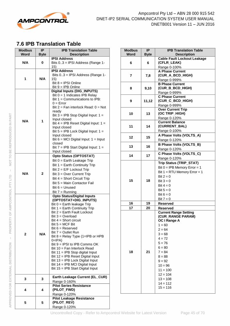
Ampcontrol Pty Ltd – ABN 28 000 915 542
DNET-IP2 SERIAL COMMUNICATION SYSTEM USER MANUAL
DNETB001 Version 11 – JUN 2016
Uncontrolled Copy - Refer to Ampcontrol Website for Latest Version Page 45 of 70
AP
PR
OV
ED
FO
R E
XT
ER
NA
L D
IST
RIB
UT
ION
– P
RO
PE
RT
Y O
F A
MP
CO
NT
RO
L P
TY
LT
D
–
NO
T T
O B
E R
EP
RO
DU
CE
D IN
PA
RT
7.6 IPB Translation TableModbus
Word IP
Byte IPB Translation Table
Description
N/A 0 IPSI Address
Bits 0..3 = IPSI Address (Range 1-15)
1 N/A
IPSI Address
Bits 0..3 = IPSI Address (Range 1-15) Bit 8 = IPSI Online Bit 9 = IPB Online
N/A 1
Digital Inputs (DIG_INPUTS)
Bit 0 = 1 Indicates IPB Relay Bit 1 = Communications to IPB: 0 = Error Bit 2 = Fan interlock Read: 0 = Not ready Bit 3 = IPB Stop Digital Input: 1 = Input closed Bit 4 = IPB Reset Digital Input: 1 = Input closed Bit 5 = IPB Lock Digital Input: 1 = Input closed Bit 6 = MCI Digital Input: 1 = Input closed Bit 7 = IPB Start Digital Input: 1 = Input closed
N/A 2
Opto Status (OPTOSTAT)
Bit 0 = Earth Leakage Trip
Bit 1 = Earth Continuity Trip
Bit 2 = E/F Lockout Trip
Bit 3 = Over Current Trip
Bit 4 = Short Circuit Trip
Bit 5 = Main Contactor Fail
Bit 6 = Unused
Bit 7 = Running
2 N/A
Opto Status/Digital Inputs (OPTOSTAT+DIG_INPUTS)
Bit 0 = Earth leakage Trip Bit 1 = Earth Continuity Trip Bit 2 = Earth Fault Lockout Bit 3 = Overload Bit 4 = Short circuit Bit 5 = MCF Bit Bit 6 = Reserved Bit 7 = Outlet Run Bit 8 = Relay Type (1=IPB or HPB 0=IPA) Bit 9 = IPSI to IPB Comms OK Bit 10 = Fan Interlock Read Bit 11 = IPB Stop digital Input Bit 12 = IPB Reset Digital Input Bit 13 = IPB Lock Digital Input Bit 14 = IPB MCI Digital Input Bit 15 = IPB Start Digital Input
3 3 Earth Leakage Current (EL_CUR)
Range 0-160%
4 4
Pilot Series Resistance (PILOT_FWD)
Range 0-120%
5 5
Pilot Leakage Resistance (PILOT_REV)
Range 0-120%
Modbus Word
IP Byte
IPB Translation Table Description
6 6
Cable Fault Lockout Leakage (CFLR_LEAK)
Range 0-100%
7 7,8
A Phase Current (CUR_A_BCD_HIGH)
Range 0-999%
8 9,10
B Phase Current (CUR_B_BCD_HIGH)
Range 0-999%
9 11,12
C Phase Current (CUR_C_BCD_HIGH)
Range 0-999%
10 13
Over Current Trip (OC TRIP_HIGH)
Range 0-120%
11 14
Current Balance (CURRENT_BAL)
Range 0-100%
12 15 A Phase Volts (VOLTS_A)
Range 0-120%
13 16 B Phase Volts (VOLTS_B)
Range 0-120%
14 17 C Phase Volts (VOLTS_C)
Range 0-120%
15 18
Trip Status (TRIP_STAT)
Bit 0 = IPB Memory Error = 1
Bit 1 = RTU Memory Error = 1
Bit 2 = 0
Bit 3 = 0
Bit 4 = 0
Bit 5 = 0
Bit 6 = 0
Bit 7 = 0
16 19 Reserved
17 20 Reserved
18 21
Current Range Setting (CUR_RANGE PARAM) OC I Range A
1 = 60
2 = 64
3 = 68
4 = 72
5 = 76
6 = 80
7 = 84
8 = 88
9 = 92
10 = 96
11 = 100
12 = 104
13 = 108
14 = 112 15 = 116

Ampcontrol Pty Ltd – ABN 28 000 915 542
DNET-IP2 SERIAL COMMUNICATION SYSTEM USER MANUAL
DNETB001 Version 11 – JUN 2016
Uncontrolled Copy - Refer to Ampcontrol Website for Latest Version Page 46 of 70
AP
PR
OV
ED
FO
R E
XT
ER
NA
L D
IST
RIB
UT
ION
– P
RO
PE
RT
Y O
F A
MP
CO
NT
RO
L P
TY
LT
D
–
NO
T T
O B
E R
EP
RO
DU
CE
D IN
PA
RT
Modbus Word
IP Byte
IPB Translation Table Description
19 22
Current Multiplier Setting (CUR_MUL_PARAM) OC I Mult
1 = 1/8
2 = ¼
3 = ½
4 = 1
5 = 2 6 = 4
20 23
Over Current Curve Setting (OC_CURVE_PARM) Curve Type
1 = Vinv 2 = m-OL
21 24
Over Current Time Multiplier (TIME_MULT_PARM) OC Time Multiplier
0 = ????
1 = 0.05
2 = 0.075
3 = 0.1
4 = 0.15
5 = 0.2
6 = 0.3
7 = 0.4
8 = 0.5
9 = 0.6
10 = 0.7
11 = 0.9
12 = 1.0
13 = 0.04
14 = 0.03
15 = 0.02
16 = 0.015
17 = 0.01 18 = 0.005
22 25
Cool Multiplier Setting (COOL_MUL_PARAM) Cool Mult
0 = ????
1 = 0.2
2 = 0.3
3 = 0.4
4 = 0.5
5 = 0.8
6 = 1.0
7 = 2.0
8 = 5.0
9 = 10
10 = 20 11 = 50
Modbus Word
IP Byte
IPB Translation Table Description
23 26
Current Balance Setting (CUR_BAL_PARAM) Cur Bal Trip%
0 = ????
1 = 5
2 = 10
3 = 20
4 = 50 5 = Off
24 27
Short Circuit Setting (SHORT_CCT_PARAM) SC I Trip Mult
0 = ????
1 = 3.0
2 = 3.5
3 = 4.0
4 = 4.5
5 = 5.0
6 = 5.5
7 = 6.0
8 = 6.5
9 = 7.0
10 = 7.5
11 = 8.0
12 = 8.5
13 = 9.0
14 = 9.5 15 = 10.0
25 28
Short Circuit Trip Time Setting (SC_TRP_TM_PARAM) SC Trip Time – ms
0 = ????
1 = 20
2 = 40
3 = 60
4 = 80 5 = 100
26 29
Short Circuit Output Relay Selection (SC_OUT_PARAM) SC Relay)
0 = ???
1 = CBR 2 = MCR
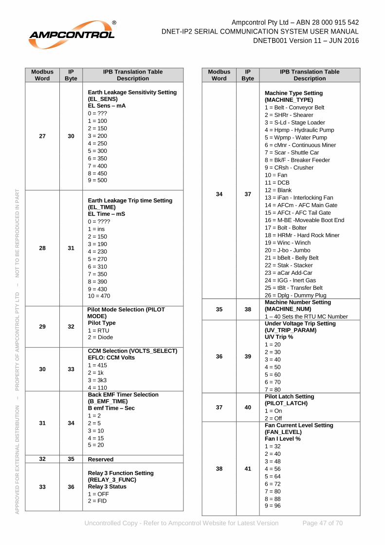
Ampcontrol Pty Ltd – ABN 28 000 915 542
DNET-IP2 SERIAL COMMUNICATION SYSTEM USER MANUAL
DNETB001 Version 11 – JUN 2016
Uncontrolled Copy - Refer to Ampcontrol Website for Latest Version Page 47 of 70
AP
PR
OV
ED
FO
R E
XT
ER
NA
L D
IST
RIB
UT
ION
– P
RO
PE
RT
Y O
F A
MP
CO
NT
RO
L P
TY
LT
D
–
NO
T T
O B
E R
EP
RO
DU
CE
D IN
PA
RT
Modbus Word
IP Byte
IPB Translation Table Description
27 30
Earth Leakage Sensitivity Setting (EL_SENS) EL Sens – mA
0 = ???
1 = 100
2 = 150
3 = 200
4 = 250
5 = 300
6 = 350
7 = 400
8 = 450 9 = 500
28 31
Earth Leakage Trip time Setting (EL_TIME) EL Time – mS
0 = ????
1 = ins
2 = 150
3 = 190
4 = 230
5 = 270
6 = 310
7 = 350
8 = 390
9 = 430 10 = 470
29 32
Pilot Mode Selection (PILOT MODE) Pilot Type
1 = RTU 2 = Diode
30 33
CCM Selection (VOLTS_SELECT) EFLO: CCM Volts
1 = 415
2 = 1k
3 = 3k3
4 = 110
31 34
Back EMF Timer Selection (B_EMF_TIME) B emf Time – Sec
1 = 2
2 = 5
3 = 10
4 = 15 5 = 20
32 35 Reserved
33 36
Relay 3 Function Setting (RELAY_3_FUNC) Relay 3 Status
1 = OFF 2 = FID
Modbus Word
IP Byte
IPB Translation Table Description
34 37
Machine Type Setting (MACHINE_TYPE)
1 = Belt - Conveyor Belt
2 = SHRr - Shearer
3 = S-Ld - Stage Loader
4 = Hpmp - Hydraulic Pump
5 = Wpmp - Water Pump
6 = cMnr - Continuous Miner
7 = Scar - Shuttle Car
8 = Bk/F - Breaker Feeder
9 = CRsh - Crusher
10 = Fan
11 = DCB
12 = Blank
13 = iFan - Interlocking Fan
14 = AFCm - AFC Main Gate
15 = AFCt - AFC Tail Gate
16 = M-BE -Moveable Boot End
17 = Bolt - Bolter
18 = HRMr - Hard Rock Miner
19 = Winc - Winch
20 = J-bo - Jumbo
21 = bBelt - Belly Belt
22 = Stak - Stacker
23 = aCar Add-Car
24 = IGG - Inert Gas
25 = tBlt - Transfer Belt
26 = Dplg - Dummy Plug
35 38
Machine Number Setting (MACHINE_NUM)
1 – 40 Sets the RTU MC Number
36 39
Under Voltage Trip Setting (UV_TRIP_PARAM) U/V Trip %
1 = 20
2 = 30
3 = 40
4 = 50
5 = 60
6 = 70
7 = 80
37 40
Pilot Latch Setting (PILOT_LATCH)
1 = On
2 = Off
38 41
Fan Current Level Setting (FAN_LEVEL) Fan I Level %
1 = 32
2 = 40
3 = 48
4 = 56
5 = 64
6 = 72
7 = 80
8 = 88 9 = 96

Ampcontrol Pty Ltd – ABN 28 000 915 542
DNET-IP2 SERIAL COMMUNICATION SYSTEM USER MANUAL
DNETB001 Version 11 – JUN 2016
Uncontrolled Copy - Refer to Ampcontrol Website for Latest Version Page 48 of 70
AP
PR
OV
ED
FO
R E
XT
ER
NA
L D
IST
RIB
UT
ION
– P
RO
PE
RT
Y O
F A
MP
CO
NT
RO
L P
TY
LT
D
–
NO
T T
O B
E R
EP
RO
DU
CE
D IN
PA
RT
Modbus Word
IP Byte
IPB Translation Table Description
39 42 RTU RTD1 Temperature
0 to 200 C, 255 = Offline
40 43 RTU RTD 2 Temperature
0 to 200 C, 255 = Offline
41 44 RTU RTD 3 Temperature
0 to 200 C, 255 = Offline
42 45 RTU RTD 4 Temperature
0 to 200 C, 255 = Offline
43 46 RTU CIU Data Byte 0
Range = 0-255, 255 = Offline
44 47 RTU CIU Data Byte 1
Range = 0-255, 255 = Offline
45 48
RTU Digital Inputs (RTU_DIG_IN)
Bit 0 = RTU Start: 0 = Closed
Bit 1 = RTU Stop: 0 = Closed
Bit 2 = RTU PTC: 0 = Closed
Bit 3 – 7 = 0
46 49
Relay Status (RELAT_STAT)
Bit 0 = RELAY 4 (closed if bit set) Bit 1 = CBR RELAY (closed if bit set) Bit 2 = MCR RELAY (closed if bit set) Bit 3 = RL3 RELAY (closed if bit set)
Bit 4 = Reserved Bit 5 = Fan Interlock Drive (on if bit is set)
Bit 6 = Reserved
Bit 7 = Reserved
47 50 Reserved
48 51
Remote Start Setting (REMOTE_CONTROL)
1 = No
2 = Yes
49 52 Reserved
50 53
Earth Continuity Time Delay Setting (ECTIME_ADJ) EC Time – ms
1 = 80
2 = 120
3 = 160
4 = 200
Modbus Word
IP Byte
IPB Translation Table Description
5 = 300
6 = 400
7 = 500
51 54 Reserved
52 55 Reserved
53 56 Reserved
54 57 RTU CIU Data Byte 2
Range = 0-255, 255 = Offline
55 58 RTU CIU Data Byte 3
Range = 0-255, 255 = Offline
56 59 RTU CIU Data Byte 4
Range = 0-255, 255 = Offline
57 60 RTU CIU Data Byte 5
Range = 0-255, 255 = Offline
58 61 RTU CIU Data Byte 6
Range = 0-255, 255 = Offline
59 62 RTU CIU Data Byte 7
Range = 0-255, 255 = Offline
60 63 Checksum (Low order byte of sum of all IP bytes

Ampcontrol Pty Ltd – ABN 28 000 915 542
DNET-IP2 SERIAL COMMUNICATION SYSTEM USER MANUAL
DNETB001 Version 11 – JUN 2016
Uncontrolled Copy - Refer to Ampcontrol Website for Latest Version Page 49 of 70
AP
PR
OV
ED
FO
R E
XT
ER
NA
L D
IST
RIB
UT
ION
– P
RO
PE
RT
Y O
F A
MP
CO
NT
RO
L P
TY
LT
D
–
NO
T T
O B
E R
EP
RO
DU
CE
D IN
PA
RT
7.7 IPA V4/5.1 Translation TableModbus
Word IP
Byte IPA 4/5 Translation Table
Description
1 1
Digital Inputs (DIG_INPUTS)
Bit 0 = 1 Indicates IPA Relay
Bit 1 = Communications to IPA: 0 = Error
Bit 2 = Fan interlock Read: 0 = Not ready
Bit 3 = IPA Stop Digital Input: 1 = Input closed
Bit 4 = IPA Reset Digital Input: 1 = Input closed
Bit 5 = IPA Lock Digital Input: 1 = Input closed
Bit 6 = MCI Digital Input: 1 = Input closed
Bit 7 = IPA Start Digital Input: 1 = Input closed
2 2
Opto Status (OPTOSTAT)
Bit 0 = Earth Leakage Trip
Bit 1 = Earth Continuity Trip
Bit 2 = E/F Lockout Trip
Bit 3 = Over Current Trip
Bit 4 = Short Circuit Trip
Bit 5 = Main Contactor Fail
Bit 6 = Unused
Bit 7 = Running
3 3
Earth Leakage Current (EL_CUR)
Range 0-160%
4 4
Pilot Series Resistance (PILOT_FWD)
Range 0-120%
5 5
Pilot Leakage Resistance (PILOT_REV)
Range 0-120%
6 6
Cable Fault Lockout Leakage (CFLR_LEAK)
Range 0-100%
7 7,8
A Phase Current (CUR_A_BCD_HIGH)
Range 0-999%
8 9, 10
B Phase Current (CUR_B_BCD_HIGH)
Range 0-999%
9 11, 12
C Phase Current (CUR_C_BCD_HIGH)
Range 0-999%
10 13
Over Current Trip (OC TRIP_HIGH)
Range 0-120%
11 14 Current Balance (CURRENT_BAL)
Range 0-100%
12 15 A Phase Volts (VOLTS_A)
Range 0-120%
13 16 B Phase Volts (VOLTS_B)
Range 0-120%
Modbus Word
IP Byte
IPA 4/5 Translation Table Description
14 17 C Phase Volts (VOLTS_C)
Range 0-120%
15 18
Trip Status (TRIP_STAT)
Bit 0 = IPB Memory Error = 1
Bit 1 = RTU Memory Error = 1
Bit 2 = 0
Bit 3 = 0
Bit 4 = 0
Bit 5 = 0
Bit 6 = 0
Bit 7 = 0
16 19 Reserved
17 20 Reserved
18 21
Current Range Setting (CUR_RANGE PARAM) OC I Range A
1 = 60
2 = 64
3 = 68
4 = 72
5 = 76
6 = 80
7 = 84
8 = 88
9 = 92
10 = 96
11 = 100
12 = 104
13 = 108
14 = 112
15 = 116
19 22
Current Multiplier Setting (CUR_MUL_PARAM) OC I Mult
1 = 1/8
2 = 1/4
3 = 1/2
4 = 1
5 = 2
6 = 4
20 23
Over Current Curve Setting (OC_CURVE_PARM) Curve Type
1 = Vinv
2 = m-OL

Ampcontrol Pty Ltd – ABN 28 000 915 542
DNET-IP2 SERIAL COMMUNICATION SYSTEM USER MANUAL
DNETB001 Version 11 – JUN 2016
Uncontrolled Copy - Refer to Ampcontrol Website for Latest Version Page 50 of 70
AP
PR
OV
ED
FO
R E
XT
ER
NA
L D
IST
RIB
UT
ION
– P
RO
PE
RT
Y O
F A
MP
CO
NT
RO
L P
TY
LT
D
–
NO
T T
O B
E R
EP
RO
DU
CE
D IN
PA
RT
Modbus Word
IP Byte
IPA 4/5 Translation Table Description
21 24
Over Current Time Multiplier (TIME_MULT_PARM) OC Time Multiplier
1 = 0.05
2 = 0.075
3 = 0.1
4 = 0.15
5 = 0.2
6 = 0.3
7 = 0.4
8 = 0.5
9 = 0.6
10 = 0.7
11 = 0.9
12 = 1.0
13 = 0.04
14 = 0.03
15 = 0.02
16 = 0.015
17 = 0.01 18 = 0.005
22 25
Cool Multiplier Setting (COOL_MUL_PARAM) Cool Mult
1 = 0.2
2 = 0.3
3 = 0.4
4 = 0.5
5 = 0.8
6 = 1.0
7 = 2.0
8 = 5.0
9 = 10
10 = 20 11 = 50
23 26
Current Balance Setting (CUR_BAL_PARAM) Cur Bal Trip%
1 = 5
2 = 10
3 = 20
4 = 50 5 = Off
Modbus Word
IP Byte
IPA 4/5 Translation Table Description
24 27
Short Circuit Setting (SHORT_CCT_PARAM) SC I Trip Mult
1 = 3.0
2 = 3.5
3 = 4.0
4 = 4.5
5 = 5.0
6 = 5.5
7 = 6.0
8 = 6.5
9 = 7.0
10 = 7.5
11 = 8.0
12 = 8.5
13 = 9.0
14 = 9.5
15 = 10.0
25 28
Short Circuit Trip Time Setting (SC_TRP_TM_PARAM) SC Trip Time – ms
1 = 20
2 = 40
3 = 60
4 = 80
5 = 100
26 29
Short Circuit Output Relay Selection (SC_OUT_PARAM) SC Relay)
1 = CBR
2 = MCR
27 30
Earth Leakage Sensitivity Setting (EL_SENS) EL Sens – mA
1 = 100
2 = 150
3 = 200
4 = 250
5 = 300
6 = 350
7 = 400
8 = 450
9 = 500
28 31
Earth Leakage Trip time Setting (EL_TIME) EL Time – ms
1 = ins
2 = 150
3 = 190
4 = 230
5 = 270
6 = 310
7 = 350
8 = 390
9 = 430 10 = 470
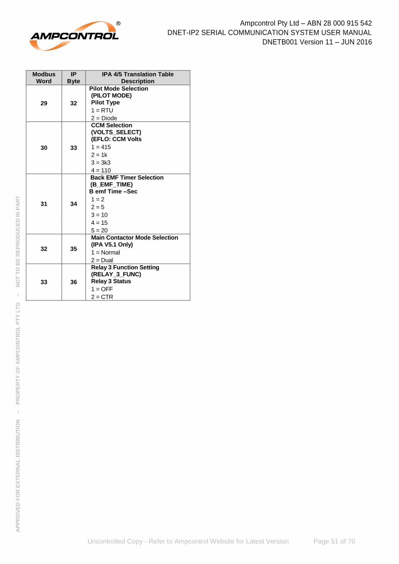
Ampcontrol Pty Ltd – ABN 28 000 915 542
DNET-IP2 SERIAL COMMUNICATION SYSTEM USER MANUAL
DNETB001 Version 11 – JUN 2016
Uncontrolled Copy - Refer to Ampcontrol Website for Latest Version Page 51 of 70
AP
PR
OV
ED
FO
R E
XT
ER
NA
L D
IST
RIB
UT
ION
– P
RO
PE
RT
Y O
F A
MP
CO
NT
RO
L P
TY
LT
D
–
NO
T T
O B
E R
EP
RO
DU
CE
D IN
PA
RT
Modbus Word
IP Byte
IPA 4/5 Translation Table Description
29 32
Pilot Mode Selection (PILOT MODE) Pilot Type
1 = RTU
2 = Diode
30 33
CCM Selection (VOLTS_SELECT) (EFLO: CCM Volts
1 = 415
2 = 1k
3 = 3k3
4 = 110
31 34
Back EMF Timer Selection (B_EMF_TIME) B emf Time –Sec
1 = 2
2 = 5
3 = 10
4 = 15
5 = 20
32 35
Main Contactor Mode Selection (IPA V5.1 Only)
1 = Normal
2 = Dual
33 36
Relay 3 Function Setting (RELAY_3_FUNC) Relay 3 Status
1 = OFF
2 = CTR

Ampcontrol Pty Ltd – ABN 28 000 915 542
DNET-IP2 SERIAL COMMUNICATION SYSTEM USER MANUAL
DNETB001 Version 11 – JUN 2016
Uncontrolled Copy - Refer to Ampcontrol Website for Latest Version Page 52 of 70
AP
PR
OV
ED
FO
R E
XT
ER
NA
L D
IST
RIB
UT
ION
– P
RO
PE
RT
Y O
F A
MP
CO
NT
RO
L P
TY
LT
D
–
NO
T T
O B
E R
EP
RO
DU
CE
D IN
PA
RT
8 SERVICE, MAINTENANCE & DISPOSAL
8.1 Equipment Service
A number of external system based checks should be completed on a regular basis. These ‘routine inspections’ must be carried out by suitably trained people with knowledge of the DNET-IP2 Serial Communication System and the systems into which it is fitted. Routine inspections may take the form of either visual-only checks, or visual and ‘hands-on’ checks.
8.1.1 Visual Only Inspections
A basic visual inspection focuses on looking at the installation for signs of physical damage, water or dust ingress and the condition of cables and labels. This type of inspection may involve opening cabinets to gain access to the System and other equipment. This level of inspection may also include cleaning display windows that have become obscured by dirt.
Observations would typically be:
Check that equipment enclosures, cable trays, conduits, etc. are in good order with no physical damage.
Check that sealed wall boxes are free from water and dust ingress internally. Door seals are in good condition.
Check that connected cables are free from cuts, abrasions and obvious signs of damage. Cable restraints are in good order and correctly fitted.
Check that labels on equipment, wall boxes and cables are present and in good condition (especially certification labels).
Check that no modifications have been carried out to installed equipment.
8.1.2 Hands-On (Detailed) Inspections
A more detailed inspection would include all of the elements of a visual inspection, plus some checks that cover the integrity of connections, fixtures and fittings.
In addition to basic visual observations, more detailed integrity checks would involve:
Verify that equipment housings, wall boxes and other mechanical fixtures are secured in place. This includes terminal box lids, tightness of cable glands, integrity of wall-box mountings, security of equipment fixing to walls/DIN rails etc.
Verify all electrical connections are secure with no loose screw terminals or DIN rail terminals not fitted to rails etc.

Ampcontrol Pty Ltd – ABN 28 000 915 542
DNET-IP2 SERIAL COMMUNICATION SYSTEM USER MANUAL
DNETB001 Version 11 – JUN 2016
Uncontrolled Copy - Refer to Ampcontrol Website for Latest Version Page 53 of 70
AP
PR
OV
ED
FO
R E
XT
ER
NA
L D
IST
RIB
UT
ION
– P
RO
PE
RT
Y O
F A
MP
CO
NT
RO
L P
TY
LT
D
–
NO
T T
O B
E R
EP
RO
DU
CE
D IN
PA
RT
8.2 Equipment Maintenance
WARNING!
The DNET-IP2 Serial Communication System has no user-serviceable parts.
All repairs must be carried out by Ampcontrol only.
If a fault develops, return the product to Ampcontrol for repair. It is essential that no attempt be made to repair the product as any
attempt to dismantle or repair the product can seriously compromise the safety of the unit and voids product warranty.
8.3 Disposal
ENVIRO
The electronic equipment discussed in this manual must not be treated as general waste. By ensuring that this product is disposed of
correctly you will be helping to prevent potentially negative consequences for the environment which could otherwise be caused by
incorrect waste handling of this product.
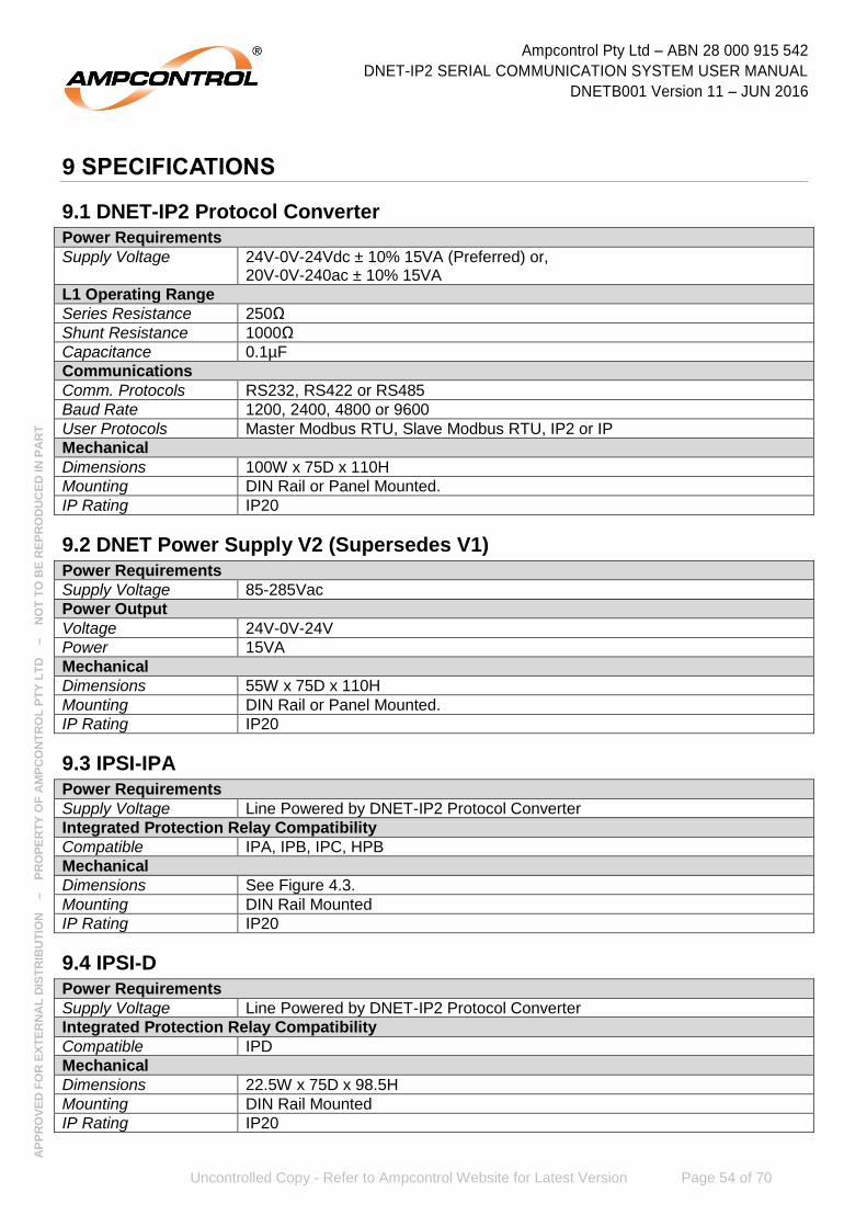
Ampcontrol Pty Ltd – ABN 28 000 915 542
DNET-IP2 SERIAL COMMUNICATION SYSTEM USER MANUAL
DNETB001 Version 11 – JUN 2016
Uncontrolled Copy - Refer to Ampcontrol Website for Latest Version Page 54 of 70
AP
PR
OV
ED
FO
R E
XT
ER
NA
L D
IST
RIB
UT
ION
– P
RO
PE
RT
Y O
F A
MP
CO
NT
RO
L P
TY
LT
D
–
NO
T T
O B
E R
EP
RO
DU
CE
D IN
PA
RT
9 SPECIFICATIONS
9.1 DNET-IP2 Protocol Converter
Power Requirements
Supply Voltage 24V-0V-24Vdc ± 10% 15VA (Preferred) or, 20V-0V-240ac ± 10% 15VA
L1 Operating Range
Series Resistance 250Ω
Shunt Resistance 1000Ω
Capacitance 0.1µF
Communications
Comm. Protocols RS232, RS422 or RS485
Baud Rate 1200, 2400, 4800 or 9600
User Protocols Master Modbus RTU, Slave Modbus RTU, IP2 or IP
Mechanical
Dimensions 100W x 75D x 110H
Mounting DIN Rail or Panel Mounted.
IP Rating IP20
9.2 DNET Power Supply V2 (Supersedes V1)
Power Requirements
Supply Voltage 85-285Vac
Power Output
Voltage 24V-0V-24V
Power 15VA
Mechanical
Dimensions 55W x 75D x 110H
Mounting DIN Rail or Panel Mounted.
IP Rating IP20
9.3 IPSI-IPA
Power Requirements
Supply Voltage Line Powered by DNET-IP2 Protocol Converter
Integrated Protection Relay Compatibility
Compatible IPA, IPB, IPC, HPB
Mechanical
Dimensions See Figure 4.3.
Mounting DIN Rail Mounted
IP Rating IP20
9.4 IPSI-D
Power Requirements
Supply Voltage Line Powered by DNET-IP2 Protocol Converter
Integrated Protection Relay Compatibility
Compatible IPD
Mechanical
Dimensions 22.5W x 75D x 98.5H
Mounting DIN Rail Mounted
IP Rating IP20

Ampcontrol Pty Ltd – ABN 28 000 915 542
DNET-IP2 SERIAL COMMUNICATION SYSTEM USER MANUAL
DNETB001 Version 11 – JUN 2016
Uncontrolled Copy - Refer to Ampcontrol Website for Latest Version Page 55 of 70
AP
PR
OV
ED
FO
R E
XT
ER
NA
L D
IST
RIB
UT
ION
– P
RO
PE
RT
Y O
F A
MP
CO
NT
RO
L P
TY
LT
D
–
NO
T T
O B
E R
EP
RO
DU
CE
D IN
PA
RT
10 EQUIPMENT LIST
Part Number Description
101270 DNET-IP2 Protocol Converter
171107 DNET-IP2 Power Supply 85-285Vac V2
101501 IPSI-IPA Serial Interface Module
110144 IPSI-D IPD Serial Interface Module
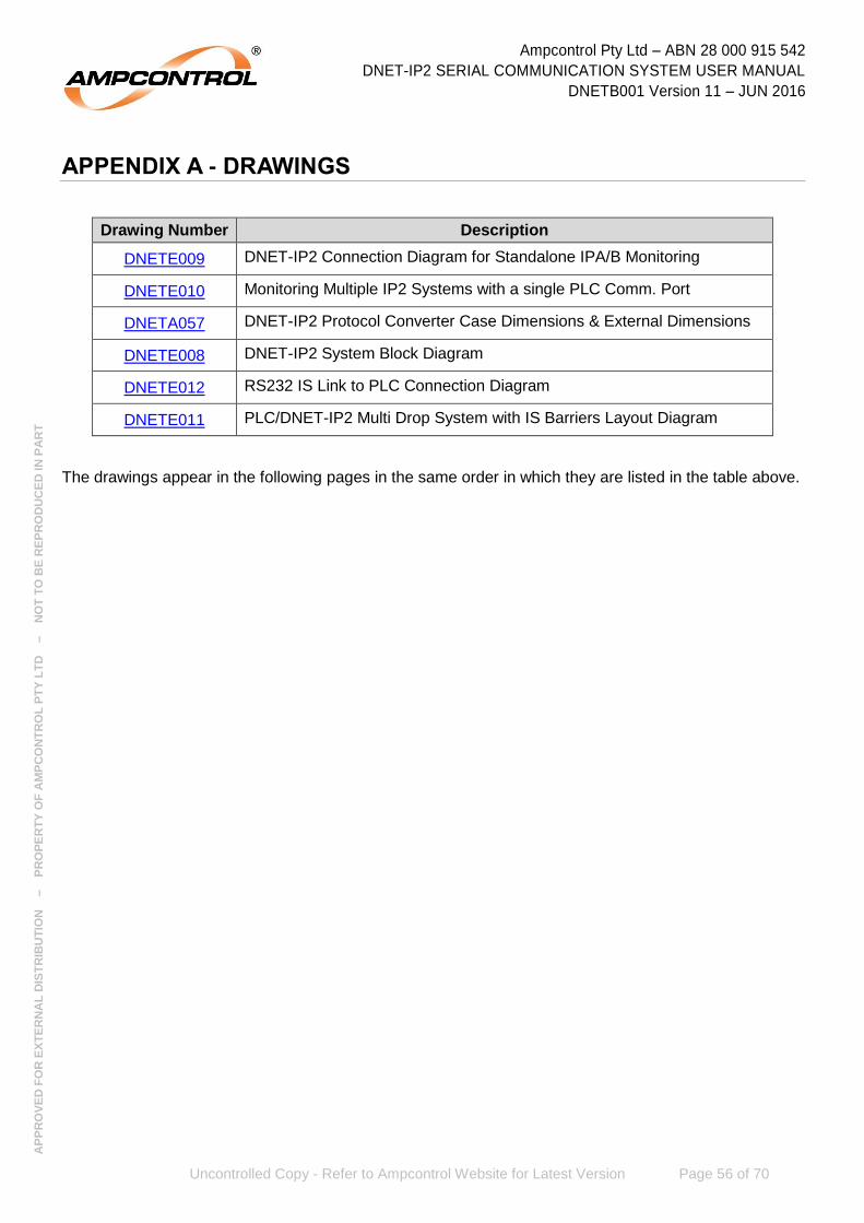
Ampcontrol Pty Ltd – ABN 28 000 915 542
DNET-IP2 SERIAL COMMUNICATION SYSTEM USER MANUAL
DNETB001 Version 11 – JUN 2016
Uncontrolled Copy - Refer to Ampcontrol Website for Latest Version Page 56 of 70
AP
PR
OV
ED
FO
R E
XT
ER
NA
L D
IST
RIB
UT
ION
– P
RO
PE
RT
Y O
F A
MP
CO
NT
RO
L P
TY
LT
D
–
NO
T T
O B
E R
EP
RO
DU
CE
D IN
PA
RT
APPENDIX A - DRAWINGS
Drawing Number Description
DNETE009 DNET-IP2 Connection Diagram for Standalone IPA/B Monitoring
DNETE010 Monitoring Multiple IP2 Systems with a single PLC Comm. Port
DNETA057 DNET-IP2 Protocol Converter Case Dimensions & External Dimensions
DNETE008 DNET-IP2 System Block Diagram
DNETE012 RS232 IS Link to PLC Connection Diagram
DNETE011 PLC/DNET-IP2 Multi Drop System with IS Barriers Layout Diagram
The drawings appear in the following pages in the same order in which they are listed in the table above.
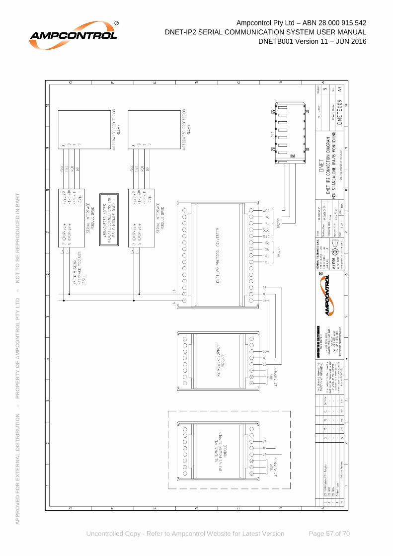
Ampcontrol Pty Ltd – ABN 28 000 915 542
DNET-IP2 SERIAL COMMUNICATION SYSTEM USER MANUAL
DNETB001 Version 11 – JUN 2016
Uncontrolled Copy - Refer to Ampcontrol Website for Latest Version Page 57 of 70
AP
PR
OV
ED
FO
R E
XT
ER
NA
L D
IST
RIB
UT
ION
– P
RO
PE
RT
Y O
F A
MP
CO
NT
RO
L P
TY
LT
D
–
NO
T T
O B
E R
EP
RO
DU
CE
D IN
PA
RT

Ampcontrol Pty Ltd – ABN 28 000 915 542
DNET-IP2 SERIAL COMMUNICATION SYSTEM USER MANUAL
DNETB001 Version 11 – JUN 2016
Uncontrolled Copy - Refer to Ampcontrol Website for Latest Version Page 58 of 70
AP
PR
OV
ED
FO
R E
XT
ER
NA
L D
IST
RIB
UT
ION
– P
RO
PE
RT
Y O
F A
MP
CO
NT
RO
L P
TY
LT
D
–
NO
T T
O B
E R
EP
RO
DU
CE
D IN
PA
RT

Ampcontrol Pty Ltd – ABN 28 000 915 542
DNET-IP2 SERIAL COMMUNICATION SYSTEM USER MANUAL
DNETB001 Version 11 – JUN 2016
Uncontrolled Copy - Refer to Ampcontrol Website for Latest Version Page 59 of 70
AP
PR
OV
ED
FO
R E
XT
ER
NA
L D
IST
RIB
UT
ION
– P
RO
PE
RT
Y O
F A
MP
CO
NT
RO
L P
TY
LT
D
–
NO
T T
O B
E R
EP
RO
DU
CE
D IN
PA
RT

Ampcontrol Pty Ltd – ABN 28 000 915 542
DNET-IP2 SERIAL COMMUNICATION SYSTEM USER MANUAL
DNETB001 Version 11 – JUN 2016
Uncontrolled Copy - Refer to Ampcontrol Website for Latest Version Page 60 of 70
AP
PR
OV
ED
FO
R E
XT
ER
NA
L D
IST
RIB
UT
ION
– P
RO
PE
RT
Y O
F A
MP
CO
NT
RO
L P
TY
LT
D
–
NO
T T
O B
E R
EP
RO
DU
CE
D IN
PA
RT

Ampcontrol Pty Ltd – ABN 28 000 915 542
DNET-IP2 SERIAL COMMUNICATION SYSTEM USER MANUAL
DNETB001 Version 11 – JUN 2016
Uncontrolled Copy - Refer to Ampcontrol Website for Latest Version Page 61 of 70
AP
PR
OV
ED
FO
R E
XT
ER
NA
L D
IST
RIB
UT
ION
– P
RO
PE
RT
Y O
F A
MP
CO
NT
RO
L P
TY
LT
D
–
NO
T T
O B
E R
EP
RO
DU
CE
D IN
PA
RT
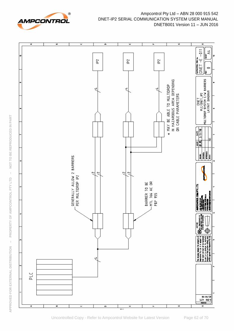
Ampcontrol Pty Ltd – ABN 28 000 915 542
DNET-IP2 SERIAL COMMUNICATION SYSTEM USER MANUAL
DNETB001 Version 11 – JUN 2016
Uncontrolled Copy - Refer to Ampcontrol Website for Latest Version Page 62 of 70
AP
PR
OV
ED
FO
R E
XT
ER
NA
L D
IST
RIB
UT
ION
– P
RO
PE
RT
Y O
F A
MP
CO
NT
RO
L P
TY
LT
D
–
NO
T T
O B
E R
EP
RO
DU
CE
D IN
PA
RT
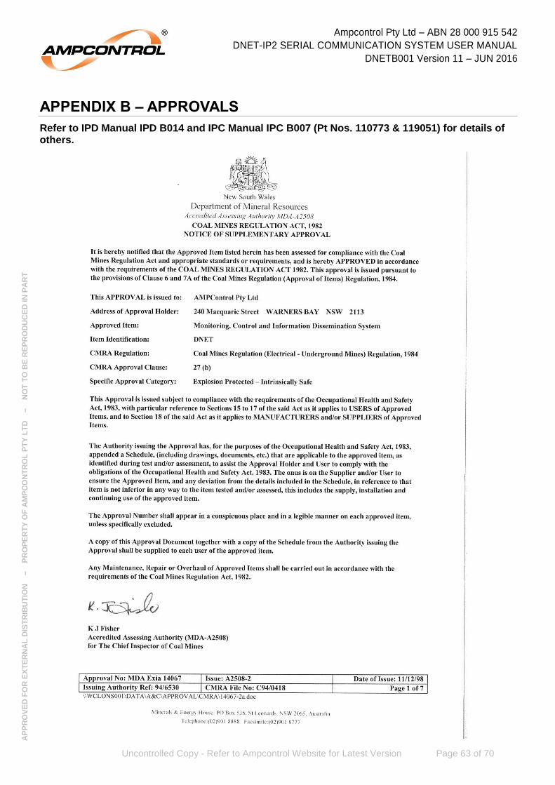
Ampcontrol Pty Ltd – ABN 28 000 915 542
DNET-IP2 SERIAL COMMUNICATION SYSTEM USER MANUAL
DNETB001 Version 11 – JUN 2016
Uncontrolled Copy - Refer to Ampcontrol Website for Latest Version Page 63 of 70
AP
PR
OV
ED
FO
R E
XT
ER
NA
L D
IST
RIB
UT
ION
– P
RO
PE
RT
Y O
F A
MP
CO
NT
RO
L P
TY
LT
D
–
NO
T T
O B
E R
EP
RO
DU
CE
D IN
PA
RT
APPENDIX B – APPROVALS
Refer to IPD Manual IPD B014 and IPC Manual IPC B007 (Pt Nos. 110773 & 119051) for details of others.

Ampcontrol Pty Ltd – ABN 28 000 915 542
DNET-IP2 SERIAL COMMUNICATION SYSTEM USER MANUAL
DNETB001 Version 11 – JUN 2016
Uncontrolled Copy - Refer to Ampcontrol Website for Latest Version Page 64 of 70
AP
PR
OV
ED
FO
R E
XT
ER
NA
L D
IST
RIB
UT
ION
– P
RO
PE
RT
Y O
F A
MP
CO
NT
RO
L P
TY
LT
D
–
NO
T T
O B
E R
EP
RO
DU
CE
D IN
PA
RT

Ampcontrol Pty Ltd – ABN 28 000 915 542
DNET-IP2 SERIAL COMMUNICATION SYSTEM USER MANUAL
DNETB001 Version 11 – JUN 2016
Uncontrolled Copy - Refer to Ampcontrol Website for Latest Version Page 65 of 70
AP
PR
OV
ED
FO
R E
XT
ER
NA
L D
IST
RIB
UT
ION
– P
RO
PE
RT
Y O
F A
MP
CO
NT
RO
L P
TY
LT
D
–
NO
T T
O B
E R
EP
RO
DU
CE
D IN
PA
RT
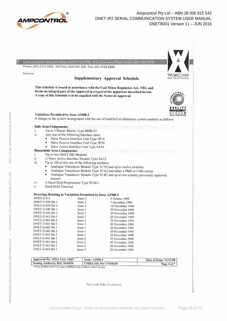
Ampcontrol Pty Ltd – ABN 28 000 915 542
DNET-IP2 SERIAL COMMUNICATION SYSTEM USER MANUAL
DNETB001 Version 11 – JUN 2016
Uncontrolled Copy - Refer to Ampcontrol Website for Latest Version Page 66 of 70
AP
PR
OV
ED
FO
R E
XT
ER
NA
L D
IST
RIB
UT
ION
– P
RO
PE
RT
Y O
F A
MP
CO
NT
RO
L P
TY
LT
D
–
NO
T T
O B
E R
EP
RO
DU
CE
D IN
PA
RT
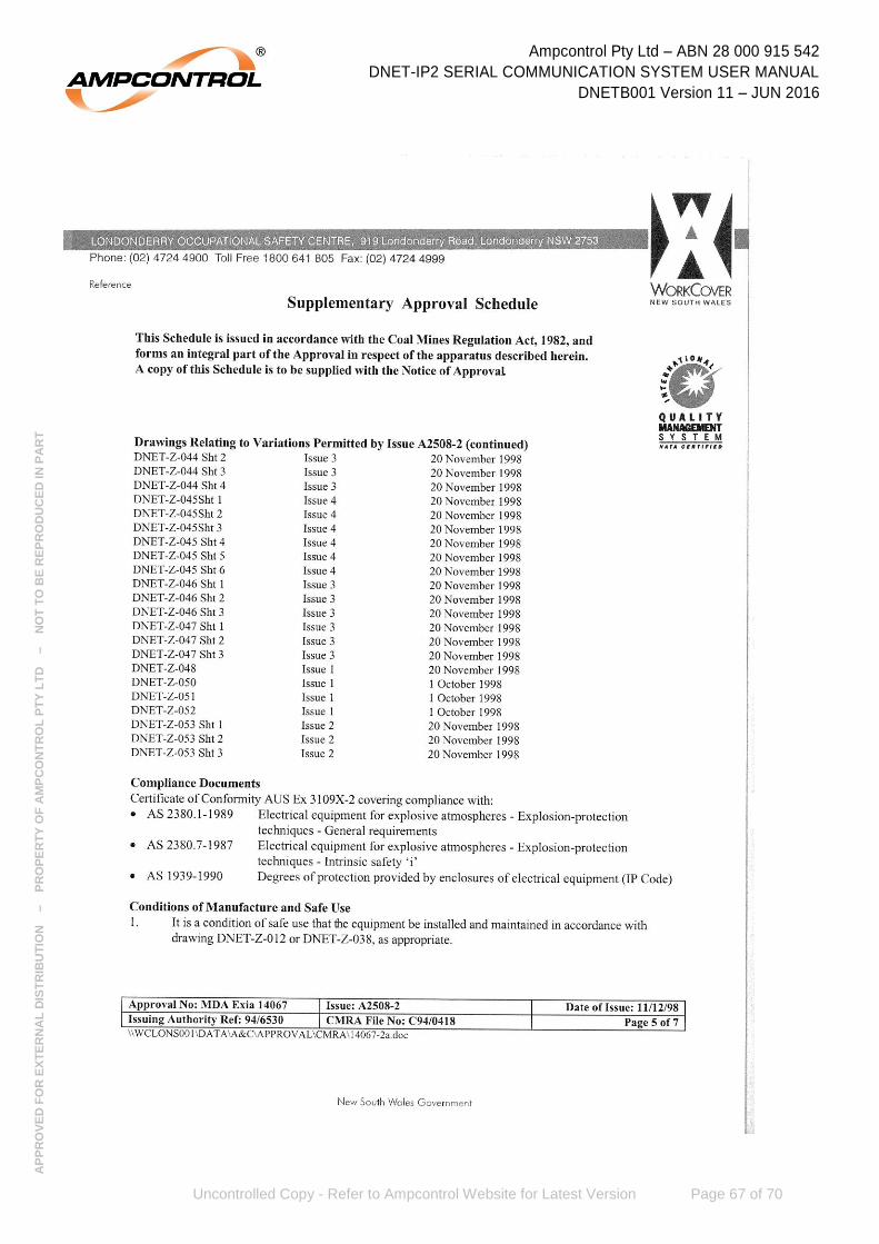
Ampcontrol Pty Ltd – ABN 28 000 915 542
DNET-IP2 SERIAL COMMUNICATION SYSTEM USER MANUAL
DNETB001 Version 11 – JUN 2016
Uncontrolled Copy - Refer to Ampcontrol Website for Latest Version Page 67 of 70
AP
PR
OV
ED
FO
R E
XT
ER
NA
L D
IST
RIB
UT
ION
– P
RO
PE
RT
Y O
F A
MP
CO
NT
RO
L P
TY
LT
D
–
NO
T T
O B
E R
EP
RO
DU
CE
D IN
PA
RT

Ampcontrol Pty Ltd – ABN 28 000 915 542
DNET-IP2 SERIAL COMMUNICATION SYSTEM USER MANUAL
DNETB001 Version 11 – JUN 2016
Uncontrolled Copy - Refer to Ampcontrol Website for Latest Version Page 68 of 70
AP
PR
OV
ED
FO
R E
XT
ER
NA
L D
IST
RIB
UT
ION
– P
RO
PE
RT
Y O
F A
MP
CO
NT
RO
L P
TY
LT
D
–
NO
T T
O B
E R
EP
RO
DU
CE
D IN
PA
RT
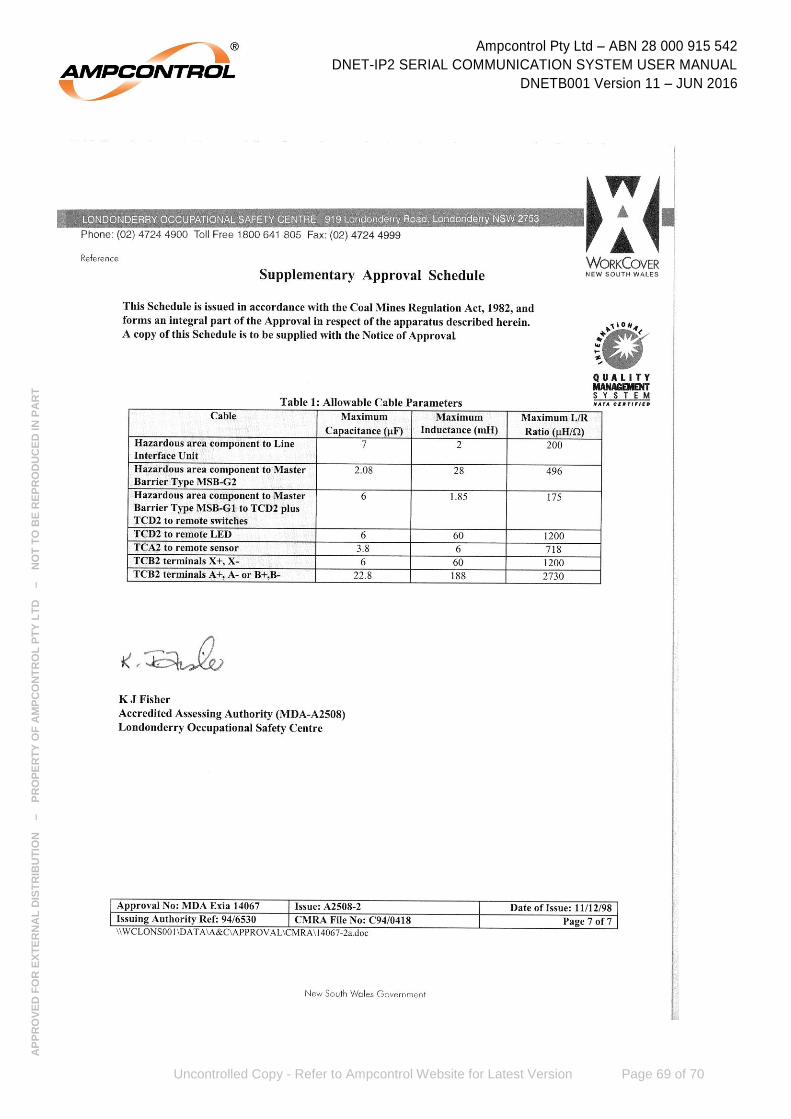
Ampcontrol Pty Ltd – ABN 28 000 915 542
DNET-IP2 SERIAL COMMUNICATION SYSTEM USER MANUAL
DNETB001 Version 11 – JUN 2016
Uncontrolled Copy - Refer to Ampcontrol Website for Latest Version Page 69 of 70
AP
PR
OV
ED
FO
R E
XT
ER
NA
L D
IST
RIB
UT
ION
– P
RO
PE
RT
Y O
F A
MP
CO
NT
RO
L P
TY
LT
D
–
NO
T T
O B
E R
EP
RO
DU
CE
D IN
PA
RT

Ampcontrol Pty Ltd – ABN 28 000 915 542
DNET-IP2 SERIAL COMMUNICATION SYSTEM USER MANUAL
DNETB001 Version 11 – JUN 2016
Uncontrolled Copy - Refer to Ampcontrol Website for Latest Version Page 70 of 70
AP
PR
OV
ED
FO
R E
XT
ER
NA
L D
IST
RIB
UT
ION
– P
RO
PE
RT
Y O
F A
MP
CO
NT
RO
L P
TY
LT
D
–
NO
T T
O B
E R
EP
RO
DU
CE
D IN
PA
RT
APPENDIX C- RISK & RELIABILITY