dnvgl-cp-0069 welding consumables
TRANSCRIPT

The electronic pdf version of this document, available free of chargefrom http://www.dnvgl.com, is the officially binding version.
DNV GL AS
CLASS PROGRAMME
Type approval
DNVGL-CP-0069 Edition March 2016
Welding consumables
FOREWORD
DNV GL class programmes contain procedural and technical requirements including acceptancecriteria for obtaining and retaining certificates for objects and organisations related toclassification.
© DNV GL AS March 2016
Any comments may be sent by e-mail to [email protected]
This service document has been prepared based on available knowledge, technology and/or information at the time of issuance of thisdocument. The use of this document by others than DNV GL is at the user's sole risk. DNV GL does not accept any liability or responsibilityfor loss or damages resulting from any use of this document.

Cha
nges
- c
urre
nt
Class programme — DNVGL-CP-0069. Edition March 2016 Page 3Welding consumables
DNV GL AS
CHANGES – CURRENT
This is a new document.

Con
tent
s
Class programme — DNVGL-CP-0069. Edition March 2016 Page 4Welding consumables
DNV GL AS
CONTENTS
Changes – current.................................................................................................. 3
Section 1 Scope.......................................................................................................81 General................................................................................................ 8
Section 2 Type approval..........................................................................................91 Procedure............................................................................................ 92 Application for type approval.............................................................. 93 The main elements of a DNV GL initial survey are:.............................. 94 Assessment of survey report and type test results..............................95 Issuance of type approval certificates.................................................96 Certificate retention survey (annual testing).......................................97 Application for renewal after five (5) years.......................................108 Documentation and information to be submitted...............................10
Section 3 Approval testing.................................................................................... 111 General.............................................................................................. 112 Changes............................................................................................. 113 Testing procedure..............................................................................114 Test specimens.................................................................................. 115 Fillet weld test...................................................................................146 Welding consumables for corrosion resistant steel for oil cargotanks.....................................................................................................167 Welding consumables with qualified CTOD properties....................... 168 Re-testing.......................................................................................... 16
Section 4 Covered electrodes for shielded metal arc welding of normal andhigh strength steels..............................................................................................18
1 General.............................................................................................. 182 All-weld-metal test............................................................................ 183 Butt-weld test....................................................................................194 Covered electrodes for gravity or contact welding.............................225 Deep penetration electrodes..............................................................226 Annual test........................................................................................ 247 Upgrading and uprating.....................................................................24
Section 5 Wire/flux combinations for submerged arc welding..............................261 General.............................................................................................. 26

Con
tent
s
Class programme — DNVGL-CP-0069. Edition March 2016 Page 5Welding consumables
DNV GL AS
2 Multi-run technique........................................................................... 263 Two-run technique.............................................................................304 Annual tests.......................................................................................315 Upgrading and uprating.....................................................................31
Section 6 Combinations for use in one-side automatic welding processes............ 331 General.............................................................................................. 332 One-run welding................................................................................ 333 Multi-run welding.............................................................................. 334 One-and multi-run welding................................................................345 Testing requirements.........................................................................356 Annual tests.......................................................................................367 Upgrading and uprating.....................................................................36
Section 7 Wires and wire and gas combinations for gas metal arc welding...........371 General.............................................................................................. 372 Semi-automatic multi-run welding.................................................... 373 Automatic multi-run welding............................................................. 394 Two-run welding................................................................................415 Annual test........................................................................................ 426 Upgrading and uprating.....................................................................43
Section 8 Combinations for use in electro-slag and electro-gas weldingprocesses..............................................................................................................44
1 General.............................................................................................. 442 Initial test..........................................................................................443 Annual test........................................................................................ 464 Upgrading and uprating.....................................................................46
Section 9 Welding consumables for welding of steel grades VL 2-4, VL 2-4L, VL4-4 and VL 4-4L for low-temperature...................................................................47
1 General.............................................................................................. 472 Additional requirements.................................................................... 473 Annual test........................................................................................ 47
Section 10 Welding consumables for low-alloy, heat-resisting steels (VL 0.3Mo,VL 1Cr 0.5Mo and VL 2.25Cr 1Mo)........................................................................49
1 General.............................................................................................. 492 All weld metal test............................................................................ 493 Butt weld test....................................................................................504 Chemical composition........................................................................ 51

Con
tent
s
Class programme — DNVGL-CP-0069. Edition March 2016 Page 6Welding consumables
DNV GL AS
5 Annual test........................................................................................ 51
Section 11 Welding consumables for welding of steel grades VL 1.5Ni; VL3.5Ni; VL 5Ni and VL 9Ni......................................................................................53
1 General.............................................................................................. 532 All-weld-metal test:........................................................................... 533 Butt-weld test:...................................................................................534 Annual test........................................................................................ 545 Other welding consumables...............................................................54
Section 12 Welding consumables for welding of extra high strength steels.......... 551 General.............................................................................................. 552 Annual tests.......................................................................................57
Section 13 Welding consumables for welding of austenitic and non-magneticstainless steels..................................................................................................... 58
1 General.............................................................................................. 582 All-weld-metal test............................................................................ 583 Butt weld test:...................................................................................594 Chemical composition........................................................................ 595 Corrosion Test................................................................................... 606 Austenitic welding consumables for welding of non-magneticstainless steels..................................................................................... 627 Annual test........................................................................................ 63
Section 14 Welding consumables for welding of ferritic-austenitic stainlesssteels (duplex steels)........................................................................................... 64
1 General.............................................................................................. 642 All weld metal test............................................................................ 643 Butt weld test....................................................................................644 Chemical composition........................................................................ 655 Microstructural examination.............................................................. 656 Corrosion test.................................................................................... 657 Annual tests.......................................................................................65
Section 15 Welding consumables for welding of aluminium alloys for generaland low-temperature service................................................................................66
1 General.............................................................................................. 662 Deposited weld metal test.................................................................663 Butt weld test....................................................................................664 Annual tests.......................................................................................68
Con
tent
s
Class programme — DNVGL-CP-0069. Edition March 2016 Page 7Welding consumables
DNV GL AS
Section 16 Welding consumables for copper and copper alloys............................ 691 General.............................................................................................. 692 All weld metal test............................................................................ 693 Butt weld test....................................................................................694 Chemical composition........................................................................ 705 The chemical composition shall not exceed the limits specified bythe manufacturer. Annual tests............................................................70
Section 17 Welding consumables for nickel and nickel alloys............................... 711 General.............................................................................................. 712 All weld metal test............................................................................ 713 Butt weld test....................................................................................714 Chemical composition........................................................................ 715 Annual test........................................................................................ 71
Section 18 Standards referred to in this document...............................................731 Referred standards............................................................................ 73
Changes – historic................................................................................................74
Sec
tion
1
Class programme — DNVGL-CP-0069. Edition March 2016 Page 8Welding consumables
DNV GL AS
SECTION 1 SCOPE
1 GeneralThis type approval programme specifies the requirements to be complied with for obtaining, maintainingand renewing the Society's type approval of welding consumables for welding of normal, high and extrahigh strength steels, boiler and pressure vessel steels, steels for low temperature service, austeniticstainless steels, duplex steels, aluminium alloys, copper and copper alloys, and nickel and nickel alloys. Thisprogramme covers IACS UR W17, W23, W26 and W31.Class programme DNVGL CP 0338 DNV GL type approval scheme, describes the type approval in general.Type approved products will be listed in the Society's register of type approved products available on the DNVGL internet site.

Sec
tion
2
Class programme — DNVGL-CP-0069. Edition March 2016 Page 9Welding consumables
DNV GL AS
SECTION 2 TYPE APPROVAL
1 ProcedureThe type approval procedure normally consists of the following steps:
— application for type approval— quotation— assessment of type approval documentation— initial survey of product and production facilities including witnessing of welding and type tests— assessment of survey report and type test results— issuance of type approval certificates— annual certificate retention surveys— application for renewal after five (5) years.
2 Application for type approvalThe type approval shall be applied for in writing to Society's local office. The application shall include typeapproval documentation as specified in [8].
3 The main elements of a DNV GL initial survey are:An initial survey will be carried out with the intention to confirm that:
— manufacturer has established a production line and quality control for consistent production— documentation that is the basis for the TA is representative for the manufacturing of the product— use of subcontractors is handled in a controlled manner— manufacturer or the holder of certificate takes the responsibility for the complete product delivered.
All test assemblies shall be prepared under the supervision of the surveyor, and all tests shall be carried outin his presence.When welding consumables are manufactured in several factories of the same company, the completeseries of approval tests shall at least be carried out in one of the works. In the other factories, a reducedtest programme, at least equivalent to annual tests and including hydrogen testing for low hydrogen typeconsumables, may be permitted if the manufacturer can verify that the materials used and the fabricationprocess are identical with those used at the main works. This requirement is applicable to all manufacturersof filler products under licence (sister firms). However, the Society may require complete test-series whenfound necessary.The manufacturers documentation and reports relevant for the type approval shall be signed by staff incharge at the manufacturer.
4 Assessment of survey report and type test resultsThe initial survey report and type test results will be assessed in order to verify compliance with therequirements.
5 Issuance of type approval certificatesWhen the assessment of type approval documentation, type testing and survey of production and qualitycontrol arrangement is successfully completed, a type approval certificate will be issued to the manufacturerof the product. The certificate is normally given a validity period of five (5) years, with annual certificateretention surveys.

Sec
tion
2
Class programme — DNVGL-CP-0069. Edition March 2016 Page 10Welding consumables
DNV GL AS
6 Certificate retention survey (annual testing)The main objective of the annual certificate retention survey is to verify that the production process ofwelding consumables and the product marking are not altered since issuance of the type approval certificate,and shall ensure that the type approval documentation is available.All approved welding consumables shall be subjected to a retention survey, which is usually performed bythe local DNV GL office. The retention survey shall be carried out not later than 3 months from anniversarydate. On these occasions, samples of the approved consumables shall be selected by the surveyor andsubjected to the tests detailed in subsequent sections of this document. Testing of welding consumables shallbe witnessed by the surveyor.Use of a manufacturer's quality assurance system as an alternative to retention survey may be acceptedafter agreement with the Society.The certificate retention survey report shall conclude that either:
a) the type approval certificate shall be retained, orb) the type approval certificate shall be modified or recalled due to the changes in the basis for the
approval.
7 Application for renewal after five (5) yearsApplication for renewal shall be submitted to the Society’s local office no later than three (3) months beforeexpiry date of the type approval certificate.The application shall include updated type approval documentation where changes have been implementedsince last issuance of the type approval.Upon receipt of the application, the Society will perform a renewal survey with main objective to verifythat the production process and the product marking are not altered since issuance of the type approvalcertificate. The renewal survey comprises of a works inspection and testing. The scope of testing will be asfor a normal annual certificate retention survey.Certificate renewal survey shall be carried out no later than five (5) years after issuance of the type approvalcertificate.If there, since last issuance of the type approval certificate, have been any relevant changes in the applicablerules and standards, a corresponding new assessment of products and type tests will be required.
8 Documentation and information to be submittedThe information relevant to the manufacturing of the welding consumables to be covered by the typeapproval certificate shall be submitted with the application for type approval.The language of the submitted documentation shall be English.
8.1 General manufacturer informationThe following general manufacturer information shall be submitted:
— an outline of the organisation structure including quality control responsibilities— manufacturing process description, visualized in flow chart(s) indicating all process steps— a list of the manufacturers written procedures for testing and inspection. The procedures need not to be
submitted, but shall be available for review at the manufacturer’s works upon request— procedure for product identification and traceability (including test samples).

Sec
tion
3
Class programme — DNVGL-CP-0069. Edition March 2016 Page 11Welding consumables
DNV GL AS
SECTION 3 APPROVAL TESTING
1 GeneralAll the weld tests may either be performed by the manufacturer or by anyone appointed by him.The welding conditions used such as amperage, voltage, travel speed, etc. shall be within the rangerecommended by the manufacturer for normal, good welding practice. When a filler metal is stated to besuitable for both alternating current (A.C.) and direct current (D.C.), A.C. shall be used for the preparation ofthe test assemblies.The tests prescribed shall be carried out for each type of welding consumable for which approval isrequested.The Society may request, in particular cases, additional tests or requirements as considered necessary.
2 ChangesAny alteration proposed by the maker to the approved consumable which may result in a change in thechemical composition and the mechanical properties of the deposited metal, must be immediately notified tothe Society. Additional tests may be necessary.Upgrading or up-rating of welding consumables will be considered only at the manufacturer's request,preferably at the time of annual testing. Generally, for this purpose, tests from butt weld assemblies will berequired in addition to the normal annual approval tests.
3 Testing procedureThe test welds shall normally be made on the materials listed in the rules RU SHIP Pt.2 Ch.2 for whichapproval of the welding consumable is desired. Any grade of structural steel (ref. RU SHIP Pt.2 Ch.2 Sec.2)may be used for the preparation of the all-weld-metal test assemblies.The test specimens shall be made under controlled conditions, on metal deposited from the filler metal inquestion.When a test weld is performed, the edges of the plates shall be bevelled either by mechanical machining orby oxygen cutting, in the latter case, a descaling of the edges is necessary.After being welded, the test assemblies shall not be subjected to any heat treatment.If manufacturer request approval for the heat-treated condition, additional test pieces shall be prepared andheat-treated accordingly.It is recommended that the welded assembly is subjected to radiographic examination to ascertain whetherthere are any defects in the weld prior to testing.
4 Test specimens
4.1 GeneralThe test specimens referred to in this section are described in the rules RU SHIP Pt.2 Ch.1 Sec.3.
4.2 Tensile testRound tensile test specimens for deposited metal tensile test shall be machined to the dimensions shownin the rules RU SHIP Pt.2 Ch.1 Sec.3. Care shall be taken so that the longitudinal axis coincides with theintersection between the mid-plane of the weld, and the mid-plane of the plates.Flat specimens for butt weld tensile test shall be prepared in accordance to RU SHIP Pt.2 Ch.1 Sec.3. Theupper and lower surfaces of the weld shall be machined flush with the surface of the plate.

Sec
tion
3
Class programme — DNVGL-CP-0069. Edition March 2016 Page 12Welding consumables
DNV GL AS
Prior to testing, the tensile test specimens may be subjected to a temperature not exceeding 250°C for aperiod not exceeding 16 hours, for hydrogen removal.
4.3 Charpy V-notch impact testStandard Charpy V-notch test specimens shall be prepared and tested as specified in RU SHIP Pt.2 Ch.1Sec.3.The test specimens shall be cut with their longitudinal axis transverse to the weld length, with the notchperpendicular to the surface of the plate and positioned as follows:
— for deposited metal and butt weld test assemblies with multi-run technique, the test specimens shall becut at mid thickness of the weld
— for two-run welded test assemblies the specimens shall be cut on the 2nd run side, 2 mm below thesurface
— for electroslag or electrogas welded test assemblies all specimens shall be cut 2 mm below the surface— for one-side automatic welding processes, the test specimens shall be cut 2 mm below the face side and 2
mm below the root side of the test assembly.
The average absorbed energy value shall comply with the requirements of subsequent sections. Oneindividual value may be less than the required average value provided that it is not less than 70% of thisvalue.
4.4 Bend testFlat bend test specimens, as shown in RU SHIP Pt.2 Ch.1 Sec. 3 shall be used. The upper and lower surfacesof the weld shall be filed, ground or machined flush with the surface of the specimens and the edges of thespecimens shall be rounded to a radius not exceeding 2 mm.The test specimens shall, unless otherwise agreed or specified in the rules or in the following, be capable ofwithstanding bending through an angle of 180° over a former having a diameter four times the thickness ofthe specimen.
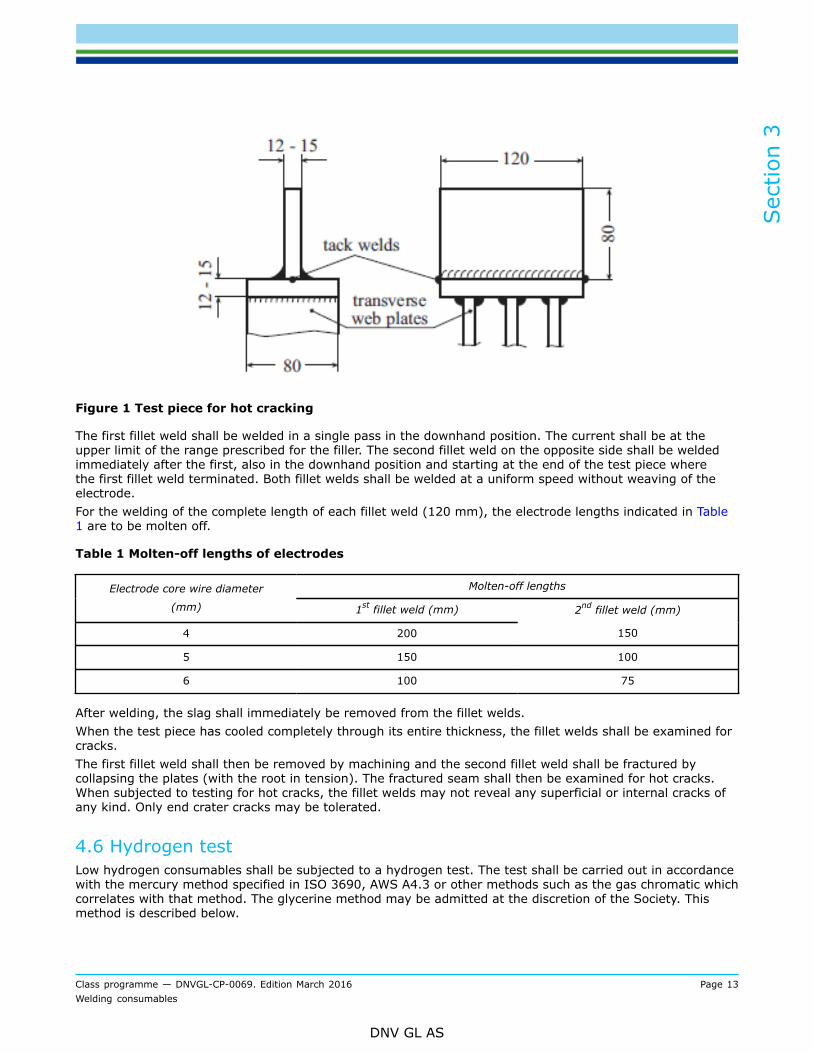
4.5 Hot crackingTwo plates shall for that purpose be welded together in the manner shown in Figure 1. The end face of theweb plate must be cut straight and at right angles and must fit snugly against the flat upper surface of thebottom plate. Any unevenness is to be removed. The base plate shall be stiffened by three transverse webplates.
Sec
tion
3
Class programme — DNVGL-CP-0069. Edition March 2016 Page 13Welding consumables
DNV GL AS
Figure 1 Test piece for hot cracking
The first fillet weld shall be welded in a single pass in the downhand position. The current shall be at theupper limit of the range prescribed for the filler. The second fillet weld on the opposite side shall be weldedimmediately after the first, also in the downhand position and starting at the end of the test piece wherethe first fillet weld terminated. Both fillet welds shall be welded at a uniform speed without weaving of theelectrode.For the welding of the complete length of each fillet weld (120 mm), the electrode lengths indicated in Table1 are to be molten off.
Table 1 Molten-off lengths of electrodes
Molten-off lengthsElectrode core wire diameter
(mm) 1st fillet weld (mm) 2nd fillet weld (mm)
4 200 150
5 150 100
6 100 75
After welding, the slag shall immediately be removed from the fillet welds.When the test piece has cooled completely through its entire thickness, the fillet welds shall be examined forcracks.The first fillet weld shall then be removed by machining and the second fillet weld shall be fractured bycollapsing the plates (with the root in tension). The fractured seam shall then be examined for hot cracks.When subjected to testing for hot cracks, the fillet welds may not reveal any superficial or internal cracks ofany kind. Only end crater cracks may be tolerated.
4.6 Hydrogen testLow hydrogen consumables shall be subjected to a hydrogen test. The test shall be carried out in accordancewith the mercury method specified in ISO 3690, AWS A4.3 or other methods such as the gas chromatic whichcorrelates with that method. The glycerine method may be admitted at the discretion of the Society. Thismethod is described below.
Sec
tion
3
Class programme — DNVGL-CP-0069. Edition March 2016 Page 14Welding consumables
DNV GL AS
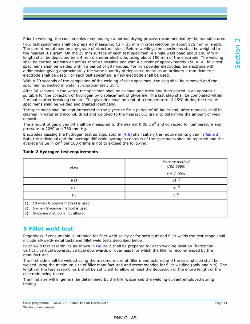
Prior to welding, the consumables may undergo a normal drying process recommended by the manufacturer.Four test specimens shall be prepared measuring 12 × 25 mm in cross-section by about 125 mm in length.The parent metal may be any grade of structural steel. Before welding, the specimens shall be weighed tothe nearest 0.1 gram. On the 25 mm surface of each test specimen, a single weld bead about 100 mm inlength shall be deposited by a 4 mm diameter electrode, using about 150 mm of the electrode. The weldingshall be carried out with an arc as short as possible and with a current of approximately 150 A. All four testspecimens shall be welded within a period of 30 minutes. For iron powder electrodes, an electrode witha dimension giving approximately the same quantity of deposited metal as an ordinary 4 mm diameterelectrode shall be used. For each test specimen, a new electrode shall be used.Within 30 seconds of the completion of the welding of each specimen, the slag shall be removed and thespecimen quenched in water at approximately 20°C.After 30 seconds in the water, the specimen shall be cleaned and dried and then placed in an apparatussuitable for the collection of hydrogen by displacement of glycerine. The last step shall be completed within2 minutes after breaking the arc. The glycerine shall be kept at a temperature of 45°C during the test. Allspecimens shall be welded and treated identically.The specimens shall be kept immersed in the glycerine for a period of 48 hours and, after removal, shall becleaned in water and alcohol, dried and weighed to the nearest 0.1 gram to determine the amount of welddeposit.The amount of gas given off shall be measured to the nearest 0.05 cm3 and corrected for temperature andpressure to 20°C and 760 mm Hg.Electrodes passing the hydrogen test as stipulated in [4.6] shall satisfy the requirements given in Table 2.Both the individual and the average diffusible hydrogen contents of the specimens shall be reported and theaverage value in cm3 per 100 grams is not to exceed the following:
Table 2 Hydrogen test requirements
Mark
Mercury method(ISO 3690)
cm3 / 100g
H15 15 1)
H10 10 2)
H5 5 3)
1) 10 when Glycerine method is used2) 5 when Glycerine method is used3) Glycerine method is not allowed
5 Fillet weld testRegardless if consumable is intended for fillet weld solely or for both butt and fillet welds the test scope shallinclude all-weld-metal tests and fillet weld tests described below.Fillet weld test assemblies as shown in Figure 2 shall be prepared for each welding position (horizontal-vertical, vertical upwards, vertical downwards or overhead) for which the filler is recommended by themanufacturer.The first side shall be welded using the maximum size of filler manufactured and the second side shall bewelded using the minimum size of filler manufactured and recommended for fillet welding (only one run). Thelength of the test assemblies L shall be sufficient to allow at least the deposition of the entire length of theelectrode being tested.The fillet size will in general be determined by the filler‘s size and the welding current employed duringtesting.

Sec
tion
3
Class programme — DNVGL-CP-0069. Edition March 2016 Page 15Welding consumables
DNV GL AS
Each test assembly shall be sectioned to form three macro-sections, each about 25 mm thick, as shown inFigure 3.
Figure 2 Fillet weld test assembly
Hardness readings shall be made in each section as indicated in Figure 3. The hardness of the weld shall bedetermined and shall meet the requirements in Table 3The hardness of both heat affected zone (HAZ) and base metal shall be determined and reported (forinformation).
Table 3 Weld hardness requirements
MethodGrades1, 2, 3
Grades2 Y, 3 Y, 4 Y, 5 Y
Grades2 Y40, 3 Y40,
4 Y40
Vickers(50 or 100 N load)
To be reportedfor information min. 150 min. 160
Figure 3 Hardness readings
Breaking test:One of the remaining sections of the fillet weld shall have the weld on the first side gouged or machinedto facilitate breaking the fillet weld on the second side by closing the two plates together, subjecting theroot of the weld to tension. On the other remaining section, the weld on the second side shall be gouged or

Sec
tion
3
Class programme — DNVGL-CP-0069. Edition March 2016 Page 16Welding consumables
DNV GL AS
machined and the section fractured using the same procedure. The fractured surfaces shall be examined andthere shall be no evidence of incomplete penetration or internal cracking and they shall be reasonably freefrom porosities.
6 Welding consumables for corrosion resistant steel for oil cargotanksRequirements are supplementary and apply to welding consumables intended for welding of corrosionresistant steels for cargo oil tanks.Approval will be considered subject to compliance with requirements of MSC.289(87) for corrosion testingand relevant requirements as specified in [4]. (covered electrodes), [5]. (wire/flux combinations) or [7].(wire/gas combinations). The corrosion testing shall be performed for butt weld test assembly. The basemetal to be used shall be the same as that for which the welding consumable is intended.Test plan shall be submitted for a review and verification prior start of approval process.The class may require other tests to be performed or stipulate other values for the required properties if theyare more appropriate to the character of the welding consumables or are necessitated by the intended use ofthe material.The approved welding consumable will be granted corresponding designation RCU, RCB or RCW to the grade,e.g. IV Y40(H5) RCU.Approval may be given for application in one or more of the following areas of a cargo oil tank:
a) lower surface of strength deck and surrounding structures (RCU)b) upper surface of inner bottom plating and surrounding structures (RCB)c) for both strength deck and inner bottom plating (RCW).
7 Welding consumables with qualified CTOD propertiesRequirements are supplementary and apply to welding consumables intended for the steel grades withspecified CTOD properties, eg grades with the suffix COD. Test of the weld metal shall be carried out inaccordance with RU SHIP Pt.2 Ch.1 Sec.3 and comply the acceptance criteria given in RU SHIP Pt.2 Ch.4Sec.5 [5.7] and RU SHIP Pt.2 Ch.4 Sec.5 [8].The base metal to be used shall be of the same strength and impact toughness grade and with similarchemical composition as that for which the welding consumable is intended. Two test assemblies shall beprepared in lowest and highest heat input and using plate of the greatest thickness for which approval isrequested.Approval will be granted for actual material grade, heat input and thickness ranges as per RU SHIP Pt.2 Ch.1Sec.3.The approved welding consumable will be granted designation COD to the grade, e.g. IV Y40MS(H5)COD.
8 Re-testingTensile and bend test:Where the result of a tensile or bend test does not comply with the requirements, double quantity ofspecimens of the same type shall be tested and all new test results shall meet the requirements. Whereinsufficient original welded assembly is available, a new assembly shall be prepared using weldingconsumables from the same batch and with the same procedure as the original assembly. In this case onlythe failed test specimens’ needs to be prepared and tested. Otherwise, all test specimens should be preparedas for re-testing.
Charpy V-notch impact testWhen the average value of a set of three impact test specimens fails to meet the stated requirements, orthe value of more than one specimen is below the required average value, or when the value of only onespecimen is below 70% of the specified average value, three additional specimens from the same piece may

Sec
tion
3
Class programme — DNVGL-CP-0069. Edition March 2016 Page 17Welding consumables
DNV GL AS
be tested and the results added to those previously obtained to form a new average. If this new averagecomplies with the requirements and if no more than two individual results are lower than the requiredaverage and no more than one of these two is below 70% of the specified average value, the tests may beaccepted.
Sec
tion
4
Class programme — DNVGL-CP-0069. Edition March 2016 Page 18Welding consumables
DNV GL AS
SECTION 4 COVERED ELECTRODES FOR SHIELDED METAL ARCWELDING OF NORMAL AND HIGH STRENGTH STEELS
1 GeneralElectrodes will be divided into the following grades:
— for normal strength steels: 1, 2 and 3— for high strength steels with minimum yield strength up to 355 N/mm2: 2 Y, 3 Y, 4 Y and 5 Y— for high strength steels with minimum yield strength up to 390 N/mm2: 2 Y40, 3 Y40, 4 Y40 and 5 Y40.
Approval will be considered subject to compliance with the specified tests and requirements.Electrodes complying with the requirements stipulated in Sec.3 [4.6] will be given the suffix H15, H10 or H5added to the grade mark. Electrodes for high strength steels shall be hydrogen tested and shall satisfy therequirements for at least the suffix H15. Hydrogen test for the largest diameter should be performed.
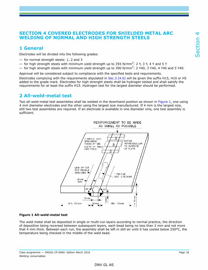
2 All-weld-metal testTwo all-weld-metal test assemblies shall be welded in the downhand position as shown in Figure 1, one using4 mm diameter electrodes and the other using the largest size manufactured. If 4 mm is the largest size,still two test assemblies are required. If an electrode is available in one diameter only, one test assembly issufficient.
Figure 1 All-weld-metal test
The weld metal shall be deposited in single or multi-run layers according to normal practice, the directionof deposition being reversed between subsequent layers, each bead being no less than 2 mm and not morethat 4 mm thick. Between each run, the assembly shall be left in still air until it has cooled below 250°C, thetemperature being checked in the middle of the weld bead.

Sec
tion
4
Class programme — DNVGL-CP-0069. Edition March 2016 Page 19Welding consumables
DNV GL AS
Test specimens:One longitudinal tensile and three impact test specimens shall be taken from each test assembly as shown inFigure 1.The test specimens shall be prepared according to Sec.3 [4].
Test requirements:The test results shall comply with the requirements given in Table 1.Chemical analysis:The chemical analysis of the deposited weld metal in each test assembly shall be supplied by themanufacturer and shall include the content of all significant alloying elements.
Table 1 All-weld-metal test requirements
Tensile test Impact test
Grade Rm
(N/mm2)R eH
min. (N/mm 2)A5
min. (%)Z
(%)Temperature
(°C)KV, (J)
min. average
1
2
3
400 - 560 305
20
0
- 20
2 Y
3 Y
4 Y
5 Y
490 - 660 375
0
- 20
- 40
- 60
2 Y40
3 Y40
4 Y40
5 Y40
510 - 690 400
22 1)
0
- 20
- 40
- 60
47
1) Reduction of area to be reported for information.
3 Butt-weld testButt-weld test assemblies as shown in Figure 2 shall be prepared for each welding position (downhand,horizontal-vertical, vertical and overhead) for which the electrode is recommended, except that electrodessatisfying the requirements for downhand and vertical position will be considered as also complying with therequirements for the horizontal-vertical position.When an electrode is intended for downhand position only, one additional test assembly shall be prepared inthis position.
Welding procedure for test assemblies:Butt-welds in accordance with Figure 2 shall be welded in the positions and with the electrode diameters asspecified in Table 2.

Sec
tion
4
Class programme — DNVGL-CP-0069. Edition March 2016 Page 20Welding consumables
DNV GL AS
Table 2 Butt weld test pieces, welding positions and electrode diameters
Butt-weld test pieces required ...
... in position(s) ... with electrode diameter(s)
Position(s) appliedfor approval
No. Position Root pass Fill andcover passes
Back pass
4
3
3
5 to 82
4 or 5
4 or 5
4
4
4
All positions incl.vertical-down
(1) 3
1
1
1
1
PA (1G)
PF (3G)
PE (4G)
PG (3G) acc. to manufacturer's instructions
All positionsexcept
vertical-down(2) 3
1
1
1
PA (1G)
PF (3G)
PE (4G)
4
3
3
5 to 82
4 or 5
4 or 5
4
4
4
Downhandpositions andvertical-up
(3) 3
1
1
PA (1G)
PF (3G)
4
3
5 to 82
4 or 5
4
4
Downhandpositions only
(4 )
1
1
PA (1G)
PA (1G)
4
4
5 to 82
5 to 844
4
Horizontal-vertical PC (h-v) position only
1 PC (2G) 4 or 5 5 4
Other individualpositions
(x)
1 (x) as specified above
1) Electrode diameters (mm)2) filler passes with 5 or 6 mm size; last two runs including the cover pass with the largest diameter electrodes
produced, up to a maximum of 8 mm3) includes the horizontal-vertical PC (2G) position4) second pass with 5 or 6 mm size; all other filler and cover passes to be made with the largest diameter electrodes
produced, up to a maximum of 8 mm
Test specimens:One transverse tensile, two bend tests (face and root bend) and three impact test specimens shall be takenfrom each test assembly as shown in Figure 2.The test specimens shall be prepared according to Sec.3 [4].Test requirements:The test results shall comply with the requirements given in Table 3. The position of fracture in the transversetensile test specimen shall be reported. The bend test specimens will be considered as complying with therequirements if, after bending, no crack or defect having any dimensions exceeding 3 mm are seen on theouter surface of the test specimen.

Sec
tion
4
Class programme — DNVGL-CP-0069. Edition March 2016 Page 21Welding consumables
DNV GL AS
Figure 2 Butt weld test assembly
Table 3 Butt-weld test requirements
Tensile test Impact test, KV (J), minimum average
Grade Rm
min. (N/mm2)Temperature (°C)
Downhand,horizontal-vertical
and overhead
Vertical (upwardand downward)
1
2
3
400
20
0
- 20
2 Y
3 Y
4 Y
5 Y
490
0
- 20
- 40
- 60
47 34
Sec
tion
4
Class programme — DNVGL-CP-0069. Edition March 2016 Page 22Welding consumables
DNV GL AS
Tensile test Impact test, KV (J), minimum average
Grade Rm
min. (N/mm2)Temperature (°C)
Downhand,horizontal-vertical
and overhead
Vertical (upwardand downward)
2 Y40
3 Y40
4 Y40
5 Y40
510
0
- 20
- 40
- 60
39
4 Covered electrodes for gravity or contact weldingWhere an electrode is submitted solely for approval for use in contact welding using automatic gravity orsimilar welding devices, deposited metal tests, fillet weld tests (see Sec.3 [5]) and, where appropriate, buttweld tests similar to those for normal manual electrodes shall be carried out using the process for which theelectrode is recommended by the manufacturer.Where an electrode is submitted for approval for use in contact welding using automatic gravity or similarwelding devices in addition to normal manual welding, fillet weld and, where appropriate, butt weld tests,using the gravity or other contact device as recommended by the manufacturer, shall be carried out inaddition to the normal approval tests.Preparation of test assembly:The fillet welding shall be carried out using the welding process recommended by the manufacturer, withthe longest size of the electrode manufactured. The manufacturer’s recommended current range shall bereported for each electrode size.
5 Deep penetration electrodesDeep penetration electrodes will be approved as grade 1 electrode only. The suffix DP will be added.If an electrode approved as a normal penetration electrode is also desired approved as a deep penetrationelectrode for downhand butt welding and horizontal-vertical fillet welding, the additional tests given belowshall be carried out.The electrode will be tested as a normal penetration electrode and the full series of tests shall be carried out,together with the deep penetration tests given below.
5.1 Butt weld testButt weld test assemblies in the downhand position:Two plates of thickness equal to twice the diameter of the core of the electrode plus 2 mm shall be buttwelded, with one downhand run of welding from each side, see Figure 3.The joint edges shall be prepared square and smooth. The gap is not to exceed 0.25 mm after the tackwelding.The test assembly shall be welded with an 8 mm diameter electrode or the largest size manufactured if thisis less than 8 mm.Test specimens: Two transverse tensile, two bend (one face and one root bend) and three impact testspecimens shall be taken as shown in Figure 3.The test specimens shall be prepared according to [4].

Sec
tion
4
Class programme — DNVGL-CP-0069. Edition March 2016 Page 23Welding consumables
DNV GL AS
Figure 3 Deep penetration butt weld tests
Test requirements:The transverse tensile strength shall not be less than 400 N/mm2.The bend test specimens can be considered as complying with the requirements if, after bending, no crack ordefect having any dimensions exceeding 3 mm can be seen on the outer surface of the test specimen.The average impact value for the three specimens taken from the centre of the weld shall not be less than 47J at +20°C.
5.2 Fillet weld testA fillet weld test assembly shall be prepared as shown in Figure 4. The welding shall be carried out in one runfor each fillet weld, with plate A in the horizontal plane during welding. The length of the fillet weld shall be160 mm and the gap between the plates is not to exceed 0.25 mm.One side shall be welded with 4 mm diameter electrode and the second side shall be welded with themaximum size of electrode manufactured. The welding current used shall be within the range recommendedby the manufacturer and the welding shall be carried out using normal welding practice.The welded assembly shall be cut by sawing or machining about 35 mm from the ends of the fillet welds andthe joints shall be ground, polished and etched.
Fillet weld test requirements:The welding of the fillet made with a 4 mm diameter electrode shall show a penetration of 4 mm, see Figure4, and the corresponding penetration of the fillet made with the maximum size electrode shall be reported.

Sec
tion
4
Class programme — DNVGL-CP-0069. Edition March 2016 Page 24Welding consumables
DNV GL AS
Figure 4 Deep penetration fillet weld test
6 Annual test
6.1 Covered electrodes for normal welding:Two all-weld metal test assemblies shall be prepared in accordance with [2]. The extents of testing andmechanical requirements shall be as given in [2].These requirements also apply to electrodes which are approved for fillet welding only.For covered electrodes with Mark H10 and Mark H5 one hydrogen test is required.
6.2 Covered electrodes for gravity or contact weldingOne all-weld metal test assembly using the gravity or other contact device as recommended by themanufacturer shall be prepared. If this electrode is approved also for normal manual arc welding, the annualtest shall be performed according to [6.1].
6.3 Covered electrodes for deep penetrationOne butt weld test assembly shall be prepared as given in [5].One transverse tensile test specimen, two bend (one face and one root) test and three impact test specimensshall be prepared. At each cut in the test assembly, the joints shall be examined to ensure that completefusion has taken place.For those electrodes which are approved for both normal penetration welding and for deep penetrationwelding in the downhand position, deep penetration weld tests shall be carried out in addition to the all-weldmetal tests for normal penetration.Annual test requirements:The tensile strength, yield stress, elongation and impact test results are all to comply with the requirementsfor initial approval tests.Additional tests:If any of the above tests fails, re-testing shall be carried out in accordance with Sec.3 [9].
7 Upgrading and upratingNormal requirements for annual testing shall be fulfilled in addition to the tests specified below:For upgrading of notch toughness, impact testing shall be carried out from the butt weld test assemblieswelded in each respective position. Testing to be performed a the upgraded temperature.If uprating is requested in order to cover the welding of higher strength steels all butt weld tests shall beperformed again. A material of higher strength shall be used as parent plate.

Sec
tion
4
Class programme — DNVGL-CP-0069. Edition March 2016 Page 25Welding consumables
DNV GL AS
Welding consumables which have not previously been subjected to a hydrogen test, shall be tested accordingto Sec.3 [4.5] when uprating to the grades 2, 3, 4, 5 Y H15/H10/H5 and 2, 3, 4, 5 Y40 H15/H10/H5.

Sec
tion
5
Class programme — DNVGL-CP-0069. Edition March 2016 Page 26Welding consumables
DNV GL AS
SECTION 5 WIRE/FLUX COMBINATIONS FOR SUBMERGED ARCWELDING
1 GeneralWire/flux combinations will be divided into the following grades:
— for normal strength steels: I, II and III— for high strength steels with minimum yield strength up to 355 N/mm2: I Y, II Y, III Y, IV Y and V Y— for high strength steels with minimum yield strength up to 390 N/mm2: II Y40, III Y40, IV Y40 and V Y40.
Approval will be considered subject to compliance with the specified tests and requirements in [2] and [3].The tests are intended for automatic single or multiple electrode submerged arc welding and thecombinations are divided into the following categories:
— for use with the multi-run technique— for use with the two-run technique.
The suffixes T, M or TM will be added to the grade mark to indicate two-run technique, multi-run technique orboth techniques, respectively.When a manufacturer states that a particular wire/flux combination is suitable for welding with bothtechniques, both series of tests shall be carried out.
2 Multi-run techniqueWhere approval for use with multi-run technique is requested, all-weld-metal and butt-weld tests shall becarried out as specified in [2.1] and [2.2].
2.1 All-weld-metal test:One all-weld-metal test assembly shall be welded in the downhand position as shown in Figure 1.The direction of deposition of each run shall alternate from each end of the plate. After completion of eachrun, the flux and welding slag shall be removed. Between each run, the assembly shall be left in still air untilit has cooled to 250°C, the temperature taken in the centre of the weld on the surface of the seam. Thethickness of each layer ishall not be less than the diameter of the wire, nor less than 4 mm.Test specimens:Two longitudinal tensile and three impact test specimens shall be taken from the test assembly as shown inFigure 1.The test specimens shall be prepared according to Sec.3 [4].Test requirements:The test results shall comply with the requirements given in Table 1.

Sec
tion
5
Class programme — DNVGL-CP-0069. Edition March 2016 Page 27Welding consumables
DNV GL AS
Figure 1 Multi-run weld. All-weld-metal test
Table 1 Submerged arc welding, all-weld-metal test requirements
Tensile test Impact test
Grade Rm
(N/mm2)ReH
min. (N/mm2)A5
min. (%)Z
(%)Temperature
(°C)
KV (J)minimumaverage
III
III400 - 560 305
200
- 20
I YII Y
III Y
IV Y
V Y
490 - 660 375
22 1) 200
- 20
- 40
- 60
34

Sec
tion
5
Class programme — DNVGL-CP-0069. Edition March 2016 Page 28Welding consumables
DNV GL AS
Tensile test Impact test
Grade Rm
(N/mm2)ReH
min. (N/mm2)A5
min. (%)Z
(%)Temperature
(°C)
KV (J)minimumaverage
II Y40III Y40
IV Y40
V Y40
510 - 690 400
0- 20
- 40
- 60
39
1) Reduction of area to be reported for information
Chemical analysis:The chemical analysis of the deposited weld metal shall be supplied by the manufacturer and shall includethe content of all significant alloying elements.
2.2 Butt weld test:One butt weld test assembly shall be welded in the downhand position as shown in Figure 2.The welding shall be carried out by the multi-run technique and the welding conditions shall be the same asthose adopted for the all weld metal test assembly.The back sealing run shall be applied in the downhand position after cutting out the root run to clean metal.Test specimens:Two transverse tensile, four bend (two face and two root bend) and three impact test specimens shall betaken from the test assembly as shown in Figure 2.The test specimens shall be prepared according to Sec.3 [4].

Sec
tion
5
Class programme — DNVGL-CP-0069. Edition March 2016 Page 29Welding consumables
DNV GL AS
Figure 2 Multi-run weld. Butt weld test
Table 2 Submerged arc welding, butt-weld-test requirements
Tensile test Impact test
Grade Rm
min. (N/mm2)Temperature (°C)
KV (J)Minimum average
III
III400
200
- 20
I YII Y
III Y
IV Y
V Y
490
200
- 20
- 40
- 60
34

Sec
tion
5
Class programme — DNVGL-CP-0069. Edition March 2016 Page 30Welding consumables
DNV GL AS
Tensile test Impact test
Grade Rm
min. (N/mm2)Temperature (°C)
KV (J)Minimum average
II Y40III Y40
IV Y40
V Y40
510
0- 20
- 40
- 60
39
Test requirements:The test results shall all comply with the requirements given in Table 2. The position of fracture in thetransverse tensile test shall be reported. The bend test specimens can be considered as complying with therequirements if, after bending, no crack or defect having any dimensions exceeding 3 mm can be seen on theouter surface of the test specimen.
3 Two-run techniqueWhere approval for use with two-run technique is requested, two butt weld test assemblies shall be prepared.When a wire/flux combination is submitted for approval for use with the two-run technique only, no allweldmetal test assembly is required. In this case approval tests are limited to the butt weld tests describedhereafter.Two butt-weld test assemblies shall be prepared, using the following thicknesses:
for grades I and IY 12-15 mm and 20-25 mm
for grades II to VY 20-25 mm and 30-35 mm.
for grades II Y40 to V Y40 20-25 mm and 30-35 mm.
The maximum diameter of wire, grades of steel plate and edge preparation to be used shall be in accordancewith that shown in Figure 4. Minor deviations from the stipulated edge preparation may be accepted, ifrequested by the manufacturer. The root gap is not to exceed 1 mm. Each butt weld shall be welded in tworuns, one from each side, using amperage, voltage and travel speed in accordance with the recommendationsof the manufacturer and normal good welding practice. After completion of the first run, the flux and weldingslag shall be removed and the assembly shall be left in still air until it has cooled to 100°C, the temperaturetaken in the centre of the weld, on the surface of the seam.Test specimens:Two transverse tensile, two bend (one from each side welded) and three impact test specimens shall betaken from each test assembly as shown in Figure 3.When approval is required for two-run technique only, one longitudinal tensile test specimen is also to bemachined from the thicker plate tested as shown in Figure 3.This tensile test specimen shall be cut with the longitudinal axis coinciding with the centre of the weld about7 mm below the plate surface on the side from which the second run is made.The impact test specimens shall be machined from each welded assembly from the positions and with theorientations shown in Figure 5. The test specimens shall be prepared according to Sec.3 [4].Test requirements:The test results are all to comply with the requirements given in Table 1 for the longitudinal tensile testspecimens and Table 2 for the transverse tensile and impact test specimens. The bend test specimens can beconsidered as complying with the requirements if, after bending, no crack or defect having any dimensionsexceeding 3 mm can be seen on the outer surface of the test specimen.

Sec
tion
5
Class programme — DNVGL-CP-0069. Edition March 2016 Page 31Welding consumables
DNV GL AS
Figure 3 Two-run weld. Butt weld test
4 Annual testsMulti-run technique:One all-weld-metal test — one tensile and three impact tests.Two-run technique:One butt-weld test, plate thickness 20 mm minimum — one transverse tensile, two bend and three impacttests. One longitudinal tensile test is also to be prepared for wire/flux combinations approved solely for thetwo-run technique.The preparation of the test assemblies and the mechanical requirements shall be in accordance with therequirements for the initial approval tests.
5 Upgrading and upratingl requirements for annual testing shall be fulfilled in addition to the tests specified below:For upgrading of notch toughness, impact testing to be carried out from the butt weld test assemblies weldedin each respective position. Testing to be performed a the upgraded temperature. For two-run technique abutt weld of maximum thickness approved shall be welded and tested.If uprating is requested in order to cover the welding of higher strength steels all butt weld tests shall beperformed again. Material of higher strength to be used for a parent plate, see Sec.4 [7] .

Sec
tion
5
Class programme — DNVGL-CP-0069. Edition March 2016 Page 32Welding consumables
DNV GL AS
Figure 4 Two-run weld, butt weld test, root gap 0 - 0.7 mm.
Figure 5 Two-run weld. Impact tests

Sec
tion
6
Class programme — DNVGL-CP-0069. Edition March 2016 Page 33Welding consumables
DNV GL AS
SECTION 6 COMBINATIONS FOR USE IN ONE-SIDE AUTOMATICWELDING PROCESSES
1 GeneralThis welding process will be divided into the following grades:
— for normal strength steels: I, II and III— for high strength steels with minimum yield strength up to 355 N/mm2: I Y, II Y, III Y, IV Y and V Y— for high strength steels with minimum yield strength up to 390 N/mm2: II Y40, III Y40, IV Y40 and V
Y40.
Approval will be considered subject to compliance with the specified tests and requirements in [2] and [3].Separate tests are specified for:
— one-run welding— multi-run welding .
Information regarding joint design, wire diameter, number of runs, tandem or multi-arc welding etc. shall bereported.The welding conditions shall be the same as those indicated for wire/flux combinations in [5], with theamendments and additions made in [2] to [7].
2 One-run weldingTwo test assemblies with 12-15 mm plate thickness shall be made. If a shipyard intends to apply the testedcombination for one-side, one-run welding on thicker plates, special procedure tests shall be carried out onthe thickest plate intended welded with this technique.Test specimens:The number of test specimens shall be as stipulated in [5] and as shown in Figure 1.Test requirements:The test results are all to comply with the requirements given in Table 1.
3 Multi-run weldingTwo test assemblies, one assembly with 15 - 25 mm plate thickness and one with 35 mm thickness, shall bemade as shown in Figure 1.Test specimens:The number of test specimens shall be as stipulated in [5] and as shown in Figure 1.Test requirements:The test results are all to comply with the requirements given in Table 1.
Sec
tion
6
Class programme — DNVGL-CP-0069. Edition March 2016 Page 34Welding consumables
DNV GL AS
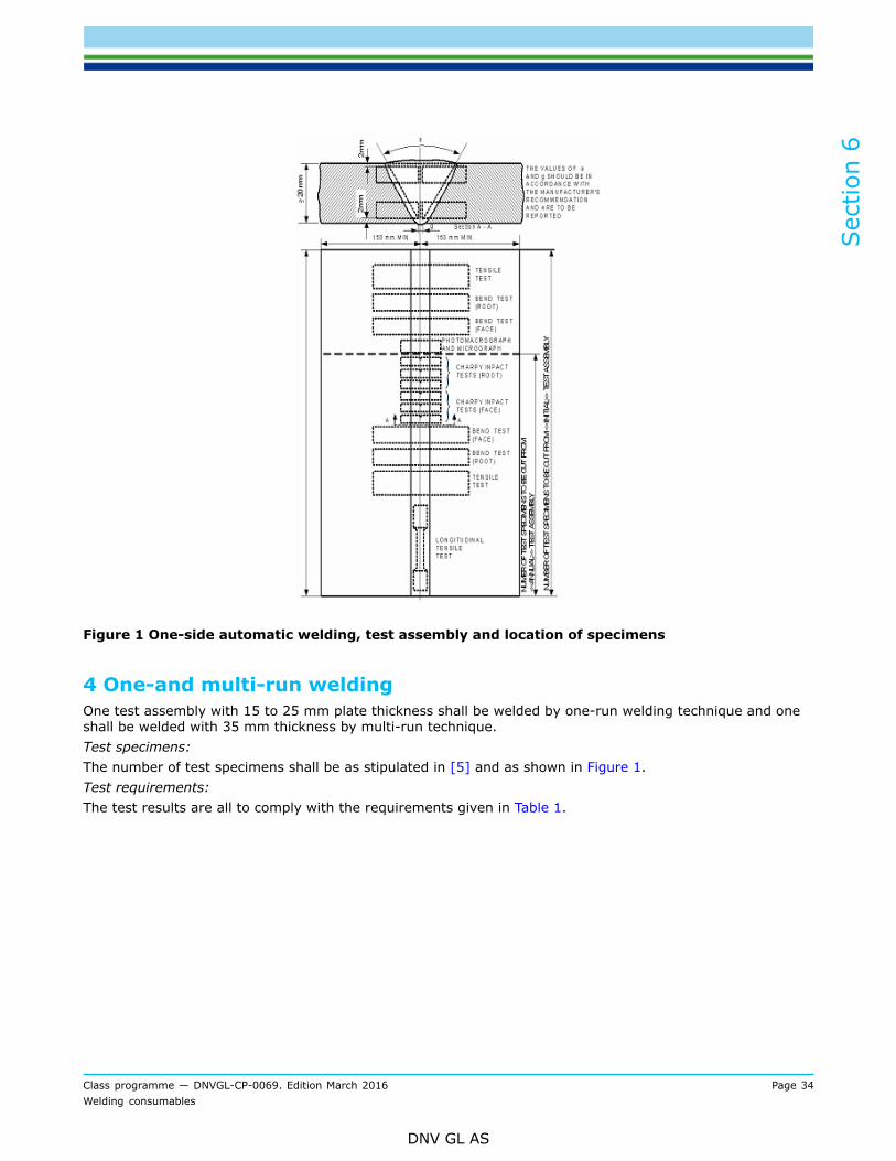
Figure 1 One-side automatic welding, test assembly and location of specimens
4 One-and multi-run weldingOne test assembly with 15 to 25 mm plate thickness shall be welded by one-run welding technique and oneshall be welded with 35 mm thickness by multi-run technique.Test specimens:The number of test specimens shall be as stipulated in [5] and as shown in Figure 1.Test requirements:The test results are all to comply with the requirements given in Table 1.

Sec
tion
6
Class programme — DNVGL-CP-0069. Edition March 2016 Page 35Welding consumables
DNV GL AS
5 Testing requirementsTest specimens:One longitudinal tensile, two transverse tensile, four transverse bend test (two face and two root bend) andsix impact (three from the face side and three from the root side) test specimens shall be taken from eachwelded test assembly as shown in Figure 1.The test specimens shall be prepared according to Sec.3 [4].Macro- and microstructure:One photomicrograph from the fusion zone of the thickest test assembly (one- or multi-run) shall also beforwarded for consideration.Chemical analysis:The chemical analysis of the deposited weld metal shall be supplied by the manufacturer and shall include allsignificant alloying elements.The test results shall all comply with the requirements given in Table 1. The position of fracture in thetransverse tensile test specimens shall be reported. The bend test specimens can be considered as complyingwith the requirements if, after bending, no crack or defect having any dimensions exceeding 3 mm can beseen on the outer surface of the test specimen.
Table 1 One - and multi run welding test requirements
Tensile test Impact test
LongitudinalGrade Transverse
(N/mm2) Rm
min. (N/mm2)ReH
min. (N/mm2)A5
min. (%)
Temperature(°C)
KV (J)minimumaverage
400 400 - 560 305200
- 20
I YII Y
III Y
IV Y
V Y
490 490 - 660 375
200
- 20
- 40
- 60
34
II Y40III Y40
IV Y40
V Y40
510 510 - 690 400
22
0- 20
- 40
- 60
39

Sec
tion
6
Class programme — DNVGL-CP-0069. Edition March 2016 Page 36Welding consumables
DNV GL AS
6 Annual testsCombinations approved for one- or multi-run welding shall be tested as follows:One test assembly with 12-25 mm plate thickness as shown in Figure 1 shall be welded.When a combination is approved for both one- and multi-run welding, the test assembly shall be welded withthe one-run technique.One longitudinal and one transverse tensile test specimen, two bend (one face and one root bend) and siximpact test specimens (three root and three face) shall be taken from the test assembly as shown in Figure1.The preparation of the test assemblies and the mechanical requirements shall be in accordance with therequirements for the initial approval tests.
7 Upgrading and upratingNormal requirements for annual testing shall be fulfilled in addition to the tests specified below:For upgrading of notch toughness, impact testing shall be carried out from the butt weld test assemblieswelded in each respective position. Testing shall be performed at the upgraded temperature.If uprating is requested in order to cover the welding of higher strength steels, all butt weld tests shall beperformed again. Material of higher strength to be used for a parent plate, see Sec.4 [7].

Sec
tion
7
Class programme — DNVGL-CP-0069. Edition March 2016 Page 37Welding consumables
DNV GL AS
SECTION 7 WIRES AND WIRE AND GAS COMBINATIONS FOR GASMETAL ARC WELDING
1 GeneralWire/gas combinations, flux cored or flux coated wires with or without shielding gas will be divided into thefollowing grades:
— for normal strength steels: I, II and III— for high strength steels with minimum yield strength up to 355 N/mm2: I Y, II Y, III Y, IV Y and V Y— for high strength steels with minimum yield strength up to 390 N/mm2: II Y40, III Y40, IV Y40 and V Y40.
Approval will be considered subject to compliance with the specified tests and requirements in [2] and [3].The wires are divided into the following categories:
— for use in semi-automatic multi-run welding— for use in automatic multi-run welding— for use in automatic two-run welding— for use with TIG welding.
For wires intended for automatic welding, the suffixes T, M and TM will be added to indicate two-run, multi-run or both welding techniques, respectively.For wires intended for semi-automatic welding, the suffix S will be added to the grade mark.For wires intended for both welding processes, the suffixes will be added in combination.For wires intended for TIG welding, the suffixes T, M and TM will be added to indicate two-run, multi-run orboth welding techniques, respectively.The test assemblies shall be prepared by the relevant welding technique for which approval is requested,however, where approval is requested for both semi-automatic and automatic techniques, test assembliesneed only be prepared by the semi-automatic technique. If approval of automatic two-run welding techniqueis requested, test assemblies are also to be prepared by this technique.Where applicable, the composition of the shielding gas shall be reported. Unless otherwise agreed by theSociety, additional approval tests are required when the shielding gas used is different from that used for theoriginal approval tests.Flux cored or flux coated wires may, at manufacturer's option, be submitted to a hydrogen test as detailed inSec.3 [4.5], using the manufacturer's recommended welding conditions and adjusting the deposition rate togive a weight of weld deposit per sample similar to that deposited when using manual electrodes.Wires complying with our requirements stipulated in Sec.3 [4.5] will have the suffix (H15), (H10) or (H5)added to the grade mark.
2 Semi-automatic multi-run weldingThe term semi-automatic is used to describe processes in which the weld is made manually by a welderholding a gun through which the wire is continuously fed.Where approval for use with semi-automatic welding is requested, all-weld-metal and butt-weld tests shall becarried out as specified in [2.1] and [2.2].
2.1 All-weld-metal test:Two all-weld-metal test assemblies shall be welded in the downhand position as shown in Sec.4 Figure 1.One test assembly shall be welded using a wire of 2.4 mm diameter or of the largest size manufactured andthe other using a wire of 1.2 mm diameter or of the smallest size manufactured. Where wires are available inone diameter only, one test assembly is sufficient.

Sec
tion
7
Class programme — DNVGL-CP-0069. Edition March 2016 Page 38Welding consumables
DNV GL AS
The weld metal shall be deposited according to the practice recommended by the manufacturer and thethickness of each layer of weld metal shall be in the range of 2 mm to 6 mm.Test specimens:One longitudinal tensile and three impact test specimens shall be taken from each test assembly as shown inSec.4 Figure 1.The test specimens shall be prepared according to Sec.3 [4].Test requirements:The test results are all to comply with the requirements given in Table 1.
Table 1 Semi automatic multi-run welding, all-weld-metal test requirements (Also for wiresintended for TIG welding)
Tensile test Impact test
Grade Rm
(N/mm2)ReH
min. (N/mm2)A5
min. (%)Z
(%)Temperature
(°C)
KV (J)minimum
average
III
III400 - 560 305
200
- 20
I YII Y
III Y
IV Y
V Y
490 - 660 375
200
- 20
- 40
- 60
II Y40III Y40
IV Y40
V Y40
510 - 690 400
22 1)
0- 20
- 40
- 60
47
1) Reduction of area to be reported for information
Chemical analysis:The chemical analysis of the deposited weld metal in each test assembly shall be supplied by themanufacturer and shall include the content of all significant alloying elements.
2.2 Butt-weld test:Butt-weld test assemblies as shown in Sec.4 Figure 2 shall be prepared for each welding position (downhand,horizontal-vertical, vertical and overhead) for which the wire is recommended. One test assembly shall beprepared in the downhand position, using a 1.2 mm diameter wire for the first run or a wire of the smallestsize manufactured and using a 2.4 mm diameter, or of the largest size manufactured for the remaining runs.In the case where the wire is intended for downhand position only, an additional test assembly shall beprepared by the same welding procedure using wires of different diameter.The other test assemblies shall be prepared in the vertical, horizontal-vertical and overhead positions usingfor the first run a wire of the smallest size manufactured and for the remaining runs the largest size of wirerecommended by the manufacturer for the position concerned.Test specimens:

Sec
tion
7
Class programme — DNVGL-CP-0069. Edition March 2016 Page 39Welding consumables
DNV GL AS
One transverse tensile, two bend (one face and one root bend) and three impact test specimens shall betaken from each test assembly as shown in Sec.4 Figure 2.The test specimens shall be prepared according to Sec.3 [4].Test requirements:The test results shall comply with the requirements given in Table 2. The position of fracture in the transversetensile test specimen shall be reported. The bend test specimens can be considered as complying with therequirements if, after bending, no crack or defect having any dimensions exceeding 3 mm can be seen on theouter surface of the test specimen.
2.3 Fillet weld testFillet weld test assemblies shall be made and tested in accordance with Sec.3 [6].
Table 2 Semi automatic multi-run welding - butt-weld test requirements (Also for wires intendedfor manually TIG welding)
Tensile test Impact test KV (J), minimum average
Grade Rm
min. (N/mm2)Temperature (°C) Downhand, horizontal-
vertical and overheadVertical (upwardand downward)
III
III400
200
- 20
I YII Y
III Y
IV Y
V Y
490
200
- 20
- 40
- 60
34
II Y40III Y40
IV Y40
V Y40
510
0- 20
- 40
- 60
47
39
3 Automatic multi-run weldingWhere approval for use with automatic multi-run welding is requested, all-weld-metal and butt-weld testsshall be carried out as specified in [3.1] and [3.2].
3.1 All-weld-metal test:One all-weld-metal test assembly shall be welded in the downhand position as shown in Sec.5 Figure 1.The preparation of the assembly shall be as described in Sec.5 [2], except that the thickness of each layer isnot to be less than 3 mm.Test specimens:Two longitudinal tensile and three impact test specimens shall be taken from the test assembly as shown inSec.5 Figure 1.The test specimens shall be prepared according to Sec.3 [4].Test requirements:

Sec
tion
7
Class programme — DNVGL-CP-0069. Edition March 2016 Page 40Welding consumables
DNV GL AS
The test results are all to comply with the requirements given in Table 3.
Table 3 Automatic multi-run welding all-weld-metal test requirements. (Also for wires intendedfor TIG welding)
Tensile test Impact test
Grade Rm,min. (N/mm2)
ReH
min.
(N/mm2)
A5
min. (%)Z
(%)Temperature
(°C)
KV (J)minimum
average
III
III400 - 560 305
200
- 20
I YII Y
IIIY
IV Y
V Y
490 - 660 375
200
- 20
- 40
- 60
34
II Y40III Y40
IV Y40
V Y40
510 - 690 400
22 1)
0- 20
- 40
- 60
39
1) Reduction of area to be reported for information
Chemical analysis:The chemical analysis of the deposited weld metal shall be supplied by the manufacturer and shall include allsignificant alloying elements.
3.2 Butt-weld test:One butt-weld test assembly shall be welded in the downhand position as shown in Sec.5 Figure 2.The test assembly shall be prepared in accordance with that prescribed in Sec.5 [2].Test specimens:Two transverse tensile, four bend (two face and two root bend) and three impact test specimens shall betaken from the test assembly as shown in Sec.5 Figure 2.The test specimens shall be prepared according to Sec.3 [4].Test requirements:The test results shall comply with the requirements given in Table 4. The position of fracture in the transversetensile test specimen shall be reported. The bend test specimens can be considered as complying with therequirements if, after bending, no crack or defect having any dimensions exceeding 3 mm can be seen on theouter surface of the test specimen.

Sec
tion
7
Class programme — DNVGL-CP-0069. Edition March 2016 Page 41Welding consumables
DNV GL AS
Table 4 Automatic multi-run welding - butt-weld test requirements. (Also for wires intended forTIG welding)
Tensile test Impact test
Grade Rm
min.
(N/mm2)Temperature (°C)
KV (J)minimum
average
III
III400
200
- 20
I YII Y
III Y
IV Y
V Y
490
200
- 20
- 40
- 60
34
II Y40III Y40
IV Y40
V Y40
510
0- 20
- 40
- 60
39
4 Two-run weldingWhen approval for use with two-run technique is requested, two butt-weld test assemblies shall be prepared.For wires to be approved for use with the two-run technique only, no all weld metal test is required. In thiscase approval tests are limited to the butt weld tests described hereafter.Two butt-weld test assemblies shall be prepared as specified in Sec.5 [3], except that one test assembly shallbe 12-15 mm thick and the other shall be 20 mm thick.If approval is required for welding of plates thicker than 20 mm, one assembly shall be prepared usinga plate of 20 mm in thickness and the other using a plate of the greatest thickness for which approval isrequired.The diameter of wire to be used for the test assemblies shall be in accordance with the manufacturer'srecommendation and shall be reported for information.The edge preparation of the test assemblies shall be as shown in Figure 1. Small deviations in the edgepreparation may be allowed, if requested by the manufacturer. For assemblies using plate over 20 mm inthickness, the edge preparation used shall be reported for information.

Sec
tion
7
Class programme — DNVGL-CP-0069. Edition March 2016 Page 42Welding consumables
DNV GL AS
Figure 1 Typical edge preparation of two-run technique for wires
Test specimens:Two transverse tensile, two bend (one from each side welded) and three impact test specimens shall betaken from each test assembly as shown in Sec.5 Figure 3.When approval is required for two-run technique only, one longitudinal tensile test specimen shall also bemachined from the thicker plate tested as shown in Sec.5 Figure 3.This tensile specimen shall be cut with the longitudinal axis coinciding with the centre of the weld about 7mm below the plate surface on the side from which the second run is made.The impact test specimens shall be machined from each welded assembly from the positions and with theorientations shown in Sec.5 Figure 5.The test specimens shall be prepared according to Sec.3 [4].Test requirements:The test results shall all comply with the requirements given in Table 3 for the longitudinal tensile testspecimens and Table 4 for the transverse tensile and impact test specimens. The bend test specimens can beconsidered as complying with the requirements if, after bending, no crack or defect having any dimensionsexceeding 3 mm can be seen on the outer surface of the test specimen.
5 Annual testSemi-automatic welding TIG welding and fillet welds:
— One all-weld-metal test - one longitudinal tensile and three impact tests.
Automatic multi-run welding only:
— One all-weld-metal test - one longitudinal tensile and three impact tests.
Automatic two-run welding only:
— One butt-weld test with 20 mm minimum plate thickness - one transverse tensile, two bend and threeimpact tests. One longitudinal tensile test shall also be prepared for wire/gas combinations approvedsolely for the two-run technique.
Wires approved for both semi-automatic and automatic multi-run welding:
— One all-weld-metal test in semi-automatic technique - one tensile and three impact tests.
The test assemblies and specimens shall be prepared and tested in accordance with the same procedures asthose for the initial approval tests using wire which is of about the medium size manufactured, except in thecase of the two-run technique where the size of wire shall be according to the initial testing procedure.The test results shall comply with the requirements for the initial approval tests.

Sec
tion
7
Class programme — DNVGL-CP-0069. Edition March 2016 Page 43Welding consumables
DNV GL AS
6 Upgrading and upratingNormal requirements for annual testing shall be fulfilled in addition to the tests specified below:For upgrading of notch toughness, impact testing shall be carried out from the butt weld test assemblieswelded in each respective position. Testing shall be performed at the upgraded temperature. For two-runtechnique a butt weld of maximum thickness approved shall be welded and tested.If uprating is requested in order to cover the welding of higher strength steels, all butt weld tests shall beperformed again. Material of higher strength to be used for a parent plate, see Sec.4 [7].
Sec
tion
8
Class programme — DNVGL-CP-0069. Edition March 2016 Page 44Welding consumables
DNV GL AS
SECTION 8 COMBINATIONS FOR USE IN ELECTRO-SLAG ANDELECTRO-GAS WELDING PROCESSES
1 GeneralConsumables intended for these welding processes will be divided into the following grades:
— for normal strength steels: I, II and III— for high strength steels with minimum yield strength up to 355 N/mm2: I Y, II Y, III Y, IV Y and V— for high strength steels with minimum yield strength up to 390 N/mm2: II Y40, III Y40, IV Y40 and V
Y40.
Approval will be considered subject to compliance with the specified tests and requirements in [2].
2 Initial testThe following information shall be reported for the Society's consideration:
— joint designation,— wire diameter,— type of consumable nozzle,— shielding gas if used,— welding parameters,— weld direction relative to final rolling direction of plates,— tensile strength and chemical composition including applied grain refining elements for the base material.
Two test assemblies, one assembly with 20 mm plate thickness and one with 35 mm thickness, shall bemade as shown in Figure 1.Test specimens:Two longitudinal and two transverse tensile test specimens, two macro-sections, two side bend (alternativelyone root bend and one face bend) and six impact (three with the notch located in the centre of the weld andthree with the notch located 2 mm from the fusion line in the deposited metal) test specimens shall be takenfrom each test assembly as shown in Figure 1.

Sec
tion
8
Class programme — DNVGL-CP-0069. Edition March 2016 Page 45Welding consumables
DNV GL AS
Figure 1 Electro-slag and electro-gas welding test assembly and location of specimens
Test requirements:The test results are all to comply with the requirements given in Table 1.

Sec
tion
8
Class programme — DNVGL-CP-0069. Edition March 2016 Page 46Welding consumables
DNV GL AS
Table 1 Electro-slag and electro-gas welding test requirements
Tensile test Impact test
Grade Rm
(N/mm2)
ReH
min.
(N/mm2)
A5
min. (%)Temperature
(°C)
KV (J)minimum
average
III
III400 - 560 305
200
- 20
I YII Y
III Y
IV Y
V Y
490 - 660 375
200
- 20
- 40
- 60
34
II Y40III Y40
IV Y40
V Y40
510 - 690 400
22
0- 20
- 40
- 60
39
Chemical analysis:Chemical analysis of the deposited weld metal shall be supplied by the manufacturer and shall include thecontent of all significant alloying elements.Photo macrographs:Two photo macrographs, approximately 2X magnification, one transverse and one longitudinal with respect tothe weld shall be taken. The latter section shall be parallel to the plate surface.
3 Annual testOne test assembly, using 20 mm plate thickness shall be prepared.Two longitudinal, two bend and two sets of three impact test specimens shall be taken. The notch of theimpact specimens shall be located in the centre of the weld and 2 mm from the fusion line in the depositedmetal.One transverse photo macrograph shall be taken from the test assembly.The preparation of the test assemblies and the mechanical properties shall be in accordance with therequirements for the initial approval tests.
4 Upgrading and upratingFor upgrading and uprating the full test scope from butt weld assemblies as specified in [2] is required.
Sec
tion
9
Class programme — DNVGL-CP-0069. Edition March 2016 Page 47Welding consumables
DNV GL AS
SECTION 9 WELDING CONSUMABLES FOR WELDING OF STEELGRADES VL 2-4, VL 2-4L, VL 4-4 AND VL 4-4L FOR LOW-TEMPERATURE
1 GeneralThese welding consumables will be granted the following grades:
— for VL 2-4 and VL 2-4L: 5 (manual welding) and V (semi-automatic and automatic welding)— for VL 4-4 and VL 4-4L: 5 Y (manual welding) and V Y (semi-automatic and automatic welding).
Approval will be considered subject to compliance with the specified tests and requirements in [2].Covered electrodes shall satisfy the requirements for low hydrogen electrodes, and will have the suffix H15,H10 or H5 added to the grade mark.Flux cored or flux coated wires may also, at manufacturer’s option, be submitted for hydrogen testing, andwill have the suffix (H15), (H10) or (H5) added to the grade mark.Testing shall be carried out as specified in [4]. (covered electrodes), 5. (wire/flux combinations) or [7]. (wire/gas combinations) with the additional requirements specified in [2].
2 Additional requirementsThe base metal to be used for the butt weld tests shall be the same as that for which the weldingconsumable is intended.Test requirements:The butt-weld test results are all to comply with the requirements given in Table 1.One additional butt-weld test shall be made in the downhand position. This test assembly shall be subjectedto stress-relieving at 550 to 600°C prior to mechanical testing.Test specimens:One transverse tensile and three impact test specimens shall be taken from each test assembly.The impact specimens shall be broken at -60°C. Both single values and average values shall be reported.Welding consumables intended for VL 2-4 and VL 4-4 only, may be impact tested at -55°C.Test requirements:The test results shall comply with the requirements given in Table 1.
3 Annual testDepending on whether it concerns electrodes, wire/flux combination or wire/gas combinations, the testingshall be carried out according to that prescribed in Sec4. [8], Sec.5 [2] or Sec.7 [5], respectively. Impacttesting, however, shall be carried out according to [2] i.e. on one additional butt-weld assembly shall bewelded.. Test assembly shall be subjected to stress-relieving prior to mechanical testing.
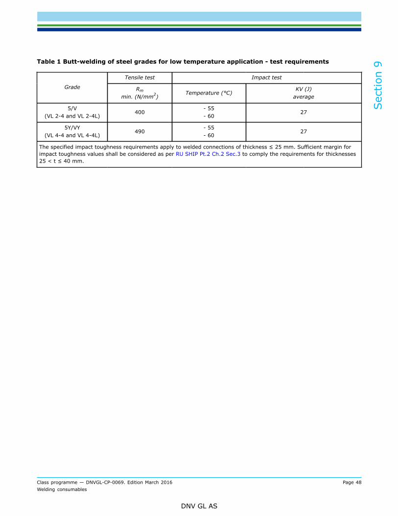
Sec
tion
9
Class programme — DNVGL-CP-0069. Edition March 2016 Page 48Welding consumables
DNV GL AS
Table 1 Butt-welding of steel grades for low temperature application - test requirements
Tensile test Impact test
Grade Rm
min. (N/mm2)Temperature (°C)
KV (J)average
5/V(VL 2-4 and VL 2-4L)
400- 55- 60
27
5Y/VY(VL 4-4 and VL 4-4L)
490- 55- 60
27
The specified impact toughness requirements apply to welded connections of thickness ≤ 25 mm. Sufficient margin forimpact toughness values shall be considered as per RU SHIP Pt.2 Ch.2 Sec.3 to comply the requirements for thicknesses25 < t ≤ 40 mm.

Sec
tion
10
Class programme — DNVGL-CP-0069. Edition March 2016 Page 49Welding consumables
DNV GL AS
SECTION 10 WELDING CONSUMABLES FOR LOW-ALLOY, HEAT-RESISTING STEELS (VL 0.3MO, VL 1CR 0.5MO AND VL 2.25CR 1MO)
1 GeneralThe all-weld-metal and butt-weld tests are all to be carried out as specified in 4. (covered electrodes), 5.(wire/flux combinations) or [7] (wire/gas combinations) with the additional requirements specified in [2] to[4].Covered electrodes shall satisfy our requirements for low hydrogen electrodes, and will have the suffix H15,H10 or H5 added to the grade mark.Flux cored or flux coated wires may also, at manufacturer's option, be submitted for hydrogen testing, andwill have the suffix (H15), (H10) or (H5) added to the grade mark. The base metal to be used for the butt-weld tests shall be the same as that for which the welding consumable is intended.Steel grades A, B or D may, however, be used for the all-weld-metal tests when this is found to beconvenient.
2 All weld metal testThe additional all-weld-metal test shall be performed. Two longitudinal tensile test specimens shall be takenfrom each test assembly as shown in Figure 1Pre- and post-heating:The temperature ranges to be used for pre-heating, inter-pas temperature and annealing is shown in Table 1.
Table 1 Low alloy heat utility steels - pre and post heat temperature ranges
Consumables forwelding steel grade
Pre-heat andinter-pass temperature
(°C)
AnnealingTemperature
(°C)
VL 0.3Mo 100 - 200 660 - 700
VL 1Cr 0.5Mo 200 - 300 680 - 720
VL 2.25Cr 1Mo 200 - 300 720 - 770
The finished test plates shall be uniformly heated to the annealing temperature, kept at this temperature forapproximately 30 minutes and cooled in still air.Tensile tests:One specimen from each assembly shall be tested at room temperature (approximately 20°C), while theother shall be tested at 400°C ± 5°C. The elevated test temperature shall be properly controlled (e.g. bythermocouples).Test requirements:The test results are all to comply with the requirements given in Table 2.

Sec
tion
10
Class programme — DNVGL-CP-0069. Edition March 2016 Page 50Welding consumables
DNV GL AS
Figure 1 All-weld-metal test
Table 2 All weld test temperature and tensile test requirements
Tensile test
Consumables forwelding steel grade
Test temperature(°C)
Rm
min.
(N/mm2)
ReH or Rp 0.2
min.
(N/mm2)
A5
min. (%)Z
(%)
VL 0.3Mo20400
440 1) 24
VL 1Cr 0.5Mo20400
470 1) 20
VL 2.25Cr 1Mo20400
480 1)
305
18
1)
1) These values shall be reported for information
3 Butt weld testThe transverse tensile and bend tests shall be tested at room temperature.Test requirements:The tensile test results shall comply with the requirements given in Table 3.
Table 3 Butt-weld tensile test requirements
Consumables for welding steel gradeRm
min. (N/mm2)
VL 0.3Mo 440

Sec
tion
10
Class programme — DNVGL-CP-0069. Edition March 2016 Page 51Welding consumables
DNV GL AS
Consumables for welding steel gradeRm
min. (N/mm2)
VL 1Cr 0.5Mo 470
VL 2.25Cr 1Mo 480
4 Chemical compositionThe test specimen for chemical analysis of the deposited metal shall be made on a steel plate as shown inFigure 2.Preparation of test assembly:One such test specimen shall be made for each dimension of welding consumable to be approved. Chips forchemical analysis shall be machined, so that the distance between the final cut and the plate corresponds toat least 4 layers of weld.
Figure 2 Test specimen for chemical analysis
Each test specimen shall be analysed separately.Test requirements:The test results shall comply with the requirements given in Table 4.
Table 4 Chemical analysis - test requirements
Consumablesfor welding
steel grade
CMax.
(%)
SiMax.
(%)
Mn
(%)
Cr
(%)
Mo
( )%
PMax.
(%)
SMax.
(%)
VL 0.3Mo 0.6 - 1.6 - 0.3 - 0.7
VL 1Cr 0.5Mo 0.4 - 1.0 0.7 - 1.4 0.4 - 0.7
VL 2.25Cr 1Mo
0.12 0.8
0.4 - 1.0 2.0 - 2.6 0.9 - 1.2
0.04 0.03
5 Annual test

Sec
tion
10
Class programme — DNVGL-CP-0069. Edition March 2016 Page 52Welding consumables
DNV GL AS
Chemical analyses of the deposited metal of two different dimensions of the approved combinations shall becarried out.The preparation of the test assemblies and the test requirements shall be in accordance with therequirements for the initial approval tests specified in [4].

Sec
tion
11
Class programme — DNVGL-CP-0069. Edition March 2016 Page 53Welding consumables
DNV GL AS
SECTION 11 WELDING CONSUMABLES FOR WELDING OF STEELGRADES VL 1.5NI; VL 3.5NI; VL 5NI AND VL 9NI
1 GeneralThe all-weld-metal and butt-weld tests shall be carried out as specified in [4] (covered electrodes), [5] (wire/flux combinations) or [7] (wire/gas combinations) with the additional requirements specified in [2].Covered electrodes shall satisfy the requirements for low hydrogen electrodes, and will have the suffix H15,H10 or H5 added to the grade mark.Flux cored or flux coated wires may also, at manufacturer's option, be hydrogen tested, and have the suffix(H15), (H10) or (H5) added to the grade mark.The plate thickness for the butt-weld tests shall normally be between 11 mm and 20 mm. If plates withthickness less than 11 mm are used, the requirement regarding absorbed energy shall be agreed upon withthe Society in each case.Welding consumables approved for welding of a higher grade within this group may also be used for thelower grades.
2 All-weld-metal test:Test specimens:One longitudinal tensile and at least three impact test specimens shall be machined from each test assembly.Test requirements:The longitudinal tensile and impact test results shall satisfy the requirements given in Table 1.
3 Butt-weld test:Test specimens:One transverse tensile, three impact test specimens and two transverse bend tests shall be taken from eachtest assembly.If the composition and mechanical properties of the deposited metal differ markedly from the compositionand properties of the base metal, the two transverse bend tests may be replaced by longitudinal bend tests.If this is done, one face bend and one root bend test shall be carried out.The dimensions of the longitudinal bend specimens shall be as follows:
— length minimum 150 mm— width 38 mm— thickness 10 mm.
The weld reinforcements shall be removed, and the root/face side of the specimens shall be machined so thatthe required thickness is obtained. The edges of the specimens may be rounded to a radius not exceeding 2mm.The obtained tensile strength shall not be below the specified minimum tensile strength for the base metal inquestion.Test requirements:The test results are all to comply with the requirements given in Table 1. The position of fracture in thetransverse tensile test specimen shall be reported. The bend test specimens can be considered as complyingwith the requirements if, after bending through an angle of 180° over a former with a diameter of 4xt mm,no cracks or defects can be seen on the outer surface of the test specimen. The reduction of area shall bereported for information.

Sec
tion
11
Class programme — DNVGL-CP-0069. Edition March 2016 Page 54Welding consumables
DNV GL AS
Table 1 Annual test requirements
Tensile test Impact test
All-weld-metal Butt weldConsumablesfor weldingsteel grade
Rm
min.
(N/mm2)
ReH 1)
min.
(N/mm2)
A5
min. (%)
Rm
min.
(N/mm2)
Temperature(°C)
KV (J)minimum
average
VL 1.5NiVL 3.5NiVL 5Ni
VL 9Ni
470540570640
355355390
49025
470540
570640
- 95- 115
- 140
- 196
27
1) In case of no marked yield point, the proof stress at 0.2% elongation (Rp0.2) shall be reported
4 Annual testDepending on whether it concerns electrodes, wire/flux combination of wire/gas combinations, the testingshall be carried out according to that prescribed in Sec.4 [6], Sec.5 [4] or Sec.7 [5], respectively. The testresults shall, however, comply with the requirements given in Table 1.
5 Other welding consumablesWelding consumables with yield stress and/or tensile strength less than that specified in Table 1, may beapproved for welding of steel grade VL 9 Ni. Approval testing shall be carried out according to the programmespecified above.The maximum permissible stress in welded vessels shall, however, in such cases be based on the mechanicalproperties obtained from the approval tests.

Sec
tion
12
Class programme — DNVGL-CP-0069. Edition March 2016 Page 55Welding consumables
DNV GL AS
SECTION 12 WELDING CONSUMABLES FOR WELDING OF EXTRAHIGH STRENGTH STEELS
1 GeneralDepending on the impact test temperature, welding consumables for extra high strength steels are dividedinto the following grades:
— Grade 3/III, test temperature - 20°C— Grade 4/IV, test temperature - 40°C— Grade 5/V, test temperature - 60°C.
The following symbols are added to the grade mark to indicate yield strength of the base metal for which thewelding consumable is intended:
Symbols added to grade mark Base material designation
Y42Y46
Y50
Y55
Y62
Y69
VL 420VL 460, VL 47
VL 500, VL 47
VL 550
VL 620
VL 690
Each higher quality grade includes the one (or those) below. Grade AEH and DEH steels according to RUSHIP Pt.2 Ch.2 Sec.2 shall be welded using welding consumables of at least quality grade 3/III, grade EEHsteels using at least quality grade 4/IV and grade FEH steels using at least quality grade 5/V as shown in thefollowing table:
Consumable grade Steel grades covered
3/IIIYxx4/IVYxx
5/VYxx
DEH and AEHEEH, DEH and AEH
FEH, EEH, DEH and AEH
1) "xx" indicates a number between 42 and 69. "EH" indicates extra high strength steel of grades 420 to 690
Welding consumables approved with grades 3/4/5 Y42, Y46 and up to Y50 are also considered suitable forwelding steels of two strength levels below that for which they have been approved. Welding consumablesapproved with grades 3/4/5 Y55, Y62 and up to Y69 are also considered suitable for welding steels of onestrength level below that for which they have been approved.The Society may, in individual cases, restrict the range of application in (up to) such a way, that approval forany one strength level does not justify approval for any other strength level.The all-weld-metal and butt-weld test assemblies analogous to those specified in [4] (Covered electrodes),[5] (wire/flux combinations) or [7] (wire/gas combination), respectively shall be prepared and tested,depending on the type of the welding consumables and welding process.The base metal used shall be a fine-grained structural steel compatible with the properties of the weld metal,or the side walls of the weld shall be buttered with a weld metal of the same composition.Test results shall satisfy the requirements of Table 1 and Table 2 accordingly.Welding consumables other than solid wire-gas combinations in yield strength group Y50 and below shallsatisfy the hydrogen test requirements for at least the suffix H10. Electrodes in yield strength group rangingfrom Y55 up to and including Y69 shall satisfy the hydrogen test requirements for the suffix H5. Hydrogentest for largest diameter should be performed.
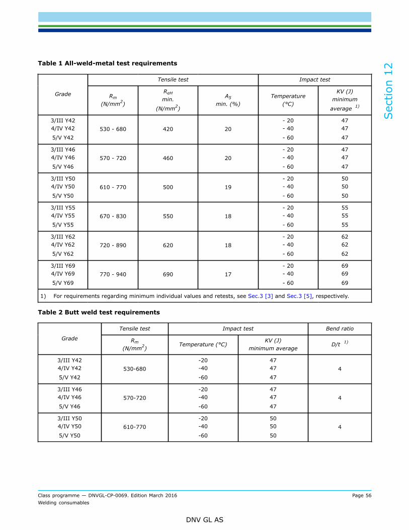
Sec
tion
12
Class programme — DNVGL-CP-0069. Edition March 2016 Page 56Welding consumables
DNV GL AS
Table 1 All-weld-metal test requirements
Tensile test Impact test
Grade Rm
(N/mm2)
ReH
min.
(N/mm2)
A5
min. (%)Temperature
(°C)
KV (J)minimum
average 1)
3/III Y424/IV Y42
5/V Y42530 - 680 420 20
- 20- 40
- 60
4747
47
3/III Y464/IV Y46
5/V Y46570 - 720 460 20
- 20- 40
- 60
4747
47
3/III Y504/IV Y50
5/V Y50610 - 770 500 19
- 20- 40
- 60
5050
50
3/III Y554/IV Y55
5/V Y55670 - 830 550 18
- 20- 40
- 60
5555
55
3/III Y624/IV Y62
5/V Y62720 - 890 620 18
- 20- 40
- 60
6262
62
3/III Y694/IV Y69
5/V Y69770 - 940 690 17
- 20- 40
- 60
6969
69
1) For requirements regarding minimum individual values and retests, see Sec.3 [3] and Sec.3 [5], respectively.
Table 2 Butt weld test requirements
Tensile test Impact test Bend ratio
Grade Rm
(N/mm2)Temperature (°C)
KV (J)minimum average
D/t 1)
3/III Y424/IV Y42
5/V Y42530-680
-20-40
-60
4747
474
3/III Y464/IV Y46
5/V Y46570-720
-20-40
-60
4747
474
3/III Y504/IV Y50
5/V Y50610-770
-20-40
-60
5050
504

Sec
tion
12
Class programme — DNVGL-CP-0069. Edition March 2016 Page 57Welding consumables
DNV GL AS
Tensile test Impact test Bend ratio
Grade Rm
(N/mm2)Temperature (°C)
KV (J)minimum average
D/t 1)
3/III Y554/IV Y55
5/V Y55670-830
-20-40
-60
5555
555
3/III Y624/IV Y62
5/V Y62720-890
-20-40
-60
6262
625
3III Y694/IV Y69
5/V Y69770-940
-20-40
-60
6969
695
1) D = mandrel diameter, t = specimen thickness
The chemical analysis of the deposited weld metal in each test assembly shall be supplied by themanufacturer and shall include the content of all significant alloying elements.
2 Annual testsDepending on whether it concerns electrodes, wire/flux combination or wire/gas combinations, the testingshall be carried out according to that prescribed in Sec.4 [6], Sec.5 [5] or Sec.7 [5], respectively. The testresults shall, however, comply with the requirements given in Table 1. The chemical composition of thedeposited weld metal shall be determined and submitted for a review.For fillers with Mark H10 and Mark H5 one hydrogen test is required.

Sec
tion
13
Class programme — DNVGL-CP-0069. Edition March 2016 Page 58Welding consumables
DNV GL AS
SECTION 13 WELDING CONSUMABLES FOR WELDING OFAUSTENITIC AND NON-MAGNETIC STAINLESS STEELS
1 GeneralApproval of welding consumables for austenitic stainless steels will be considered subject to compliance withthe specified tests and requirements in [2] to [5].Parent plate material should preferably have a composition matching that of the electrode to be tested. Mildsteel plates may, however, be applied provided that the groove faces are clad with at least two runs by thewelding consumable which shall be tested.
2 All-weld-metal testPreparation of test assemblies:Two all-weld-metal test assemblies shall be prepared as shown in Figure 1, one using a Ø2.4-3.25 mmelectrode and the other using the largest size manufactured.For wire/gas combinations the wire size shall be Ø1.2 mm and the largest size manufactured.For flux cored wire combinations the wire size shall be Ø1.2 or 1.6 mm and the largest size manufactured.For wire/flux combinations the smallest and largest size manufactured shall be tested.The weld metal shall be deposited in accordance with normal welding practice. The direction of depositionshall be reversed between subsequent layers, each bead not being wider than 4 times the core wire diameterand not exceeding 4 mm in thickness. Between each run, the assembly shall be left in still air until it hascooled below 100°C, the temperature being checked in the middle of the weld bead surface.Test specimens:Depending on the service temperature, the number of test specimens taken according to Figure 1 is asfollows:
— service temperature below -105°C; two longitudinal tensile and three impact test specimens shall betaken.
— service temperature above -105°C; two longitudinal tensile test specimens only shall be taken.
The test specimens shall be prepared according to Sec.3 [4].

Sec
tion
13
Class programme — DNVGL-CP-0069. Edition March 2016 Page 59Welding consumables
DNV GL AS
Figure 1 Test assemblies (all measures in mm)
Test requirements:The test results shall comply with the requirements given in Table 1. Welding consumables intended for lowtemperature service shall be impact tested at -196°C (or other temperatures below -105°C). The averageimpact value for the three specimens is not to be less than 27J.
3 Butt weld test:The butt-weld tests shall be welded as specified in [4] (covered electrodes), [5] (wire/flux combinations) or[7] (wire/gas combination). The transverse tensile, impact and bend test shall be carried out.The results of transverse tensile test shall comply with the requirements of Table 3.Impact test specimens are normally not required for service temperature above -105°C. If servicetemperature below -105°C the impact test shall be performed at -196°C with average energy 27J.Testing for hot cracks shall be performed as specified in item Sec.3 [4.4].
4 Chemical compositionChemical analysis shall be carried out for all dimensions of welding consumables manufactured. The analysisshall be carried out as stipulated in Sec.10 [4] and shall be reported for approval.The chemical composition of the core wire shall be reported.Test requirements:The chemical composition of the weld metal shall be in the range given in Table 2.

Sec
tion
13
Class programme — DNVGL-CP-0069. Edition March 2016 Page 60Welding consumables
DNV GL AS
5 Corrosion TestTesting of resistance to intergranular corrosion (IC) shall be performed on test specimens with intersectingbutt welds using the copper sulphate - sulphuric acid method (Strauss test). No cracks may be detected andthe metallographically measured depth of penetration of the attack at the grain boundaries shall not exceed0.05 mm.In the case of special corrosion conditions or particular materials, the Society may require other corrosiontests as an additional or alternative measure.
Table 1 All-weld-metal test requirements 1)
Electrode gradeYield stress, Rp0.2
min
(N/mm2)
Tensile strength, Rm,min
(N/mm2)
Elongation, A5min. (%)
VL 308 Mo 290 550 25
VL 308 290 550 25
VL308 L 270 520 25
VL 309 290 550 25
VL 309 L 270 520 25
VL 309 Nb 290 550 22
VL 309 Mo 290 550 25
VL 309 MoL 270 520 25
VL 310 290 550 22
VL 310 Nb 290 550 18
VL 310 Mo 290 550 22
VL 312 350 660 16
VL 316 290 550 22
VL 316 L 270 520 22
VL 317 290 550 22
VL 317 L 270 520 22
VL 318 290 550 18
VL 330 270 520 18
VL 347 290 550 22
VL 349 360 690 18
1) The values for reduction of area to be reported for information
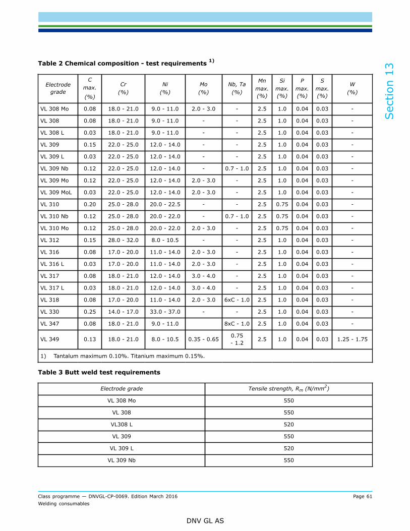
Sec
tion
13
Class programme — DNVGL-CP-0069. Edition March 2016 Page 61Welding consumables
DNV GL AS
Table 2 Chemical composition - test requirements 1)
Electrodegrade
Cmax.
(%)
Cr(%)
Ni(%)
Mo(%)
Nb, Ta(%)
Mnmax.(%)
Simax.(%)
Pmax.(%)
Smax.(%)
W(%)
VL 308 Mo 0.08 18.0 - 21.0 9.0 - 11.0 2.0 - 3.0 - 2.5 1.0 0.04 0.03 -
VL 308 0.08 18.0 - 21.0 9.0 - 11.0 - - 2.5 1.0 0.04 0.03 -
VL 308 L 0.03 18.0 - 21.0 9.0 - 11.0 - - 2.5 1.0 0.04 0.03 -
VL 309 0.15 22.0 - 25.0 12.0 - 14.0 - - 2.5 1.0 0.04 0.03 -
VL 309 L 0.03 22.0 - 25.0 12.0 - 14.0 - - 2.5 1.0 0.04 0.03 -
VL 309 Nb 0.12 22.0 - 25.0 12.0 - 14.0 - 0.7 - 1.0 2.5 1.0 0.04 0.03 -
VL 309 Mo 0.12 22.0 - 25.0 12.0 - 14.0 2.0 - 3.0 - 2.5 1.0 0.04 0.03 -
VL 309 MoL 0.03 22.0 - 25.0 12.0 - 14.0 2.0 - 3.0 - 2.5 1.0 0.04 0.03 -
VL 310 0.20 25.0 - 28.0 20.0 - 22.5 - - 2.5 0.75 0.04 0.03 -
VL 310 Nb 0.12 25.0 - 28.0 20.0 - 22.0 - 0.7 - 1.0 2.5 0.75 0.04 0.03 -
VL 310 Mo 0.12 25.0 - 28.0 20.0 - 22.0 2.0 - 3.0 - 2.5 0.75 0.04 0.03 -
VL 312 0.15 28.0 - 32.0 8.0 - 10.5 - - 2.5 1.0 0.04 0.03 -
VL 316 0.08 17.0 - 20.0 11.0 - 14.0 2.0 - 3.0 - 2.5 1.0 0.04 0.03 -
VL 316 L 0.03 17.0 - 20.0 11.0 - 14.0 2.0 - 3.0 - 2.5 1.0 0.04 0.03 -
VL 317 0.08 18.0 - 21.0 12.0 - 14.0 3.0 - 4.0 - 2.5 1.0 0.04 0.03 -
VL 317 L 0.03 18.0 - 21.0 12.0 - 14.0 3.0 - 4.0 - 2.5 1.0 0.04 0.03 -
VL 318 0.08 17.0 - 20.0 11.0 - 14.0 2.0 - 3.0 6xC - 1.0 2.5 1.0 0.04 0.03 -
VL 330 0.25 14.0 - 17.0 33.0 - 37.0 - - 2.5 1.0 0.04 0.03 -
VL 347 0.08 18.0 - 21.0 9.0 - 11.0 8xC - 1.0 2.5 1.0 0.04 0.03 -
VL 349 0.13 18.0 - 21.0 8.0 - 10.5 0.35 - 0.65 0.75- 1.2 2.5 1.0 0.04 0.03 1.25 - 1.75
1) Tantalum maximum 0.10%. Titanium maximum 0.15%.
Table 3 Butt weld test requirements
Electrode grade Tensile strength, Rm (N/mm2)
VL 308 Mo 550
VL 308 550
VL308 L 520
VL 309 550
VL 309 L 520
VL 309 Nb 550

Sec
tion
13
Class programme — DNVGL-CP-0069. Edition March 2016 Page 62Welding consumables
DNV GL AS
Electrode grade Tensile strength, Rm (N/mm2)
VL 309 Mo 550
VL 309 MoL 520
VL 310 550
VL 310 Nb 550
VL 310 Mo 550
VL 312 660
VL 316 550
VL 316 L 520
VL 317 550
VL 317 L 520
VL 318 550
VL 330 520
VL 347 550
VL 349 690
6 Austenitic welding consumables for welding of non-magneticstainless steelsTesting is performed in analogous manner as described in items [2] to [5] and comply with the requirementsof Table 5 and Table 6.Welding consumables for welding of non-magnetic stainless steels are approved according to a quality gradecorresponding to the chemical composition (material no.) of the weld metal. Table 4 contains a number ofexamples. The testing and approval of steel in the left-hand column encompasses the steel(s) in the right-hand column, subject to separate consideration of the corrosion conditions in each case.
Table 4 Austenitic welding consumables for welding of non-magnetic stainless steels
Grade Testing and approval relating to steel 1) Steels covered by the approval 1)
Designation Mat. No. Designation Mat. No.
3954 X2CrNiMnMoNNb21-16-5-3 1.3964 X4CrNiMnMoN19-13-8X2CrNiMoN22-15
X2CrNiMoN18-14-3
X2CrNiMo18-15
1.39481.3951
1.3952
1.3953
3984 X2CrNiMnMoNNb23-17-6-3 1.3974 X2CrNiMnMoNNb21-15-7-3X2CrNiMoN22-15
X2CrNiMoN18-14-3
X2CrNiMnMoNNb21-6-5-3
1.39141.3951
1.3952
1.3964
1) Steels in accordance with the BWB Material Performance Sheets having the corresponding material number.

Sec
tion
13
Class programme — DNVGL-CP-0069. Edition March 2016 Page 63Welding consumables
DNV GL AS
Table 5 All weld metal test requirements
Minimumyield strength Tensile strength Minimum
elongationMinimum notchimpact energy Test temperature
Grade
(N/mm2) (N/mm2) (%) (J) 1) (°C)
39543984
430510
700 – 950850 – 1050
30 70 (49) + 20
1) Means value of three specimens; for individual values 49J requirement applies
Table 6 Chemical composition requirements
GradeC
max.
(%)
Cr(%)
Ni(%)
Mo(%)
Mn%
Simax.(%)
Pmax.(%)
Smax.(%)
N(%)
Nb(%)
3954 0.03 21.0-23.0 16.0-19.0 3.4-4.0 7.0-9.0 1.0 0.025 0.015 0.15-0.35
3984 0.03 21.0-23.5 15.5-18.0 4.5-6.5 1.0 0.025 0.010 0.3-0.5 0.10-0.30
7 Annual testDepending on whether it concerns electrodes, wire/flux combination or wire/gas combinations, the testingshall be carried out according to that prescribed in Sec.4 [6], Sec.5 [4] or Sec.7 [5], respectively.For welding consumables which are not intended for low temperature service impact test is not required.Annual testing for welding consumables which are intended for low temperature service at -105°C or lowerimpact testing at the respective temperature shall be performed.Chemical composition analysis of two different dimensions shall be carried out.
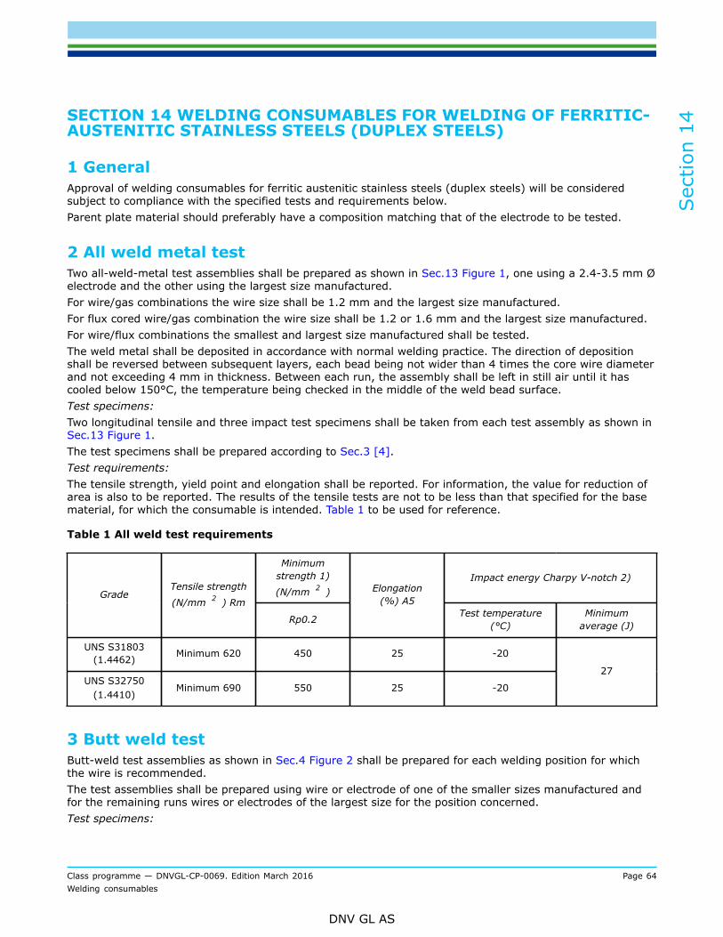
Sec
tion
14
Class programme — DNVGL-CP-0069. Edition March 2016 Page 64Welding consumables
DNV GL AS
SECTION 14 WELDING CONSUMABLES FOR WELDING OF FERRITIC-AUSTENITIC STAINLESS STEELS (DUPLEX STEELS)
1 GeneralApproval of welding consumables for ferritic austenitic stainless steels (duplex steels) will be consideredsubject to compliance with the specified tests and requirements below.Parent plate material should preferably have a composition matching that of the electrode to be tested.
2 All weld metal testTwo all-weld-metal test assemblies shall be prepared as shown in Sec.13 Figure 1, one using a 2.4-3.5 mm Øelectrode and the other using the largest size manufactured.For wire/gas combinations the wire size shall be 1.2 mm and the largest size manufactured.For flux cored wire/gas combination the wire size shall be 1.2 or 1.6 mm and the largest size manufactured.For wire/flux combinations the smallest and largest size manufactured shall be tested.The weld metal shall be deposited in accordance with normal welding practice. The direction of depositionshall be reversed between subsequent layers, each bead being not wider than 4 times the core wire diameterand not exceeding 4 mm in thickness. Between each run, the assembly shall be left in still air until it hascooled below 150°C, the temperature being checked in the middle of the weld bead surface.Test specimens:Two longitudinal tensile and three impact test specimens shall be taken from each test assembly as shown inSec.13 Figure 1.The test specimens shall be prepared according to Sec.3 [4].Test requirements:The tensile strength, yield point and elongation shall be reported. For information, the value for reduction ofarea is also to be reported. The results of the tensile tests are not to be less than that specified for the basematerial, for which the consumable is intended. Table 1 to be used for reference.
Table 1 All weld test requirements
Minimumstrength 1)
(N/mm 2 )Impact energy Charpy V-notch 2)
GradeTensile strength
(N/mm 2 ) Rm
Rp0.2
Elongation(%) A5
Test temperature(°C)
Minimumaverage (J)
UNS S31803(1.4462) Minimum 620 450 25 -20
UNS S32750(1.4410)
Minimum 690 550 25 -20
27
3 Butt weld testButt-weld test assemblies as shown in Sec.4 Figure 2 shall be prepared for each welding position for whichthe wire is recommended.The test assemblies shall be prepared using wire or electrode of one of the smaller sizes manufactured andfor the remaining runs wires or electrodes of the largest size for the position concerned.Test specimens:
Sec
tion
14
Class programme — DNVGL-CP-0069. Edition March 2016 Page 65Welding consumables
DNV GL AS
One transverse tensile, two bend and three impact test specimens shall be taken from each test assembly asshown in Sec.4 Figure 2.The test specimens shall be prepared according to Sec.3 [4].Test requirements:The result of the transverse tensile test is not to be less than that specified for the base metal, for which theconsumable is intended.The impact test specimens shall be tested at -20°C and minimum average impact energy shall be 27 J for fullsize test specimens.The bend test specimens can be considered as complying with the requirements if, after bending, no crack ordefect having any dimension exceeding 3 mm can be seen on the outer surface of the test specimen.If requested testing for hot cracks to be performed as specified in item Sec.3 [4.4].
4 Chemical compositionChemical analysis shall be carried out for all dimensions of welding consumables manufactured. The analysisshall be carried out as stipulated in Sec.10 [4] and shall be reported for approval.The chemical composition of the core wire shall also be reported.
5 Microstructural examinationThe ferrite/austenite-ratio of the weld shall be determined in accordance with ASTM E562. The ferrite contentin average shall be in the range of 30 to 70%.
6 Corrosion testFor the determination of pitting and crevice corrosion resistance, one test according to ASTM G48, Method Ais required. The 25Cr test specimen shall be exposed to the solution at a constant temperature of 40°C for24 hours. The 22Cr test specimen shall be exposed to the solution at a constant temperature of 20°C for 24hours. No pitting attack shall be visible on the test faces at 20X magnification, and the general weight lossshall be less than 4.0 g/m2.In the case of special corrosion conditions or particular materials, the Society may require other corrosiontests as an additional or alternative measure.
7 Annual testsDepending on whether it concerns electrodes, wire/flux combination or wire/gas combinations, the testingshall be carried out according to that prescribed in Sec.4 [6], Sec.5 [4] or Sec.7 [5], respectively.Chemical composition analysis of two different dimensions shall be carried out.

Sec
tion
15
Class programme — DNVGL-CP-0069. Edition March 2016 Page 66Welding consumables
DNV GL AS
SECTION 15 WELDING CONSUMABLES FOR WELDING OFALUMINIUM ALLOYS FOR GENERAL AND LOW-TEMPERATURESERVICE
1 GeneralApproval of welding consumables for aluminium alloys will be considered subject to compliance with thespecified tests and requirements in [2] and [3].The welding consumables shall have a suitable hardness andsmooth surface free from slivers, depressions, scratches or foreign matters that would adversely affect thewelding properties when operating the welding equipment.Tolerances for dimensions shall be kept within the limits guaranteed in the manufacturer’s specifications.The recommended and used composition for the shielding gases shall be reported.
2 Deposited weld metal testFor the testing of the chemical composition of the deposited weld metal, a test piece according to Figure 1shall be prepared. The size depends on the type of the welding consumable (and on the welding process)and shall give a sufficient amount of pure weld metal for chemical analysis. The base metal used shall becompatible with the weld metal in respect of chemical composition.
Figure 1 Deposited weld metal test assembly
The chemical composition of the deposited weld metal shall be determined.. The results of the analysis shallnot exceed the limit values specified by the manufacturer.
3 Butt weld testThe testing of the welded joints shall be performed on butt-weld test assemblies according to Figure 2 andFigure 3 made in an analogous manner to Sec.4 [3], Sec.5 [2.2], Sec.7 [2.2] or Sec.7 [3.2] respectively.
Butt weld test assemblies according to Figure 2 with a thickness of 10 to 12 mm shall be prepared for eachwelding position (down hand, horizontal-vertical, vertical-upward and overhead) for which the consumableis recommended by the manufacturer; except that consumables satisfying the requirements for down handand vertical-upward positions will be considered as also complying with the requirements for the horizontal-vertical position subject to the agreement of the Society.
Additionally one test assembly according to Figure 3 with a thickness of 20 to 25 mm shall be welded in thedown hand position only.
T = Flat tensile test specimenBC = Face bend test specimenBR = Root bend test specimen

Sec
tion
15
Class programme — DNVGL-CP-0069. Edition March 2016 Page 67Welding consumables
DNV GL AS
M = Macrographic section
Notes:
1) Edge preparation shall be single V or double V with 70° angle.2) Back sealing runs are allowed in single V weld assemblies.3) In case of double V assembly both sides shall be welded in the same welding position.
Figure 2 Butt weld test assembly for positional welding
1) Edge preparation shall be a single V with 70º angle.2) Back sealing runs are allowed.
Figure 3 Additional butt weld test assembly in down hand position
On completion of welding, assemblies must be allowed to cool naturally to ambient temperature.
Welded test assemblies and test specimens must not be subjected to any heat treatment.

Sec
tion
15
Class programme — DNVGL-CP-0069. Edition March 2016 Page 68Welding consumables
DNV GL AS
6000 series assemblies should be allowed to naturally ageing for a minimum period of 72 hours from thecompletion of welding before testing is carried out.
The test specimens shown in Figure 2 and Figure 3 shall be taken from the butt weld test assemblies.
The test specimens shall be prepared according to Sec.3 [4].
The tensile strength shall comply with the requirements specified in the Table 1. Yield point and elongationshall be reported for the Society's consideration. The yield strength for both weld metal and welded jointshall not be less than that specified for the parent material (in soft condition), for which the consumableis intended. For materials in deformation hardened or aged condition, the choice of consumable andrequirements to mechanical properties shall be evaluated in each particular case.
Table 1
Alloy Filler Tensile strength R m ,minimum (N/mm 2 )
VL-5754 5356, 5183 190
VL-5086 5356, 5183 240
VL-50835183
5356, 5183
5356, 5183
275275
275
VL-5383 or VL-5456 5183 290
VL-5059 5183 330
VL-6061 5356, 5183 170
VL-6005A 5356, 5183 170
VL-6082 5356, 5183 170
The bend test specimens shall be bent on a mandrel with maximum diameter as given in the formula below.The bending angle shall be at least 180°. After bending, the test specimens shall not reveal any open defectsin any direction greater than 3 mm. «Wrap around» bending is the preferred bending method.
(1)
where
d = maximum former diameterts = thickness of the bend test specimen (this includes side bends)A = minimum tensile elongation required by the material specification (for combination between
different alloys, the lowest individual value shall be used)
The macrographic specimen shall be examined for imperfections such as lack of fusion, cavities, inclusions,pores or cracks.
4 Annual testsThe annual tests shall entail the preparation and testing of the deposited weld metal test assembly asprescribed under [2] (Figure 1) and of the down hand butt weld test assembly according to [3] (Figure 2).

Sec
tion
16
Class programme — DNVGL-CP-0069. Edition March 2016 Page 69Welding consumables
DNV GL AS
SECTION 16 WELDING CONSUMABLES FOR COPPER AND COPPERALLOYS
1 GeneralApproval of welding consumables for copper alloys will be considered subject to compliance with the specifiedWelding consumables for welding of copper and copper alloys are classified into the quality grades shown inTable 1 on the basis of the chemical composition (type of alloy) and mechanical (strength) properties.
— SCU1 Al-bronze or Mn-bronze;— SCU2 Al-bronze or Ni-Mn-bronze;— SCU3 Al-bronze, Ni-Al-bronze or Mn-Al-bronze;— SCU4 Mn-Al-bronze.
2 All weld metal testOnly one all weld test piece to be welded in the down-hand position. Testing of the all weld test assemblyshall consist of two longitudinal tensile tests. Tensile strength, yield strength and elongation shall comply withthe requirements specified in Table 1.
Table 1 Welding consumables for copper and copper alloys
Quality grade Minimum 0,2 %-proof stress
[N/mm²]
Tensile strength
[N/mm²]
Minimum elongation
[%]
CuNi30Fe
CuNi30Mn
120
120
360-490
360-490
30
30
SCU1
SCU2
SCU3
SCU4
175
195
245
275
370 min.
410 min.
500 min.
550 min.
20
20
16
18
3 Butt weld testTesting of the butt weld test assembly shall be performed in a manner analogous to that prescribed inSec.15 [3] (Sec.15 Figure 2) as in the case of aluminium alloys. The tensile strength shall comply with therequirements of Table 1.
The bend test specimens shall be bent on a mandrel with maximum diameter as given in the equation below.The bending angle shall be 180°. After bending, the test specimens shall not reveal any open defects in anydirection greater than 3 mm.
(1)
where
d = maximum former diameterts = thickness of the bend test specimen (this includes side bends)A = minimum tensile elongation required by the material specification (for combination between
different alloys, the lowest individual value shall be used).

Sec
tion
16
Class programme — DNVGL-CP-0069. Edition March 2016 Page 70Welding consumables
DNV GL AS
4 Chemical compositionFor determination of the chemical composition, ASTM E478 shall be used. For copper-nickel alloys ASTM E 75shall be applied. At least two dimensions shall be tested.
5 The chemical composition shall not exceed the limits specified bythe manufacturer. Annual testsThe annual tests shall entail the preparation and testing of a butt-weld test piece in accordance with [3]welded in the down-hand position.

Sec
tion
17
Class programme — DNVGL-CP-0069. Edition March 2016 Page 71Welding consumables
DNV GL AS
SECTION 17 WELDING CONSUMABLES FOR NICKEL AND NICKELALLOYS
1 GeneralApproval of welding consumables for nickel and nickel alloys will be considered subject to compliance withthe specified tests and requirements in [2] and [3].Welding consumables for nickel and nickel alloys are classified by the alloy type and on the basis of thechemical composition and mechanical (strength) properties.Parent plate material should have a composition matching that of the consumable to be tested.Test plan shall be submitted for a review and verification prior start of approval process. The Society mayrequire other tests to be performed or stipulate other values for the required properties if they are moreappropriate to the character of the welding consumables or are necessitated by the intended use of thematerial.
2 All weld metal testDepending on the nature of the welding consumables and welding process, the test assembly shall be weldedand tested as specified in corresponding items Sec.4 (covered electrodes), Sec.5 (wire/flux combinations) orSec.7 (wire/gas combination). Impact testing is required only if consumable is intended for low temperatureapplication.The yield stress and tensile strength of the weld deposit shall be at least equal to the parent material tensileproperties. The average and single Charpy V-notch toughness shall not be less than specified for the type ofalloy at the corresponding test temperature.
3 Butt weld testDepending on the nature of the welding consumables and on the welding process concerned the testassembly shall be welded as specified in corresponding items Sec.4 (covered electrodes), Sec.5 (wire/fluxcombinations) or Sec.7 (wire/gas combination) and tested as specified herein.Test specimens:One transverse tensile, two transverse bend tests shall be taken from each test assembly. Longitudinal facebend may be required in addition.If the composition and mechanical properties of the deposited metal differ markedly from the compositionand properties of the base metal, the two transverse bend tests may be replaced by longitudinal bend tests.If this is done, one face bend and one root bend test shall be carried out. Longitudinal bend test then shall becarried out as specified in Sec.11 [2].Impact test shall be carried out if approval is requested for low temperature applications. Suitability of theconsumable for low-temperature applications is indicated separately in the approval certificate.The tensile strength and impact test results shall not be less than specified for the type of alloy. The bendtests shall not disclose any open defects in any direction exceeding 3 mm.
4 Chemical compositionChemical analysis shall be carried out for all dimensions of welding consumables manufactured. The analysisshall be carried out as stipulated in Sec.10 [3] and shall be reported for approval.The results of the analysis shall not exceed the limits specified in the standards or by the manufacturer, thenarrower tolerances being applicable in each case. The chemical composition of the core wire shall also bereported.

Sec
tion
17
Class programme — DNVGL-CP-0069. Edition March 2016 Page 72Welding consumables
DNV GL AS
5 Annual testThe annual tests shall entail the preparation and testing of all weld test piece in accordance with [2] weldedin the down-hand position. Chemical composition analysis of two different dimensions shall be carried out.

Sec
tion
18
Class programme — DNVGL-CP-0069. Edition March 2016 Page 73Welding consumables
DNV GL AS
SECTION 18 STANDARDS REFERRED TO IN THIS DOCUMENT
1 Referred standards— ISO 3690 - Welding and allied processes - Determination of hydrogen content in ferritic steel arc weld
metal— AWS A4.3 – Standard Methods for Determination of the Diffusible Hydrogen Content of Martensitic,
Bainitic, and Ferritic Steel Weld Metal Produced by Arc Welding— ASTM E478 Standard Test Methods for Chemical Analysis of Copper Alloys— ASTM E75 Standard Test Methods for Chemical Analysis of Copper Nickel and Copper Nickel Zinc Alloys— ASTM E562 Standard Test Method for Determining Volume Fraction by Systematic Manual Point Count.

Cha
nges
– h
isto
ric
Class programme — DNVGL-CP-0069. Edition March 2016 Page 74Welding consumables
DNV GL AS
CHANGES – HISTORICThere are currently no historical changes for this document.

DNV GLDriven by our purpose of safeguarding life, property and the environment, DNV GL enablesorganizations to advance the safety and sustainability of their business. We provide classification andtechnical assurance along with software and independent expert advisory services to the maritime,oil and gas, and energy industries. We also provide certification services to customers across a widerange of industries. Operating in more than 100 countries, our 16 000 professionals are dedicated tohelping our customers make the world safer, smarter and greener.
SAFER, SMARTER, GREENER