doc d~~ sl.oo. 'f foj{ official use only tr 1210-50the set is design d to give reliable communi...
TRANSCRIPT

\
)
Doc D~~ Sl.oo. 'f FOJ{ OFFICIAL USE ONLY TR 1210-50
1-2
TIDUllNH 'AL lU!]G(JLATION~ l -WAlt Dl ';rA lt'l 'l\I.lj]N'l',
No. 1210-50 r W Ai:>HINGTON, J?bty Ii , 1IIJ:Z.
RADIO SETS, TYPES SCR-131 AND SCR-161
P repared under di rection of the Chief Signa! Officer
r aragl'aphs ~ I ':<':T I ON r. C c n l'l'lIl u::;e lI lld lie::;el' ipt ioll ________ ________________________ 1-3
11. Instli li atioJl for ~eryk('______________ _____ ______ ____ ____ __ 4-5 I II. Olleru tion___ _____ _____________ ______ __________________ __ ___ 0- 7 IV. UCllloval from ::;ervicc_____ ________________________________ _ 8--9
V. Function of llarts _____ _______________________ . _ ___________ 1O~11 VI. Oll re, ael ju.-tment, ma intenance, and repaiL __________ __ _____ 12--14
VII. List of purts______ __ __ __________ __________ ________________ 15
!::l~;<':T.I.ON I
G IGNl!JItAL U~l~ AND Dl!J~CH,U"1'ION l 'al'agL'aph
~sos ________________________________ _________ _________ -------_ ____ _____ ____ 1 Gell om! d c"c ri pi iO[l ______ __________________ ____ __ ___ _____ __ __ ____ ____ ________ 2 I ll ustrat~us ___ _______ ____ _______________________ ___ ______ ~___ __ ____ __ _______ 3
1. Uses.- (l" Radio set, type SO.e.-131, is a por table, loop, continuous wave (C. "V.) te legraph tran 'mitting tlnd recei l'ing set operating within a frequcncy baJld of 3,960 to 4,360 ki locycles. The set is design d to give reliable communication between headquar ters which are separated by a elistance of 5 miles or less. It is also designcd to f urni sh 40 operating channels spaced 10 kilocycles apart; however, in order to avoW possible inter ference between nets it i s desirable so to assign frequencies as to haye nets which operate within 5 miles of Olie anoth er spaced at least 20 kilocycles apar t. 'r he set requ ires only two men to carry it. When set up, it occupies li ttle space and can be used in any location f rom which satisfnctory radin.tion may be expected.
b. Rael io set , type SCR-1G1, is iclenticnl with rnelio et, type SOR-131, except fot' t he capncities of three cnpaci tors, which c1ifCerence cnuses the former to opernte within n. f requency band of 4,370 to 5,100 kilocycle. . It is c1esignetl to furn i 'h 74 operati ll g channels spaced 10 kiloCyclcs apa r t; l!oweyer, in order to avoid possib le intcrfe rencc between nets it is desirable so to assign frequen 'ie,' ns to 1.J:1I'e nets which operute within 5 miles of one nnother spaced at least 20 kil ot.ycles apart. I n these regulat ion. all genera l statements apply to bot 11 H IC l'all io sets, types SOIt-131 and SOI1,.-161. Whcre settings, values, or type nUlli bers for these scts el iITe 1', those shown in parentheses apply to the rad io set, type SCR-1G1, only.
2. Gen eral description.-a. When packed for transportation, the set consists of foul' par ts : The radio recciver and transmitter, type BC-148 (BC-151), with a calT~' i ng strap, type S'1'- 19, wcighing when complete with bntteries, head sets, a nd tubes, 33.5 pounds and being 14frr inChes high , 14112 incbes wide, an d S ill inches decp; t he bag, type BG-49, conta in ing the loop, type LP- 7, the
114u37'-32--1

...
TR 1210-50 2-4 l{ADIO SETS, TYPES SCB-13 1 AND SCR-161
three legs ::tnd two cranks of the generator, type GN-35, and with its contents weighing!) pounds; the case, type CS-41, containing the generator, type GN-35, and weighing with it, 22 pounds ; the bag, type DG-50, weighing when packed 12 pouncls and containing three .'pare bal teries, type BA-23, two spare batteries, type BA-2, two spare tubes, t:),pe V1'-25 , three spare tubes, type V'1'-24, one co rd, type CD- 10, message books, etc. ~l' il e total weight of the set is 76.5 pOUll! i8.
Ii . When .. et up for operal"ion, the set consis ts of two essential parts : The rad io receiver ::tnd tran.'mitter, type BU--148 (BC-151), with loop, I.~·pe LP-7, attached, nnd the generator, type GN-3G. '1'he cord, type CD-103, connects the generator to the set box. 'J'he top 01' the loop is 57% inches aboye the leyei or the ground upon which the set resl!'; .
FWUHl'; l. - Hllclio set, lype SClt- li.l1 (161 ), se t up for opernti on
3. Illustrations.-Figlll'e 1 show.' a nOl'mul installation or the rmlio set ready to operate; bags, types BG-50 and BG-49, are shown under the generator a nd behincl the loop, respectively. Other views of the radio receiver and transmitter appear in Figures 2, 3, 4, a nd 5. li'igures 6 to 11 show various details of the ci I'cuit.' u tililled in the set.
SECTLON II
INS1'ALLA'1'ION l<'OR SERVICE Paragrapli
Detailed description of the set us issurd ______________ ___ ____ ___ _____ _____ ______ 4 Install illg the set_________________ ____________________ ___ ____ __ ___ _ ________ __ u
4. Detailed description of the set as issued.-a, RacUo reoei~er c£n(l /,l'a Il-8-
mitter, tV1)e lJO-148 (lJO- 151) .- (1) The radio receiver und transmitter con:;ist
2

RADIO SETS, 1'YPES SCR-131 AND SCR-161 TR 1210-50
4
of two wooden boxes permanently hinged together and held cIa 'ed for t ran'portation by two catches, one a t each sicIe. 'rhe smaller box wtll hereafter be called the appar atus box amI the larger box the battery compurtment box. The r acI io receiver uncI transmitter having been placed so that the battery compartment box rests on the ground, the catches which lock the two boxes together having been released, the apparatus box mny be swung up and bac];: on Ihe hinges so that it re.ts upon the projecting po rtion of the battery-compartment box. Fignre 2 shows the r adio receiver and transmitter in this opened position. On the panel of the apparatus box can be seen the receiver tuning control RECEIVER, the loop tuning control LOOP, and the filament rheostat l!~IL. RIIEOs'rA1" nil ']eal'ly marked. In Ihe UPller center of Ihe pn nel is a
FlGUHE :!.- H1.lUi o L'cceiyel' unc1 lnL DKwitteL'. type BC-H.8( 1511. f l'ont view
lla~h- l ight bu lb which light~ when the ~et is transmitting. Just above the center at the right is seen a socket fo r the 4-prong plug of the cord, type CD-103, which is used to connect the generator to the radio receiver and transmitter. At the bottom of the punel ancI nearly in the center is the filament current ammeter for the receiver ; of the scale of this meter there is visible onl y a small sector about the Illark which shows the correct position of the painter fOr proper receiver filam ent cUl'J'ent. The cord connecting the key to the panel need never be di sconnected except for purpose' of replacemen t. At the upper right aml left of the panel are seen t he catches which lock the panel to the apparatus box. Releasing these cMches by tur tling them so that the hamlles lire toward one another, the panel which i s hinged t1! t the bottom may be pulled forward . The in .-ide of the apparatus box is then visible us in
3

TR 1210-50 4 RADIO SETS, TYPES SCft- 1 31 AND SCR-161
Figure 3. On the bottom of the panel i::; mounted the receiving apparatus except batteries, head sets, and loop. The panel is of metal and when clo. 'ed makes a spring contact with the sides of a metal box which fil ls the lower part of the apparatus box; the receiving apparatus except the batteries, head sets, and loop is thus contained within a mctal shie1c1. From left to right across the bottom of the panel, the major items of equipment visible are tbe receiver tuning capncitor, behind which nre mounted two cnpacitors, type CA.-165
PS -3 1-4 75
PIGUltE a.-RadiO rece iver and tmnsmitter, type BCH 8(lJ l), sholV ing interior of flPPll l"utus box
(CA.-169), and two capacitors labeled C. and C. in F igure 6; a cylindrical metal case which contains the griU. and plate inductors of the receiver heterodyne tube, the receiver heterodyne tube, in rear of which is the grid leak; two audio-frequency amplifier tubes and on the extreme right, two audio-frequency t ransformers, type C-65. On and above the shelf which divides the apparatus box in two are the transmitting t ube, relay, and nll t ransmitting equipment except the key, generator, loop, and loop-tuning capacitor. The transmitting tube is seen in the upper left; beneath it ure the transmitting reactor and [L
4

RADIO ,'ETS, TYPES SCR-13 1. AND SCR-16 I
TR 1210-50 4
capacitor, type CA-134; in the center is the transmitting relay ; at the right is the socket for the piug of the cord, type CD-I03. All tubes are on flexible mounti~gs so as to reduce danger of accident and to minimize microphonic noise.
(2) The shelf carrying the key, shown in Figure 2, has also upon it a wiring diagram of the set and a sheet of white celluloid beside the key fo r operator's 11encil memoranda; the celluloid can be erased with a damp cloth. The shelf is hingell at t he back allll is held ill place by a catch at the front; it affords access to the battery compartment box. Figure 4 shows the shelf raised and
RS.31. 56A SCR-1 31
o -NC'
F I GU I<~ 4.-Uauio receiver nut! tl'fl ll "mi ttcr, type llC-148(15i), SIIOW' iug interior of battery compa rtmen t box
gives a v iew of the battery compa rtment box. 'l'he tllree receiver filament bat· tel'ies, t~'pe BA-23, are connected in .. eries by means of the flexible cords provitleu and the resulting ba ttery is connected to the 4.5 V billding posts at the right cente r of the compal'tment. To the right of the filament battery are two batterics, type BA-2, which form the plate battery for the receiver; these batteries are connected in series by means of the binding posts directly in rear of t hem. Just beneath t ile rectangle 01' bakelite on which are mounted the binuing [losts is a doubl e jack 1'01' the hend sets, type P-ll. 'l'he j ack is open to the rear; nn open ing at the uppcr ri ;;ht rear of t he battery compartment box allows the conl s 01: the hend sets j'O be pH ss('d to the outside witll th e shelf down. 'rile
5

TR 1210-50 4 H A DID SFlTS, 'l'YPJ~S SOR-l 3 1. AND SOR-16l
hearl sets are ca rried in the real' of the hattery compar tment hox as shown in Figure 4. '1'0 the right oC the catch in Figures 2 and 4 i. seen a hOle in th e shelf' ; when the set is closed for tran, portatioll, a projection at the top of the panel in Figures 2 and 3 passes through t his Iiol e and ,trikes the spring switch in the battery compartment box, thus opening the receiver filament circuit when the set is packed fo r transportation.
(3 ) lcigure 5 shows the back of the radio receiver and transmitter and the two sockets fo r t he loop. The loop, type LP- 7, is not a part of the radio r eceiver and transmitter. It co·nsists of (wo pa rts; each 11tl1't i i'< a pair of lengths
::.
~-
SCR-131 PS.31.S6B
l!'IGUHE G.- Haclio receiver unci trunsmitter, type BC-14S (151), reur view
of square brass tubing permanently hinged together. The f ree end of one tube of each pail' plugs into one of the sockets on the radio receiver and transmitter; the free ends of the other tubes of each pail' snap together in a knife switch contact at the top of the loop. (See fi g'. 1.)
b. GeneJ'atol', t1ipe GN-3:j.-CUl'rent for the 11l ate and fil ament circuits of tIl e transmitting tube is furni shed by the generator, type GN-35. The latter is a self-excited generator hal'i ng a llouhl e-lVoullu a rmature and is eq uip[1cd with a voltage regulator. For H'-C, the gencrator is mountell on three removable legs, one of which carries a seat fo r t ile man who tUl'I1' the generator. 'rhe cranks by which the generator is t urned are al"o removable. No connections to the generator are requircd to be made other than plugging into it the plug 01'
the cord, type CD-l03.
6

RADIO SETS, l 'YPES SOR,-1 3 1 AN D SOR-16 1
TR 1210-50 4-5
C. Barl, tlme BG- 49.-This bag re embl es a golf bag cut in half along its longer (Iimension and fitterl with a h inged co'·er at the top. The bag is of canvas with web top and metal bottom; the top fa stens with an automobile curtain fas tener.
cl. Bag, tlJpe BG--..50.-This bag is of webbing wi th a hinged coyer which is held closed by automobil e curta in fasteners. Under the cover is a flap on the underside of whi ch nre marked the items to be carried in the various compartments into whi ch the bag is divided. At the ri ght of the bag as it is openell is a recta ngular fiber container for the spnre vacuum t ubes of the set; the tubes will not fit into this container in their original pasteboard cartons but should be Wr::ll)ped with the protectiYe tissue wi thin the paper carton when being pncked into the con tniner. To the left of the container [md ::I t the rea r of the bIlg are three compartmen t" each designed to hold one of the three spare batteri e. , t~· pe BA-23 ; to the left of these is a compartment de:igned to hold the two spare batterie". type BA-2 ; the fr ont compartment on the left i ,:; for the message book, log sheets, (' tc . . When the flap i: closed clown there is left enough spl1ce on the top of it to l)ack the cord, type CD- 103.
e. O(/,se, type OS-l1.-Thi: is a rectangul a r w('bbing case wit"h a leather rcinforced bottom and hinged cover held closed with two automohile curtain fa s teners. It sen es to 111"otect the genera tor during transportation and has no other purpose.
5. Installing the set.-a. Ra,clio 1'eceiver antl tmn '/11,U ter , tY1Je B O-148 (BO- 15J) .-(1) Place the radio receiver and t ran 'mittel' firmly on the ground with the battery compartment box down and the apparatus box toward the operator. Unfasten the catches a t I'he right and left by an upwa rd pull orl the latche;;. Raise the apparatus box to a vertical position so that it rests upon the projection of the battery compar tment box. Assemble the loop on the radio receiver and transmitter. The plane of the loop should point toward the most di stant station of I·he net Ot· toward th a t sta tion with which communication is expected to be most difficult. Unlatch and raise the , helf of the battery compartment box. Connec t in series, by means of th e flexible cords, three batteries, type BA-23, fit them in to the compar tment made for them ·and see that the positive and nega tiye terminals of the 3-cell battery are now connected to the proper bincling posts, +4.5 V and - 4.5 V, respectively. Put into the right-hand front compartment two batteries, type BA-2 ; connect the red wire of the right-hanel one to the + 45 V binding post l1nd the bl ack wire of the left-hand one to the - 45 V binding post; connect th e remaining wire of each battery to either of the binding posts ma rked COMMON B. The foregoing procedure of connecting the batteri es will be followed only wh en putting th e set into service for the first time, or for battery replacement or when the set has been withdrawn f rom s torage. Remove the head sets, plug them into th e jacks beneath the binding post pl1ne! and bring the cords of the head ~ets out through the slot at the right of the battery compartment box. Lower the shelf and lock it with the cl1tch.
(2) See tha t the filnm ent rheostat is in the OFF position. Tum the cl1tches at the top 01' the pnne! of I·he apparatus box until the hl1 ndle pOint toward one another and pull the panel forward. The panel will not pull forward easily; this is normal and results f rom the strong contac t which the panel makes with the box shielding the receiver circui t: . Insert in the transmitter tube socket a tube, type VT- 25; insert in the receiver tube socket · three tubes, type V,+,-24. If cet'tain tubes have been selected fo r the heteroclyne tube, care
7
.'.-~ .

TR 1210-50 5-6 RADIO SETS, TYPES SOR-1 3 1 AND SOH-H l
should be excrcised that onc of the.'c i.' pln CN1 in thc firs t r C(,C l\'lng tube sockct at thc left. Push the pancl back nnd lock it int o pl ac(' with t hc (':I tches, The forego ing procedure of' in.'crting tulJes will not be follo \\'ed C'xc:cpt' whC'1l t-he set is usell for thc fiLt time, for tuhc I'Cll l:1c:elllont, 0 1' aft e r t-he set has I)('en s tored ; a t other timcs the tuhe.' nrc, left in t he sockets,
(3) Sc row t he fla sh-li ght bulb in to its sockct in the conlc!' of thc p,l11el; t hi s also may be left in placc CXCOllt whell th c set is to IJc storcd , PIli):: into the socket at the upper right of the 11n1l01 one end of' thc ('orll , typc CD-l03; thc arrow 011 the plug should be a ligned with the arrow on thc socket, otherwise the plug \\'i1l not cnter t hc socket. 'I'hc ends of' th e cOl'll arC' int(')'C'hangeable,
(4) Tum the r eecil"el' filum nt r hcostat slowly unti l t he allJmctcr pOinteI' is aligned wi th the ar rOw in the, calc s lot.
b, Gcn e1'cLtoT, t!Jpe GN-85,- Hemovc the gcnerator and its lcgs f rom the C:ll'rying bags, Lay the generato r on til() gl'OUIHI with the name plate vertical an{l so that it 'a n bc reat1. Slip the lcgs which do n ot hav t Ile sea t attn chcll t hrougll the ri ngs on t he top of t he gencrator allLI engagc thcm firl1lly with the spring beyond the ring ', Ra ise the gcnerator upon t hc Icgs so tlia t thc namc plate is up, On tile vcrtical f ace of th e generator oppos i te the two attached legs i ' it D ring a nd I)encath t li e D ring a s lot. H olelillg lhc D rin'" up, enga~e the projection a t t il e bottom of' thc 111lper end of the third IC'g in tlie slot; tllen ])USIl t he D ring tlo\\'n over t ile top of t lie lc"', ltai ~c I Ile scat, rai sc tll c sea tholtl '1' and inser t tile f rce cnd of tile sca t holder into the, lot in t ile bottom o r the scat, In .'er t the cranks in t li c ho les at t li e ri gli t ant1 le rt of thc gener:It-or, .lust abovc L1 le top of tile two I gs of tlie genernto r i~ t li c socket ro r tile tord, typc CD-l0:J, l'lug into the socl(ct th e frce end of tllc co rd , t,VPl' (, D- 1m, '1' lle ]lIng wi ll cnter thc .'ockct: on ly wlion tile arrows on tlicm :Ire :I ligued,
SOOI'ION 1 I I
OPERA'l'ION Pal'a>:l'nph
Opern l in g pl'occc1ul'c fol' t he n et conirol 8Inl iOll __ __ _________________ _ _ ___ __ __ __ G
Opcraling Iroccdu l'~ I'O!' slatio ns o lhe l' than thc net con ll'ol s t"UOIl _____ __ ___ ___ __ __ 7
6, Operating procedure for the net control station,- (/" 'rul'll Lllc rC{'l' h '('I' aliju.' (.lllent to thc frC(ju ' licy assigned t lie lll' t in \\'liicli t Ile ~l't is to lI'ork. Direct t lic a.'si s tu ll t to t urn til(' gOll e rator at approximatcly GO to GO rc '-olution:-; ]ler minule; minimum prOpel' SLPed w ill bc ind icatcd to him by tll c secmingly easier turning of the generato r \\-hcn i t rcach es t.hc s]leod at \\'hich t he volt ag;c rcgu lator starts to function, Hold clown t ile sendin g key anel tum til e loop adjustmellt until zero brat is r cachcd, As thc adjustment a[lp roac ll's zero beat, it note of c1 cr ea.' ing f requc ll cy wi Il be h ea rd i n t hc hl'all phonc.'; if the adjustment passes zero bcat on the othel' .' ide, tbc note will agnin be ileaI'd but with i ll creasing pit'ch_ When zero bea t hn s becn r cached, t-urning t he loop adjustment in eithe r dircction wi ll p l'o(1uce rt note of increa.- ill g pitch, Thc tl'a ll~
mitt el' has now been , et at the assigned frequcncy and t he loop a djust Illent should not be touched unt il anotl ler set- up i. made or t hc net Jrcqu ncy is ('hangcd ,
b, With the kC'y held clown move the roc('i\' c l' fll1justll1C'!lt until th e !lote in th c hend sot is sa tis factory to the Cft l', The key is tll n l'e l(' :1 s('(1. Thc r eceiye l' is now adjusted, IIeIH'('fol't h adjust thp )'eeei \' C' r s l i~1 ill y a.' rcqui red to f;ccu)'e a plcns iug note tlu l'ing opcl'at ion w it-Il t Ile Mhc )' s tat ions of t llc nct-, liut do not touch thc loop adjustment.
8

BADIO , E TS, TYP ES SCB-1 3 1 AND CR-161
TR 1210-50 6-8
c, The se t if; now really to send to othe r stations in the net fol' their adjustm!'nt. 'Vllen es tnb lishin O' the lI et 01' when one or more stlltiollS temporarily (Jut of t il l' net ma y iJe expectell to re('urn to the net, the net cOll tl'ol station transmits at sufficiently frequent interva ls to fac ilita te the entry of the other sta tions into the net.
d .. To transmi (', direct the a ssis('ant to 1 urn t he generai'or at tile proper speed. " ' hell thi ' spee(l is at tain ed, trnll mit by use of the key : no other opera tion,; a re r equirell. " ,hen (h e key i s up the set is r cady to receiye. To break in, send long ela shes until t he o(h(' r operator has hoarel this signal in the inten 'nl s iJ rl ween hi s elots n nd da shes. an(l ha: s toppecl sell(lillg.
7. Oper a ting procedure for sta tions other than the net control st a tion.-a. Tunc both loop a nd r el'eiYer Lo th e 'frequen y assigned (he lIet hy seHing l'he pOin te rs. At th e tim e or the prearranged sched ule. tum t Il e receiYe r adjustment knob slowly back nnd f Olth until th e Signal t ransmitted by t he net control SHl
t ion is hennl. '£hen tunc ('he ]'eceil'('r to zero be,lt with l'he signal from the net control s tation. F or dcsc rip t ioll of zero ben t , see P'.Il'H"T:J.ph 6. Signal the m:sistflnt to turn the generator and ,yll en th e genera('or is turning fi t propel: sllee<l, hold down the key. Adjust ti le transmitter by yaryin p; th e loop adjustIliellt ull til ze ro beat is secured; th e tra nsmitt er is now set fi t the .·ame f requenc.\' n that of the net contl'ol ·tntion. Wi t h t ile key held do",n , moye the receiver ndju. ('ment ull t il a plcasing note i. ' heflr<l in the head phones ; r elease t he key. The j'('ceiYer if; no,,' a dju;:; lecl. The loop adju><tment should not be c- hnnged unW ano1'her set-up is mnele or ttle net chan ges to anotller f rcquency. T ile rec:eive r may be Iidjusteel eluring r eception when it is ele, ired to change the pit'ch 01' th e not'e hea rd.
b. '1'0 t ra nsmit. ~ i gn ll l t he as istant to tum t he generator at the propel' speed. When thn t speed i: a ttain eel trllnsmit by use oj' the key; no O1'h er operations n re requi reel . 'Vhen th e key is up the set is rcaely to reC'~ive. To break in , ~end long da, hes until the other ope ra tor ha s henrel thi s signal in til e intervals betwecn h is clots anel clashes a nd ha.· s to[l j1ed semling.
SECTION IV
RE:'IrOVAL FRO:'l[ SERVICE I'nragraph
Hr J):1 (' l\:ing- t he set ___ __ - - - --- - - - ----- - - -- _ - -- - ___ __ ____ _ _______ _ _____ ___ __ __ _ I ) I'(' PH 1':1 t ion for sf Ol'ugc __ ____ -- -- - ---- _ _ __ _ _ _ _ _ _ _____ _ _ _ _ _ _ ___ ____ __ _ _ __ ____ _ _ n
8. R epacking the set.- Pack thc message books, log .·hcets, etc., into Lll(' compmtnll'lIt prol'idecl in (h e bag, (~' pe B O-nO. Tum the filnm ent r heos(·nt to thc OFF position . Remoye (he corel , type (;D-10:~, and puck it lJetween tile flap 'Illel cover of tbe bag, type BG-50 ; snap tile scturing strap a nel then th e cover of l'hc bag. Hemm'e t ile crnnks and Ieg-. of ('he generator lind folel down the sent. Put tile gene l'a t l' into the case, t~' pe CS-41, and close tile cove r. Unsnap tbe klli fe witch contact at the l'op of the loop ; r emove til e two l1aln';:, of tbe loop f rom the rndio reeeher <inel tran smitter. Pack the bag, ('ype BG-40. as foll ow~: Firs(' insert l' lIe b,·o ~ho rt l eg-~ of the gcnerator , one at each side of th e ba g a llel with the pivoted fo ot down; next in.·ert the other leg of the ;.:enera(·or witll tl1 (' ~eflt ag-n in ~ t th e f1 ll t siele of tile bng alld witJ) the pivoi('d foot up ; at ea 'h s ide of th e bag in sert on c of the lI#alves of the loop. fol lled; s lip the c ra llk ~ elown into tt1l' Ilfl g' bel ween the fl a t side and the gene rator leg carr~' in g- l'b scat; dose the ba g-. Remove t he heael sets from the jack, pack
114537° - :.>2--2
9

TR 1210-50 8-10 RADIO SETS, TYPES SCR-l3.l AND SCR-IGI
thcm ill the ba ttcr.\' compflr t"mcllt hox, and latch the sil('lf. Lowcl' thc apparatlls box on to t he battcry com pa r tm ent box and lock the two togethcr wilh the catches at c ither side" T ile se t is 1I0W rea ll y for tTanspo r talion,
9 , Pl'eparation fo r storage,- Tlle set as packed for tran sportation is rcally ror stornge excC'pt t"h n t the i1n sh-1 igh t bu lb, th c bn UC' ri es, t,YI)e BA- 23, till' ba t tcries, ty pe BA- 2, th c vacuum t"ul)cs, ty pe V'f- 24, H nd th e vaCU Ul\1 tul)p~, type V'l'-2!l, s ll ou ld hc \Yitlld rHw n 1'1' 0 111 th o ;wt and f r om the bag, tY[1e DO- GO, Batterics :Incl tubes ~h(1uld be fitorc<l ~cpa rn t'c l y,
APPARATUS LEGEND
~ I: A~~~!~~ lo~~Pi,(~E5~A- 164. JOO I'Iftr (CA 167 ISO NIt') g~: g~~g: ~g:: ~;~~ 6: t 50 2-35 MMr C4- CAPACI10R. l -3SNMf C5- CAPACITOR. 2-J5tMtr
~t ~:::g: ~g~: ~~~r CA-141 .00 1 ~ ~: : g:~~~ : ~g: : ~~~(~~-148 OOZS /olF
~~~~~:::g: ~g=: j~~i. g~-- ~~~. 20g~M;rc"·169.I50MNf) GIl-CAPACITOR, TypE CA-\66 . I ,..f J - JACK TYPE JK-3 L1- GRID INDUCTOR LZ- PLATE 1 NDUCTOR L3- TIMNSMITTI~G REACTon
=~: :~~~~~~:T~~~En~'-:~ 6400 OHMS R3. RES I STOR , TYPE RS~3 2 MEGOHMS fI"'· RES I STOR I 1 01 OHMS RL. RElAYo TYPE BK -5 S - SOCKET. T'fPE 50-22 r • TIfAWSFORMER. TypE C-6S V - LAMP, TYPE LM-4
FUNCTION 01<' l' ARTS l'aragl'''ph
Hadio ,'cccil'cl' nnd Irnll.m illrl', I)"pe He- I IR ( H(,- I~ I ) ___ _______ " ___ ____ __ ___ ___ 10 GCllCl'UtOlo , lYP(l UN-3G_ ____ ___ _______________________ __ ___ ____ _____ _ _______ 1 1
10, R.adio" receiver and h'anslllittel', type BC-148 (BG-151), - (1, 'j'rltIlS
lII'ittel',-( I ) In Figure G is ~hown tile wiring diag ram of thc ,'at, 'rhis L1iagl'n lll !'l ll ow,; transill ill"cl' :1ncl rt'ccivl'l' cil'cuit"~ , ",VlJcn tho kt' j' is c]oRcci witl, t llP ll and gencl':ttor in opt'rni"ion, CULT nt flows f rom llJe llo"il"iyC ]O-vo ]L tCl'Inin:tl of the gCJlN!lt"Or tbl'Ollg-h R
" tl1(' l'pl!lY win(ling nnli k t'y to g l'O lllHi. It will Ill'
lloted lhnt thc n cgat i\' c .teI'll1 inn] of the 10-yolt SU1)]1I~' is (lin'clly co nn('('tt'll to t11llt si<1t' of t he loop which is gl'oun(it'd, (' lI lTt'nt through t Iw r (' luy winding" ll]1CratCs Uw rPlay thereby closing tilC llositivc '100-voll i; llP[lI ~' onto lhe plat e
10
RADIO SETS, TYPES SCR-1 3 1 AND SCR-16 1 TR 1210-50
10
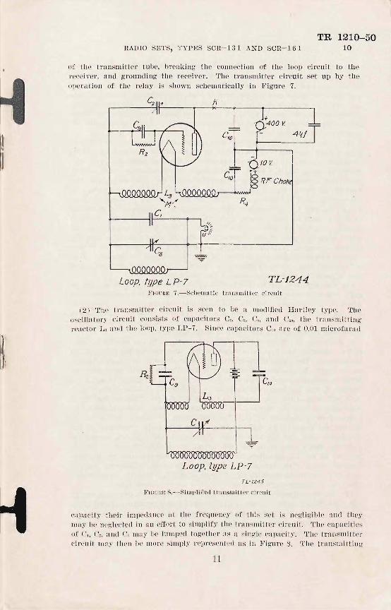
of the trall,'mitte l' tube, breaking the connection of the loop circuit to the receiver , and g rounding the r eceiver. The translll.it'I'cl' circui t set up by the opel'ation of the reIllY is shown schematically in l!' igure 7,
K
Loop, type L P-7 TL-J244 1<'10['1<10 7,-Sciwlllat'i c trAnsmittel' cil'cu i t
(2) Thl' t ransm itte r circlli t is !,;CE'n to be a mod ified Hnl'tley typE'. The o~c il1<1tory cirellit consists of cnpacitors e" e" U" ;'Im1 C,O, thE' ITan>'mitting reudol' L, ' illd the loop, t~'J1e LP- 7, Since capaCitor:; elO nre of 0,01 microfarad
c
Loop, type LP-7
TL-/245
FrcuHI; fl,-Simpl i fied t l'allsm i tter circuit
capacity I'heir impedallcc at the frequcncy of LIli. ' ,et is ncg1igiblc nnd they may be llc~lected ill an efCort to simplify thE' transllI it'tel' ('ircuii'. The capacities of (", C" and C, may be lumped togethor as a ~ingle cnpncil'y, The transmitter circuil' J1I11Y nH'll U(' more si ml)I~1 r epresented as ill Figure 8, The tran!';mittiug
11

TR 1210-50 10 RADIO SJ~TS, TYPES SCn -J 31 AND SCH-161
reactor L" :Illdille l oop, type LP-7, nre in J)nl'a ll cl in I-be oscillatory ci r cuit :lnd since t il e l oop bas fflr Jess iIHluct:ll1ce, ii', witli I-li e Imnpecl ca pacily 0, (letcrl11ines Ibe f requell cy of l11e o~c illat()l'y circuit, 'l'lle purpose of L" i : to provi(jp gri ll ('xcilatioll and plnte l oad for t il e t llbe, it being impraeticable to tnp the loop i u(inctall ce as wonkl be cl one for t ll e nor/l1 :!1 Hartlcy cir cu i t, Allc l'l1:ltiJl~ ]111lte current Jl olI"in~ til rough L" gives thc prOPCl' excitation to thc tube; snnici cnt :llLernalin g" plate cur rent flows t hrough the l oop and capacitor 0 to Illuilltnin tllC osci ll ations of t he loop circuit.
(3) R efer tr) ]<' ig lll'C 7, Thc f uncti ons uf. the various pa r ts are ns follows : 01 is a f ixed capac:il'or which prori(]es thp. mfljol' )Ja r t of t il e capnc ity in the ()scill:l tory cir 'lIi t, Os i s a ntriable ca pn cil'or by menns of wh ich thc osci lla tory circ'uit is IUll cd, C2 is :t f'll1a ll varillul c scrcw clrivcr capacitor whi ch is COI1-nected to t he l oop ciI'cuit by tI le acti on of t li e key r ela y; it compensates tbe loop circlli t [or the l os. of C[[ ll:lCity \\-hic ll is occasi oned II.\' di sconnccti ll g the r eceiver ('ir('lI it from tlie l oop oi l' 'l1 i t ancI thll s mainta ins the frcqlH.'nc~' cn li1)rl1-I io]) 0 (' the loop t lln ing cnpnC'itol" wllPthcr t he sct i s transmitting- or r c('iI"i n~,
C" i s n b.\"-11;_ISS fo r r acIio-fr cq nell c.l' currcnt around the r esisto r & , C,. i s it
by-p: l i';. c<lpaci/'or for ratli o-I'rcquc]) cy current. H, is a grill l e;lk Ihc use of w idell gives th e grid of tlle trnn~IlJitl"ing' I'ubc I- I l(~ propcr negalh'c u ia:; for effici en t opc ration, L" is a 4-tc)'))linal, air-co re coi l Ille turns of w h ich nrc ]ll"oper ly proportion -d to givc grili cxc ita tion and plale l oad for the tubc, U i s a fl;l sh-light J;Jlnp which i s ligh ted h.r C[lITcnt ill thc o.-cill atory cil' 'uit lind LIm!'; offers;] check Oil the operation o f UlC irnllsmil"ter,
(4) Tile Ipft-hand sic!e of the loop is nt ~ro un rl potenti lll w i th rc, pc ,t to radio frequeJJ cy; tld .- llctS to g ive it:t tr an.- lIli t ting anel rcceiv i n~ characteristic which i.- a er:m.1.J i llati on of til(, lloncl ircct i ollnl c IHlrac l- e l"i ~ l ic 01' n \'crl i("a l Ilntellna Ilnd Ih e direC' l"ionul pnttcrn 01' a l oop nl1l'ennn, 'l'l lus the set t r an.-mits :l lld recei ve's wc ll i n all d ircc tion >:, but 1'01' t'xtl'('1l1e distnllr'c ran ge.- t il ' plnnc of the loop .- ll oli ld poill t _ill th e tlirecl:ion or the d istnnt s tr~tion,
b, R ecei li cl',- (l) \\' IWll t il e key i s np, the r pla:v i s i ll the ullnct llnte<1 ('oneli/'i on, conllecting the l oop, cnpaci l ors C, nl1(l G" and transmUting rClictor L" to the r cceiver. '1' lI e circni t of the l'ccl'iver i:-; Ih C' 1l ns ShOW ll ill 111 (' si lilplifi 'Ii drawi JJg in F i gllre 9, Oomparison of Fig-lire 9 with F igure JO wi ll sil o\\' thnt t he l atte r is a fUI'I-1!cr Sillipli fjcation or III' circui t ill whicli 0 I'cplnce: 01 and c." L rClll; lccs La and Ih e loop inli II cI"; I n('c, [llId C" repl;lcrs • and C." l~ rOI1I F i ,~urc
JO it will be seell thai" I'he capac i tor.- c." Or. ancl tile gr id-fil amcn t capacity of I'lle !irst tuhe form the four a rms of a Wll ea tstone brill "e, Tile britl ;.:c may be 1J:JlallC(' cl hy adjustment of Cr. , '1 ' il e l oop circ ll i t i s conplPd 10 1hC' hric!:.;c 1-11 roug"il the capacitor C3. made smnll so as to reduce the i ll teracti on or the JlCteroclY I.I(' luhc :l1Ic! tllc l oop ('i r("uit, \'oll"ag-c: a 'l"O~s C anll L hccH use of illcomi))g" signnl curren t in th e l oop Circuit [I I' ;lpjllied throu;.:1l C;: to I'he :innctiolJ of' Ille ClI C: I[lHcitors, through the upper ell 'ap[I 'Hor 1'0 th(' g-rid HlanlC'n i: circuil; of Ihe heteroc! yne tube, Si ll 'e I-he br idge i s bnluncccl, thcr e i s 11 0 vo l tage <luc to Ihe iucoming signn l acros:; L, alld 00, 'I.'llus Ihe l oop docs not :1f1'CCt th e freq uency 0{ the OSCillator y circu it of Ol e ll ctcr ollyne tuhe,
(2) 'l' ile heter odyne tube i s a simple r egenel'ative tuned gl'id OSCillator, energy being fccl f rom tile plnte ci rcuit ill L , to I;lle OSCilla tor y circuit consisl' ing- of [," ('" and Cu, Sinco the gri d-Ji lament capaCity of the t))he i. c(( llnl 1'0 1'11:11" of Cr.. IHllf of the vol tage acr oss t lJe osci llator y circuit is applied to t he grid-fi lament circuit of t he t llue, F urtllel', sillce tile bridge is bal:lI1cecl, t ll el'o i s no \'olt:l/!c
12

H RADIO SETS, TYPES SOR-13 1 AND SOR-161
TR 1210-50 10
beca use of the 0 cillatol'Y circuit current between the junction of the Cll
capacitors find ground; hencc tbe loop circui t is unaffec ted by the I, etel'odyne oscillatol'Y circuit. The bridgc a rrangement by which loop and beterodyne cil'-
Loop. lypeLP-7 -Y
FIGUnE O,-Seh mnUc ,'peeivcl' ci .'cuit
L
c TL-1247
F.mJR}; 1 a,- Simplifi ed .' e~c il-cl' circuit
cuits a re coupled together Drc\'ents r:1tliation from the locn l oscil la to ry circn it and nlso pl'ev<:'nts the 100J1 circuit from nffecI'ilig tile tuning of I'ile local oscillator. 1.'he loca l OSCillator tuhe :leI's nl so a s n rep;enerntil'C' detector lJecaus(' 1If' the capa('ito l' llIH] grid lenk Co aJ1(] H, in thl' g'rid-filnment ('ircui1. Till' pnl'h J'OI'
dil'pcl' ('111'1'('111' ill 11,1' g'rirl circuil is frolll fila llIen I 1I11'Ollg'iI H3 all(] T" to g' I'id.
13

TR 1210-50 10-11 RADIO SETS, TYPES SCR.-l 3 1 AND SCU-161
(3) If the r eceive r were not carefu ll y shi elded, t il e ope1'>l(ion of the transmitter would pnra lY7.e the 10C'fl l oscillator elete' tor nnel preveut t he method 0'" tuning t ra ll sm itte r anel recei ver whi ch is u, 'ed with t his set,
(4) Heft'l' to Fignre C, T he Iu nctions of (he variou.' parts are as fo llows: The operation or the fo ll owi llg ha s been desc riberl flbove: C" C3, C" Cw, C", e., L" L3, find t he loop, 8, is :111 adjustable Capacitor ; Co which i in pnra llel w it h it is a vil l'iable capncitor for t uning t he oscillato ry Ci rcui t of' the h('te rodyne tube, C" is a capacitor t hrough which gro·und is placecl upon til!' r eceiver whil e ,'elllling so as to l'etluce t he pick-up oe energy by the r ecei,er from the t l'llnsmitter, C7, C., and Co a l'e by-pnss capaCi tors, T is un nutlio-f requency trunsforlJler, type U-D5,
(5) An inCOI11 ing signa l be~1 ts witb th e sigllal of the local oscill ato r and the tube, fl cting a lso as a detector, amplifi es current; of an audio f requency which is the clilIe rence bet\\' en t he freq uencies of t he incoming sign:!l and of the 10C'fl l 0 'c illa(-or, l.'lIe resultant fI\ld io-f l'equency signfll b Ilmplifi e<l by 1'\1'0 stag-es O'f' transforiller coupled :ll1t1io-f'requcuey amplification u, 'ing t ube:, type VT-24, before beillg a pplied to t he hen d .'ets,
TL-1248
F I OU IH~ l1..- Wil'illg Ilill ,l!.I'HJll, t,rpe ON- aD
11. Generator, type GN-35,-The w irin g cliagram of th€' genel'fl tol' is shown in Figul'e 1J, l.'he fi c ld 'Yinding connecl-s flcross lhe low-vollagp winding of the armature [[ud 1)L'ovid : excitation for hot h high and low vo ltnge wiuding:, A radio-frequency, a ir-core ciloke coil is COllllcc l-pd in the posit ive lead of the low voltage and th e high voltage i,' shunted by a cnpacitor C,o, F igure 6; these fllnelion togcther 10 r educe the noise i llterfercncc in (11 (' rec iving re:uHing from commuta to r fict ion , The cord, type CD-103, plugs into I-he 4-point socket; t he co rel is shielded :mll (Jl e shie ld is gr oundecl 11 1- ('ach encl. The yoltage coil of the l'cgnlal or is eonnect-c:d in s('l'i('s wiih tile 23-0 11111 resistor clirce tly acro:s (-he 101l'-vo ltagc wi llcling of I-he genera to r, Thc cOlll ac(or operated by the voHage coil may bp in one of t hrcc llosili ons, aga inst, A, lJehveen A and B,-or aga i ll~1 B, -When I.he 'ontactO I' is 1I gfl inst A, the 20-011111 res istor is sllol'l- d and the field wil1llillg i: eonnccted direcl'ly to the low voltage of the gcn('l'nl-or, Increase of current through the I'egulntor coil due to a ri Sing low voltage pulls the contaeto !' ill to u position in te rm ediate between A and B; ill th is po. ition the short
14

H RADIO SETS, TYPES SCR-1 3 1 AND SCR.-1G l
TR 1210-50 11-12
across f"l1e 20-obm res istor bas been remoyed nnd Ow 20 ohm,' is in series with I he fie ld winding and I be low yoltage. If tile contacl 01' i ~ d)'awil a ll the way OVCl' 10 B. the fie ld windin g- is shorted by being- grounded at both ends and the 20-obm resistor is left across the low vo ltage. The change from one 1'0 a nother of the three po. s ihl e positi ons of Ih<' con lu clor OCtUl'S rapidly and the regulatill:;:' action is exceptiollal ly good .
• 'EC'I'IO N' VI
CARE. AD.Tn;'L'lUEKT, JlI AI:\T'['JilN.,\ NCE. AND HEPATR Pnl'ag-I'apb
Ca rc and adjus l Illelli' of the 8el'__ ________ ____ _________ ________ _____ ____ ____ ____ 12 ~[nlntc llnncc nlld rell,, ;r of Ihe seL ______ ___ ______ ________ _____ ___ ____ ___ __ ____ l~
Tl'ollhles and 1 hei r rclll cdi rs ____ _______ __ ______ ___ ___ _____ __ ___ __ _________ - -___ 14
12. Care and adjustment of the set.-(~. Radio 1'coe-i1;cl' and tl'(/lI slIIitl m', 111M lJ O- 14B (13 0-.1,11) .-(1) Oare.- Thi· p icce of equipment has beeu const ructed to r cquire H minimUIll of Cllre IIl1d al'tentiOI1. It should, howel'cr, recc il'e the same ca reful band ling acco]'(leli to a ll .\' piece of l!r('{' iSion appllratus. Dropp illg and rough b and lin g of Ihe rallio receiver and ITansmiltcr are not a proper pa r t 01' service conditions. Roul'inc care will 'o ns ist in keeping it f ree f rOI11 dust inside aud in in spectillg the spring contacl's between panel-m ounl'cd npPflrMus Hllll apPlll'nlllS mounted in I'Il e oox to see thnt the cOl1hl(:t~ ma ke pos itive COllnectiolls.
(:l) A,djll,Si'lnclil of f1'eqllcncy i ll Ill e ti c/d.-It i.' cle.' irab le that a ll set. opel'fltin g with in II uni t be ca li brated for frequcn(·y . '1' lIi s i. clone b~' adjuslment of t il e poinl er on t Il e rcceil'c )' tu ning di nl. One set ,'hou ld be ~e l ec t'eel as the ~ta lldal'(l /l lld t ll c f req ucllcy of its r eceiver adjusteel {'O 4,360 (5,100) kil ocycles by a w/ll'e llle l 1': lI'ilb the receil'e r luning Im ob heW firm ly, tile pOin te )' of the rc 'eiver din! slJOulLi be lIloved 1'0 Ill c {.360 (5.100 ) kiloc'yc ll' mark. Thi .. • ·et is t hen used (0 ca libra te tile other sl' l s lIy ha vin g the I alldard use the pro(,pclure presc ri bed for a net control stal'ion . 'l'lle olher sets lun e thei r receivers to ;l,C)'O beat "'ilh thc tl'fll1sm ittel' of I'be stn nclHrcl, thc lat ter be iu~. tat 4,360 (5.100 ) kil ocycles. Eacb sel whcn {'uu ed to zer o bent i s cH li brated by holding Ille receiver tuning kllob firllll.f while the poiul'er of the receive r is ~ li cl
arouncl to the 4,360 (5,100) kilocycle marIe The, ets a re then adjusted fOl' fi plcl u ·e.
(3) Reoe iver b(Lloncillg acljll ·I menl.-The capacitor C., Figure 6, is a sl1l all Screw drive!' capacitor access to ",hich fol' ad justment is obtained through I he s )'ew plug :I t t he back of t he a[)para tus box Jl1a rked HECEIVER COM:PE TSATING. '1'0 mlll,e t hi s acljustment, the screw p lug i." )'emOI'etl and the Cilpucitor capacity vHri cl by u. ing a screw (iril'er mude by form iug n tip on a bakeli te rod. The capacitor should be adju sted until t ile r eceiver tunes at both 3,960 (4,370) :1 nd 4,360 (5,]00) kilocy<:lcs against a p reCision wl1l'emetel', This nujus tlll ell t is J11ad e in p roduction and s hould not be necessa ry in the fi eld.
(4) BalM/oint! arijlls lm enl. (a) Thi s ndjustJ11 cn t to the ca pa city Wheatstone bridge is J11ad e by aa
justing' the capn 'il~r of capilcitor Cn. Figure 6. Wh en the bridge i ~ ])I'operl y balan 'ed th e sig-na l hea rd at a l1enr-by set caused by the 10tl1 ! heterodyn e oscill ato r is recl uced to n. minimulIl.When the set is conRirlera bly Ollt of ba l ~ln ce, tuning the loop circui t will cause a click to be hear cl in the hend phones IlS it come,' ill to resonance
15

TR 1210-50 12 l~ADIO SRTS, :rYPES SOR-l3'] AND SOR- I G 1
wil'h thc locn l o,'e illat or fll1l1 flhsol'hs power from it, BalAncing- can not he l)er1'ol'111e(1 ill t'he fi elel nnel should bc nttclllptctl oll l~' by compctent ]JCl' 'onll ' I ha ving t.h e l'equ isil e C(] UiplllCIl t.. ~'lie ~cts w ill be balnncC'd during 1'1'o(l uction a nd should l'cquire litt le balancing t hcrenl't'cr , I II thc .fic ld, h o\\'eYcr, it 'i ~ hi g-hl y desirahl c t'o tryout all availablc tubC's, typc YT-24, in t hc 1 C'ft-h a nel soekct of thc receil'c r lind lI SC t hc re that t'ube which g il'c::; t he hcst signal strcngth when r cceh ' in g ;I wcak ::;igunl unci at thc ,'mllc timc causcs no frequency change wil en the loop i::,; brought into tune, Tbc tube, if ,'0 sc lected, gil'cs a satisJ'acto ry halnnce for operation,
(b) '1'he ba la ncing adjustmcnt, when nccessal'Y alld w hen competent personnel \\'ith WOller e(]uipmellt i s L1\' ailalJl c, is pcrfol'llled as fo ll ow,': RCIl1<l\'e the mcta l scrcw plug nt the bnck of tbc set box, markC'!1 BALANCING. T hen use a screw (I riv l' made f rom a bakelite rod by f'Ol'ln ing a tip Oll it to turn thc cnpacitor a (lj ustin g SCI'(,W, 'I'h ~
pancl must be fi rml y closed, all tubcs in their sockets and the set in It r cech 'in g cOlltli Uoll , Set thc recciYer tunin g a t 4,8GO (:;,]00) ki loeycle,', Conll cct n vacunm tubc \'ollll1etcr cllp<lblc or rca ding-0,05 vo lt nltel'llating current el'f ec ti l' e ac ross the loop te r lllinnl ~,
~'hcn ntlju,t thc loop tuning capa citor fo r maximull1 reading of t he voHll letCl'. },'ow acljnst C. with tile bllkE'l itc scrcw drivcr nnti l minim11m rcndin g of t he \'oHlI1eter is OlJhli nE!tl, illdi cntill g t' II C be,t possible balnncc, 'L'une thc loop t uning capaCitor again to rcsonance wit.1i the locn l o~ci ll ntor lubc n,' illclicntecl b~' the mn x imum r E':iC]ing o f tile \'oltlllctc r :llul u(lju t fu r ther t hc ba l:'Jn 'illg ca pa ci tor ,
( 5 ) T1'CI11MlIU l or cO IJI/JeI180 1i11{j adj-IIRtlll onl.- 'rhh is tbc :ltljn ~tlll cllt o f tllc Cfl pn C' ilor ('" F i .... lll'c G, thc rn p:lcity o f' w lli c l.i rcpJa 'cs that oJ' th l'ccciver when the set is transmitting, T hc acl:i ustment is JI1ntl e lJy r Clllo\'ing tbe ,'crcw plu g JlllI rl(('(1 TRAN~j\[I'l'T]CU CO:\lPENSA'1'ING neal' the tup n t t l.i c rigbt-Iland s i(lc oi' t he apparnt lls box, A scrcw t1rh'c l' mn<lc by fo rming it t ip on II bal,elite l'()(] i s inse r te<l into t'lle h ole amI lI sed to t lll'11 tll c capll c ito r u<lju tit illg screw, 'J' he receivcr 1. ' carefully i'lll1ecl t'o 4,~GO (5,]00) Id locyclc' and the key is 1J('1(1 clow lI ; thc lI<ljUStil/g scr cw is thcli tu rncd unti l 7.cro bcnt bctwecn l' r:lllRllI it'tcl' flllt! receiver 1. rC'f\ched , '1'lJe sc ts w ill hnye thi s ncljn stm en t made duri llg ]11'1)
!luC'tion nll(1 t hc nerc, s i t~7 for fmther a(ljnstnwnt wi ll hc exceptiona l. b, Con omtor, II/PO CN-S5,-('I) Ca r r ,-The gcner fltor is bnilt to J'c(]uirc a
m inimum of ClI re, It is ruggcd hut 'llo11l<l not on tlJat account 1)(' !<uh.i C'c te tl to lI n r(1 usage, 'rhe s haHs rUIl in ball bcarings; thc,'e Inst do not reqllirc lnhr iclition bu t tile hall s and race mll ,'t hc kept greascll to prevent rus t ing, BvcI' Y six montll s til e bea r ing, should he gr0asc(l wi t h V:lSC' I'iIlC or li ght IIlO tO l' gTease; exccssive grcasing will l'esult 'i n generator t rouble as surely as i'ailnre to grease the beal''i llg:' , To greasc th c bC:1l.'ings, r emove t he fivc sc rews 11 0111-jng t'li c p rojection on ti le r ight of' t he gell erato r !lou sing ; t he pr ojection may then he removecl and t hree ball bea rings w ill he found, On t he lE'ft-h an!l s icle oj' t he generator a re two dill1 ollli- ,' il npecl plnt es, 1':1 'h hel ll to t he hou~ing
by two ;:;('r l'w;:;; remov illg the!<e platc,.; (f ivcs ncccss to th e othe r bf'a l'illgs or lhe gell eratol', one bl'nCfltll each pllll'e,
(2) A(/jll,~flllenl ,-This g-cnc l'Htor i s 11 Hccl with rll(lio ;:;(' Is, t'ypes SClt- l:1l , S(Jlt-lf>1 , fWlt- 171 , :llIll f)t'R-Hi8, 1<'01' th(' l'ndi o Sl' t , t,\'pe ~Cl t- J(;:l, l ll e gC ll cmtol' wi ll llrovi de 8 volls :I11 l1 3!iO volts ; a s I'P('u ivcd I'I'0m t'li c 1II:Jlluf'ac-
lG

RADIO SETS, l"'YPES S R-131 AN D SCR-161 TR 1210-50
12-15
t llrcr it \Yil l bc aclju , led to giye these YoltHge~, Fu r llie I'emainin g ~c t,.; it 1.' readj u,'teel to 10 volts and 400 Yolt:; this I'l'adjllstmcnt is made before is: uing t ll c generator \Yith t he set, The Il ame plale used with t he "eneratol' has lwo s tamped sides and that side : hould be uppermost which I cal': the \'oltage I'ati ng fo r the Rct with which the gencratur is is 'ueel. The ratin" on t ll c namc plate shoulcl be chcckcd to see that it agrees wilh t Il e set J'eguireIlI cnts, H fo uncl to be wrong, the voltages Illay bc all justed to the proper \'alues as fo ll ows: ~'hc gellerator is connected to the ,'et which is in a tr>\u:;lIIitting condition and the gencra to r is turned at norlllal speecl, A voltmet'('l', or seri cs of \'olt mctcrs of the sam tY[lC, is cnnnc<;tC'el to prO!lg ' :3 :Iud 4 fJj' t ile CUi'll, typc CD- lO:3, at the generator em!. The tension on the arlllature screw, mHrked C in F igure 11, is tllen adju'tcd until t he Yo!tage read is 400 Yolts wit Ii l hc t ra nswitting kcy depressed, '.rurn in" the armature screw in a clockwise direct ion incrcases tile yollage; tUl'Jlin" it 'ounterclockwi se lkcreasl's llle Yol bl;.!;e, Access lo the armature screw for thi s adju stment is uhtained by removi ng the foul' screw ' on the top of the generator Jlou sing and li fti ng or[ the top,
13. Maintenance and r epair of the set.-The field lIIainlenan ce of this :et wil l consi:t in g('Il ('r al of rflutine l'lI re given I'Il e set a lld of fmch minor r epairs a ~ nre practical ill t he fi eld, The IlClju stmcn t:~ IIt'('e:;sary and L1l e trou!)l!'s \l'hieh may be C'xpccted fl rc covered in paragraphs J:" a nd 14, r cspecli \·pl,\' ,
14. Troubles and their remedies.-Pract ically a ll uf the t roubl es eXl)eri enC0l\ with thi ~ set w ill be due to mechani cal CH USC~. If the panel is not completely doscd. the spring eont'll(:t .. in t he Hppa ratus box \I'ill not make good conl:H.: t 1111(1 the Sf't ma y fa il to function. In C:lse of receiYer fa ilure, the cuntacts at t he batte ry binding posts .. houlcl bl) cheeked, then the 'o udi t ion of the balteri es th em:elve:. Ocea, ional fau lty contact may be had in the t ube socket~ because of dir ty pron;.!;s on Lhe tubes or beeau.'e the set has not been kept free f rom dust and gri t. The hend phones .. hould not be left plugged intu th e jacks during tranSl)OrtaLion because some head sets have a ground from their windings to the r eceiver case; thi case mil~· come into contact with the f rame of the set and provide a ci rcuit for the B batterie', g l'adually running them down.
SECTION VII
LIST OF PARTS Puragraph
Lis t of PQ 1'\" _________ ___ _____ _ _______ ___________ ____ __ ___ __ -- - ---------- -___ 15
15. List of parts.-The fo llowing are the component parts of lhe radio set, type SCR- l:31 (SUB 161 ) :
1 bag. type BG-49, for loop, "ene.·ator legs and cnll1ks. 1 bag, type BG-50, for, pare batteri 's anel tubes, corel , type CD-103, and
mes, age book., log sheets, etc. J case, type CS-41, for generator, type GN-35. 4 bat teries, type BA-2, 2 in use, 2 spare. 6 batte ri e', type BA-2:3, 3 in use, 3 spare. 1 cord, type CD- 103. 2 cranks, type GC-2, for generator, type GN-35. 1 Gauge, type TL-127. 1 generator, type GN-35. 2 !lead sets, type P-11 or P- 12. 2 lamps, type LM-4, 1 in usc, 1 spure.
17