msp430 launchpad · web viewi think the setting of 12 accomplished something of the same...
TRANSCRIPT

MSP430 LaunchpadDon Bindner<[email protected]>Table of Contents
1. Prepping for the MSP430
2. Out of the box
3. Blinking lights number 2
4. Pushbutton fun
5. More pretty lights
6. Community Coding Style
7. Button triggered interrupts
8. Hello World revisited8.1. Internal watchdog timer8.2. External timer crystals
9. Blinking lights revisited9.1. Using internal timer9.2. Using external crystal
10. Pulse Width Modulation10.1. Sleeping LED10.2. Which pins do PWM?
11. Talking to MSP430 via Launchpad USB interface
12. Yet another Hello World
13. Serial communication 1
14. Serial communication 2

15. Adding button debounce
16. A Uart receiver
17. Send and Receive
18. Send and Receive 2
19. Increasing the clock speed
20. Reading off calibration values
21. A more robust calibration program
22. Dissecting the TI temperature demo
23. Bit-bang I2C interface for Newhaven LCD panel
24. Bit-bang SPI interface for ktm-s1201 LCD panel
25. Morse Code on the MSP430
26. Recovering a FRAM Experimenter’s Board
27. Basic burglar alarm
1. Prepping for the MSP430
It took about a week for my MSP430 Launchpad to arrive
after I ordered it from TI. That gave me time to make sure
my Linux system would work with the hardware. The udev
system needs to be made aware of the Launchpad, so I
added this file: /etc/udev/rules.d/46-TI_launchpad.rules on
my Ubuntu Lucid system:
ATTRS{idVendor}=="0451", ATTRS{idProduct}=="f430", MODE="660", GROUP="plugdev"

ATTRS{idVendor}=="0451", ATTRS{idProduct}=="f432", MODE="660", GROUP="plugdev"
A quick restart udev as root, and my system was ready to
recognize the Launchpad.
I also made sure that my personal user account was in
the plugdev group in /etc/group, so I’d have read and write
access to /dev/ttyACM0 when the board is plugged in. It
was already.
For compiling, I installed mspgcc4
from http://sourceforge.net/projects/mspgcc4/files/ . It takes
a long time to build mspgcc4, but otherwise the install was
pretty painless.
I learned that I’d also want mspdebug for communicating
with the board and installing newly compiled programs. So
I built that from the source
athttp://sourceforge.net/projects/mspdebug/files/ . It also
installed smoothly.
Then it was just a matter of waiting for my board to arrive.
2. Out of the box
March 11, 2011. My Launchpad came today. I’d watched
the demo video, so naturally I tried the experiment where
you rub on the chip to make it warmer. But what I really
wanted to do is write some of my own code and program it
to a chip. So I swapped out the pre-recorded chip for the
msp430g2211 that comes in the non-static envelope. I went
off to find a Hello World program.
As I understand it, in the world of microcontrollers, Hello World programs blink and LED on and off. Well, conveniently, the Launchpad has two LEDs built into the support board. One is on pin 0 and the other is on pin 6.
I’m planning to do my development on my Linux laptop with mspgcc4, so I set off to find a simple C program to compile and send to the chip.
After a bit, I ran across something similar, but not quite
exactly like this.
#include <io.h>
#define pin6mask (0x01 << 6)
int main(void) { /* Hold the watchdog timer so it doesn't reset our chip */ WDTCTL = WDTPW + WDTHOLD;
/* Configure all pins on port 1 as output pins */ P1DIR = 0xff;
/* Set pin 6 high. Basically, this command sets any combination * of the pins on port 1 high. Pin 0 is 2^0, pin 1 is 2^2, etc. * Values can be binary or'd together. Other pins are low. */ P1OUT = pin6mask;
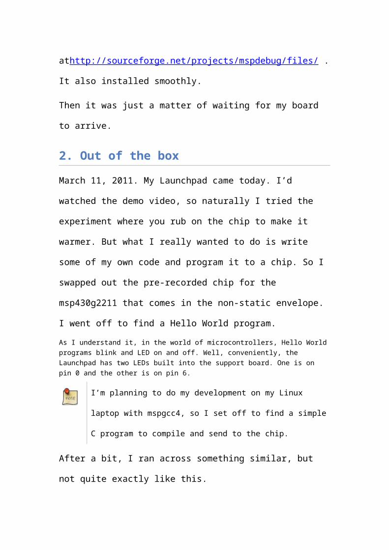
/* infinite loop */ for( ; ; ) { /* The following two lines implement a very crude delay loop. * The actual length of the delay can vary significantly. * This approach may not work with all compilers.

*/ volatile int i; for( i = 0; i < 20000; i++ );
/* Toggle the state of pin 6 on port 1 by exclusive or'ing with the mask that represents that pin. */ P1OUT = P1OUT ^ pin6mask; }}
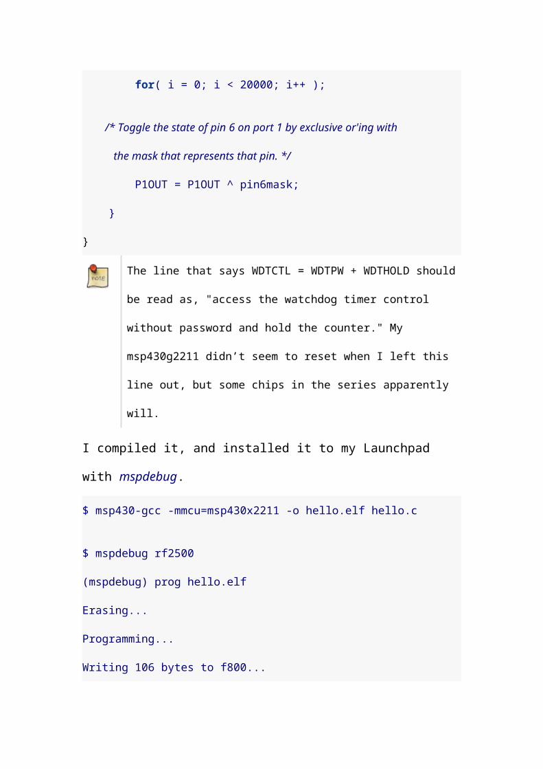
The line that says WDTCTL = WDTPW + WDTHOLD should be read as, "access the watchdog timer control without password and hold the counter." My msp430g2211 didn’t seem to reset when I left this line out, but some chips in the series apparently will.
I compiled it, and installed it to my Launchpad
with mspdebug.
$ msp430-gcc -mmcu=msp430x2211 -o hello.elf hello.c
$ mspdebug rf2500(mspdebug) prog hello.elfErasing...Programming...Writing 106 bytes to f800...Writing 32 bytes to ffe0...(mspdebug) runRunning. Press Ctrl+C to interrupt...^C...(mspdebug) ^D
Blink. Blink. Blink. Hello, world!
3. Blinking lights number 2
There are two LEDs on the board, so lets make a small
change to blink both of them! While, we’re making changes,
we’ll try to be a little more subtle. This time we’ll only set
the pins we want to actually use as output pins.
#include <io.h>
#define pin0mask (0x01 << 0)#define pin6mask (0x01 << 6)
int main(void) { /* Hold the watchdog timer so it doesn't reset our chip */ WDTCTL = WDTPW + WDTHOLD;
/* Configure pins 0,6 on port 1 as output pins */ P1DIR = pin0mask | pin6mask;
/* Set pin 6 high. Basically, this command sets any combination * of the pins on port 1 high. Pin 0 is 2^0, pin 1 is 2^2, etc. * Values can be binary or'd together. Other pins are low. */ P1OUT = pin6mask;
/* infinite loop */ for( ; ; ) { /* The following two lines implement a very crude delay loop. * The actual length of the delay can vary significantly. * This approach may not work with all compilers. */ volatile int i; for( i = 0; i < 20000; i++ );
/* Toggle the state of pins 0,6 on port 1 by exclusive or'ing with the mask that represents those pins. */ P1OUT = P1OUT ^ (pin0mask | pin6mask); }}
It’s clear that we’re going to be compiling and installing
object code repeatedly. This can be done in a single step by
a command similar to this:

$ msp430-gcc -mmcu=msp430x2211 -o hello.elf hello.c && mspdebug rf2500 'prog hello.elf'
The way to think of this command is, "Compile the source,
and, if successful, run mspdebug to program the object
code to the Launchpad."
4. Pushbutton fun
The Launchpad board has two pushbuttons. One is hooked
to reset, so we might not be able to access that (I don’t
know yet). But the other one is hooked to pin 3, and we can
definitely check that. It turns out that pin 3 is high when the
button is not pushed and goes low when we press it.
We can use that to change the behavior of our lights. Let’s
blink only the red light when the button is down and blink
both lights (not necessarily alternately as you’ll see) when
the button is up.
#include <io.h>
#define pin0mask (0x01 << 0)#define pin3mask (0x01 << 3)#define pin6mask (0x01 << 6)
int main(void) { /* Hold the watchdog timer so it doesn't reset our chip */ WDTCTL = WDTPW + WDTHOLD;
/* Configure pins 0,6 on port 1 as output pins */ P1DIR = pin0mask | pin6mask;

/* Set pin 6 high. Basically, this command sets any combination * of the pins on port 1 high. Pin 0 is 2^0, pin 1 is 2^2, etc. * Values can be binary or'd together. Other pins are low. */ P1OUT = pin6mask;
/* infinite loop */ for( ; ; ) { /* The following two lines implement a very crude delay loop. * The actual length of the delay can vary significantly. * This approach may not work with all compilers. */ volatile int i; for( i = 0; i < 20000; i++ );
/* Switch 2 is connected to pin 3. If it is low, then change the * blinking behavior. Sometimes we blink both LEDs, sometimes only * the red LED. */ if(( P1IN & pin3mask ) == 0 ) { /* Toggle just pin 0. */ P1OUT ^= pin0mask; } else { /* Toggle both pin 0 and pin 6 */ P1OUT ^= pin0mask|pin6mask; } }}
When you press switch 2 (which is connected to pin 3) the
green LED will quit changing state, and only the red LED
will flash. When you release the button, both will flash again
(though whether they alternate or not depends on the
timing of your button release).
5. More pretty lights

How about a program that knows severals blink patterns?
This program knows "red only" and "green only" and "both
together" and "both alternately." For your enjoyment:
#include <io.h>
#define pin0mask (0x01 << 0)#define pin3mask (0x01 << 3)#define pin6mask (0x01 << 6)
int main(void) { /* Hold the watchdog timer so it doesn't reset our chip */ WDTCTL = WDTPW + WDTHOLD;
/* Configure pins 0,6 on port 1 as output pins */ P1DIR = pin0mask | pin6mask;
/* a flag to tell us when we've handled a button event */ int buttonPushed = 0;
/* we'll toggle between different modes */ int blinkMode = 0;
/* which lights we need to blink -- start red only */ int blinkMask = pin0mask;
/* make sure green (pin 6) is turned off */ P1OUT &= ~pin6mask;
/* infinite loop */ for( ; ; ) { /* The following two lines implement a very crude delay loop. * The actual length of the delay can vary significantly. * This approach may not work with all compilers. */ volatile int i; for( i = 0; i < 20000; i++ );
/* Switch 2 is connected to pin 3. If it is low, then change the * blinking behavior (unless it we have handled the press already)

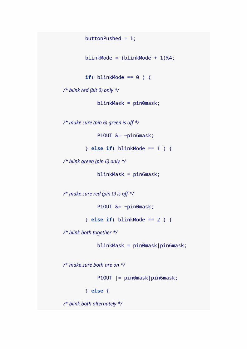
*/ if(( P1IN & pin3mask ) == 0 ) { if( !buttonPushed ) { /* remember so we don't try to handle this press again */ buttonPushed = 1;
blinkMode = (blinkMode + 1)%4;
if( blinkMode == 0 ) { /* blink red (bit 0) only */ blinkMask = pin0mask;
/* make sure (pin 6) green is off */ P1OUT &= ~pin6mask; } else if( blinkMode == 1 ) { /* blink green (pin 6) only */ blinkMask = pin6mask;
/* make sure red (pin 0) is off */ P1OUT &= ~pin0mask; } else if( blinkMode == 2 ) { /* blink both together */ blinkMask = pin0mask|pin6mask;
/* make sure both are on */ P1OUT |= pin0mask|pin6mask; } else { /* blink both alternately */ blinkMask = pin0mask|pin6mask;
/* make sure red is off and green is on */ P1OUT &= ~pin0mask; P1OUT |= pin6mask; } } } else { buttonPushed = 0; }
P1OUT ^= blinkMask; }}

You might notice that it misses some key presses if you are
very quick. That’s because it won’t notice a key press (or a
key release) during the delay loop. This program might be
improved a bit by putting the key detection into the loop.
The next version does just that.
#include <io.h>
#define pin0mask (0x01 << 0)#define pin3mask (0x01 << 3)#define pin6mask (0x01 << 6)
int main(void) { /* Hold the watchdog timer so it doesn't reset our chip */ WDTCTL = WDTPW + WDTHOLD;
/* Configure pins 0,6 on port 1 as output pins */ P1DIR = pin0mask | pin6mask;
/* a flag to tell us when we've handled a button event */ int buttonPushed = 0;
/* we'll toggle between different modes */ int blinkMode = 0;
/* which lights we need to blink -- start red only */ int blinkMask = pin0mask;
/* make sure green (pin 6) is turned off */ P1OUT &= ~pin6mask;
/* infinite loop */ for( ; ; ) { int j; /* delay while watching for button presses */ for( j = 0; j < 100; j++ ) { /* The following two lines implement a very crude delay loop. * The actual length of the delay can vary significantly. * This approach may not work with all compilers.

*/ volatile int i; for( i = 0; i < 200; i++ );
/* Switch 2 is connected to pin 3. If it is low, then change the * blinking behavior (unless it we have handled the press already) */ if(( P1IN & pin3mask ) == 0 ) { if( !buttonPushed ) { /* remember so we don't try to handle this press again */ buttonPushed = 1;
blinkMode = (blinkMode + 1)%4;
if( blinkMode == 0 ) { /* blink red (bit 0) only */ blinkMask = pin0mask;
/* make sure green (pin 6) is off */ P1OUT &= ~pin6mask; } else if( blinkMode == 1 ) { /* blink green (pin 6) only */ blinkMask = pin6mask;
/* make sure red (pin 0) is off */ P1OUT &= ~pin0mask; } else if( blinkMode == 2 ) { /* blink both together */ blinkMask = pin0mask|pin6mask;
/* make sure both are on */ P1OUT |= pin0mask|pin6mask; } else { /* blink both alternately */ blinkMask = pin0mask|pin6mask;
/* make sure red is off and green is on */ P1OUT &= ~pin0mask; P1OUT |= pin6mask; } }

} else { buttonPushed = 0; } }
/* blink the lights */ P1OUT ^= blinkMask; }}
6. Community Coding Style
If you read much code written by the MSP430 community,
you’ll notice a couple of differences from the code I have
written. Two things in particular stand out to me. Where I
have use names for constants like pin0mask, most code will
use pre-defined constants, like BIT0.
The other difference is that where I have used #include
<io.h>, other source files will often include a header file for
the specific version of the MSP430 microcontroller they are
targeting. Since I’m currently writing for the msp430g2211,
I could have written #include <msp430g2211.h>.
Another subtle difference is that rather than using or to
combine bitmasks, most of the community code uses plus.
For example, where I might have been inclined to write BIT0
| BIT6, you will instead see BIT0 + BIT6. Since the bitmasks
are non-overlapping binary numbers, it really doesn’t make
any difference.
With these changes, our most recent program would look
like:
#include <msp430g2211.h>
int main(void) { /* Clear and hold the watchdog timer so it doesn't reset our chip */ WDTCTL = WDTPW + WDTHOLD;
/* Configure pins 0,6 on port 1 as output pins */ P1DIR = BIT0 + BIT6;
/* a flag to tell us when we've handled a button event */ int buttonPushed = 0;
/* we'll toggle between different modes */ int blinkMode = 0;
/* which lights we need to blink -- start red only */ int blinkMask = BIT0;
/* make sure green (pin 6) is turned off */ P1OUT &= ~BIT6;
/* infinite loop */ for( ; ; ) { int j; /* delay while watching for button presses */ for( j = 0; j < 100; j++ ) { /* The following two lines implement a very crude delay loop. * The actual length of the delay can vary significantly. * This approach may not work with all compilers. */ volatile int i; for( i = 0; i < 200; i++ );

/* Switch 1 is connected to pin 3. If it is low, then change the * blinking behavior (unless it we have handled the press already) */ if(( P1IN & BIT3 ) == 0 ) { if( !buttonPushed ) { /* remember so we don't try to handle this press again */ buttonPushed = 1;
blinkMode = (blinkMode + 1)%4;
if( blinkMode == 0 ) { /* blink red (bit 0) only */ blinkMask = BIT0;
/* make sure green (pin 6) is off */ P1OUT &= ~BIT6; } else if( blinkMode == 1 ) { /* blink green (pin 6) only */ blinkMask = BIT6;
/* make sure red (pin 0) is off */ P1OUT &= ~BIT0; } else if( blinkMode == 2 ) { /* blink both together */ blinkMask = BIT0 + BIT6;
/* make sure both are on */ P1OUT |= BIT0 + BIT6; } else { /* blink both alternately */ blinkMask = BIT0 + BIT6;
/* make sure red is off and green is on */ P1OUT &= ~BIT0; P1OUT |= BIT6; } } } else { buttonPushed = 0; } }

/* blink the lights */ P1OUT ^= blinkMask; }}
Since the proper microcontroller is specified in the source
code, it is no longer necessary to specify it during the
compile step. To build this code, we can simply do:
$ msp430-gcc -o hello.elf hello.c
This builds a program that is ready to be programmed to
the chip. If we want to build the binary and program the
chip in one step, we can use:
$ msp430-gcc -o hello.elf hello.c && mspdebug rf2500 'prog hello.elf'
People don’t always agree on what makes some code
simpler or easier to understand than other code. As a
beginner, I found that being explicit about the idea of
bitmasks in my variable names felt easier. In general,
though, I think it makes sense to adopt the conventions of
the community around you. To that end, it seems sensible
to:
1. Use #import <io.h> when developing programs when
you have no specific microcontroller in mind (like

tutorials?), and import the relevant header file when
targeting a particular chip.
2. Use the standard names already available to you for
bitmasks and important constants, because that is
what people are accustomed to seeing.
3. Use + to combine bitmasks.
You can discover the names of the relevant header files
where you installed your compiler. For example, I installed
in /opt/msp430-gcc-4.4.5, and this is a list of the different
header files:
$ ls $ ls /opt/msp430-gcc-4.4.5/msp430/include/bits/ msp430f148.h msp430f437.h msp430f5514.h msp430p337.hbyteswap.h msp430f1491.h msp430f438.h msp430f5515.h msp430x09x.hcc430f5133.h msp430f149.h msp430f439.h msp430f5517.h msp430x11x1.hcc430f5135.h msp430f155.h msp430f447.h msp430f5519.h msp430x11x2.hcc430f5137.h msp430f156.h msp430f4481.h msp430f5521.h msp430x11x.hcc430f6125.h msp430f157.h msp430f448.h msp430f5522.h msp430x12x2.hcc430f6126.h msp430f1610.h msp430f4491.h msp430f5524.h msp430x12x.hcc430f6127.h msp430f1611.h msp430f449.h msp430f5525.h msp430x13x1.hcc430f6135.h msp430f1612.h msp430f46161.h msp430f5526.h msp430x13x.hcc430f6137.h msp430f167.h msp430f4616.h msp430f5527.h msp430x14x1.h

cc430x513x.h msp430f168.h msp430f46171.h msp430f5528.h msp430x14x.hcc430x612x.h msp430f169.h msp430f4617.h msp430f5529.h msp430x15x.hcc430x613x.h msp430f2001.h msp430f46181.h msp430f5630.h msp430x16x.hctype.h msp430f2002.h msp430f4618.h msp430f5631.h msp430x20x1.hdebug.h msp430f2003.h msp430f46191.h msp430f5632.h msp430x20x2.hendian.h msp430f2011.h msp430f4619.h msp430f5633.h msp430x20x3.herrno.h msp430f2012.h msp430f47126.h msp430f5634.h msp430x21x1.hin430.h msp430f2013.h msp430f47127.h msp430f5635.h msp430x21x2.hinttypes.h msp430f2101.h msp430f47163.h msp430f5636.h msp430x22x2.hio.h msp430f2111.h msp430f47166.h msp430f5637.h msp430x22x4.hiomacros.h msp430f2112.h msp430f47167.h msp430f5638.h msp430x23x0.hisr_compat.h msp430f2121.h msp430f47173.h msp430f6630.h msp430x23x.hlimits.h msp430f2122.h msp430f47176.h msp430f6631.h msp430x241x.hmath.h msp430f2131.h msp430f47177.h msp430f6632.h msp430x24x1.hmsp430c091.h msp430f2132.h msp430f47183.h msp430f6633.h msp430x24x.hmsp430c092.h msp430f2232.h msp430f47186.h msp430f6634.h msp430x26x.hmsp430c1111.h msp430f2234.h msp430f47187.h msp430f6635.h msp430x31x.hmsp430c111.h msp430f2252.h msp430f47193.h msp430f6636.h msp430x32x.hmsp430c1121.h msp430f2254.h msp430f47196.h msp430f6637.h msp430x33x.hmsp430c112.h msp430f2272.h msp430f47197.h msp430f6638.h msp430x415.hmsp430c1331.h msp430f2274.h msp430f477.h msp430fe4232.h msp430x417.hmsp430c1351.h msp430f2330.h msp430f4783.h msp430fe423a.h msp430x41x2.h

msp430c311s.h msp430f233.h msp430f4784.h msp430fe423.h msp430x41x.hmsp430c312.h msp430f2350.h msp430f478.h msp430fe4242.h msp430x42x0.hmsp430c313.h msp430f235.h msp430f4793.h msp430fe4252.h msp430x42x.hmsp430c314.h msp430f2370.h msp430f4794.h msp430fe425a.h msp430x43x1.hmsp430c315.h msp430f2410.h msp430f479.h msp430fe425.h msp430x43x.hmsp430c323.h msp430f2416.h msp430f5131.h msp430fe4272.h msp430x44x1.hmsp430c325.h msp430f2417.h msp430f5132.h msp430fe427a.h msp430x44x.hmsp430c336.h msp430f2418.h msp430f5151.h msp430fe427.h msp430x461x1.hmsp430c337.h msp430f2419.h msp430f5152.h msp430fg4250.h msp430x46x.hmsp430c412.h msp430f2471.h msp430f5171.h msp430fg4260.h msp430x471x3.hmsp430c413.h msp430f247.h msp430f5172.h msp430fg4270.h msp430x471x6.hmsp430cg4616.h msp430f2481.h msp430f5304.h msp430fg437.h msp430x471x7.hmsp430cg4617.h msp430f248.h msp430f5308.h msp430fg438.h msp430x47x3.hmsp430cg4618.h msp430f2491.h msp430f5309.h msp430fg439.h msp430x47x4.hmsp430cg4619.h msp430f249.h msp430f5310.h msp430fg4616.h msp430x47x.hmsp430e112.h msp430f2616.h msp430f5418a.h msp430fg4617.h msp430x54xa.hmsp430e313.h msp430f2617.h msp430f5418.h msp430fg4618.h msp430x54x.hmsp430e315.h msp430f2618.h msp430f5419a.h msp430fg4619.h msp430x551x.hmsp430e325.h msp430f2619.h msp430f5419.h msp430fg477.h msp430x552x.hmsp430e337.h msp430f412.h msp430f5435a.h msp430fg478.h msp430xe42x2.hmsp430f1101a.h msp430f4132.h msp430f5435.h msp430fg479.h msp430xe42xa.hmsp430f1101.h msp430f413.h msp430f5436a.h msp430fw423.h msp430xe42x.h

msp430f110.h msp430f4152.h msp430f5436.h msp430fw425.h msp430xg42x0.hmsp430f1111a.h msp430f415.h msp430f5437a.h msp430fw427.h msp430xg43x.hmsp430f1111.h msp430f417.h msp430f5437.h msp430g2001.h msp430xg46x.hmsp430f1121a.h msp430f423a.h msp430f5438a.h msp430g2101.h msp430xg47x.hmsp430f1121.h msp430f423.h msp430f5438.h msp430g2111.h msp430xw42x.hmsp430f1122.h msp430f4250.h msp430f5500.h msp430g2121.h setjmp.hmsp430f112.h msp430f425a.h msp430f5501.h msp430g2131.h signal.hmsp430f1132.h msp430f425.h msp430f5502.h msp430g2201.h stdint.hmsp430f1222.h msp430f4260.h msp430f5503.h msp430g2211.h stdio.hmsp430f122.h msp430f4270.h msp430f5504.h msp430g2221.h stdlib.hmsp430f1232.h msp430f427a.h msp430f5505.h msp430g2231.h string.hmsp430f123.h msp430f427.h msp430f5506.h msp430l092.h sys/msp430f133.h msp430f4351.h msp430f5507.h msp430p112.h xms430f5438.hmsp430f135.h msp430f435.h msp430f5508.h msp430p313.hmsp430f1471.h msp430f4361.h msp430f5509.h msp430p315.hmsp430f147.h msp430f436.h msp430f5510.h msp430p315s.hmsp430f1481.h msp430f4371.h msp430f5513.h msp430p325.h
This is how I discovered that the correct include file would
be msp430g2211.h. To see the contents of this header file (to
learn, for example, the names of important constants), I
used:
$ less /opt/msp430-gcc-4.4.5/msp430/include/msp430g2211.h
7. Button triggered interrupts

I don’t entirely know what I’m doing with regard to
interrupt programming on the MSP430 yet, but I have
cobbled together a working program based on some demo
code (translating it so it will compile with mspgcc4). It
toggles the LEDs off and on when you press switch 2.
/* Adapted from Aldo Briano's demo code */#include <msp430g2211.h>
#define RED_LED BIT0#define GRN_LED BIT6#define BUTTON BIT3
int main(void){ /* Stop the watchdog timer so it doesn't reset our chip */ WDTCTL = WDTPW + WDTHOLD;
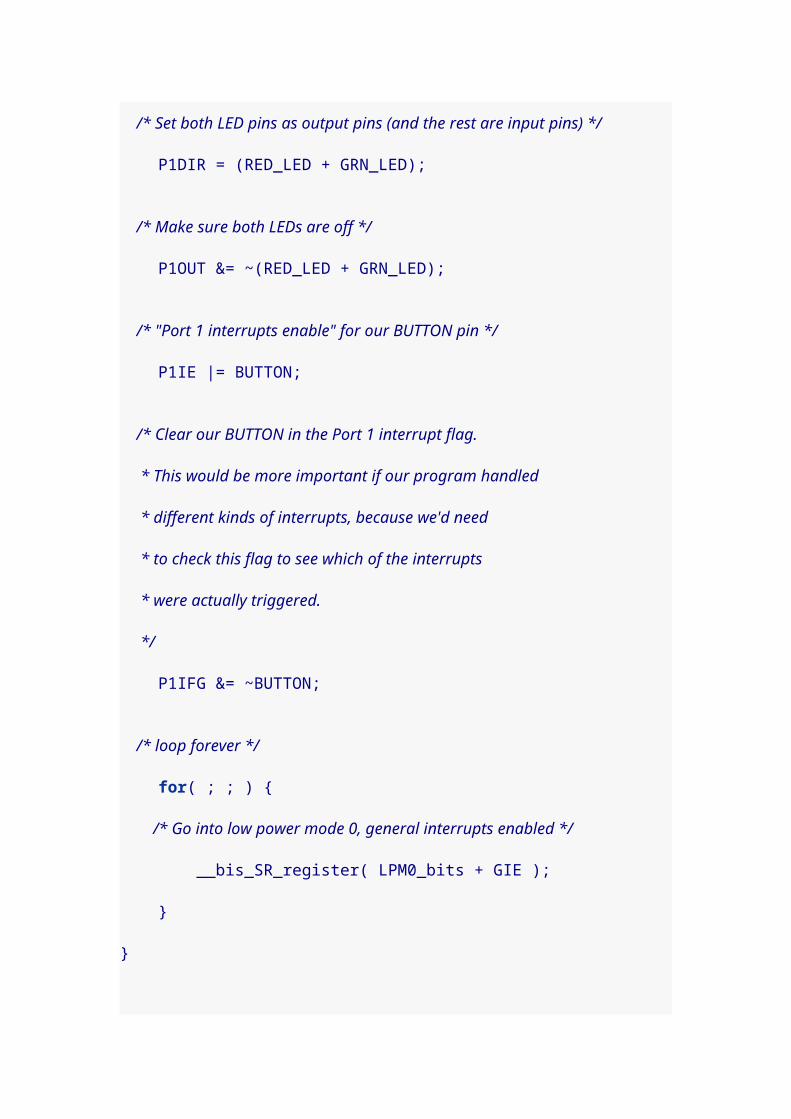
/* Set both LED pins as output pins (and the rest are input pins) */ P1DIR = (RED_LED + GRN_LED);
/* Make sure both LEDs are off */ P1OUT &= ~(RED_LED + GRN_LED);
/* "Port 1 interrupts enable" for our BUTTON pin */ P1IE |= BUTTON;
/* Clear our BUTTON in the Port 1 interrupt flag. * This would be more important if our program handled * different kinds of interrupts, because we'd need * to check this flag to see which of the interrupts * were actually triggered. */ P1IFG &= ~BUTTON;
/* loop forever */ for( ; ; ) { /* Go into low power mode 0, general interrupts enabled */ __bis_SR_register( LPM0_bits + GIE );

}}
/* Port 1 interrupt service routine. First, this prototype tells * the compiler that the function handles interrupts for * Port 1. Then the function follows. */void Port_1 (void) __attribute__((interrupt(PORT1_VECTOR)));void Port_1(void){ /* Toggle both LEDs by xoring with their bitmasks */ P1OUT ^= (RED_LED + GRN_LED);
/* Clear the interrupt flag */ P1IFG &= ~BUTTON; // P1.3 IFG cleared
/* Uncomment the next line if you want button releases also to trigger. * That is, we change the interrupt edge, and Hi-to-Low will * trigger the next interrupt. */ // P1IES ^= BUTTON;
/* This line is still magic to me. I think it exits low power mode 0 * so the main program can resume running. */ __bic_SR_register_on_exit( LPM0_bits );}
8. Hello World revisited
8.1. Internal watchdog timer
I’ve always felt that the original Hello World was sort of
weak. It worked, and managed to blink the LED
succussfully, but I knew it wasn’t the "right" approach. The

right approach would have used the Watchdog Timer to
trigger the blinks.
I eventually found some code I think I understand, and I
have a new Hello World for the MSP430.
#include <msp430g2211.h>
#define RED_LED BIT0
unsigned int wdtCounter = 0;
void main(void){ /* Set watchdog timer interval to 32ms */ WDTCTL = WDT_MDLY_32;
/* "Interrupt enable 1" for the Watchdog Timer interrupt */ IE1 |= WDTIE;
/* Set the LED pin as an output pin */ P1DIR |= RED_LED;
/* Turn on LED pin */ P1OUT |= RED_LED;
/* Go into low power mode 0, general interrupts enabled */ __bis_SR_register( LPM0_bits + GIE );
/* Do nothing...forever */ for( ; ; ) { }}
/* Watchdog Timer interrupt service routine. The function prototype * tells the compiler that this will service the Watchdog Timer, and * then the function follows. */void watchdog_timer(void) __attribute__((interrupt(WDT_VECTOR)));void watchdog_timer(void){

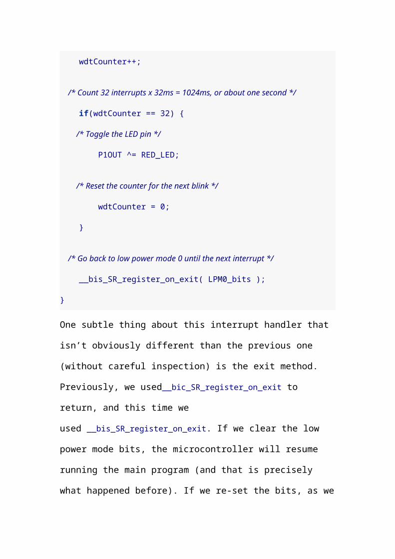
wdtCounter++;
/* Count 32 interrupts x 32ms = 1024ms, or about one second */ if(wdtCounter == 32) { /* Toggle the LED pin */ P1OUT ^= RED_LED;
/* Reset the counter for the next blink */ wdtCounter = 0; }
/* Go back to low power mode 0 until the next interrupt */ __bis_SR_register_on_exit( LPM0_bits );}
One subtle thing about this interrupt handler that isn’t
obviously different than the previous one (without careful
inspection) is the exit method. Previously, we
used__bic_SR_register_on_exit to return, and this time we
used __bis_SR_register_on_exit. If we clear the low power mode
bits, the microcontroller will resume running the main
program (and that is precisely what happened before). If we
re-set the bits, as we did in this example, the
microcontroller will go back to sleep when the handler
returns.
In truth, we didn’t need to do this at all. The default
behavior when exiting an interrupt handler is to set the
Status Register back to the state it had before the interrupt
was triggered. Since the chip was asleep before the button

interrupt occurred, it will go back to sleep if we just exit.
We can remove the __bis_SR_register_on_exit line and it will
work exactly the same way.
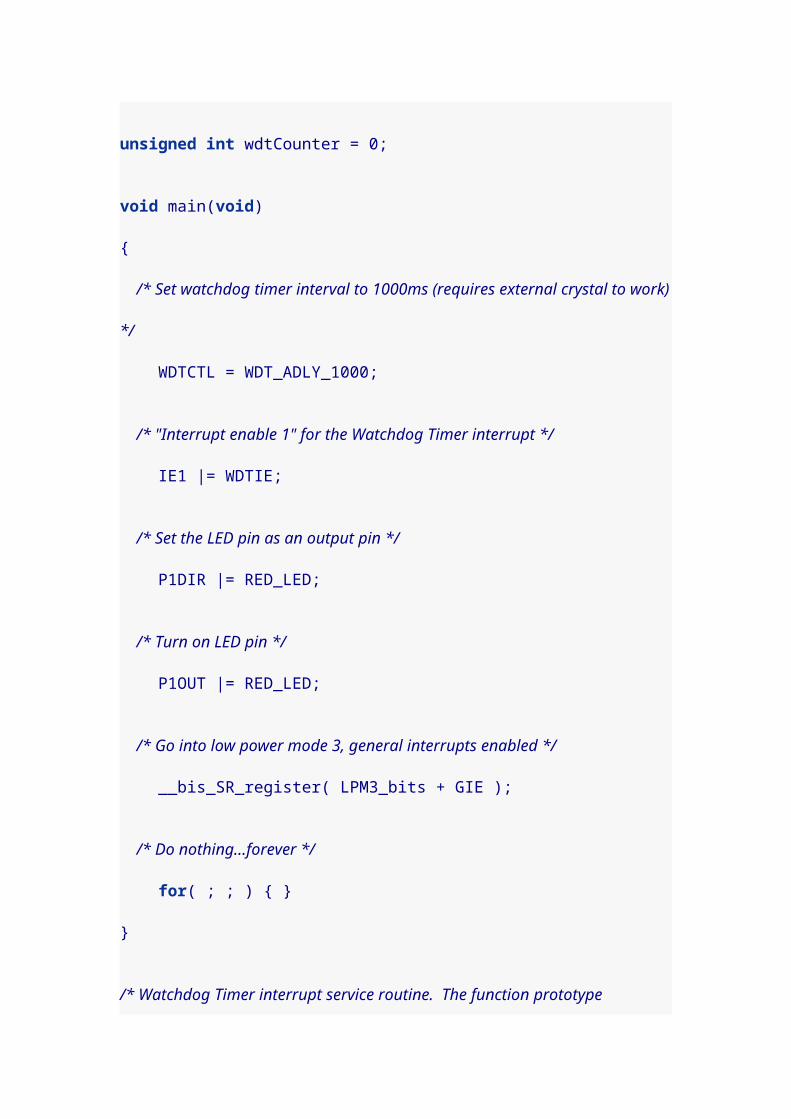
8.2. External timer crystals
If you have an external crystal, a couple of new things
become possible. One is that there is a "one second
timer," WDT_ADLY_1000 which we can use instead of
counting interrupts. The other is that we can put the chip to
sleep in a lower power mode than if we use the internal
clock. According to TI, when the chip is active, it uses
approximately 300 uA of current. When in LPM0 it uses
about 85 uA. But in LPM3, it uses only 1uA.
Soldering the 32.768 kHz crystal to your Launchpad is a bit
delicate, but I managed. You can see it in the blue oval:

With the crystal, we can revise our hello program:
#include <msp430g2211.h>
#define RED_LED BIT0
unsigned int wdtCounter = 0;
void main(void){ /* Set watchdog timer interval to 1000ms (requires external crystal to work) */ WDTCTL = WDT_ADLY_1000;

/* "Interrupt enable 1" for the Watchdog Timer interrupt */ IE1 |= WDTIE;
/* Set the LED pin as an output pin */ P1DIR |= RED_LED;
/* Turn on LED pin */ P1OUT |= RED_LED;
/* Go into low power mode 3, general interrupts enabled */ __bis_SR_register( LPM3_bits + GIE );
/* Do nothing...forever */ for( ; ; ) { }}
/* Watchdog Timer interrupt service routine. The function prototype * * tells the compiler that this will service the Watchdog Timer, and * * then the function follows. * */void watchdog_timer(void) __attribute__((interrupt(WDT_VECTOR)));void watchdog_timer(void){ wdtCounter++;
/* Count 1 interrupts x 1000ms = 1000ms, or one second */ if(wdtCounter == 1) { /* Blink the LED pin */ P1OUT ^= RED_LED;
/* Reset the counter for the next blink */ wdtCounter = 0; }}
9. Blinking lights revisited
9.1. Using internal timer

We have everything we need now to do a good job with the
"blinking lights" demo above, using interrupts to drive the
entire program. This code uses the internal timer, so there
is no need for an external crystal.
#include <msp430g2211.h>
#define RED_LED BIT0#define GRN_LED BIT6#define BUTTON BIT3
int blink_mode = 0; // which mode we start inint blink_mask = RED_LED; // which lights we blinkint wdtCounter = 0;
int main(void) { /* Set watchdog timer interval to 32ms */ WDTCTL = WDT_MDLY_32;
/* enable interrupts for the watchdog timer */ IE1 |= WDTIE;
/* Enable interrupts for our button */ P1IE |= BUTTON;
/* Clear our BUTTON in the Port 1 interrupt flag. */ P1IFG &= ~BUTTON;
/* Configure LED pins on port 1 as output pins */ P1DIR |= RED_LED + GRN_LED;
/* make sure green is turned off */ P1OUT &= ~GRN_LED;
/* go to sleep, low power mode 0 */ __bis_SR_register( LPM0_bits + GIE );
/* infinite loop */ for( ; ; ) { }}

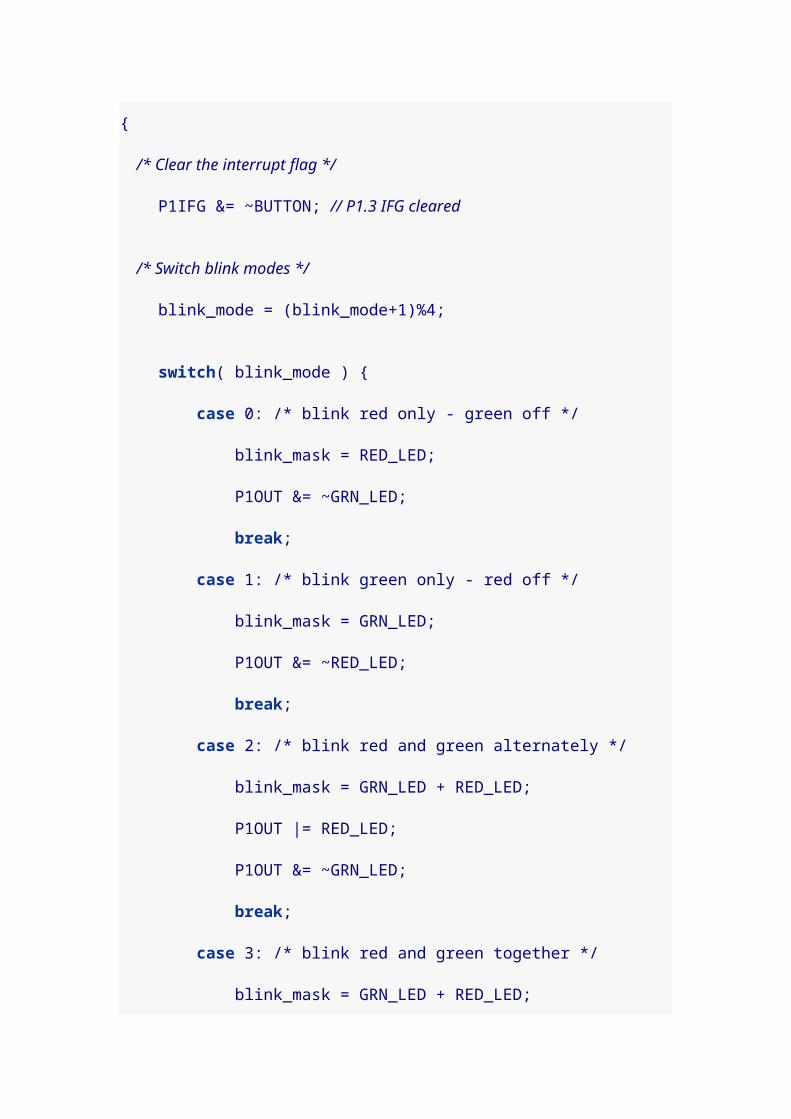
/* Port 1 interrupt service routine. This is for handling * our button presses. First, this prototype tells * the compiler that the function handles interrupts for * Port 1. Then the function follows. */void Port_1(void) __attribute__((interrupt(PORT1_VECTOR)));void Port_1(void){ /* Clear the interrupt flag */ P1IFG &= ~BUTTON; // P1.3 IFG cleared
/* Switch blink modes */ blink_mode = (blink_mode+1)%4;
switch( blink_mode ) { case 0: /* blink red only - green off */ blink_mask = RED_LED; P1OUT &= ~GRN_LED; break; case 1: /* blink green only - red off */ blink_mask = GRN_LED; P1OUT &= ~RED_LED; break; case 2: /* blink red and green alternately */ blink_mask = GRN_LED + RED_LED; P1OUT |= RED_LED; P1OUT &= ~GRN_LED; break; case 3: /* blink red and green together */ blink_mask = GRN_LED + RED_LED; P1OUT |= RED_LED + GRN_LED; break; }}
/* Watchdog Timer interrupt service routine. The function prototype * tells the compiler that this will service the Watchdog Timer, and * then the function follows. */void watchdog_timer(void) __attribute__((interrupt(WDT_VECTOR)));void watchdog_timer(void){

wdtCounter++;
/* Count 10 interrupts x 32ms = 320ms, about 1/3 second */ if(wdtCounter == 10) { /* Reset the counter for the next blink */ wdtCounter = 0;
/* blink the LEDs */ P1OUT ^= blink_mask; }}
9.2. Using external crystal
If we adapt the code for the external crystal, we can use the
more-efficient low power mode 3.
#include <msp430g2211.h>
#define RED_LED BIT0#define GRN_LED BIT6#define BUTTON BIT3
int blink_mode = 0; // which mode we start inint blink_mask = RED_LED; // which lights we blinkint wdtCounter = 0;
int main(void) { /* Set watchdog timer interval to 16ms, won't work without external crystal */ WDTCTL = WDT_ADLY_16;
/* enable interrupts for the watchdog timer */ IE1 |= WDTIE;
/* Enable interrupts for our button */ P1IE |= BUTTON;
/* Clear our BUTTON in the Port 1 interrupt flag. */ P1IFG &= ~BUTTON;
/* Configure LED pins on port 1 as output pins */ P1DIR |= RED_LED + GRN_LED;

/* make sure green is turned off */ P1OUT &= ~GRN_LED;
/* go to sleep, low power mode 0 */ __bis_SR_register( LPM3_bits + GIE );
/* infinite loop */ for( ; ; ) { }}
/* Port 1 interrupt service routine. This is for handling * our button presses. First, this prototype tells * the compiler that the function handles interrupts for * Port 1. Then the function follows. */void Port_1(void) __attribute__((interrupt(PORT1_VECTOR)));void Port_1(void){ /* Clear the interrupt flag */ P1IFG &= ~BUTTON; // P1.3 IFG cleared
/* Switch blink modes */ blink_mode = (blink_mode+1)%4;
switch( blink_mode ) { case 0: /* blink red only - green off */ blink_mask = RED_LED; P1OUT &= ~GRN_LED; break; case 1: /* blink green only - red off */ blink_mask = GRN_LED; P1OUT &= ~RED_LED; break; case 2: /* blink red and green alternately */ blink_mask = GRN_LED + RED_LED; P1OUT |= RED_LED; P1OUT &= ~GRN_LED; break; case 3: /* blink red and green together */ blink_mask = GRN_LED + RED_LED; P1OUT |= RED_LED + GRN_LED; break; }

}
/* Watchdog Timer interrupt service routine. The function prototype * tells the compiler that this will service the Watchdog Timer, and * then the function follows. */void watchdog_timer(void) __attribute__((interrupt(WDT_VECTOR)));void watchdog_timer(void){ wdtCounter++;
/* Count 20 interrupts x 16ms = 320ms, about 1/3 second */ if(wdtCounter == 20) { /* Reset the counter for the next blink */ wdtCounter = 0;
/* blink the LEDs */ P1OUT ^= blink_mask; }}
10. Pulse Width Modulation
10.1. Sleeping LED
I’ve been wanting a good PWM example for a while now.
There seems to be a lot to understand in order to set this up
well, but I eventually managed to slap together a "sleeping"
green LED program.
#include "msp430g2211.h"
#define GRN_LED BIT6
int pwmDirection = 1;
void main(void){ /* Set watchdog timer interval to 32ms, internal timer */
WDTCTL = WDT_MDLY_32;
/* enable interrupts for the watchdog timer */ IE1 |= WDTIE;
/* Set green LED for ouput and then to pulse width modulation */ P1DIR |= GRN_LED; P1SEL |= GRN_LED;
/* The count that determines the PWM period */ CCR0 = 1000-1;
/* CCR1 is the PWM duty cycle, i.e. how much of the cycle is on vs. off */ CCR1 = 1;
/* CCR1 reset/set -- high voltage below count and low voltage when past */ CCTL1 = OUTMOD_7;
/* Timer A control set to submain clock TASSEL_2 and count up mode MC_1 */ TACTL = TASSEL_2 + MC_1;
/* go to sleep, low power mode 0 */ __bis_SR_register(LPM0_bits + GIE);
/* infinite loop */ for( ; ; ) { }}
/* Watchdog Timer interrupt service routine. The function prototype * tells the compiler that this will service the Watchdog Timer, and * then the function follows. */void watchdog_timer(void) __attribute__((interrupt(WDT_VECTOR)));void watchdog_timer(void){ CCR1 += pwmDirection*20;
if( CCR1 > 980 || CCR1 < 20 ) pwmDirection = -pwmDirection;}

There’s really a lot to understand here. The beginning is
familiar; I set up the watchdog timer to generate interrupts.
That’s because I’m using the interrupt service routine to
change the brightness of my green LED, sequentially
raising the brightness and then lowering it.
By the way, I used the green LED because the red LED
apparently doesn’t do pulse width modulation. I’m not sure
yet what it does do when you set its bit to 1 in the P1SEL
variable. Green works, so we use green.
The key to understanding how PWM works is to know that it
uses a counter and a comparison value. The values CCR0
and CCR1 set this up. CCR0 sets the bounds for the
counter. In our program, it counts from 0 to 999. CCR1 sets
the comparison value, which is initially 1, though we change
it later in the watchdog_timer() function.
CCTL1 can be set to different values, depending on how you
want your pulses to look. The header file give a rundown of
the values:
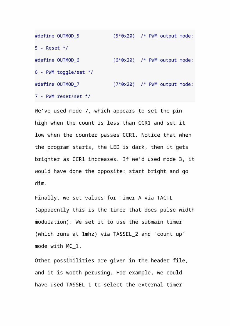
#define OUTMOD_0 (0*0x20) /* PWM output mode: 0 - output only */#define OUTMOD_1 (1*0x20) /* PWM output mode: 1 - set */#define OUTMOD_2 (2*0x20) /* PWM output mode: 2 - PWM toggle/reset */

#define OUTMOD_3 (3*0x20) /* PWM output mode: 3 - PWM set/reset */#define OUTMOD_4 (4*0x20) /* PWM output mode: 4 - toggle */#define OUTMOD_5 (5*0x20) /* PWM output mode: 5 - Reset */#define OUTMOD_6 (6*0x20) /* PWM output mode: 6 - PWM toggle/set */#define OUTMOD_7 (7*0x20) /* PWM output mode: 7 - PWM reset/set */
We’ve used mode 7, which appears to set the pin high when
the count is less than CCR1 and set it low when the counter
passes CCR1. Notice that when the program starts, the LED
is dark, then it gets brighter as CCR1 increases. If we’d
used mode 3, it would have done the opposite: start bright
and go dim.
Finally, we set values for Timer A via TACTL (apparently
this is the timer that does pulse width modulation). We set
it to use the submain timer (which runs at 1mhz) via
TASSEL_2 and "count up" mode with MC_1.
Other possibilities are given in the header file, and it is
worth perusing. For example, we could have used
TASSEL_1 to select the external timer crystal to run the
counter (if you’ve soldered yours to your Launchpad). The
crystal runs at only 32.678 kHz, though, so we’d probably

want to count to a value less than 999 in CCR0 (and scale
everything else accordingly) or we might notice flicker.
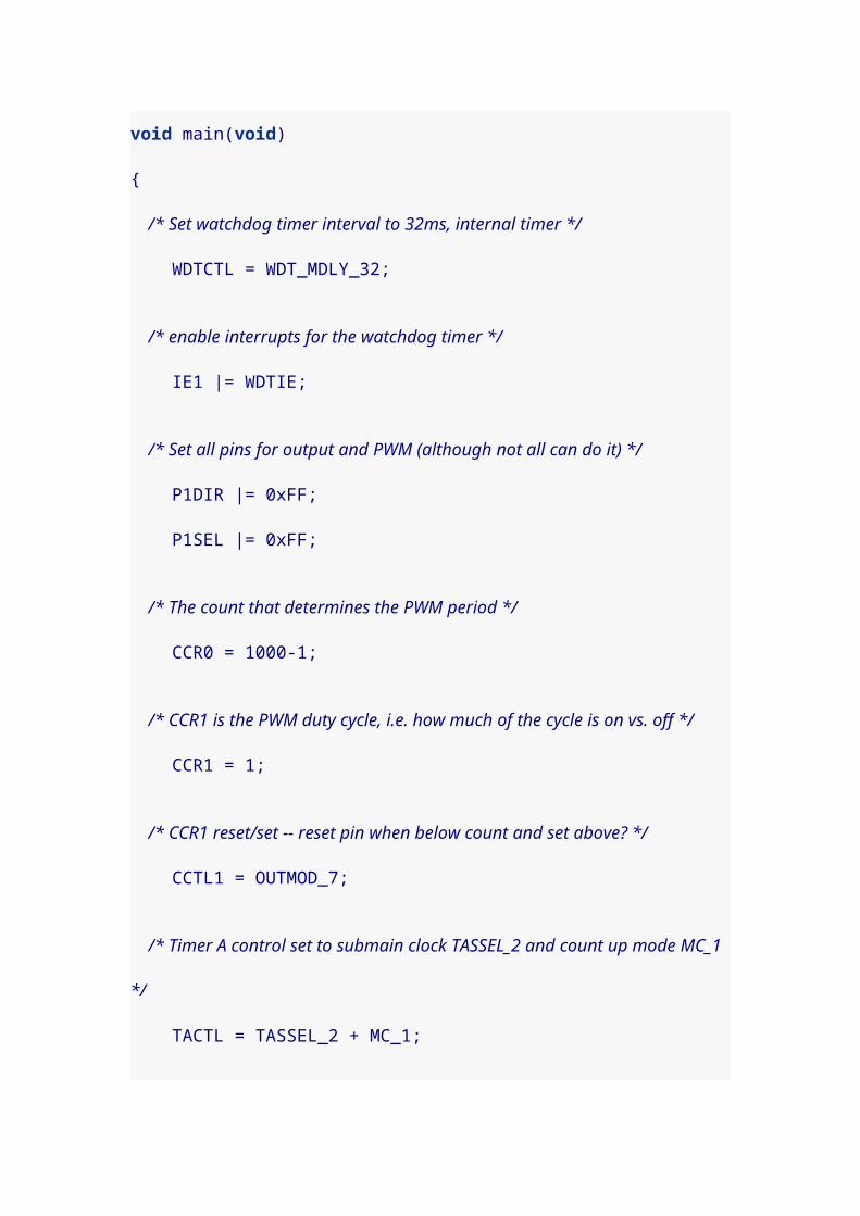
10.2. Which pins do PWM?
I didn’t know which pins can do pulse width modulation, so
I decided to modify the sleeping LED program to run all the
pins (or at least I used a bitmask for all of the pins). Then I
hooked up my multimeter to see which pins changed in time
with the green LED.
It appears that on the msp430g2211, the only pins that do
PWM are pin 1.2 and pin 1.6. Here’s the code I used; check
for yourself.
#include "msp430g2211.h"
int pwmDirection = 1;int wdtCounter = 0;
void main(void){ /* Set watchdog timer interval to 32ms, internal timer */ WDTCTL = WDT_MDLY_32;
/* enable interrupts for the watchdog timer */ IE1 |= WDTIE;
/* Set all pins for output and PWM (although not all can do it) */ P1DIR |= 0xFF; P1SEL |= 0xFF;
/* The count that determines the PWM period */ CCR0 = 1000-1;
/* CCR1 is the PWM duty cycle, i.e. how much of the cycle is on vs. off */ CCR1 = 1;
/* CCR1 reset/set -- reset pin when below count and set above? */ CCTL1 = OUTMOD_7;
/* Timer A control set to submain clock TASSEL_2 and count up mode MC_1 */ TACTL = TASSEL_2 + MC_1;
/* go to sleep, low power mode 0 */ __bis_SR_register(LPM0_bits + GIE);
/* infinite loop */ for( ; ; ) { }}
/* Watchdog Timer interrupt service routine. The function prototype * tells the compiler that this will service the Watchdog Timer, and * then the function follows. */void watchdog_timer(void) __attribute__((interrupt(WDT_VECTOR)));void watchdog_timer(void){ wdtCounter++;
/* We'll change every 2 interrupts to slow things a bit, so we have * time to watch on the multimeter. */ if( wdtCounter >= 2 ) { wdtCounter = 0;
CCR1 += pwmDirection*20;
if( CCR1 > 980 || CCR1 < 20 ) pwmDirection = -pwmDirection; }}
11. Talking to MSP430 via Launchpad USB interface

It is really, really tricky getting Linux to talk to the
Launchpad via the USB interface under Linux. I was able to
do it, but it requires executing these steps in exactly the
right order.
Step 1: Unplug the USB cable for the Launchpad and
reinsert it.
Step 2: Run the command mspdebug rf2500 exit
Step 3: Run the command stty 2400 -F /dev/ttyACM0
If this command executes successfully, you are basically
home free. But don’t get excited and mess up the order of
the next two steps!
Step 4: Execute the command cat /dev/ttyACM0
Step 5: If you are running the TI demo program with the temperature readings (the one that lights up the red LED when the temperature rises and the green LED when the temperature cools), press switch 2 to start the program. If the temperature of your room is at least 65°F, you should start seeing capital letters on your screen. (65 is the byte value of capital A, 66 is capital B, and so on).
If you do these steps out of order, you may get an error like /dev/ttyACM0: Input/output error or cat: /dev/ttyACM0: Input/output error. Do them in order.
Alternate steps that work if you are using a terminal
program like putty or minicom.
Step 1: Unplug the USB cable for the Launchpad and
reinsert it.

Step 2: Run the command mspdebug rf2500 exit
Step 3a: (For putty) Run putty, set it for serial, and connect
to /dev/ttyACM0 at speed 2400.
Step 3b: (For minicom) Run minicom -b 2400 -D /dev/ttyACM0
Step 4: Press switch 2 on the Launchpad to start reporting temperatures.
I’d suggest giving all of the commands on a single line. That will help make sure you can’t do anything in the wrong order. For example, it is much harder to get things wrong if you type: mspdebug rf2500 exit; stty 2400 -F /dev/ttyACM0; echo 'Go!'; cat /dev/ttyACM0
12. Yet another Hello World
Perhaps it’s silly to write yet another Hello World for the
MSP 430, but I was perusing some of the TI demo code for
the temperature demo, and I learned some new timer
tricks. The significant new thing is a way to use Low Power
Mode 3 and still trigger timer interrupts; but this method
doesn’t require an external clock crystal.
The trick is to use Timer A to trigger interrupts based on
counting (much like setting up pulse width modulation)
running off from the auxilliary clock ACLK, but to first
redefine ACLK to use the chip’s internal Very Low-power
Oscillator (LFXT1S_2) rather than the external crystal
oscillator (LFXT1S_0).
One extra touch in this program is the use of a clock divider
on the auxilliary clock with DIVA_1 (we divide the 12kHz
clock by two to create a 6kHz clock). We could have used
other values like DIVA_0 to use the full clock speed, if we
also changed the counter value from 5999 to 11999
correspondingly.
We could also have used DIVA_2 for a /4 divider (if we
counted to 2999) or DIVA_3 for a /8 divider (if we counted to 1499). All would
have given the same "1 second on 1 second off" blink time.
There’s also the possibility of using further clock dividers when setting up TACTL but this code didn’t do that. Check the header file about ID_0 through ID_3, and remember that you’ll want to change the counter value accordingly.
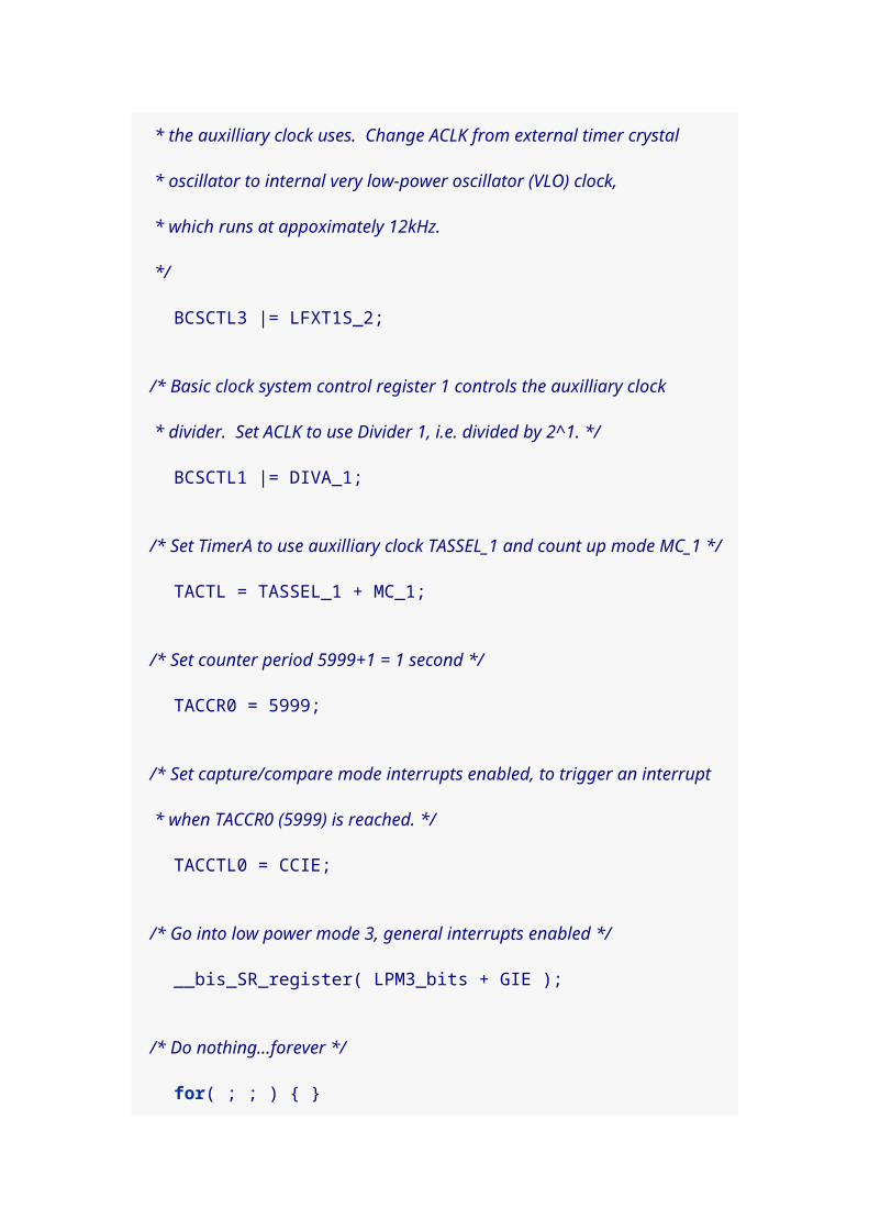
#include <msp430g2211.h>
#define RED_LED BIT0
unsigned int wdtCounter = 0;
void main(void){ /* Set the LED pin as an output pin and turn it on*/ P1DIR |= RED_LED; P1OUT |= RED_LED;
/* The basic clock system control register 3 controls the oscillator * the auxilliary clock uses. Change ACLK from external timer crystal * oscillator to internal very low-power oscillator (VLO) clock, * which runs at appoximately 12kHz. */ BCSCTL3 |= LFXT1S_2;
/* Basic clock system control register 1 controls the auxilliary clock

* divider. Set ACLK to use Divider 1, i.e. divided by 2^1. */ BCSCTL1 |= DIVA_1;
/* Set TimerA to use auxilliary clock TASSEL_1 and count up mode MC_1 */ TACTL = TASSEL_1 + MC_1;
/* Set counter period 5999+1 = 1 second */ TACCR0 = 5999;
/* Set capture/compare mode interrupts enabled, to trigger an interrupt * when TACCR0 (5999) is reached. */ TACCTL0 = CCIE;
/* Go into low power mode 3, general interrupts enabled */ __bis_SR_register( LPM3_bits + GIE );
/* Do nothing...forever */ for( ; ; ) { }}
/* Timer A interrupt service routine. The function prototype * tells the compiler that this will service the Timer A0 interrupt, * and then the function follows. */void Timer_A_isr(void) __attribute__((interrupt(TIMERA0_VECTOR)));void Timer_A_isr(void){ /* Blink the LED pin */ P1OUT ^= RED_LED;
/* clear interrupt flag */ TACCTL0 &= ~CCIFG;}
13. Serial communication 1
Some of the MSP430 chips have built-in serial
communication capabilities, but all of the chips should be

able to communicate serial via a method called "bit
banging." Bit banging is a technique of using the clock to
raise and lower a pin for the correct durations to send a
message.
This code also blinks the LEDs when transmitting, the red
led when sending a 1 and the green led when sending a 0.
You’ll notice after transmission, that the red light stays lit
(because the serial line is left high).
To communicate one byte a 0 is sent (called the start bit),
then the bits of the byte (in reverse order), then a 1 (called
the stop bit). If you set your computer’s serial line to the
correct speed, as detailed above [Talking_to_MSP430], you
should be able to see the message on screen.
About the "Ticks per bit" values… You might notice that the math suggests a value of 13 for 9600 bps, since 125000/9600 = 13.02. I found that 13 did not work for me, but 12 was fine. I also played with the 2400 bps value as well as the 1200 bps value. In general, I found that I could lower the constants a few places (effectively making the communication faster) without breaking things.
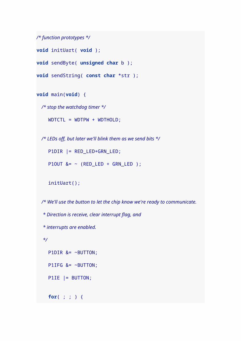
#include <msp430g2211.h>
/* Demo UART application. After you press the button, this transmits * a "Hello, world!" string to the computer at 2400 bps. */
#define RED_LED BIT0#define GRN_LED BIT6

#define BUTTON BIT3
#define TXD BIT1#define RXD BIT2
/* Ticks per bit. Use the following values based on speed: * 9600 bps -> 12 * 2400 bps -> 52 * 1200 bps -> 104 * I did not have success with slower speeds, like 300 bps. */#define TPB 52
int TXWord;unsigned char bitcnt = 0;
/* function prototypes */void initUart( void );void sendByte( unsigned char b );void sendString( const char *str );
void main(void) { /* stop the watchdog timer */ WDTCTL = WDTPW + WDTHOLD;
/* LEDs off, but later we'll blink them as we send bits */ P1DIR |= RED_LED+GRN_LED; P1OUT &= ~ (RED_LED + GRN_LED );
initUart();
/* We'll use the button to let the chip know we're ready to communicate. * Direction is receive, clear interrupt flag, and * interrupts are enabled. */ P1DIR &= ~BUTTON; P1IFG &= ~BUTTON; P1IE |= BUTTON;
for( ; ; ) { /* go to sleep until button press */ __bis_SR_register( LPM3_bits + GIE ); sendString( "Hello, world!\r\n" );
}}
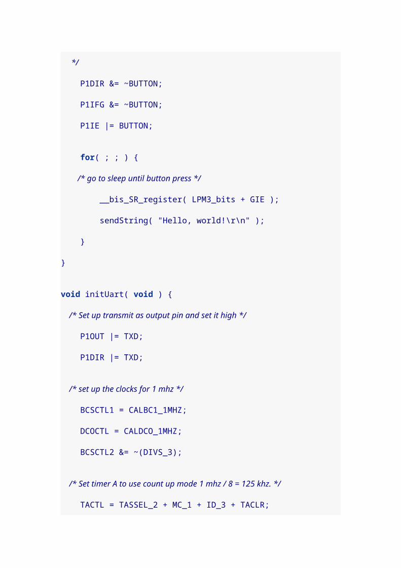
void initUart( void ) { /* Set up transmit as output pin and set it high */ P1OUT |= TXD; P1DIR |= TXD;
/* set up the clocks for 1 Mhz */ BCSCTL1 = CALBC1_1MHZ; DCOCTL = CALDCO_1MHZ; BCSCTL2 &= ~(DIVS_3);
/* Set timer A to use count up mode 4 Mhz / 8 = 500 Khz. */ TACTL = TASSEL_2 + MC_1 + ID_3 + TACLR;
/* Set ticks-per-bit to specify communication speed */ TACCR0 = TPB;}
void sendByte( unsigned char b ) { /* load the byte */ TXWord = b; /* add stop bit */ TXWord |= 0x100; /* add start bit */ TXWord <<= 1;
/* 1 start bit + 8 data bits + 1 stop bit */ bitcnt = 10;
/* clear the counter, clear interrupt flag, and tell Timer A0 to * start triggering interrupts */ TACTL |= TACLR; TACCTL0 &= ~CCIFG; TACCTL0 |= CCIE;
/* sleep until message sent */ while( TACCTL0 & CCIE ) { __bis_SR_register( LPM0_bits + GIE ); }}

/* Sends a string of characters to the computer */void sendString( const char *str ) { char *c = str;
for( ; *c ; c++ ) { sendByte( *c ); }}
/* This continuously sends bits of the TXWord starting from the * least significant bit (the 0 start bit). One bit is sent every * time the handler is activated. */void TimerA0 (void) __attribute__((interrupt(TIMERA0_VECTOR)));void TimerA0(void) { TACCTL0 &= ~CCIFG;
if( ! bitcnt ) { /* no bits left, turn off interrupts and wake up */ TACCTL0 &= ~ CCIE; __bic_SR_register_on_exit( LPM0_bits ); return; } else { /* send least significant bit */ if( TXWord & 0x01 ) { P1OUT |= TXD; P1OUT |= RED_LED; // for testing P1OUT &= ~ GRN_LED; // for testing } else { P1OUT &= ~TXD; P1OUT |= GRN_LED; // for testing P1OUT &= ~ RED_LED; // for testing }
/* shift word to remove one bit */ TXWord >>= 1; bitcnt --; }}
/* A button press triggers this interrupt, which wakes * up the main program to send a message. */

void Port_1 (void) __attribute__((interrupt(PORT1_VECTOR)));void Port_1(void) { P1IFG &= ~BUTTON;
/* wake up the main program */ __bic_SR_register_on_exit( LPM3_bits );}
14. Serial communication 2It seemed to me that our last serial communication program left a bit of empty time between consecutive bytes in a transmission, after the last stop bit is transmitted but before the next start bit goes out. If there is a whole block of data, it would be better if the next byte were just loaded and the communication continued. The next program does precisely that.
I have now changed the comments for the "Ticks per bit" for 9600 bps back to 13. By testing, I discovered that the previous program could be made reliable with a value 13 if I used a small delay to shorten the start bit. I think the setting of 12 accomplished something of the same result. In this program, there’s a bit of setup code that runs during that first interrupt, and it seems to provide adequate delay to make communication reliable.
#include <msp430g2211.h>#include <string.h>
/* Demo UART application. After you press the button, this transmits * a "Hello, world!" string to the computer at 2400 bps. */
#define RED_LED BIT0#define GRN_LED BIT6
#define BUTTON BIT3
#define TXD BIT1#define RXD BIT2
/* Ticks per bit. Use the following values based on speed: * 9600 bps -> 13 * 2400 bps -> 52 * 1200 bps -> 104 * I did not have success with slower speeds, like 300 bps.

*/#define TPB 52
/* A pointer to the data to send, and a counter of the bytes. */unsigned char *data;unsigned int bytestosend = 0;
/* The actual byte we are transmitting, with its start and stop bits, * and a counter of the bits left to send. */int TXWord;unsigned char bitcnt = 0;
/* function prototypes */void initUart( void );int sendByte( unsigned char b );int sendBytes( const unsigned char *d, int len );int sendString( const char *str );
void main(void) { /* stop the watchdog timer */ WDTCTL = WDTPW + WDTHOLD;
/* LEDs off, but later we'll blink them as we send bits */ P1DIR |= RED_LED+GRN_LED; P1OUT &= ~ (RED_LED + GRN_LED );
initUart();
/* We'll use the button to let the chip know we're ready to communicate. * Direction is receive, clear interrupt flag, and * interrupts are enabled. */ P1DIR &= ~BUTTON; P1IFG &= ~BUTTON; P1IE |= BUTTON;
for( ; ; ) { /* go to sleep until button press */ __bis_SR_register( LPM3_bits + GIE ); sendString( "Hello, world!\r\n" ); }}

void initUart( void ) { /* Set up transmit as output pin and set it high */ P1OUT |= TXD; P1DIR |= TXD;
/* set up the clocks for 1 mhz */ BCSCTL1 = CALBC1_1MHZ; DCOCTL = CALDCO_1MHZ; BCSCTL2 &= ~(DIVS_3);
/* Set timer A to use count up mode 1 mhz / 8 = 125 khz. */ TACTL = TASSEL_2 + MC_1 + ID_3 + TACLR;
/* Set ticks-per-bit to specify communication speed */ TACCR0 = TPB;}
/* Prepares a block of data to be sent. Returns number of bytes sent. */int sendBytes( const unsigned char *d, int len ) { /* can't queue up data if we're still sending */ if( bytestosend > 0 ) return 0;
bitcnt = 0; data = d; bytestosend = len;
/* clear interrupt flag, and tell Timer A0 to * start triggering interrupts */ TACCTL0 &= ~CCIFG; TACCTL0 |= CCIE;
/* sleep until message sent */ while( TACCTL0 & CCIE ) { __bis_SR_register( LPM0_bits + GIE ); }
return len;}
/* Sends a single byte to the computer. Returns number of bytes sent. */

int sendByte( unsigned char b ) { return sendBytes( &b, 1 );}
/* Sends a string to the computer. Returns number of bytes sent. */int sendString( const char *str ) { return sendBytes( str, strlen(str) );}
/* This continuously sends bits of the TXWord starting from the * least significant bit (the 0 start bit). One bit is sent every * time the handler is activated. When the bits run out, a new * byte is loaded from the data pointer, until bytestosend equals 0. */void TimerA0 (void) __attribute__((interrupt(TIMERA0_VECTOR)));void TimerA0(void) { TACCTL0 &= ~CCIFG;
/* if no bits to send, either load a byte or return */ if( ! bitcnt ) { if( bytestosend > 0 ) { /* load the byte */ TXWord = *data++; /* add stop bit */ TXWord |= 0x100; /* add start bit */ TXWord <<= 1;
/* 1 start bit + 8 data bits + 1 stop bit */ bitcnt = 10;
bytestosend --; } else { /* no bits left, turn off interrupts and wake up */ TACCTL0 &= ~ CCIE; __bic_SR_register_on_exit( LPM0_bits ); return; } }
/* send least significant bit */ if( TXWord & 0x01 ) { P1OUT |= TXD; P1OUT |= RED_LED; // for testing

P1OUT &= ~ GRN_LED; // for testing } else { P1OUT &= ~TXD; P1OUT |= GRN_LED; // for testing P1OUT &= ~ RED_LED; // for testing }
/* shift word to remove one bit */ TXWord >>= 1; bitcnt --;}
/* A button press triggers this interrupt, which wakes * up the main program to send a message. */void Port_1 (void) __attribute__((interrupt(PORT1_VECTOR)));void Port_1(void) { P1IFG &= ~BUTTON;
/* wake up the main program */ __bic_SR_register_on_exit( LPM3_bits );}
You may wonder that we didn’t just call sendString() directly
from the Port_1() interrupt handler in either this program or
the previous one. The reason we didn’t do that is
thatsendBytes() sleeps until the data has been sent. In
general, interrupts are disabled while in an interrupt
handler. If we go to sleep while in the button handler,
there’s no convenient way for the TimerA0() to trigger and
clear the data out.

It is possible to adjust the program so that we can
call sendString() directly from the Port_1() handler. We’d need
to make these changes.
1. Sleep in LPM0 instead of LPM3 in the main() function,
since Timer A0 can’t trigger in LPM3.
2. Remove the while loop and sleep code
from sendBytes() so it returns right away.
3. Remove the __bic_SR_register_on_exit() call
from Port_1() and replace it with a call to sendString().
15. Adding button debounce
If you tried the previous two serial communication
programs, you may notice that on occasion you got more
than one "Hello, world!" when you pressed Switch 2. That is
probably due to something called button bounce. When you
switch a physical button, it doesn’t always go cleanly from
high voltage to low voltage (or vice versa). There is often a
short period where the voltage oscillates back and forth
before settling. These bounces can trigger extra button
interrupts and repeated messages.

Button debouncing can be handled in hardware or software.
In software, we basically handle button bounce by ignoring
new interrupts for a short period of time after the initial
interrupt. In the next program, I’ve configured the
Watchdog timer to use the very low-power oscillator (VLO),
and used that to debounce the button.
Most of the changes occur in the Port_1() handler, which
now disables the button interrupt and enables the
Watchdog timer; and in the new WDT_ISR(), which catches a
Watchdog timer interrupt to re-enable the button. Don’t
overlook in the main program, however, where we set the
oscillator by modifying BCSCTL3.
#include <msp430g2211.h>#include <string.h>
/* Demo UART application. After you press the button, this transmits * a "Hello, world!" string to the computer at 2400 bps. */
#define RED_LED BIT0#define GRN_LED BIT6
#define BUTTON BIT3
#define TXD BIT1#define RXD BIT2
/* Ticks per bit. Use the following values based on speed: * 9600 bps -> 13 * 2400 bps -> 52

* 1200 bps -> 104 * I did not have success with slower speeds, like 300 bps. */#define TPB 52
/* A pointer to the data to send, and a counter of the bytes. */unsigned char *data;unsigned int bytestosend = 0;
/* The actual byte we are transmitting, with its start and stop bits, * and a counter of the bits left to send. */int TXWord;unsigned char bitcnt = 0;
/* function prototypes */void initUart( void );int sendByte( unsigned char b );int sendBytes( const unsigned char *d, int len );int sendString( const char *str );
void main(void) { /* stop the watchdog timer */ WDTCTL = WDTPW + WDTHOLD;
/* For debouncing: set the auxilliary clock to use very low-power * oscillator. Later, we'll have the Watchdog timer use the * auxilliary clock for debouncing the button. */ BCSCTL3 |= LFXT1S_2;
/* LEDs off, but later we'll blink them as we send bits */ P1DIR |= RED_LED+GRN_LED; P1OUT &= ~ (RED_LED + GRN_LED );
initUart();
/* We'll use the button to let the chip know we're ready to communicate. * Direction is receive, clear interrupt flag, and * interrupts are enabled. */ P1DIR &= ~BUTTON; P1IFG &= ~BUTTON;
P1IE |= BUTTON;
for( ; ; ) { /* go to sleep until button press */ __bis_SR_register( LPM3_bits + GIE ); sendString( "Hello, world!\r\n" ); }}
void initUart( void ) { /* Set up transmit as output pin and set it high */ P1OUT |= TXD; P1DIR |= TXD;
/* set up the clocks for 1 mhz */ BCSCTL1 = CALBC1_1MHZ; DCOCTL = CALDCO_1MHZ; BCSCTL2 &= ~(DIVS_3);
/* Set timer A to use count up mode 1 mhz / 8 = 125 khz. */ TACTL = TASSEL_2 + MC_1 + ID_3 + TACLR;
/* Set ticks-per-bit to specify communication speed */ TACCR0 = TPB;}
/* Prepares a block of data to be sent. Returns number of bytes sent. */int sendBytes( const unsigned char *d, int len ) { /* can't queue up data if we're still sending */ if( bytestosend > 0 ) return 0;
bitcnt = 0; data = d; bytestosend = len;
/* clear interrupt flag, and tell Timer A0 to * start triggering interrupts */ TACCTL0 &= ~CCIFG; TACCTL0 |= CCIE;
/* sleep until message sent */ while( TACCTL0 & CCIE ) {

__bis_SR_register( LPM0_bits + GIE ); }
return len;}
/* Sends a single byte to the computer. Returns number of bytes sent. */int sendByte( unsigned char b ) { return sendBytes( &b, 1 );}
/* Sends a string to the computer. Returns number of bytes sent. */int sendString( const char *str ) { return sendBytes( str, strlen(str) );}
/* This continuously sends bits of the TXWord starting from the * least significant bit (the 0 start bit). One bit is sent every * time the handler is activated. When the bits run out, a new * byte is loaded from the data pointer, until bytestosend equals 0. */void TimerA0 (void) __attribute__((interrupt(TIMERA0_VECTOR)));void TimerA0(void) { TACCTL0 &= ~CCIFG;
/* if no bits to send, either load a byte or return */ if( ! bitcnt ) { if( bytestosend > 0 ) { /* load the byte */ TXWord = *data++; /* add stop bit */ TXWord |= 0x100; /* add start bit */ TXWord <<= 1;
/* 1 start bit + 8 data bits + 1 stop bit */ bitcnt = 10;
bytestosend --; } else { /* no bits left, turn off interrupts and wake up */ TACCTL0 &= ~ CCIE; __bic_SR_register_on_exit( LPM0_bits );
return; } }
/* send least significant bit */ if( TXWord & 0x01 ) { P1OUT |= TXD; P1OUT |= RED_LED; // for testing P1OUT &= ~ GRN_LED; // for testing } else { P1OUT &= ~TXD; P1OUT |= GRN_LED; // for testing P1OUT &= ~ RED_LED; // for testing }
/* shift word to remove one bit */ TXWord >>= 1; bitcnt --;}
/* A button press triggers this interrupt, which wakes * up the main program to send a message. */void Port_1 (void) __attribute__((interrupt(PORT1_VECTOR)));void Port_1(void) { /* disable interrupts for the button to handle button bounce */ P1IE &= ~BUTTON; /* clear the interrupt flag for button */ P1IFG &= ~BUTTON;
/* set watchdog timer to trigger every 16*32.768k/12k = 44 ms */ WDTCTL = WDT_ADLY_16; /* clear watchdog timer interrupt flag */ IFG1 &= ~WDTIFG; /* enable watchdog timer interrupts; in 44 ms the button * will be re-enabled by WDT_ISR() -- program will continue in * the meantime. */ IE1 |= WDTIE;
/* wake up the main program */ __bic_SR_register_on_exit( LPM3_bits );}

/* This function catches watchdog timer interrupts, which are * set to happen 44ms after the user presses the button. The * button has had time to "bounce" and we can turn the button * interrupts back on. */void WDT_ISR(void) __attribute__((interrupt(WDT_VECTOR)));void WDT_ISR(void){ /* Disable interrupts on the watchdog timer */ IE1 &= ~WDTIE; /* clear the interrupt flag for watchdog timer */ IFG1 &= ~WDTIFG; /* resume holding the watchdog timer so it doesn't reset the chip */ WDTCTL = WDTPW + WDTHOLD; /* and re-enable interrupts for the button */ P1IE |= BUTTON;}
Normally WDT_ADLY_16 triggers interrupts every 16 milliseconds, but this value assumes you are using the 32.768k external crystal oscillator. Since we set the auxiallary clock to use the internal very low-power oscillator, which runs at a slower 12k rate, we get interrupts every 16*32.768k/12k = 43.7 ms. This should be long enough to debounce the button, but we could have added a counter to WDT_ISR() or set a clock divider by modifying BCSCTL1 (as in[Yet_another_hello]) if we needed longer delays.Since I wrote this experiment, it occurs to me that it is only half done. I had a button that would bounce when pressed (and this addresses it). But many buttons bounce when pressed and when released. We shouldn’t wake the program up in Port_1() but rather in WDT_ISR() if we check and the button is still down.
16. A Uart receiverI can’t believe how much time I spent getting the next application to work. I finally realize something about all of the TI demo code. If you use mspgcc4 for your projects, then this is really important. So I’m going to make a big warning sign here:

In TI code, interrupt handlers don’t clear the relevant interrupt flag. If you port this code to mspgcc4, you have to clear the interrupt flag in all of your interrupt handlers, or your code will not work! I assume the TI compiler must do this for you, and perhaps this is understood as part of what the #pragma directive does.
You’ll see that I clear the interrupt flag as the first line of
the TimerA1() interrupt handler.
The progam that follows is a simple Uart receiver. It talks to
the computer through the Launchpad device. When you
type characters on the computer (in a terminal program like
minicom) the LEDs on the Launchpad blink. The red LED
lights up for 1s, and the green LED lights up for 0s.
#include <msp430g2211.h>
/* Demo UART application. Receives bytes from the computer * at 2400 bps, and blinks the red LED for 1s and the green * LED for 0s. */
#define RED_LED BIT0#define GRN_LED BIT6
#define RXD BIT2
/* Ticks per bit, and ticks per half. Use the following values based on speed: * 9600 bps -> 13 * 2400 bps -> 52 * 1200 bps -> 104 * I did not have success with slower speeds, like 300 bps. */#define TPB 52#define TPH (TPB - TPB/2)

int RXByte;unsigned char bitcnt = 0;
/* function prototypes */void initUart( void );void RX_Ready( void );
void main(void) { /* stop the watchdog timer */ WDTCTL = WDTPW + WDTHOLD;
/* LEDs off, but we'll blink them as we send or receive bits */ P1DIR |= RED_LED+GRN_LED; P1OUT &= ~ (RED_LED + GRN_LED );
initUart();
for( ; ; ) { RX_Ready(); /* go to sleep and wait for data */ __bis_SR_register( LPM0_bits + GIE ); }}
void initUart( void ) { /* set up the clocks for 1 mhz */ BCSCTL1 = CALBC1_1MHZ; DCOCTL = CALDCO_1MHZ; BCSCTL2 &= ~(DIVS_3);
/* Set timer A to use continuous mode 1 mhz / 8 = 125 khz. */ TACTL = TASSEL_2 + MC_2 + ID_3;
/* RXD set for timer function as a receive pin */ P1SEL |= RXD; P1DIR &= ~ RXD;}
void RX_Ready( void ) { /* Make ready to receive character. Syncronize, negative edge * capture, enable interrupts. */ bitcnt = 8; CCTL1 = SCS + OUTMOD0 + CM1 + CAP + CCIE;

}
void TimerA1 (void) __attribute__((interrupt(TIMERA1_VECTOR)));void TimerA1(void) { /* reset the interrupt flag */ CCTL1 &= ~CCIFG;
/* add ticks per bit to trigger again on next bit in stream */ CCR1 += TPB;
/* If we just caught the 0 start bit, then turn off capture * mode (it'll be all compares from here forward) and add * tick-per-half so we'll catch signals in the middle of * each bit. */ if( CCTL1 & CAP ) { CCTL1 &= ~ CAP; CCR1 += TPH; } /* Otherwise we need to catch another bit. We'll shift right * the currently received data, and add new bits on the left. */ else { RXByte >>= 1;
if( CCTL1 & SCCI ) { RXByte |= 0x80; P1OUT |= RED_LED; // for testing P1OUT &= ~ GRN_LED; // for testing } else { P1OUT |= GRN_LED; // for testing P1OUT &= ~ RED_LED; // for testing } bitcnt --;
if( ! bitcnt ) { /* Go back to capture mode and wait for next start bit */ CCTL1 |= CAP; bitcnt = 8; P1OUT &= ~ (RED_LED + GRN_LED); // for testing
__bic_SR_register_on_exit( LPM0_bits ); } }

}
To use this program, I give a command like this:
$ mspdebug rf2500 exit; minicom -o -b 2400 -D /dev/ttyACM0...
17. Send and Receive
The next program sends and receives, and to some extent
can do both simultaneously. If you look, you’ll notice that
I’ve changed the transmitting code slightly to be more in
line with demo code from TI. This asserts high and low (or
mark and space as they are sometimes called) by
modifying CCTL0 and setting or clearing OUTMOD2. The effect
is essentially the same, though this seemed more reliable in
some situations.
Although the program works, there is a timing problem with
it. If you simply type characters on the computer, you will
not encounter the problem because you can’t type fast
enough. However, if the computer sends data to the
Launchpad too quickly, the program can still be
executing while( !sendByte( &onebyte )) ; when the start bit of
the next character arrives. If that happens, the next
characters will be garbled.
This can happen, for example, if the data is being sent by
software instead of from the keyboard. You can also observe
it if you use cut-and-paste to paste data into the terminal
program like minicom. Minicom will be happy to transfer
the pasted data faster than we can accept it on the
Launchpad.
#include <msp430g2211.h>
/* Demo UART application. Receives bytes from the computer * at 2400 bps, and sends the same character back to the computer. */
#define TXD BIT1#define RXD BIT2
/* Ticks per bit, and ticks per half. Use the following values based on speed: * 9600 bps -> 13 * 2400 bps -> 52 * 1200 bps -> 104 * I did not have success with slower speeds, like 300 bps. */#define TPB 52#define TPH (TPB - TPB/2)
unsigned int TXWord;unsigned char RXByte;unsigned char rxbitcnt = 0;unsigned char txbitcnt = 0;
/* A pointer to the data to send, and a counter of the bytes. */unsigned char *data;unsigned char onebyte = 0;unsigned int bytestosend = 0;
/* function prototypes */void initUart( void );

void RX_Ready( void );int sendByte( unsigned char *b ); // pointer to byte here!int sendBytes( const unsigned char *d, int len );int sendString( const char *str );int sendFinished( void );
void main(void) { /* stop the watchdog timer */ WDTCTL = WDTPW + WDTHOLD;
initUart();
for( ; ; ) { RX_Ready(); /* go to sleep and wait for data */ __bis_SR_register( LPM0_bits + GIE );
/* store byte so we can send and receive at same time */ onebyte = RXByte;
/* loop until the byte is queued to send */ while( !sendByte( &onebyte )) ; }}
void initUart( void ) { /* set up the clocks for 1 mhz */ BCSCTL1 = CALBC1_1MHZ; DCOCTL = CALDCO_1MHZ; BCSCTL2 &= ~(DIVS_3);
/* Set timer A to use continuous mode 1 mhz / 8 = 125 khz. */ TACTL = TASSEL_2 + MC_2 + ID_3;
/* When TXD isn't being used, it should be high */ CCTL0 = OUT;
/* TXD and RXD set for timer function, RXD input, TXD output */ P1SEL |= TXD + RXD; P1DIR &= ~ RXD; P1DIR |= TXD;}

/* Prepares a block of data to be sent. Returns number of bytes sent. */int sendBytes( const unsigned char *d, int len ) { /* can't queue up data if we're still sending */ if( CCTL0 & CCIE ) return 0;
txbitcnt = 0; data = d; bytestosend = len;
CCR0 = TAR + TPB;
/* Timer A0 to start triggering interrupts */ CCTL0 = CCIS0 + OUTMOD0 + CCIE;
return len;}
/* Sends a single byte to the computer. Returns number of bytes sent. */int sendByte( unsigned char *b ) { return sendBytes( b, 1 );}
/* Sends a string to the computer. Returns number of bytes sent. */int sendString( const char *str ) { return sendBytes( str, strlen(str) );}
/* Tests if a transmission is done */int sendFinished( void ) { return ( CCTL0 & CCIE ) == 0;}
/* This continuously sends bits of the TXWord starting from the * least significant bit (the 0 start bit). One bit is sent every * time the handler is activated. When the bits run out, a new * byte is loaded from the data pointer, until bytestosend equals 0. */void TimerA0 (void) __attribute__((interrupt(TIMERA0_VECTOR)));void TimerA0(void) { /* reset the interrupt flag */ CCTL0 &= ~CCIFG;

/* add ticks per bit to trigger again on next bit in stream */ CCR0 += TPB;
/* if no bits to send, either load a byte or return */ if( ! txbitcnt ) { if( bytestosend > 0 ) { /* load the byte */ TXWord = *data++; /* add stop bit */ TXWord |= 0x100; /* add start bit */ TXWord <<= 1;
/* 1 start bit + 8 data bits + 1 stop bit */ txbitcnt = 10;
bytestosend --; } else { /* no bits left, turn off interrupts */ CCTL0 &= ~ CCIE; return; } }
/* send least significant bit */ if( TXWord & 0x01 ) { CCTL0 &= ~ OUTMOD2; } else { CCTL0 |= OUTMOD2; }
/* shift word to remove one bit */ TXWord >>= 1; txbitcnt --;}
void RX_Ready( void ) { /* Make ready to receive character. Syncronize, negative edge * capture, enable interrupts. */ rxbitcnt = 8; CCTL1 = SCS + OUTMOD0 + CM1 + CAP + CCIE;}
void TimerA1 (void) __attribute__((interrupt(TIMERA1_VECTOR)));void TimerA1(void) { /* reset the interrupt flag */ CCTL1 &= ~CCIFG;
/* add ticks per bit to trigger again on next bit in stream */ CCR1 += TPB;
/* If we just caught the 0 start bit, then turn off capture * mode (it'll be all compares from here forward) and add * tick-per-half so we'll catch signals in the middle of * each bit. */ if( CCTL1 & CAP ) { CCTL1 &= ~ CAP; CCR1 += TPH; } /* Otherwise we need to catch another bit. We'll shift right * the currently received data, and add new bits on the left. */ else { RXByte >>= 1;
if( CCTL1 & SCCI ) { RXByte |= 0x80; } else { } rxbitcnt --;
if( ! rxbitcnt ) { /* we're done, no more interrupts */ CCTL1 &= ~ CCIE;
/* wake up the main program */ __bic_SR_register_on_exit( LPM0_bits ); } }}
To use this program, I give a command like this:
$ mspdebug rf2500 exit; minicom -o -b 2400 -D /dev/ttyACM0...

18. Send and Receive 2This program addresses the timing problem in the last piece of code by using a circular buffer to hold the incoming data. With the buffer, the Launchpad can return data to the computer much faster, and there is much less chance that the data (received by the Launchpad) will become garbled from missing a start bit. I also tried to tune the code a bit to make it more efficient, so it should be much harder to overwhelm the program and lose data.
I was unable to get the code to work at 9600 bps, so I removed the comment lines that suggested it would work. The problem seems to be with transmitting reliably back to the computer. The chip seems to receive at 9600 bps just fine.
#include <msp430g2211.h>
/* Demo UART application. Receives bytes from the computer * at 2400 bps, and sends the same byte back to the computer. */
#define RED_LED BIT0#define GRN_LED BIT6
#define TXD BIT1#define RXD BIT2
/* Ticks per bit, and ticks per half. Use the following values based on speed: * 2400 bps -> 52 * 1200 bps -> 104 * I did not have success with slower speeds, like 300 bps. */#define TPB 52#define TPH TPB/2
unsigned int TXWord = 0;unsigned char RXByte = 0;unsigned int rxbitcnt = 0;unsigned int txbitcnt = 0;
/* a circular buffer to for characters received/to send */#define BSIZE 16 // must be power of 2unsigned char buffer[BSIZE];unsigned int bhead=0, btail=0, bytestosend=0;

/* function prototypes */void initUart( void );inline void RX_Start( void );
void main(void) { /* stop the watchdog timer */ WDTCTL = WDTPW + WDTHOLD;
/* LEDs off, but we can use them for debugging if we want */ P1DIR |= RED_LED+GRN_LED; P1OUT &= ~ (RED_LED + GRN_LED );
initUart();
/* Start listening for data */ RX_Start();
for( ; ; ) { /* go to sleep and wait for data */ __bis_SR_register( LPM0_bits + GIE ); }}
void initUart( void ) { /* set up the clocks for 1 mhz */ BCSCTL1 = CALBC1_1MHZ; DCOCTL = CALDCO_1MHZ; BCSCTL2 &= ~(DIVS_3);
/* Set timer A to use continuous mode 1 mhz / 8 = 125 khz. */ TACTL = TASSEL_2 + MC_2 + ID_3;
/* When TXD isn't being used, it should be high */ CCTL0 = OUT;
/* TXD and RXD set for timer function, RXD input, TXD output */ P1SEL |= TXD + RXD; P1DIR &= ~ RXD; P1DIR |= TXD;}
/* This continuously sends bits of the TXWord starting from the * least significant bit (the 0 start bit). One bit is sent every * time the handler is activated. When the bits run out, a new

* byte is loaded from the data pointer, until bytestosend equals 0. */void TimerA0 (void) __attribute__((interrupt(TIMERA0_VECTOR)));void TimerA0(void) { if( txbitcnt ) { /* send least significant bit */ if( TXWord & 0x01 ) { CCTL0 &= ~ OUTMOD2; } else { CCTL0 |= OUTMOD2; } TXWord >>= 1; txbitcnt --; }
/* If there are no bits left, load the next byte */ if( !txbitcnt ) { if( bytestosend ) { /* load next byte with stop bit 0x100 and shifted left * to make the start bit */ TXWord = ( 0x100 | buffer[btail++]) << 1; btail &= BSIZE-1; bytestosend --;
/* 1 start bit + 8 data bits + 1 stop bit */ txbitcnt = 10; } else { /* turn off interrupts if not receiving */ if( ! rxbitcnt ) CCTL0 &= ~ CCIE; } }
/* add ticks per bit to trigger again on next bit in stream */ CCR0 += TPB; /* reset the interrupt flag */ CCTL0 &= ~CCIFG;}
void RX_Start( void ) { /* Make ready to receive character. Syncronize, negative edge * capture, enable interrupts. */ rxbitcnt = 8; CCTL1 = SCS + OUTMOD0 + CM1 + CAP + CCIE;

}
void TimerA1 (void) __attribute__((interrupt(TIMERA1_VECTOR)));void TimerA1(void) { /* If we just caught the 0 start bit, then turn off capture * mode (it'll be all compares from here forward) and add * ticks-per-half so we'll catch signals in the middle of * each bit. */ if( CCTL1 & CAP ) { /* 8 bits pending */ rxbitcnt = 8;
/* next interrupt in 1.5 bits (i.e. in middle of next bit) */ CCR1 += TPH + TPB;
/* reset capture mode and interrupt flag */ CCTL1 &= ~ ( CAP + CCIFG );
/* turn on transmitting also if needed */ if( ! (CCTL0 & CCIE)) { /* interleave the interrupts, transmit half-bit after receive */ CCR0 = CCR1 + TPH; CCTL0 = CCIS0 + OUTMOD0 + CCIE; }
return; }
/* Otherwise we need to catch another bit. We'll shift right * the currently received data, and add new bits on the left. */ RXByte >>= 1; if( CCTL1 & SCCI ) { RXByte |= 0x80; } rxbitcnt --;
/* last bit received */ if( ! rxbitcnt ) { /* Record this byte and reset for next. * Put character in circular buffer (unless full). */ if( bytestosend < BSIZE ) {

buffer[bhead++] = RXByte; bhead &= BSIZE-1; bytestosend ++; }
/* we're done, reset to capture */ CCTL1 = SCS + OUTMOD0 + CM1 + CAP + CCIE;
return; }
/* add ticks per bit to trigger again on next bit in stream */ CCR1 += TPB;
/* reset the interrupt flag */ CCTL1 &= ~CCIFG;}
To use this program, I give a command like this:
$ mspdebug rf2500 exit; minicom -o -b 2400 -D /dev/ttyACM0...
19. Increasing the clock speed
I’ve been thinking about the reason my UART code can’t do
9600 bps communications both ways without losing or
corrupting data. If we calculate, two way communication
requires handling 2*9600 = 19200 interrupts per second.
With the main clock running at 1Mhz, that means
1000000/19200 = 52 clock cycles are available to handle
each bit.
Just entering and returning from an interrupt uses 11 clock
cycles, leaving only 41 cycles on average for doing work.

There just isn’t time to finish up the work of one interrupt
when the next interrupt has to occur, and data bits get lost
in the receiving code or transmitted too late in the sending
code.
The MSP430 value line chips can run at faster clock speeds,
but there are no calibration settings recorded in the flash
memory for speeds faster than 1 Mhz. However, we can
figure out the settings by hand if we we have access to a
reliable clock source. If you have the clock crystal soldered
to your Launchpad, that will do the trick.
The key new code is the set_dco_c() function, which
calibrates and sets the digitally-controlled oscillator (DCO)
to change the clock speed. This is the code that requires an
external timer crystal, and the next program will not
function without one (so don’t bother unless you soldered
one to your Launchpad). Cite: this page gave me the idea
and the sample
code,http://jbremnant.wordpress.com/2011/01/03/nokia-lcd-
wiinunchuck-with-msp430/ .
#include <msp430g2211.h>
/* Demo UART application. Receives bytes from the computer * at 9600 bps, and sends the same byte back to the computer.

* This code requires an external clock crystal for calibration * of 4 Mhz clock speed. */
#define RED_LED BIT0#define GRN_LED BIT6
#define TXD BIT1#define RXD BIT2
/* Ticks per bit, and ticks per half. Use the following values based on speed: * 9600 bps -> 52 * 4800 bps -> 104 * 2400 bps -> 208 * 1200 bps -> 416 * I did not have success with slower speeds, like 300 bps. */#define TPB 52#define TPH TPB/2
unsigned int TXWord = 0;unsigned char RXByte = 0;unsigned int rxbitcnt = 0;unsigned int txbitcnt = 0;
/* a circular buffer to for characters received/to send */#define BSIZE 16 // must be power of 2unsigned char buffer[BSIZE];unsigned int bhead=0, btail=0, bytestosend=0;
/* function prototypes */unsigned char set_dco_c(unsigned int delta);void initUart( void );inline void RX_Start( void );
void main(void) { /* stop the watchdog timer */ WDTCTL = WDTPW + WDTHOLD;
/* LEDs off, but we can use them for debugging if we want */ P1DIR |= RED_LED+GRN_LED; P1OUT &= ~ (RED_LED + GRN_LED );
/* set clock speed and initialize the timers and data pins */ initUart();
/* Start listening for data */ RX_Start();
for( ; ; ) { /* go to sleep and wait for data */ __bis_SR_register( LPM0_bits + GIE ); }}
/* Pass a delta value to set the DCO speed. Values for delta: * 244 -> 1 MHz 1220 -> 5 Mhz 2197 -> 9 Mhz 3173 -> 13 Mhz * 488 -> 2 Mhz 1464 -> 6 Mhz 2441 -> 10 Mhz 3417 -> 14 Mhz * 732 -> 3 Mhz 1708 -> 7 Mhz 2685 -> 11 Mhz 3662 -> 15 Mhz * 976 -> 4 Mhz 1953 -> 8 Mhz 2929 -> 12 Mhz 3906 -> 16 Mhz * General formula: * floor(x hz / 4096) -> delta * Return values: * 0 - DCO set * 255 - Timeout * Adapted from code by J. B. Remnant. */unsigned char set_dco_c(unsigned int delta) { unsigned int Compare, Oldcapture = 0; volatile int i;
/* set auxilliary clock to use /8 divider (requires external crystal) */ BCSCTL1 |= DIVA_3; /* Timer A0 capture positive edge, select input 1, capture mode */ TACCTL0 = CM_1 + CCIS_1 + CAP; /* Timer A use submain clock, continuous up mode, clear timer */ TACTL = TASSEL_2 + MC_2 + TACLR; // SMCLK, cont-mode, clear
/* loop 10000 times to set clock */ for ( i = 10000; i; i-- ) { while (!(CCIFG & TACCTL0)) ; // Wait until capture occurred TACCTL0 &= ~CCIFG; // Capture occurred, clear flag Compare = TACCR0; // Get current captured SMCLK Compare = Compare - Oldcapture; // SMCLK difference

Oldcapture = TACCR0; // Save current captured SMCLK
if (delta == Compare) break; // If equal, leave the loop else if (delta < Compare) { DCOCTL--; // DCO is too fast, slow it down if (DCOCTL == 0xFF) // Did DCO roll under? if (BCSCTL1 & 0x0f) BCSCTL1--; // Select lower RSEL } else { DCOCTL++; // DCO is too slow, speed it up if (DCOCTL == 0x00) // Did DCO roll over? if ((BCSCTL1 & 0x0f) != 0x0f) BCSCTL1++; // Sel higher RSEL } }
TACCTL0 = 0; // Stop TACCR0 TACTL = 0; // Stop Timer_A BCSCTL1 &= ~DIVA_3; // ACLK = LFXT1CLK
/* i>0 means that DCO is set correctly -- set return value accordingly */ Compare = (i) ? 0 : 255;
/* delay loop */ for (i = 0; i < 0x4000; i++) ;
return Compare;}
void initUart( void ) { /* set clock speed to 4 Mhz no divider */ set_dco_c( 976 ); BCSCTL2 &= ~(DIVS_3);
/* Set timer A to use continuous mode 4 Mhz / 8 = 500 khz. */ TACTL = TASSEL_2 + MC_2 + ID_3;
/* When TXD isn't being used, it should be high */

CCTL0 = OUT;
/* TXD and RXD set for timer function, RXD input, TXD output */ P1SEL |= TXD + RXD; P1DIR &= ~ RXD; P1DIR |= TXD;}
/* This continuously sends bits of the TXWord starting from the * least significant bit (the 0 start bit). One bit is sent every * time the handler is activated. When the bits run out, a new * byte is loaded from the data pointer, until bytestosend equals 0. */void TimerA0 (void) __attribute__((interrupt(TIMERA0_VECTOR)));void TimerA0(void) { if( txbitcnt ) { /* send least significant bit */ if( TXWord & 0x01 ) { CCTL0 &= ~ OUTMOD2; } else { CCTL0 |= OUTMOD2; } TXWord >>= 1; txbitcnt --; }
/* If there are no bits left, load the next byte */ if( !txbitcnt ) { if( bytestosend ) { /* load next byte with stop bit 0x100 and shifted left * to make the start bit */ TXWord = ( 0x100 | buffer[btail++]) << 1; btail &= BSIZE-1; bytestosend --;
/* 1 start bit + 8 data bits + 1 stop bit */ txbitcnt = 10; } else { /* turn off interrupts if not receiving */ if( ! rxbitcnt ) CCTL0 &= ~ CCIE; } }
/* add ticks per bit to trigger again on next bit in stream */

CCR0 += TPB; /* reset the interrupt flag */ CCTL0 &= ~CCIFG;}
void RX_Start( void ) { /* Make ready to receive character. Syncronize, negative edge * capture, enable interrupts. */ rxbitcnt = 8; CCTL1 = SCS + OUTMOD0 + CM1 + CAP + CCIE;}
void TimerA1 (void) __attribute__((interrupt(TIMERA1_VECTOR)));void TimerA1(void) { /* If we just caught the 0 start bit, then turn off capture * mode (it'll be all compares from here forward) and add * ticks-per-half so we'll catch signals in the middle of * each bit. */ if( CCTL1 & CAP ) { /* 8 bits pending */ rxbitcnt = 8;
/* next interrupt in 1.5 bits (i.e. in middle of next bit) */ CCR1 += TPH + TPB;
/* reset capture mode and interrupt flag */ CCTL1 &= ~ ( CAP + CCIFG );
/* turn on transmitting also if needed */ if( ! (CCTL0 & CCIE)) { /* interleave the interrupts, transmit half-bit after receive */ CCR0 = CCR1 + TPH; CCTL0 = CCIS0 + OUTMOD0 + CCIE; }
return; }
/* Otherwise we need to catch another bit. We'll shift right * the currently received data, and add new bits on the left. */ RXByte >>= 1;
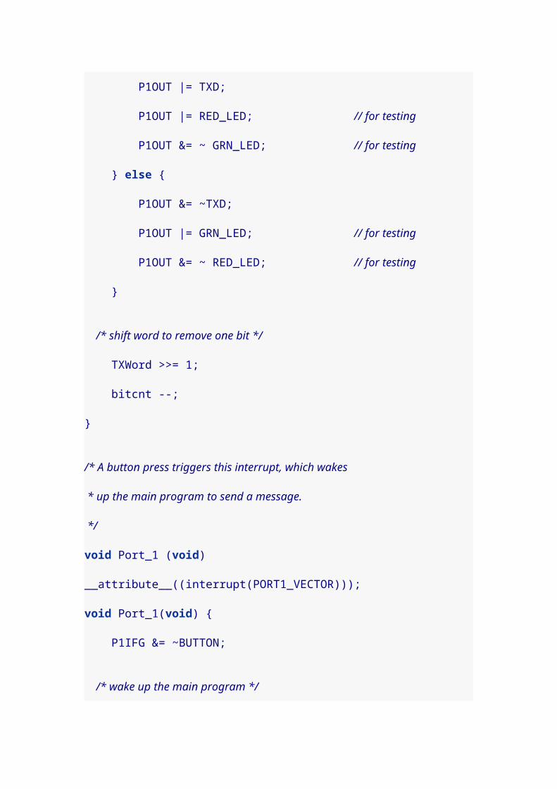
if( CCTL1 & SCCI ) { RXByte |= 0x80; } rxbitcnt --;
/* last bit received */ if( ! rxbitcnt ) { /* Record this byte and reset for next. * Put character in circular buffer (unless full). */ if( bytestosend < BSIZE ) { buffer[bhead++] = RXByte; bhead &= BSIZE-1; bytestosend ++; }
/* we're done, reset to capture */ CCTL1 = SCS + OUTMOD0 + CM1 + CAP + CCIE;
return; }
/* add ticks per bit to trigger again on next bit in stream */ CCR1 += TPB;
/* reset the interrupt flag */ CCTL1 &= ~CCIFG;}
Although the external timer crystal is required to run the calibration routine, if we save the calibration value it wouldn’t need to be determined every time. Altough it will change somewhat with conditions (like voltage or temperature) the fluctuations are probably not important. We could determine the value one time using our Launchpad, and then hard code the calibration value into a program, and the chip would work fine without the crystal.
20. Reading off calibration values
Since we’ve figured out how to calibrate the MSP 430 value
line chips (like the 2211 and 2231) for faster speeds, I

thought we should have a program that would let us know
what the settings are. That way we can take a particular
chip and run it in a context that doesn’t have an external
clock.
The next program puts together a lot of the things we’ve
learned to this point:
blinking LEDs
triggering interrupts on button presses
serial transmission to the PC via the Launchpad
interface
setting and calibrating the MSP 430 clock speed
#include <io.h>#include <string.h>
#define RED_LED BIT0#define GRN_LED BIT6
#define BUTTON BIT3
#define TXD BIT1#define RXD BIT2
#ifndef CALDCO_16MHZ_ #define CALDCO_16MHZ_ 0x10F8 /* DCOCTL Calibration Data for 16MHz */ const_sfrb(CALDCO_16MHZ, CALDCO_16MHZ_); #define CALBC1_16MHZ_ 0x10F9 /* BCSCTL1 Calibration Data for 16MHz */ const_sfrb(CALBC1_16MHZ, CALBC1_16MHZ_);#endif

#ifndef CALDCO_12MHZ_ #define CALDCO_12MHZ_ 0x10FA /* DCOCTL Calibration Data for 12MHz */ const_sfrb(CALDCO_12MHZ, CALDCO_12MHZ_); #define CALBC1_12MHZ_ 0x10FB /* BCSCTL1 Calibration Data for 12MHz */ const_sfrb(CALBC1_12MHZ, CALBC1_12MHZ_);#endif
#ifndef CALDCO_8MHZ_ #define CALDCO_8MHZ_ 0x10FC /* DCOCTL Calibration Data for 8MHz */ const_sfrb(CALDCO_8MHZ, CALDCO_8MHZ_); #define CALBC1_8MHZ_ 0x10FD /* BCSCTL1 Calibration Data for 8MHz */ const_sfrb(CALBC1_8MHZ, CALBC1_8MHZ_);#endif
/* Ticks per bit, and ticks per half. * 2400 bps -> 52 */#define TPB 52#define TPH (TPB/2)
unsigned char *data;unsigned int bytestosend=0;unsigned int TXWord = 0;unsigned int txbitcnt = 0;
/* for converting hex values to characters */unsigned char hex[] = "0123456789ABCDEF";
/* prototypes */unsigned char set_dco_c(unsigned int delta);void initUart( void );int sendString( char *str );void report_data( void );
unsigned int calbc1_1mhz, caldco_1mhz, calbc1_8mhz, caldco_8mhz, calbc1_12mhz, caldco_12mhz, calbc1_16mhz, caldco_16mhz;

/************ main program starts here ******************/void main( void ) { /* stop the watchdog timer */ WDTCTL = WDTPW + WDTHOLD;
/* LEDs off for now, but ready */ P1DIR |= RED_LED+GRN_LED; P1OUT &= ~ (RED_LED + GRN_LED );
/* start from the 1Mhz calibration values */ BCSCTL1 = CALBC1_1MHZ; DCOCTL = CALDCO_1MHZ;
/* calculate our own 1Mhz values */ if( !set_dco_c( 244 )) { calbc1_1mhz = BCSCTL1; caldco_1mhz = DCOCTL; } else { calbc1_1mhz = caldco_1mhz = 0xff; }
/* calculate our own 8Mhz values */ if( !set_dco_c( 1953 )) { calbc1_8mhz = BCSCTL1; caldco_8mhz = DCOCTL; } else { calbc1_8mhz = caldco_8mhz = 0xff; }
/* calculate our own 12Mhz values */ if( !set_dco_c( 2929 )) { calbc1_12mhz = BCSCTL1; caldco_12mhz = DCOCTL; } else { calbc1_12mhz = caldco_12mhz = 0xff; }
/* calculate our own 16Mhz values */ if( !set_dco_c( 3662 )) { calbc1_16mhz = BCSCTL1; caldco_16mhz = DCOCTL; } else { calbc1_16mhz = caldco_16mhz = 0xff; }

/* get ready to transmit to the computer */ initUart();
/* turn on red LED so we know calibration is done */ P1OUT |= RED_LED;
/* We'll use the button to let the chip know we're ready to communicate. * Button direction is receive, clear interrupt flag */ P1DIR &= ~BUTTON; P1IFG &= ~BUTTON;
while( 1 ) { /* done -- go to sleep and wait for button interrupt to report to PC */ P1IE |= BUTTON; __bis_SR_register( LPM3_bits + GIE );
P1OUT ^= RED_LED; report_data(); }}
/* Pass a delta value to set the DCO speed. Values for delta: * 244 -> 1 MHz 1220 -> 5 Mhz 2197 -> 9 Mhz 3173 -> 13 Mhz * 488 -> 2 Mhz 1464 -> 6 Mhz 2441 -> 10 Mhz 3417 -> 14 Mhz * 732 -> 3 Mhz 1708 -> 7 Mhz 2685 -> 11 Mhz 3662 -> 15 Mhz * 976 -> 4 Mhz 1953 -> 8 Mhz 2929 -> 12 Mhz 3906 -> 16 Mhz * General formula: * floor(x hz / 4096) -> delta * Return values: * 0 - DCO set * 255 - Timeout * Adapted from code by J. B. Remnant. */unsigned char set_dco_c(unsigned int delta) { unsigned int Compare, Oldcapture = 0;
/* set auxilliary clock to use /8 divider (requires external crystal) */ BCSCTL1 |= DIVA_3; /* Timer A0 capture positive edge, select input 1, capture mode */ TACCTL0 = CM_1 + CCIS_1 + CAP;

/* Timer A use submain clock, continuous up mode, clear timer */ TACTL = TASSEL_2 + MC_2 + TACLR; // SMCLK, cont-mode, clear
/* loop 10000 times to set clock */ volatile int i; for ( i = 10000; i; i-- ) { while (!(CCIFG & TACCTL0)) ; // Wait until capture occurred TACCTL0 &= ~CCIFG; // Capture occurred, clear flag Compare = TACCR0; // Get current captured SMCLK Compare = Compare - Oldcapture; // SMCLK difference Oldcapture = TACCR0; // Save current captured SMCLK
if (delta == Compare) break; // If equal, leave the loop else if (delta < Compare) { DCOCTL--; // DCO is too fast, slow it down if (DCOCTL == 0xFF) // Did DCO roll under? if (BCSCTL1 & 0x0f) BCSCTL1--; // Select lower RSEL } else { DCOCTL++; // DCO is too slow, speed it up if (DCOCTL == 0x00) // Did DCO roll over? if ((BCSCTL1 & 0x0f) != 0x0f) BCSCTL1++; // Sel higher RSEL } }
TACCTL0 = 0; // Stop TACCR0 TACTL = 0; // Stop Timer_A BCSCTL1 &= ~DIVA_3; // ACLK = LFXT1CLK
/* i>0 means that DCO is set correctly -- set return value accordingly */ Compare = (i) ? 0 : 255;
/* delay loop */ for (i = 0; i < 0x4000; i++) ;

return Compare;}
void initUart( void ) { /* set up the clocks for 1 mhz */ BCSCTL1 = CALBC1_1MHZ; DCOCTL = CALDCO_1MHZ; BCSCTL2 &= ~(DIVS_3);
/* Set timer A to use continuous mode 1 Mhz / 8 = 125 khz. */ TACTL = TASSEL_2 + MC_2 + ID_3 + TACLR;
/* When TXD isn't being used, it should be high */ CCTL0 = OUT;
/* TXD and RXD set for timer function, RXD input, TXD output */ P1SEL |= TXD + RXD; P1DIR &= ~ RXD; P1DIR |= TXD;}
/* This continuously sends bits of the TXWord starting from the * least significant bit (the 0 start bit). One bit is sent every * time the handler is activated. When the bits run out, a new * byte is loaded from the data pointer, until bytestosend equals 0. */void TimerA0 (void) __attribute__((interrupt(TIMERA0_VECTOR)));void TimerA0(void) { if( txbitcnt ) { /* send least significant bit */ if( TXWord & 0x01 ) { CCTL0 &= ~ OUTMOD2; } else { CCTL0 |= OUTMOD2; } TXWord >>= 1; txbitcnt --; }
/* If there are no bits left, load the next byte */ if( !txbitcnt ) { if( bytestosend ) { /* load next byte with stop bit 0x100 and shifted left * to make the start bit */

TXWord = ( 0x100 | *data++ ) << 1; bytestosend --;
/* 1 start bit + 8 data bits + 1 stop bit */ txbitcnt = 10; } else { /* turn off interrupts */ CCTL0 &= ~ CCIE; /* wake up the main program */ __bic_SR_register_on_exit( LPM0_bits ); } }
/* add ticks per bit to trigger again on next bit in stream */ CCR0 += TPB; /* reset the interrupt flag */ CCTL0 &= ~CCIFG;}
/* Prepares a block of data to be sent. */int sendBytes( unsigned char *d, int len ) { /* can't queue up data if we're still sending */ if( bytestosend > 0 ) return 0;
txbitcnt = 0; data = d; bytestosend = len;
/* Make sure we don't catch the TAR register while it is changing. * As long as the difference is only in the lower bits, we'll call * it close enough. */ do { CCR0 = TAR; } while( (CCR0^TAR) > 3 );
CCR0 += TPB;
/* Timer A0 to start triggering interrupts */ CCTL0 = CCIS0 + OUTMOD0 + CCIE;
/* sleep until message sent */ while( CCTL0 & CCIE ) { __bis_SR_register( LPM0_bits + GIE );

}
return len;}
/* Sends a single byte to the computer */int sendByte( unsigned char b ) { return sendBytes( &b, 1 );}
/* Sends a string of characters to the computer */int sendString( char *str ) { return sendBytes( str, strlen(str) );}
/* A button press triggers this interrupt, which wakes * up the main program to send a message. */void Port_1 (void) __attribute__((interrupt(PORT1_VECTOR)));void Port_1(void) { /* clear interrupt flag */ P1IFG &= ~BUTTON; /* disable button (will be re-enabled in main program) */ P1IE |= BUTTON;
/* wake up the main program */ __bic_SR_register_on_exit( LPM3_bits );}
void report_data( void ) { char str[] = "0x../0x..\r\n";
sendString( "Stock 1Mhz settings BCSCTL1/DCOCTL:" ); str[2] = hex[( CALBC1_1MHZ>>4 ) & 0x0F]; str[3] = hex[( CALBC1_1MHZ>>0 ) & 0x0F]; str[7] = hex[( CALDCO_1MHZ>>4 ) & 0x0F]; str[8] = hex[( CALDCO_1MHZ>>0 ) & 0x0F]; sendString( str ); sendString( "Derived: " ); str[2] = hex[( calbc1_1mhz>>4 ) & 0x0F]; str[3] = hex[( calbc1_1mhz>>0 ) & 0x0F]; str[7] = hex[( caldco_1mhz>>4 ) & 0x0F]; str[8] = hex[( caldco_1mhz>>0 ) & 0x0F]; sendString( str );

sendString( "Stock 8Mhz settings BCSCTL1/DCOCTL:" ); str[2] = hex[( CALBC1_8MHZ>>4 ) & 0x0F]; str[3] = hex[( CALBC1_8MHZ>>0 ) & 0x0F]; str[7] = hex[( CALDCO_8MHZ>>4 ) & 0x0F]; str[8] = hex[( CALDCO_8MHZ>>0 ) & 0x0F]; sendString( str ); sendString( "Derived: " ); str[2] = hex[( calbc1_8mhz>>4 ) & 0x0F]; str[3] = hex[( calbc1_8mhz>>0 ) & 0x0F]; str[7] = hex[( caldco_8mhz>>4 ) & 0x0F]; str[8] = hex[( caldco_8mhz>>0 ) & 0x0F]; sendString( str );
sendString( "Stock 12Mhz settings BCSCTL1/DCOCTL:" ); str[2] = hex[( CALBC1_12MHZ>>4 ) & 0x0F]; str[3] = hex[( CALBC1_12MHZ>>0 ) & 0x0F]; str[7] = hex[( CALDCO_12MHZ>>4 ) & 0x0F]; str[8] = hex[( CALDCO_12MHZ>>0 ) & 0x0F]; sendString( str ); sendString( "Derived: " ); str[2] = hex[( calbc1_12mhz>>4 ) & 0x0F]; str[3] = hex[( calbc1_12mhz>>0 ) & 0x0F]; str[7] = hex[( caldco_12mhz>>4 ) & 0x0F]; str[8] = hex[( caldco_12mhz>>0 ) & 0x0F]; sendString( str );
sendString( "Stock 16Mhz settings BCSCTL1/DCOCTL:" ); str[2] = hex[( CALBC1_16MHZ>>4 ) & 0x0F]; str[3] = hex[( CALBC1_16MHZ>>0 ) & 0x0F]; str[7] = hex[( CALDCO_16MHZ>>4 ) & 0x0F]; str[8] = hex[( CALDCO_16MHZ>>0 ) & 0x0F]; sendString( str ); sendString( "Derived: " ); str[2] = hex[( calbc1_16mhz>>4 ) & 0x0F]; str[3] = hex[( calbc1_16mhz>>0 ) & 0x0F]; str[7] = hex[( caldco_16mhz>>4 ) & 0x0F]; str[8] = hex[( caldco_16mhz>>0 ) & 0x0F]; sendString( str );}

To use the program, compile it for your target chip. Then
execute a terminal program, and press Switch 2 on the
Launchpad. The commands I used look like this:
$ msp430-gcc -O2 -mmcu=msp430x2211 -o calibrate.elf calibrate.c$ mspdebug rf2500 "prog calibrate.elf" ; minicom -o -b 2400 -D /dev/ttyACM0
The data I get back from the chip looks something like this:
Stock 1Mhz settings BCSCTL1/DCOCTL:0x86/0xA0Derived: 0x86/0xA7Stock 8Mhz settings BCSCTL1/DCOCTL:0x02/0x01Derived: 0x8C/0xD5Stock 12Mhz settings BCSCTL1/DCOCTL:0xFF/0xFFDerived: 0x8E/0x6FStock 16Mhz settings BCSCTL1/DCOCTL:0xFF/0xFFDerived: 0x8E/0xCA
Notice that the Stock settings for 1Mhz, which the program
reads from the flash memory, are very close to the Derived
settings. I think that is reassuring. For this particular chip, I
can set BCSCTL1 and DCOCTL to any of the derived
calibration pairs and expect to get a fairly accurate clock
speed.
21. A more robust calibration program
It turned out that the previous calibration program could
refuse to settle on a single calibration value. Sometimes it
would try one calibration, find it too slow, and speed the
oscillator up. But then the next value was too high, so it
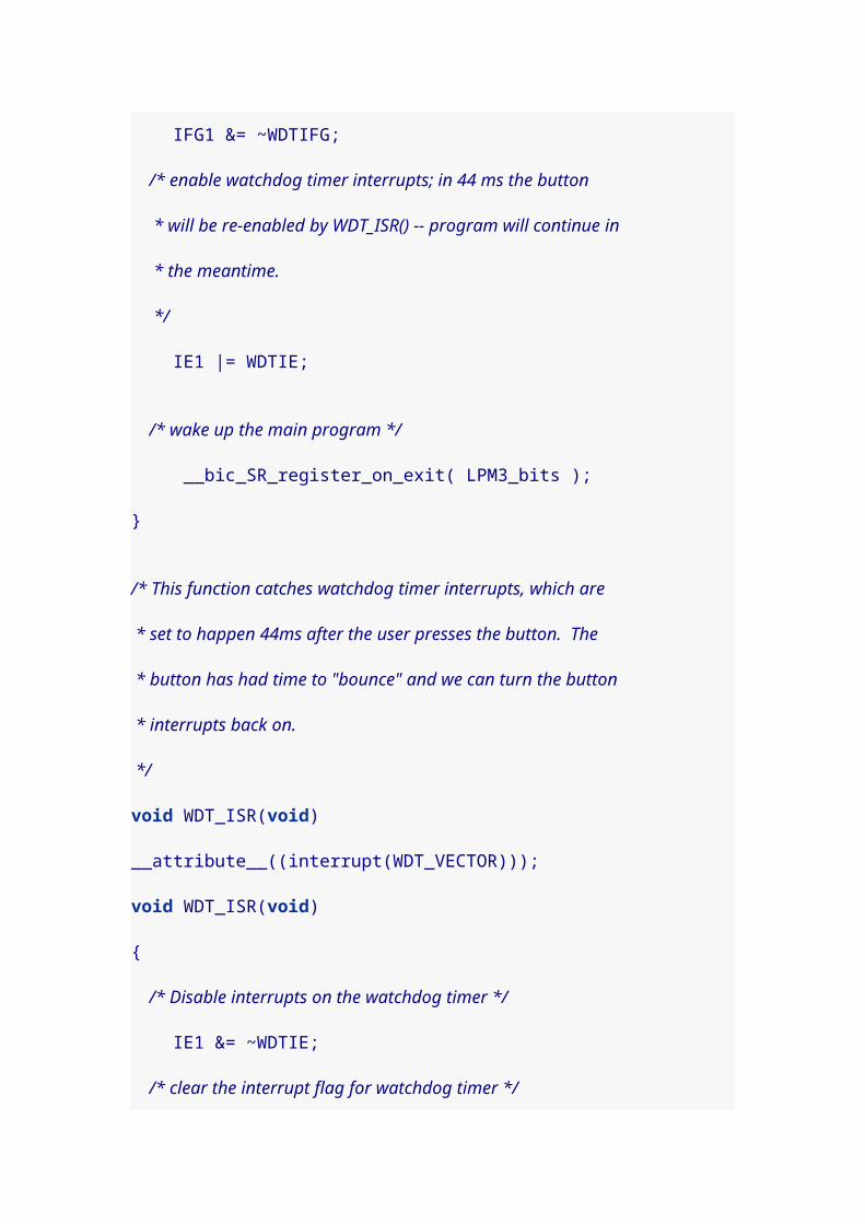
would slow the oscillator down. Eventually the loop would
time out, with no value being set.
To correct it, I added a bit of code to check for direction
changes in the oscillator tuning loop. If we change direction
4 times between two consecutive calibration values, that’s
close enough. We can return either value and be happy with
it.
#include <io.h>#include <string.h>
#define RED_LED BIT0#define GRN_LED BIT6
#define BUTTON BIT3
#define TXD BIT1#define RXD BIT2
#ifndef CALDCO_16MHZ_ #define CALDCO_16MHZ_ 0x10F8 /* DCOCTL Calibration Data for 16MHz */ const_sfrb(CALDCO_16MHZ, CALDCO_16MHZ_); #define CALBC1_16MHZ_ 0x10F9 /* BCSCTL1 Calibration Data for 16MHz */ const_sfrb(CALBC1_16MHZ, CALBC1_16MHZ_);#endif
#ifndef CALDCO_12MHZ_ #define CALDCO_12MHZ_ 0x10FA /* DCOCTL Calibration Data for 12MHz */ const_sfrb(CALDCO_12MHZ, CALDCO_12MHZ_); #define CALBC1_12MHZ_ 0x10FB /* BCSCTL1 Calibration Data for 12MHz */ const_sfrb(CALBC1_12MHZ, CALBC1_12MHZ_);#endif

#ifndef CALDCO_8MHZ_ #define CALDCO_8MHZ_ 0x10FC /* DCOCTL Calibration Data for 8MHz */ const_sfrb(CALDCO_8MHZ, CALDCO_8MHZ_); #define CALBC1_8MHZ_ 0x10FD /* BCSCTL1 Calibration Data for 8MHz */ const_sfrb(CALBC1_8MHZ, CALBC1_8MHZ_);#endif
/* Ticks per bit, and ticks per half. * 2400 bps -> 52 */#define TPB 52#define TPH (TPB/2)
unsigned char *data;unsigned int bytestosend=0;unsigned int TXWord = 0;unsigned int txbitcnt = 0;
/* for converting hex values to characters */unsigned char hex[] = "0123456789ABCDEF";
/* prototypes */unsigned char set_dco_c(unsigned int delta);void initUart( void );int sendString( char *str );void report_data( void );
unsigned int calbc1_1mhz, caldco_1mhz, calbc1_8mhz, caldco_8mhz, calbc1_12mhz, caldco_12mhz, calbc1_16mhz, caldco_16mhz;
/************ main program starts here ******************/void main( void ) { /* stop the watchdog timer */ WDTCTL = WDTPW + WDTHOLD;
/* LEDs off for now, but ready */ P1DIR |= RED_LED+GRN_LED; P1OUT &= ~ (RED_LED + GRN_LED );
/* start from the 1Mhz calibration values */
BCSCTL1 = CALBC1_1MHZ; DCOCTL = CALDCO_1MHZ;
/* calculate our own 1Mhz values */ if( !set_dco_c( 244 )) { calbc1_1mhz = BCSCTL1; caldco_1mhz = DCOCTL; } else { calbc1_1mhz = caldco_1mhz = 0xff; }
/* calculate our own 8Mhz values */ if( !set_dco_c( 1953 )) { calbc1_8mhz = BCSCTL1; caldco_8mhz = DCOCTL; } else { calbc1_8mhz = caldco_8mhz = 0xff; }
/* calculate our own 12Mhz values */ if( !set_dco_c( 2929 )) { calbc1_12mhz = BCSCTL1; caldco_12mhz = DCOCTL; } else { calbc1_12mhz = caldco_12mhz = 0xff; }
/* calculate our own 16Mhz values */ if( !set_dco_c( 3662 )) { calbc1_16mhz = BCSCTL1; caldco_16mhz = DCOCTL; } else { calbc1_16mhz = caldco_16mhz = 0xff; }
/* get ready to transmit to the computer */ initUart();
/* turn on red LED so we know calibration is done */ P1OUT |= RED_LED;
/* We'll use the button to let the chip know we're ready to communicate. * Button direction is receive, clear interrupt flag

*/ P1DIR &= ~BUTTON; P1IFG &= ~BUTTON;
while( 1 ) { /* done -- go to sleep and wait for button interrupt to report to PC */ P1IE |= BUTTON; __bis_SR_register( LPM3_bits + GIE );
P1OUT ^= RED_LED; report_data(); }}
/* Pass a delta value to set the DCO speed. Values for delta: * 244 -> 1 MHz 1220 -> 5 Mhz 2197 -> 9 Mhz 3173 -> 13 Mhz * 488 -> 2 Mhz 1464 -> 6 Mhz 2441 -> 10 Mhz 3417 -> 14 Mhz * 732 -> 3 Mhz 1708 -> 7 Mhz 2685 -> 11 Mhz 3662 -> 15 Mhz * 976 -> 4 Mhz 1953 -> 8 Mhz 2929 -> 12 Mhz 3906 -> 16 Mhz * General formula: * floor(x hz / 4096) -> delta * Return values: * 0 - DCO set * 255 - Timeout * Adapted from code by J. B. Remnant. */unsigned char set_dco_c(unsigned int delta) { unsigned int Compare, Oldcapture = 0; int direction=0; volatile int i; unsigned char signchg=0;
/* set auxilliary clock to use /8 divider (requires external crystal) */ BCSCTL1 |= DIVA_3; /* Timer A0 capture positive edge, select input 1, capture mode */ TACCTL0 = CM_1 + CCIS_1 + CAP; /* Timer A use submain clock, continuous up mode, clear timer */ TACTL = TASSEL_2 + MC_2 + TACLR; // SMCLK, cont-mode, clear
/* loop 10000 times to set clock */ for ( i = 10000; i && (signchg<3); i-- ) {

while (!(CCIFG & TACCTL0)) ; // Wait until capture occurred TACCTL0 &= ~CCIFG; // Capture occurred, clear flag Compare = TACCR0; // Get current captured SMCLK Compare = Compare - Oldcapture; // SMCLK difference Oldcapture = TACCR0; // Save current captured SMCLK
if (delta == Compare) break; // If equal, leave the loop else if (delta < Compare) { DCOCTL--; // DCO is too fast, slow it down if (DCOCTL == 0xFF) // Did DCO roll under? if (BCSCTL1 & 0x0f) BCSCTL1--; // Select lower RSEL
if( direction > 0 ) { // catch for successive direction changes signchg++; // and increment count when one happens } else { signchg=0; } direction = -1; } else { DCOCTL++; // DCO is too slow, speed it up if (DCOCTL == 0x00) // Did DCO roll over? if ((BCSCTL1 & 0x0f) != 0x0f) BCSCTL1++; // Sel higher RSEL
if( direction < 0 ) { // catch for successive direction changes signchg++; // and increment count when one happens } else { signchg=0; } direction = +1; } }

TACCTL0 = 0; // Stop TACCR0 TACTL = 0; // Stop Timer_A BCSCTL1 &= ~DIVA_3; // ACLK = LFXT1CLK
/* i>0 means that DCO is set correctly -- set return value accordingly */ Compare = (i) ? 0 : 255;
/* delay loop */ for (i = 0; i < 0x4000; i++) ;
return Compare;}
void initUart( void ) { /* set up the clocks for 1 mhz */ BCSCTL1 = CALBC1_1MHZ; DCOCTL = CALDCO_1MHZ; BCSCTL2 &= ~(DIVS_3);
/* Set timer A to use continuous mode 1 Mhz / 8 = 125 khz. */ TACTL = TASSEL_2 + MC_2 + ID_3 + TACLR;
/* When TXD isn't being used, it should be high */ CCTL0 = OUT;
/* TXD and RXD set for timer function, RXD input, TXD output */ P1SEL |= TXD + RXD; P1DIR &= ~ RXD; P1DIR |= TXD;}
/* This continuously sends bits of the TXWord starting from the * least significant bit (the 0 start bit). One bit is sent every * time the handler is activated. When the bits run out, a new * byte is loaded from the data pointer, until bytestosend equals 0. */void TimerA0 (void) __attribute__((interrupt(TIMERA0_VECTOR)));void TimerA0(void) { if( txbitcnt ) { /* send least significant bit */ if( TXWord & 0x01 ) { CCTL0 &= ~ OUTMOD2; } else {
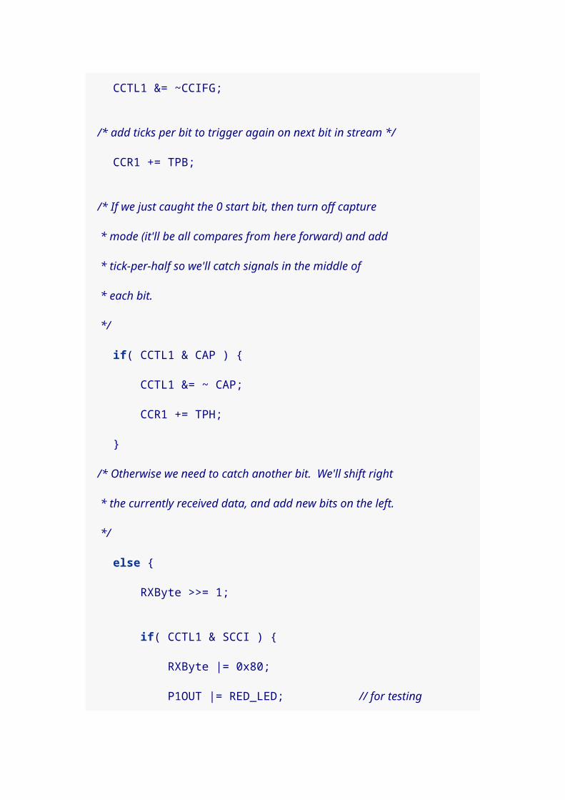
CCTL0 |= OUTMOD2; } TXWord >>= 1; txbitcnt --; }
/* If there are no bits left, load the next byte */ if( !txbitcnt ) { if( bytestosend ) { /* load next byte with stop bit 0x100 and shifted left * to make the start bit */ TXWord = ( 0x100 | *data++ ) << 1; bytestosend --;
/* 1 start bit + 8 data bits + 1 stop bit */ txbitcnt = 10; } else { /* turn off interrupts */ CCTL0 &= ~ CCIE; /* wake up the main program */ __bic_SR_register_on_exit( LPM0_bits ); } }
/* add ticks per bit to trigger again on next bit in stream */ CCR0 += TPB; /* reset the interrupt flag */ CCTL0 &= ~CCIFG;}
/* Prepares a block of data to be sent. */int sendBytes( unsigned char *d, int len ) { /* can't queue up data if we're still sending */ if( bytestosend > 0 ) return 0;
txbitcnt = 0; data = d; bytestosend = len;
/* Make sure we don't catch the TAR register while it is changing. * As long as the difference is only in the lower bits, we'll call * it close enough. */ do {

CCR0 = TAR; } while( (CCR0^TAR) > 3 );
CCR0 += TPB;
/* Timer A0 to start triggering interrupts */ CCTL0 = CCIS0 + OUTMOD0 + CCIE;
/* sleep until message sent */ while( CCTL0 & CCIE ) { __bis_SR_register( LPM0_bits + GIE ); }
return len;}
/* Sends a single byte to the computer */int sendByte( unsigned char b ) { return sendBytes( &b, 1 );}
/* Sends a string of characters to the computer */int sendString( char *str ) { return sendBytes( str, strlen(str) );}
/* A button press triggers this interrupt, which wakes * up the main program to send a message. */void Port_1 (void) __attribute__((interrupt(PORT1_VECTOR)));void Port_1(void) { /* clear interrupt flag */ P1IFG &= ~BUTTON; /* disable button (will be re-enabled in main program) */ P1IE |= BUTTON;
/* wake up the main program */ __bic_SR_register_on_exit( LPM3_bits );}
void report_data( void ) { char str[] = "0x../0x..\r\n";
sendString( "Stock 1Mhz settings BCSCTL1/DCOCTL:" );

str[2] = hex[( CALBC1_1MHZ>>4 ) & 0x0F]; str[3] = hex[( CALBC1_1MHZ>>0 ) & 0x0F]; str[7] = hex[( CALDCO_1MHZ>>4 ) & 0x0F]; str[8] = hex[( CALDCO_1MHZ>>0 ) & 0x0F]; sendString( str ); sendString( "Derived: " ); str[2] = hex[( calbc1_1mhz>>4 ) & 0x0F]; str[3] = hex[( calbc1_1mhz>>0 ) & 0x0F]; str[7] = hex[( caldco_1mhz>>4 ) & 0x0F]; str[8] = hex[( caldco_1mhz>>0 ) & 0x0F]; sendString( str );
sendString( "Stock 8Mhz settings BCSCTL1/DCOCTL:" ); str[2] = hex[( CALBC1_8MHZ>>4 ) & 0x0F]; str[3] = hex[( CALBC1_8MHZ>>0 ) & 0x0F]; str[7] = hex[( CALDCO_8MHZ>>4 ) & 0x0F]; str[8] = hex[( CALDCO_8MHZ>>0 ) & 0x0F]; sendString( str ); sendString( "Derived: " ); str[2] = hex[( calbc1_8mhz>>4 ) & 0x0F]; str[3] = hex[( calbc1_8mhz>>0 ) & 0x0F]; str[7] = hex[( caldco_8mhz>>4 ) & 0x0F]; str[8] = hex[( caldco_8mhz>>0 ) & 0x0F]; sendString( str );
sendString( "Stock 12Mhz settings BCSCTL1/DCOCTL:" ); str[2] = hex[( CALBC1_12MHZ>>4 ) & 0x0F]; str[3] = hex[( CALBC1_12MHZ>>0 ) & 0x0F]; str[7] = hex[( CALDCO_12MHZ>>4 ) & 0x0F]; str[8] = hex[( CALDCO_12MHZ>>0 ) & 0x0F]; sendString( str ); sendString( "Derived: " ); str[2] = hex[( calbc1_12mhz>>4 ) & 0x0F]; str[3] = hex[( calbc1_12mhz>>0 ) & 0x0F]; str[7] = hex[( caldco_12mhz>>4 ) & 0x0F]; str[8] = hex[( caldco_12mhz>>0 ) & 0x0F]; sendString( str );
sendString( "Stock 16Mhz settings BCSCTL1/DCOCTL:" ); str[2] = hex[( CALBC1_16MHZ>>4 ) & 0x0F]; str[3] = hex[( CALBC1_16MHZ>>0 ) & 0x0F]; str[7] = hex[( CALDCO_16MHZ>>4 ) & 0x0F]; str[8] = hex[( CALDCO_16MHZ>>0 ) & 0x0F]; sendString( str );

sendString( "Derived: " ); str[2] = hex[( calbc1_16mhz>>4 ) & 0x0F]; str[3] = hex[( calbc1_16mhz>>0 ) & 0x0F]; str[7] = hex[( caldco_16mhz>>4 ) & 0x0F]; str[8] = hex[( caldco_16mhz>>0 ) & 0x0F]; sendString( str );}
22. Dissecting the TI temperature demo
I’ve started re-implementing the TI temperature demo, both
to make it compile with mspgcc4, and to enhance and
embellish the comments in the code. Hopefully, beginners
will find it easier to understand with more copious
comments, especially if they can see it implemented bit by
bit.
It’s sort of a long process, so I’ve devoted a separate page
to it: demo.html
MSP430 Launchpad Demo ProgramDon Bindner<[email protected]>Table of Contents
1. Startup mode
2. Entering Application Mode
3. Communication With the Computer

4. Internal temperature sensorPersonally, I found the TI MSP430 Launchpad demo code a little daunting on first read. It’s easier and more readable than a lot of the demo code I’ve found for the MSP430, but I bet there are a lot of people who still find it difficult. I decided I would devote a page to building up the TI demo part by part in such a way that a beginner could watch the it being created.This code is for the MSP430g2231 chip with the internal temperature sensor.This page is a companion page for my MSP430 Launchpad page.
1. Startup modeWhen the MSP430 powers up, it blinks the LEDs to let the user know that the device is alive. The key functions are PreApplicationMode() which sets up Timer A1 to generate an interrupt every 1/5 second, and t1a_isr() which handles the interrupt and toggles the LEDs. The chip spends almost all of its time sleeping in low power mode 3 (which is entered right at the end of PreApplicationMode()).#include <msp430x20x2.h>
#define RED_LED BIT0#define GRN_LED BIT6
#define APP_STANDBY_MODE 0#define APP_APPLICATION_MODE 1
unsigned char applicationMode = APP_STANDBY_MODE;
/* the mode the chip initially enters to blink the LEDs */void PreApplicationMode(void) { /* Set both LED pins as output pins and turn red on, green off */ P1DIR |= RED_LED + GRN_LED; P1OUT |= RED_LED; P1OUT &= ~GRN_LED;
/* The basic clock system control register 3 controls the oscillator * the auxilliary clock uses. Change ACLK from external timer crystal * oscillator to internal very low-power oscillator (VLO) clock, * which runs at appoximately 12kHz. */
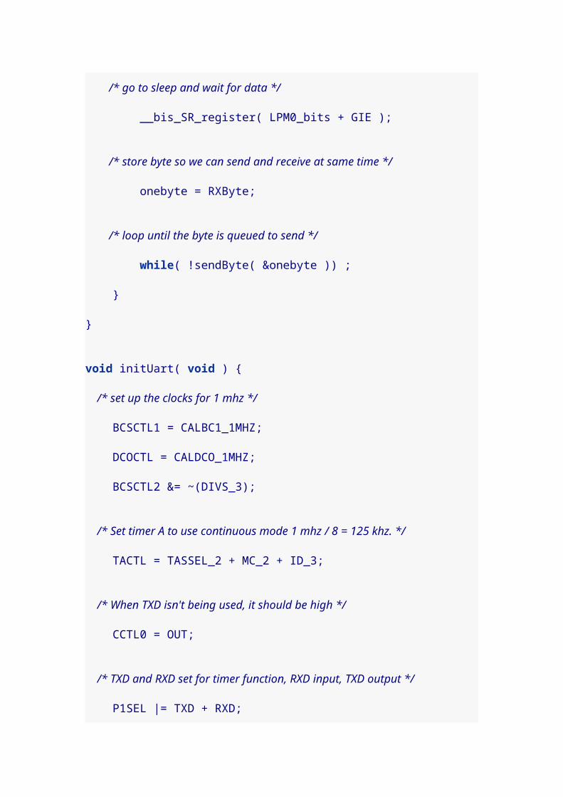
BCSCTL3 |= LFXT1S_2;
/* Basic clock system control register 1 controls the auxilliary clock * divider. Set ACLK to use Divider 1, i.e. divided by 2^1. */ BCSCTL1 |= DIVA_1;
/* Set TimerA counter period to 1200 or about 1/5 second */ TACCR0 = 1200; /* Set TimerA to use auxilliary clock TASSEL_1 and count up mode MC_1 */ TACTL = TASSEL_1 | MC_1; /* Set capture/compare mode interrupts enabled, to trigger an interrupt * when TACCR1 is reached. OUTMOD_3 not essential here? */ TACCTL1 = CCIE + OUTMOD_3; /* The value at which TimerA1 interrupt triggers. */ TACCR1 = 600;
/* Go to sleep in low power mode 3 with interrupts enabled. */ __bis_SR_register(LPM3_bits + GIE);}
/* Timer A interrupt service routine 1. The function prototype * tells the compiler that this will service the Timer A1 interrupt, * and then the function follows. */void ta1_isr(void) __attribute__((interrupt(TIMERA1_VECTOR)));void ta1_isr(void){ /* clear the interrupt flag */ TACCTL1 &= ~CCIFG;
/* in application mode, we'll turn off the LEDs, otherwise we'll * toggle them. */ if (applicationMode == APP_APPLICATION_MODE) P1OUT &= ~(RED_LED + GRN_LED); else P1OUT ^= (RED_LED + GRN_LED);
}
/************** main program begins here ***************/

void main( void ) { /* access the watchdog timer control without password and hold * the count (so the watchdog timer doesn't reset the chip) */ WDTCTL = WDTPW + WDTHOLD;
PreApplicationMode();}
2. Entering Application ModeThis version adds a way to get into the application mode of the program by pressing switch 2. Because of the check in ta1_isr() this will cause the LEDs to go dark. The key new functions are InitializeButton() which configures the button to trigger interrupts, PORT1_ISR() which is triggered by button presses, andWDT_ISR() which is used to handle button bounce in software.Debouncing is handled in a very clever way. When the button interrupt is triggered, that service handler disables future button interrupts to prevent spurious extra "bounce presses." It then sets the Watchdog timer to wait one quarter second and execute the timer Watchdog interrupt. The Watchdog interrupt service handler then turns the button interrupts back on.The neat thing is that the program doesn’t have to stop or delay for any of this to work. In effect we just schedule the button to start working again 681 milliseconds in the future and an interrupt will fire automatically when the time comes to make that happen.#include <msp430x20x2.h>
#define RED_LED BIT0#define GRN_LED BIT6
#define BUTTON BIT3
#define APP_STANDBY_MODE 0#define APP_APPLICATION_MODE 1
unsigned char applicationMode = APP_STANDBY_MODE;
/* the mode the chip initially enters to blink the LEDs */void PreApplicationMode(void) { /* Set both LED pins as output pins and turn red on, green off */ P1DIR |= RED_LED + GRN_LED;

P1OUT |= RED_LED; P1OUT &= ~GRN_LED;
/* The basic clock system control register 3 controls the oscillator * the auxilliary clock uses. Change ACLK from external timer crystal * oscillator to internal very low-power oscillator (VLO) clock, * which runs at appoximately 12kHz. */ BCSCTL3 |= LFXT1S_2;
/* Basic clock system control register 1 controls the auxilliary clock * divider. Set ACLK to use Divider 1, i.e. divided by 2^1. */ BCSCTL1 |= DIVA_1;
/* Set TimerA counter period to 1200 or about 1/5 second */ TACCR0 = 1200; /* Set TimerA to use auxilliary clock TASSEL_1 and count up mode MC_1 */ TACTL = TASSEL_1 | MC_1; /* Set capture/compare mode interrupts enabled, to trigger an interrupt * when TACCR1 is reached. OUTMOD_3 not essential here? */ TACCTL1 = CCIE + OUTMOD_3; /* The value at which TimerA1 interrupt triggers. */ TACCR1 = 600;
/* Go to sleep in low power mode 3 with interrupts enabled. */ __bis_SR_register(LPM3_bits + GIE);}
/* Timer A interrupt service routine 1. The function prototype * tells the compiler that this will service the Timer A1 interrupt, * and then the function follows. */void ta1_isr(void) __attribute__((interrupt(TIMERA1_VECTOR)));void ta1_isr(void){ /* clear the interrupt flag */ TACCTL1 &= ~CCIFG;
/* in application mode, we'll turn off the LEDs, otherwise we'll * toggle them.

*/ if (applicationMode == APP_APPLICATION_MODE) P1OUT &= ~(RED_LED + GRN_LED); else P1OUT ^= (RED_LED + GRN_LED);
}
/* This function configures the button so it will trigger interrupts * when pressed. Those interrupts will be handled by PORT1_ISR() */void InitializeButton(void) { /* Set button pin as an input pin */ P1DIR &= ~BUTTON; /* set pull up resistor on for button */ P1OUT |= BUTTON; /* enable pull up resistor for button to keep pin high until pressed */ P1REN |= BUTTON; /* Interrupt should trigger from high (unpressed) to low (pressed) */ P1IES |= BUTTON; /* Clear the interrupt flag for the button */ P1IFG &= ~BUTTON; /* Enable interrupts on port 1 for the button */ P1IE |= BUTTON;}
/* ************************************************************* * Port Interrupt for Button Press * 1. During standby mode: to exit and enter application mode * 2. During application mode: to recalibrate temp sensor * *********************************************************** */void PORT1_ISR(void) __attribute__((interrupt(PORT1_VECTOR)));void PORT1_ISR(void){ /* clear interrupt flag for port 1 */ P1IFG = 0; /* disable interrupts for the button to handle button bounce */ P1IE &= ~BUTTON; /* set watchdog timer to trigger every 681 milliseconds -- normally * this would be 250 ms, but the VLO is slower */ WDTCTL = WDT_ADLY_250;

/* clear watchdog timer interrupt flag */ IFG1 &= ~WDTIFG; /* enable watchdog timer interrupts; in 681 ms the button * will be re-enabled by WDT_ISR() -- program will continue in * the meantime. */ IE1 |= WDTIE;
if (applicationMode == APP_APPLICATION_MODE) { // tempCalibrated = tempAverage; // calibrateUpdate = 1; } else { /* switch to APPLICATION MODE */ applicationMode = APP_APPLICATION_MODE; /* clear the low power mode bit, so when we return from * the interrupt call, the program will resume running */ __bic_SR_register_on_exit(LPM3_bits); }}
/* This function catches watchdog timer interrupts, which are * set to happen 681ms after the user presses the button. The * button has had time to "bounce" and we can turn the button * interrupts back on. */void WDT_ISR(void) __attribute__((interrupt(WDT_VECTOR)));void WDT_ISR(void){ /* Disable interrupts on the watchdog timer */ IE1 &= ~WDTIE; /* clear the interrupt flag for watchdog timer */ IFG1 &= ~WDTIFG; /* resume holding the watchdog timer so it doesn't reset the chip */ WDTCTL = WDTPW + WDTHOLD; /* and re-enable interrupts for the button */ P1IE |= BUTTON;}
/************** main program begins here ***************/void main( void ) { /* access the watchdog timer control without password and hold

* the count (so the watchdog timer doesn't reset the chip) */ WDTCTL = WDTPW + WDTHOLD;
InitializeButton(); PreApplicationMode();}
3. Communication With the ComputerThe MSP430 doesn’t just blink lights in this demo. It also communicates the internal chip temperature back to the computer. We haven’t yet written any code to measure temperature, but we can frame in the code for communicating with the computer.After the clock oscillators are calibrated with InitializeClocks(), communication is handled by three functions: ConfigureTimerUart() which setups up TimerA0,Transmit() which queues up a particular transmission, and Timer_A() which actually does the communication.#include <msp430x20x2.h>
#define RED_LED BIT0#define GRN_LED BIT6#define TXD BIT1#define RXD BIT2
#define BUTTON BIT3
#define APP_STANDBY_MODE 0#define APP_APPLICATION_MODE 1
#define TIMER_PWM_MODE 0#define TIMER_UART_MODE 1#define TIMER_PWM_PERIOD 2000#define TIMER_PWM_OFFSET 20
/* Conditions for 2400 Baud SW UART, SMCLK = 1MHz, divider 8 * (1 Mhz/8) / 2400 bps = 52 clock cycles per bit */#define Bitime_5 20 // ~ clock ticks per half bit#define Bitime 52 // clock ticks per bit#define UART_UPDATE_INTERVAL 1000

unsigned char BitCnt;unsigned int TXByte;
unsigned char applicationMode = APP_STANDBY_MODE;
unsigned char timerMode = TIMER_PWM_MODE;
/* the mode the chip initially enters to blink the LEDs */void PreApplicationMode(void) { /* Set both LED pins as output pins and turn red on, green off */ P1DIR |= RED_LED + GRN_LED; P1OUT |= RED_LED; P1OUT &= ~GRN_LED;
/* The basic clock system control register 3 controls the oscillator * the auxilliary clock uses. Change ACLK from external timer crystal * oscillator to internal very low-power oscillator (VLO) clock, * which runs at appoximately 12kHz. */ BCSCTL3 |= LFXT1S_2;
/* Basic clock system control register 1 controls the auxilliary clock * divider. Set ACLK to use Divider 1, i.e. divided by 2^1. */ BCSCTL1 |= DIVA_1;
/* Set TimerA counter period to 1200 or about 1/5 second */ TACCR0 = 1200; /* Set TimerA to use auxilliary clock TASSEL_1 and count up mode MC_1 */ TACTL = TASSEL_1 | MC_1; /* Set capture/compare mode interrupts enabled, to trigger an interrupt * when TACCR1 is reached. OUTMOD_3 not essential here? */ TACCTL1 = CCIE + OUTMOD_3; /* The value at which TimerA1 interrupt triggers. */ TACCR1 = 600;
/* Go to sleep in low power mode 3 with interrupts enabled. */ __bis_SR_register(LPM3_bits + GIE);}

void InitializeClocks(void) { /* Use calibration values to set digitally controlled oscillator * to 1 mhz, and set the submain clock to the same (i.e. we turn * off the /8 divider bit). */ BCSCTL1 = CALBC1_1MHZ; DCOCTL = CALDCO_1MHZ; BCSCTL2 &= ~(DIVS_3);}
void ConfigureTimerPwm(void) { timerMode = TIMER_PWM_MODE;
TACCR0 = TIMER_PWM_PERIOD; // TACTL = TASSEL_2 | MC_1; // TACLK = SMCLK, Up mode. TACCTL0 = CCIE; TACCTL1 = CCIE + OUTMOD_3; // TACCTL1 Capture Compare TACCR1 = 1;}
void ConfigureTimerUart(void) { /* This flag tells us that we're using the timer for communcation * rather than pulse width modulation. */ timerMode = TIMER_UART_MODE;
/* Set transmission pin high for now (until we later set it low * to start communication). */ CCTL0 = OUT;
/* TimerA is using submain clock (at 1mhz), in continuous mode, * with a clock divider of 2^3=8 */ TACTL = TASSEL_2 + MC_2 + ID_3;
/* Set transmit and receive pins latched to the timer, and the * transmit pin is set as an output pin. */ P1SEL |= TXD + RXD; P1DIR |= TXD;}

void Transmit() { /* Function Transmits Character from TXByte. We'll have 10 bits total * to communicate, 8 bits of data plus a start bit (zero) and a * stop bit (one). */ BitCnt = 10;
/* Make sure we don't catch the TAR register while it is changing. * As long as the difference is only in the lower bits, we'll call * it close enough. */ do { CCR0 = TAR; } while( (CCR0^TAR) > 3 );
/* Set time when the transmission will actually begin */ CCR0 += Bitime; /* Add a one bit to act as stop bit (least significant bits in the TXByte get sent first) */ TXByte |= 0x100; /* Shift left to make an initial zero bit to act as start bit */ TXByte = TXByte << 1;
/* Timer A0 to start triggering interrupts to do the actual sending */ CCTL0 = CCIS0 + OUTMOD0 + CCIE;
/* We'll loop and wait for the transmission to finish */ while ( CCTL0 & CCIE ) ;}
// Timer A0 interrupt service routinevoid Timer_A(void) __attribute__((interrupt(TIMERA0_VECTOR)));void Timer_A(void) { if (timerMode == TIMER_UART_MODE) { /* schedule when the next bit is communicated */ CCR0 += Bitime;
/* If the transmission bit is set */ if (CCTL0 & CCIS0) { /* Are there bits left to be transmitted? */ if ( BitCnt == 0) {

/* No, disable the interrupt. We're done. */ CCTL0 &= ~ CCIE; } else { /* If the next bit is a one, set pin high/mark */ if (TXByte & 0x01) { CCTL0 &= ~ OUTMOD2; } else {/* Otherwise set pin low/space */ CCTL0 |= OUTMOD2; }
/* Shift right to drop the bit we just sent, and update the count. */ TXByte = TXByte >> 1; BitCnt --; } } } else {// if (tempPolarity == TEMP_HOT)// LED_OUT |= LED1;// if (tempPolarity == TEMP_COLD)// LED_OUT |= LED0;
} /* Clear the interrupt flag */ TACCTL0 &= ~CCIFG;}
/* Timer A interrupt service routine 1. The function prototype * tells the compiler that this will service the Timer A1 interrupt, * and then the function follows. */void ta1_isr(void) __attribute__((interrupt(TIMERA1_VECTOR)));void ta1_isr(void){ /* clear the interrupt flag */ TACCTL1 &= ~CCIFG;
/* in application mode, we'll turn off the LEDs, otherwise we'll * toggle them. */ if (applicationMode == APP_APPLICATION_MODE) { P1OUT &= ~(RED_LED + GRN_LED); } else {

P1OUT ^= (RED_LED + GRN_LED); }}
/* This function configures the button so it will trigger interrupts * when pressed. Those interrupts will be handled by PORT1_ISR() */void InitializeButton(void) { /* Set button pin as an input pin */ P1DIR &= ~BUTTON; /* set pull up resistor on for button */ P1OUT |= BUTTON; /* enable pull up resistor for button to keep pin high until pressed */ P1REN |= BUTTON; /* Interrupt should trigger from high (unpressed) to low (pressed) */ P1IES |= BUTTON; /* Clear the interrupt flag for the button */ P1IFG &= ~BUTTON; /* Enable interrupts on port 1 for the button */ P1IE |= BUTTON;}
/* ************************************************************* * Port Interrupt for Button Press * 1. During standby mode: to exit and enter application mode * 2. During application mode: to recalibrate temp sensor * *********************************************************** */void PORT1_ISR(void) __attribute__((interrupt(PORT1_VECTOR)));void PORT1_ISR(void){ /* clear interrupt flag for port 1 */ P1IFG = 0; /* disable interrupts for the button to handle button bounce */ P1IE &= ~BUTTON; /* set watchdog timer to trigger every 681 milliseconds -- normally * this would be 250 ms, but the VLO is slower */ WDTCTL = WDT_ADLY_250; /* clear watchdog timer interrupt flag */ IFG1 &= ~WDTIFG; /* enable watchdog timer interrupts; in 681 ms the button * will be re-enabled by WDT_ISR() -- program will continue in

* the meantime. */ IE1 |= WDTIE;
if (applicationMode == APP_APPLICATION_MODE) { // tempCalibrated = tempAverage; // calibrateUpdate = 1; } else { /* switch to APPLICATION MODE */ applicationMode = APP_APPLICATION_MODE; /* clear the low power mode bit, so when we return from * the interrupt call, the program will resume running */ __bic_SR_register_on_exit(LPM3_bits); }}
/* This function catches watchdog timer interrupts, which are * set to happen 681ms after the user presses the button. The * button has had time to "bounce" and we can turn the button * interrupts back on. */void WDT_ISR(void) __attribute__((interrupt(WDT_VECTOR)));void WDT_ISR(void){ /* Disable interrupts on the watchdog timer */ IE1 &= ~WDTIE; /* clear the interrupt flag for watchdog timer */ IFG1 &= ~WDTIFG; /* resume holding the watchdog timer so it doesn't reset the chip */ WDTCTL = WDTPW + WDTHOLD; /* and re-enable interrupts for the button */ P1IE |= BUTTON;}
/************** main program begins here ***************/void main( void ) { /* access the watchdog timer control without password and hold * the count (so the watchdog timer doesn't reset the chip) */ WDTCTL = WDTPW + WDTHOLD;

InitializeClocks(); InitializeButton(); PreApplicationMode();
/* application mode begins */ applicationMode = APP_APPLICATION_MODE;
ConfigureTimerPwm();
for( ; ; ) { ConfigureTimerUart(); TXByte = '.'; // for testing Transmit(); }}To use this program, I typed:$ mspdebug rf2500 exit ; minicom -b 2400 -o -D /dev/ttyACM0Pressing Switch 2 shows me a series of dots, i.e. period characters. The reset button on the Launchpad stops it.
4. Internal temperature sensorThis code contains two new functions, ConfigureAdcTempSensor() and ADC10_ISR(). The first function configures the analogue to digital converter to use the internal temperature sensor and takes a reading. It’s important to know that ADC conversions are not instantaneous. Effectively, you have to schedule a temperature reading and then wait for it to occur. That’s what the ADC10_ISR() function is for. It responds to the interrupt that occurs when a new value is ready and wakes up the main program.Eventually, the program will keep a history of temperature values so it can compute a moving average, but for now we just read in a single value and use ourTransmit() code to send it back as a byte to the PC. If your room is a reasonable temperature (at least 65F) you should see upper case letters.#include <msp430x20x2.h>
#define RED_LED BIT0#define GRN_LED BIT6#define TXD BIT1#define RXD BIT2

#define BUTTON BIT3
#define APP_STANDBY_MODE 0#define APP_APPLICATION_MODE 1
#define TIMER_PWM_MODE 0#define TIMER_UART_MODE 1#define TIMER_PWM_PERIOD 2000#define TIMER_PWM_OFFSET 20
/* Conditions for 2400 Baud SW UART, SMCLK = 1MHz, divider 8 * (1 Mhz/8) / 2400 bps = 52 clock cycles per bit */#define Bitime_5 20 // ~ clock ticks per half bit#define Bitime 52 // clock ticks per bit#define UART_UPDATE_INTERVAL 1000
unsigned char BitCnt;unsigned int TXByte;
/* We'll keep a history of 8 temperature measurements from the ADC * and calculate a moving average. */long tempMeasured[8];unsigned char tempMeasuredPosition=0;long tempAverage;
long tempCalibrated, tempDifference;
unsigned char applicationMode = APP_STANDBY_MODE;
unsigned char timerMode = TIMER_PWM_MODE;
/* the mode the chip initially enters to blink the LEDs */void PreApplicationMode(void) { /* Set both LED pins as output pins and turn red on, green off */ P1DIR |= RED_LED + GRN_LED; P1OUT |= RED_LED; P1OUT &= ~GRN_LED;
/* The basic clock system control register 3 controls the oscillator

* the auxilliary clock uses. Change ACLK from external timer crystal * oscillator to internal very low-power oscillator (VLO) clock, * which runs at appoximately 12kHz. */ BCSCTL3 |= LFXT1S_2;
/* Basic clock system control register 1 controls the auxilliary clock * divider. Set ACLK to use Divider 1, i.e. divided by 2^1. */ BCSCTL1 |= DIVA_1;
/* Set TimerA counter period to 1200 or about 1/5 second */ TACCR0 = 1200; /* Set TimerA to use auxilliary clock TASSEL_1 and count up mode MC_1 */ TACTL = TASSEL_1 | MC_1; /* Set capture/compare mode interrupts enabled, to trigger an interrupt * when TACCR1 is reached. OUTMOD_3 not essential here? */ TACCTL1 = CCIE + OUTMOD_3; /* The value at which TimerA1 interrupt triggers. */ TACCR1 = 600;
/* Go to sleep in low power mode 3 with interrupts enabled. */ __bis_SR_register(LPM3_bits + GIE);}
void ConfigureAdcTempSensor(void) { volatile unsigned int i; /* Configure ADC input channel 10 (i.e. the temperature sensor) * with clock divider /4 */ ADC10CTL1 = INCH_10 + ADC10DIV_3;
/* not sure what these mean */ ADC10CTL0 = SREF_1 + ADC10SHT_3 + REFON + ADC10ON + ADC10IE;
/* A delay loop for ADC reference to settle */ for( i = 0; i < 500; i++ ) ;
/* Enable ADC conversion and set it to start conversion */ ADC10CTL0 |= ENC + ADC10SC;

/* Sleep in LPM0 until the conversion is ready */ __bis_SR_register(LPM0_bits + GIE); /* Read off the temperature raw value */ tempCalibrated = ADC10MEM;
/* We'll keep a history of temperatures to compute a moving average, * but for now they're all initialized to this starting temp. So * is the average temperature. */ for (i=0; i < 8; i++) tempMeasured[i] = tempCalibrated; tempAverage = tempCalibrated;}
void InitializeClocks(void) { /* Use calibration values to set digitally controlled oscillator * to 1 mhz, and set the submain clock to the same (i.e. we turn * off the /8 divider bit). */ BCSCTL1 = CALBC1_1MHZ; DCOCTL = CALDCO_1MHZ; BCSCTL2 &= ~(DIVS_3);}
void ConfigureTimerPwm(void) { timerMode = TIMER_PWM_MODE;
TACCR0 = TIMER_PWM_PERIOD; // TACTL = TASSEL_2 | MC_1; // TACLK = SMCLK, Up mode. TACCTL0 = CCIE; TACCTL1 = CCIE + OUTMOD_3; // TACCTL1 Capture Compare TACCR1 = 1;}
void ConfigureTimerUart(void) { /* This flag tells us that we're using the timer for communcation * rather than pulse width modulation. */ timerMode = TIMER_UART_MODE;

/* Set transmission pin high for now (until we later set it low * to start communication). */ CCTL0 = OUT;
/* TimerA is using submain clock (at 1mhz), in continuous mode, * with a clock divider of 2^3=8 */ TACTL = TASSEL_2 + MC_2 + ID_3;
/* Set transmit and receive pins latched to the timer, and the * transmit pin is set as an output pin. */ P1SEL |= TXD + RXD; P1DIR |= TXD;}
void Transmit() { /* Function Transmits Character from TXByte. We'll have 10 bits total * to communicate, 8 bits of data plus a start bit (zero) and a * stop bit (one). */ BitCnt = 10;
/* Make sure we don't catch the TAR register while it is changing. * As long as the difference is only in the lower bits, we'll call * it close enough. */ do { CCR0 = TAR; } while( (CCR0^TAR) > 3 );
/* Set time when the transmission will actually begin */ CCR0 += Bitime; /* Add a one bit to act as stop bit (least significant bits in the TXByte get sent first) */ TXByte |= 0x100; /* Shift left to make an initial zero bit to act as start bit */ TXByte = TXByte << 1;
/* Timer A0 to start triggering interrupts to do the actual sending */ CCTL0 = CCIS0 + OUTMOD0 + CCIE;

/* We'll loop and wait for the transmission to finish */ while ( CCTL0 & CCIE ) ;}
// Timer A0 interrupt service routinevoid Timer_A(void) __attribute__((interrupt(TIMERA0_VECTOR)));void Timer_A(void) { if (timerMode == TIMER_UART_MODE) { /* schedule when the next bit is communicated */ CCR0 += Bitime;
/* If the transmission bit is set */ if (CCTL0 & CCIS0) { /* Are there bits left to be transmitted? */ if ( BitCnt == 0) { /* No, disable the interrupt. We're done. */ CCTL0 &= ~ CCIE; } else { /* If the next bit is a one, set pin high/mark */ if (TXByte & 0x01) { CCTL0 &= ~ OUTMOD2; } else {/* Otherwise set pin low/space */ CCTL0 |= OUTMOD2; }
/* Shift right to drop the bit we just sent, and update the count. */ TXByte = TXByte >> 1; BitCnt --; } } } else {// if (tempPolarity == TEMP_HOT)// LED_OUT |= LED1;// if (tempPolarity == TEMP_COLD)// LED_OUT |= LED0;
} /* Clear the interrupt flag */ TACCTL0 &= ~CCIFG;}
/* Timer A interrupt service routine 1. The function prototype

* tells the compiler that this will service the Timer A1 interrupt, * and then the function follows. */void ta1_isr(void) __attribute__((interrupt(TIMERA1_VECTOR)));void ta1_isr(void){ /* clear the interrupt flag */ TACCTL1 &= ~CCIFG;
/* in application mode, we'll turn off the LEDs, otherwise we'll * toggle them. */ if (applicationMode == APP_APPLICATION_MODE) { P1OUT &= ~(RED_LED + GRN_LED); } else { P1OUT ^= (RED_LED + GRN_LED); }}
/* This function configures the button so it will trigger interrupts * when pressed. Those interrupts will be handled by PORT1_ISR() */void InitializeButton(void) { /* Set button pin as an input pin */ P1DIR &= ~BUTTON; /* set pull up resistor on for button */ P1OUT |= BUTTON; /* enable pull up resistor for button to keep pin high until pressed */ P1REN |= BUTTON; /* Interrupt should trigger from high (unpressed) to low (pressed) */ P1IES |= BUTTON; /* Clear the interrupt flag for the button */ P1IFG &= ~BUTTON; /* Enable interrupts on port 1 for the button */ P1IE |= BUTTON;}
/* ************************************************************* * Port Interrupt for Button Press * 1. During standby mode: to exit and enter application mode * 2. During application mode: to recalibrate temp sensor * *********************************************************** */void PORT1_ISR(void) __attribute__((interrupt(PORT1_VECTOR)));

void PORT1_ISR(void){ /* clear interrupt flag for port 1 */ P1IFG = 0; /* disable interrupts for the button to handle button bounce */ P1IE &= ~BUTTON; /* set watchdog timer to trigger every 681 milliseconds -- normally * this would be 250 ms, but the VLO is slower */ WDTCTL = WDT_ADLY_250; /* clear watchdog timer interrupt flag */ IFG1 &= ~WDTIFG; /* enable watchdog timer interrupts; in 681 ms the button * will be re-enabled by WDT_ISR() -- program will continue in * the meantime. */ IE1 |= WDTIE;
if (applicationMode == APP_APPLICATION_MODE) { // tempCalibrated = tempAverage; // calibrateUpdate = 1; } else { /* switch to APPLICATION MODE */ applicationMode = APP_APPLICATION_MODE; /* clear the low power mode bit, so when we return from * the interrupt call, the program will resume running */ __bic_SR_register_on_exit(LPM3_bits); }}
/* This function catches watchdog timer interrupts, which are * set to happen 681ms after the user presses the button. The * button has had time to "bounce" and we can turn the button * interrupts back on. */void WDT_ISR(void) __attribute__((interrupt(WDT_VECTOR)));void WDT_ISR(void){ /* Disable interrupts on the watchdog timer */ IE1 &= ~WDTIE; /* clear the interrupt flag for watchdog timer */ IFG1 &= ~WDTIFG;
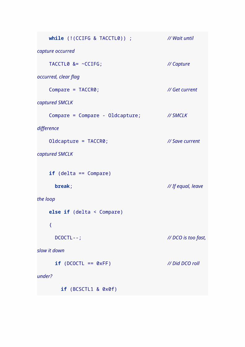
/* resume holding the watchdog timer so it doesn't reset the chip */ WDTCTL = WDTPW + WDTHOLD; /* and re-enable interrupts for the button */ P1IE |= BUTTON;}
/* This function catches interrupts from the analogue to digital * controller (ADC), which fire after a temperature has been sampled. * Each time we sample, we sleep until ready, so all this routine * has to do is wake the program back up. */void ADC10_ISR(void) __attribute__((interrupt(ADC10_VECTOR)));void ADC10_ISR(void){ __bic_SR_register_on_exit(LPM0_bits);}
/************** main program begins here ***************/void main( void ) { /* access the watchdog timer control without password and hold * the count (so the watchdog timer doesn't reset the chip) */ WDTCTL = WDTPW + WDTHOLD;
InitializeClocks(); InitializeButton(); PreApplicationMode();
/* application mode begins */ applicationMode = APP_APPLICATION_MODE; ConfigureAdcTempSensor();
ConfigureTimerPwm();
for( ; ; ) { ConfigureTimerUart();
/* This conversion formula is magic! */ TXByte = (unsigned char)( ((tempAverage - 630) * 761) / 1024 );
Transmit();

}}To use this program, I typed:$ mspdebug rf2500 exit ; minicom -b 2400 -o -D /dev/ttyACM0Pressing Switch 2 shows me a series of C characters because my room is 67F. The reset button on the Launchpad stops it.Return to MSP430 Launchpad page.Last updated 2011-04-08 23:37:29 CDT
23. Bit-bang I2C interface for Newhaven LCD panel
I wanted to use an LCD panel that does I2C communication
(and that means I needed to learn about I2C). So I decided
to write a bit-bang I2C master program for my Launchpad
to display messages on my Newhaven C0220BIZ-FS(RGB)-
FBW-3VM LCD panel.
I’m not sure how detailed I intend to be, so I’ve broken the
experiment out into its own page: lcd_i2c.html
I2C communications with Newhaven LCD PanelDon Bindner<[email protected]>

Table of Contents
1. I2C communications
2. Wiring up the LCD panel
3. A first I2C program3.1. I2C discussion3.2. LCD panel functions3.3. LCD contrast
4. I2C Multi-master
5. A multi-master I2C bit-banger
6. Messages in memory6.1. Adding a memory chip6.2. LCD changes6.3. I2C changes
7. Capacitive Touch
This page is a companion page for my MSP430
Launchpad page.
As part of a project with a student, I wanted to get my
MSP430 to talk to a relatively inexpensive LCD panel. I
chose the Newhaven C0220BIZ-FS(RGB)-FBW-3VM panel,
which communicates via an I2C interface. It is a 3.3v part
(except the red backlight which wants less), which makes it
a natural fit for the MSP430.
We bought our Newhaven displays from Jameco for $11.95
each: Item # 2118539 You may want to pick up at least one

1uF capacitor, and three 10K ohm resistors at the same
time (two for the I2C lines, and one for the reset pin).

The pins of the Newhaven LCD are not set at a standard 0.1" (2.54mm) spacing. I had to gently spread the pins apart to fit the LCD to standard perf board. Basically, I angled a few pins into the perf board at one edge, wiggling slightly to bend the pins as I worked more and more into the holes. You also can’t see the fat pins that run the backlight are hanging off the side of the board, since they don’t fit either.
1. I2C communications
The I2C communications protocol is a method of doing
serial communications that overcomes one of the inherent
problems with typical UART serial methods, that of
synchronizing the data rate at both ends. (With standard
serial communications, you have to be careful to set the
same baud rate for the transmitter and receiver, or the
communication will fail.)
Only 2 wires are required for I2C communication (plus the
power and ground connections), a "data" line and a "clock"
line. That is very nice for a microcontroller, like the
MSP430, which has a limited number of I/O pins.
The general idea of the communication is easy to
understand: a master device puts data on the data line one
bit at a time, most significant bit first, and pulses the clock
line. Slave devices read the data bits during the pulses.

Exact timing is not essential because slaves adapt to
whatever speed the master pulses the clock line.
For detailed information about I2C, the Wikipedia page is
very good, http://en.wikipedia.org/wiki/I%C2%B2C. The
data sheet for the LCD panel also has some relatively
simple example code that is a big help. You’ll definitely be
wanting to read the data sheet for details on the panel!
2. Wiring up the LCD panel
When looking at the front of the LCD panel, pin 1 is on the
right and pin 8 is on the left (page 4 of the data sheet shows
the physical diagram). According to the data sheet, you
should connect pins 7 and 8 with a 1uF capacitor. You’ll
also want to connect pin 6 via a 1uF capacitor to ground
(for example, pin 4).
For the code that follows, I made these connections to my
MSP430 Launchpad:
LCD pin 1 (RST) to MSP430 pin 1.3 (the pin that
switch S2 is on).
LCD pin 2 (SCL) to MSP430 pin 1.6 (the pin with the
green LED).
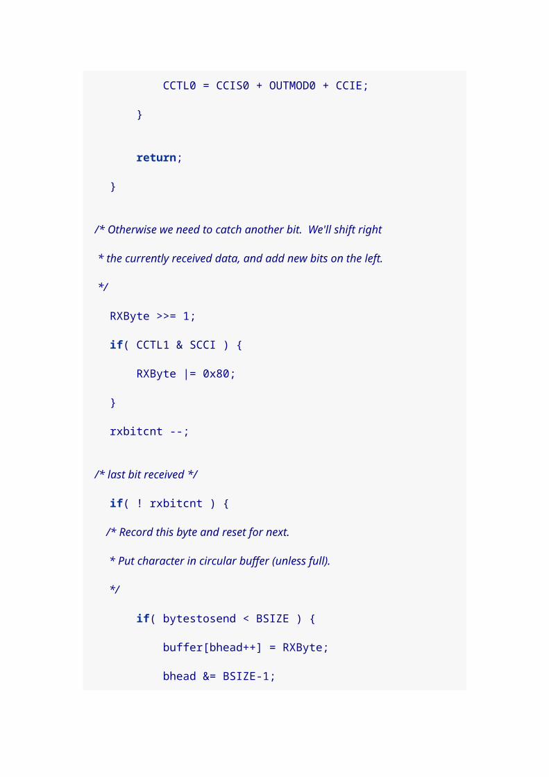
LCD pin 3 (SDA) to MSP430 pin 1.0 (the pin with the
red LED).
LCD pin 4 (VSS) to MSP430 ground.
LCD pin 5 (VDD) to MSP430 Vcc/power.
LCD pins 1, 2, and 3 require pull-up resistors, and two of
these are shown on the data sheet. (The reset pin also
needs to be pulled up since the data sheet describes it as
"active low," and we don’t want the reset button
continuously "pushed" because we forgot to wire it up.
Nothing will work.)
We can use the internal pull-up resistors in the MSP430, so
we won’t need external resistors, but I found physical
resistors to be more reliable. On the Launchpad, switch S2
has a pull-up resistor on it already, so that connection is
covered. But, I connected 10K ohm resistors between
Vcc/power and LCD pins 2 and 3.
Because the clock and data lines are connected to the same pins as the red and green LEDs on the Launchpad, we’ll be able to observe the data communication visually. Later, if we wish, we can remove the jumpers to disconnect the LEDs or switch to different pins on the MSP430.
If you choose instead to modify the code to use the internal pull-up resistors in the MSP430, then you may not be able to watch the LEDs and have the panel actually work at the same time. I had to remove the jumpers (after verifying that the LEDs light up) to get the communication to work.

Since we connected the reset pin of the panel to MSP430 pin 1.3, we can reset the panel as we wish by pressing switch S2. We could also have the microcontroller trigger a reset by outputting a 0 on pin 1.3.
3. A first I2C program#include <msp430g2211.h>
#define I2C_SDA BIT0 // Serial Data line#define I2C_SCL BIT6 // Serial Clock line
/* A crude delay function. Tune by changing the counter value. */void delay( unsigned int n ) { volatile int i;
for( ; n; n-- ) { for( i = 0; i < 50; i++ ); }}
void data_read(void ) { P1DIR &= ~I2C_SDA; // float to get ready to read}
void data_high(void ) { P1DIR &= ~I2C_SDA; // float pin to go high delay( 5 );}
void data_low(void ) { P1OUT &= ~I2C_SDA; // assert low P1DIR |= I2C_SDA; delay( 5 );}
void clk_high(void) { P1DIR &= ~I2C_SCL; // float pin to go high delay( 10 );}
void clk_low(void) {
P1OUT &= ~I2C_SCL; // assert low P1DIR |= I2C_SCL; delay( 5 );}
/* I2C communication starts when both the data and clock * lines go low, in that order. */void I2C_Start(void) { clk_high(); data_high(); data_low(); clk_low();}
/* I2C communication stops with both the clock and data * lines going high, in that order. */void I2C_Stop(void) { data_low(); clk_low(); clk_high(); data_high();}
/* Outputs 8-bit command or data via I2C lines. */void I2C_out(unsigned char d) { int n;
for( n = 0; n < 8; n++ ) { if( d & 0x80 ) { data_high(); } else { data_low(); }
clk_high(); clk_low();
d <<= 1; // Shift next bit into position. }
data_read(); // Set data line to receive. clk_high(); // Clock goes high to wait for acknowledge.

// Slave will pull data line low to acknowledge. while( P1IN & I2C_SDA ) { // Else toggle the clock line and check again clk_low(); clk_high(); }
clk_low();}
/* Initializes the LCD panel. */void init_LCD(void) { I2C_Start();
I2C_out( 0x78 ); // Slave address of the LCD panel. I2C_out( 0x00 ); // Control byte: all following bytes are commands. I2C_out( 0x38 ); // 8-bit bus, 2-line display, normal instruction mode. delay( 10 );
I2C_out( 0x39 ); // 8-bit bus, 2-line display, extension instruction mode. delay( 10 );
I2C_out( 0x14 ); // Bias set to 1/5. I2C_out( 0x78 ); // Contrast set. I2C_out( 0x5E ); // Icon display on, booster on, contrast set. I2C_out( 0x6D ); // Follower circuit on, amplifier=1? I2C_out( 0x0C ); // Display on, cursor off. I2C_out( 0x01 ); // Clear display. I2C_out( 0x06 ); // Entry mode set to cursor-moves-right. delay( 10 );
I2C_Stop();}
/* Sends the "clear display" command to the LCD. */void clear_display(void) { I2C_Start();
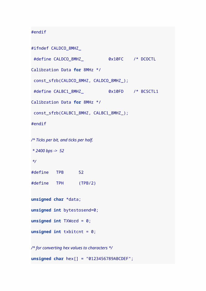
I2C_out( 0x78 ); // Slave address of panel. I2C_out( 0x00 ); // Control byte: all following bytes are commands. I2C_out( 0x01 ); // Clear display.
I2C_Stop();}
/* Writes a 20-char string to the RAM of the LCD. */void show( unsigned char *text ) { int n;
I2C_Start();
I2C_out( 0x78 ); // Slave address of panel. I2C_out( 0x40 ); // Control byte: data bytes follow, data is RAM data.
for( n = 0; n < 20; n++ ) { I2C_out( *text ); text++; }
I2C_Stop();}
int main(void) { int i;
/* Stop the watchdog timer so it doesn't reset our chip */ WDTCTL = WDTPW + WDTHOLD;
init_LCD();
show( "Hello, world. " ); clear_display(); show( "Goodbye, world. " );
__bis_SR_register( LPM3_bits ); /* go to sleep */}
To compile and install:
> msp430-gcc -O2 -mmcu=msp430x2211 -o lcddemo.elf lcddemo.c && mspdebug rf2500 "prog lcddemo.elf"
If you power cycle the Launchpad (and the LCD, since they’re connected) the program will fail initially to communicate with the panel. That is because the Start condition is set by the MSP430 before the panel is ready to detect it. Simply press switch S1 (the Launchpad reset) to restart the program, and everything will work.
3.1. I2C discussion
Most of the program should be relatively easy to
understand. For this first program, we used a crude delay
loop for timing. If you want to slow the timing down,
increase the value of the counter in delay(). This will allow
you to see, and even count if you wish, the communication
bits and the clock pulses on the red and green LEDs of the
Launchpad board.
The data_high() and data_low() functions cause a 1 or 0 to
be put on the data line. Only the 0, however, is an actively
driven value. To put a 1 on the line, we set the pin (which is
pin 1.0) to be an input pin, effectively letting it "float." The
pull-up resistor then takes care of raising the value to 1.
The clk_high() and clk_low() functions work the same way. We either set pin 1.6
as an output pin and put a 0 on it to drive it low, or we set it as an input pin and let it be pulled high.

In this application, with a single master and a single slave, there would be no harm to actively setting the clock line to both 1 and 0. In multi-slave and multi-master situations, we would need to be more careful about our manipulation of the clock line (and the data line too). The Wikipedia page on I2C has more details.
The I2C_Start() function begins each communication.
Slaves will know a communication is beginning when the
data line transitions from high to low while the clock line is
high. (During communication, data line transitions only
occur when the clock line is low.) In I2C_Stop() it is the
transition of the data line from low to high when the clock
line is high that signals the end of the communication.
The I2C_out() function transmits a single 8-bit byte of
values on the data line. Then it waits for an
acknowledgement from the slave device (the LCD panel).
According to the I2C standard, the master should let the
data line float and set the clock line high. When the slave is
ready to continue, it will acknowledge the byte by pulling
the data line low, which will break (or skip) the while loop in
our program.
If your LCD panel is not responding correctly, perhaps because it is miswired or has a different slave address, your program will hang in the while loop. You’ll be able to see this, since the pattern of blinking on the LEDs on the Launchpad will change character (becoming very uniform and continuing forever).

3.2. LCD panel functions
The init_LCD() code is pulled straight from the Newhaven
data sheet, though some comments have been added about
what each byte/command does. It needs to be the first thing
your program communicates to the LCD.
The clear_display() function gives an example of sending a
single command to the LCD.
The show() function copies data sequentially to the RAM of
the panel, and assumes it has been called with strings of
length 20.
The memory configuration of the LCD panel is worth
discussing. This 2-line LCD display has an 80 byte memory
(so more memory than can appear on the display). The first
20 bytes of RAM are the characters that show on the first
line of the 2-line display. The next 20 bytes of RAM exist off-
screen to the right of the first line.
That means that the second line of the display actually fills
RAM location 40-59, which is probably not what you would
naively expect. Finally, at location 60 there are another 20
characters of off-screen data that exists to the right of the
second line.

Here is an example:
clear_display(); show( "Hello, world. " ); // shows on line 1 show( "12345678901234567890" ); // hidden to the right of line 1 show( "Goodbye, world. " ); // shows on line 2 show( "12345678901234567890" ); // hidden to the right of line 2 show( "Oh, hello again. " ); // replaces/shows on line 1
There are commands for scrolling the screen to the left and
right to show the "hidden" off-screen text.
3.3. LCD contrast
My LCD panel had the contrast set too high by default, and
I could not read my hello world text (it looked instead like
two rows of filled black boxes). I found that I could modify
the contrast by placing a resistor between Vout (LCD pin 6)
and Vdd/Vcc (power). I found 3900 ohms to work well. I
have no idea if this is recommended or not, and I plan to
experiment with changing the contrast via commands to the
panel instead. So, perhaps I can remove this resistor.
4. I2C Multi-master
The I2C protocol allows for multiple masters and multiple
slaves to be on the serial bus at once. Each master needs to
watch the bus, so it doesn’t initiate communications while

another master is already active. We can use interrupts to
watch for changes in the data line corresponding to Start
and Stop conditions.
Before writing a fully-fledged multi-master capable
program, we’ll start first with a short program that detects
the start and stop conditions and shows it with LEDs. This
program uses pins 1.4 and 1.5 for the data and clock lines
to leave free pins 1.0 (red LED) and 1.6 (green LED).
#include <msp430g2211.h>
#define I2C_SDA BIT4 // Data line#define I2C_SCL BIT5 // Clock line
/* This flag is set if another master is controlling the bus */int other_master = 0;
/* Catch rising or falling edges of the data line, to check for * Start and Stop condition (and sometimes just other traffic). */void Port_1 (void) __attribute__((interrupt(PORT1_VECTOR)));void Port_1(void) { int status = P1IN;
/* if clock line is high, then this was Start or Stop */ if( status & I2C_SCL ) { /* if data line fell, then this is a Start */ if( ( status & I2C_SDA ) == 0) { other_master = 1; P1OUT |= BIT0; // red on } else { /* this is a Stop */ other_master = 0;

P1OUT &= ~BIT0; // red off } }
if( other_master ) { P1IES &= ~I2C_SDA; /* catch next rising edge */ } else { P1IES |= I2C_SDA; /* catch next falling edge */ }
P1IFG &= ~I2C_SDA; /* clear interrupt flag */}
int main(void) { int i;
/* Stop the watchdog timer so it doesn't reset our chip */ WDTCTL = WDTPW + WDTHOLD;
P1DIR |= BIT0 + BIT6; // status lights are output pins P1OUT &= ~(BIT0 + BIT6); // start off
// Enable interrupts on the data line (dropping edge) P1IES |= I2C_SDA; // dropping edge P1IFG &= ~I2C_SDA; // clear the interrupt flag P1IE |= I2C_SDA; // enable interrupt __bis_SR_register( GIE ); /* general interrupts enabled */
while( 1 ) { /* While we're waiting for interrupts, we'll blink the * green light to show changes in the data line. */ if( P1IN & I2C_SDA ) { P1OUT |= BIT6; /* green on */ } else { P1OUT &= ~BIT6; /* green off */ } }
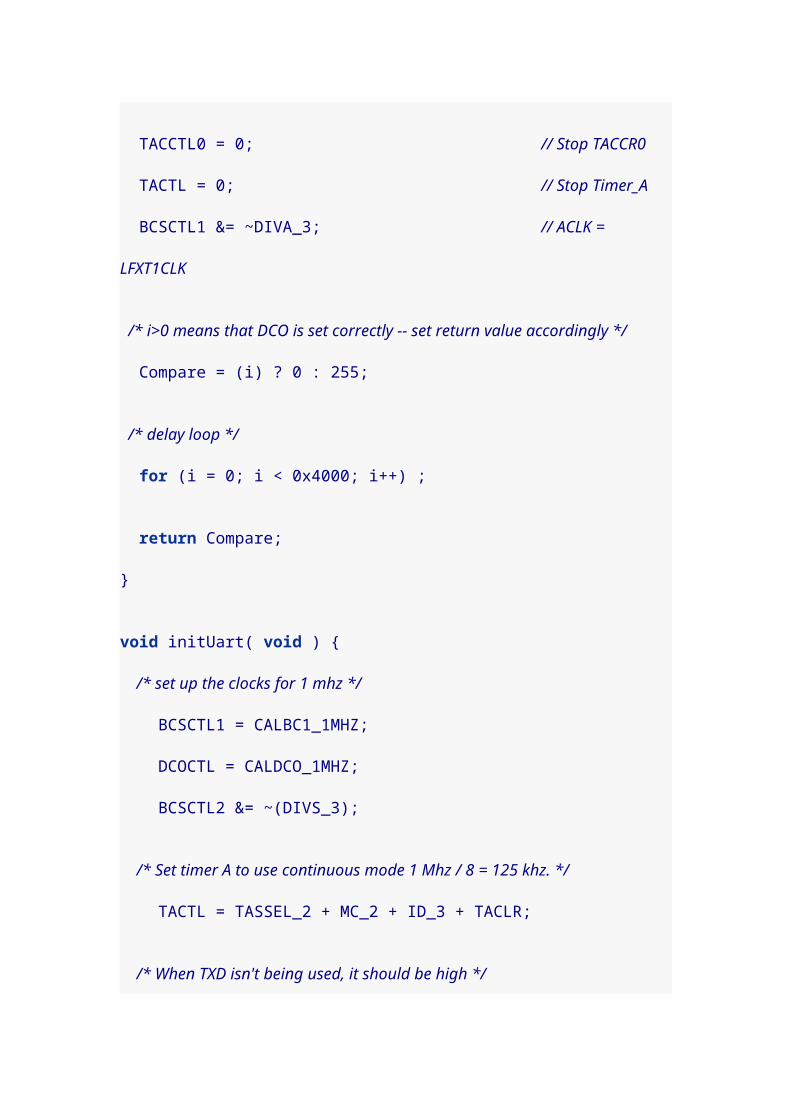
}
Build and install with:
msp430-gcc -O2 -mmcu=msp430x2211 -o i2cmonitor.elf i2cmonitor.c && mspdebug rf2500 "prog i2cmonitor.elf"
5. A multi-master I2C bit-banger
This code implements a multi-master I2C interface via bit-
banging. That is, it is an I2C master that watches the serial
bus for activity from other masters and waits its turn to
communicate. It can also detect when another master starts
communicating simultaneously (and drops out to let the
other master continue).
#include <msp430g2211.h>
#define I2C_SDA BIT4 // Data line#define I2C_SCL BIT5 // Clock line
int other_master = 0;int we_are_master = 0;
/* A crude delay function. Tune by changing the constant. */inline void delay( unsigned int n ) { volatile unsigned int i = n<<2; while( i-- ) ;}
inline void data_read(void ) { P1DIR &= ~I2C_SDA; // float to get ready to read}
inline void data_high(void ) { P1DIR &= ~I2C_SDA; // float pin to go high delay( 5 );

}
inline void data_low(void ) { P1DIR |= I2C_SDA; delay( 5 );}
void clk_high(void) { P1DIR &= ~I2C_SCL; // float pin to go high
int i = 100; while( !(P1IN & I2C_SCL) && i-- ) ; // clock stretching
delay( 10 );}
inline void clk_low(void) { P1DIR |= I2C_SCL; delay( 5 );}
inline int data_pulled_down(void) { return ! (P1IN & I2C_SDA );}
/* Catch rising or falling edges of the data line, to check for * Start and Stop condition (and sometimes just other traffic). */void Port_1 (void) __attribute__((interrupt(PORT1_VECTOR)));void Port_1(void) { int status = P1IN;
/* If both lines are high, we just saw a Stop condition. * Otherwise, another master has the bus. */ if(( status & I2C_SCL ) && (status & I2C_SDA )) { other_master = 0; P1OUT |= BIT6; // green light on P1OUT &= ~BIT0; // red light off P1IES |= I2C_SDA; // catch next fall } else {

other_master = 1; P1OUT &= ~BIT6; // green light off P1IES &= ~I2C_SDA; // catch next rise }
P1IFG &= ~I2C_SDA; /* clear interrupt flag */}
/* If we discover another master on the bus while we are communicating, * we need to abort our communication and watch for Stop condition * before continuing. */inline void lost_arbitration() { other_master = 1;
P1IES &= ~I2C_SDA; // catch next rising edge P1IE |= I2C_SDA; // enable interrupt P1IFG &= ~I2C_SDA; // clear interrupt flag
we_are_master = 0;
P1OUT ^= BIT0+BIT6; // toggle red on and green off}
/* I2C communication starts when both the data and clock * lines go low, in that order. */void I2C_Start(void) { if( other_master ) return;
clk_high(); data_high();
if( data_pulled_down()) { // someone else has the bus lost_arbitration(); return; }
/* stop processing data line interrupts */ P1IE &= ~I2C_SDA;
data_low(); clk_low();

we_are_master = 1;}
/* I2C communication stops with both the clock and data * lines going high, in that order. */void I2C_Stop(void) { if( ! we_are_master ) return;
data_low(); clk_low();
/* Resume watching for Start condition (falling data edge). */ P1IES |= I2C_SDA; P1IE |= I2C_SDA; P1IFG &= ~I2C_SDA;
clk_high(); data_high();
we_are_master = 0;}
/* Outputs 8-bit command or data via I2C lines. */void I2C_out(unsigned char d) { int n;
if( ! we_are_master ) return;
for( n = 0; n < 8; n++ ) { if( d & 0x80 ) { data_high(); clk_high();
/* If the line is 0, some other master is * controlling the line, and we should drop out. */ if( data_pulled_down()) { lost_arbitration(); return; } } else { data_low();
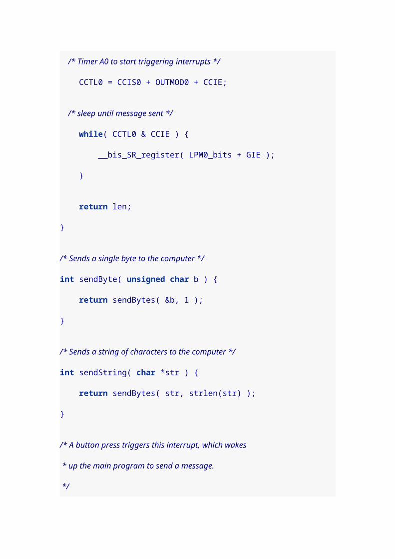
clk_high(); }
clk_low();
d <<= 1; // Shift next bit into position. }
data_read(); // Set data line to receive. clk_high(); // Clock goes high to wait for acknowledge.
// Slave will pull data line low to acknowledge. int i = 20; while( P1IN & I2C_SDA ) { // Else toggle the clock line and check again clk_low(); clk_high();
// Timeout eventually, leaving Stop condition. if( ! --i ) { I2C_Stop(); return; } }
clk_low();}
/* Initializes the LCD panel. */void init_LCD(void) { I2C_Start();
I2C_out( 0x78 ); // Slave address of the LCD panel. I2C_out( 0x00 ); // Control byte: all following bytes are commands. I2C_out( 0x38 ); // 8-bit bus, 2-line display, normal instruction mode. delay( 10 );
I2C_out( 0x39 ); // 8-bit bus, 2-line display, extension instruction mode. delay( 10 );
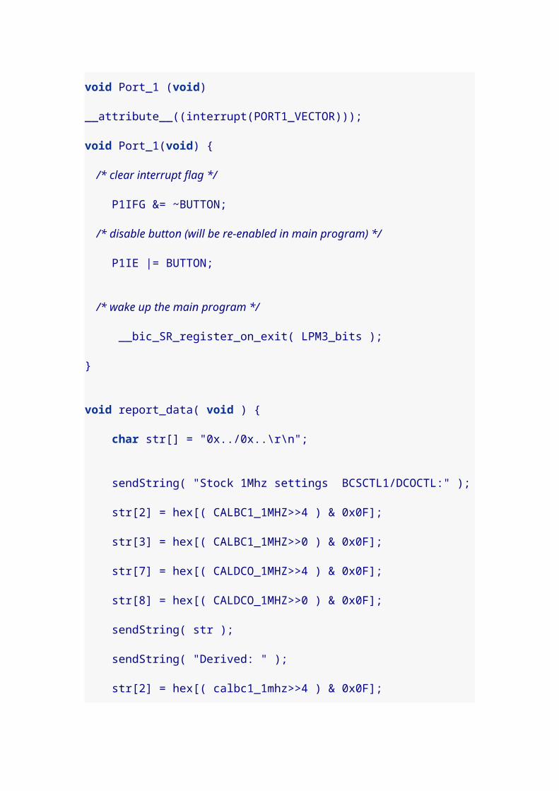
I2C_out( 0x14 ); // Bias set to 1/5. I2C_out( 0x78 ); // Contrast set. I2C_out( 0x5E ); // Icon display on, booster on, contrast set. I2C_out( 0x6D ); // Follower circuit on, amplifier=1? I2C_out( 0x0C ); // Display on, cursor off. I2C_out( 0x01 ); // Clear display. I2C_out( 0x06 ); // Entry mode set to cursor-moves-right. delay( 10 );
I2C_Stop();}
/* Sends the "clear display" command to the LCD. */void clear_display(void) { I2C_Start();
I2C_out( 0x78 ); // Slave address of panel. I2C_out( 0x00 ); // Control byte: all following bytes are commands. I2C_out( 0x01 ); // Clear display.
I2C_Stop();}
/* Writes a 40-char string to the RAM of the LCD. */void show40( unsigned char *text ) { int n;
I2C_Start();
I2C_out( 0x78 ); // Slave address of panel. I2C_out( 0x40 ); // Control byte: data bytes follow, data is RAM data.
for( n = 0; n < 40; n++ ) { I2C_out( *text++ ); }
I2C_Stop();}

int main(void) { int i;
/* Stop the watchdog timer so it doesn't reset our chip */ WDTCTL = WDTPW + WDTHOLD;
/* Only output lines are the lights, which start green on, red off */ P1DIR |= BIT0 + BIT6;
/* Data and clock lines are read pins that go low when set for output */ P1DIR &= ~(I2C_SDA + I2C_SCL); P1OUT &= ~( I2C_SDA + I2C_SCL );
/* We use an interrupt handler to detect start/stop conditions, * and some arbitration errors. */ if( P1IN & I2C_SDA ) { P1OUT |= BIT6; // green on to show bus clear P1IES |= I2C_SDA; // trigger on falling edge } else { P1OUT &= ~BIT6; // off to show someone on the bus P1IES &= ~I2C_SDA; // trigger on rising edge } P1IE |= I2C_SDA; // enable interrupt P1IFG &= ~I2C_SDA; // clear interrupt flag __bis_SR_register( GIE ); // general interrupt enable
delay(400);
init_LCD(); delay(99);
#if 1 srand(100); while( 1 ) {

show40( "1 1 1 1 1 1-1-1-1-1-----------" ); delay( rand()%9 ); show40( "1+1+1+1+1+++++++++++1*1*1*1*1***********" ); delay( rand()%9 ); show40( "1/1/1/1/1///////////1=1=1=1=1===========" ); delay( rand()%9 ); }#else srand(200); while( 1 ) { show40( " 2 2 2 2 2 -2-2-2-2-2----------" ); delay( rand()%9 ); show40( "+2+2+2+2+2++++++++++*2*2*2*2*2**********" ); delay( rand()%9 ); show40( "/2/2/2/2/2//////////=2=2=2=2=2==========" ); delay( rand()%9 ); }#endif}
There’s a fair bit of new stuff in this program. One small
addition right at the beginning is in clk_high(). After the
clock line is raised, a loop checks to ensure that another
device is not still holding the clock line low, and waits for
the other device to let go. This allows slower devices to
invoke "clock stretching," effectively slowing down the
interface. The loop eventually times out, but the duration
can be tuned if necessary by changing the number of
iterations of the loop.

The Port1 interrupt handler is used to detect when another
master has control of the bus. It is somewhat modified from
the monitor program. The main change is a logical
reorganization, based on the premise that we can divide
events into two types, either the Stop condition has been
triggered, or another master has the bus. There is no need
to distinguish a Start from any other kind of active use of
the bus.
The lost_arbitration() function exists for situations where
we thought we were the sole master on the serial bus and
then discovered that another master is also using the bus.
In every case, this is discovered when the data line has
been pulled low while we expected it to be high. This
function resets the global flags and interrupts, so we can
wait for the bus to become free.
The I2C_Start() and I2C_Stop() functions are only slightly
changed. Each makes appropriate changes to the interrupt
handling behavior and global variables, reflecting that we
are taking control of or releasing the bus. The start function
checks for arbitration losses.

Similarly, the I2C_out() function checks after every 1 (high)
bit to make sure another master is not pulling the data line
low. We relinquish the bus if there is such a conflict. The
ACK check is also slightly modified to specifically invoke the
Stop condition in the case of a timeout of the loop.
None of the other changes are related to I2C.
The show40() routine was modified to write an entire line of
the LCD (even the invisible right half of the display). And
the main() method was divided into separate ifdef divided
sections to make it easier to rebuild the program for two
different Launchpads connected together. Buy putting
different strings on each chip, we can tell which one is
successfully communicating with the LCD. Change the 1 to
a 0 to build the alternative program.
Build and install with:
msp430-gcc -O2 -mmcu=msp430x2211 -o lcddemo2.elf lcddemo2.c && mspdebug rf2500 "prog lcddemo2.elf"
Each board will light the green LED when it believes the
bus is free to use (or when it is actually acting as the
master). When the program detects that another device is
on the bus, the green LED goes out.

If a program is communicating with the bus and loses
arbitration, then the green light will toggle off and the red
light will come on. This will last until a stop condition is
detected. At that point, the red light goes off and the green
comes back on.
This code is pretty reliable, but I found it was rare yet
possible for both programs to relinquish the bus with an
arbitration error (presumably the LCD panel did
something), and then a dead-lock condition occurs with
everyone waiting on everyone else. For most reliable
operation, there is probably just enough room on the 2K
ROM to add a timeout handler and reset things. If no
activity has been detected in several seconds after an error,
then it’s probably safe to resume. (We may need to trigger
the reset pin of the LCD and send another initialization
sequence.)
Here’s a picture of 3 Launchpads running this code. There
are a few extra wires not strictly required to make it go. For
convenience, I connected all of the S1 switches together
and all of the S2 switches together (so I could reset the
boards simultaneous or reset the LCD by pushing the

switches on any board). Notice that the green light is lit on
the second board (because it was controlling the bus), and
if you look at the LCD, you can see that the second row was
caught by the camera just as it was changing to 2s.

6. Messages in memory

I have an idea to make a little sign that scrolls between
different messages. So far, my I2C code uses almost all of
the 2K Flash memory of my MSP430 chips, which doesn’t
leave much room for messages. You can check the size of an
MSP430 binary with the msp430-size utility, like this:
c$ msp430-size lcddemo2.elf text data bss dec hex filename 1964 4 4 1972 7b4 lcddemo2.elf
6.1. Adding a memory chip
To hold my messages, I intend to use a Microchip brand
24LC512-I/P Flash chip. It can hold 512 kilobits of data (or
512÷8=64 kilobytes) in pages of 128 bytes. You read and
write data from the chip using the I2C protocol, so I can re-
use the I2c code that I already have.
I ordered mine from Newark, part # 62K0581. Sparkfun
also has a 256kb version at the time of this writing.
Compared to the LCD panel, I found the memory chip very
simple to wire up. There are 8 pins. Pin 4 is Vss and is
connected to ground. Diagonally opposite, pin 8 is Vcc and
connected to power.
Pins 1, 2, and 3 are used to specify 3 bits of the memory
chip’s I2C address (so you can configure up to 8 different

memory chips on the same bus). The data sheet simply
stated that each should be "tied" to Vcc or Vss to set a
single 1 or 0. It did not say whether a resistor was required,
but it didn’t seem to hurt. I connected all three pins,
together with the write protect pin (pin 7) through a 10K
ohm resister to ground.
Finally, pin 5 is SDA, which I connected to the SDA of the
microcontroller and the LCD. And pin 6 is SCL, which I
connected to the SCL of the microcontroller and the LCD.
The master on the I2C bus will be the MSP430, and it will
have two slaves.
6.2. LCD changes
I went back to the data sheet to learn how to control the
contrast of the LCD panel. It was pretty straightforward to
control during the initialization step, and I have now
removed the 3900 ohm resistor connecting the LCD Vout
and Vdd/Vcc pins.
I’ve also added some helper functions to write messages in
specified locations of the LCD RAM. That way I can choose
to write a new message on the second line or randomly at
any position on screen.

6.3. I2C changes
To make space for new code, I decided that for this
program I won’t worry about multi-master scenarios. I
removed the interrupt handler and code that watched for
other masters on the bus. I did leave the clock stretching
code.
One new addition to the I2C code is the
function I2C_in() which reads data from a slave. I didn’t
need that for the LCD panel, but now that we want to read
from a flash chip, that will be important. It take a single
argument, a flag whether to acknowledge the byte or not
(the convention is to acknowledge every byte except the last
one). Perhaps, this should be rewritten to read an array of
bytes, but this works for now.
#include <msp430g2211.h>
#define I2C_SDA BIT7 // Data line#define I2C_SCL BIT6 // Clock line
// Legal contrast values from 0 to 63#define CONTRAST 30#define CLOW (CONTRAST & 0x0F)#define CHIGH ((CONTRAST>>4) & 0x03)
int error_occurred = 0;int we_are_master = 0;
/* A crude delay function. Tune by changing the constant. */

inline void delay( unsigned int n ) { volatile unsigned int i = n<<2; while( i-- ) ;}
inline void data_read(void ) { P1DIR &= ~I2C_SDA; // float to get ready to read}
inline void data_high(void ) { P1DIR &= ~I2C_SDA; // float pin to go high delay( 5 );}
inline void data_low(void ) { P1DIR |= I2C_SDA; delay( 5 );}
void clk_high(void) { P1DIR &= ~I2C_SCL; // float pin to go high
int i = 100; while( !(P1IN & I2C_SCL) && i-- ) ; // clock stretching
delay( 10 );}
inline void clk_low(void) { P1DIR |= I2C_SCL; delay( 5 );}
inline int data_pulled_down(void) { return ! (P1IN & I2C_SDA );}
inline int data_pulled_up(void) { return (P1IN & I2C_SDA );}
/* As sole master, we should never lose arbitration. * This is more of an error check. */
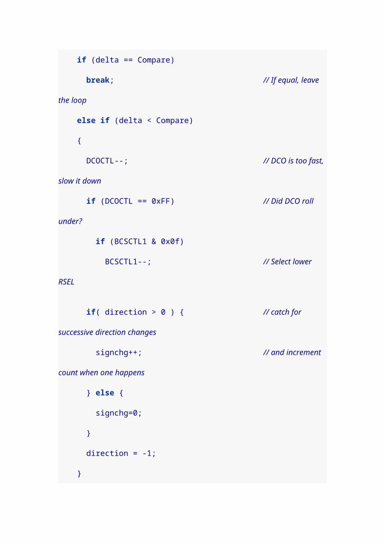
inline void lost_arbitration() { we_are_master = 0; error_occurred = 1;
P1OUT ^= BIT0; // toggle red}
/* I2C communication starts when both the data and clock * lines go low, in that order. */void I2C_Start(void) { clk_high(); data_high();
if( data_pulled_down()) { // someone else has the bus lost_arbitration(); return; }
data_low(); clk_low();
we_are_master = 1;}
/* I2C communication stops with both the clock and data * lines going high, in that order. */void I2C_Stop(void) { if( ! we_are_master ) return;
data_low(); clk_low();
clk_high(); data_high();
we_are_master = 0;}
/* Outputs 8-bit command or data via I2C lines. */void I2C_out(unsigned char d) { int n;
if( ! we_are_master ) return;

for( n = 0; n < 8; n++ ) { if( d & 0x80 ) { data_high(); clk_high();
/* If the line is 0, some other master is * controlling the line, and we should drop out. */ if( data_pulled_down()) { lost_arbitration(); return; } } else { data_low(); clk_high(); }
clk_low();
d <<= 1; // Shift next bit into position. }
data_read(); // Set data line to receive. clk_high(); // Clock goes high to wait for acknowledge.
// Slave will pull data line low to acknowledge. int i = 20; while( P1IN & I2C_SDA ) { // Else toggle the clock line and check again clk_low(); clk_high();
// Timeout eventually, leaving Stop condition. if( ! --i ) { I2C_Stop(); return; } }
clk_low();}
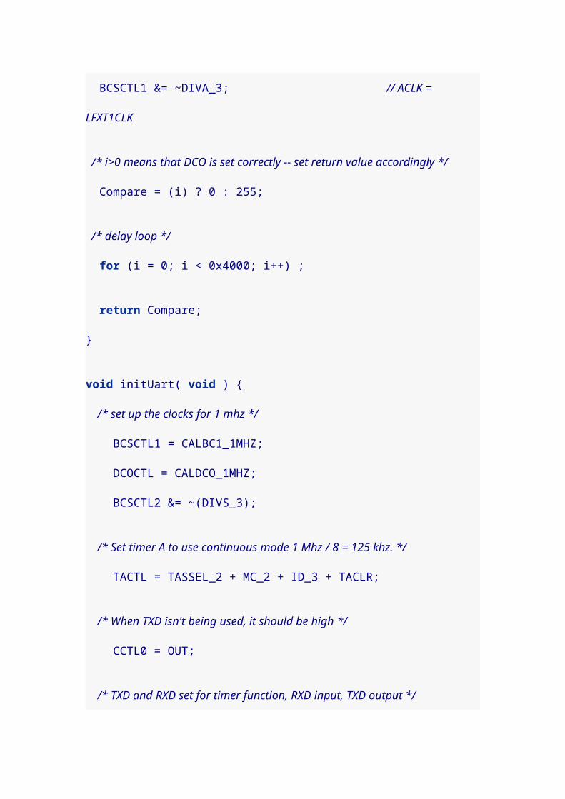
/* Inputs 8-bit data from slave, with or without acknowledgement. */unsigned char I2C_in(int ack) { int n; unsigned char byte = 0;
if( ! we_are_master ) return 0;
data_read(); // Float line to read bits. for( n = 0; n < 8; n++ ) { byte <<= 1; // Shift bits over to make room for new bit.
clk_high();
if( data_pulled_up()) { byte |= 1; // Slave sent a 1. }
clk_low(); }
/* If we need to acknowledge, we'll pull down the data line. */ if( ack ) { data_low(); }
clk_high(); clk_low();
return byte;}
/* Initializes the LCD panel. */void init_LCD(void) { I2C_Start();
I2C_out( 0x78 ); // Slave address of the LCD panel. I2C_out( 0x00 ); // Control byte: all following bytes are commands.

I2C_out( 0x38 ); // 8-bit bus, 2-line display, normal instruction mode. delay( 10 );
I2C_out( 0x39 ); // 8-bit bus, 2-line display, extension instruction mode. delay( 10 );
I2C_out( 0x14 ); // Bias set to 1/5. I2C_out( 0x70 | CLOW ); // Contrast set. I2C_out( 0x5C | CHIGH); // Icon display on, booster on, contrast set. I2C_out( 0x6D ); // Follower circuit on, amplifier=1? I2C_out( 0x0C ); // Display on, cursor off. I2C_out( 0x01 ); // Clear display. I2C_out( 0x06 ); // Entry mode set to cursor-moves-right. delay( 10 );
I2C_Stop();}
/* Sends the "clear display" command to the LCD. */void clear_display(void) { I2C_Start();
I2C_out( 0x78 ); // Slave address of panel. I2C_out( 0x00 ); // Control byte: all following bytes are commands. I2C_out( 0x01 ); // Clear display.
I2C_Stop();}
/* Shows a string of bytes on the LCD at the current position */void show( unsigned char *bytes, int n ) { I2C_Start();
I2C_out( 0x78 ); // Slave address of panel. I2C_out( 0x40 ); // Control byte: data bytes follow, data is RAM data.

while ( n-- ) { I2C_out( *bytes++ ); // Put character. }
I2C_Stop();}
/* Shows a string of bytes on the LCD beginning from * the specified address/position. */void showAt( int addr, unsigned char *bytes, int n ) { I2C_Start();
I2C_out( 0x78 ); // Slave address of panel. I2C_out( 0x80 ); // Next byte is command, followed by control byte. I2C_out( 0x80 | addr ); // move to address addr I2C_out( 0x40 ); // Control byte: data bytes follow, data is RAM data.
while ( n-- ) { I2C_out( *bytes++ ); // Put character. }
I2C_Stop();}
/* Reads a sequential string of n bytes from Flash at the * current addr. Assumes n>=1. */void readNextByteSeq( unsigned char *c, int n ) { I2C_Start(); I2C_out( 0xa1 ); // Slave address for reading
while( n>1 ) { *c++ = I2C_in( 1 ); // Read byte with ACK. n--; }
*c = I2C_in( 0 ); // Don't ACK the last byte.
I2C_Stop();}

/* Reads the next byte of Flash from the current addr. */unsigned char readNextByte( void ) { unsigned char byte;
readNextByteSeq( &byte, 1 ); // Read a single byte.
return byte;}
/* Read byte from Flash starting at the specified address. Sends * a Start condition, but the (Restart and) Stop is done * by the readNextByteSeq() function. */void readByteSeqAt( unsigned int addr, unsigned char *c, int n ) { I2C_Start(); I2C_out( 0xa0 ); // Slave address for writing/addressing
I2C_out( addr >> 8 ); // Address high byte I2C_out( addr & 0xff ); // Address low byte
/* Data line is high from last write, so we are ready * for another Start sequence. */
readNextByteSeq( c, n ); // Read a sequence of bytes.}
/* Read a byte from Flash at the specified address. Sends * a Start condition, but the (Restart and) Stop is done * by the readNextByteSeq() function. */unsigned char readByteAt( unsigned int addr ) { unsigned char byte;
readByteSeqAt( addr, &byte, 1 ); // Read a single byte.
return byte;}

/* Write bytes to Flash starting at the specified address. */void writeByteSeqAt( unsigned int addr, unsigned char *c, int n ) { I2C_Start(); I2C_out( 0xa0 ); // Slave address for writing/addressing
I2C_out( addr >> 8 ); // Address high byte I2C_out( addr & 0xff ); // Address low byte
while( n>0 ) { I2C_out( *c++ ); n--; }
I2C_Stop();
/* Wait for write sequence to complete. Attempt to start a * new communication and check for an ACK. */ do { I2C_Start(); I2C_out( 0xa0 ); } while( ! we_are_master );
/* finally got an ACK, so we can continue */ I2C_Stop();}
/* Write a single byte at the specified address */void writeByteAt( unsigned int addr, unsigned char byte ) { writeByteSeqAt( addr, &byte, 1 );}
int main(void) { int i; unsigned char buffer[10] = "whitestar"; unsigned char buffer1[10] = "blackstar";
/* Stop the watchdog timer so it doesn't reset our chip */ WDTCTL = WDTPW + WDTHOLD;
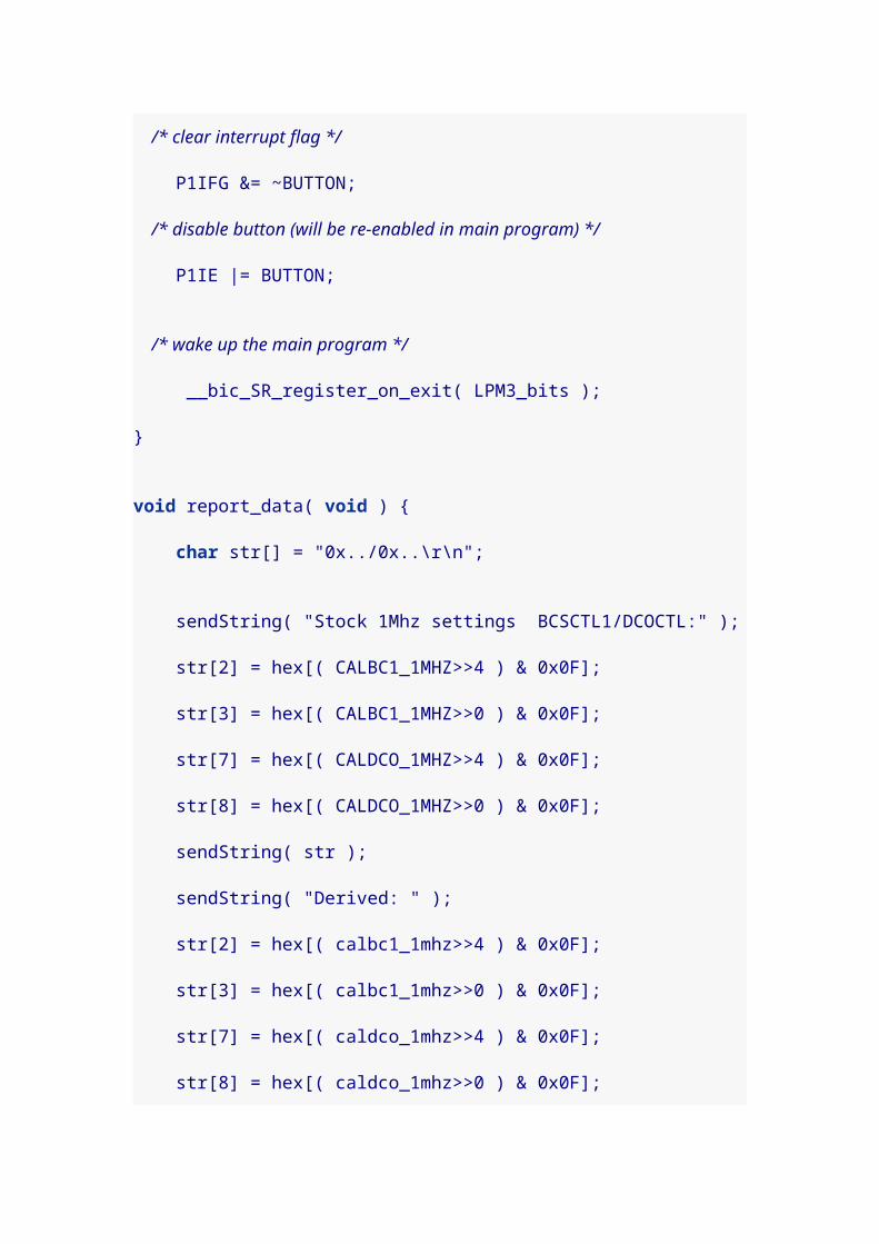
/* Only output line is red, which starts off */ P1DIR |= BIT0; P1OUT &= ~BIT0;
/* Data and clock lines are read pins that go low when set for output */ P1DIR &= ~(I2C_SDA + I2C_SCL); P1OUT &= ~( I2C_SDA + I2C_SCL );
delay(400);
init_LCD(); delay(99);
// Read starting bytes of memory //writeByteSeqAt( 0, buffer, sizeof(buffer)); //writeByteSeqAt( 0, buffer1, sizeof(buffer1)); readByteSeqAt( 0, buffer, sizeof(buffer));
// Show message on second line of the LCD showAt( 0x40, buffer, sizeof(buffer));}
I found it a little unclear that the second line of the screen starts at memory location 0x40 in the display. Apparently, if you load data sequentially into the display, it loads locations 0-39 (decimal), then skips to 64-103 (decimal). I initially thought the 0x40 in the data sheet was simply a mistake, since it was the 40th character loaded, but apparently not.
Uncomment the writeByteSeqAt() calls in the main method
to record new data into the Flash chip.
7. Capacitive Touch
Newer MSP430 chips have touch-enabled pins on them. But
I discovered while searching for information, that any
MSP430 can be programmed to do capacitive touch. This
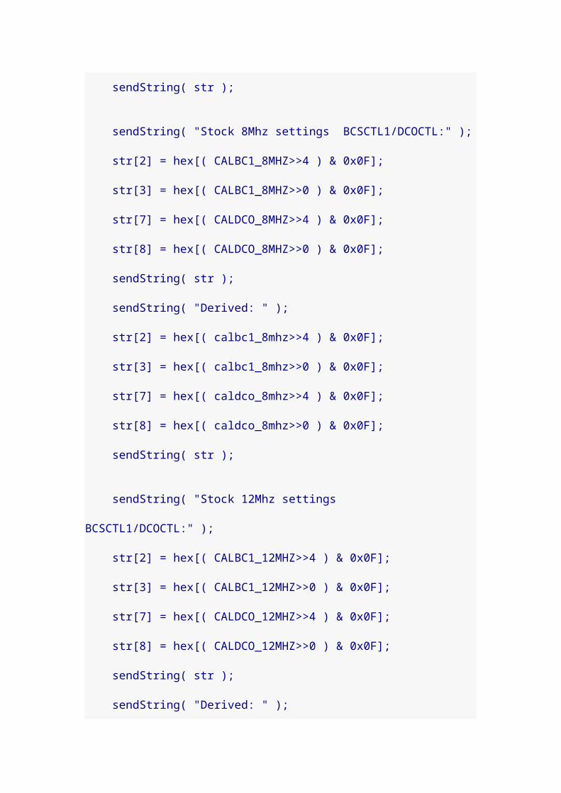
document was very helpful in working out the
technique: MSP430 touch pad experiments.pdf. I also found
the discussion of sampling from this page helpful: Sample
Rate Jittering.
The idea for measuring a capacitive touch plate is pretty
straightforward. You just apply a voltage to it and see how
long it takes to charge. Apply ground and see how long it
takes to discharge. If the time increases, the capacitance
has gone up (and that’s what happens when you touch the
plate).
If you wire things correctly, a pair of pins on the MSP430
can monitor a pair of touch plates (which don’t have to be
anything special, basically anything metal you can touch).
For my experiment, I chose pins 4 and 5. The configuration
is simple. Connect the pins with a large value resistor;
typical values I found in reading were 5M ohms and 5.1M
ohms. Then connect a lead from pin 4 to one plate, and from
pin 5 to another plate.
For my plates, I initially just used two jumper wires, and I
touched the bare unconnected ends. But I think I may
eventually want to use the technique to make a Morse code

keyer, and I’ll actually want plates to touch. So I stopped at
Radio Shack and bought some 2-sided copper clad (not
knowing if it would be better if the back side were
grounded). I scored it and snapped off two small strips.
Here’s a picture of my experiment. I labeled the resistor,
which is actually five 1M ohm resistors in series, since
that’s the largest value I had on hand. The I2C memory chip
is still on my breadboard, but that isn’t relevant to this
experiment. You can clearly see plastic wrap covering my
plates (to verify that you don’t actually have to touch the
plate electrically to get it to work).

Most of the code is copied from my previous I2C projects.
The most interesting new parts are:
A Port 1 interrupt handler
The measure_key_capacitance() function, which is the
most important new part.

The sample_key() function, which helps eliminate the
effect of noise.
Check out the code. Then we can discuss.
#include <msp430g2211.h>
#define I2C_SDA BIT7 // Data line#define I2C_SCL BIT6 // Clock line
// Legal contrast values from 0 to 63#define CONTRAST 30#define CLOW (CONTRAST & 0x0F)#define CHIGH ((CONTRAST>>4) & 0x03)
/* This has to be volatile, so the compiler knows it may change. * Otherwise, optimizations will make you sorry! */volatile unsigned int timer_count;
int error_occurred = 0;int we_are_master = 0;
/* A crude delay function. Tune by changing the constant. */inline void delay( unsigned int n ) { volatile unsigned int i = n<<2; while( i-- ) ;}
inline void data_read(void ) { P1DIR &= ~I2C_SDA; // float to get ready to read}
inline void data_high(void ) { P1DIR &= ~I2C_SDA; // float pin to go high delay( 5 );}
inline void data_low(void ) { P1DIR |= I2C_SDA; delay( 5 );

}
void clk_high(void) { P1DIR &= ~I2C_SCL; // float pin to go high
int i = 100; while( !(P1IN & I2C_SCL) && i-- ) ; // clock stretching
delay( 10 );}
inline void clk_low(void) { P1DIR |= I2C_SCL; delay( 5 );}
inline int data_pulled_down(void) { return ! (P1IN & I2C_SDA );}
inline int data_pulled_up(void) { return (P1IN & I2C_SDA );}
/* As sole master, we should never lose arbitration. * This is more of an error check. */inline void lost_arbitration() { we_are_master = 0; error_occurred = 1;
P1OUT ^= BIT0; // toggle red}
/* I2C communication starts when both the data and clock * lines go low, in that order. */void I2C_Start(void) { clk_high(); data_high();
if( data_pulled_down()) { // someone else has the bus lost_arbitration(); return;

}
data_low(); clk_low();
we_are_master = 1;}
/* I2C communication stops with both the clock and data * lines going high, in that order. */void I2C_Stop(void) { if( ! we_are_master ) return;
data_low(); clk_low();
clk_high(); data_high();
we_are_master = 0;}
/* Outputs 8-bit command or data via I2C lines. */void I2C_out(unsigned char d) { int n;
if( ! we_are_master ) return;
for( n = 0; n < 8; n++ ) { if( d & 0x80 ) { data_high(); clk_high();
/* If the line is 0, some other master is * controlling the line, and we should drop out. */ if( data_pulled_down()) { lost_arbitration(); return; } } else { data_low(); clk_high(); }

clk_low();
d <<= 1; // Shift next bit into position. }
data_read(); // Set data line to receive. clk_high(); // Clock goes high to wait for acknowledge.
// Slave will pull data line low to acknowledge. int i = 20; while( P1IN & I2C_SDA ) { // Else toggle the clock line and check again clk_low(); clk_high();
// Timeout eventually, leaving Stop condition. if( ! --i ) { I2C_Stop(); return; } }
clk_low();}
/* Initializes the LCD panel. */void init_LCD(void) { I2C_Start();
I2C_out( 0x78 ); // Slave address of the LCD panel. I2C_out( 0x00 ); // Control byte: all following bytes are commands. I2C_out( 0x38 ); // 8-bit bus, 2-line display, normal instruction mode. delay( 10 );
I2C_out( 0x39 ); // 8-bit bus, 2-line display, extension instruction mode. delay( 10 );
I2C_out( 0x14 ); // Bias set to 1/5.
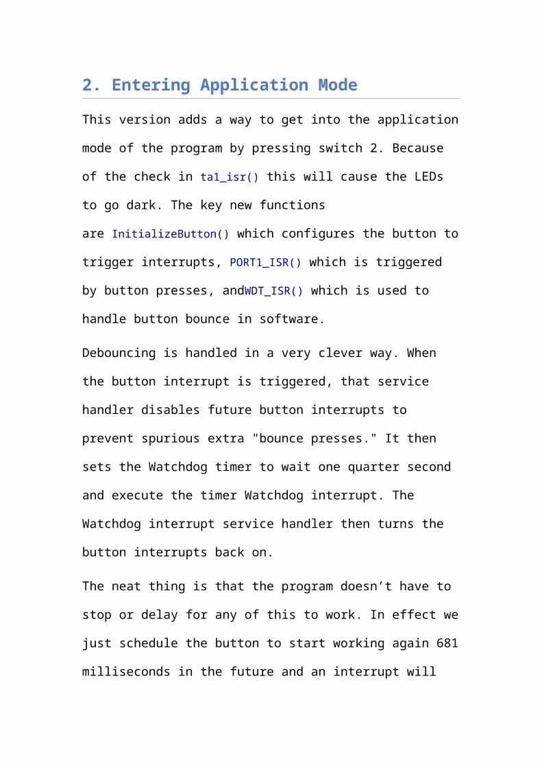
I2C_out( 0x70 | CLOW ); // Contrast set. I2C_out( 0x5C | CHIGH); // Icon display on, booster on, contrast set. I2C_out( 0x6D ); // Follower circuit on, amplifier=1? I2C_out( 0x0C ); // Display on, cursor off. I2C_out( 0x01 ); // Clear display. I2C_out( 0x06 ); // Entry mode set to cursor-moves-right. delay( 10 );
I2C_Stop();}
/* Sends the "clear display" command to the LCD. */void clear_display(void) { I2C_Start();
I2C_out( 0x78 ); // Slave address of panel. I2C_out( 0x00 ); // Control byte: all following bytes are commands. I2C_out( 0x01 ); // Clear display.
I2C_Stop();}
/* Shows a string of bytes on the LCD at the current position */void show( unsigned char *bytes, int n ) { I2C_Start();
I2C_out( 0x78 ); // Slave address of panel. I2C_out( 0x40 ); // Control byte: data bytes follow, data is RAM data.
while ( n-- ) { I2C_out( *bytes++ ); // Put character. }
I2C_Stop();}
/* Shows a string of bytes on the LCD beginning from * the specified address/position. */

void showAt( int addr, unsigned char *bytes, int n ) { I2C_Start();
I2C_out( 0x78 ); // Slave address of panel. I2C_out( 0x80 ); // Next byte is command, followed by control byte. I2C_out( 0x80 | addr ); // move to address addr I2C_out( 0x40 ); // Control byte: data bytes follow, data is RAM data.
while ( n-- ) { I2C_out( *bytes++ ); // Put character. }
I2C_Stop();}
/* This triggers when a pad has been charged or discharged. When it returns, * timer_count will hold the elapsed count of charging or discharging time for * the key. Setup for triggering this interrupt happens in * measure_key_capacitance(). */void Port_1 (void) __attribute__((interrupt(PORT1_VECTOR)));void Port_1 (void) { P1IFG = 0; timer_count = TAR - timer_count; __bic_SR_register_on_exit( LPM0_bits );}
/* Returns a value the reflects the capacitance of one of two key pads * connected by a large value resistor. Assumes key to be BIT4 or BIT5. */unsigned int measure_key_capacitance( unsigned int key ) { static unsigned int sum;
P1OUT &= ~(BIT4 + BIT5); // Start with both keys low.

/* charge key */ P1OUT |= key; asm( "nop \n\t" "nop \n\t" "nop \n\t" );
/* Set up interrupt to trigger on key. */ P1IES |= key; // Trigger on voltage drop. P1IE |= key; // Interrupt on. P1DIR &= ~key; // Float key and let voltage drop.
timer_count = TAR; // Get timer (to compare with in interrupt). __bis_SR_register( LPM0_bits + GIE ); // Sleep.
P1IE &= ~key; // Disable interrupts on key. P1OUT &= ~key; // Discharge key by setting P1DIR |= key; // active low.
sum = timer_count; // Save the count that was recorded in interrupt.
/* Charge the complement line. */ P1OUT |= (BIT4 + BIT5)^key; asm( "nop \n\t" "nop \n\t" "nop \n\t" );
/* Set up interrupt to trigger on key. */ P1IES &= ~key; // Trigger on voltage rise. P1IE |= key; // Interrupt on. P1DIR &= ~key; // Float key and let voltage rise.
timer_count = TAR; // Get timer (to compare with in interrupt). __bis_SR_register( LPM0_bits + GIE );
P1IE &= ~key; // Disable interrupts on key. P1OUT &= ~(BIT4 + BIT5); // Set both keys to P1DIR |= (BIT4 + BIT5); // active low.
return sum + timer_count; // Return the sum of both counts.}

/* Computes a trimmed mean of 18 capacitance values, trimming the largest and * smallest samples. */unsigned int sample_key( unsigned char key ) { int i, j, small, large, cap; long int total;
total = 0;
/* Measure once to initialize max and min values. */ small = large = measure_key_capacitance( key );
/* Seventeen more samples happen here. Each time we decide whether the new * sample is kept or if it replaces one of the extremes. */ for( i = 1; i < 18; i++ ) { cap = measure_key_capacitance( key ); if( cap < small ) { total += small; small = cap; } else if( cap > large ) { total += large; large = cap; } else { total += cap; }
// Add some jitter here, for more effective sampling. for( j=0; j < (cap&0x0F); j++ ) asm( "nop \n\t" ); }
/* We average 16 values (not including the two extremes) */ return total >> 4;}
/* Converts an integer to a string of digits. Assumes * the integer is between -99999 and +99999. */char buf[7];char *int2str( int x ) { int num = x;

int idx = 6;
/* Leading minus for negative numbers. */ buf[0] = ( num < 0 ) ? '-' : ' '; if( num < 0 ) num = -num;
buf[6] = '\0';
/* Fill in the digits from the right. Convert leading zeros to spaces. */ do { idx--;
if( idx < 5 && !num ) { buf[idx] = ' '; } else { buf[idx] = num%10 + '0'; num /= 10; } } while( idx>1 );
return buf;}
int main(void) { int i, j; int flag1=0, flag2=0; int baseline1, baseline2, samp1, samp2;
/* Stop the watchdog timer so it doesn't reset our chip. */ WDTCTL = WDTPW + WDTHOLD;
/* Only output line is red, which starts off. */ P1DIR |= BIT0; P1OUT &= ~BIT0;
/* Data and clock lines are read pins that go low when set for output. */ P1DIR &= ~(I2C_SDA + I2C_SCL); P1OUT &= ~(I2C_SDA + I2C_SCL);
delay(400); // Give LCD panel time to wake up.

init_LCD(); delay(99);
/* Setup for capacitive touch. Timer A is in count up mode, driven by the * submain clock (1 Mhz) with a clock divider of 2^2=4. The pins for our * touch pads are set as output pins. */ TACTL = MC_2 + TASSEL_2 + ID_2; // count up mode, SMCLK, /4 P1DIR |= BIT4 + BIT5;
/* Get baseline values for each key. */ baseline1 = sample_key(BIT4); baseline2 = sample_key(BIT5);
/* Uncomment to see baseline values for each key. */ //showAt(0x40, int2str( baseline1 ), 6 ); //showAt(0x40+10, int2str( baseline2 ), 6 ); while( 1 ) { samp1 = sample_key(BIT4); samp2 = sample_key(BIT5);
#if 0 /* Uncomment to see running sample values for each key. */ showAt( 0, int2str( samp1 ), 6 ); showAt(10, int2str( samp2 ), 6 );#else /* If the sample exceeds the baseline by 20% (i.e. if * samp1 > 1.2*baseline1 ), then print a message. */ if( 5*samp1 > 6*baseline1 ) { if( !flag1 ) { showAt(0, "Pin 4", 5 ); flag1 = 1; } } else if( flag1 ) { showAt(0, " ", 5 ); flag1 = 0; }

/* If the sample exceeds the baseline by 20% (i.e. if * samp2 > 1.2*baseline2 ), then print a message. */ if( 5*samp2 > 6*baseline2 ) { if( !flag2 ) { showAt(0x40, "Pin 5", 5 ); flag2 = 1; } } else if( flag2 ) { showAt(0x40, " ", 5 ); flag2 = 0; }#endif }}
The key to the program is
the measure_key_capacitance() function. It actually takes two
measures of the capacitance of the key; and you get to
specify the key, either BIT4 or BIT5. First it charges the
key, then measures the time for it to discharge through the
5M ohm resistor (by recording the value of a timer and
setting an interrupt to trigger on Port 1 when the voltage
has fallen). Then it takes a second reading by discharging
the pin, and then charging the plate from the other pin
through the same resister (again measuring the time with
the Port 1 interrupt handler). The sum of the charge and
discharge times becomes our measure of capacitance.

The capacitance values can fluctuate quite a bit, and I read
about a couple of different compensating techniques.
Effectively, everyone recommends some kind of low pass
filter (i.e. code that will minimize the effects of high-
frequency oscillations). I tried many different things, but I
eventually settled on a trimmed mean. It’s very easy to
understand, and it gave me consistent performance.
[Another technique I might also consider is trimming two
values from the big end, since the probability distribution is
right skewed; then average the rest.]
The sample_key() function simply measures the capacitance
of the same key 18 times in succession. It throws out the
lowest and highest values and averages the other 16. One
other line worth noting in that function is the inner loop
of nop instructions. The idea of that is to randomize slightly
when the samples are drawn, following ideas of: Sample
Rate Jittering.
The main() method is essentially just a bit of initialization
code and a loop to repeatedly sample the keys. I took a bit
of care about updating the LCD only when a status has
changed (that’s the point of flag1 and flag2) since writing

the LCD is much slower that testing the keys. Continuously
writing unnecessary updates to the LCD just slows down
the program. I could imagine sleeping in this loop and using
a timer interrupt to wake periodically for key sampling.
That would very likely consume much less power.
I also left code lines (commented out) for displaying the raw
capacitance values. You might need these to tune your own
setup or just to see if things are working at all.
If you liked this project, you might check out my attempts to
create a Morse code touch keyer. I was not as successful as
I hoped to be, but I think the attempt is still pretty
interesting.
Last updated 2011-11-23 11:24:23 CST
24. Bit-bang SPI interface for ktm-s1201 LCD panel
Another LCD panel; this one does SPI communication (and
that means I needed to learn about I2C).
Also broken out into its own page: lcd_spi.html

SPI experiments with the MSP430Don Bindner<[email protected]>Table of Contents
1. SPI communications with ktm-s1201 LCD panel
2. SPI communications with EA DOGS102 LCD panel
3. USI/SPI communications with EA DOGS102 LCD panel
This page is a companion page for my MSP430
Launchpad page.
1. SPI communications with ktm-s1201 LCD panel
I picked up a set of inexpensive 12 digit LCD panels ("new
old stock" panels) on the web. Communication is via SPI
(Serial Peripheral Interface), so I wired one up to an
msp430g2211 and started studying data sheets. Since this
microcontroller doesn’t have hardware serial support (and
since I wanted to learn about how the protocol works) I
decided to do a bit-banged serial program. To get things
wired up, I used this (somewhat abreviated) data
sheet: data/ktm-s1201.pdf
From the LCD panel, these connections are made:

Pin 1 Vcc — Vcc on the Launchpad (+3.3V)
Pin 2 Vss — GND on the Launchpad
Pin 3 SCK — P1.6 on the Launchpad (which I’ve used
for the serial clock line)
Pin 4 SI — P1.0 on the Launchpad (which I’ve used for
Master-out Slave-in line)
Pin 5 C/D — P1.7 on the Launchpad (which I’ve used
for the Command/Data selector)
Pin 6 Reset — Needs to be pulled high. This can be
done with a high-value resistor, like 10K, connected to
Vcc.
Pin 7 Busy — Can be left disconnected as long, as you
don’t drive the LCD too fast. Normally the panel uses
this line to tell the microcontroller to wait.
Pin 8 CS — P1.5 on the Launchpad (which I’ve used for
chip select)
Pin 9 Vlc — Described below
Pin 10 NC — Not connected
On the data sheet, Pin 9 is shown connected to the center
pin of a variable resistor whose ends are connected to Vcc

and GND. I used a 10K potentiometer that I had on hand.
This arrangement effectively creates a voltage divider, with
an adjustable intermediate voltage on the middle pin
(connected to Pin 9). This is how you set the contrast of the
LCD so you can actually see text on it.
There’s nothing particularly important about the specific
Launchpad pin assignments. When learning, I usually

configure significant lines on the pins that have LEDs, so I
can watch the lights and have an idea if things are working.
That’s why I put the clock line on P1.6 (so the clock line
shows on the green Launchpad LED) and the data line on
P1.0 (so data shows on the red Launchpad LED). But they
could all be changed with minimal changes to the code.
A somewhat minimal SPI bit-banging example program
follows. The key function is spi_IO(), which handles the serial
communication with the panel, effectively putting bits on
the MOSI line one at a time and pulsing the clock pin. The
other helper functions; init_lcd(), print_lcd(), and decimal_on();
all call this function.
#include <msp430g2211.h>
#define CS BIT5 // Chip Select line#define CD BIT7 // Command/Data mode line#define MOSI BIT0 // Master-out Slave-in#define SCK BIT6 // Serial clock
#if 20110706 > __MSPGCC__/* A crude delay function. */void __delay_cycles( unsigned long n ) { volatile unsigned int i = n/6; while( i-- ) ;}#endif
/* Write data to slave device. Since the LCD panel is * write-only, we don't worry about reading any bits. * Destroys the data array (normally received data would * go in its place). */

void spi_IO( unsigned char data[], int bytes ) { int i, n;
// Set Chip Select low, so LCD panel knows we are talking to it. P1OUT &= ~CS; __delay_cycles( 500 );
for( n = 0; n < bytes; n++ ) { for( i = 0; i < 8; i++ ) { // Put bits on the line, most significant bit first. if( data[n] & 0x80 ) { P1OUT |= MOSI; } else { P1OUT &= ~MOSI; } data[n] <<= 1;
// Pulse the clock low and wait to send the bit. According to // the data sheet, data is transferred on the rising edge. P1OUT &= ~SCK; __delay_cycles( 500 );
// Send the clock back high and wait to set the next bit. Normally // we'd also read the data bits here, but the LCD is write-only. P1OUT |= SCK; __delay_cycles( 500 ); } }
// Set Chip Select back high to finish the communication. // For data, this also triggers the LCD to update/display. P1OUT |= CS;}
/* Sets the LCD to command mode, and sends a 7-byte * sequence to initialize the panel. */void init_lcd( void ) { unsigned char data[] = { 0x40, // M=0(4-share-1/3 duty; FF=0) 0x30, // Unsynchronized transfers 0x18, // Blink off 0x11, // Display on

0x15, // Segment Decoder ON 0x20, // Clear Data and pointer 0x00 // Clear blink memory };
P1OUT |= CD; // set for commands
spi_IO( data, sizeof(data));}
/* Prints a string on the LCD panel using the 7 segment decoder. * Understood characters are 0x00 (zero) to 0x09 (nine) and * 0x0A to 0x0F (the symbols -, E, C, =, and space). */void print_lcd( unsigned char data[], int n ) { unsigned char copy[12]; unsigned char tmp; int i;
if( n < 1 ) return; if( n > 12 ) n=12;
// The panel expects data arranged right to left, so we'll // reverse the array of data passed before writing it out. for( i = n; i > 0; i-- ) { copy[n-i] = data[i-1]; }
P1OUT &= ~CD; // set for data
spi_IO( copy, n );}
/* Draws a decimal point n places from the right, by turning on * the individual LCD segment (OR 0x8 mask with segment memory). */void decimal_on( int n ) { unsigned char data[] = { 0x14, // Segment Decoder off 0xE0+2*n, // Set pointer 0 (plus 2 for each digit) 0xB8, // Decimal point on (OR 0x8 with memory contents) 0x15 // Segment Decoder on };

if( n < 0 || n > 11 ) return;
P1OUT |= CD; // set for commands
spi_IO( data, sizeof(data));}
void main( void ) { // Stop the watchdog timer so it doesn't reset our chip WDTCTL = WDTPW + WDTHOLD;
// These are the pins we need to drive. P1DIR |= SCK + MOSI + CS + CD;
// De-select the LCD panel and set the clock high P1OUT |= CS + SCK;
// Pause so everything has time to start up properly. __delay_cycles( 15000 );
// Initialize the LCD panel. init_lcd();
// Print a message: 1234.5 print_lcd("\1\2\3\4\5", 5 ); decimal_on( 1 );
for( ;; ) { __bis_SR_register( LPM3_bits + GIE ); }}
The next program adds functions to take advantage of most
all the features/commands offered by the LCD controller
chip on the panel (an NEC uPD7225). Details are in the data
sheet: data/upd7225.pdf This data sheet is also where I
learned specifics of the serial protocol (that bits are written
on the rising clock edge for example).
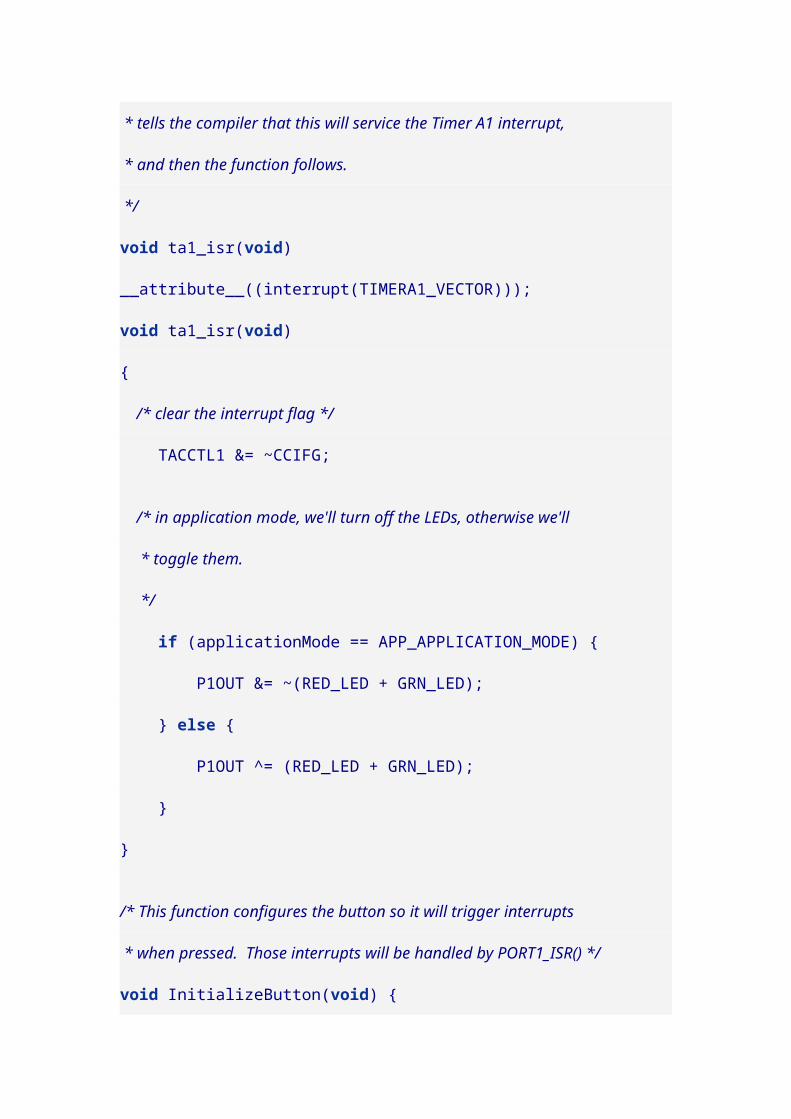
The decimal_off() function complements
the decimal_on() function.
The write_segments() function can turn on arbitrary segments
of the display, so symbols other than the stock 15 symbols
may be displayed. For example capital A and lower case b
could be displayed by turning on the correct individual
segments.
The write_blinking() function is similar, but it marks segments
on the display that (if also set in the segment memory) will
blink on and off. The blink_on() and blink_off() modify the
master flag that controls whether blinking happens. Finally,
the display_on() and display_off() turn on and off the entire
display.
#include <msp430g2211.h>
#define CS BIT5 // Chip Select line#define CD BIT7 // Command/Data mode line#define MOSI BIT0 // Master-out Slave-in#define SCK BIT6 // Serial clock
#if 20110706 > __MSPGCC__/* A crude delay function. */void __delay_cycles( unsigned long n ) { volatile unsigned int i = n/6; while( i-- ) ;}#endif
/* Write data to slave device. Since the LCD panel is

* write-only, we don't worry about reading any bits. * Destroys the data array (normally received data would * go in its place). */void spi_IO( unsigned char data[], int bytes ) { int i, n;
// Set Chip Select low, so LCD panel knows we are talking to it. P1OUT &= ~CS; __delay_cycles( 500 );
for( n = 0; n < bytes; n++ ) { for( i = 0; i < 8; i++ ) { // Put bits on the line, most significant bit first. if( data[n] & 0x80 ) { P1OUT |= MOSI; } else { P1OUT &= ~MOSI; } data[n] <<= 1;
// Pulse the clock low and wait to send the bit. According to // the data sheet, data is transferred on the rising edge. P1OUT &= ~SCK; __delay_cycles( 500 );
// Send the clock back high and wait to set the next bit. Normally // we'd also read the data bits here, but the LCD is write-only. P1OUT |= SCK; __delay_cycles( 500 ); } }
// Set Chip Select back high to finish the communication. // For data, this also triggers the LCD to update/display. P1OUT |= CS;}
/* Sets the LCD to command mode, and sends a 7-byte * sequence to initialize the panel. */void init_lcd( void ) { unsigned char data[] = { 0x40, // M=0(4-share-1/3 duty; FF=0)
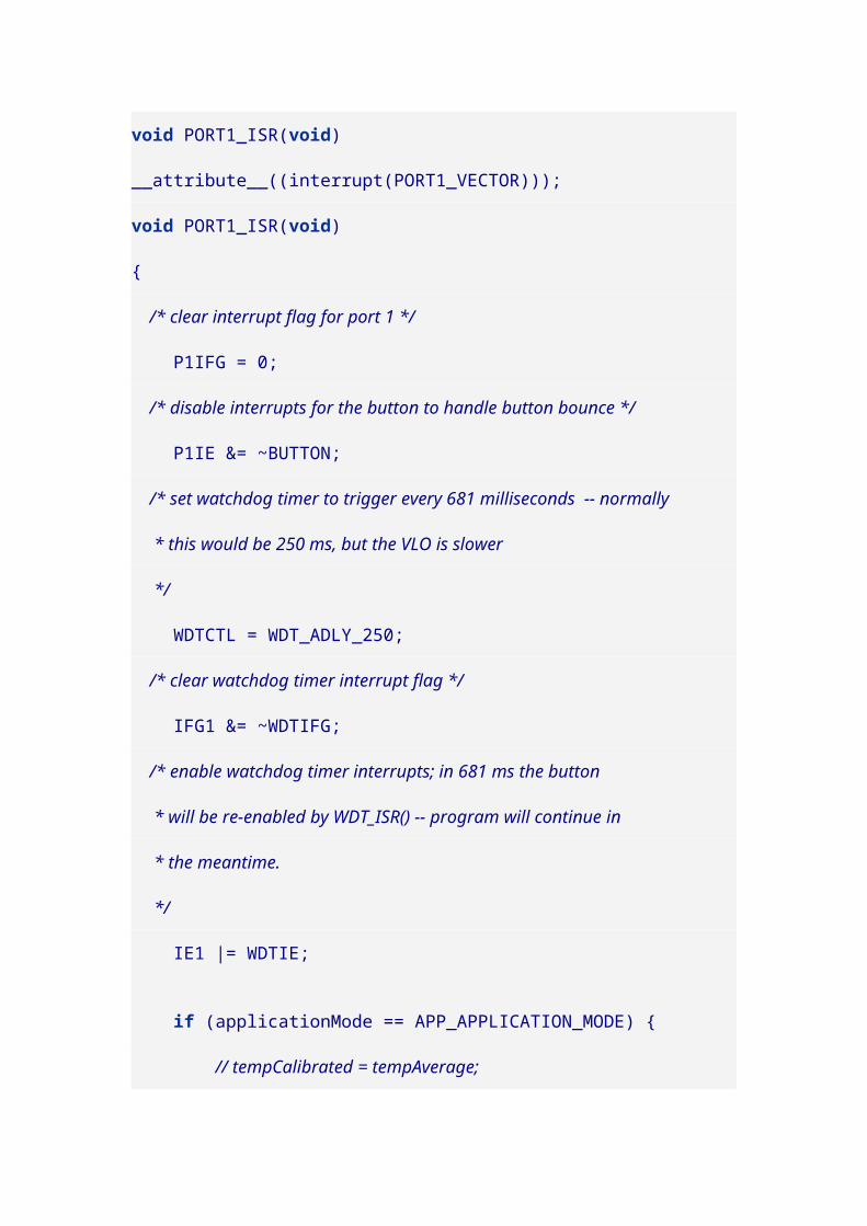
0x30, // Unsynchronized transfers 0x18, // Blink off 0x11, // Display on 0x15, // Segment Decoder ON 0x20, // Clear Data and pointer 0x00 // Clear blink memory };
P1OUT |= CD; // set for commands
spi_IO( data, sizeof(data));}
/* Prints a string on the LCD panel using the 7 segment decoder. * Understood characters are 0x00 (zero) to 0x09 (nine) and * 0x0A to 0x0F (the symbols -, E, C, =, and space). */void print_lcd( unsigned char data[], int n ) { unsigned char copy[12]; unsigned char tmp; int i;
if( n < 1 ) return; if( n > 12 ) n=12;
// The panel expects data arranged right to left, so we'll // reverse the array of data passed before writing it out. for( i = n; i > 0; i-- ) { copy[n-i] = data[i-1]; }
P1OUT &= ~CD; // set for data
spi_IO( copy, n );}
/* Draws a decimal point n places from the right, by turning on * the individual LCD segment (OR 0x8 mask with segment memory). */void decimal_on( int n ) { unsigned char data[] = { 0x14, // Segment Decoder off 0xE0+2*n, // Set pointer 0 (plus 2 for each digit) 0xB8, // Decimal point on (OR 0x8 with memory contents)

0x15 // Segment Decoder on };
if( n < 0 || n > 11 ) return;
P1OUT |= CD; // set for commands
spi_IO( data, sizeof(data));}
/* Erases a decimal point n places from the right, by turning off * the individual LCD segment (AND 0x7 mask with segment memory). */void decimal_off( int n ) { unsigned char data[] = { 0x14, // Segment Decoder off 0xE0+2*n, // Set pointer 0 (plus 2 for each digit) 0x97, // Decimal point off (AND 0x7 with memory contents) 0x15 // Segment Decoder on };
if( n < 0 || n > 11 ) return;
P1OUT |= CD; // set for commands
spi_IO( data, sizeof(data));}
/* Writes a custom configuration of segments in the digit n places from * the right, by writing 8 bits directly to the segment memory. * Mask values: * 0x01 = top 0x10 = top-left * 0x02 = top-right 0x20 = middle * 0x04 = bottom-right 0x40 = bottom-left * 0x08 = decimal 0x80 = bottom */void write_segments( int n, unsigned char bits ) { unsigned char data[] = { 0x14, // Segment Decoder off 0xE0+2*n, // Set pointer 0 (plus 2 for each digit) 0xD0+(bits&0xF),// Write contents (4 bits) 0xD0+(bits>>4), // Write contents (4 bits) 0x15 // Segment Decoder on

};
P1OUT |= CD; // set for commands
spi_IO( data, sizeof(data));}
/* Blinks a custom configuration of segments in the digit n places from * the right, by writing 8 bits directly to the blink memory. Segments * only blink if they are set, and if the blink state is set on. * Mask values: * 0x01 = top 0x10 = top-left * 0x02 = top-right 0x20 = middle * 0x04 = bottom-right 0x40 = bottom-left * 0x08 = decimal 0x80 = bottom */void write_blinking( int n, unsigned char bits ) { unsigned char data[] = { 0x14, // Segment Decoder off 0xE0+2*n, // Set pointer 0 (plus 2 for each digit) 0xC0+(bits&0xF),// Write contents (4 bits) 0xC0+(bits>>4), // Write contents (4 bits) 0x15 // Segment Decoder on };
P1OUT |= CD; // set for commands
spi_IO( data, sizeof(data));}
/* Send the command to enable blinking. (Only segments set in blink * memory actually blink, and only if they are on in segment memory.) */void blink_on() { unsigned char cmd = 0x1A;
P1OUT |= CD; // set for commands
spi_IO( &cmd, 1 );}
/* Send the command to disable blinking. */

void blink_off() { unsigned char cmd = 0x18;
P1OUT |= CD; // set for commands
spi_IO( &cmd, 1 );}
/* Send the command to clear the blink memory. */void clear_blinking() { unsigned char cmd = 0x00;
P1OUT |= CD; // set for commands
spi_IO( &cmd, 1 );}
/* Send the command to turn clear the display. */void clear_lcd() { unsigned char cmd = 0x20;
P1OUT |= CD; // set for commands
spi_IO( &cmd, 1 );}
/* Send the command to turn off the display. */void display_off() { unsigned char cmd = 0x10;
P1OUT |= CD; // set for commands
spi_IO( &cmd, 1 );}
/* Send the command to turn on the display. */void display_on() { unsigned char cmd = 0x11;
P1OUT |= CD; // set for commands
spi_IO( &cmd, 1 );}

void main( void ) { // Stop the watchdog timer so it doesn't reset our chip WDTCTL = WDTPW + WDTHOLD;
// These are the pins we need to drive. P1DIR |= SCK + MOSI + CS + CD;
// De-select the LCD panel and set the clock high P1OUT |= CS + SCK;
// Pause so everything has time to start up properly. __delay_cycles( 15000 );
// Initialize the LCD panel. init_lcd();
// Print a message. print_lcd("\x0A\x0B\x0C\x0D\x0F", 5 );
clear_lcd();
// Print 1234.5 print_lcd("\1\2\3\4\5", 5 ); decimal_on( 1 );
for( ;; ) { __bis_SR_register( LPM3_bits + GIE ); }}
The commands for building and installing this program
(using the msp430-gcc 4.5.3 compiler) are:
$ msp430-gcc -O2 -mmcu=msp430g2211 -o ktm-s1201.elf ktm-s1201.c$ mspdebug rf2500 "prog ktm-s1201.elf"
2. SPI communications with EA DOGS102 LCD panel
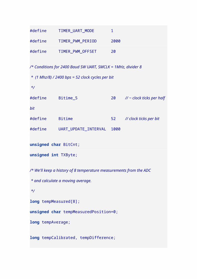
I had so much fun learning SPI that I decided to attack
another LCD panel I have on hand, an EA DOGS102. This is
a 102x64 pixel graphical panel. The data
sheet, data/dogs102-6e.pdf (page 4), is pretty clear about
wiring up the display, which requires three 1uF capacitors
for the voltage booster and a pull-up resistor (I used a 10k
resistor) for the reset pin.
There are 4 more connections for the serial communication,
and these are the hookups that correspond to the program
that follows.
LCD pin 24 SDA — Launchpad P1.1
LCD pin 25 SCK — Launchpad P1.2
LCD pin 26 C/D — Launchpad P1.7
LCD pin 28 CS — Launchpad P1.5

The dangling orange wire in the picture is hooked to the
reset pin. If I need to reset the LCD, I can just touch it
temporarily to ground.
The following code uses bit-banged SPI to initialize the
panel and fill the LCD alternately with black, then white,
then black, then white pixels. More info about the LCD
controller is in the data sheet, data/uc1701.pdf.

#include <msp430g2211.h>
#define CS BIT5 // Chip Select line#define CD BIT7 // Command/Data mode line#define MOSI BIT1 // Master-out Slave-in#define SCK BIT2 // Serial clock
#if 20110706 > __MSPGCC__/* A crude delay function. */void __delay_cycles( unsigned long int n ) { volatile unsigned int i = n/6; while( i-- ) ;}#endif
/* Write data to slave device. Since the LCD panel is * write-only, we don't worry about reading any bits. * Destroys the data array (normally received data would * go in its place). */void spi_IO( unsigned char data[], int bytes ) { int i, n;
// Set Chip Select low, so LCD panel knows we are talking to it. P1OUT &= ~CS; __delay_cycles( 5 );
for( n = 0; n < bytes; n++ ) { for( i = 0; i < 8; i++ ) { // Put bits on the line, most significant bit first. if( data[n] & 0x80 ) { P1OUT |= MOSI; } else { P1OUT &= ~MOSI; } data[n] <<= 1;
// Pulse the clock low and wait to send the bit. According to // the data sheet, data is transferred on the rising edge. P1OUT &= ~SCK; __delay_cycles( 5 );
// Send the clock back high and wait to set the next bit. Normally

// we'd also read the data bits here, but the LCD is write-only. P1OUT |= SCK; __delay_cycles( 5 ); } }
// Set Chip Select back high to finish the communication. P1OUT |= CS;}
/* Sets the LCD to command mode, and sends a 7-byte * sequence to initialize the panel. */void init_lcd( void ) { unsigned char data[] = { 0x40, // display start line 0 0xA1, // SEG reverse 0xC0, // Normal COM0-COM63 0xA4, // Disable->Set All Pixel to ON 0xA6, // Display inverse off 0xA2, // Set Bias 1/9 (Duty 1/65) 0x2F, // Booster, Regulator and Follower on 0x27, 0x81, // Set contrast 0x10, 0xFA, // Set temp compensation ... 0x90, // ... curve to -0.11 %/degC 0xAF // Display On };
P1OUT &= ~CD; // set for commands
spi_IO( data, sizeof(data));}
/* Writes zeros to the contents of display RAM, effectively resetting * all of the pixels on the screen. The screen width is 6*17 = 102 pixels, * so I used and array of size 17 and loop 6 times. Each page in RAM * spans 8 pixels vertically, and looping through the 8 pages covers * the 8*8 = 64 pixel height of the display. */void write_zeros( void ) { unsigned char zeros[17]; int i, j, page;
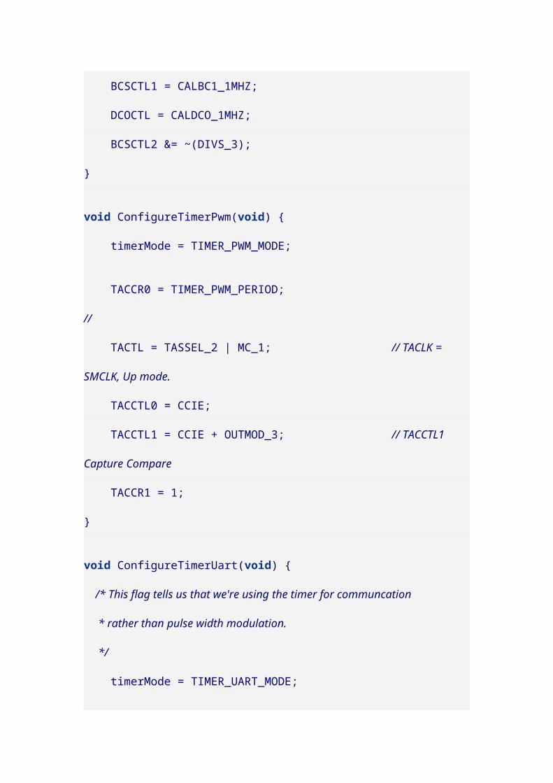
for( page = 0; page < 8; page++ ) { P1OUT &= ~CD; // set for commands zeros[0] = 0xB0 + page; // set page zeros[1] = 0x00; // LSB of column address is 0 zeros[2] = 0x10; // MSB of column address is 0 spi_IO( zeros, 3 );
P1OUT |= CD; // set for data for( i = 0; i < 6; i++ ) { for( j = 0; j < 17; j++ ) zeros[j] = 0x00;
spi_IO( zeros, sizeof( zeros )); } }}
/* Writes ones to the contents of display RAM, effectively setting * all of the pixels on the screen. The screen width is 6*17 = 102 pixels, * so I used and array of size 17 and loop 6 times. Each page in RAM * spans 8 pixels vertically, and looping through the 8 pages covers * the 8*8 = 64 pixel height of the display. */void write_ones( void ) { unsigned char ones[17]; int i, j, page;
for( page = 0; page < 8; page++ ) { P1OUT &= ~CD; // set for commands ones[0] = 0xB0 + page; // set page ones[1] = 0x00; // LSB of column address is 0 ones[2] = 0x10; // MSB of column address is 0 spi_IO( ones, 3 );
P1OUT |= CD; // set for data for( i = 0; i < 6; i++ ) { for( j = 0; j < 17; j++ ) ones[j] = 0xFF;
spi_IO( ones, sizeof( ones )); } }}
void main( void ) {

// Stop the watchdog timer so it doesn't reset our chip WDTCTL = WDTPW + WDTHOLD;
// These are the pins we need to drive. P1DIR |= SCK + MOSI + CS + CD;
// De-select the LCD panel and set the clock high. P1OUT |= CS + SCK;
// Pause so everything has time to start up properly. __delay_cycles( 5500 );
// Initialize the LCD panel. init_lcd();
// Blacken and clear the LCD two times. write_ones(); write_zeros(); write_ones(); write_zeros();
for( ;; ) { __bis_SR_register( LPM3_bits + GIE ); }}
The commands for building and installing this program
(using the msp430-gcc 4.5.3 compiler) are:
$ msp430-gcc -O2 -mmcu=msp430g2211 -o dog-s102.elf dog-s102.c$ mspdebug rf2500 "prog dog-s102.elf"
Maybe more experiments will follow. Since the DOGS102
doesn’t have a character generator, you’ll probably want to
use a chip that has more than 2K of flash (i.e. the
msp430g2211 wouldn’t be a great choice). You’ll need the
space to hold something of a font.

A chip like the msp430g2553 would probably be better, if
you intend to stick to through-hole DIP chips, and in that
case you could also do much better than bit-banging the
interface since you could use the USCI interface in the
microcontroller. There are many capable chips if you don’t
mind a harder soldering job or if surface mount is
acceptable for you.
3. USI/SPI communications with EA DOGS102 LCD panel
Bit-banging SPI communication is pretty easy, but in
general it’s not a great approach. In particular, blowing
time in a wait loop tends to consume a lot more power than
is really necessary. It would be much better to sleep and let
one of the MSP430 clocks handle communication timing.
So I decided to rewrite my DOGS102 program to use the
USI interface of the msp430g2231 chip (and similar). I had
to give up on the msp430g2211 since it doesn’t have
hardware serial support.
If I had planned ahead, I would have carried out my initial
bit-bang experiments using the data and clock pins of the

USI interface. But I didn’t so I had to re-wire my LCD panel
to my Launchpad.
The new connections are:
LCD pin 24 SDA — Launchpad P1.6
LCD pin 25 SCK — Launchpad P1.5
LCD pin 26 C/D — Launchpad P1.2
LCD pin 28 CS — Launchpad P1.1
The primary changes to the program are:
1. In spi_IO(), instead of bit banging, we load bytes into
the serial register and sleep while the data sends.
2. In the main() function, we set up the clocks and
registers for the USI (universal serial interface).
3. There is a new interrupt handler USI_ISR(), which
wakes up the main program after each byte has been
transmitted.
#include <msp430g2231.h>#include <legacymsp430.h>
/* For USI, these are the required pin assignments: * P1.5 SCLK -- serial clock * P1.6 SDO -- serial data out (MOSI for master) * P1.7 SDI -- serial data in (MISO for master) not connected * in this program. * Chip Select line can be anything. * Command/Data line can be anything. */

#define CS BIT1 // Chip Select line#define CD BIT2 // Command/Data mode line
#if 20110706 > __MSPGCC__/* A crude delay function. */void __delay_cycles( unsigned long int n ) { volatile unsigned int i = n/6; while( i-- ) ;}#endif
/* Write data to slave device. Since the LCD panel is * write-only, we don't worry about reading any bits. */void spi_IO( unsigned char data[], int bytes ) { int i, n;
// Set Chip Select low, so LCD panel knows we are talking to it. P1OUT &= ~CS;
for( n = 0; n < bytes; n++ ) { USISRL = data[n]; // load byte into USI serial register (lower half) USICNT = 8; // set count to 8 bits __bis_SR_register( LPM0_bits + GIE ); // sleep until done }
// Set Chip Select back high to finish the communication. P1OUT |= CS;}
/* Sets the LCD to command mode, and sends a 7-byte * sequence to initialize the panel. */void init_lcd( void ) { unsigned char data[] = { 0x40, // display start line 0 0xA1, // SEG reverse 0xC0, // Normal COM0-COM63 0xA4, // Disable->Set All Pixel to ON 0xA6, // Display inverse off 0xA2, // Set Bias 1/9 (Duty 1/65) 0x2F, // Booster, Regulator and Follower on 0x27, // Set... 0x81, // ...

0x10, // ...contrast. 0xFA, // Set temp compensation... 0x90, // ...curve to -0.11 %/degC 0xAF // Display On };
P1OUT &= ~CD; // set for commands
spi_IO( data, sizeof(data));}
/* Writes zeros to the contents of display RAM, effectively resetting * all of the pixels on the screen. The screen width is 6*17 = 102 pixels, * so I used and array of size 17 and loop 6 times. Each page in RAM * spans 8 pixels vertically, and looping through the 8 pages covers * the 8*8 = 64 pixel height of the display. */void write_zeros( void ) { unsigned char zeros[17]; int i, j, page;
for( page = 0; page < 8; page++ ) { P1OUT &= ~CD; // set for commands zeros[0] = 0xB0 + page; // set page zeros[1] = 0x00; // LSB of column address is 0 zeros[2] = 0x10; // MSB of column address is 0 spi_IO( zeros, 3 );
P1OUT |= CD; // set for data for( i = 0; i < 6; i++ ) { for( j = 0; j < 17; j++ ) zeros[j] = 0x00;
spi_IO( zeros, sizeof( zeros )); } }}
/* Writes ones to the contents of display RAM, effectively setting * all of the pixels on the screen. The screen width is 6*17 = 102 pixels, * so I used and array of size 17 and loop 6 times. Each page in RAM * spans 8 pixels vertically, and looping through the 8 pages covers * the 8*8 = 64 pixel height of the display. */void write_ones( void ) {

unsigned char ones[17]; int i, j, page;
for( page = 0; page < 8; page++ ) { P1OUT &= ~CD; // set for commands ones[0] = 0xB0 + page; // set page ones[1] = 0x00; // LSB of column address is 0 ones[2] = 0x10; // MSB of column address is 0 spi_IO( ones, 3 );
P1OUT |= CD; // set for data for( i = 0; i < 6; i++ ) { for( j = 0; j < 17; j++ ) ones[j] = 0xFF;
spi_IO( ones, sizeof( ones )); } }}
void main( void ) { // Stop the watchdog timer so it doesn't reset our chip WDTCTL = WDTPW + WDTHOLD;
// These are the pins we need to drive. P1DIR = CS + CD;
// Pins to enable: // P1.6 -- SDO/MOSI Master-out Slave-In // P1.5 -- SCLK serial clock // Flags: // most significant bit sent first // enable output // disable USI (for now) USICTL0 = USIPE6 | USIPE5 | USIMST | USIOE | USISWRST;
// enable interrupts, but set the interrupt flag for now USICTL1 = USIIE | USIIFG;
// Clock speed: // Use clock divider 2^4=16. // Use clock source 2 (submain clock?). // Polarity and phase settings/flags for the clock: // SPI Mode 0 --- CPOL=0,CPHA=0 --- USICKPH // SPI Mode 1 --- CPOL=0,CPHA=1 --- 0
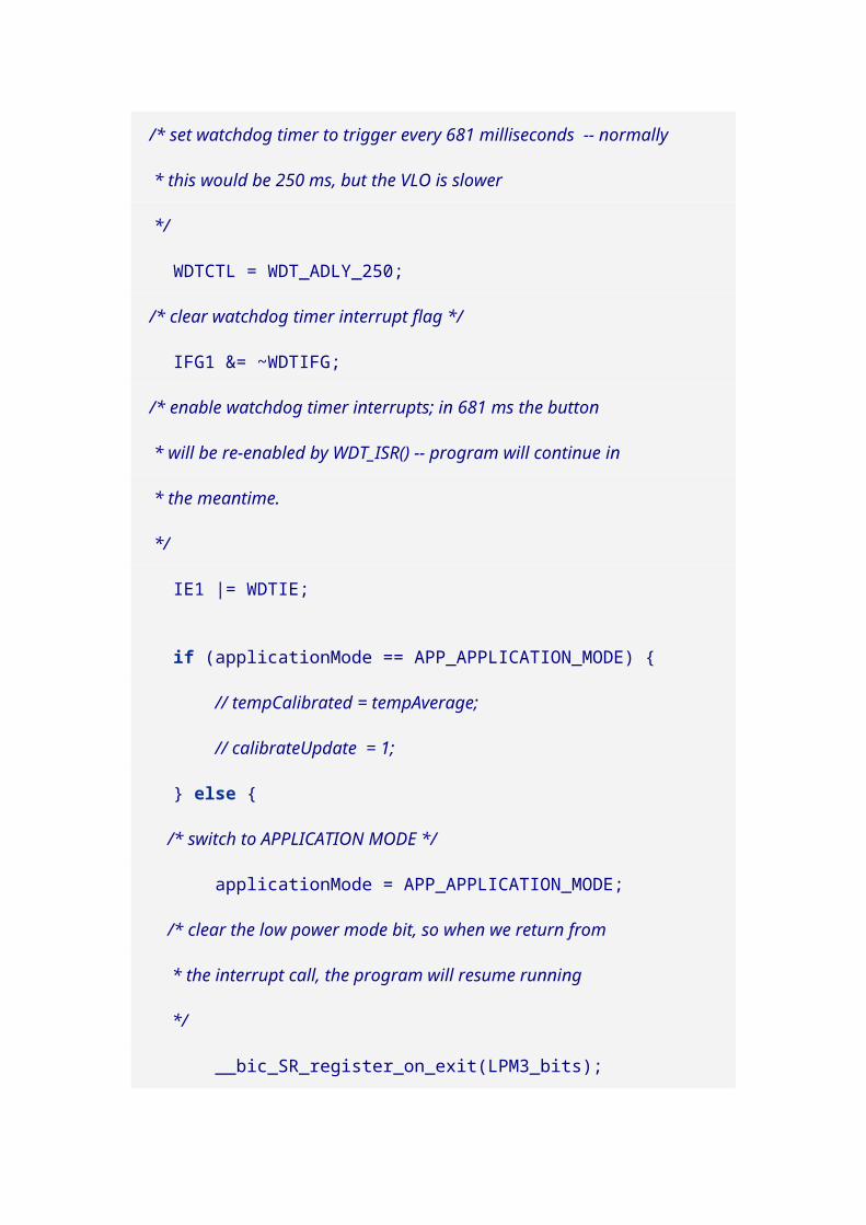
// SPI Mode 2 --- CPOL=1,CPHA=0 --- USICKPL|USICKPH // SPI Mode 3 --- CPOL=1,CPHA=1 --- USICKPL *** this one for DOGS panel USICKCTL = USIDIV_4 | USISSEL_2 | USICKPL;
// enable USI USICTL0 &= ~USISWRST;
// Clear the USI interrupt flag USICTL1 &= ~USIIFG;
// Pause so everything has time to start up properly. __delay_cycles( 5500 );
// Initialize the LCD panel. init_lcd();
// Blacken and clear the LCD two times. write_ones(); write_zeros(); write_ones(); write_zeros();
for( ;; ) { __bis_SR_register( LPM3_bits + GIE ); }}
/* This interrupt triggers when the USI serial register gets * empty. We use it to wake up the main program. */interrupt(USI_VECTOR) USI_ISR(void) { USICTL1 &= ~USIIFG; // clear the interrupt flag __bic_SR_register_on_exit( LPM0_bits ); // wake on exit}
The commands for building and installing this program
(using the msp430-gcc 4.5.3 compiler) are:
$ msp430-gcc -O2 -mmcu=msp430g2231 -o dog-s102-usi.elf dog-s102-usi.c$ mspdebug rf2500 "prog dog-s102-usi.elf"Last updated 2012-03-13 06:56:24 CDT

25. Morse Code on the MSP430
My attempt an an iambic keyer: cw.html
Morse Code With the MSP430Don Bindner<[email protected]>Table of Contents
1. Capacitive Touch
2. A Completely Minimal Paddle
3. An Iambic Keyer
4. A Standalone Keyer
5. Commercial circuit board
6. A simple straight key
7. Touch paddles
This page is a companion page for my MSP430
Launchpad page.
After learning how to do capacitive touch sensing with an
MSP430 over at lcd_i2c.html#_capacitive_touch, I started
thinking about something fun I might do with the technique.

I thought it might be fun to make a paddle keyer for keying
Morse code, so I copied the relevant parts of that page
here.
1. Capacitive Touch
Newer MSP430 chips have touch-enabled pins on them. But
I discovered while searching for information, that any
MSP430 can be programmed to do capacitive touch. This
document was very helpful in working out the
technique: MSP430 touch pad experiments.pdf. I also found
the discussion of sampling from this page helpful: Sample
Rate Jittering.
The idea for measuring a capacitive touch plate is pretty
straightforward. You just apply a voltage to it and see how
long it takes to charge. Apply ground and see how long it
takes to discharge. If the time increases, the capacitance
has gone up (and that’s what happens when you touch the
plate).
If you wire things correctly, a pair of pins on the MSP430
can monitor a pair of touch plates (which don’t have to be
anything special, basically anything metal you can touch).

For the examples that follow, I chose pins 1.4 and 1.7 on
the MSP430. The configuration is simple. Connect the pins
with a large value resistor; typical values I found in reading
were 5M ohms and 5.1M ohms. Then connect a lead from
pin 1.4 to one plate, and from pin 1.7 to another plate.
2. A Completely Minimal Paddle
You can make a completely minimal touch paddle with only
a single 5M ohm resistor and no plates at all. Bend the
leads out, and connect pin 1.4 to pin 1.7, with the resistor
straddling the MSP430. I took a picture of mine. I used a
10M ohm resistor here, since that is what I had on hand,
but I would guess that value is a bit higher that optimal. It
worked, but it seemed just a bit slow to recognize touches
when I played with it.

This program implements the touch detection. It simply
lights one LED if you press the "dot" lead (traditionally, the
left paddle). And it lights the other when you press the
"dash" lead. I could perhaps modify it later to use a
transistor, or maybe an optical isolator, to actually drive the
keyer in my transmitter. And of course, I could connect it to
real paddles.

#include <msp430g2211.h>
#define RED BIT0#define GRN BIT6
#define DOT BIT4#define DASH BIT7
volatile unsigned int timer_count;
/* This triggers when a pad has been charged or discharged. When it returns, * timer_count will hold the elapsed count of charging or discharging time for * the key. Setup for triggering this interrupt happens in * measure_key_capacitance(). */void Port_1 (void) __attribute__((interrupt(PORT1_VECTOR)));void Port_1 (void) { P1IFG = 0; timer_count = TAR - timer_count; __bic_SR_register_on_exit( LPM0_bits );}
/* Returns a value the reflects the capacitance of one of two key pads * connected by a large value resistor. Assumes key to be BIT4 or BIT7. */unsigned int measure_key_capacitance( unsigned int key ) { static unsigned int sum;
P1OUT &= ~(BIT4 + BIT7); // Start with both keys low.
/* charge key */ P1OUT |= key; asm( "nop \n\t" "nop \n\t" "nop \n\t" );
/* Set up interrupt to trigger on key. */ P1IES |= key; // Trigger on voltage drop. P1IE |= key; // Interrupt on. P1DIR &= ~key; // Float key and let voltage drop.
timer_count = TAR; // Get timer (to compare with in interrupt). __bis_SR_register( LPM0_bits + GIE ); // Sleep.

P1IE &= ~key; // Disable interrupts on key. P1OUT &= ~key; // Discharge key by setting P1DIR |= key; // active low.
sum = timer_count; // Save the count that was recorded in interrupt.
/* Charge the complement line. */ P1OUT |= (BIT4 + BIT7)^key; asm( "nop \n\t" "nop \n\t" "nop \n\t" );
/* Set up interrupt to trigger on key. */ P1IES &= ~key; // Trigger on voltage rise. P1IE |= key; // Interrupt on. P1DIR &= ~key; // Float key and let voltage rise.
timer_count = TAR; // Get timer (to compare with in interrupt). __bis_SR_register( LPM0_bits + GIE );
P1IE &= ~key; // Disable interrupts on key. P1OUT &= ~(BIT4 + BIT7); // Set both keys to P1DIR |= (BIT4 + BIT7); // active low.
return sum + timer_count; // Return the sum of both counts.}
/* Computes a trimmed mean of 18 capacitance values, trimming the largest and * smallest samples. */unsigned int sample_key( unsigned char key ) { int i, j, small, large, cap; long int total;
total = 0;
/* Measure once to initialize max and min values. */ small = large = measure_key_capacitance( key );
/* Seventeen more samples happen here. Each time we decide whether the new * sample is kept or if it replaces one of the extremes. */ for( i = 1; i < 18; i++ ) { cap = measure_key_capacitance( key ); if( cap < small ) {
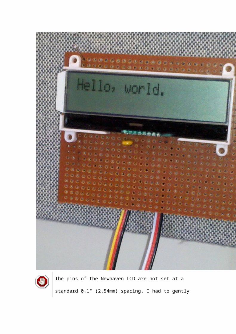
total += small; small = cap; } else if( cap > large ) { total += large; large = cap; } else { total += cap; }
// Add some jitter here, for more effective sampling. for( j=0; j < (cap&0x0F); j++ ) asm( "nop \n\t" ); }
/* We average 16 values (not including the two extremes) */ return total >> 4;}
void WDT(void) __attribute__((interrupt(WDT_VECTOR)));void WDT(void) { /* Wake up the main program. */ __bic_SR_register_on_exit( LPM0_bits );}
int main(void) { int i, j; int flag1=0, flag2=0; int baseline1=0, baseline2=0, samp1, samp2;
/* Stop the watchdog timer so it doesn't reset our chip. */ WDTCTL = WDTPW + WDTHOLD;
/* Set clock speed at 1Mhz. */ BCSCTL1 = CALBC1_1MHZ; DCOCTL = CALDCO_1MHZ;
/* Both LEDs are output lines */ P1DIR |= RED + GRN;
/* Setup for capacitive touch. Timer A is in count up mode, driven by the * submain clock (1 Mhz) with a clock divider of 2^2=4. The pins for our * touch pads are set as output pins. */

TACTL = MC_2 + TASSEL_2 + ID_2; // count up mode, SMCLK, /4 P1DIR |= DASH + DOT;
/* Get maximum baseline values for each key. In the main loop, more than * 125% of the baseline value will indicate a touch event. */ P1OUT |= RED + GRN; // Visually signal the calibration cycle. for( i = 0; i < 32; i++ ) { samp1 = sample_key(DASH); if( samp1 > baseline1 ) baseline1 = samp1;
samp2 = sample_key(DOT); if( samp2 > baseline2 ) baseline2 = samp2; } P1OUT &= ~(RED + GRN); // Lights off, calibration done.
while( 1 ) { WDTCTL = WDTPW + WDTHOLD; // hold watchdog clock
samp1 = sample_key(DASH); samp2 = sample_key(DOT);
/* One paddle lights the green light. */ if( 4*samp1 > 5*baseline1 ) { P1OUT |= GRN; } else { P1OUT &= ~GRN; }
/* The other paddle lights the red. */ if( 4*samp2 > 5*baseline2 ) { P1OUT |= RED; } else { P1OUT &= ~RED; }
/* Set watchdog timer interval to wake us up in 0.5 ms. */ WDTCTL = WDT_MDLY_0_5; IE1 |= WDTIE; /* Go to sleep to save power until awoken by timer. */ __bis_SR_register(LPM0_bits); }}

The key to the program is
the measure_key_capacitance() function. It actually takes two
measures of the capacitance of the key; and you get to
specify the key, either BIT4 or BIT7. First it charges the
key, then measures the time for it to discharge through the
5M ohm resistor (by recording the value of a timer and
setting an interrupt to trigger on Port 1 when the voltage
has fallen). Then it takes a second reading by discharging
the pin, and then charging the plate from the other pin
through the same resister (again measuring the time with
the Port 1 interrupt handler). The sum of the charge and
discharge times becomes our measure of capacitance.
The capacitance values can fluctuate quite a bit, and I read
about a couple of different compensating techniques.
Effectively, everyone recommends some kind of low pass
filter (i.e. code that will minimize the effects of high-
frequency oscillations). I tried many different things, but I
eventually settled on a trimmed mean. It’s very easy to
understand, and it gave me consistent performance.
The sample_key() function simply measures the capacitance
of the same key 18 times in succession. It throws out the

lowest and highest values and averages the other 16. One
other line worth noting in that function is the inner loop
of nop instructions. The idea of that is to randomize slightly
when the samples are drawn, following ideas of: Sample
Rate Jittering.
One other thing that I’ve done here is find the largest of a
series of samples for the initial baselines, rather than just
taking a single average. That seems to reduce the number
of instances where the paddles are just too sensitive (and
react to anything coming even near them).
3. An Iambic Keyer
First, it should be said that I’ve never actually used an
electronic keyer, except the one I made for this project. I’m
still a pretty new ham. So I don’t know if my keyer behaves
in ways that experienced hams would appreciate.
There are a few things that I can note readily. The top
speed of this keyer is probably fairly limited. I might be able
to do better by raising the clock speed to 16mhz, but I
haven’t tried that. Speed is probably more fundamentally
limited by the time it takes to measure a capacitance.

Another thing to note, is that this keyer does not have a
"dot buffer." That is to say, if it is playing a dash and you hit
a dot (quickly) in the middle, it will not be remembered. Of
course, if you keep the dot keyed, it will be picked up when
the dash is finished. I toyed with adding a dot buffer, but it
isn’t really compatible with my idea for this program.
For this program, I wanted something I could practice on.
That is, I wanted to be able to key the paddles, and hear the
appropriate result. And I wanted to do it with a minimum of
parts (two paddles, one resistor, one salvaged
electromagnetic transducer, and one Launchpad).
Doing anything while sound is playing creates easily
discernible distortion in the tone. For a "real" keyer, where
you aren’t trying to play your own sound, but rather where
you key an actual radio it could probably be done fine. It
would also be not too hard to hook two launchpads
together, and let one do the keying and the other create
sound (or use a 555 timer, or whatever).
I’ve coded it for the transducer to be hooked between pin
P1.1 and ground. I used the red LED to give a visual
indicator of inter-letter space, and the green LED to give a

visual indicator of word space (so if you see the green light
appear between letters instead of words, you are keying too
slowly).
The configuration for the touch paddles is:
A 5M ohm resistor between pin 1.4 and pin 1.7.
Pin 1.4 is connected to the paddle that creates dots
(usually the left).
Pin 1.7 is connected to the paddle that creates dashes
(usually the right).
I connected a transducer that I salvaged from a broken
cordless phone (a SoniCrest HC12G pulled from a Uniden
phone) between pin 1.1 and ground (with a resistor to keep
the volume down so my wife doesn’t go nuts). Jameco
part #138722 looks like a good match, though I haven’t
tried it.
A little hot glue, and a couple of scrap wood block put
together a fairly clean keyer. I found that a couple of rubber
bands around the ends of the base made for really good
"non-slip feet." Enjoy a picture:

#include <msp430g2211.h>
#define AUDIO BIT1#define RED BIT0#define GRN BIT6
#define DOT BIT4#define DASH BIT7
unsigned int wpm = 8;unsigned int dotCount = 0, guardSpace = 0;
volatile unsigned int timer_count;
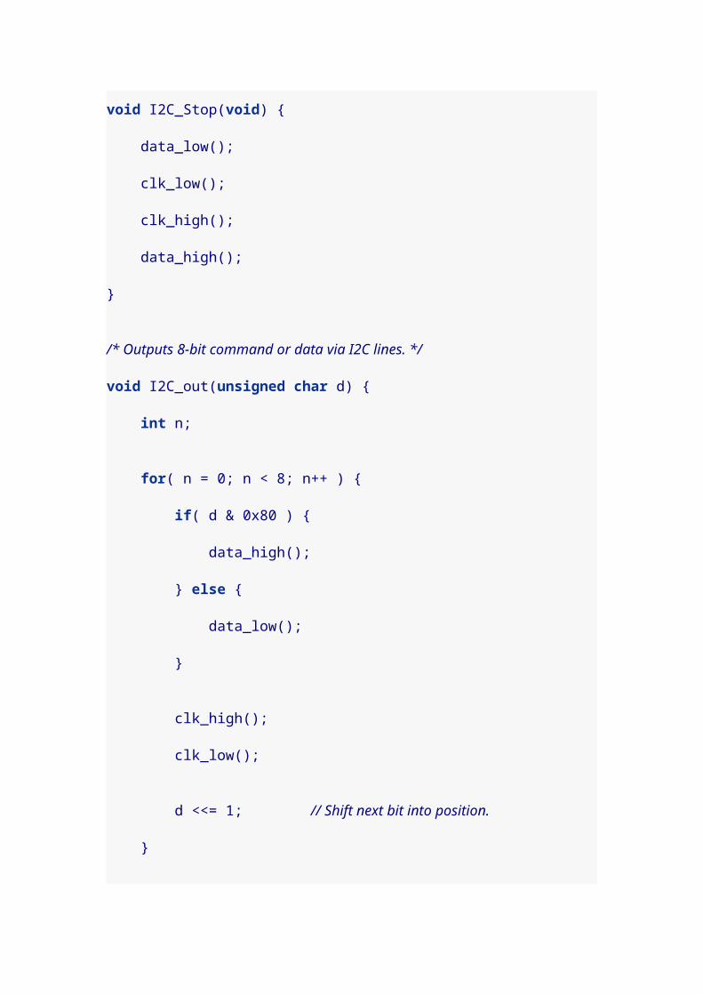
volatile int counter = 0;volatile unsigned int countAdjust=0;volatile int toneOn = 0;
volatile int dotKey = 0, dashKey = 0;
/* Key capacitance baseline values. */unsigned int base_dash, base_dot;
/* State of the keyer. * idle: no keys pressed recently * dot: sent a dot * dash: sent a dash */enum STATES { idle, dot, dash } state = idle;
/* This triggers when a pad has been charged or discharged. When it returns, * timer_count will hold the elapsed count of charging or discharging time for * the key. Setup for triggering this interrupt happens in * measure_key_capacitance(). */void Port_1 (void) __attribute__((interrupt(PORT1_VECTOR)));void Port_1 (void) { P1IFG = 0; timer_count = TAR - timer_count; __bic_SR_register_on_exit( LPM0_bits );}
/* Returns a value the reflects the capacitance of one of two key pads * connected by a large value resistor. Assumes key to be BIT7 or BIT4. */unsigned int measure_key_capacitance( unsigned int key ) { static unsigned int sum;
P1OUT &= ~(BIT7 + BIT4); // Start with both keys low.
/* charge key */ P1OUT |= key; asm( "nop \n\t" "nop \n\t" "nop \n\t" );
/* Set up interrupt to trigger on key. */ P1IES |= key; // Trigger on voltage drop.
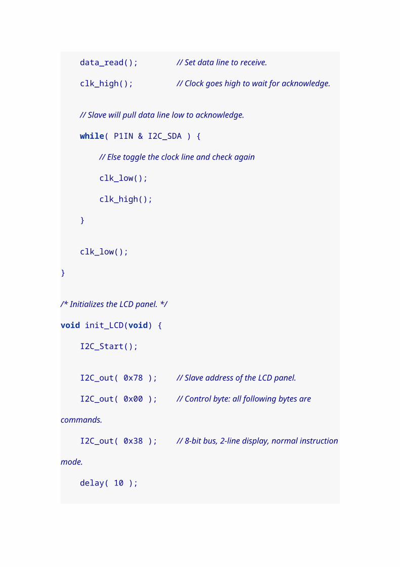
P1IE |= key; // Interrupt on. P1DIR &= ~key; // Float key and let voltage drop.
timer_count = TAR; // Get timer (to compare with in interrupt). __bis_SR_register( LPM0_bits + GIE ); // Sleep.
P1IE &= ~key; // Disable interrupts on key. P1OUT &= ~key; // Discharge key by setting P1DIR |= key; // active low.
sum = timer_count; // Save the count that was recorded in interrupt.
/* Charge the complement line. */ P1OUT |= (BIT7 + BIT4)^key; asm( "nop \n\t" "nop \n\t" "nop \n\t" );
/* Set up interrupt to trigger on key. */ P1IES &= ~key; // Trigger on voltage rise. P1IE |= key; // Interrupt on. P1DIR &= ~key; // Float key and let voltage rise.
timer_count = TAR; // Get timer (to compare with in interrupt). __bis_SR_register( LPM0_bits + GIE );
P1IE &= ~key; // Disable interrupts on key. P1OUT &= ~(BIT7 + BIT4); // Set both keys to P1DIR |= (BIT7 + BIT4); // active low.
return sum + timer_count; // Return the sum of both counts.}
/* Computes a trimmed mean of 18 capacitance values, trimming the largest and * smallest samples. */unsigned int sample_key( unsigned char key ) { long int total; int i, j, small, large, cap;
total = 0;
/* Measure once to initialize max and min values. */ small = large = measure_key_capacitance( key );

/* Seventeen more samples happen here. Each time we decide whether the new * sample is kept or if it replaces one of the extremes. */ for( i = 1; i < 18; i++ ) { cap = measure_key_capacitance( key ); if( cap < small ) { total += small; small = cap; } else if( cap > large ) { total += large; large = cap; } else { total += cap; }
// Add some jitter here, for more effective sampling. for( j=0; j < (cap&0x0F); j++ ) asm( "nop \n\t" ); }
/* We average 16 values (not including the two extremes) */ return total >> 4;}
/* Returns 1 if the key is touched (sufficiently past the baseline * value) and 0 otherwise. Sampling can take a fair bit of time, so * we adjust the counter for timerA. */int key_touched( unsigned char key, unsigned int baseline ) { unsigned int timeElapsed=0; int touch;
/* Time elapsed is computed to adjust the delay time. */ timeElapsed = TAR;
touch = ( 4*sample_key(key) > 5*baseline );
/* Adjust the delay to account for key sampling time. */ countAdjust += TAR - timeElapsed;
return touch;}
/* This interrupt counts the durations for playing dots and dashes, * as well as the durations for dot-spaces and dash-spaces. */void TimerA0(void) __attribute__((interrupt(TIMERA0_VECTOR)));

void TimerA0(void) { CCR0 += 80;
if( countAdjust >= 80 ) { counter -= countAdjust/80; countAdjust = countAdjust%80; }
if( counter-- > 0 ) { if( toneOn ) { P1OUT ^= AUDIO; } } else { /* Wake up main program when count is finished. */ __bic_SR_register_on_exit(LPM0_bits); }}
void WDT(void) __attribute__((interrupt(WDT_VECTOR)));void WDT(void) { /* wake up the main program. */ __bic_SR_register_on_exit(LPM3_bits);}
void do_space_with_polling( int guard, int minwait, int maxwait ) { /* Waits the specified amount of time with polling at 4 points, at * the beginning, at the end of the guard time, at the end of the minwait * and at the end of the maxwait. Guard space keeps us from accidentally * adding another symbol, but a dash is fine after a dot, and a dot is fine * after a dash. Assumes guard <= minwait <= maxwait.*/
if( guard > 0 ) { /* Immediately poll for a key, guarding against doubles. */ if( state != dash ) { dashKey = key_touched(DASH, base_dash); }
if( state != dot ) { dotKey = key_touched(DOT, base_dot); }

if( dotKey || dashKey ) { maxwait = minwait; // Return as soon as possible. }
// Sleep past the guard time. counter = guard; CCR0 = TAR+80; // 80 * 4us = 320us -- for tone generation (for delay here) CCTL0 |= CCIE; __bis_SR_register(LPM0_bits + GIE); CCTL0 &= ~CCIE; }
if( minwait > guard ) { /* Guard time has passed. Poll for a key. */ if( !( dotKey || dashKey )) { dashKey = key_touched(DASH, base_dash); dotKey = key_touched(DOT, base_dot);
if( (state == dot) && dashKey ) { // Make sure both keys alternates. dotKey = 0; }
if( dotKey || dashKey ) { maxwait = minwait; // Return as soon as possible. } }
// Sleep past the minwait time. counter = minwait - guard; CCR0 = TAR+80; // 80 * 4us = 320us -- for tone generation (for delay here) CCTL0 |= CCIE; __bis_SR_register(LPM0_bits + GIE); CCTL0 &= ~CCIE; }
if( maxwait > minwait ) { /* Minwait time has passed. Poll for a key. */ if( !( dotKey || dashKey )) { dashKey = key_touched(DASH, base_dash);

dotKey = key_touched(DOT, base_dot);
if( dotKey || dashKey ) { return; } }
// Sleep to the maxwait time. counter = maxwait - minwait; CCR0 = TAR+80; // 80 * 4us = 320us -- for tone generation (for delay here) CCTL0 |= CCIE; __bis_SR_register(LPM0_bits + GIE); CCTL0 &= ~CCIE; }
/* Maxwait time has passed. Poll for a key. */ if( !( dotKey || dashKey )) { dashKey = key_touched(DASH, base_dash); dotKey = key_touched(DOT, base_dot); }}
void play_welcome( char *str ) { CCR0 = TAR+80; CCTL0 |= CCIE; // CCR0 interrupt enabled
while( *str ) { toneOn = 1; counter = ( *str == '-' ) ? 3*dotCount : dotCount; __bis_SR_register(LPM0_bits + GIE);
P1OUT &= ~AUDIO;
toneOn = 0; counter = dotCount; __bis_SR_register(LPM0_bits + GIE); str++; }
CCTL0 &= ~CCIE;}
int main(void) {
int i, j; int flag1=0, flag2=0; unsigned int samp1, samp2;
/* Stop the watchdog timer so it doesn't reset our chip. */ WDTCTL = WDTPW + WDTHOLD; /* Set ACLK to use VLO so we can sleep in LPM3 when idle. */ BCSCTL3 |= LFXT1S_2;
/* Set all output pins low. */ P1OUT = 0x00; P1DIR = 0xFF;
/* Set clock speed at 1Mhz. */ BCSCTL1 = CALBC1_1MHZ; DCOCTL = CALDCO_1MHZ;
/* Both LEDs are output lines */ P1DIR |= RED + GRN; P1OUT &= ~(RED + GRN);
/* So is the Audio pin. */ P1DIR |= AUDIO; P1OUT &= ~AUDIO;
/* One word per minute is 50 dots, which makes each dot 6/5 seconds. Since * there are 1e6/4 clock ticks per second (because of the clock divider), * and the counter is moved every 80 ticks, the length of a 1 wpm dot is * 1e6/4/80*(6/5) = 3750. */ dotCount = 3750 / wpm; guardSpace = dotCount/2; // guard space is 1/2 of a dot
/* Setup for capacitive touch. Timer A is in count up mode, driven by the * submain clock (1 Mhz) with a clock divider of 2^2=4. The pins for our * touch pads are set as output pins. Same settings used for tone generation. */ TACTL = MC_2 + TASSEL_2 + ID_2 + TACLR; // count up mode, SMCLK, /4

play_welcome("-.-."); // "C"
/* Get maximum baseline values for each key. In the main loop, more than * 125% of the baseline value will indicate a touch event. */ for( i = 0; i < 32; i++ ) { samp1 = sample_key(DASH); if( samp1 > base_dash ) base_dash = samp1;
samp2 = sample_key(DOT); if( samp2 > base_dot ) base_dot = samp2; }
play_welcome("--.-"); // "Q"
while( 1 ) { if( !( dotKey || dashKey )) { /* One paddle sends dashes. */ dashKey = key_touched(DASH, base_dash); /* The other paddle sends dots. */ dotKey = key_touched(DOT, base_dot); }
if( dotKey ) { state = dot;
counter = dotCount; toneOn = 1; // Play tone.
countAdjust = 0; // no need to adjust during tone CCR0 = TAR+80; // 80 * 4us = 320us -- for tone generation CCTL0 |= CCIE; // CCR0 interrupt enabled __bis_SR_register(LPM0_bits + GIE); CCTL0 &= ~CCIE; // CCR0 interrupt disabled } else if( dashKey ) { state = dash;
counter = 3*dotCount; toneOn = 1; // Play tone.
countAdjust = 0; // no need to adjust during tone CCR0 = TAR+80; // 80 * 4us = 320us -- for tone generation CCTL0 |= CCIE; // CCR0 interrupt enabled

__bis_SR_register(LPM0_bits + GIE); CCTL0 &= ~CCIE; // CCR0 interrupt disabled } else { /* Set watchdog timer interval to wake us up in 43.7 ms * (normally it would be 16 ms, but the VLO is slower). */ WDTCTL = WDT_ADLY_16; IE1 |= WDTIE; /* Go to sleep to save power until awoken by timer. */ __bis_SR_register(LPM3_bits + GIE); /* Hold the watchdog clock. */ WDTCTL = WDTPW + WDTHOLD; continue; }
dotKey = dashKey = 0;
/* Need at least a dot-space now, maybe more. */ toneOn = 0; P1OUT &= ~AUDIO;
/* 0. Keys within this first space will add symbols to the current letter. * We'll guard for dots after a dot, and dashes after a dash. We'll accept * (sloppy) keys up to half a dot late. */ do_space_with_polling( guardSpace, dotCount, dotCount+dotCount/2 );
/* If a key was pressed, go back to the top to process it. */ if( dotKey || dashKey ) continue;
state = idle;
P1OUT |= RED; // visually indicate dash space between letters
/* 1.5 Now we finish the dash space, and start a new letter. No guard time. * We'll accept (keys) up to half a dot late, for starting the next letter. */ do_space_with_polling( 0, dotCount+dotCount/2, 2*dotCount );
P1OUT &= ~RED; // end of dash space
/* If a key was pressed, go back to the top to process it. */

if( dotKey || dashKey ) continue;
/* 3.5 Another three and a half dots finishes the word space. Start with * two and a half dots without polling. */
P1OUT |= GRN; // visually indicate word space
counter = 2*dotCount+ dotCount/2; CCR0 = TAR+80; // 80 * 4us = 320us -- for tone generation (for delay here) CCTL0 |= CCIE; // CCR0 interrupt enabled __bis_SR_register(LPM0_bits + GIE); CCTL0 &= ~CCIE; // CCR0 interrupt disabled
P1OUT &= ~GRN; // visually indicate ready again
/* 7. A final dot space finishes the word-space. */ do_space_with_polling( 0, dotCount, dotCount );
/* Idle. Loop back to the top. */ }}
I poll at select times, measured from the ending time of the
previous dot or dash: after 0 dots of space, 0.5 dots, 1 dot,
1.5 dots, 3 dots, 3.5 dots, 6 dots, and 7 dots. It might make
the keyer more responsive to poll more often, but I found it
tricky to get that just right.
You should see a red light between letters, and a red-green
transition between words. If you see the green between
letters, or a red between symbols in the same letter, you are
keying too slowly. If you fail to see a red between letters, or
a green between words, you are keying too quickly.

(If you don’t have a speaker/transducer to connect to pin
1.1, change AUDIO to BIT0 or BIT6 and it will light one of
the LEDs instead.)
4. A Standalone Keyer
It took me some missteps, but I really wanted to make my
keyer free-standing, without the need for the Launchpad
card. The page Design notes: Power was really helpful.
They aren’t kidding about the capacitors, by the way.
Without the proper filtering capacitors, my program would
refuse to run, hang randomly, etc. A bunch of caps are
definitely going into my next component order.
I took a bit of time to rebuild this as a stand-alone circuit,
and I added 3 LEDs to my circuit board. One is tied to the
audio pin, and glows as code is generated. The other two
show the inter-letter and inter-word spaces. On my board, I
chose green for the code light, amber for inter-letter space,
and red for inter-word space.
The jumper in the picture is for turning off the speaker, so it
doesn’t drive my wife nuts. I can still test without sound by
watching the LEDs. For paddles, I eventually settled on PCI

expansion bay covers salvaged from a broken PC. They
worked fine, although it was a bit hard to get solder to stick
to them.
To summarize:
P1.0 is connected to amber LED (for showing inter-
letter space) and 100 ohm current limiting resistor.
P1.1 is connected to green LED and 100 ohm current
limiting resistor, as well as to the transducer. (The
transducer is connected through a jumper so it can be
turned off.)
P1.6 is connected to red LED (for showing inter-word
space) and 100 ohm current limiting resistor.
P1.7 is connected to DASH paddle.
P1.4 is connected to DOT paddle.
(I used the same 100 ohm resistor for all 3 LEDs putting it
between the cathode and ground, and tying all the cathodes
together.)
Other connections that were needed:
Vcc is connected to the positive terminal of a two AA
battery pack.

GND is connected to the negative terminal of a two AA
pack.
Vcc and GND are connected to each other by 0.1uF
capacitor.
RST is connected to Vcc through a 47K resistor.
RST is connected to GND through a 0.001uF
capacitor.

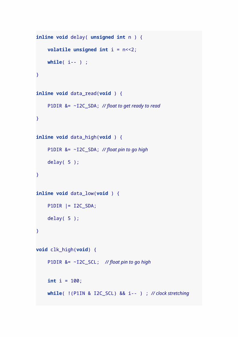
When idle, the circuit measures a current draw of 50 uA
which means it should run for over a year on a pair of AA
batteries, even if on all the time. You’d probably want to
turn it off and on to recalibrate, at least when there are
significant temperature or humidity changes. When being
keyed, it probably draws closer to 15-20mA for lighting the
LEDs and playing the buzzer.

5. Commercial circuit board
I decided that I wanted to do up a circuit board for keyer
project. It seems that part of the advantage of using a
microcontroller is that you can customize your programs to
suit different needs. For example, perhaps you only need a
really nice touch interface, but your intent is to interface to
a ham radio that already has a keyer. In that case you can
trim all of the unnecessary program parts and focus on
making clean and responsive touch paddle code. Perhaps
you want to go even simpler and use it as a straight key.
I tried to plan my board so that it could be used in many
different ways. It came back from the fab and it looks pretty
nice. So far, I’ve written a couple of
different simplifiedprograms to run on it.

Here’s the board fully populated with components.
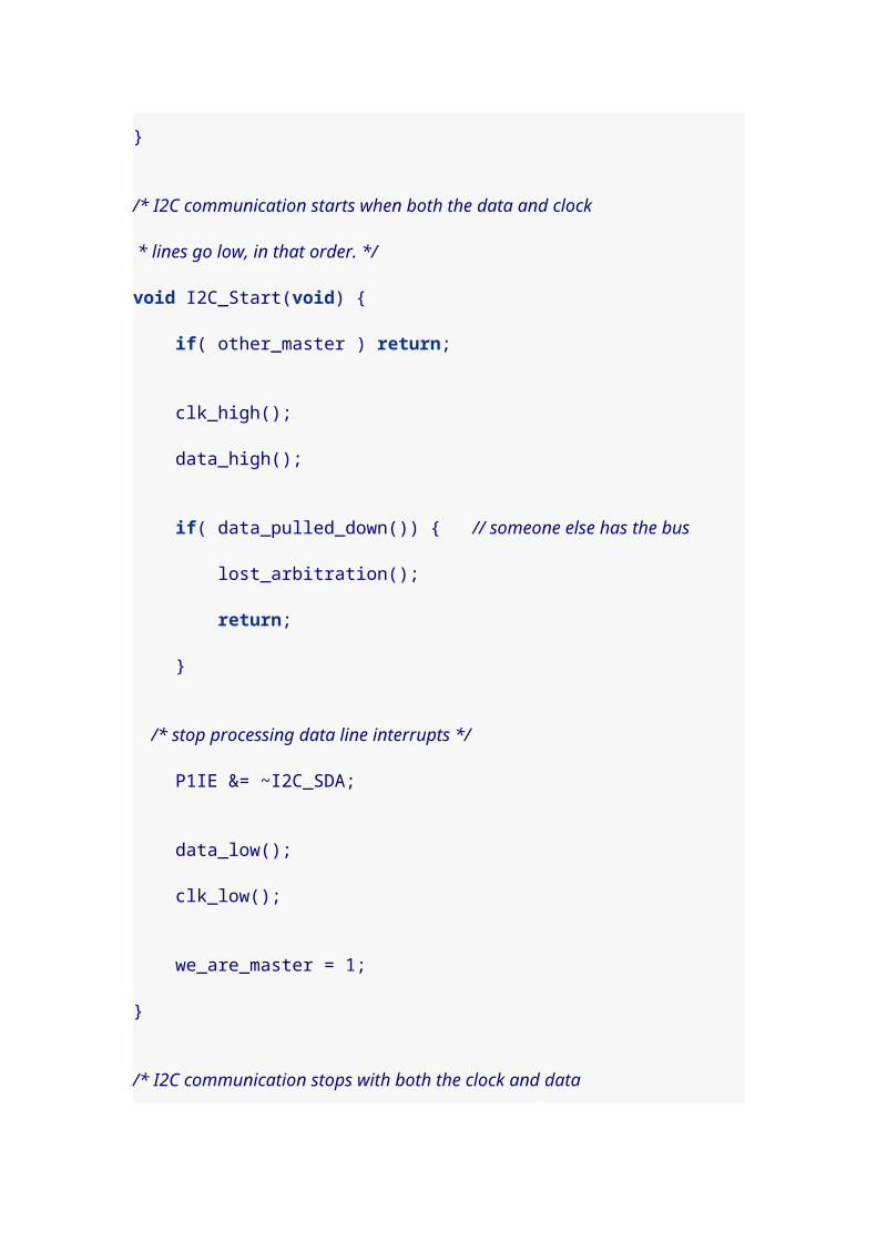
I did the board design using CadSoft Eagle. A schematic
and board file are here: keyer.sch keyer.brd.
This is the component list:
1. U$1 is a MS430g2211 microcontroller (but the
MSP430g2231 or other similar chips should also
work).
2. C1 is a 0.1uF capacitor
3. C2 is a 0.001uF (1 nanofarad) capacitor

4. R1 and R6 are 49k ohm resistors
5. R2 is a 100 ohm resistor
6. R3 is a 5M ohm resistor
7. R4 and R5 are 56 ohm resistors
8. RED, YEL, GRN are 3mm LEDs
9. OK1 is an MCT61 optoisolator
10. SG1 is a magnetic transducer (sourced from Jameco)
11. Terminal blocks are TE Connectivity 282834-2 and
282834-3.
Jumper JP2 lets you connect or disconnect the
speaker/transducer. Jumper JP1 allows you to program the
MSP430 "in place" without having to always remove the
chip to a Launchpad card. Simply provide power, then
jumper these three lines to a Launchpad for programming.
6. A simple straight key
Probably the conceptually simplest way to run morse code
is via a "straight key." In the context of our paddle circuit
touching a paddle (either one) will close the key. That’s
what the next program achieves, with little fuss. It assumes
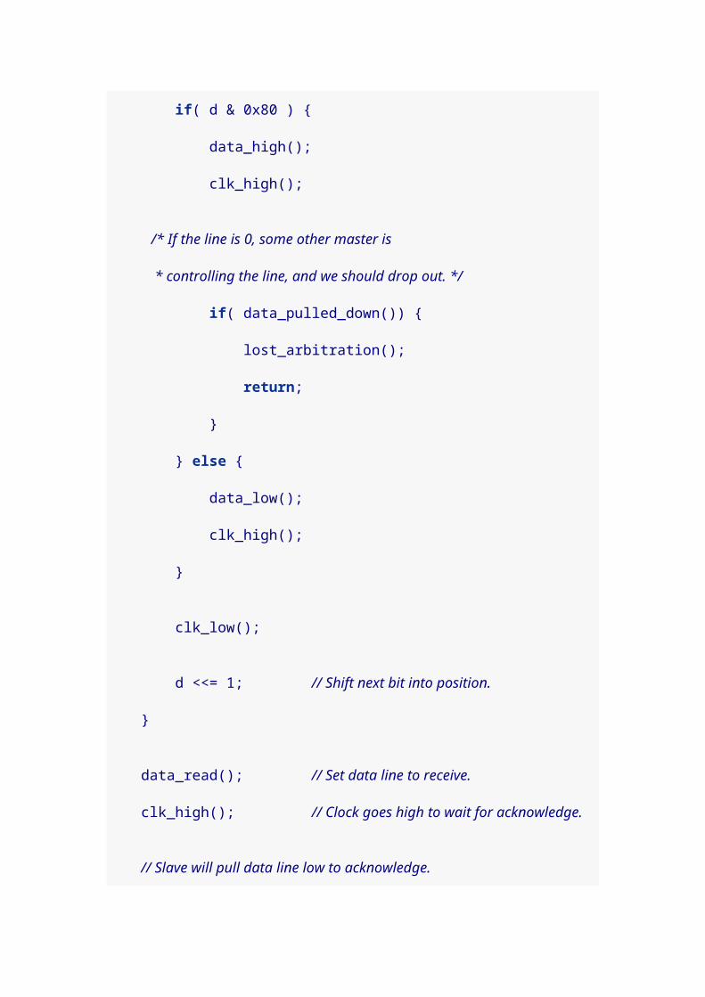
that any side tone will be generated by your radio, and you
only wish the microcontroller to handle the opening and
closing of the key.
Many of the components of the board are optional if you
want to create a minimal straight key. These are the
components you need:
1. U$1: MS430g2211 microcontroller (but the
MSP430g2231 or other similar chips should also
work).
2. C1: 0.1uF capacitor
3. C2: 0.001uF (1 nanofarad) capacitor
4. R1: 49k ohm resistor
5. R3: 5M ohm resistor
6. R4, R5: 56 ohm resistors
7. OK1: MCT61 optoisolator
8. X1, X2, X3: 282834-2 and 282834-3 (or just solder
connections straight to the pads).
You’ll need a way to get the signal into you radio. My Yaesu
radio uses a mini stereo connector, so I connected the S, R,
and T lines of X3 to the sleeve, ring, and tip of a stereo

connector. Then I used a stereo patch cable to connect my
radio. Technically, for a straight key, you may not need to
connect the ring part of the connection.
You may optionally want to include the yellow and red LEDs
and the 100 ohm resistor R3, but the program works fine
without them. Here’s the code.
#include <msp430g2211.h>
#define YEL BIT0#define RED BIT6
#define DOT BIT4#define DASH BIT5
#define TIP BIT2#define RING BIT3
volatile unsigned int timer_count;
/* Key capacitance baseline values. */unsigned int base_dash, base_dot;
/* This triggers when a pad has been charged or discharged. When it returns, * timer_count will hold the elapsed count of charging or discharging time for * the key. Setup for triggering this interrupt happens in * measure_key_capacitance(). */void Port_1 (void) __attribute__((interrupt(PORT1_VECTOR)));void Port_1 (void) { P1IFG = 0; timer_count = TAR - timer_count; __bic_SR_register_on_exit( LPM0_bits );}
/* Returns a value the reflects the capacitance of one of two key pads

* connected by a large value resistor. Assumes key to be DOT or DASH. */unsigned int measure_key_capacitance( unsigned int key ) { static unsigned int sum;
P1OUT &= ~(DOT + DASH); // Start with both keys low.
/* charge key */ P1OUT |= key; asm( "nop \n\t" "nop \n\t" "nop \n\t" );
/* Set up interrupt to trigger on key. */ P1IES |= key; // Trigger on voltage drop. P1IE |= key; // Interrupt on. P1DIR &= ~key; // Float key and let voltage drop.
timer_count = TAR; // Get timer (to compare with in interrupt). __bis_SR_register( LPM0_bits + GIE ); // Sleep.
P1IE &= ~key; // Disable interrupts on key. P1OUT &= ~key; // Discharge key by setting P1DIR |= key; // active low.
sum = timer_count; // Save the count that was recorded in interrupt.
/* Charge the complement line. */ P1OUT |= (DOT + DASH)^key; asm( "nop \n\t" "nop \n\t" "nop \n\t" );
/* Set up interrupt to trigger on key. */ P1IES &= ~key; // Trigger on voltage rise. P1IE |= key; // Interrupt on. P1DIR &= ~key; // Float key and let voltage rise.
timer_count = TAR; // Get timer (to compare with in interrupt). __bis_SR_register( LPM0_bits + GIE );
P1IE &= ~key; // Disable interrupts on key. P1OUT &= ~(DOT + DASH); // Set both keys to P1DIR |= (DOT + DASH); // active low.
return sum + timer_count; // Return the sum of both counts.}

/* Computes a trimmed mean of 18 capacitance values, trimming the largest and * smallest samples. */unsigned int sample_key( unsigned char key ) { long int total; int i, j, small, large, cap;
total = 0;
/* Measure once to initialize max and min values. */ small = large = measure_key_capacitance( key );
/* Seventeen more samples happen here. Each time we decide whether the new * sample is kept or if it replaces one of the extremes. */ for( i = 1; i < 18; i++ ) { cap = measure_key_capacitance( key ); if( cap < small ) { total += small; small = cap; } else if( cap > large ) { total += large; large = cap; } else { total += cap; }
// Add some jitter here, for more effective sampling. for( j=0; j < (cap&0x0F); j++ ) asm( "nop \n\t" ); }
/* We average 16 values (not including the two extremes) */ return total >> 4;}
/* Returns 1 if the key is touched (sufficiently past the baseline * value) and 0 otherwise. */inline int key_touched( unsigned char key, unsigned int baseline ) { return ( 4*sample_key(key) > 5*baseline );}
void WDT(void) __attribute__((interrupt(WDT_VECTOR)));
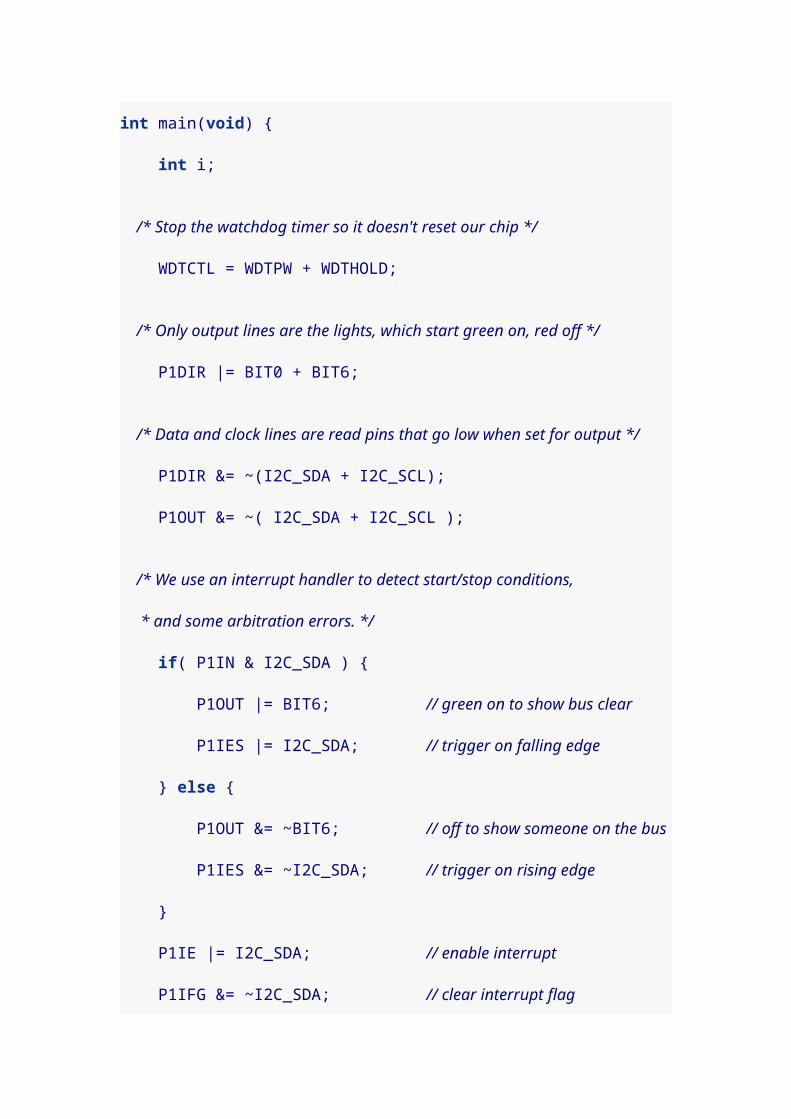
void WDT(void) { /* wake up the main program. */ __bic_SR_register_on_exit(LPM3_bits);}
int main(void) { int i; unsigned int samp1, samp2;
/* Stop the watchdog timer so it doesn't reset our chip. */ WDTCTL = WDTPW + WDTHOLD; /* Set ACLK to use VLO so we can sleep in LPM3 when idle. */ BCSCTL3 |= LFXT1S_2;
/* Set all output pins low. */ P1OUT = 0x00; P1DIR = 0xFF;
/* Set clock speed at 1Mhz. */ BCSCTL1 = CALBC1_1MHZ; DCOCTL = CALDCO_1MHZ;
/* Both LEDs are output lines */ P1DIR |= YEL + RED; P1OUT &= ~(YEL + RED);
/* Setup for capacitive touch. Timer A is in count up mode, driven by the * submain clock (1 Mhz) with a clock divider of 2^2=4. The pins for our * touch pads are set as output pins. */ TACTL = MC_2 + TASSEL_2 + ID_2 + TACLR; // count up mode, SMCLK, /4
P1OUT |= YEL + RED; /* Get maximum baseline values for each key. In the main loop, more than * 125% of the baseline value will indicate a touch event. */ for( i = 0; i < 32; i++ ) { samp1 = sample_key(DASH); if( samp1 > base_dash ) base_dash = samp1;
samp2 = sample_key(DOT); if( samp2 > base_dot ) base_dot = samp2;

} P1OUT &= ~(YEL + RED);
while( 1 ) { if( key_touched( DASH, base_dash ) || key_touched( DOT, base_dot )) { P1OUT |= TIP+RING + YEL+RED; } else { P1OUT &= ~(TIP+RING + YEL+RED); }
/* Set watchdog timer interval to wake us up in 5.2 ms * (normally it would be 1.9 ms, but the VLO is slower). */ WDTCTL = WDT_ADLY_1_9; IE1 |= WDTIE; /* Go to sleep to save power until awoken by timer. */ __bis_SR_register(LPM3_bits + GIE); /* Hold the watchdog clock. */ WDTCTL = WDTPW + WDTHOLD; }}
The function of this program is not hard to understand.
When the capacitive touch code detects that you’ve touched
a paddle, it raises the output lines that go to the input side
of the optoisolator. That causes the resistance in
the output side of the optoisolator to fall, and
the ring and tip connections are brought to ground (exactly
as if you closed a physical key/switch). That triggers your
radio to generate continuous wave (i.e. Morse code) signal.
When you quit touching the paddles, the microcontroller
drops its output lines and the optoisolator resistance
recovers (as if a physical key/switch were opened).

7. Touch paddles
Only slightly more complex than a straight key, two paddles
allows you to connect to a radio and separately indicate
dots and dashes. This requires essentially the same
components as the straight key:
1. U$1: MS430g2211 microcontroller (but the
MSP430g2231 or other similar chips should also
work).
2. C1: 0.1uF capacitor
3. C2: 0.001uF (1 nanofarad) capacitor
4. R1: 49k ohm resistor
5. R3: 5M ohm resistor
6. R4, R5: 56 ohm resistors
7. OK1: MCT61 optoisolator
8. X1, X2, X3: 282834-2 and 282834-3 (or just solder
connections straight to the pads).
You’ll need a way to get the signal into you radio, just as
with the straight key version of the program. My Yaesu
radio uses a mini stereo connector, so I connected the S, R,
and T lines of X3 to the sleeve, ring, and tip of a stereo

connector. Then I used a stereo patch cable to connect my
radio. For this version of the program you will need to
connect the ring part of the connection.
You may optionally want to include the yellow and red LEDs
and the 100 ohm resistor R3, but the program works fine
without them. Also, if you include the switch, as well as 49k
ohm resistor R6, you’ll be able to reverse the function of
paddles on the fly (that is, which paddle generates dots and
which generates dashes).
Here’s the code.
#include <msp430g2211.h>
#define SWITCH BIT7
#define YEL BIT0#define RED BIT6
#define DOT BIT4#define DASH BIT5
#define TIP BIT2#define RING BIT3
volatile unsigned int timer_count;volatile unsigned int bounce_count=0;volatile unsigned int dash=DASH, dot=DOT;
/* Key capacitance baseline values. */unsigned int base_dash, base_dot;
/* This triggers when a pad has been charged or discharged. When it returns,
* timer_count will hold the elapsed count of charging or discharging time for * the key. Setup for triggering this interrupt happens in * measure_key_capacitance(). Also triggers if we press the switch, and * schedules a check of the switch after a debouncing delay. */void Port_1 (void) __attribute__((interrupt(PORT1_VECTOR)));void Port_1 (void) { if( P1IFG & SWITCH ) { P1IFG &= ~SWITCH; bounce_count = 6; }
if( P1IFG & (DOT+DASH)) { P1IFG &= ~(DOT+DASH); timer_count = TAR - timer_count; __bic_SR_register_on_exit( LPM0_bits ); }}
/* Returns a value the reflects the capacitance of one of two key pads * connected by a large value resistor. Assumes key to be DOT or DASH. */unsigned int measure_key_capacitance( unsigned int key ) { static unsigned int sum;
P1IE &= ~SWITCH; // Disable switch while we measure.
P1OUT &= ~(DOT + DASH); // Start with both keys low.
/* charge key */ P1OUT |= key; asm( "nop \n\t" "nop \n\t" "nop \n\t" );
/* Set up interrupt to trigger on key. */ P1IES |= key; // Trigger on voltage drop. P1IE |= key; // Interrupt on. P1DIR &= ~key; // Float key and let voltage drop.
timer_count = TAR; // Get timer (to compare with in interrupt). __bis_SR_register( LPM0_bits + GIE ); // Sleep.
P1IE &= ~key; // Disable interrupts on key.

P1OUT &= ~key; // Discharge key by setting P1DIR |= key; // active low.
sum = timer_count; // Save the count that was recorded in interrupt.
/* Charge the complement line. */ P1OUT |= (DOT + DASH)^key; asm( "nop \n\t" "nop \n\t" "nop \n\t" );
/* Set up interrupt to trigger on key. */ P1IES &= ~key; // Trigger on voltage rise. P1IE |= key; // Interrupt on. P1DIR &= ~key; // Float key and let voltage rise.
timer_count = TAR; // Get timer (to compare with in interrupt). __bis_SR_register( LPM0_bits + GIE );
P1IE &= ~key; // Disable interrupts on key. P1OUT &= ~(DOT + DASH); // Set both keys to P1DIR |= (DOT + DASH); // active low.
P1IE |= SWITCH; // Re-enable switch.
return sum + timer_count; // Return the sum of both counts.}
/* Computes a trimmed mean of 18 capacitance values, trimming the largest and * smallest samples. */unsigned int sample_key( unsigned char key ) { long int total; int i, j, small, large, cap;
total = 0;
/* Measure once to initialize max and min values. */ small = large = measure_key_capacitance( key );
/* Seventeen more samples happen here. Each time we decide whether the new * sample is kept or if it replaces one of the extremes. */ for( i = 1; i < 18; i++ ) { cap = measure_key_capacitance( key );

if( cap < small ) { total += small; small = cap; } else if( cap > large ) { total += large; large = cap; } else { total += cap; }
// Add some jitter here, for more effective sampling. for( j=0; j < (cap&0x0F); j++ ) asm( "nop \n\t" ); }
/* We average 16 values (not including the two extremes) */ return total >> 4;}
/* Returns 1 if the key is touched (sufficiently past the baseline * value) and 0 otherwise. */inline int key_touched( unsigned char key, unsigned int baseline ) { return ( 4*sample_key(key) > 5*baseline );}
void WDT(void) __attribute__((interrupt(WDT_VECTOR)));void WDT(void) { if( bounce_count ) { bounce_count--;
/* When count hits 0, it's time to check the switch */ if( !bounce_count ) { if( P1IN & BIT7 ) { // key press, swap dash and dot dash ^= DASH+DOT; dot ^= DASH+DOT; } } } else { /* wake up the main program. */ __bic_SR_register_on_exit(LPM3_bits); }}
int main(void) {

int i; unsigned int samp1, samp2;
/* Stop the watchdog timer so it doesn't reset our chip. */ WDTCTL = WDTPW + WDTHOLD; /* Set ACLK to use VLO so we can sleep in LPM3 when idle. */ BCSCTL3 |= LFXT1S_2;
/* Set all output pins low. */ P1OUT = 0x00; P1DIR = 0xFF;
/* Set clock speed at 1Mhz. */ BCSCTL1 = CALBC1_1MHZ; DCOCTL = CALDCO_1MHZ;
/* Both LEDs are output lines */ P1DIR |= YEL + RED; P1OUT &= ~(YEL + RED);
/* Set switch as input pin triggering on rise. */ P1IES &= ~SWITCH; // Trigger on voltage rise. P1IE |= SWITCH; // Interrupt on. P1DIR &= ~SWITCH; // Input pin.
/* Setup for capacitive touch. Timer A is in count up mode, driven by the * submain clock (1 Mhz) with a clock divider of 2^2=4. The pins for our * touch pads are set as output pins. */ TACTL = MC_2 + TASSEL_2 + ID_2 + TACLR; // count up mode, SMCLK, /4
P1OUT |= YEL + RED; /* Get maximum baseline values for each key. In the main loop, more than * 125% of the baseline value will indicate a touch event. */ for( i = 0; i < 32; i++ ) { samp1 = sample_key(DASH); if( samp1 > base_dash ) base_dash = samp1;
samp2 = sample_key(DOT); if( samp2 > base_dot ) base_dot = samp2; }

P1OUT &= ~(YEL + RED);
while( 1 ) { if( key_touched( dash, base_dash )) { P1OUT |= RING + RED; } else { P1OUT &= ~(RING + RED); }
if( key_touched( dot, base_dot )) { P1OUT |= (TIP + YEL); } else { P1OUT &= ~(TIP + YEL); }
/* Set watchdog timer interval to wake us up in 5.2 ms * (normally it would be 1.9 ms, but the VLO is slower). */ WDTCTL = WDT_ADLY_1_9; IE1 |= WDTIE; /* Go to sleep to save power until awoken by timer. */ __bis_SR_register(LPM3_bits + GIE); /* Hold the watchdog clock. */ WDTCTL = WDTPW + WDTHOLD; }}
This program functions nearly identically to the straight key
program, except for two differences.
The ring and tip connections are driven independently, and
the Port 1 interrupt handler has been adapted to detect
when the switch is pressed. A small change was also
required in the measure_key_capacitance() function to prevent
races when the switch is pressed.
Last updated 2012-01-12 00:02:46 CST

26. Recovering a FRAM Experimenter’s Board
When I had a FRAM board turn south, I programmed a
Launchpad to erase it and get things going
again: fram_bsl.html
Recovering a FRAM Experimenter’s BoardDon Bindner<[email protected]>I had a FRAM experimenter’s board that I lent to a student
for use with mspgcc4 and mspdebug. After a few hours of
work, my student informed me that the board quit working
and mspdebug presented an error about the fuse being
blown.
It seemed improbable that the fuse had become blown
(which you do by carefully flashing specific values to special
addresses in the flash memory), since we were not
experimenting with anything remotely related to fuse
setting. A few Google searches turned up this
thread, http://www.mail-archive.com/mspgcc-

[email protected]/msg10446.html,and TI tech
support suggested that I use the Boot-Strap Loader (BSL) to
reset the
chip http://www.ti.com/lit/ug/slau319a/slau319a.pdf
Since I’ve worked through UART communications with the
Launchpad at MSP430 Launchpad, it seemed obvious that
the way to recover my FRAM board is to program a
Launchpad to access the Flash BSL (detailed in Chapter 3
of the pdf) and give the Mass Erase command.
#include <msp430g2211.h>
/* FRAM experimenter Mass Erase application. Invokes the FRAM * boot-strap loader and gives the the Mass Erase command via * 9600 bps UART communication, 8 bit data, even parity, 1 stop bit. * This code requires an external clock crystal for calibration * of 4 Mhz clock speed, unless you change HAVE_CRYSTAL below. */
#define RED_LED BIT0#define GRN_LED BIT6
#define HAVE_CRYSTAL 1 // Or 0 if you don't have a clock crystal.
#define FRAM_RST BIT4 // Connect Launchpad 1.4 to FRAM RST pin.#define FRAM_TEST BIT5 // Connect Launchpad 1.5 to FRAM TEST pin.#define TXD BIT1 // Connect Launchpad 1.1 to FRAM RXD pin.#define RXD BIT2 // Connect Launchpad 1.2 to FRAM TXD pin.
/* Ticks per bit, and ticks per half. Use the following values * based on speed: 9600 bps -> 52 */#define TPB 52

#define TPH TPB/2
volatile unsigned int parity = 0;volatile unsigned int TXWord = 0;volatile unsigned int RXWord = 0;volatile unsigned int rxbitcnt = 0;volatile unsigned int txbitcnt = 0;
/* circular buffers for characters received/to send */#define BSIZE 16 // must be power of 2volatile unsigned char send_buffer[BSIZE];volatile unsigned char recv_buffer[BSIZE];volatile unsigned int sbhead=0, sbtail=0, rbhead=0, rbtail=0, bytestosend=0, bytesreceived=0;
/* function prototypes */unsigned char set_dco_c(unsigned int delta);void initUart( void );inline void RX_Start( void );unsigned char RX_Byte( void );void TX_Byte( unsigned char c );
/* A crude delay function. Tune by changing the constant. */inline void delay( unsigned int n ) { volatile unsigned int i = n<<2; while( i-- ) ;}
void main(void) { int i, n=32; unsigned char erase[] = { 0x80, 0x01, 0x00, 0x15, /* command */ 0x64, 0xA3 /* checksum */ }; unsigned char c;
/* stop the watchdog timer */ WDTCTL = WDTPW + WDTHOLD;
/* Reset and Test pins start low */ P1OUT &= ~ (FRAM_RST + FRAM_TEST); P1DIR |= FRAM_RST + FRAM_TEST; delay(n);
/* LEDs off, but we can use them for debugging if we want */

P1DIR |= RED_LED+GRN_LED; P1OUT &= ~ (RED_LED + GRN_LED );
/* set clock speed and initialize the timers and data pins */ initUart();
/* Toggle Test pin. */ P1OUT |= FRAM_TEST; delay(n); P1OUT &= ~FRAM_TEST; delay(n);
/* Transition Test then Reset in order */ P1OUT |= FRAM_TEST; delay(n); P1OUT |= FRAM_RST; delay(n); P1OUT &= ~FRAM_TEST; // final transition starts the BSL
delay(1500);
/* Start listening for data, and enable interrupts, 9600 8E1. */ RX_Start(); /**** Serial is listening from here forward. ****/ __bis_SR_register( GIE );
/* Send the Mass Erase command. */ P1OUT |= RED_LED; for( i = 0; i < sizeof( erase ); i++ ) { TX_Byte( erase[i] ); }
/* Wait for acknowledgement. */ while( ! bytesreceived ) ;
P1OUT |= GRN_LED;
c = RX_Byte(); if( c == 0x00 ) { // Response of 0x00 is success P1OUT &= ~RED_LED; }
for( ; ; ) { /* go to sleep and wait for data */

__bis_SR_register( LPM0_bits + GIE ); }}
/* Pass a delta value to set the DCO speed. Values for delta: * 244 -> 1 MHz 1220 -> 5 Mhz 2197 -> 9 Mhz 3173 -> 13 Mhz * 488 -> 2 Mhz 1464 -> 6 Mhz 2441 -> 10 Mhz 3417 -> 14 Mhz * 732 -> 3 Mhz 1708 -> 7 Mhz 2685 -> 11 Mhz 3662 -> 15 Mhz * 976 -> 4 Mhz 1953 -> 8 Mhz 2929 -> 12 Mhz 3906 -> 16 Mhz * General formula: * floor(x hz / 4096) -> delta * Return values: * 0 - DCO set * 255 - Timeout * Adapted from code by J. B. Remnant. */unsigned char set_dco_c(unsigned int delta) { unsigned int Compare, Oldcapture = 0; int direction=0; volatile int i; unsigned char signchg=0;
/* set auxiliary clock to use /8 divider (requires external crystal) */ BCSCTL1 |= DIVA_3; /* Timer A0 capture positive edge, select input 1, capture mode */ TACCTL0 = CM_1 + CCIS_1 + CAP; /* Timer A use submain clock, continuous up mode, clear timer */ TACTL = TASSEL_2 + MC_2 + TACLR; // SMCLK, cont-mode, clear
/* loop 10000 times to set clock */ for ( i = 10000; i && (signchg<3); i-- ) { while (!(CCIFG & TACCTL0)) ; // Wait until capture occurred TACCTL0 &= ~CCIFG; // Capture occurred, clear flag Compare = TACCR0; // Get current captured SMCLK Compare = Compare - Oldcapture; // SMCLK difference Oldcapture = TACCR0; // Save current captured SMCLK
if (delta == Compare) break; // If equal, leave the loop else if (delta < Compare) {
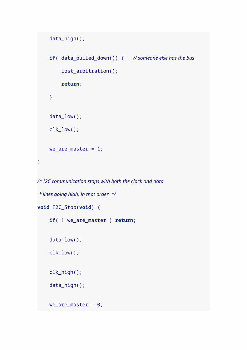
DCOCTL--; // DCO is too fast, slow it down if (DCOCTL == 0xFF) // Did DCO roll under? if (BCSCTL1 & 0x0f) BCSCTL1--; // Select lower RSEL
if( direction > 0 ) { // catch for successive direction changes signchg++; // and increment count when one happens } else { signchg=0; } direction = -1; } else { DCOCTL++; // DCO is too slow, speed it up if (DCOCTL == 0x00) // Did DCO roll over? if ((BCSCTL1 & 0x0f) != 0x0f) BCSCTL1++; // Sel higher RSEL
if( direction < 0 ) { // catch for successive direction changes signchg++; // and increment count when one happens } else { signchg=0; } direction = +1; } }
TACCTL0 = 0; // Stop TACCR0 TACTL = 0; // Stop Timer_A BCSCTL1 &= ~DIVA_3; // ACLK = LFXT1CLK
/* i>0 means that DCO is set correctly -- set return value accordingly */ Compare = (i) ? 0 : 255;
/* delay loop */ for (i = 0; i < 0x4000; i++) ;
return Compare;

}
void initUart( void ) { /* Set clock speed to 4 Mhz, no divider. */#if HAVE_CRYSTAL set_dco_c( 976 );#else /* If no crystal, this setting will probably work. */ BCSCTL1 = CALBC1_1MHZ + 4; DCOCTL = CALDCO_1MHZ;#endif BCSCTL2 &= ~(DIVS_3);
/* Set timer A to use continuous mode 4 Mhz / 8 = 500 khz. */ TACTL = TASSEL_2 + MC_2 + ID_3;
/* When TXD isn't being used, it should be set to binary 1. */ TACCTL0 = OUT;
/* TXD and RXD set for timer function, RXD input, TXD output */ P1SEL |= TXD + RXD; P1DIR &= ~ RXD; P1DIR |= TXD;}
/* This continuously sends bits of the TXWord starting from the * least significant bit (the 0 start bit). One bit is sent every * time the handler is activated. When the bits run out, a new * byte is loaded from the data pointer, until bytestosend equals 0. */void TimerA0 (void) __attribute__((interrupt(TIMERA0_VECTOR)));void TimerA0(void) { int i;
if( txbitcnt ) { /* Send least significant bit, by changing output mode to * Reset (OUTMOD0|OUTMOD2) for binary 0 and Set (OUTMOD0) for 1. */ if( TXWord & 0x01 ) { TACCTL0 &= ~OUTMOD2; } else { TACCTL0 |= OUTMOD2; } TXWord >>= 1;
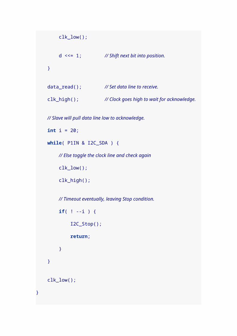
txbitcnt --; }
/* If there are no bits left, load the next byte */ if( !txbitcnt ) { if( bytestosend ) { TXWord = send_buffer[sbtail++]; sbtail &= BSIZE-1; bytestosend --;
/* Get the parity bit to make even parity. */ parity = 0; for( i = 0; i < 8; i++ ) { parity = ( parity ^ (TXWord>>i)); } parity &= 1;
/* Load next byte with even parity, 1 stop bit 0x200, and shifted * left to make the start bit. */ TXWord = ( 0x200 | (parity<<8) | TXWord ) << 1;
/* 1 start bit + 8 data bits + 1 parity + 1 stop bit */ txbitcnt = 11; } else { /* turn off interrupts if not receiving */ if( ! rxbitcnt ) TACCTL0 &= ~ CCIE; } }
/* add ticks per bit to trigger again on next bit in stream */ CCR0 += TPB; /* reset the interrupt flag */ TACCTL0 &= ~CCIFG;}
void RX_Start( void ) { /* Make ready to receive character. Synchronize, negative edge * capture, enable interrupts. */ TACCTL1 = SCS + OUTMOD0 + CM1 + CAP + CCIE;}
/* Stuffs a byte into the buffer, and schedules it to be sent. */

void TX_Byte( unsigned char c ) { if( bytestosend < BSIZE ) { send_buffer[sbhead++] = c; sbhead &= BSIZE-1; bytestosend ++; }
/* Turn on transmitting if needed. */ if( ! (TACCTL0 & CCIE)) { /* Start sending after 1 more bit of mark time. */ CCR0 = TAR + TPB; /* Transmit 1/Mark (OUTMOD0) and enable interrupts */ TACCTL0 = CCIS0 + OUTMOD0 + CCIE; }}
/* Retrieves a byte from the receive buffer. */unsigned char RX_Byte( void ) { unsigned char c = 0;
if( bytesreceived ) { c = recv_buffer[rbtail++]; rbtail &= BSIZE-1; bytesreceived --; } return c;}
void TimerA1 (void) __attribute__((interrupt(TIMERA1_VECTOR)));void TimerA1(void) { /* If we just caught the 0 start bit, then turn off capture * mode (it'll be all compares from here forward) and add * ticks-per-half so we'll catch signals in the middle of * each bit. */ if( TACCTL1 & CAP ) { /* 9 bits pending = 8 bits + 1 parity */ rxbitcnt = 9; RXWord = 0;
/* next interrupt in 1.5 bits (i.e. in middle of next bit) */ CCR1 += TPH + TPB;
/* reset capture mode and interrupt flag */

TACCTL1 &= ~ ( CAP + CCIFG );
return; }
/* Otherwise we need to catch another bit. We'll shift right * the currently received data, and add new bits on the left. */ RXWord >>= 1; if( TACCTL1 & SCCI ) { RXWord |= 0x100; } rxbitcnt --;
/* last bit received */ if( ! rxbitcnt ) { /* Record this byte and reset for next. * Put character in circular recv_buffer (unless full). */ if( bytesreceived < BSIZE ) { recv_buffer[rbhead++] = (unsigned char)RXWord; rbhead &= BSIZE-1; bytesreceived ++; }
/* we're done, reset to capture */ TACCTL1 = SCS + OUTMOD0 + CM1 + CAP + CCIE;
return; }
/* add ticks per bit to trigger again on next bit in stream */ CCR1 += TPB;
/* reset the interrupt flag */ TACCTL1 &= ~CCIFG;}
This code was designed for a Launchpad board that has the
clock crystal soldered in place (since it uses that clock to
calibrate the main system clock to 4Mhz instead of the

default 1Mhz speed). But if you don’t have a crystal, you
can change the value of HAVE_CRYSTAL to 0, and the program
will try a "best guess" that will probably work.
On your FRAM board, remove the jumpers from TXD, RXD,
RST, and TEST. You’re going to connect the "chip side" of
these jumpers to your Launchpad board. On your
Launchpad board, remove the TXD and RXD jumpers.
These are the connections to make between the boards:
FRAM TXD to Launchpad RXD (P1.2)
FRAM RXD to Launchpad TXD (P1.1)
FRAM RST to Launchpad P1.4
FRAM TEST to Launchpad P1.5
FRAM Vcc to Launchpad Vcc
FRAM GND to Launchpad GND
Connect the USB cable from your computer to your
Launchpad card, and load the program.
$ msp430-gcc -O2 -mmcu=msp430g2211 -o fram_bsl.elf fram_bsl.c
$ mspdebug rf2500 "prog fram_bsl.elf"
When the program runs on your Launchpad, you should
briefly see the red LED come on. If it was successful, the

red LED will go dark and the green LED will remain lit. At
that point, your FRAM board should be erased and ready to
use again (don’t forget to re-install the jumpers on both
boards).
I was asked by someone to provide an elf file, since
different compilers can sometimes want slightly different
source and syntax. I have generated one and uploaded it.
This one is compiled with HAVE_CRYSTAL defined to 0, so it
should work on a Launchpad with or without the clock
crystal. I believe it will work fine on an msp430g2211, an
msp430g2231, or an msp430f2012; perhaps others as well.
Download: fram_bsl.elf
Good luck.Last updated 2011-12-14 19:57:18 CST
27. Basic burglar alarm
For a pre-teenager’s bedroom: burglar.html
Last updated 2012-03-06 23:39:02 CST
Burglar alarm with keypad

Don Bindner<[email protected]>Table of Contents
1. Keypad control
When I was young, I had an electronics kit, and my favorite
circuits were the alarms. I burned out one of the transistors
in my set, so I couldn’t build the "burglar alarm" for a long
time. But, there was a light-activated alarm circuit that I
constructed over and over. I eventually learned to
substitute another part for my broken transistor, and the
burglar alarm came to be as well. I even wired it to the
screws in the latch of my door, running the wire down the
door jam and under my dresser. It worked great too, until
the batteries on the detector circuit ran down at 6am the
next morning. The separate siren circuit still had a solid set
of batteries, so everyone in the house pretty much got up
early.
My 10-year-old daughter is enamored with the idea of an
intruder alarm, so I’m back at it with my MSP430. I’m using
an msp430g2452 because it has 16 general purpose IO
pins, enough to run a keypad plus detector plus piezo
speaker plus some status LEDs.

Here’s a picture of the prototype so far:
Components in the picture:
One Radio Shack prototyping board
One Radio Shack 2-AA battery box.

One piezo speaker and transformer
from http://www.dealextreme.com/p/wireless-entry-
alarm-826
One TI MSP430G2452
One 20-pin DIP socket
One Jameco keypad (part number 2081828)
One 0.1uF capacitor (between Vcc and GND)
One 0.001uF capacitor (between RST and GND)
One 47k ohm resistor (between RST and Vcc)
Two 3mm LEDs (anodes on pins p2.6 and p2.7)
One 100 ohm resistor (between cathodes of LEDs and
GND)
One terminal block for power
1. Keypad control
My first tasks were to get the LEDs to light, and to get
usable input from the keypad. The LEDs were fairly easy
after accounting for one detail. They are hooked to p2.7 and
p2.6, but those pins also double as XIN and XOUT (if you
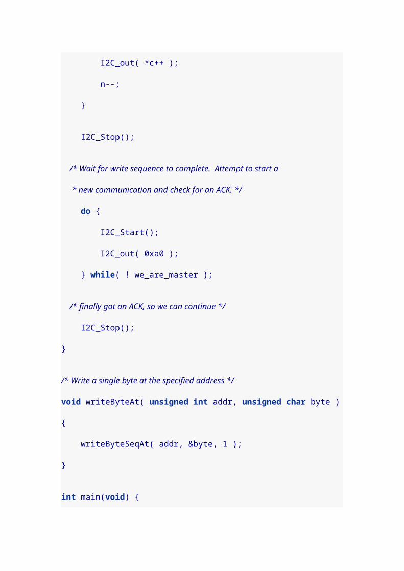
use an external clock crystal). Clearing the P2SEL bits for
those pins, changes their behavior to standard I/O pins.
They keypad was a bit more work. For one thing, it didn’t
come with any kind of data sheet or instructions. So I had to
take it apart and follow the traces to see how the 10 wires
of the keypad are controlled by the 12 keys. These are the
wire connections I discovered:
black — 1 — blue
white — 4 — blue
violet — 7 — blue
black — 2 — green
white — 5 — green
violet — 8 — green
black — 3 — yellow
white — 6 — yellow
gray — 9 — yellow
violet — 0 — yellow
orange — * — red
brown — # — red
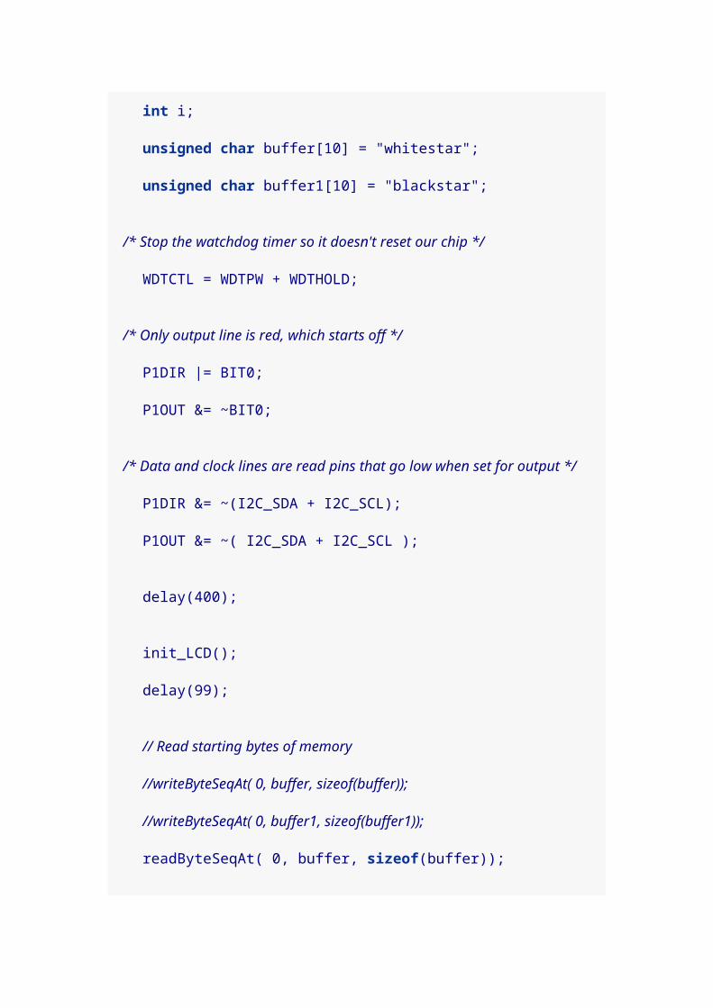
They configuration is not as efficient as it could be (3 wires
for columns and 4 wires for rows would be better), but it is
what it is. I decided to consider the 6 colors on the left of
my list to be "supply" wires, and the 4 colors on the right
are "receive" wires. I connected blue, green, yellow, and
red wires to pins on Port 2, p2.1-p2.4 respectively. That way
I can detect keypresses by asserting a voltage on one
supply wire and letting that trigger a corresponding
interrupt on the Port 2 interrupt handler. The black, white,
gray, violet, orange, and brown wires are connected,
respectively, to Port 1 pins p1.0-p1.5.
Since I envision this burglar alarm as battery powered, I’d
like it to sleep in the lowest power modes as much as
possible. For that reason, in the code that follows, I have
configured the auxilliary clock to use the Very Low-power
Oscillator (VLO), and I trigger the Watchdog timer interrupt
from that every 44 milleseconds. The Watchdog interrupt
handler charges each of the keypad supply wires briefly
(with interrupts re-enabled) so the Port 2 handler can
trigger.

For reliability, I chose to use two successive triggers as the
definition of a keypress and two successive misses as the
definition of a key release. This worked very well. I don’t
get accidental "doubles," yet the pad is responsive.
Here’s my first set of sample code. It lights both LEDs,
briefly, each time a key is pressed.
#include <msp430g2452.h>
// Port 1 connections to the keypad.#define KEY_BLACK BIT0#define KEY_WHITE BIT1#define KEY_GRAY BIT2#define KEY_VIOLET BIT3#define KEY_ORANGE BIT4#define KEY_BROWN BIT5
// Port 2 connections to the keypad.#define KEY_BLUE BIT1#define KEY_GREEN BIT2#define KEY_YELLOW BIT3#define KEY_RED BIT4
// Port 2 has LED status lights and reed switch.#define REED_SWITCH BIT0#define LED_GRN BIT7#define LED_RED BIT6
// Port 1 has the piezo speaker.#define SPEAKER0 BIT6#define SPEAKER1 BIT7
#define NUM_KEYS 12char key_symbol[NUM_KEYS] = { '0', '1', '2', '3', '4', '5', '6', '7', '8', '9', '*', '#' };char key_pressed[NUM_KEYS] = { 0,0,0, 0,0,0, 0,0,0, 0,0,0 };char key_pending[NUM_KEYS] = { 0,0,0, 0,0,0, 0,0,0, 0,0,0 };

char p1_color[NUM_KEYS] = { KEY_VIOLET, KEY_BLACK, KEY_BLACK, KEY_BLACK, KEY_WHITE, KEY_WHITE, KEY_WHITE, KEY_VIOLET, KEY_VIOLET, KEY_GRAY, KEY_ORANGE, KEY_BROWN };char p2_color[NUM_KEYS] = { KEY_YELLOW, KEY_BLUE, KEY_GREEN, KEY_YELLOW, KEY_BLUE, KEY_GREEN, KEY_YELLOW, KEY_BLUE, KEY_GREEN, KEY_YELLOW, KEY_RED, KEY_RED };volatile int clear_key_light = 0;
void main( void ) { // Stop the watchdog timer WDTCTL = WDTPW + WDTHOLD;
// Set chip to calibrated 1mhz clock rate. BCSCTL1 = CALBC1_1MHZ; DCOCTL = CALDCO_1MHZ;
// Set the auxiliary clock to use the VLO. We'll use this to wake up // via the watchdog and scan for keypresses. BCSCTL3 |= LFXT1S_2;
// Set all keys initially to low, but as output pins. P1OUT &= ~( KEY_BLACK + KEY_WHITE + KEY_GRAY + KEY_VIOLET + KEY_ORANGE + KEY_BROWN ); P1DIR |= KEY_BLACK + KEY_WHITE + KEY_GRAY + KEY_VIOLET + KEY_ORANGE + KEY_BROWN;
// Set piezo leads to low, but as output pins. P1OUT &= ~( SPEAKER0 + SPEAKER1 ); P1DIR |= SPEAKER0 + SPEAKER1;
// Set LED status lights off, but as output pins. P2SEL &= ~( LED_GRN + LED_RED ); P2OUT &= ~( LED_GRN + LED_RED ); P2DIR |= LED_GRN + LED_RED;
// Set pull down resistors on port 2 pins that monitor keypad. P2DIR &= ~( KEY_BLUE + KEY_GREEN + KEY_YELLOW + KEY_RED ); P2OUT &= ~( KEY_BLUE + KEY_GREEN + KEY_YELLOW + KEY_RED );

P2REN |= KEY_BLUE + KEY_GREEN + KEY_YELLOW + KEY_RED; // Interrupt on rising edges. P2IES &= ~( KEY_BLUE + KEY_GREEN + KEY_YELLOW + KEY_RED );
// Set pull up resistor on port 2 pin for reed switch. P2DIR &= ~( REED_SWITCH ); P2OUT |= REED_SWITCH; P2REN |= REED_SWITCH; // Interrupt on falling edges. P2IES |= REED_SWITCH;
// Enable interrupts for all of the port 2 pins we monitor. P2IE |= KEY_BLUE + KEY_GREEN + KEY_YELLOW + KEY_RED + REED_SWITCH;
// Set watchdog timer to trigger every 16*32.768k/12k = 44 ms. WDTCTL = WDT_ADLY_16; // Clear the watchdog timer interrupt flag. IFG1 &= ~WDTIFG; // Enable watchdog interrupts. IE1 |= WDTIE;
/* Do nothing...forever */ for( ; ; ) { /* Go into low power mode 3, general interrupts enabled */ __bis_SR_register( LPM3_bits + GIE ); }}
// Handle key pad symbols.void do_key( char c ) { // Visually signify the press by blinking a light (the reset // happens in the watchdog handler). P2OUT ^= LED_GRN + LED_RED; clear_key_light = 1;}
void WDT_ISR(void) __attribute__((interrupt(WDT_VECTOR)));void WDT_ISR(void) { int i;
if( clear_key_light ) { P2OUT ^= LED_GRN + LED_RED;
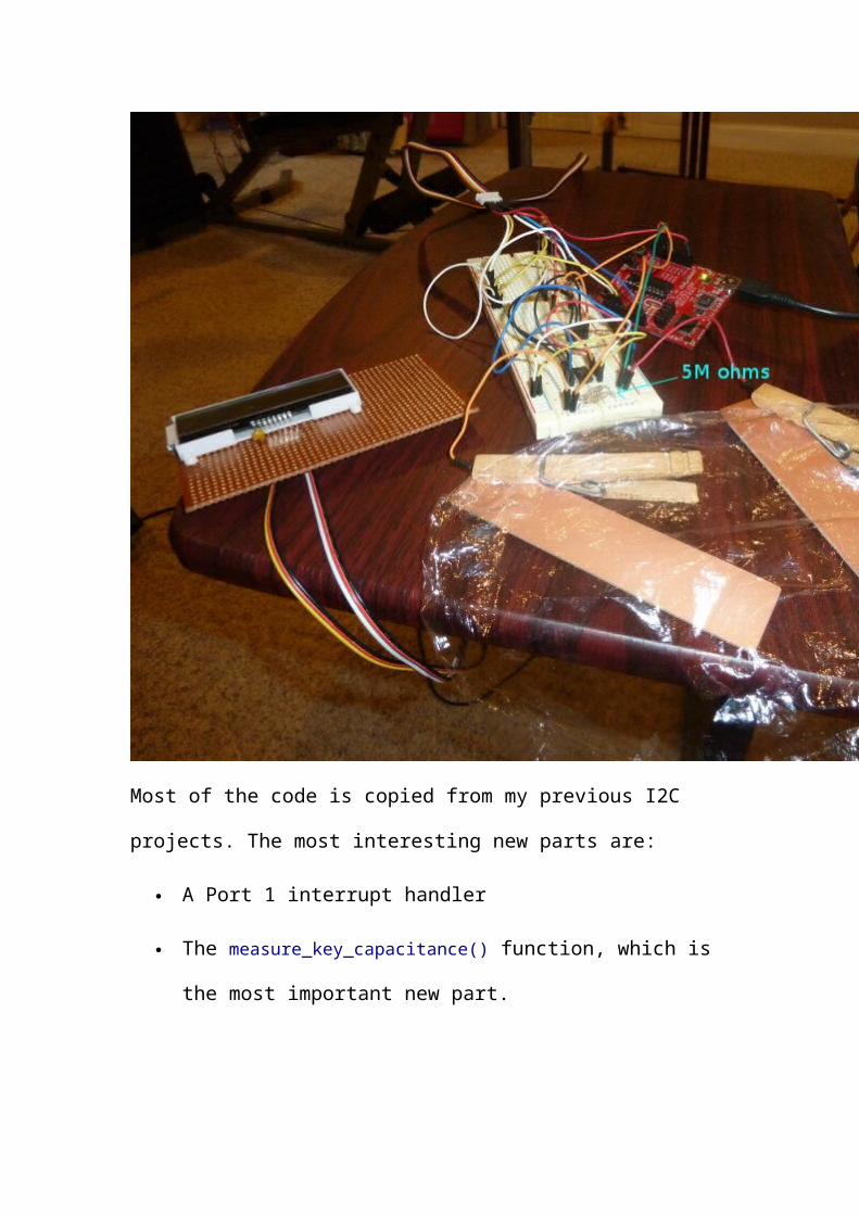
clear_key_light = 0; }
// Set interrupts on so Port 2 handler can trigger. __bis_SR_register( GIE );
// Turn each wire on in turn to trigger an interrupt on port 2. P1OUT |= KEY_BLACK; asm( "nop \n\t" "nop \n\t" "nop \n\t" ); P1OUT &= ~KEY_BLACK;
P1OUT |= KEY_WHITE; asm( "nop \n\t" "nop \n\t" "nop \n\t" ); P1OUT &= ~KEY_WHITE;
P1OUT |= KEY_GRAY; asm( "nop \n\t" "nop \n\t" "nop \n\t" ); P1OUT &= ~KEY_GRAY;
P1OUT |= KEY_VIOLET; asm( "nop \n\t" "nop \n\t" "nop \n\t" ); P1OUT &= ~KEY_VIOLET;
P1OUT |= KEY_ORANGE; asm( "nop \n\t" "nop \n\t" "nop \n\t" ); P1OUT &= ~KEY_ORANGE;
P1OUT |= KEY_BROWN; asm( "nop \n\t" "nop \n\t" "nop \n\t" ); P1OUT &= ~KEY_BROWN;
// Decrement the counts in key_pending[] and record any key releases. for( i = 0; i < NUM_KEYS; i++ ) { if( key_pending[i] ) key_pending[i]--; if( !key_pending[i] ) key_pressed[i] = 0; }
// Clear the watchdog timer interrupt flag. IFG1 &= ~WDTIFG;}
/* Port 2 interrupt service routine. Triggered by presses of * the keypad or by opening of the reed switch.
*/void Port_2 (void) __attribute__((interrupt(PORT2_VECTOR)));void Port_2(void) { int i; int mask = 0;
for( i = 0; i < NUM_KEYS; i++ ) { if( P2IFG & p2_color[i] ) { // Check if this color triggered the interrupt. mask |= p2_color[i];
if( P1OUT & p1_color[i] ) { // Check if the other color for this key is also on. if( key_pending[i] && !key_pressed[i] ) { key_pressed[i] = 1;
do_key( key_symbol[i] ); }
key_pending[i] = 2; // Remember for next time. } } } // Clear interrupt flag. P2IFG &= ~mask;
if( P2IFG & REED_SWITCH ) { P2IFG &= ~REED_SWITCH; }}
At this point, I don’t have a reed switch, though there is
code there that will eventually trigger on that. I also haven’t
made use of the piezo speaker in this code, though it
operates on Port 1 pins p1.6 and p1.7.
The key_pending[] array is how the code checks that a key
has triggered on two successive interrupts before
registering a key press (and how it checks that a key has
failed to trigger on two successive timer interrupts for a key
release). In Port_2() it is set to 2 each time a key triggers,
and in WDT_ISR() it is decremented.
This code was built with msp430-gcc version 4.5.3 and
installed:
$ msp430-gcc -O2 -mmcu=msp430g2452 -o keypad.elf keypad.c$ mspdebug rf2500 "prog keypad.elf"Last updated 2011-12-24 11:18:31 CST
本 内 容 来 自 如 下 网 站 : http://
dbindner.freeshell.org/msp430/