document tentang
DESCRIPTION
dokumenTRANSCRIPT

JM EPEG (2012) 21:1061-1069 DOI: 10.1007/s 11665-011-9956-6
© ASM International 1059-9495/$19.00
Environmentally Assisted Cracking of Drill Pipes in Deep Drilling Oil and Natural Gas Wells
M. Ziomek-Moroz
(Subm itted A pril 1, 2011)
Corrosion fatigue (CF), hydrogen induced cracking (HIC) and sulfide stress cracking (SSC), or environmentally assisted cracking (EAC) have been identified as the most challenging causes of catastrophic brittle fracture of drill pipes during drilling operations of deep oil and natural gas wells. Although corrosion rates can be low and tensile stresses during service can be below the material yield stress, a simultaneous action between the stress and corrosive environment can cause a sudden brittle failure of a drill component. Overall, EAC failure consists of two stages: incubation and propagation. Defects, such as pits, second-phase inclusions, etc., serve as preferential sites for the EAC failure during the incubation stage. Deep oil and gas well environments are rich in chlorides and dissolved hydrogen sulfide, which are extremely detrimental to steels used in drilling operations. This article discusses catastrophic brittle fracture mechanisms due to EAC of drill pipe materials, and the corrosion challenges that need to be overcome for drilling ultra-deep oil and natural gas wells.
Keywords deep drilling, environmentally assisted cracking, high strength low alloy steels, sour gas wells
1. Introduction
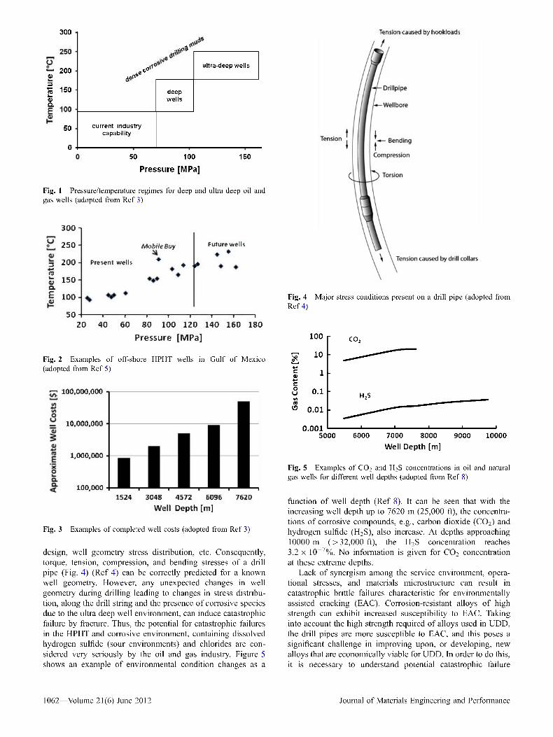
The United States’ predicted 60% growth in energy demand by 2030 makes oil and natural gas primary target fuels for energy generation (Ref 1). The fact that the peak of oil production from relatively shallow wells (i.e., less than 4572 m (15,000 ft)) is about to be reached is pushing the oil and natural gas industry into drilling deeper wells. The literature data indicate that there are an estimated 3.2 x 10¹² to 3.7 x 10¹² m3 (114-132 trillion cubic feet (TCP)) of technically recoverable natural gas resources onshore and another 1.6 x 10¹² m3 (55 TCP) of recoverable natural gas offshore trapped in reservoirs below 4572 m (15,000 feet) (Ref 2). In addition, deep wells are often very large producers of oil and natural gas relative to their shallow counterparts. However, producing oil and natural gas from these deep wells often means drilling in high-pressure and high-temperature (HPHT) conditions while using dense corrosive muds for which the oil and gas industry does not have full capabilities (Fig. 1) (Ref 3). Till date, the oil and natural gas industry has successfully drilled and completed HPHT wells in Mobile Bay, Thomasville, East Texas, and the New Gulf of Mexico Fields (Ref 4). However, it is expected that still deeper wells will be necessary to tap the available reserves with pressures and/or temperatures higher than those in the Mobile Bay well (Fig. 2) (Ref 5).
M. Ziomek-Moroz, National Energy Technology Laboratory, U.S. Department o f Energy, 1450 Queen Avenue SW, Albany, OR 97321. Contact e-mail: Margaret.Ziomek-Moroz@,NETL.DOE.GOV.
Drilling costs for wells deeper than 7620 m (25,000 ft), also called ultra-deep wells, are of a great concern to the oil and gas industry. The oil and natural gas industry bases the ultra-deep drilling (UDD) costs on drilling rates of penetration (ROP). Examples of cost estimates for completed conventional, deep and ultra-deep wells are shown in Fig. 3 (Ref 3). As shown in Fig. 3, the drilling costs increase exponentially with increasing well depths. It costs approximately $850,000 to drill and complete conventional wells, approximately 1524 m (5000 ft) deep, compared to $M50 to drill and complete UDD wells. Some reports applicable to deep drilling in the U.S. Gulf Coast indicate that approximately 50% of rig time is spent drilling the last 10% of the hole (Ref 6). Therefore, improving the rate of penetration in the deepest segments of deep well drilling through technological advancements is necessary. These cost estimates do not include unscheduled drilling downtime caused by catastrophic failures of drilling string components, casing, and completion equipment.
It is reported that a drill string failure happens, on average, one out of every seven drilling operations and costs more than $100,000 per failure event (Ref 7). A downhole failure of the drill string, resulting in complete drill pipe separation, also called twistoff, can be very expensive, especially if it is not possible to recover the remaining part of the drill string from the hole. In such instances, the operators may need to drill a new hole parallel to the section occupied by the broken drill string. The time for completing this unplanned operation, and replacing the broken equipment, may cost upward of one million dollars. Therefore, detecting the presence of holes formed in the drill strings before catastrophic failure will be advantageous for oil and gas drillers, reducing the cost of overall costs associated with drilling the well.
The perforation in the drill pipe, also, called washout, can be very difficult to detect, since it may form at high depths during the later stages of drilling operations and slight changes in pressure and flow rate data can be easily overlooked by the operator. A lot of effort is, therefore, placed on drill string
Journal of Materials Engineering and Performance Volume 21(6) June 2012— 1061
300
“ 2000)
1 150 i 5Q.
50
0
..vt<\4
5e c0<<aaO5
ultra-deep w ells
deepw ells
current industry capability
Tension caused by hookloads
50 100
Pressure [MPa]150
Fig. 1 Pressure/temperature regimes for deep and ultra deep oil and gas wells (adopted from R ef 3)
300 i
2 5 0 -
3 200 -| t?£ 150
f f H50
Present w ells
Mobile Bay
♦♦ >
Future w ells * ♦
20—,— 40
" i "
60— i------------1------------1------------1------------1------------1
80 100 120 140 160 180
Pressure [MPa]
Fig. 2 Examples o f off-shore HPHT wells in G ulf o f Mexico (adopted from R ef 5)
r r 1 0 0 ,0 0 0 ,0 0 0
_ 10,000,000
1,000,000
100,0001524 3048 4572 6096 7620
Well Depth [m]
Fig. 3 Examples o f completed well costs (adopted from R ef 3)
design, well geometry stress distribution, etc. Consequently, torque, tension, compression, and bending stresses of a drill pipe (Fig. 4) (Ref 4) can be correctly predicted for a known well geometry. However, any unexpected changes in well geometry during drilling leading to changes in stress distribution, along the drill string and the presence of corrosive species due to the ultra deep well environment, can induce catastrophic failure by fracture. Thus, the potential for catastrophic failures in the HPHT and corrosive environment, containing dissolved hydrogen sulfide (sour environments) and chlorides are considered very seriously by the oil and gas industry. Figure 5 shows an example of environmental condition changes as a
Drillpipe
Wellbore
Tension Bending
Compression
Torsion
\ \ Tension caused by drill collars
Fig. 4 Major stress conditions present on a drill pipe (adopted from R ef 4)
100
co>cU 0.1 (8^ 0.01
0.0015000 6000 7000 8000 9000 10000
Well Depth [m]
Fig. 5 Examples o f C 0 2 and H2S concentrations in oil and natural gas wells for different well depths (adopted from R ef 8 )
function of well depth (Ref 8). It can be seen that with the increasing well depth up to 7620 m (25,000 ft), the concentrations of corrosive compounds, e.g., carbon dioxide (C02) and hydrogen sulfide (H2S), also increase. At depths approaching 10000 m (>32,000 ft), the H2S concentration reaches 3.2 x 10 7%. No information is given for C 02 concentration at these extreme depths.
Lack of synergism among the service environment, operational stresses, and materials micro structure can result in catastrophic brittle failures characteristic for environmentally assisted cracking (EAC). Corrosion-resistant alloys of high strength can exhibit increased susceptibility to EAC. Taking into account the high strength required of alloys used in UDD, the drill pipes are more susceptible to EAC, and this poses a significant challenge in improving upon, or developing, new alloys that are economically viable for UDD. In order to do this, it is necessary to understand potential catastrophic failure
1062—Volume 21(6) June 2012 Journal of Materials Engineering and Performance

mechanisms caused by EAC in drill pipes. A lesson-learned approach should serve as a foundation for developing these new alloys that meet stringent requirements for the UDD operations in HPHT corrosive environments.
2. Stress Distributions in Drilling HPHT Wells
Chandler et al. (Ref 9) defined UDD as having a true vertical depth (TVD) greater than 7620 m (25,000 ft) with no more than a total horizontal departure (THD) from the vertical of less than 0.25. This type of drilling imposes a different stress state to the drill string compared with extended reach drilling (ERD), which uses large horizontal departures at shallower depths as shown schematically in Fig. 6. While ERD is considered to be primarily torque dependent, secondary concerns related to tensile stresses are also important. UDD, on the other hand, is primarily tension dependent with secondary concerns related to the torque imposed on the drill string (Ref 9). In a corrosive environment, where fatigue may be accelerated by corrosion, corrosion fatigue (CF) may present a unique challenge because of the higher mean stress during the fatigue cycle. Complicating the situation further is the use of the very high strength alloys for UDD conditions. The susceptibility to sulfide stress cracking (SSC) and/or hydrogen-induced cracking (HIC), while under high tension, is a real concern even when there is little or no fatigue cycling (Ref 10-12).
Material requirements for drill pipe are very stringent in most instances, but especially for UDD operations. As noted, drilling to greater depths generally requires increasing the strength-to-weight ratio of the drill pipe material. For steel drill pipe, this means increasing the yield strength. However,
,— , 14000 -I
£ 12000 -.cQ. 10000 -<ti
o 8000 -"roV 6000 -
1 4000 -<ti 2000 -
£ 0 -C
Primary Tension-Secondary Torque: Increased HIC/ or SSC Susceptibility
Ultra-deep Drilling Region
/
VerticalDrillingRegion
Extended Rich Drilling
TTHD/TVD>0.2S
Primary Torque- Secondary Tension: Increased CF Susceptibility
2000 4000 6000 8000 10000Total Horizontal Departure [m]
Fig. 6 Difference between vertical drilling and extended-reach drilling. Ultra-deep drilling region above 7620 m (25,000 ft) is also shown (adopted from R ef 9)
increasing the yield strength decreases toughness, and for drilling operations, in general, high fracture toughness is also important. Therefore, any steel used in UDD operations must be strong, tough, corrosion resistant, readily available, easily joined, and inexpensive (Ref 9, 13). Finally, drilling to the deeper depths in UDD wells exposes the drill string to elevated temperatures (typically greater than 200 °C, or a 2 x increase in temperature) and high pressures (typically >100 MPa, or about 3-4x increase in pressure) greater than those found in conventional drilling operations (Fig. 2) (Ref 2, 8).
3. Materials Requirements for Drill Pipes
Steels traditionally used for drill pipes are C-Mn or Cr-Mo type. Drill pipes, in accordance with the American Petroleum Institute (API) 5D specification, have to be seamless and heat treated either by quenching and tempering, or normalizing and tempering, to the required minimum strength. Also, the maximum amount of P or S allowed in the alloy is 0.03 wt.% for each element. Table 1 shows the mechanical properties and heat treatments for different steel grades to meet the required API 5D specification (Ref 14).
Chemical composition ranges for grade E are similar to plain carbon steel (AISI 1041 or 1045) modified with approximately 1.5 Mn and 0.25 Mo. As shown in Table 1, they are either normalized or normalized and tempered: Grades X, G, and S are 4100 series steels in modified (H) form; and Grades X and G have similar chemical composition ranges: 0.2-0.3% C, 1.2-1.5% Mn 0.4-0.6% Cr, and 0.2-0.5 Mo. However, Grade X is usually normalized and tempered, while Grade G is quenched and tempered. Grade S with the highest strength (Table 1) among the four API drill pipes is usually quenched and tempered. Its chemical composition range is 0.27-0.35% C, 1.5-1.6% Mn, 0.1-0.5% Cr, 0.3-0.4% Mo, and 0.012-0.016% V. Also, hardness increases with increasing yield strength of the drill pipes ranging from 20 to 28 Rc for Grade E, 27 to 30 Rc for Grade X, 30 to 34 Rc for Grade G, and 34 to 37 Rc for Grade S. The nominal chemical compositions of API steel drill pipes are summarized in Table 2 (Ref 14).
At present, API’s Grade S-135 is the industry standard for high strength, low alloy (HSLA) steel. However, drilling to depths greater than 4572 m (15,000 ft) requires increasing the strength-to-weight ratio of the drill pipes materials. The higher strength-to-weight ratio steels under development include Z-140, V-150, and UD-165 drill pipes (Ref 9, 13, 15). Grade Z-140 was specifically developed for use in extreme drilling conditions present in HPHT wells. Grade V-150 was developed for applications that require ultra-high strength steel.
Table 1 Mechanical properties and heat treatments for each grade of seamless steel drill pipes as required by API 5D specification (adopted from Ref 14)
Yield strength (MPa/ksi)
Minimum Charpy impact energy at 21 °C (J/ft-lbf)
Grade Maximum Minimum strength (MPa/ksi) 1 Sample 3 Sample average Heat treatment
E-75 725/105 517/75 689/100 Normalized or normalized & temperedX-95 862/125 655/95 724/105 47/35 54/40 Quenched & tempered or normalized & temperedG-105 931/135 724/105 793/115 47/35 54/40) Quenched & tempered or normalized & temperedS-135 1138/165 931/135 1000/145 47/35 54/40) Quenched & tempered or normalized & tempered
Journal of Materials Engineering and Performance Volume 21(6) June 2012— 1063

Grade UD-165 provides a 22% improvement in strength-to- weight ratio in comparison to S-135. It is worth noting that Z-140, V-150, and UD-165 are currently not covered by API standards.
For UDD applications, carbon fiber composites, aluminum, and titanium were considered as alternatives to HSLA steels. Each of these materials has some advantages and disadvantages over steel drill pipes. For example, the carbon fiber composite drill pipes are non-magnetic and have lower weight, higher strength-to-weight ratio, and excellent corrosion and fatigue resistance. However, their main disadvantage is their lower hydraulic performance and efficiency associated with pressure losses through the pipe. To have the necessary structural properties (torsional strength, tensile capacity, and pressure integrity), a composite drill pipe must be significantly thicker than the conventional steel drill pipe for the same drilling operation. Depending on the design parameters, the wall thickness of composite drill pipe may be up to twice the wall thickness of comparable conventional steel drill pipe. This results in a significantly reduced inner diameter of the pipe, resulting in unacceptable pressure losses throughout the pipe making it unsuitable for not only for UDD operations but also for extended-reach drilling (Ref 9).
Aluminum drill pipes have been successfully used by the petroleum industry for a long time. Typically, they are made of 2015-T6 aluminum alloy. Their advantages include lower weight, good fatigue, and corrosion resistance to general corrosion at neutral pH. However, there are many disadvantages that include susceptibility to pitting corrosion, severe dissolution at high and low pH values, susceptibility to CF in drilling fluids containing 18% NaCl, and SCC susceptibility in oxygen-containing brines (Ref 14). Also, aluminum yield strength is low (476 MPa) (69 ksi) compared to steel, for example, resulting in low strength-to-weight ratio compared to HSLA steels. Moreover, as temperature increases, yield strength decreases. Since temperatures above 180 °C are expected in ultra deep wells, this makes aluminum drill pipes unsuitable for these operations.
On the other hand, titanium-based drill pipes, for example, Ti-6A1-4V or Ti-3Al-8V-6Cr-4Mo-4Zr Grade 19 (Beta C) have several advantages over API steel drill pipes. These include lower weight, higher strength-to-weight ratio, good corrosion, and fatigue resistance. However, the main disadvantage in using titanium drill pipe is their cost relative to steel. With respect to UD-165 HSLA steel drill pipe, the typical titanium alloys have approximately 15% lower strength-to-weight ratio (Ref 9), and this makes them less attractive for UDD operations.
Table 2 Chemical composition of drill pipes meeting API 5D specification (adopted from Ref 14)
Grade Chemical composition (wt.%)
E-75 1041 or 1045 + 1.2Mn, 0.2Mo, P < 0.03, S < 0.03
X-95 0.2-0.3C, 1.2-1.5Mn, 0.4-0.6Cr, 0.2-0.6Mo, P < 0.03, S < 0.03, Fe-balance
G-105 0.2-0.3C, 1.2-1.5Mn, 0.4-0.6Cr, 0.2-0.6Mo, P < 0.03, S < 0.03, Fe-balance
S-135 0.27-0.35C, 1.5-1.6Mn, 0.1-0.5Cr, 0.3-0.4Mo, 0.012-0.016V, P < 0.03, S < 0.03, Fe-balance
The disadvantages associated with alternative materials for UDD operations indicate that the industry still needs to rely on the high-strength steels for drilling ultra-deep wells. In order to improve drill pipe reliability and make the drilling process cost effective, it is of the utmost importance limit, or to prevent completely, any catastrophic failures caused during UDD under HPHT conditions. CF, HIC and/or SSC have been recognized as typical forms of EAC that occur under these conditions and they are discussed in more detail in the next section.
4. Corrosion Fatigue
The literature data indicate that ~75% of all the drill string failures are caused by fatigue or fatigue-induced mechanical failure. There are two types of fatigue loading conditions experienced by drill strings during operation (Ref 16):
1. Rotating-bending when the drill string passes aroundbends. (1-3 Hz)
2. Vibrational fatigue loading including
(a) lateral vibration (rattling in the annular gap, 0.5-10s of Hz);
(b) tension-vibration (from drill bit stick and slip 0.05-0.5 Hz);
(c) axial vibration (impacting hard formation 1-10 Hz).
In general, if a material is stressed repeatedly above fatigue limit, it fails after a certain number of cycles.
Fatigue failures occurring in non-corrosive environments, such as dry air, inert gases, or vacuum, can be caused by extrusions and corresponding intrusions along the metal grains close to the surface due to slip band formation as a result of mechanical deformation. These slip bands result in notch formation and finally cracking. If the cyclic stress is below the fatigue limit, then, work hardening only occurs and failure does not occur (Ref 12).
In order to determine fatigue limits, tests are conducted by subjecting smooth and notched metal tensile samples to cyclic stresses of various magnitudes and plotted as cyclic stress vs. number of cycles to crack initiation or failure. These curves are known as S-N curves (Ref 10, 17).
Typical S-N curves for smooth and notched steel samples are shown in Fig. 7. As can be seen in the figure, the fatigue
Fatigue Limits forSmooth and Notched Steel Samples
Q.
(/)
1.0E+03 1.0E+04 1.0E+05 1.0E+06 1.0E+07 1.0E+08 1.0E+09Num ber of Cycles to Failure
Fig. 7 Schematic S-N curves o f smooth and notched o f steel in air (adopted from R ef 10, 17)
1064—Volume 21(6) June 2012 Journal of Materials Engineering and Performance

Fig. 8 Twistoff o f S-135 caused by pitting and fatigue (adopted from R ef 14)
limit is independent of stress at low stress levels. However, the notch presence affects substantially the fatigue limit of a material. The fatigue limit for the smooth sample is higher than that for the notched sample. The applied stress rises at the notch tip and exceeds the yield strength of the material causing a substantial reduction in fatigue strength. Also, the fatigue resistance is directly related to the radius or the sharpness of the notch. The sharper the notch or the smaller the notch radius is, the lower is the fatigue resistance.
Notch depth also affects fatigue resistance. Deeper notches substantially reduce fatigue resistance in comparison to shallow ones. Mechanical notches on the external drill pipe surfaces, made, for example, by tongs and/or rotary slips, can serve as initiation sites for brittle fatigue crack propagation leading to catastrophic drill pipe failure. If the fatigue crack propagates very rapidly in a transverse direction, then twistoff of a drill pipe may occur (Fig. 8) (Ref 14). However, if the fatigue crack propagates relatively slowly and the drilling medium erodes the affected material, then a hole or a washout forms in the drill pipe (Fig. 9) (Ref 18). Washouts usually occur in higher fracture toughness drill pipes, while twistoffs occur in lower fracture toughness drill pipes. Drill pipe twistoff requires labor- intensive and time-consuming fishing operations to trip the string in comparison to washouts. Thus, the API and ISO standards recommend minimum fracture toughness determined by the Charpy impact test for higher strength drill pipe grades to avoid twistoff occurrence (Ref 14).
The effect of corrosive environment on fatigue performance of steels can be significant. Figure 10 shows S-N curves generated for 0.18% C steel samples in the presence of aerated 3% NaCl (corrosive environment) and in deaerated water (inert environment) (Ref 19, 20). The results indicate that the presence of the NaCl solutions reduces significantly the fatigue performance of the material. Also, the results indicate that, in the NaCl solution, the S-N curve continues to decrease as the number of load cycles increases, indicating a lack of a definite fatigue limit. This phenomenon is widely observed for steels in
Fig. 9 Washout caused by pitting and corrosion fatigue in a drill pipe (adopted from R ef 18)
400 r
TuQ-1 , 350 ■<U"O
J 300 ■Q.
* 250 ■<u
10 2 0 0 i i ■ i i i i l l i ■ ■ ■ ■ ■ 111 p
1.00E+05 1.00E+06 1.00E+07
Num ber Cycles to Failure
Fig. 10 S-N curves o f 0.18% carbon steel in deaerated water and aerated 3% NaCl (adopted from R ef 19, 20)
corrosive environments indicating that brittle fracture can occur at very low stress levels, apparently because of a corrosive attack upon the extrusions and intrusions at slip bands created in the surface, preventing work hardening and strengthening of metal (Ref 12). This explains why CF damage is a synergistic action of corrosion and fatigue, and is greater than that caused by the sum of both acting separately (Ref 11). It also explains why corrosion resistance of a metal is more important than high tensile strength in establishing optimum resistance to CF.
Corrosion fatigue is most pronounced at low stress frequencies since a low-frequency cycle results in greater contact time between metal and corrosive solution (Ref 17). This indicates that life of the component is shorter because time available per cycle for corrosion action is also longer. CF occurs, therefore, in all alloys and pure metals and is not specific to certain corrosive environments. Sooner or later, however, in all environments, CF occurs and shows the same variation with different corrosive environments similar to general corrosion.
Dearated FLO
Aearated 3% NaCl
Journal of Materials Engineering and Performance Volume 21(6) June 2012— 1065

Table 3 Effect of dissolved gases in 5% NaCl on corrosion fatigue of carbon steel (adopted from Ref 21)
Dissolved gas in 5% NaCl
Endurance limit at 107
cycles (MPa/ksi)
Decrease from fatigue limit in
deaerated NaCl (%)
N 2 (deaerated) 207/30 0Air 69/10 67H2S 158/23 24H2S + air 103/15 50C 0 2 117/17 43C 0 2 + air 117/17 43C 0 2 + H2S 76/11 63
In particular, CF strength of all steels in NaCl is lower than that in, for example, fresh water. This can be explained by the process of pit initiation due to pitting corrosion and crack propagation. In chloride-containing environments, pits can initiate at inclusions, such as manganese sulfide particles, due to a local chemistry difference between the matrix and the inclusion. Corrosion pits subsequently act as stress risers and initiate cracks. Corrosion dissolution is high at the crack tip, and as a result the crack tip radius changes. Inside the crack, the environment can be acidic due to formation of HC1. Since the radius constantly decreases because of a simultaneous mechanical and corrosion action, CF strength can be quite low. Thus, pitting corrosion in steels and other metals and alloys is of great importance in CF crack initiation. Therefore, alloys with a high resistance to CF must also possess a high inherent resistance to pitting corrosion.
In addition, CF of carbon steel is influenced by the presence of dissolved gases in NaCl. Table 3 shows the highest reduction in CF performance for a drill pipe in aerated 5% NaCl in comparison to dissolved H2S. Carbon dioxide dissolved in deaerated or aerated 5% NaCl is equally detrimental to the steel. Dissolved H2S in NaCl containing C 02 further decreases the fatigue limit of the steel (Ref 21). The beneficial effect of solution deaeration on the steel fatigue behavior is shown in Fig. 11. The results show the presence of the fatigue limit in deaerated 5% NaCl and its absence in the aerated solution (Ref 21). This result was also confirmed by Duquette (Ref 19) for 3% NaCl. This indicates that dissolved oxygen plays a major role in the CF mechanism in neutral pH solutions (Ref 20, 21).
The mode of CF failure is usually transgranular without branching and the crack tip is blunt (Ref 10). The final stages of CF for drill pipes are similar to those occurring during fatigue. When a significant portion of the cross-sectional area is compromised the remaining portion is not strong enough to withstand the applied tensile stress and purely mechanical failure takes place (Ref 14).
Corrosion fatigue may be reduced by reducing the stress on the component. This can be accomplished by using a stress reliving heat treatment on the alloy or by shot-peening the surface to induce compressive stresses. Highly polished surfaces with no notches also improve resistance to CF. Low concentration of pitting agents (e.g., Cl- ) and oxygen, addition of corrosion inhibitors, and pH control (basic) will be very beneficial in reducing CF. For mild steel, deaeration of 3% NaCl restores the normal fatigue limit in air (Fig. 11). In general, coatings (plastic or sacrificial metal) can be helpful as well.
250
Q. 200
-o 150Aerated 5% NaCl
100
50
V )
1.0E+071.0E+06Number of Cycles to Failure
Fig. 11 Effect o f dissolved oxygen concentration in 5% NaCl at room temperature on fatigue behavior o f AISI-SAE 1035 steel (adopted from R ef 21)
5. Hydrogen-Induced Cracking and Sulfide Stress Cracking
In the presence of wet H2S, high-strength steels may crack very fast under a different failure mechanism, e.g., HIC/SSC. Hydrogen sulfide forms when calcium sulfate (CaS04) reacts with hydrocarbons, such as methane—CH4 (Eq 1), ethane— C2H6 (Eq 2), and propane—C3H8 (Eq 3) as shown in the following reactions (Ref 22):
CaS04 + CH4 -► H2S + CaC03 + H20 (Eq 1)
1.5CaS04 + C2H6 -► 1.5H2S + 1.5CaC03 + H20 + 0.5C
(Eq 2)
2CaS04 + C3H8 -► 2H2S + 2CaC03 + H20 + C (Eq 3)
and in the downhole conditions (Eq 4) (Ref 23):
4FeS2 + 4H20 + 6H+ -*■ 4Fe2+ + SO5 + 7H2S(aq) (Eq 4)
Therefore, sour gas environments are unavoidable duringdrilling operation in spite of the fact that corrosion inhibitors are continually added to the drilling fluids to “control” the detrimental action of H2S. Although H2S is not classified as a strong acid, it dissociates sufficiently to yield a minimum pH of ~4 in saturated solutions (Ref 24) according to the following reaction (Eq 5):
H2S = 2H+ + S2~ (Eq 5)
The S2_ anions act as a hydrogen poisons, i.e., they retard recombination of nascent hydrogen atoms on corroding metal surfaces or at the crack tip (Eq 6) obtained from reduction of H+ (Eq 7) or water (Eq 8):
Me —> Me2+ + 2e (anodic reaction) (Eq 6)
H+ + e —► H (cathodic reaction: acidic solutions) (Eq 7)
H20 + e —► H + OH- (cathodic reaction: neutral solutions)(Eq 8)
The S2- increases the residence time of nascent H, and enhances hydrogen penetration into the metal lattice. Thus, the hydrogen produced plays a crucial role in all modes of hydrogen damage, including HIC/hydrogen embrittlement,
1066—Volume 21(6) June 2012 Journal of Materials Engineering and Performance

hydrogen blistering, and hydrogen attack. The presence of hydrogen in the steel depends on the type of the steel, the microstructure, and inclusion, and the tensile stress distributions. This includes the effect of total pressure of the system and residual stress from working, cold-forming, or welding operations (Ref 25), which can subsequently cause embrittlement, and possibly cracking.
When atomic hydrogen diffuses into the metal but remains in solid solution in the crystal structure, it reduces the metal’s ductility and deformability, which is called hydrogen embrittlement. If internal cavities exist, then a catalytic process on the surface may lead to the formation of molecular hydrogen, causing high pressure and blister formation. If a metal is embrittled by hydrogen and is subjected to tensile stresses above a certain critical value, then HIC occurs. The higher the hydrogen content, the lower the critical stress required for the failure. If HIC is caused by the presence of hydrogen sulfide, then the term SSC is used.
The major environmental factors controlling SSC are H2S concentration, pH, and temperature. Other environmental factors that may increase susceptibility to SSC include solution composition, flow rates, changes in surface conditions by the presence of corrosion products or non-protective films on the corroding surfaces, and the presence of corrosion inhibitors that could be unstable or act as catalysts for hydrogen diffusion into metal.
In some cases SSC can be reversed if the hydrogen is removed by holding the sample at elevated temperatures for a certain period of time. Figure 12 shows fracture times as a function of applied stresses of uncharged and hydrogen precharged AISI-SAE 4340 steel samples that were held at 150 °C for 0.5 and 12 h, respectively, before testing. For the uncharged sample, fracture time does not increase significantly with decreasing applied stresses. However, for the hydrogen precharged, and subsequently thermally treated samples, the samples time to fracture, also called an incubation time, decreases with increasing applied stresses until it reaches a minimum stress (a plateau) below which failure due to SSC will not occur. The incubation time and minimum stress for HIC increase with increasing baking time. This indicates that a relatively low-temperature baking operation allows some dissolved hydrogen to escape from the alloy. If all hydrogen escaped, the original properties of the alloy would be restored. However, hydrogen damage effects from further hydrogen charging cannot be restored by removal of dissolved hydrogen
(Ref 26). The benefit of higher temperature can be used for components that operate continuously above 65 °C. However, that would not apply to components that are cooled below 65 °C during operation (Ref 25).
Since many operations occur at room temperature, the industry has adopted a pH-pH2S diagram, known as NACE/ ISO SSC diagram, for “quantifying” the overall aggressiveness of the environment, Fig. 13 (Ref 25, 27). It is worth noting that the diagram was established for the oil country tubular good (OCTGs) for those material grades up to PI 10. Other higher strength steels and/or welded products can follow a similar trend but the precise location of region boundaries can be different from those noted in Fig. 13, and the boundaries for these newer alloys need to be established.
From Fig. 13, Region 1 (low-sour region) represents a mild environment, e.g., SSC is not expected to occur in steels up to strength PI 10 even though metallurgical requirements are not met. Region 2 (transition region) is a zone within which some judgment has to be used regarding metallurgical requirements. Region 3 (high-sour region) represents the most aggressive environment, and the one that is the most detrimental to a material’s SSC resistance. Steels used in this region must meet all the metallurgical requirements, which include strength limit, uniform hardness distribution across the wall within 10% of the maximum value, and homogeneous microstructure (Ref 25). Although materials are being evaluated according to the accepted industry standards, and recommendations for heat- treatment and hardness requirements are specified, and methods of controlling service environments are met, brittle failures due to SSC accelerated crack propagation can still take place. The cracks detected in the material susceptible to HIC/SSC may be transgranular or intergranular with minor branching. Figure 14 shows crack propagation in S-135 after sour service (Ref 28). It is worth pointing out, that SSC and CF do not involve the anodic mechanism of embrittlement required of SCC (Ref 10).
Taking into account that the H2S species are always present in drilling fluids, the corrosiveness of drilling fluids must be controlled by using corrosion inhibitors. H2S is neutralized by adding alkaline agents, or H2S scavengers, to the drilling fluids (muds). Water-based drilling fluids with p H ~ 11 were used in drilling 4777 m (16,000 ft) wells using X-95 (minimum yield strength 655 MPa (95,000 psi) (Ref 29). For drilling 6096 m (20,000 ft) wells, the oil-based drilling fluid containing calcium hydroxide was used with a similar material, e.g., X-95 (Ref 30). Also, the addition of S2- scavengers, such as copper carbonate,
2500no H2 pre-charging
2000
“8 1500
5 - 1000
500
o 1-0.1 10 1000 100000
Time to Failure [min]
Fig. 12 Fracture o f AISI-SAE 4340 steel after thermal removal o f H 2 at 150 °C for 0.5 and 12 h (adopted from R ef 26)
xQ.0)%o
76.5
65.5
54.5
43.5
30.01
- Non-sour . Region
Low-sour Region 1
- ^ ^ n ran sitionRegion 2 / ^ High-sour Region 3
« ■ > ■ ■ ....................... ............. » « » »»0.1 1 10
H2S Amount [ %]
100
Fig. 13 Regions o f environmental severity with respect to sulfide stress cracking o f HSLA steels in 5% NaCl, 0.5% CH 3 COOH, 0.4% CH 3 COONa, and xh,s; pH adjustment: HC1 or NaOH (adopted from R ef 25, 27)
Journal of Materials Engineering and Performance Volume 21(6) June 2012— 1067

Fig. 14 Crack propagation in S-135 drill pipe after sour service (adopted from R ef 28)
or zinc carbonate, to drilling fluid prevented brittle failures while drilling 4777 m (20,000 ft) deep wells. However, corrosion inhibitors are not a “catch all” solution for UDD of the well (Ref 31); indeed, cracking that is characteristic of hydrogen embrittlement has been noticed in S-135 drill pipe as shown in Fig. 14.
In general, the embrittling effect of hydrogen is prevalent in iron-based alloys and steels because of the restricted slip capabilities in the predominant body centered cubic (BCC) structure (Ref 10). However, face-centered cubic (FCC) stainless steels and FCC alloys of aluminum, nickel, and copper are more resistant to HIC/SSC because of inherent high ductility and lower diffusivity for hydrogen, but their susceptibility can increase if highly cold worked (Ref 32). Reactive alloys of titanium, zirconium, vanadium, niobium, and tantalum can be embrittled by insoluble or soluble hydrides (Ref 10). All the effects of the conditions described above must be considered when developing a new class of HPHT materials resistant to fatigue, CF, HIC, and SSC for UDD applications.
6. Summary
Corrosion fatigue, hydrogen embrittlement, and stress corrosion cracking have been identified as the major catastrophic failure modes of high-strength steel drill strings. Differentiating these forms of corrosion from one another may be difficult, and therefore, perfonning laboratory tests in the conditions that simulated service environments are required to have a better understanding of the potential for each type of failure mode. New high-strength materials can then be developed with superior resistance to CF, HIC, and/or SSC.
References
1. S.A. Holditch and R.R. Chianelli, Factors that will Influence Oil and Gas Supply in 21st Century, MRS Bull., 2008, 33, p 317-323
2. B. Tomer, Consortium Adds New Dimension to Research Efforts, GasTIPS, 2007, 13, p 10-13
3. MIT-led Interdisciplinary Panel “The Future of Geothermal Energy: Impact o f Enhanced Geothermal Systems (EGS) on the United States,”
http://geothermal.inel.gov/publications/future_of_geothermal_energy.pdf
4. B. Craig, Materials for Deep Oil and Gas Well Construction. Adv. Mater. Process. May, 2008, p 33-35
5. C. Williams, “Possible SOO Regulations HT/HP Equipment,” MMS Workshop, January 23, 2008 (New Orleans, LA)
6 . 2007 Annual Plan for the Ultra-deepwater and Unconventional Natural Gas and Other Petroleum Resources Research and Development Program, DOE/NETL-2007/1294
7. Changent Systems “Drill String Failure, Cases and Prevention,” http ://www. changent.ispeedway. com/
8 . R. Zeringue, HPHT Completion Challenges, SPE High Pressure/High Temperature Sour Well Design Applied Technology Workshop, May 17-19, 2005 (The Woodlands, TX), SPE 97589
9. B. Chandler, M J. Jellison, M.L. Payne, and J.S. Shepard, Advances and Emerging Drillstring Technologies Overcome Operational Challenges, World Oil, 2006, 10, p 23-34
10. D.A. Jones, Principles and Prevention o f Corrosion, 1st ed., Macmillan Publishing Company, New York, 1991, p 234-287
11. H.H. Uhlig and R.W. Revie, Corrosion and Corrosion Control, 3rd ed., John Wiley & Sons, New York, 1985, p 123-157
12. G. Wranglen, An Introduction to Corrosion and Protection o f Metals, Chapman and Hall, London, 1985, p 105-115
13. G. Brown, D. Belczewski, J. Mostoway, and M.J. Jellison, Game Changing Drilling Tubular Technologies, CADE/CAODC Drilling Conference, Calgary, Alberta, Canada, 2003
14. B. Craig, Oilfield Metallurgy and Corrosion, 3rd ed., Metcorr, Denver, 2004, p 84-115
15. M.L. Payne, R. B. Chandler, M.J. Jellison, and J. Shepard, World Oil, July (2003): OTC 15327
16. K.A. Macdonald and J.V. Bjune, Failure Analysis o f Drillstrings, Eng. Fail. Anal., 2007, 14, p 1641-1666
17. M.G. Fontana, Corrosion Engineering, McGraw-Hill Publishing Company, New York, 1986, p 109-152
18. S. Lu, Y. Feng, F. Luo, C. Qin, and X. Wang, Failure Analysis of IEU Drill Pipe Wash Out, Int. J. Fatigue, 2005, 27, p 1360-1365
19. D J. Duquette and H.H. Uhlig, Effect o f Dissolved Oxygen and NaCl on Corrosion Fatigue o f 0.18% Carbon Steel, Trans. Am. Soc. M et, 1968, 61, p 449^156
20. D J. Duquette, A Review of Aqueous Corrosion Fatigue, Corrosion Fatigue: Chemistry, Mechanics and Microstructure, NACE-2 ed., O. Deveraux, A J. McEvily, and R.W. Steahle, Eds., June 14-18, 1971 (Storrs, CT), National Association o f Corrosion Engineers, 1986, p 12-24
21. P. Mehdizadeh, R.L. McGlosson, and J.E. Landers, Corrosion Fatigue Performance of a Carbon Steel in Brine Containing Air, H2S and C 0 2, Corrosion, 1966, 22, p 325-335
22. C. Yue, S. Li, K. Ding, and N. Zhong, Thermodynamics and Kinetics o f Reactions Between C 1-C3 Hydrocarbons and Calcium Sulfate in Deep Carbonate Reservoirs, Geochem. J., 2006, 40, p 87-94
23. H. Ohmoto and M.B. Goldhaber, Fixation o f Seawater Sulfate as Sulfide in Ore Deposits, Geochemistry o f Hydrothermal Ore Deposits, 3rd ed., L. Bames, Ed., John Wiley and Sons Publishers, New York, 1997,p 552-578
24. P.W. Atkins, Physical Chemistry, 4th ed., W. H. Freeman and Company, New York, 1990, p 225-231
25. “Guidelines on Materials Requirements for Carbon and Low Alloy Steels for H2 S-Containing Environments in Oil and Gas Production,” Number 16, European Federation of Corrosion Publications, p 13-19
26. A.R. Troiano, The Role o f Hydrogen and Other Interstitials on the Mechanical Behavior of Metals, Trans. Am. Soc. M et, 1960,52, p 54-80
27. “ Petroleum and Natural gas Industries-Materials for Use in H2 S- containing Environments in Oil and Gas Production, Part 2: Cracking- resistant Carbon and Low Alloy Steels, and the Use o f Cast Irons,” NACE, MR0175/ISO15156, National Association of Corrosion Engineers, 2003, p 1-12
28. G.L. Garwood, “Material Selection for Downhole and Surface Equipment for Sour Gas Condensate Wells,” NACE CORROSION/ 73: Paper No. 73053
29. G.E. Uthlaut, Jay Field Developed Fast Despite Unique Problems, Oil Gas J., 1972, 70, p 66-71
30. W.L. Kirk, Deep Drilling Practices in Mississippi, J. Petrol. Technol, 1972, 24,p 633-642
1068—Volume 21(6) June 2012 Journal of Materials Engineering and Performance
31. R.S. Treseder, Oil Industry Experience with Hydrogen Embrittlement and Stress Corrosion Cracking, Stress Corrosion Cracking and Hydrogen Embrittlement o f Iron Base Alloys, NACE-5 ed., R.W. Staehle, J. Hochmann, R.D. McCright, and J.E. Slater, Eds., June
12-16, 1973 (Unieux-Finniny), National Association of Corrosion Engineers, 1977, p 147-161
32. B. Craig, Hydrogen Damage, Corrosion, J.R. Davis and J.D. Destefani, Eds., ASM International, (13), 1987, p 163-171
Journal o f Materials Engineering and Performance Volume 21(6) June 2012— 1069