documentation kl9020, kl9050 - directory contents … of contents kl9020, kl9050 version: 2.0.03...
TRANSCRIPT

Documentation
KL9020, KL9050
K-Bus Extension
2.0.02017-09-29
Version:Date:


Table of contents
KL9020, KL9050 3Version: 2.0.0
Table of contents1 Foreword .................................................................................................................................................... 5
1.1 Notes on the documentation........................................................................................................... 51.2 Safety instructions .......................................................................................................................... 61.3 Documentation Issue Status........................................................................................................... 7
2 Product Overview ...................................................................................................................................... 82.1 Functional description..................................................................................................................... 82.2 KL9020: End Terminal with RJ45 socket........................................................................................ 92.3 KL9050: Coupler Terminal............................................................................................................ 102.4 Technical Data.............................................................................................................................. 11
3 Fitting and wiring..................................................................................................................................... 123.1 Instructions for ESD protection ..................................................................................................... 123.2 Structure of a K-bus extension ..................................................................................................... 123.3 Installation on mounting rails ........................................................................................................ 153.4 Connection.................................................................................................................................... 17
3.4.1 Connection system........................................................................................................... 173.4.2 Wiring............................................................................................................................... 19
3.5 Power supply ................................................................................................................................ 203.6 ATEX - Special conditions (standard temperature range) ............................................................ 223.7 ATEX Documentation ................................................................................................................... 23
4 Diagnostics .............................................................................................................................................. 244.1 Diagnostic LEDs ........................................................................................................................... 244.2 Fault table for K-Bus interruption .................................................................................................. 26
5 Appendix .................................................................................................................................................. 275.1 Ordering information ..................................................................................................................... 275.2 Support and Service ..................................................................................................................... 28

Table of contents
KL9020, KL90504 Version: 2.0.0

Foreword
KL9020, KL9050 5Version: 2.0.0
1 Foreword
1.1 Notes on the documentation
Intended audience
This description is only intended for the use of trained specialists in control and automation engineering whoare familiar with the applicable national standards.It is essential that the documentation and the following notes and explanations are followed when installingand commissioning these components.It is the duty of the technical personnel to use the documentation published at the respective time of eachinstallation and commissioning.
The responsible staff must ensure that the application or use of the products described satisfy all therequirements for safety, including all the relevant laws, regulations, guidelines and standards.
Disclaimer
The documentation has been prepared with care. The products described are, however, constantly underdevelopment.
We reserve the right to revise and change the documentation at any time and without prior announcement.
No claims for the modification of products that have already been supplied may be made on the basis of thedata, diagrams and descriptions in this documentation.
Trademarks
Beckhoff®, TwinCAT®, EtherCAT®, Safety over EtherCAT®, TwinSAFE®, XFC® and XTS® are registeredtrademarks of and licensed by Beckhoff Automation GmbH.Other designations used in this publication may be trademarks whose use by third parties for their ownpurposes could violate the rights of the owners.
Patent Pending
The EtherCAT Technology is covered, including but not limited to the following patent applications andpatents: EP1590927, EP1789857, DE102004044764, DE102007017835 with corresponding applications orregistrations in various other countries.
The TwinCAT Technology is covered, including but not limited to the following patent applications andpatents: EP0851348, US6167425 with corresponding applications or registrations in various other countries.
EtherCAT® is registered trademark and patented technology, licensed by Beckhoff Automation GmbH,Germany
Copyright
© Beckhoff Automation GmbH & Co. KG, Germany.The reproduction, distribution and utilization of this document as well as the communication of its contents toothers without express authorization are prohibited.Offenders will be held liable for the payment of damages. All rights reserved in the event of the grant of apatent, utility model or design.

Foreword
KL9020, KL90506 Version: 2.0.0
1.2 Safety instructions
Safety regulations
Please note the following safety instructions and explanations!Product-specific safety instructions can be found on following pages or in the areas mounting, wiring,commissioning etc.
Exclusion of liability
All the components are supplied in particular hardware and software configurations appropriate for theapplication. Modifications to hardware or software configurations other than those described in thedocumentation are not permitted, and nullify the liability of Beckhoff Automation GmbH & Co. KG.
Personnel qualification
This description is only intended for trained specialists in control, automation and drive engineering who arefamiliar with the applicable national standards.
Description of symbols
In this documentation the following symbols are used with an accompanying safety instruction or note. Thesafety instructions must be read carefully and followed without fail!
DANGER
Serious risk of injury!Failure to follow the safety instructions associated with this symbol directly endangers thelife and health of persons.
WARNING
Risk of injury!Failure to follow the safety instructions associated with this symbol endangers the life andhealth of persons.
CAUTION
Personal injuries!Failure to follow the safety instructions associated with this symbol can lead to injuries topersons.
Attention
Damage to the environment or devicesFailure to follow the instructions associated with this symbol can lead to damage to the en-vironment or equipment.
Note
Tip or pointerThis symbol indicates information that contributes to better understanding.

Foreword
KL9020, KL9050 7Version: 2.0.0
1.3 Documentation Issue StatusVersion Comment2.0.0 • Migration
• Update Technical data• Chapter Notes on ESD protection added• Update chapter Connection added• Chapters ATEX - special conditions (standard temperature range) and
ATEX documentation added• Firmware and hardware versions updated• Structure update
1.2.0 • Description of the structure of a K-bus extension expanded• Mounting description expanded
1.1.1 • Foreword and appendix updated• Product overview for KL9050 updated
1.1 • Ordering information updated• Description of the diagnostic LEDs corrected
1.0 First release
Firmware and hardware versions
DocumentationVersion
KL9020 KL9050Firmware Hardware Firmware Hardware
2.0.0 03 12 01 061.2.0 03 08 01 031.1.1 03 07 01 021.1 01 02 01 011.0 01 02 01 01
The firmware and hardware versions (delivery state) can be found in the serial number printed on the side ofthe terminal.
Syntax of the serial number
Structure of the serial number: KK YY FF HH
KK - week of production (CW, calendar week)YY - year of productionFF - firmware versionHH - hardware version
Example with ser. No.: 35 05 03 07:
35 - week of production 3505 - year of production 200503 - firmware version 0307 - hardware version 07
Product Overview
KL9020, KL90508 Version: 2.0.0
2 Product Overview
2.1 Functional description
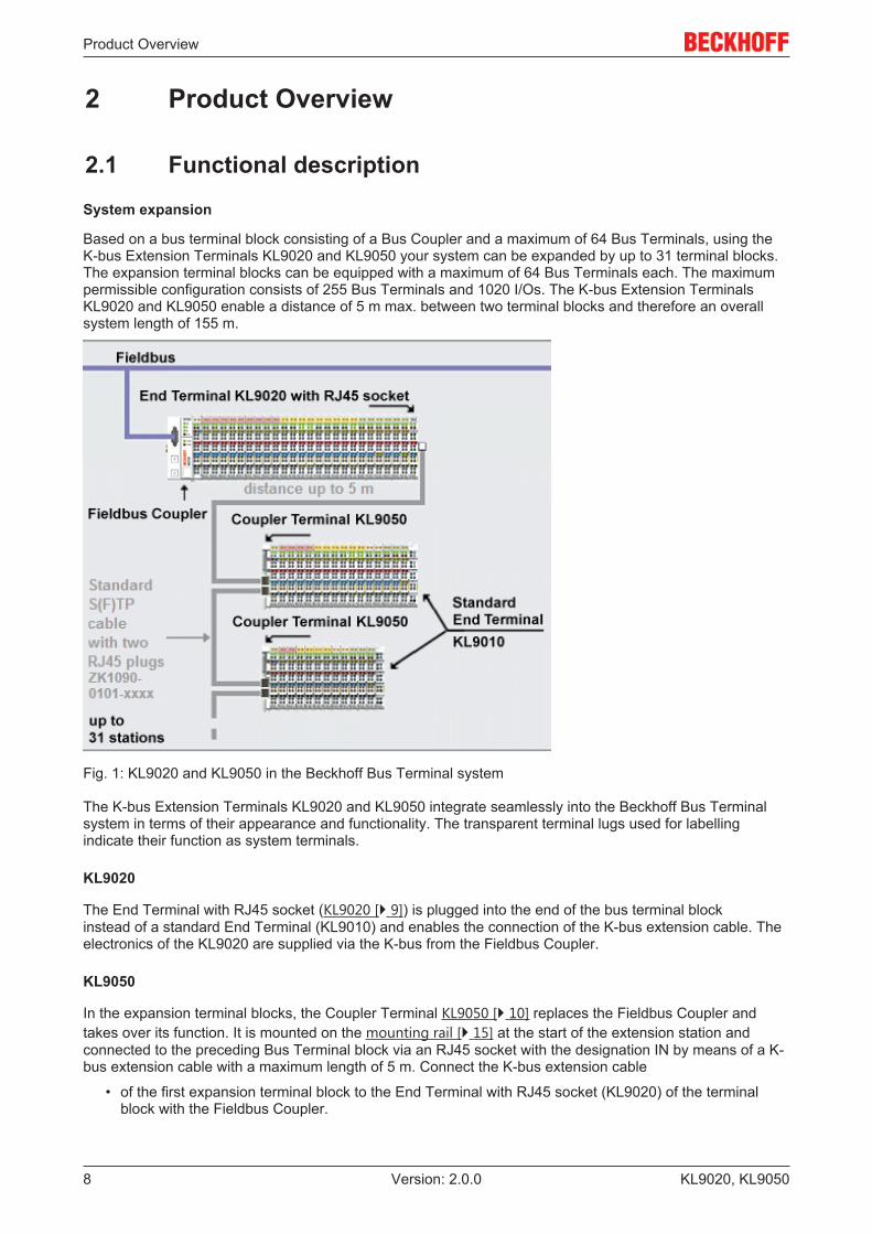
System expansion
Based on a bus terminal block consisting of a Bus Coupler and a maximum of 64 Bus Terminals, using theK-bus Extension Terminals KL9020 and KL9050 your system can be expanded by up to 31 terminal blocks.The expansion terminal blocks can be equipped with a maximum of 64 Bus Terminals each. The maximumpermissible configuration consists of 255 Bus Terminals and 1020 I/Os. The K-bus Extension TerminalsKL9020 and KL9050 enable a distance of 5 m max. between two terminal blocks and therefore an overallsystem length of 155 m.
Fig. 1: KL9020 and KL9050 in the Beckhoff Bus Terminal system
The K-bus Extension Terminals KL9020 and KL9050 integrate seamlessly into the Beckhoff Bus Terminalsystem in terms of their appearance and functionality. The transparent terminal lugs used for labellingindicate their function as system terminals.
KL9020
The End Terminal with RJ45 socket (KL9020 [} 9]) is plugged into the end of the bus terminal blockinstead of a standard End Terminal (KL9010) and enables the connection of the K-bus extension cable. Theelectronics of the KL9020 are supplied via the K-bus from the Fieldbus Coupler.
KL9050
In the expansion terminal blocks, the Coupler Terminal KL9050 [} 10] replaces the Fieldbus Coupler andtakes over its function. It is mounted on the mounting rail [} 15] at the start of the extension station andconnected to the preceding Bus Terminal block via an RJ45 socket with the designation IN by means of a K-bus extension cable with a maximum length of 5 m. Connect the K-bus extension cable
• of the first expansion terminal block to the End Terminal with RJ45 socket (KL9020) of the terminalblock with the Fieldbus Coupler.

Product Overview
KL9020, KL9050 9Version: 2.0.0
• of all other expansion terminal blocks with the RJ45 socket (identified with OUT) of the CouplerTerminal (KL9050) of the preceding expansion terminal block.
The power contacts and the corresponding connection points of the Coupler Terminal are electrically isolatedfrom the K-bus.
K-bus extension cable
The data is transmitted between the terminal blocks via eight-core Ethernet cables with RJ45 plugs. Beckhoffoffers pre-assembled cables in different lengths, which can be customized with commercially availableEthernet tools.
Note
The K-bus Extension Terminals should also work with cables from other manufacturers.However, Beckhoff recommends the use of Beckhoff Ethernet cables [} 27], which aretested for the specified functionality.
2.2 KL9020: End Terminal with RJ45 socket
Fig. 2: KL9020
Interface FunctionK-Bus extension output RJ45 socket for the continuing K-bus extension

Product Overview
KL9020, KL905010 Version: 2.0.0
2.3 KL9050: Coupler Terminal
Fig. 3: KL9050
LED No. FunctionPower Vk, green A LED indicates whether the supply voltage for the electronics of the Coupler Terminal is switched on.Power, green C LED indicates whether the supply voltage for the I/O terminals of the terminal block is switched on. The
power supply of the terminals is via the power contacts.RUN (K-Bus IN), green - LED indicates that data is being transmitted on the K-bus.ERR (K-Bus IN), red - LED indicating a fault on the K-Bus.
Terminal point No. FunctionVk 24 V 1 Input of the +24 V supply voltage for the Coupler Terminal electronics+24 V 2 Input of the +24 V supply voltage for the power contacts (internally connected to terminal point 6)0 V 3 Input of the 0 V supply voltage for the power contacts (internally connected to terminal point 7)PE 4 PE connection (internally connected to terminal point 8)Vk 0 V 5 Input of the 0 V supply voltage for the Coupler Terminal electronics+24 V 6 Input of the +24 V supply voltage for the power contacts (internally connected to terminal point 2)0 V 7 Input of the 0 V supply voltage for the power contacts (internally connected to terminal point 3)PE 8 PE connection (internally connected to terminal point 4)
Interface FunctionK-bus In RJ45 socket for the incoming K-bus extensionK-bus OUT RJ45 socket for the continuing K-bus extensionK-bus Internal K-bus of the Bus Terminal blockPower Contacts Internal power contacts of a bus terminal block
Function Switch [} 14] Switch for the termination resistor of the Coupler Terminal

Product Overview
KL9020, KL9050 11Version: 2.0.0
2.4 Technical DataTechnical Data GeneralNumber of Bus Terminals per Fieldbus Coupler with BKxx20 or BKxx50 fieldbus coupler: max. 255
with Fieldbus Couplers BKxx00 or BKxx10: max. 64Number of bytes per Fieldbus Coupler limited by Fieldbus Coupler and Fieldbus Limit (see documentation for the Field-
bus Coupler being used)Increase in runtime due to K-bus extension negligible (see runtime calculation in the documentation for the Fieldbus Coupler
used)Length of cable between 2 terminal blocks max. 5 mTotal length of cable (from KL9020 to the lastKL9050)
max. 155 m (31 x 5 m)
Topology Bus structure
Technical Data KL9020 [} 9] End Terminal with RJ45 socket for K-Bus extensionFieldbus independentNumber of KL9020 per Fieldbus Coupler 1Configuration automaticCurrent consumption from the K-bus typically 70 mADielectric strength 500 V (shielding, base plate / K-bus)Permissible ambient temperature range during oper-ation
0 °C ... + 55 °C
Permissible ambient temperature range during stor-age
-25 °C ... + 85 °C
Permissible relative air humidity 95 %, no condensationVibration / shock resistance conforms to EN 60068-2-6 / EN 60068-2-27EMC immunity / emission conforms to EN 61000-6-2 / EN 61000-6-4Weight approx. 45 gDimensions (W x H x D) approx. 26 mm x 100 mm x 70 mm
Mounting [} 13] on 35 mm mounting rail conforms to EN 60715
Installation position variableProtection class IP20Approvals CE, UL, ATEX [} 22], GL see Beckhoff Homepage
Technical Data KL9050 [} 10] K-Bus Extension Coupler TerminalNumber of Bus Terminals per KL9050 max. 64Number of KL9050 per Fieldbus Coupler max. 31Configuration via switch Function switch [} 14]Supply voltage 24 VDC (-15%/+20%)Current consumption (via Terminals Vk 24V, Vk 0V) maximum 200 mA
Calculation: 70 mA + (K-bus current of the terminal block) / 4Starting current 2.5 x nominal currentK-bus power supply (for Bus Terminals) maximum 400 mAPower contacts voltage maximum 30 VDC
Power contact current load 10 A max. (short-circuit 125 A)Dielectric strength 500 V (power contact/supply voltage/fieldbus)Permissible ambient temperature range during oper-ation
0 °C ... + 55 °C
Permissible ambient temperature range during stor-age
-25 °C ... + 85 °C
Permissible relative air humidity 95 %, no condensationVibration / shock resistance conforms to EN 60068-2-6 / EN 60068-2-27EMC immunity / emission conforms to EN 61000-6-2 / EN 61000-6-4Weight approx. 75 gDimensions (W x H x D) approx. 24.5 mm x 100 mm x 70 mm
Mounting [} 13] on 35 mm mounting rail conforms to EN 60715
Installation position variableProtection class IP20Approvals CE, UL, ATEX [} 22], GL see Beckhoff Homepage

Fitting and wiring
KL9020, KL905012 Version: 2.0.0
3 Fitting and wiring
3.1 Instructions for ESD protection
Attention
Destruction of the devices by electrostatic discharge possible!The devices contain components at risk from electrostatic discharge caused by improperhandling.ü Please ensure you are electrostatically discharged and avoid touching the contacts of
the device directly.a) Avoid contact with highly insulating materials (synthetic fibers, plastic film etc.).b) Surroundings (working place, packaging and personnel) should by grounded probably,
when handling with the devices.
c) Each assembly must be terminated at the right hand end with an EL9011 bus end cap,to ensure the protection class and ESD protection.
Fig. 4: Spring contacts of the Beckhoff I/O components
3.2 Structure of a K-bus extension
DANGER
Risk of injury through electric shock and damage to the device!Bring the Bus Terminals system into a safe, de-energized state before starting mounting,disassembly or wiring of the Bus Terminals!

Fitting and wiring
KL9020, KL9050 13Version: 2.0.0
Fig. 5: KL9020 and KL9050 in the Beckhoff Bus Terminal system
Mounting
When mounting, observe the information in the chapter entitled Mounting rail installation [} 15].
1. Ensure that the system is powered down and in a safe state.2. Install the first bus terminal block, consisting of the fieldbus coupler and the desired Bus Terminals, on
a mounting rail.Instead of a standard End Terminal (KL9010), install an End Terminal with RJ45 socket (KL9020) asthe last terminal at the end of the first Bus Terminal block.
3. Install the first expansion terminal block, consisting of a Coupler Terminal (KL9050) and the desiredBus Terminals, on a mounting rail [} 11].Install a standard End Terminal (KL9010) as the last terminal at the end of the first expansion terminalblock.
4. Connect one RJ45 plug of an Ethernet cable into the RJ45 socket of the KL9020 of the first bus termi-nal block until it clicks into place.Connect the other RJ45 plug of the Ethernet cable into the RJ45 socket (labelled IN) of the expansionterminal block Coupler Terminal (KL9050) until it clicks into place.
5. Install the next expansion terminal block, consisting of a Coupler Terminal (KL9050) and the desiredBus Terminals, on a mounting rail [} 11].Install a standard End Terminal (KL9010) as the last terminal at the end of this expansion terminalblock.
6. Connect one RJ45 plug of an Ethernet cable into the RJ45 socket (labelled OUT) of the KL9020 of theprevious expansion terminal block until it clicks into place.Connect the other RJ45 plug of the Ethernet cable into the RJ45 socket (labelled IN) of the KL9050 ofthe added expansion terminal block until it clicks into place.
7. Repeat steps 5 and 6 in order to connect further expansion terminal blocks. A maximum of 31 expan-sion terminal blocks can be connected.
8. Set the Function Switch [} 14] on all Coupler Terminals (KL9050) correctly.

Fitting and wiring
KL9020, KL905014 Version: 2.0.0
Function Switch
Fig. 6: KL9050 - Function Switch
• Switch position Next:The Function Switch of all Coupler Terminals (KL9050) to which a continuing Ethernet cable isconnected must be set to position Next!
• Switch position Last:Activate the terminating resistor at the last expansion terminal block of your K-bus extension system byswitching the Function Switch on the last Coupler Terminal (KL9050) to the Last position.
CAUTION
Danger to persons, the environment and equipmentü Correct setting of the Function Switches of all Coupler Terminals (KL9050) within a K-
bus extension system must be ensured!ü Correct setting of the Function Switches must also be ensured if Coupler Terminals
(KL9050) are replaced!ü Please note that all extension terminal blocks connected after a Coupler Terminal
(KL9050), whose Function Switch is set to the Last position, are not included correctlyin the process image! This means:
a) The inputs of these terminals are not visible in the process image!b) The outputs of these terminals are not controlled by the process image!ð The Function Switch may be set to the Last position only at the last Coupler Terminal
(KL9050) of the K-bus extension system!
Notes on the topology
Note
Notes on the connection of the KL9020 and KL9050 terminalsThe end terminal with RJ45 socket (KL9020) may only be used at the end of Bus Terminalblocks that are opened by a fieldbus coupler! All extension terminal blocks must be termi-nated by a KL9010 standard end terminal!At least one terminal with process image must be connected to each KL9050 Coupler Ter-minal! The operation of an extension terminal block with only one KL9010 (with no inputs oroutputs) is not permissible
Disassembly
When mounting, observe the information in the chapter entitled Mounting rail installation [} 15].
1. Ensure that the system is powered down and in a safe state.2. Press the plastic lock of the RJ45 plug and pull it from the socket.3. Carefully pull the orange-colored lug approximately 1 cm out of the terminal to be disassembled, until
it protrudes loosely. The lock with the C mounting rail is now released for this terminal, and the termi-nal can be pulled from the mounting rail without excessive force.
4. Grasp the released terminal with thumb and index finger simultaneous at the upper and lower groovedhousing surfaces and pull the terminal away from the mounting rail.

Fitting and wiring
KL9020, KL9050 15Version: 2.0.0
3.3 Installation on mounting rails
WARNING
Risk of electric shock and damage of device!Bring the bus terminal system into a safe, powered down state before starting installation,disassembly or wiring of the Bus Terminals!
Assembly
Fig. 7: Attaching on mounting rail
The Bus Coupler and Bus Terminals are attached to commercially available 35 mm mounting rails (DIN railsaccording to EN 60715) by applying slight pressure:
1. First attach the Fieldbus Coupler to the mounting rail.2. The Bus Terminals are now attached on the right-hand side of the Fieldbus Coupler. Join the compo-
nents with tongue and groove and push the terminals against the mounting rail, until the lock clicksonto the mounting rail.If the Terminals are clipped onto the mounting rail first and then pushed together without tongue andgroove, the connection will not be operational! When correctly assembled, no significant gap shouldbe visible between the housings.
Note
Fixing of mounting railsThe locking mechanism of the terminals and couplers extends to the profile of the mountingrail. At the installation, the locking mechanism of the components must not come into con-flict with the fixing bolts of the mounting rail. To mount the mounting rails with a height of7.5 mm under the terminals and couplers, you should use flat mounting connections (e.g.countersunk screws or blind rivets).
Fitting and wiring
KL9020, KL905016 Version: 2.0.0
Disassembly
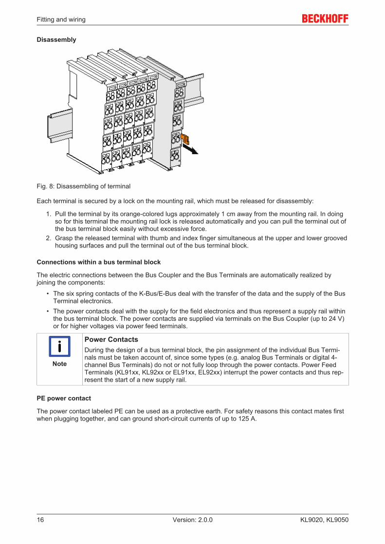
Fig. 8: Disassembling of terminal
Each terminal is secured by a lock on the mounting rail, which must be released for disassembly:
1. Pull the terminal by its orange-colored lugs approximately 1 cm away from the mounting rail. In doingso for this terminal the mounting rail lock is released automatically and you can pull the terminal out ofthe bus terminal block easily without excessive force.
2. Grasp the released terminal with thumb and index finger simultaneous at the upper and lower groovedhousing surfaces and pull the terminal out of the bus terminal block.
Connections within a bus terminal block
The electric connections between the Bus Coupler and the Bus Terminals are automatically realized byjoining the components:
• The six spring contacts of the K-Bus/E-Bus deal with the transfer of the data and the supply of the BusTerminal electronics.
• The power contacts deal with the supply for the field electronics and thus represent a supply rail withinthe bus terminal block. The power contacts are supplied via terminals on the Bus Coupler (up to 24 V)or for higher voltages via power feed terminals.
Note
Power ContactsDuring the design of a bus terminal block, the pin assignment of the individual Bus Termi-nals must be taken account of, since some types (e.g. analog Bus Terminals or digital 4-channel Bus Terminals) do not or not fully loop through the power contacts. Power FeedTerminals (KL91xx, KL92xx or EL91xx, EL92xx) interrupt the power contacts and thus rep-resent the start of a new supply rail.
PE power contact
The power contact labeled PE can be used as a protective earth. For safety reasons this contact mates firstwhen plugging together, and can ground short-circuit currents of up to 125 A.

Fitting and wiring
KL9020, KL9050 17Version: 2.0.0
Fig. 9: Power contact on left side
Attention
Possible damage of the deviceNote that, for reasons of electromagnetic compatibility, the PE contacts are capacitativelycoupled to the mounting rail. This may lead to incorrect results during insulation testing orto damage on the terminal (e.g. disruptive discharge to the PE line during insulation testingof a consumer with a nominal voltage of 230 V). For insulation testing, disconnect the PEsupply line at the Bus Coupler or the Power Feed Terminal! In order to decouple furtherfeed points for testing, these Power Feed Terminals can be released and pulled at least10 mm from the group of terminals.
WARNING
Risk of electric shock!The PE power contact must not be used for other potentials!
3.4 Connection
3.4.1 Connection system
WARNING
Risk of electric shock and damage of device!Bring the bus terminal system into a safe, powered down state before starting installation,disassembly or wiring of the Bus Terminals!
Overview
The Bus Terminal system offers different connection options for optimum adaptation to the respectiveapplication:
• The terminals of ELxxxx and KLxxxx series with standard wiring include electronics and connectionlevel in a single enclosure.
• The terminals of ESxxxx and KSxxxx series feature a pluggable connection level and enable steadywiring while replacing.
• The High Density Terminals (HD Terminals) include electronics and connection level in a singleenclosure and have advanced packaging density.

Fitting and wiring
KL9020, KL905018 Version: 2.0.0
Standard wiring (ELxxxx / KLxxxx)
Fig. 10: Standard wiring
The terminals of ELxxxx and KLxxxx series have been tried and tested for years.They feature integrated screwless spring force technology for fast and simple assembly.
Pluggable wiring (ESxxxx / KSxxxx)
Fig. 11: Pluggable wiring
The terminals of ESxxxx and KSxxxx series feature a pluggable connection level.The assembly and wiring procedure for the KS series is the same as for the ELxxxx and KLxxxx series.The KS/ES series terminals enable the complete wiring to be removed as a plug connector from the top ofthe housing for servicing.The lower section can be removed from the terminal block by pulling the unlocking tab. Insert the new component and plug in the connector with the wiring. This reduces the installation time andeliminates the risk of wires being mixed up.
The familiar dimensions of the terminal only had to be changed slightly. The new connector adds about 3mm. The maximum height of the terminal remains unchanged.
A tab for strain relief of the cable simplifies assembly in many applications and prevents tangling of individualconnection wires when the connector is removed.
Conductor cross sections between 0.08 mm2 and 2.5 mm2 can continue to be used with the proven springforce technology.
The overview and nomenclature of the product names for ESxxxx and KSxxxx series has been retained asknown from ELxxxx and KLxxxx series.
High Density Terminals (HD Terminals)
Fig. 12: High Density Terminals
The Bus Terminals from these series with 16 terminal points are distinguished by a particularly compactdesign, as the packaging density is twice as large as that of the standard 12 mm Bus Terminals. Massiveconductors and conductors with a wire end sleeve can be inserted directly into the spring loaded terminalpoint without tools.
Fitting and wiring
KL9020, KL9050 19Version: 2.0.0
Note
Wiring HD TerminalsThe High Density (HD) Terminals of the ELx8xx and KLx8xx series doesn't support plug-gable wiring.
Ultrasonically "bonded" (ultrasonically welded) conductors
Note
Ultrasonically “bonded" conductorsIt is also possible to connect the Standard and High Density Terminals with ultrasonically"bonded" (ultrasonically welded) conductors. In this case, please note the tables concern-ing the wire-size width below!
3.4.2 Wiring
WARNING
Risk of electric shock and damage of device!Bring the bus terminal system into a safe, powered down state before starting installation,disassembly or wiring of the Bus Terminals!
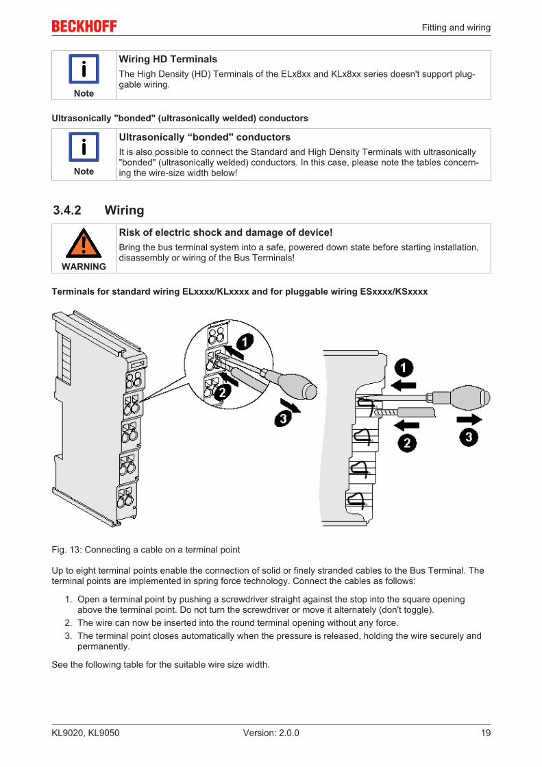
Terminals for standard wiring ELxxxx/KLxxxx and for pluggable wiring ESxxxx/KSxxxx
Fig. 13: Connecting a cable on a terminal point
Up to eight terminal points enable the connection of solid or finely stranded cables to the Bus Terminal. Theterminal points are implemented in spring force technology. Connect the cables as follows:
1. Open a terminal point by pushing a screwdriver straight against the stop into the square openingabove the terminal point. Do not turn the screwdriver or move it alternately (don't toggle).
2. The wire can now be inserted into the round terminal opening without any force.3. The terminal point closes automatically when the pressure is released, holding the wire securely and
permanently.
See the following table for the suitable wire size width.

Fitting and wiring
KL9020, KL905020 Version: 2.0.0
Terminal housing ELxxxx, KLxxxx ESxxxx, KSxxxxWire size width (single core wires) 0.08 ... 2.5 mm2 0.08 ... 2.5 mm2
Wire size width (fine-wire conductors) 0.08 ... 2.5 mm2 0,08 ... 2.5 mm2
Wire size width (conductors with a wire end sleeve) 0.14 ... 1.5 mm2 0.14 ... 1.5 mm2
Wire stripping length 8 ... 9 mm 9 ... 10 mm
High Density Terminals (HD Terminals [} 18]) with 16 terminal points
The conductors of the HD Terminals are connected without tools for single-wire conductors using the directplug-in technique, i.e. after stripping the wire is simply plugged into the terminal point. The cables arereleased, as usual, using the contact release with the aid of a screwdriver. See the following table for thesuitable wire size width.
Terminal housing High Density HousingWire size width (single core wires) 0.08 ... 1.5 mm2
Wire size width (fine-wire conductors) 0.25 ... 1.5 mm2
Wire size width (conductors with a wire end sleeve) 0.14 ... 0.75 mm2
Wire size width (ultrasonically “bonded" conductors) only 1.5 mm2
Wire stripping length 8 ... 9 mm
3.5 Power supply
DANGER
Danger for persons, the environment or equipmentBring the Bus Terminals system into a safe, de-energized state before starting mounting,disassembly or wiring of the Bus Terminals!
The supply connections Vk for the module electronics (K-bus) and supply connections for the field devices(power contacts) of a terminal block are galvanically separated from each other and can be supplied viaseparate 24 VDC voltage sources. If no electrical isolation is required between K-bus and field devices, themodule electronics and the field devices can be supplied from a single voltage source.
Attention
Notes on fail-safe operationFor the trouble-free operation of a K-bus extension system, the ground connection of the K-Bus power supplies (Vk 0V) of all terminal blocks must be connected with each other via alow-resistance connection (see Figure). This also includes the ground connection of the K-bus power supply of the higher-level Fieldbus Coupler!

Fitting and wiring
KL9020, KL9050 21Version: 2.0.0
Fig. 14: KL9020, KL9050 – Connection of the power supply

Fitting and wiring
KL9020, KL905022 Version: 2.0.0
3.6 ATEX - Special conditions (standard temperaturerange)
WARNING
Observe the special conditions for the intended use of Beckhoff fieldbuscomponents with standard temperature range in potentially explosive areas(directive 94/9/EU)!
• The certified components are to be installed in a suitable housing that guarantees aprotection class of at least IP54 in accordance with EN 60529! The environmental con-ditions during use are thereby to be taken into account!
• If the temperatures during rated operation are higher than 70°C at the feed-in points ofcables, lines or pipes, or higher than 80°C at the wire branching points, then cablesmust be selected whose temperature data correspond to the actual measured tempera-ture values!
• Observe the permissible ambient temperature range of 0 to 55°C for the use of Beck-hoff fieldbus components standard temperature range in potentially explosive areas!
• Measures must be taken to protect against the rated operating voltage being exceededby more than 40% due to short-term interference voltages!
• The individual terminals may only be unplugged or removed from the Bus Terminal sys-tem if the supply voltage has been switched off or if a non-explosive atmosphere is en-sured!
• The connections of the certified components may only be connected or disconnected ifthe supply voltage has been switched off or if a non-explosive atmosphere is ensured!
• The fuses of the KL92xx/EL92xx power feed terminals may only be exchanged if thesupply voltage has been switched off or if a non-explosive atmosphere is ensured!
• Address selectors and ID switches may only be adjusted if the supply voltage has beenswitched off or if a non-explosive atmosphere is ensured!
Standards
The fundamental health and safety requirements are fulfilled by compliance with the following standards:
• EN 60079-0:2012+A11:2013• EN 60079-15:2010
Marking
The Beckhoff fieldbus components with standard temperature range certified for potentially explosive areasbear one of the following markings:
II 3G KEMA 10ATEX0075 X Ex nA IIC T4 Gc Ta: 0 … 55°C
or
II 3G KEMA 10ATEX0075 X Ex nC IIC T4 Gc Ta: 0 … 55°C

Fitting and wiring
KL9020, KL9050 23Version: 2.0.0
3.7 ATEX Documentation
Note
Notes about operation of the Beckhoff terminal systems in potentially explo-sive areas (ATEX)Pay also attention to the continuative documentation
Notes about operation of the Beckhoff terminal systems in potentially explosive areas(ATEX)
that is available in the download area of the Beckhoff homepage http:\\www.beckhoff.com!
Diagnostics
KL9020, KL905024 Version: 2.0.0
4 Diagnostics
4.1 Diagnostic LEDs
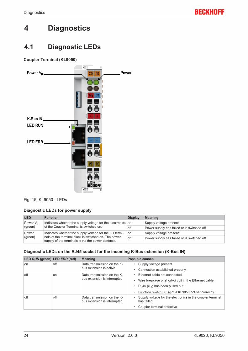
Coupler Terminal (KL9050)
Fig. 15: KL9050 - LEDs
Diagnostic LEDs for power supplyLED Function Display MeaningPower Vk(green)
Indicates whether the supply voltage for the electronicsof the Coupler Terminal is switched on.
on Supply voltage presentoff Power supply has failed or is switched off
Power(green)
Indicates whether the supply voltage for the I/O termi-nals of the terminal block is switched on. The powersupply of the terminals is via the power contacts.
on Supply voltage presentoff Power supply has failed or is switched off
Diagnostic LEDs on the RJ45 socket for the incoming K-Bus extension (K-Bus IN)LED RUN (green) LED ERR (red) Meaning Possible causeson off Data transmission on the K-
bus extension is active• Supply voltage present
• Connection established properlyoff on Data transmission on the K-
bus extension is interrupted• Ethernet cable not connected
• Wire breakage or short-circuit in the Ethernet cable
• RJ45 plug has been pulled out
• Function Switch [} 14] of a KL9050 not set correctlyoff off Data transmission on the K-
bus extension is interrupted• Supply voltage for the electronics in the coupler terminal
has failed
• Coupler terminal defective

Diagnostics
KL9020, KL9050 25Version: 2.0.0
End Terminal with RJ45 socket (KL9020)
The End Terminal KL9020 has no separate diagnostic LEDs. For diagnosing the K-bus of your bus terminalblock, the diagnostic LEDs I/O RUN and I/O ERR of the Fieldbus Coupler installed there are used.
Typical diagnostic LEDs of a Fieldbus CouplerLED I/O RUN(green)
LED I/O ERR(red)
Meaning Possible causes
on off Data transmission on the K-bus is active
• Supply voltage present
• Connection established properlyoff flashes Data transmission on the K-
bus is interrupted• Bus Terminal not plugged in properly
• Configuration error
• A mounted Bus Terminal is defectiveoff off Data transmission on the K-
bus is interrupted• Supply voltage for the electronics in the Fieldbus Coupler
has failed
• Fieldbus Coupler defective
Behavior in case of an error
If the communication between two or several bus terminal blocks of a K-bus extension system is interrupted
• the green RUN LEDs go out on the RJ45 sockets for the incoming K-bus extension (K-bus IN) on allKL9050s,
• the red ERR LEDs light up on the RJ45 sockets for the incoming K-bus extension (K-bus IN) on allKL9050s,
• the green LED I/O RUN of your Fieldbus Coupler will go out;• the red LED I/O ERR of the higher-level Fieldbus Coupler will flash rapidly, indicating an interruption of
the communication.
Flashing Code
If you now perform a reset for the Fieldbus Coupler, the Fieldbus Coupler searches for the cause of the faultand indicates it as a flashing code via the LED I/O ERR.
A flashing code is made up as follows:
• rapid flicker• short break• LED flashes m times for error code m• short break• LED flashes n times for error argument n• short break
Count the error code and the error argument. The flashing code is repeated continuously.
The error code for a K-bus interruption is 4. The error argument indicates the Bus Terminal after whichcommunication was interrupted. Examples are shown in the Fault table for K-bus interruption [} 26].

Diagnostics
KL9020, KL905026 Version: 2.0.0
4.2 Fault table for K-Bus interruption
Examples of fault indications in the event of communication interruption on the K-bus
Error Display Specific display
Possible cause
Remedy
no datatransmission onthe K-bus and K-bus extension
LED ERR of theCoupler TerminalsKL9050 are on
LED I/O ERR ofthe higher-levelFieldbus Couplerflashes rapidly
K-bus or K-busextension wasinterrupted
After any interruption of thedata transmission on the K-bus, the higher-levelFieldbus Coupler requires areset in order to restart thedata transmission or tolocate the fault.
LED ERR of theCoupler TerminalsKL9050 are on
I/O ERR LED ofthe higher-levelFieldbus Couplerflashes afterswitching on insuccession(flashing code[} 25]):
• fast• 4 times
slowly
• n [} 25]times slow
The Ethernet cableof a K-busextension is notplugged incorrectly
Fault after the n-th BusTerminal: ensure that theRJ45 plug is connectedcorrectly.
The FunctionSwitch of the lastCoupler Terminalis not in positionLast
Set the Function Switch[} 14] to Last!
Wrong Ethernetcable
Fault after the n-th BusTerminal: Do not use acrossed Ethernet cable forK-Bus extension!
LED Power Vk ofthe affectedCoupler Terminalis not on
Supply voltage ofa coupler terminalhas failed
Check the supply voltagesof the bus terminal blockafter the n-th Bus Terminal
LED ERR of theCoupler TerminalsKL9050 are on
LED I/O ERR ofthe higher-levelFieldbus Couplerflashes rapidly
Ethernet cable toolong
The length of the Ethernetcable between two terminalblocks must not exceed5 m.The overall length of the K-bus extension must notexceed 155 m (31 x 5 m).
Ethernet cabledefective
Check the Ethernet cable.
Wrong EndTerminal installed:The End Terminalwith RJ45 socket(KL9020) is onlyused at the busterminal block withthe FieldbusCoupler.
All extension terminal blocksmust be terminated with thestandard end terminal(KL9010)! See Notes on thetopology [} 14] of the K-busextension.
Please see the documentation of your Fieldbus Coupler for further error codes (m¹4) and the associatederror arguments.

Appendix
KL9020, KL9050 27Version: 2.0.0
5 Appendix
5.1 Ordering informationOrder identifier DescriptionKL9020 End Terminal with RJ45 socket [} 9] for K-bus extensionKL9050 K-bus Extension Coupler Terminal [} 10]ZK1090-0101-1005 K-bus extension cable with two plugs attached,
double shielded, grey, 50 cmZK1090-0101-1010 K-bus extension cable with two plugs attached,
double shielded, grey, 100 cmZK1090-0101-1020 K-bus extension cable with two plugs attached,
double shielded, grey, 200 cmZK1090-0101-1030 K-bus extension cable with two plugs attached,
double shielded, grey, 300 cmZK1090-0101-1050 K-bus extension cable with two plugs attached,
double shielded, grey, 500 cmZK1090-0000-1000 K-bus extension cable without plug,
double shielded, grey, goods sold in ringsZS1090-0001-0000 Modular RJ45 plug with anti-kink envelope, grey

Appendix
KL9020, KL905028 Version: 2.0.0
5.2 Support and ServiceBeckhoff and their partners around the world offer comprehensive support and service, making available fastand competent assistance with all questions related to Beckhoff products and system solutions.
Beckhoff's branch offices and representatives
Please contact your Beckhoff branch office or representative for local support and service on Beckhoffproducts!
The addresses of Beckhoff's branch offices and representatives round the world can be found on her internetpages:http://www.beckhoff.com
You will also find further documentation for Beckhoff components there.
Beckhoff Headquarters
Beckhoff Automation GmbH & Co. KG
Huelshorstweg 2033415 VerlGermany
Phone: +49(0)5246/963-0Fax: +49(0)5246/963-198e-mail: [email protected]
Beckhoff Support
Support offers you comprehensive technical assistance, helping you not only with the application ofindividual Beckhoff products, but also with other, wide-ranging services:
• support• design, programming and commissioning of complex automation systems• and extensive training program for Beckhoff system components
Hotline: +49(0)5246/963-157Fax: +49(0)5246/963-9157e-mail: [email protected]
Beckhoff Service
The Beckhoff Service Center supports you in all matters of after-sales service:
• on-site service• repair service• spare parts service• hotline service
Hotline: +49(0)5246/963-460Fax: +49(0)5246/963-479e-mail: [email protected]

List of illustrations
KL9020, KL9050 29Version: 2.0.0
List of illustrationsFig. 1 KL9020 and KL9050 in the Beckhoff Bus Terminal system......................................................... 8Fig. 2 KL9020 ........................................................................................................................................ 9Fig. 3 KL9050 ........................................................................................................................................ 10Fig. 4 Spring contacts of the Beckhoff I/O components......................................................................... 12Fig. 5 KL9020 and KL9050 in the Beckhoff Bus Terminal system......................................................... 13Fig. 6 KL9050 - Function Switch............................................................................................................ 14Fig. 7 Attaching on mounting rail ........................................................................................................... 15Fig. 8 Disassembling of terminal............................................................................................................ 16Fig. 9 Power contact on left side............................................................................................................ 17Fig. 10 Standard wiring............................................................................................................................ 18Fig. 11 Pluggable wiring .......................................................................................................................... 18Fig. 12 High Density Terminals................................................................................................................ 18Fig. 13 Connecting a cable on a terminal point ....................................................................................... 19Fig. 14 KL9020, KL9050 – Connection of the power supply.................................................................... 21Fig. 15 KL9050 - LEDs ............................................................................................................................ 24