xar format specificationsite.xara.com/support/docs/webformat/spec/xarformat... · web viewa down c...
TRANSCRIPT

Xar Format Specification
An open standard file format for vector graphics on the Web.
Abstract
The Xar file format, previously known as the Flare file format, is an ultra-compact, open, vector graphic format. It is also the native graphics format for Xara X application (and also its predecessors such as CorelXARA).
This document describes the format in detail and provides information for third parties interested in converting to or from this graphics format.
Why another vector graphics format? The Xar file format is not new. It dates back nearly ten years and so it predates more recent formats such as SVG. It is not designed to compete with SVG, but Xar files are considerably simpler to understand (the SVG spec is 700 pages) and more compact (often one tenth the size). However the primary reason for the existence of the open file format specification is to enable third parties to read and write the Xara X native files.
Background
The Xar vector graphic structure is that of modern vector programs, based on the Adobe Postscript rendering model, but with additional features. The graphic primitives are broadly similar to those available in Postscript, PDF and SVG. However Xara X, and thus the .xar file format, support more advanced graphic primitives and effects, for example a greater range of graduated fill types, graduated transparency, feathered vector shapes (soft edges), soft shadows and more. These enable the talented artist to create highly realistic and more ‘painterly’ effects with Xara X than is possible with traditional vector graphics solutions. See http://www.xara.com/gallery/
The format is designed so that rendering can be started before the entire file is available. The format is extendible, with a degree of forwards and backwards compatibility (this means older version of the software can still read files produced by newer version of the authoring software – they simply ignore the objects or parts they do not understand).
Part of the reason for this compactness is that Xar files are binary, rather than plain text as is SVG (which is XML). But with the recent movement towards a binary XML format, in
- 1 -

order to overcome the verbose nature of XML (and SVG), it seems things might come full circle. On the other hand Xara X offers a plain text variant of the .xar file (file extension .wix) which can help in understanding the structure of .xar files.
Status of this Document
This format was previously known as the Flare format but is now called Xar format. This document has been updated to describe the format as implemented by versions of XaraX up to and including Xara Xtreme 3.0.
Change log
This log lists all updates made to this specification from 1 November 2004.
Date Change Description
2nd November 2004(Gerry Iles)
Added Change Log page
Updated definition of MATRIX structure and transformation functions in description of Transformed Path records
4th November 2004(Gerry Iles)
Removed broken links from TAG_VARIABLEWIDTHFUNC, TAG_STROKEDEFINITION and TAG_STROKEAIRBRUSH in Appendix A and labelled them as not currently used.
3rd December 2004(Gerry Iles)
Clarified description of path verb values.Added download link for XarLib library.
11th January 2005(Gerry Iles)
Moved download link for XarLib library.Added download link for XPFilter archive.Updated the guidelines for implementors.
13th January 2005(Gerry Iles)
New XaraX import/export filters page.Moved link to XPFilter archive.
25th February 2005 Added detailed description of transparency types.
- 2 -

(Gerry Iles)
30th June 2005(Gerry Iles)
Corrected values for line cap and line join attributes.Corrected order of coordinates in all bitmap and fractal fill and transparency attributes.Added note about inversion of alpha in 32 bpp RGBA PNGs.
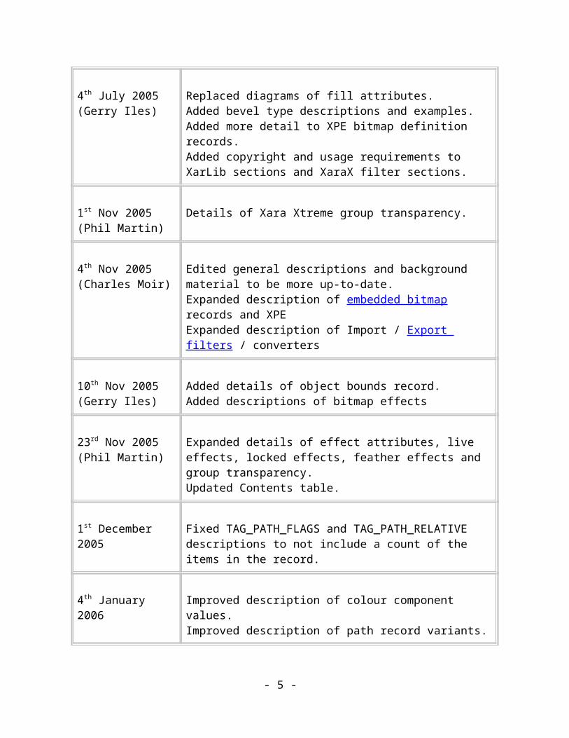
4th July 2005(Gerry Iles)
Replaced diagrams of fill attributes.Added bevel type descriptions and examples.Added more detail to XPE bitmap definition records.Added copyright and usage requirements to XarLib sections and XaraX filter sections.
1st Nov 2005(Phil Martin)
Details of Xara Xtreme group transparency.
4th Nov 2005(Charles Moir)
Edited general descriptions and background material to be more up-to-date.Expanded description of embedded bitmap records and XPEExpanded description of Import / Export filters / converters
10th Nov 2005(Gerry Iles)
Added details of object bounds record.Added descriptions of bitmap effects
23rd Nov 2005(Phil Martin)
Expanded details of effect attributes, live effects, locked effects, feather effects and group transparency.Updated Contents table.
1st December 2005 Fixed TAG_PATH_FLAGS and TAG_PATH_RELATIVE descriptions to not include a count of the items in the record.
4th January 2006 Improved description of colour component values.Improved description of path record variants.
13th June 2006 Removed Plugin Filter specific information.
- 3 -

(Gerry Iles)
24th July 2006Added details of documents containing multiple spreads TAG_CURRENTATTRIBUTES_PHASE2, TAG_SPREAD_PHASE2 and TAG_PRINTERSETTINGS_PHASE2.
Added notes about attribute optimisation in Xara programs.
Added details of TAG_SPREAD_FLASHPROPS
2nd August 2006 Modified note concerning use of path record variants.
2nd August 2006 Added details of TAG_DOCUMENTINFORMATION record.
8th August 2006 Changed names of bitmap object records from TAG_(CONTONE)BITMAP_OBJECT to TAG_NODE_(CONTONED)BITMAP to match source code.
10th August 2006 Corrected bitmap definition records to use Unicode string for bitmap name.
4th September 2006 Corrected values for winding rule attribute.
19th October 2006 Corrected descriptions of simple ellipse and rectangle records.
9th January 2007Added details of new records:TAG_DEFINEBITMAP_PNG_REALTAG_CLIPVIEW_PATHTAG_TEXT_STRING_POSTAG_TEXT_LINESPACE_LEADINGTAG_TEXT_TABTAG_TEXT_LEFT_INDENTTAG_TEXT_FIRST_INDENTTAG_TEXT_RIGHT_INDENTTAG_TEXT_RULERTAG_TEXT_STORY_HEIGHT_INFOTAG_TEXT_STORY_LINK_INFO
- 4 -
TAG_TEXT_STORY_TRANSLATION_INFO
Added details of new flags in TAG_SPREADINFORMATION.
19th July 2007 Various spelling and grammatical errors corrected.
14th September 2007Added details of new records:TAG_TEXT_SPECIAL_HYPHENTAG_TEXT_SOFT_RETURNTAG_TEXT_SPACE_BEFORETAG_TEXT_SPACE_AFTERTAG_TEXT_EXTRA_TT_FONT_DEFTAG_TEXT_EXTRA_ATM_FONT_DEFTAG_TEXT_EXTRA_FONT_INFO
Added details to various other record descriptions, in particular TAG_TEXT_RULER and TAG_FONT_DEF_XXX.
Copyright
Copyright 1997-2007 Xara Group Ltd.
Permission is granted to reproduce this specification in complete and unaltered form. Excerpts may be printed with the following notice: "excerpted from the Xar format specification." No notice is required in software that follows this specification; notice is only required when reproducing or excerpting from the specification itself.
- 5 -

ContentsAbstract...............................................................................................................................1
Background.........................................................................................................................1
Status of this Document......................................................................................................2
Change log..........................................................................................................................2
Copyright............................................................................................................................3
Contents..................................................................................................................................4
Introduction...........................................................................................................................12
Why a new format?...........................................................................................................12
Bitmaps are dumb.........................................................................................................12
Are current Vector formats the answer?.......................................................................13
Xar format - one step beyond........................................................................................14
What the Xar format can't do (yet)...............................................................................14
Design goals......................................................................................................................14
Design background...........................................................................................................15
Xar format overview.............................................................................................................16
Feature List...................................................................................................................16
Feature notes.................................................................................................................17
Current Implementations...............................................................................................17
Technical overview...........................................................................................................18
Records..........................................................................................................................18
Record families.............................................................................................................18
- 6 -

Streams and Compression.............................................................................................19
Conventions..........................................................................................................................23
Data Types....................................................................................................................23
Record Description.......................................................................................................24
The meaning of the symbols used in record definitions...............................................24
File structure.........................................................................................................................26
Byte ordering.....................................................................................................................26
High-level Structure..........................................................................................................26
Records..............................................................................................................................27
The Tag Guarantee........................................................................................................27
Using Diverse Tags to Aid Compression......................................................................28
Tree Structure....................................................................................................................28
Rendering Order................................................................................................................30
Attributes in the Tree........................................................................................................31
Scope.............................................................................................................................31
Precedence....................................................................................................................32
Effect Attributes............................................................................................................32
Rendering Attributes.........................................................................................................33
The Rendering Context.................................................................................................33
Rendering Attribute Scope............................................................................................33
Default Attributes..........................................................................................................34
Notes about Common Data Types....................................................................................35
Co-ordinates..................................................................................................................35
- 7 -

Strings...........................................................................................................................35
Profiles..........................................................................................................................35
Compression......................................................................................................................36
The Record Refiner.......................................................................................................36
Refinement Methods.....................................................................................................37
Refinement Methods Flags Word.................................................................................37
ZLib Compression.........................................................................................................37
Application of Zlib compression...................................................................................38
Reusable Data Records.................................................................................................38
Sequence Numbers........................................................................................................39
Writing Reusable Data Records....................................................................................39
Reading Reusable Data Records...................................................................................40
Default Reusable Data Records....................................................................................40
Document Structure..........................................................................................................41
Document Structure Records........................................................................................41
Other information in Xar files...........................................................................................43
Application Records......................................................................................................43
Extension Records.........................................................................................................43
Guidelines for implementers.................................................................................................44
The XarLib Library...........................................................................................................44
Suggestions for implementing a Xar Reader....................................................................44
Suggested stages of Development.................................................................................45
Attribute stack...............................................................................................................45
- 8 -

"Un-refining" Paths.......................................................................................................46
Reading large records....................................................................................................46
Suggestions for Implementing a Xar Writer.....................................................................46
Layout of a legal Xar file..............................................................................................46
Algorithms....................................................................................................................47
Attribute scoping...........................................................................................................47
Writing large records....................................................................................................47
Files don't have to be compressed.................................................................................47
Navigation Records...............................................................................................................48
Framework Records..............................................................................................................49
File delimiters...............................................................................................................49
Compression records.........................................................................................................51
Document Structure Objects.............................................................................................52
View records.....................................................................................................................60
Paths......................................................................................................................................62
Path Refinement................................................................................................................64
Relative Path Co-ordinates................................................................................................65
Attributes...............................................................................................................................69
Fills....................................................................................................................................69
Fill Effects.........................................................................................................................89
Fill Repeat Methods..........................................................................................................90
Transparency attributes.....................................................................................................90
Transparency Type........................................................................................................92
- 9 -

Transparent Fills...........................................................................................................95
Transparent Fill Repeat Methods....................................................................................105
Winding Rule Attribute...................................................................................................105
Line Attributes................................................................................................................106
Dash Patterns...................................................................................................................111
Arrowheads.....................................................................................................................113
Colour records.................................................................................................................115
Fields in a TAG_DEFINECOMPLEXCOLOUR record............................................117
Colour parentage.........................................................................................................122
User Attributes................................................................................................................122
Feather.............................................................................................................................124
Imagesetting Attributes...................................................................................................124
Current Attributes...........................................................................................................125
QuickShapes........................................................................................................................127
Upright Rectangles and Ellipses.................................................................................128
Non-upright Rectangles and Ellipses..........................................................................130
Polygons......................................................................................................................131
Explanations of all the fields in QuickShape records.....................................................135
Number of sides..........................................................................................................135
Centre point.................................................................................................................136
Matrix..........................................................................................................................136
Major axis...................................................................................................................136
Minor axis...................................................................................................................136
- 10 -

Curvature, PrimaryCurvature and SecondaryCurvature.............................................136
EdgePath, EdgePath1 and EdgePath2.........................................................................138
StellationRadius and StellationOffset.........................................................................140
How the shape is built up............................................................................................141
Building a path for an ellipse......................................................................................142
Building a path for a Polygon.....................................................................................143
Blends..................................................................................................................................144
Overview.....................................................................................................................144
The structure...................................................................................................................144
Blend record................................................................................................................145
Blender record.............................................................................................................145
Mapping Values..........................................................................................................148
Blending..........................................................................................................................152
Moulds................................................................................................................................153
Overview.....................................................................................................................153
The structure...............................................................................................................153
Mould..........................................................................................................................154
Mould Path..................................................................................................................154
Mould Group...............................................................................................................154
Moulder.......................................................................................................................154
Envelope Mould Algorithm............................................................................................157
Perspective Mould Algorithm.........................................................................................158
Bevels..................................................................................................................................159
- 11 -
Contours..............................................................................................................................163
Shadows..............................................................................................................................165
Brushes................................................................................................................................167
ClipView.............................................................................................................................187
Text.....................................................................................................................................188
Overview.........................................................................................................................188
Text structure..............................................................................................................188
Text structure records..................................................................................................189
Text Attributes................................................................................................................196
Fonts and Typeface attributes.........................................................................................202
Introduction.................................................................................................................202
Some terminology.......................................................................................................202
Information required by a text story...........................................................................203
The PANOSE font classification system....................................................................204
Font Matching.............................................................................................................204
Fitting Text to Paths........................................................................................................205
Reflective variants.......................................................................................................208
Bitmaps...............................................................................................................................210
Bitmap references...........................................................................................................212
Bitmap Definition Records.............................................................................................213
Unknown bitmaps...........................................................................................................217
Contone Bitmap Objects.................................................................................................217
Document Bitmap Objects..............................................................................................217
- 12 -

Bitmap Effect Records........................................................................................................220
Other Image Records..........................................................................................................225
Application Records............................................................................................................232
Spread information......................................................................................................232
Extra Document Information......................................................................................237
Printing information....................................................................................................241
Units............................................................................................................................248
Defining units in terms of other units.........................................................................248
Extendibility........................................................................................................................251
Depreceated Records...........................................................................................................255
Records deprecated in Version 1.0.............................................................................255
Appendix A.........................................................................................................................262
Complete List of Xar Tags..............................................................................................262
Appendix B.........................................................................................................................278
Lists of Default Values...................................................................................................278
Default Attributes........................................................................................................278
Default arrowheads and tails.......................................................................................279
Default dash patterns...................................................................................................285
Default colours............................................................................................................296
Default Units...............................................................................................................297
Default Print Marks.........................................................................................................302
Glossary..............................................................................................................................307
- 13 -

IntroductionThis document describes a graphical metafile format that is designed to hold rich, size-efficient vector graphics along with compressed, industry-standard bitmaps. The Xar format is simple to understand and at the same time is powerful and extendible.
The primary function of this format is to hold graphics that are transmitted across the Internet. For this to be a practical application of the format, the resultant files have to be very compact, with as little redundant, non-renderable information as possible. The Xar format achieves much of its compactness through the use of two stages of compression, as well as 'rich' data types that encode high level graphical information in small amounts of data.
The Xar format also defines a set of high-level structures that make the format ideal as a multi-page, or even a multi-document format. These structural elements have been defined as optional elements to increase the compactness of render-only web graphic files.
The format is progressively renderable; that is, a program reading a Xar format file can begin to render it before the entire file is available to the program. This enables Xar format readers to show the user something as early as possible.
Why a new format?
Bitmaps are dumb
One of the overriding goals has been to design a format that allows intelligence to be embedded into the rendering and display engine, and so reduce the amount of detail that need be included in the graphic file. Bitmap file formats make little or not attempt to represent their images intelligently. For instance, at the simplest level, a rectangle with a simple colour gradient going across it has, at present , to be represented as a bitmap where every single picture element (pixel) is described. The bigger the rectangle the more pixels need to be described and so the larger the file. JPEG and GIF bitmap compression schemes attempt to reduce the file size but, even in a case as simple as this, they are not very successful. JPEG encoding produces quite visible artefacts on such images unless used with relatively poor compression settings. Since GIF files can only represent 256 colours they are typically dithered to increase the display quality (and with diffusion dithering and the use of optimised palettes, it can do very well). But dithering an image unfortunately wrecks the effectiveness of GIF file compression - and PNG is little better in this respect.
It's clear that the graphical information needs to be held at a higher level of abstraction than raw pixel data, so that it describes precise colours and precise colour changes within shapes. Then, a program on the client's computer could interpret that description in the best
- 14 -

possible way, using local knowledge of the client computer such as the colour depth and resolution of the display device. Vector graphic file formats already work at this level of abstraction.
Are current Vector formats the answer?
Vector graphics files describe shapes in terms of co-ordinates and instructions about how to draw lines connecting those co-ordinates. The geometric nature of vector graphic descriptions means that they can be transformed easily before they are plotted - they can be scaled and rotated on the client computer without any loss of quality. This means that, unlike bitmaps, vector graphics are independent of the resolution of the display device - the image is only committed to pixels when the vector graphic is rendered on the client computer. The ability to scale the image means that the format is well suited to displaying the same information on a wide range of different display types, ranging from low resolution TV displays to very high resolution graphics workstations. There's no need to create different graphics files for each target system - the same file will produce high-quality results on all systems.
But the richness of established vector graphis standards leaves a lot to be desired. Very few vector graphics files get close to realistic, photo-like nature that you can get with bitmaps. This is mostly down to the pretty basic nature of the graphic primitives supported by these systems.
Xara has tended to be ahead of the curve in this respect. When the easrliest versions of Adobe illustrator and CorelDRAW appeared 10 years ago or more, they offered only only flat colours with no anti-alasing, while Xara was offering graduated colour fills and vector anti-alasing. When others offered graduated colour fills Xara was offering vector transparency. When others started to offer vector transparency Xara had moved onto graduated transparency, vector brushing and vector feather effects. The results has been that Xara users can create more realistic, more rich vector graphics, more easily with fewer shapes than from any other product.
So as a consequence no vector standard has ever been rich enough to support the Xara requirements. In fact it’s fair to say there is no clear vector standard at all.
There are two competeing formats that could claim to be standards. Flash and SVG. Flash is great for animation, but has pretty basic support for rich vector types. It doesn’t support graduated transparency has very limited vector fill types. The result is the classic Flash ‘cartoon’ look. With the recent (2005) aquisistion of Macromedia by Adobe the future direction of Flash remains unclear. What’s more it’s a proprietry standard. SVG on the other is an open standard designed to compete with Flash, and recommended by the W3C, and initially supported by Adobe (then a competitor of Macromedia). SVG has not been successful in the wider world (it’s popular on the Linux platform). We believe this is largely because of its complexity and because it never had a reference implementation.
- 15 -
There are several implementations of the SVG standard from Corel to Adobe and on the Linux platform. None of them are 100% compatible.
Xar format - one step beyond
The Xar format steps up to an even higher level of abstraction. It describes colour changes in an image by specifying the colours that are applied at various co-ordinates along with the smoothing process that controls colour between and around those points. The colours are specified very accurately thus avoiding unnecessary dithering on high colour-depth devices. The co-ordinates are also specified at a high resolution. Such a colour description only requires a few dozen bytes of information.
Descriptions of colour changes like this are typically used to fill shapes, which are specified using the same high-resolution co-ordinate system as for the objects themselves. Given the description of a shape and details of the way the colour changes within it, a Xar format display program can draw the colour-filled shape in a browser window, or any other display surface, dithering the colours only if the display device can't represent the specified colours directly.
What the Xar format can't do (yet)
The Xar format encodes a set of 10 types of basic colour changes at the time of writing (with many sub-options) and, while that set is very powerful, it obviously can't describe the complex colour changes seen in real world photographic images. JPEG is designed for that very purpose and does it very well. However photographic real world images only represent a small portion of the typical imagery found on web sites. A very large proportion of typical web graphics are things like simple graduated backgrounds, buttons, banners, graphs, charts, and company logos, all of which are ideally suited to representation in Xar format.
Design goals
Here are the goals that drove the design of the Xar format:
Designed for vector graphics: The format should be designed to hold vector-style graphical elements, such as lines, curves, circles, etc. Also efficient support for attributes is needed. Attributes include line & fill colours, font typeface, and dash pattern.
Compactness: The final file must be as compact as possible without sacrificing the power and richness of the format. Small files sizes not only help productivity
- 16 -

(usually meaning much faster save / load times), but save disc space and, perhaps most importantly, bandwidth and download times. The Xar format has very successfully achieved this goal and is demonstrably more efficient than other vector formats such as PDF, AI, and SVG.
Progressively renderable: It is important to be able to render as much of the file as possible as it is read in, without having to wait for the entire file to be read. This quality is primarily for Internet use, allowing maximum visual feedback to be given to the user while the file is being read.
Forward/Backward compatibility: Applications that understand old versions of the format must be able to read new format versions (as sensibly as possible). Also, applications that understand new versions of the format must be able to read old versions.
Implied information: If the format contains implied information, then less data will be required in the final file. For example, a graduated fill between two colours only needs two co-ordinates and two colours - the intermediate stages of the graduated fill can be produced when the file is rendered. Another way of looking at this is that by embedding intelligence into the client renderer you can produce a much more compact file format.
Open standard: The format must an open standard that is easy to understand by the Computing and Internet communities. If the format is easy to understand, the chances are it is also easy to implement Readers and Writers for it. This will result in more robust and reliable implementations and thus make the format more attractive to webmasters and users.
Platform independent: The format must be platform independent.
Note: The Xar format predates XML and, although our tree structure could very easily be represented in XML, it was not a design goal to make the Xar format plain text and human readable. It would be relatively straightforward to produce an XML representation of the the Xar file format.
Design background
The team at Xara Group Ltd. that designed and implemented the Xar format have been creating leading edge vector-based illustration and DTP programs for over 15 years.
- 17 -

Xar format overviewFeature List
Here is a list of the major features supported by the Xar format.
Bezier paths The fundamental graphical object in vector formats. Rectangles, Circles and Ellipses Compact representations of these common
shapes.
Quickshapes Mathematical descriptions of rotationally symmetric polygons.
Blends Compact representation of the smooth transition of one shape to another either in a straight line or along a curve. Only the two end shapes are recorded - the intermediate steps are computed at load or render time.
Moulds Modify objects by warping them or applying perspective projection at load or render time.
Bitmaps PNG and JPEG bitmaps which can be scaled, rotated, skewed, squashed and tiled, and used to fill shapes in any of those forms.
Text Single line text, paragraph text and text-along-a-curve. Text is expressed in Unicode to allow text in any language.
Fill types 10 types of colour change including graduated fills, multistage graduated fills, bitmap fills and fractals with sub-options controlling repeat and how colours are mixed.
Fractals Algorithmically generated "naturalistic" colour changes.
Transparency types 10 types of Transparency change (transparency changing across a shape), once again with many sub-options including fractal transparencies.
Bevels 15 types of bevel with control over lighting and colour of the bevel.
Contours Inner and outer contour paths with sub-options including number of steps, spacing and colour transition.
Shadows Floor, wall and "glow" shadows with control over transparency and blur.
Brushes Lines can be drawn using brushes to simulate real drawing tools (airbrush, crayon, chalk etc) or to produce special effects (chain, footprints etc).
- 18 -

Variable width lines Lines can be made variable width either by selecting predefined width profiles or using a pressure sensitive tablet.
ClipView Restrict the parts of objects that are drawn to those parts "inside" another object.
Feathers Fades the edges of objects with control over the size and profile of the feathered edge.
High-resolution co-ordinates 72000dpi.
Extendibility New record types can be added without breaking existing Readers.
Paper publishable Optional document structuring records make Xar format documents suitable for traditional paper publishing.
Bitmap effects Apply bitmap effects to any part of a Xar format document including all the object types listed above and groups of objects.
Group Transparency Makes a group of objects be opaque to each other while the whole group is transparent to the rest of the drawing.
(Xara Group Ltd are already planning powerful new features for future versions.)
Feature notes
This feature set is highly orthogonal - there are very few special cases. For instance, any type of transparency can be applied to any type of graphical object.
The format allows large objects, such as bitmaps and colours, to be transmitted just before they are required, minimizing the effects of possible delays while these large objects are transmitted over a low-bandwidth channel. This is in contrast to other vector formats where all colours and bitmaps are transmitted right at the start (or sometimes the end) of the reading/writing process.
The format is extendible by anyone and allows existing readers to deal sensibly with records they don’t understand. This mechanism also allows for automatic upgrade of the reader: Unknown record types can trigger the reader to try to find a suitably updated version of itself on the Internet, download the update and install it.
The format is progressively renderable. What that means is that at any point in a Xar format file, everything needed to render the current Record has already been seen. This allows the graphic to be rendered while it is still being downloaded - another feature designed to improve performance on low-bandwidth channels.
- 19 -

The general data structure represented by a Xar format file is a tree structure - a structure that is commonly used in Illustration software. Within the file format, standard data formats are used where applicable: Bitmaps are stored as JPEGs or PNGs. Paths are stored in the standard format used by both Windows and Postscript. Thus, it should be an easy format for existing illustration program to deal with.
The file format describes some features that are not, yet, implemented in Xara X, such as text sub and superscript or chapters.
Current Implementations
The current Xar format readers implemented by Xara Group Ltd. add to the above feature set by rendering Xar format graphics using the Xara display engine, a fast graphics engine, which can anti-alias on the fly to increase the apparent resolution of the image.
Technical overview
What follows is a brief summary of the important concepts of the Xar format. All of these subjects are covered in full detail in the following chapters.
Records
The Xar format consists of a small, fixed-size identification structure followed by a stream of Record structures.
Figure 2.1. The file format consists of a small ID followed by a stream of records.
To parse a Xar format file a reader simply needs to check that the identification structure is correct and then repeatedly fetch Records from the Record stream until it encounters the "End of Stream" Record. All Records have a simple, standard 8-byte header that makes this process very easy.
All of the Records have a common header that consists of a 32-bit "Tag" field and a 32-bit size field. The Tag identifies the contents of the record and the Size field gives the size of
- 20 -

the record in bytes. Thus, it's a simple matter to use the Tag to pass the record on to an appropriate piece of code to deal with it and to get the correct amount of data. The Size field also allows the record to be skipped if the reader doesn't understand the Tag.
Record families
The records fall into five informal groups; Navigation, Image, Framework, Application, Extension.
Navigation Records are the records that impose the tree structure onto the Record stream.
Image Records are all those records concerned with rendering the user's data - his graphic. Shapes, bitmaps and attributes such as colour and line width are all Image Records.
Framework Records are all those records concerned with holding the user's data in place. The number of Framework records in the file depends on the intended use of the Xar format file. For graphics that are intended for traditional paper publishing there will be a complete set of Framework records describing Chapters of several Spreads, Spreads of one or more Pages, Page records describing paper size and orientation and Layers on those Pages.For simple graphics intended just for use on the Web only Layer records will be present.
Application Records are records placed in the file by applications for their own use when the file is reloaded. They are typically used to store information about user preferences, print settings, etc.
Extension Records are used to help code deal with unknown records. They declare new record types and give details of the importance of those records to the correct rendering of the image. They also provide a mechanism for Xar format readers to upgrade themselves via the Internet.
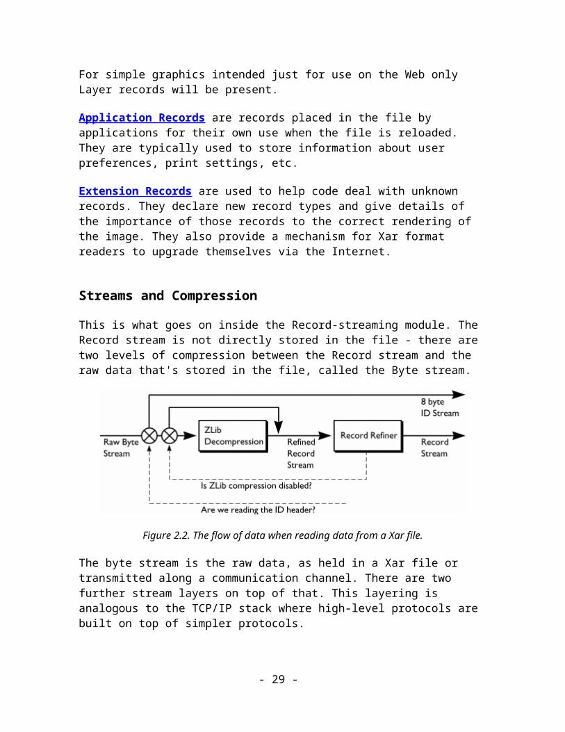
Streams and Compression
This is what goes on inside the Record-streaming module. The Record stream is not directly stored in the file - there are two levels of compression between the Record stream and the raw data that's stored in the file, called the Byte stream.
- 21 -

Figure 2.2. The flow of data when reading data from a Xar file.
The byte stream is the raw data, as held in a Xar file or transmitted along a communication channel. There are two further stream layers on top of that. This layering is analogous to the TCP/IP stack where high-level protocols are built on top of simpler protocols.
To explain the streams a little more easily, let's consider the process of reading a Xar file and extracting useful records from it.
Byte Stream
Normally receiving the raw Byte Stream is the Zlib decompressor. This can be switched on or off by the reader when it receives compression control records in the Record stream. The output from the Zlib decompressor is a stream of Refined Records.
Refined Record Stream
The Refined Record Stream is passed into the Record Refiner which "un-refines" the records (it gets the name "Record Refiner" from the job it does when writing a Xar file) to produce the normal Record Stream described above in Records. The Record Refiner operates on records in a number of ways:
1. By altering records to compress better in Zlib.2. By changing or removing records whose information is redundant for
one reason or another.
The ability to use different Refining techniques on individual Xar files is built into the format.
Record Stream
Each record is dispatched according to its Tag to the appropriate record handler.
These two stages of compression and decompression are the key to the compact size of the Xar format. Zlib performs byte-level, "micro"-compression and the Record Refiner performs record-level, "macro"-compression. On top of those stages there's also a level of
- 22 -

human compression in which the designers of the records have ensured that Records are size-efficient.
Zlib is a licence-free public domain library that performs LZW-like compression. The use of this library allows the Record stream to use "wide" fields, making them easy to parse and future-proof. The 32-bit Tag field of the Record header is a good example: Parsers don’t have to worry about escape sequences being used in the future to make the field bigger, since the 4 Billion possible values it can hold will supply all the Tags that can possibly be required in the lifetime of the format.
Note: The ability to control whether the first Zlib compression stage does anything or not means that Xar files consisting entirely of an open Record Stream are legal. They wouldn't normally be used in the real world because they will be significantly bigger than their compressed equivalent. However, they are very useful when debugging Xar format readers and writers.
The format is designed so that no look-ahead is needed - when implementing either Readers or Writers you shouldn't need to seek through Byte Streams or Record Streams. This fundamental feature is one of the things that make progressive rendering possible.
Trees and subtrees
The Record Stream includes Navigation Records that conceptually organise the records into a tree structure. (Readers that are used to prepare Xar documents for editing by users should use this information to create a tree data structure in memory. Readers that intend simply to render Xar files don't need to do this.)
The tree structure is the fundamental data structure used by all illustration programs (that is, programs that create vector graphics). Vector graphics images gain their richness by arranging and overlaying a number of simple graphical objects. The best real world analogy to this is the collage. The user creates many arrangements of objects in the process of drawing an image and the illustration program creates some itself. It is convenient for many of these arrangements of objects to behave as single entities and the tree structure allows several objects to be collected together as children of a root object. The root object can then be manipulated as a single object and it instructs its children how to behave.
This composition of objects is very convenient both for the user and for programs that have to deal with the graphic. The user can draw a boat and group all the objects that make up that drawing, naming the group "Boat". He can now treat that group of many simple objects as if it were one simple "Boat" object. The act of grouping creates a subtree whose root is an object called a Group.
The program uses the tree structure to hold complex objects together. For instance a text object might be the root of a subtree that contains one or more lines of text. Further, each Line might be a subtree that contains one or more characters.
- 23 -

The tree structure extends much further than just representing composite objects for the user. In the Xar format, what the user sees as being simple graphical objects are usually, in fact, composite objects. The user's simple objects, such as rectangles and ellipses, need to be given individual colours, line widths, arrowheads, etc. if the image is going to be at all interesting. In the Xar format, the description of each of these Attributes is a separate Record and they are most frequently held in the subtree of the object they affect.
For example, here is the subtree that describes a green rectangle with a 4pt outline.
Figure 2.3. A subtree describing a green rectangle with 4pt outline.
Thinking more expansively, the entire document (or file) is a tree whose root is a "Document" Record. For example here are the records that you might find in a Xar format document which includes document-structure information.
Figure 2.4. Document-structure records in a Document tree.
- 24 -

Note that even the tree structure itself contributes to the compactness of the Xar format! Because attributes such as colour are not held inside the shape records, they can be placed in the tree where they have the best effect. For instance, a group consisting of 100 green circles does not put 100 "Green" records in the file - there is only one "Green" record, which applies to the whole group. The tree structure determines the scope within which the effect of the attribute applies.
The tree structure has other technical benefits for programs editing and rendering Xar files, which are outside the scope of this document.
The tree data structure can extend as much as it needs to, to encode the complexity of the graphic. Each Tree consists of a root Record and a list of zero or more Trees. The list of Trees is called the "child list" - those Trees are thought of as being the "children" of the Root record and they are often called "subtrees". You can see the recursive nature of this data structure: a tree can hold a tree can hold a tree, etc., etc…
- 25 -

Conventions
Data Types
Below is a list of the basic data types used in the file format:
BYTE Unsigned integer. 1 byte
UINT16 Unsigned integer. 2 bytes
INT16 Signed integer. 2 bytes
INT32 Signed Integer. 4 Bytes
UINT32 Unsigned integer. 4 bytes
FIXED16 Fixed point value with the binary point between bits 15 & 16. 4 bytes
DOUBLE Double-precision floating-point number in IEEE format. 8 bytes
FLOAT Single-precision floating-point number in IEEE format. 4 bytes
STRING Sequence of Unicode (2 byte) characters, terminated by two 0x0 bytes.
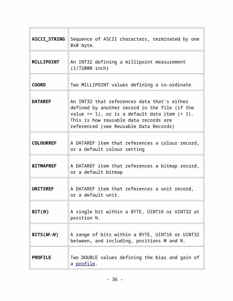
ASCII_STRING Sequence of ASCII characters, terminated by one 0x0 byte.
MILLIPOINT An INT32 defining a millipoint measurement (1/72000 inch)
COORD Two MILLIPOINT values defining a co-ordinate
- 26 -

DATAREF An INT32 that references data that's either defined by another record in the file (if the value >= 1), or is a default data item (< 1).This is how reusable data records are referenced (see Reusable Data Records)
COLOURREF A DATAREF item that references a colour record, or a default colour setting
BITMAPREF A DATAREF item that references a bitmap record, or a default bitmap
UNITSREF A DATAREF item that references a unit record, or a default unit.
BIT(N) A single bit within a BYTE, UINT16 or UINT32 at position N.
BITS(M-N) A range of bits within a BYTE, UINT16 or UINT32 between, and including, positions M and N.
PROFILE Two DOUBLE values defining the bias and gain of a profile.
Record Description
A Record is described by the following standard layout:
Name Name of Record or group of Records
Purpose Short description of the purpose of the record(s).
Tag Tag Identifier(s)
Size Size of record if fixed or "variable" if not
- 27 -

Usage What group the record belongs to and the conditions under which it should be used.Navigation: It's a Navigation recordFramework: It's a Framework recordImage: It's an Image recordApplication: it's an Application recordExtension: It's an Extension record.Compulsory: A Xar Reader or Writer must understand this type of record (under qualified conditions).
Data: <This part only appears when the record has a data section.>
Field name and type Field details, including legal possible values
Comments: <This part is optional.>
Further comments about the record.
The meaning of the symbols used in record definitions
Data sections within the record are defined using the following symbols.
Notation Description
<Name> An element in the file, usually broken down into more primitive elements
<Name : TYPE> An element and its type. The most primitive elements in the file are given a type (defined in the table above) and are not broken down any further.
[<Name>] Optional Element
<Name>* Zero or more occurrences of the element
- 28 -
<Name>+ One or more occurrences of the element
::= "Is composed of". Used to define one element in terms of more primitive elements
- 29 -

File structure
Byte ordering
Byte ordering is little-endian - the least significant byte of any size of word is stored first followed by the next least significant, etc…
So, a 16-bit word, 0xBBAA, appears in the (uncompressed) file as two bytes, 0xAA followed by 0xBB.
A 32-bit word 0xDDCCBBAA appears as four bytes, 0xAA, 0xBB, 0xCC, 0xDD.
Code to read or write Xar files on platforms which order bytes differently will have to swap the bytes around.
High-level Structure
The file format is very simple at the top level. It consists of an 8-byte ID at the start of the file (for quick identification), followed by a contiguous stream of records. The first record in the file is always guaranteed to be the file header record, and the last record is always guaranteed to be the End Of File record. This EOF record is present purely for file validation purposes, i.e., if you don't find one something has gone wrong.
Figure 4.1. The format of the file.
The 8-byte ID consists of two 32-bit numbers, 0x41524158 and 0x0a0dA3A3. The first number contains the characters "XARA". The second contains two top-bit-set characters (two '£' characters), plus a CR-LF combination. This second word will allow us to detect file corruption through the intervention of a text editor (which would affect the CR-LF sequence) or 7-bit encoding (which would remove top-bit-set characters) very quickly and safely.
- 30 -

Records
At its simplest, the Xar format is made up of a flat sequence of elements called Records. Each record is made up of the same three fields.
Figure 4.2. The fields of a record.
The fields of a record have the following meanings:
Record Tag: A 32-bit unsigned integer that uniquely identifies the record, and its contents.
Record Size: A 32-bit unsigned integer specifying the size of the data section. A size of zero means there is no associated data with this record. The size of the data section can be fixed or variable. The size is measured in bytes.
Data (Optional): The data associated with the record. The content of this section depends on the Tag of the record.
With this structure it is possible for the format to be backward compatible. Format readers that don't understand a given record Tag can skip the entire record by using the value of the Size field.
The Tag Guarantee
The Tag determines the type or class of the record. The size of the Tag field has been defined as a 32-bit unsigned integer in order to give the format a practically inexhaustible range of tag values (about 4 billion of them). With this huge range of possible tags, the format guarantees that the contents of a data section of a given record Tag will remain fixed forever. This helps the format to be forward compatible. Once a record with a given Tag has been defined, its content is guaranteed to be fixed, allowing readers of future versions of the format to still recognise and read old records.
- 31 -

You may be wondering how, in that case, records are updated to carry new information - a common requirement because graphics programs are being continually developed. The answer is that a completely new Tag is defined whose record carries the same information as its predecessor along with whatever new information is required.
Using Diverse Tags to Aid Compression
The other advantage of having such a wide range of tags is that it allows the Data sections of records to avoid holding optional fields that might not always contain useful information. Instead, separate Tags define separate record types, each of which contains a different set of the optional fields. This feature helps to improve the compactness of the format.
A good example is a rounded rectangle record (i.e. a rectangle that has rounded corners). As a rectangle and a rounded rectangle are almost identical, you might, at first think it logical to define one record that describes both types of object. However, rectangles are far more common than rounded rectangles and this approach would mean every rectangle would contain redundant roundness data - adding wasted data to the Xar file. A more space-efficient approach is to define separate rectangle and rounded rectangle records, eliminating the need to store redundant data for simple rectangles.
Tree Structure
A mechanism has been defined that organises the records into a tree structure. The tree structure is used to make composite objects out of simpler objects. For instance, a Document is made out of one or more Chapters. In this example, the Document is the root of the tree and the Chapters are its children. Each Chapter can itself be a tree (when a tree is a child of a higher tree it's often called a "subtree").
The order in which objects are organised in this tree structure determines the order in which they are rendered.
- 32 -

Figure 4.3. How records are named within the tree structure.
The above illustration shows several records organised in a tree structure. It details how records are named in relation to the record that's highlighted by the dotted line.
A record can have siblings. Left siblings appear before it in the file. Right siblings appear after it.
A record can have a parent. A record can only have one parent, which appears before it in the file.
A record can have children. A record can be the parent of one or more child records. Child records appear after it in the file.
Special records are defined that impose this tree structure onto the flat sequence of records. These are called Navigation records and they consist of an Up record and a Down record. They control the "level" of the records in the tree. The top level is numbered 1, the next level down is numbered 2, etc. For each Down record there must be a matching Up record later in the file.
Here is a set of records, labelled A to F, organised within a tree structure:
Figure 4.4. A tree of records, and the level on which each record lies.
Using the Navigation records, the above tree can be defined using the following flat sequence of records:
A Down C D Up B Down E Down F Up Up
When reading the file, the interpretation of this sequence of records is this:
Record read in What to do
- 33 -

A Interpret record A. The first record is always on level 1
Down Go down to level 2. The following record is a child of A
C Interpret record C
DInterpret record D. This record must be a sibling of the previous record (and therefore a child of record A), because a navigation record has not been encountered prior to it.
Up Go up to level 1. The following record is a sibling of record A (i.e. a sibling of the last record on this level).
B Interpret record B
Down Go down to level 2. The following record is a child of B
E Interpret record E
Down Go down to level 3. The following record is a child of E
F Interpret record F
Up Go up to level 2. The following record is a sibling of record E
Up Go up to level 1. The following record is a sibling of record B
The navigation records thus describe a tree, informing the Reader of the file how the tree is built up. The tree structure is an important aspect of the format, determining the order in which objects are rendered, and controlling the way attributes are applied to objects.
Rendering Order
A subset of records within the format defines the renderable elements of the file. These renderable elements are either objects (i.e. graphical elements such as rectangles and curves) or attributes that effect the appearance of the objects (such as the colour of the
- 34 -

rectangle, or the line width of the curve). These records are sometimes called Image Records.
The tree is rendered in a left-to-right, depth first order. In other words, starting from a given object, you render the object's children, followed by the object itself, followed by its right sibling. Using this algorithm, the rendering order of the tree in the above diagram, Fig. 4.4, is C, D, A, F, E, B.
Attributes in the Tree
Attributes are Image records that don't render anything directly - they just define some information which Image records will use to alter their appearance. The most typical example of an attribute is a record that sets the colour of an object.
Scope
Attributes have a well-defined scope within which they can affect the objects being rendered. The basic rule that determines an attribute's scope is this: An attribute can only affect objects in the same subtree as itself including its parent object. Outside of that subtree the attribute has no effect whatsoever. (In reality the depth-first rendering algorithm causes the rule to be a little bit stricter than this. See Rendering Attributes below.)
Returning to the example tree in Fig. 4.4, objects C and F might typically be attributes. In that case their scope of influence would be as shown below:
Figure 4.5. The scopes of Attribute C and Attribute F.
Attribute C affects objects D and A. Attribute F affects object E. Neither attribute affects object B because it is outside both of their subtrees.
- 35 -
Precedence
There are often cases where there are two or more attribute records in the tree, both trying to set the same type of rendering value, such as fill colour. Because of the rule given above, the only case where their scopes can overlap is when one attribute is inside a subtree that is already in the scope of another attribute. In that condition, the rule is the attribute in the inner subtree always takes precedence:
Figure 4.6. The precedence of attributes in nested subtrees.
Attribute B affects objects A and D. Attribute E affects objects C, F, G, H and I.
Effect Attributes
Xara Xtreme introduces the concept of “compound rendering”, where a collection of objects are not rendered directly into the document but are rendered into a bitmap instead and then that bitmap is rendered into the document. This opens up two new possibilities for rendering:1. The bitmap can be processed by applying bitmap effects to it (e.g. Photoshop plugins) before it is rendered into the document.2. The bitmap can be rendered into the document using different attributes than were applied to the original objects.
The attributes in the second case are called “effect attributes”. They are normal attributes, they use the scoping rules described above but they are stored in the document tree in a different position than normal attributes. Looking at figure 4.6.1 below B is a normal attribute and D is an effect attribute. D is stored at the right hand end of the sibling list,
- 36 -

after all other objects and attributes. Thus, according to the scoping rules it only affects its parent object, object A.
Figure 4.6.1 The position and scope of an effect attribute.
Effect attributes are only applied to those objects that understand them, for instance LiveEffects and Groups. These objects look for effect attributes in the tree, to the right of all other children of the object, and use them when rendering bitmaps back into the document.
Attributes in Xara Programs
Xara Xtreme and all earlier versions of the Xara programs apply stricter rules to documents than the file format requirements set out above. This is done to ensure that attributes are stored optimally in the document tree for quicker rendering and easier editing:
Where the scopes of several identical attributes fill an encompassing scope they are removed and replaced by a single attribute that applies to that larger scope.
Attributes of the same type are not allowed to have overlapping scopes.
For example: If all the objects in a group have green fill colour attributes then those attributes are removed and the group itself is given a green fill attribute. The scoping rules mean that this one new attribute has the same effect as all the original ones. If the user then selects one object inside the group and gives it a red colour attribute the group’s green attribute is removed and individual green attributes are applied to all the objects in the group except the new red one. (See fig. 4.6.2.)
- 37 -
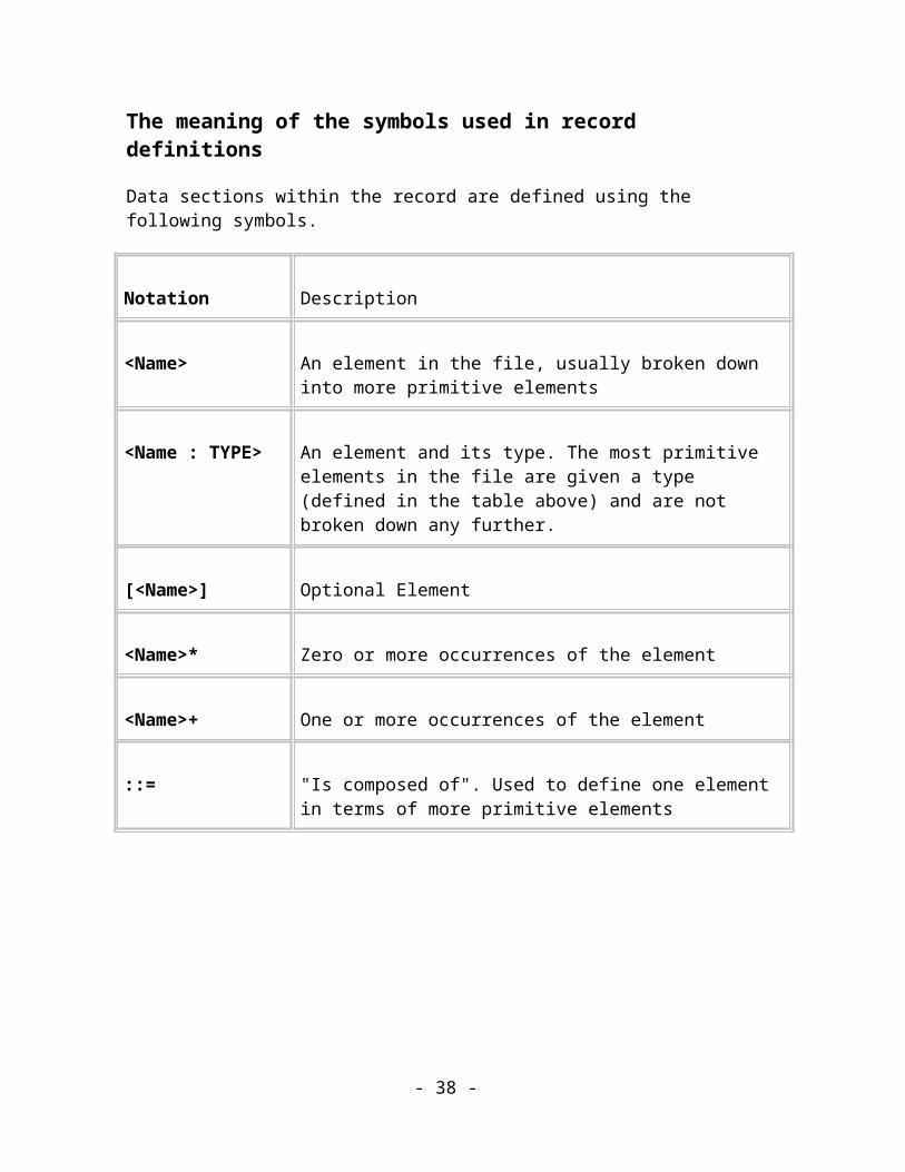
Figure 4.6.2 Attribute optimisation in Xara programs.
The editing functions of the Xara programs assume that records in XAR format files will have been optimised in this way. If they are not you may see odd effects when you edit the document, such as colour changes.
See the “Attribute Application, Optimisation and Integrity” document for more information.
Rendering Attributes
The Rendering Context
During rendering, a Rendering Context is maintained which describes all the current attribute values. This is similar to the Device Context found in windows programming environments and the current graphics state in Postscript. This Rendering Context can be saved and restored on a stack of contexts using a similar technique to Postscript's gsave and grestore commands.
- 38 -

When an object is rendered all of the graphical attributes it needs, such as line width, dash pattern, fill colour, etc., are fetched from the Rendering Context and used to render the object.
Rendering Attribute Scope
During the normal depth first rendering scan of the tree each Attribute record is encountered and is asked to render itself like any normal Image record. To render itself an Attribute sets its value to be current in the Rendering Context. Thus any objects that are subsequently rendered will pick up that attribute's value and use it.
The Scope of the Attribute is implemented using the ability to save and restore the rendering Context.
When the parent of a subtree is entered in the depth first scan the current attribute context is saved onto a stack before any of it's children are rendered (c.f. Postscript's "gsave" command).
Next all of its children are rendered, including any attributes, which set their values in the current Rendering Context.
Once all the children have been rendered the parent of the subtree is rendered, using any attribute values set by its direct children.
Finally, before moving on to another subtree the Rendering Context that was preserved on the way into that subtree is restored (c.f. Postscript's "grestore" command). Thus, any attribute values that were set inside the subtree are wiped away by the preserved values and the attribute context for the next subtree is unaffected by anything done inside this subtree.
As you can probably see, the fact that the attributes are rendered in strict tree order adds a small condition to the Attribute Scope rule given above: An attribute can only affect objects in the same subtree as itself and which follow the object in left-to-right depth first scanning order including its parent object
By convention, attributes are always stored as the first records in any child list so that in practice they are the first records rendered in any subtree and so do affect all of the visible objects in the subtree.
Default Attributes
To be truly self-contained, every document should contain a list of default attributes in the child list of the Document object. These Default attributes would cause default values, such
- 39 -

as DashPattern:None, to be rendered early in the rendering process so that all attributes are given well-defined values before the first visible object is rendered.
However, to save space, the Xar format doesn't do this. If it did, every Xar file would carry inside it an identical list of 20-or-more attribute records. Instead, the default attributes are defined to have fixed values in Appendix B of this specification and all Xar readers should set these values up in their rendering systems before starting to scan the tree.
Notes about Common Data Types
Co-ordinates
The majority of records in Xar files carry some sort of positional information in them. Positions are specified by Cartesian co-ordinates with origin (0,0) and where x increases to the right and y increases upwards. The resolution of these co-ordinates is 72000 dpi. These units are sometimes referred to as "millipoints" because each one is one thousandth of a Point.
At 72,000 dpi a 32-bit co-ordinate can represent sizes of up to 1.5 kilometres. There are technical limitations which prevent that theoretical size ever being used. You are unlikely to find documents whose extent is greater than about 2m square.
Strings
All Strings that are visible to the user are stored as Unicode. This allows text in any language/script system to be stored in Xar files. The Zlib compression stage deals with the efficient storage of the two-byte Unicode character values.
Profiles
A profile is a mapping function for numbers in the range 0 to 1 that allow effects that usually change linearly to change in a number of more useful ways. The profile is defined by two DOUBLE values between the values -1.0 and 1.0 called "bias" and "gain". The actual functions used to perform the mapping are as follows.
Firstly the supplied bias and gain parameters are mapped to lie between 0.0 and 1.0 exclusive with the following function:
newvalue = ((oldvalue + 1) * 0.49999) + 0.00001
Then the mapping function is defined as:
- 40 -

map(x) = gain( bias(x) )
Bias and Gain values of 0 (0.5 after the conversion to 0 to 1 range) result in both the bias and gain functions reducing to identity functions.
Compression
Two stages of compression are applied to the Record Stream before it is written to file. Record Refinement works on the record level, removing redundant information and preparing records for the second stage, ZLib compression, which works on the byte level.
The Record Refiner
The Record Refiner is the compression stage that processes records before they reach the ZLib code in an attempt to improve the overall compression. The Record Refiner operates at a higher level of abstraction than the Zlib library. It operates on Records and uses it's knowledge of them and the Xar format to "refine" the record stream before passing it on to Zlib.
- 41 -

Figure 4.7. How record data is compressed and decompressed.
The above diagram shows how the Record Refiner sits between the format's Record Stream and the ZLib compression stage.
Refinement Methods
Refinement methods are designed to work at the record level. They take a single record as input, and produce zero or more records as output. If a Refinement method alters a record's data section, the resultant record will have a different record tag. This maintains the Tag Guarantee. There is a small set of specialised Records which only appear in the Refined Record Stream that communicates between Zlib and the Record Refiner - never in the normal Records Stream.
The Record Refiner can perform some generic work on all records passing through it but many methods of Refinement are very specific to the type of Record. For instance, the co-ordinates stored in Path records can be adjusted so that each co-ordinate is relative to the one before it. This makes the format of that Record much more suitable for compression by the Zlib stage. Specialised Refinement methods like this are described in the chapters of the appropriate Records.
Refinement Methods Flags Word
To allow new Record Refinement Methods to be used in future, the format defines a Refinement Flags Word that identifies which Refinement Methods have been applied to the Record Stream. This 32-bit word is held in the File Header record and at the time of writing it is defined to always be 0.
- 42 -

ZLib Compression
This is a form of compression that is similar to LZW compression in its technique and in its performance. It is available for use royalty-free, via a C library. It provides the final level of compression before data is written to the byte stream.
The compression scheme used is based around the Zlib specification that is used for the PNG (portable network graphic) file format. This is designed to get around the patent problems with the GIF and TIFF bitmap format compression code. Source code and formal definitions are available from http://www.gzip.org/zlib/ and the PNG format homepage at http://www.libpng.org/pub/png/.
The compression scheme is a lossless format which uses a combination of the LZ77 algorithm and Huffman coding to provide a scheme which is as efficient and effective as other present similar forms. It is designed to be stream based rather than requiring the entire set of data to be present. It uses a 32k sliding window, where a duplicate entry can be made to reference the original entry up to 32k input bytes beforehand.
Each block has an independent set of Huffman trees that consists of two parts: the definition of the compressed part and the compressed part itself and are output at the start of each block. The compressed part has either strings that are not duplicated (literals) or a length, backward distance pair which point to the original string. The lengths are limited to 258 bytes, the distances to 32k bytes.
Uncompressed blocks are limited to 65,535 bytes in size. Huffman encoding is used to then compress these trees. This is done by representing all the literal strings, the distance and length values as a Huffman code, one code for the literals and lengths and another for the distances.
Application of Zlib compression
ZLib never compresses the file header and EOF records. Zlib compression can be turned on (via a Start Compression record) any time after the file header record, but it is not guaranteed to be the next record after the file header. The data immediately following the Start Compression record is a ZLib compressed stream containing compressed records. The data should be decompressed and interpreted as records in the normal way (a 4 byte tag and a 4 byte size field). The last record in the compressed section will be an End Compression record but only the record header is in the compressed stream. The record data itself (the CRC and length values) is uncompressed hence this record requires some special handling. Compression is based on the public domain Zlib compression libraries. By making compression optional in this way it means that valid files can be written and understood by all Xar file readers. In some cases the added complexity of writing compressed .web files may not be warranted, and it often makes debugging easy to have non-compressed records. Secondly this system allows records that do not compress well (e.g. already compressed
- 43 -

bitmaps such as JPEG and PNG) to stay out of the system, and hence not mess up compression dictionaries etc.
Reusable Data Records
The Xar format has a very simple mechanism that allows an item of data to be specified once, and then to be referred back to many times instead of duplicating the data over and over again. The format contains many elements that are reusable in this way and this is another feature that contributes to the compact nature of Xar files.
Here is a list of some of them:
Bitmaps Colours
Fonts
Arrowheads
Reusable data is stored in the file in the same way as everything else, in a record. It is up to the Xar reader to convert reusable data records into a form that allows the reconstruction of the Xar graphic. For example, bitmaps are reusable but the bitmap record may not be in a directly renderable form - it may be stored in JPEG format. It is the Xar reader's job to convert these bitmap records into a form that's appropriate for rendering on the local system. In the case of a Xar reader implemented to run on Windows, it would have to convert the JPEG data into a DIB.
The important point when importing reusable records is that once any conversions into local format have taken place, that data should be preserved so that further records in the file can use it again. Records later the in the record stream may refer back to the records which originally created this data using a Sequence Number.
Sequence Numbers
As you know, the Xar format is made up of a contiguous stream of records. Thus, each record has an implicit, unique Sequence Number. The Sequence Number of the first record in the file is 1, the second is number 2, and so on. Sequence Numbers can be computed automatically by Xar readers and writers simply by counting the Records as they pass in or out of the Record Stream - so Sequence Numbers don't need to be saved in the records and this saves a little space.
Sequence Numbers are used by one record to refer to another. A record can only reference a record that appears earlier than it. This ensures that the file remains progressively
- 44 -

renderable because it disallows forward references to records might take a long time to become available.
Sequence Numbers are signed, 32-bit integers.
Writing Reusable Data Records
The writing of reusable records is driven by references to the data item rather than by the data itself. It works like this:
Each type of reusable data item has a Manager that maintains a database (or dictionary) describing which data items it has written during a Write session. This Manager can be called to hand out references to its data items for use inside other records. When asked for a reference, the Manager first looks it up in its database to see whether that item has already been output and, if so, it returns a reference to that reusable data record. If not, it writes the Reusable data item out there and then, and returns a reference to it.
From the point of view of the code which is asking for references, all it sees is the one "give me a reference to this item" call - the fact that that call sometimes writes records of its own is transparent.
This system ensures that reusable data items only occur once in a Xar file and that they only occur just before they're needed.
The reference to a reusable data record is its Sequence number. Since this is a signed 32-bit number (see below to understand why it is signed), this means that all Reusable Data Records must appear in the first 2 billion records of a file. This is unlikely to be a great limitation.
Reading Reusable Data Records
Reading reusable data is straightforward too. The only restriction is the obvious one that a reusable data record must appear in the file before it is referenced.
The reusable data item Manager receives a data item and stores it away ready for later references to it. At the same time it adds an entry to its database, linking the Sequence number to the data item stored in memory. The Manager provides a function call that takes a Sequence number and returns information about the reusable data item in memory to the caller.
Now, a routine interpreting a record which contains a reference to a reusable data item simply calls the appropriate data Manager simply calls that function, passing in the reference that it's extracted from the record. It should always get back the information it
- 45 -

needs about the referred data item because the Writing process defined above guarantees that the data item is placed in the file before the first reference to it.
Default Reusable Data Records
Some classes of data item may have a number of defaults - predefined data items that are commonly used. These defaults are bound into Readers and Writers so that they don’t need to be included in Xar files, saving a little more space. They are used by special Reusable Data references.
To signal that a reference refers to a Default Reusable Data item it is negative. All references >= 1 refer to a Reusable Data record within the file. All numbers < 1 refer to a Default Reusable Data Item.
The nice thing about this method is that a record that uses the reference has no idea whether it is a default item or not. For example, a flat fill colour record would ask the colour system for the reference value for a particular colour - it is not concerned what the value is, as long as the system can dereference the value during Reading.
The legal ranges of reference numbers for Default Reusable Data items are given in the sections describing the data.
Document Structure
So far we have seen that the records that appear in the file can represent a tree structure. Also, the idea of renderable records (namely objects and attributes) has been introduced, describing how the tree structure defines the way in which the records are rendered.
This section describes how the format uses those systems to encode the graphical environment within which the images themselves reside - the framework that holds the graphics in place. It introduces the ideas of Documents, Chapters, Spreads, Pages and Layers and explains why they are not always required.
Document Structure Records
The illustration below shows how the elements that define the document structure (i.e. the document structure records) are organised:
- 46 -

Figure 4.8. Diagram of the document structure hierarchy.
As the diagram shows, the elements of a document are defined using a set of records within the file. Each record type defines the head of a sub tree of records. (The tree structure is controlled using the Up and Down navigational records, as described earlier).
The document element records have the following meaning:
Document This record defines that all records in its sub tree belong to the same document. There can be more than one Document record in a file, allowing for multiple documents within one Xar file.
Chapter This groups a series of spreads together as a single unit. Each document can have multiple chapters.
Spread Each chapter can have multiple spreads. A spread simply defines a set of renderable objects that make up a single illustration. It can be thought of as a page, within a word processor. It is not called a page because it does not impose a single page size. A spread can be made up of several pages that are linked together. A good example of this idea is a double-page spread (DPS). This is two pages that are connected down one edge, representing a single area where objects can live, possibly overlapping the join of the pages. The spread will be shown on screen as a single drawing surface and when bound in a publication it will look that way. However, during the printing process each Page is printed separately.
Layer A spread can contain more than one layer. Each layer contains renderable objects. The most powerful aspect of a layer is that it can control the visibility of all
- 47 -
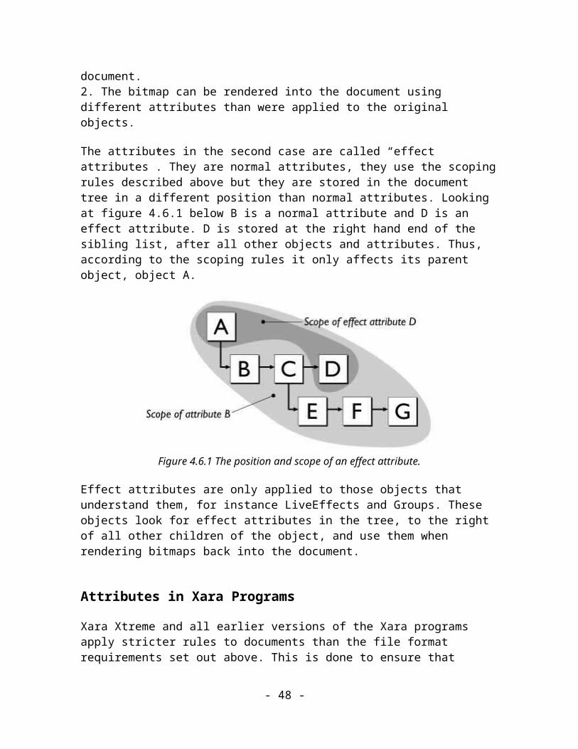
the renderable objects within it. Think of layers as acetate sheets laid over the drawing; you can draw on each sheet separately, remove sheets temporarily, put them back or change their order.
These records are known as the Framework Records. C.f. Image Records.
The document structure imposes rules on theorder in which records can legally appear in the file. For example; a Document record cannot be a child of a Chapter, a Spread cannot be the child of an object and so on.
When considering very simple files, this structure can be seen as a wasteful overhead. For a file that just contains one circle, the hierarchy would account for the majority of the file, without adding any renderable information. This is clearly not desirable for a graphic that is to be sent across the Internet.
It is therefore defined that the records used to structure the document are optional. When you encounter a record that is defined lower in the document hierarchy, you can assume the parent document structure records are implied. For example, if you read a Spread record before a Chapter or Document record, you can assume that it is part of a single document that contains a single chapter. Likewise, if you read an object or an attribute before any document structure records, the complete hierarchy is implied.
Once a higher level document structure record is implied, no records of that type can be legally present in the file. This means that if you come across a Spread record as your first record in the document hierarchy then later encountered a Chapter record, the Chapter record would be illegal (and the rest of the file should be ignored from that point on).
A Document record is required to delimit the start of the document if multiple documents are present in the file. If a Document record is implied then it is assumed that there's only one document in the file. At least one Layer record is required to hold the renderable objects.
This implied hierarchy approach gives the file format a rich, multiple document structure, without increasing the size of the file for simple web graphics.
Multi-spread documents
Note that up until July 2006 the Xara Xtreme application and its predecessors could only save documents containing single Spreads. After that date versions of Xara Xtreme can save documents containing more than one spread. See TAG_SPREAD and TAG_SPREAD_PHASE2 for details of back compatibility arrangements.
- 48 -

Other information in Xar files
Application Records
The editing application may wish to preserve information about the editing state of the file. Any such information will appear in the record stream after the Document record (if present) but before the first Framework record. A typical example of this type of record is a Print Settings record that defines how the document is to be printed. It would include information such as whether to print all layers or just the visible ones, whether the document has to be rotated to fit it on the paper, the number of copies to print, etc.
Extension Records
A set of records is defined which help a Xar Reader to deal with records that were not defined when the Reader was written. These Extension Records supply the Reader with information about possible new Record tags which tell it how to deal with them if it encounters them and some information about the Records that can be presented to the user. Extension records will also usually be placed early in a Xar file, before the first Framework Record.
- 49 -

Guidelines for implementersThis chapter offers a few suggestions about implementing Xar Readers and Writers. A Reader is a program that loads a Xar file and interprets the records within it. A Writer is a program that creates Xar files.
The XarLib Library
When using C++ (or any other language that allows linking to C++ static libraries) the easiest way to implement a Xar file Reader or Writer is to use the XarLib library. The library provides access to a Xar file at the record level for both the reading and writing of Xar format files. The library is responsible for handling the ZLib compression and certain other features of the format (e.g. atomic and essential records) leaving you to deal with interpreting or writing the records without having to worry about the low-level details.
The library is currently only available as header files and static libraries built with Microsoft Visual C++ 6 (multi-threaded C runtime versions for debug and release). Other versions, including source code that can be built on other platforms, should be made available shortly.
Download the XarLib Library (660 KB)
All of the files in this download are copyright Xara Group Ltd 2005. You are free to use them for any purpose.
Suggestions for implementing a Xar Reader
To implement a Xar file Reader you first need to set up the two levels of compression. The best way to do this is to create three streams, which feed data from one into the other; byte stream to refined record stream to record stream. The Records stream, at the top of the stack, is what the Xar parser reads records from, one by one.
The Xar Parser requests the next record from the Record stream. The Record stream, in turn, requests the next record from the Refined Record Stream, the Refined Record stream requests bytes from the Zlib decompressor which, finally, requests bytes from the raw byte stream.
Once you've got the stream stack set up, you can start work on the Parser. To see results quickly, pick out the simplest graphical objects, paths, since paths are very familiar objects and their description in the file format is relatively straightforward. You can insert the paths into your data structure or render them (without worrying about attributes at this stage).
- 50 -

Beyond this stage there are several directions in which development could continue. We recommend that you set up a handler to deal with unknown records fairly early in the development process as a safety net and so that it can be tested on unimplemented records.
Suggested stages of Development
When using the XarLib library stages 1, 2 and 7 are handled for you leaving you to deal with the parsing of the required records.
Stage 1 - Obtain Zlib from http://www.gzip.org/zlib/ and implement the Zlib decompression stage.
Stage 2 - Implement code to deal with the Record Stream and the Refined Record Stream.
Stage 3 - Parse Path Records (includes some record Refining due to Path Similarity and relative coordinates)
Stage 4 - Parse Up and Down Records
Stage 5 - Set up default attribute values and parse simple attributes
Stage 6 - Now implement a renderer to see what you get
Stage 7 - Implement your handling of unknown records
Stage 8 - Now do all the remaining records that you need to understand
Here are some issues to be aware of:
Attribute stack
To implement the scopes of attributes correctly (see Attributes in the Tree) you need to implement some system which preserves the state of all attributes when a Down record is encountered and restores it when the matching Up is encountered. Obviously, you are free to implement this in whatever way you see fit but if you're rendering the drawing directly from the Xar format data structure the performance of such a system is very important. Down and Up records are the most common records in the file format so you need to think about the speed and efficiency of actually storing the attribute state every time a Down record is encountered.
- 51 -
"Un-refining" Paths
One element of the Path Record Refiner looks for paths that are similar to paths that it has already written and saves space by writing a back reference to the original path. Therefore, a Xar file Reader must keep track of all path records that it encounters so that when one of the back references is encountered it can repeat the appropriate path in the illustration.
The same kind of advice applies to the other re-usable records : bitmaps, colours, font specifications, etc.
Reading large records
Some records, for example bitmap records, can be very large. Creating a full Bitmap record can require a large amount of temporary memory - especially if you need to convert the bitmap data into a different format before you can use it. (For example, reading a large JPEG record and converting it into a DIB before being able to render it in Windows.) If that's a problem for your implementation, consider creating a system that allows the data section of large records to be read directly from the byte stream and streamed into the format converter so that a much smaller amount of temporary memory is needed.
Coordinates
Coordinates in Image Records are stored either relative to the bottom left of the Page or the bottom left of the Spread pasteboard.
The Reader can derive the size of a spread and the position of pages within it from the TAG_SPREADINFORMATION record.
Note that none of the Framework Records store any absolute coordinates – it’s up to the XAR Reader to set a position in space for the Chapters and Spreads that it reads. If the Reader handles more than one spread it is recommended that spreads are assigned coordinates that don’t overlap with each other.
Suggestions for Implementing a Xar Writer
It is more difficult to offer suggestions about implementing a Writer because that very much depends on the data structures from which the file must be constructed. It is likely that Xar Writers will be implemented in existing programs where data structures are well established and those data structures will fit the Xar graphics model to a greater or lesser extent. The closer the existing data structure is to the Xar model, the easier it will be to implement a Xar Writer.
- 52 -

Using the XarLib library will still reduce the development time considerably as it handles the compression and output layers and allows the Xar format to be created at the record level leaving you to concentrate on which records should be output.
Here are some issues to be aware of:
Layout of a legal Xar file
A legal Xar file must start with an eight-byte ID block, followed by a TAG_FILEHEADER record. The last record in the file must be a TAG_ENDOFFILE record.
Algorithms
This spec describes many of the algorithms required to convert the data contained in Xar records into rendered graphics but not all of them. The following programs are available which load Xar format files:
Xara X and related family of products, such as X1 and Xara Xtreme, are fully featured illustration programs able to render and edit all parts of a Xar file. Commercial application.
Xara plug-in. This is a Netscape plug-in that allows Xar format files to be displayed in web browsers. It does not support the full range of records in the Xar format (anything with a tag number of 4050 or higher will be ignored). It is only available for Windows and does not work in recent versions of Microsoft Internet Explorer (versions 5.5 and above). It can be downloaded from the Xara web site.
You can investigate the visual effects of the algorithms these programs use by loading Xar files created by your own Writer. The Xara plug-in is based on significantly different code from Xara X¹ and can thus provide useful additional test results.
Attribute scoping
Use the attribute scoping rules to control the area of effect of attributes. Place attributes in the subtrees in which their effect is required by using Down and Up records rather than placing them alongside the objects they're intended to affect.
Writing large records
Some records, for example, bitmap records, can be very large. Creating a full Bitmap record can require a large amount of temporary memory. If that's a problem for your implementation, consider creating a system that allows the record header to be created and
- 53 -
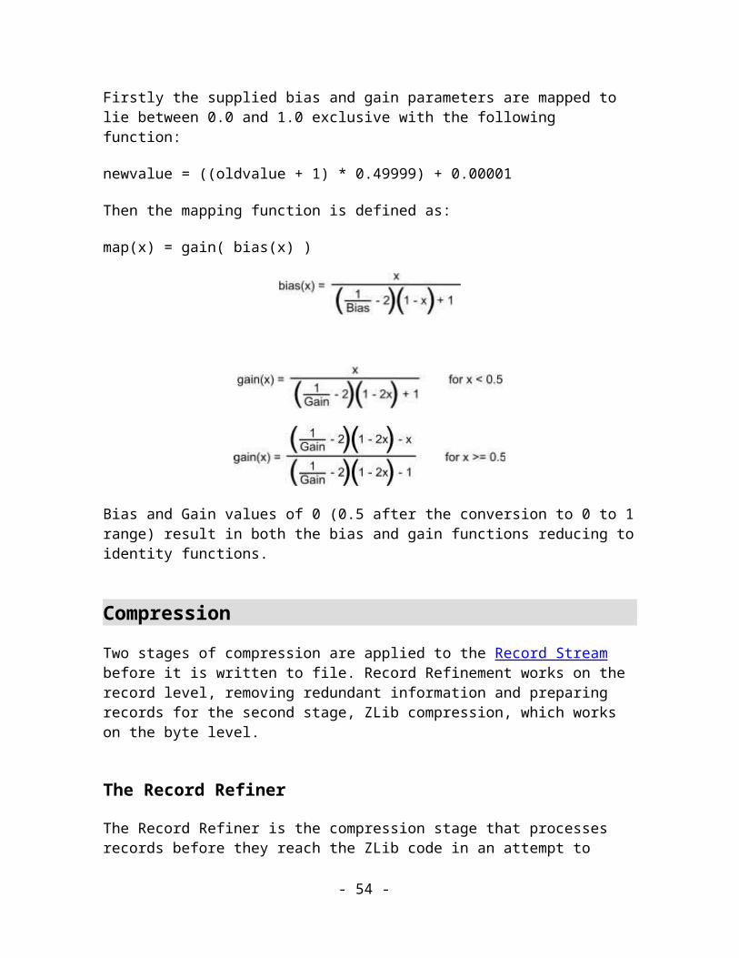
written to the byte stream separately from the data section of that record, which can be written directly to the byte stream, bypassing the record streams.
Files don't have to be compressed
Xar files don't have to be compressed. You can leave out the Start Compression and End Compression records, don't run Zlib compression between them and the output file will be perfectly legal. This isn't very useful for transmitting the file over the Web but it can be very useful for debugging purposes.
- 54 -

Navigation RecordsNavigation records impose a tree structure on the Record Stream. The tree structure is essential to the correct interpretation of the image and so cannot be ignored. It gives scope to attribute application and determines the composition of complex objects from simpler ones.
Name Down
Purpose This record defines that the following records are one level down in the tree structure - they are children of the previous record.
Tag TAG_DOWN
Size 0
Usage Navigation, Compulsory
Comments:
This record says that everything after this record will be a child of the previous record in the data stream until an Up record is found. An Up record further on in the stream should always accompany it.
Name Up
Purpose This record defines that the context should move up to the previous level in the tree.
Tag TAG_UP
- 55 -
Size 0
Usage Navigation, Compulsory
Comments:
This record defines that the context should move to where the previous Down record was encountered. It should always be accompanied by a preceeding down record.
- 56 -
Framework RecordsThis chapter describes all the Framework Records - those records which don't contribute directly to the definition of the image but which describe the context within which the image exists.
Many of these records are optional and are used more frequently in paper-publishable files than in files intended purely for Web use.
File delimiters
Name File Header
Purpose This record gives useful information about the file. This should always be the first record in any file produced.
Tag TAG_FILEHEADER
Size Variable
Usage Compulsory, Framework
Data:
<FileType : 3 BYTES>The type of information this file contains. This field backs up the information given by the file extension and is a more reliable indicator than the extension.
File type := CXW | CXN
CXW = Web file
CXN = Paper-publishable file
All other values are reserved for future use.
- 57 -

<FileSize : UINT32> The uncompressed size of this file, 0 if unknown.
<WebLink : UINT32 > Always 0x0. Reserved for future use.
<RefinementFlags : UINT32>
A flags word that describes which Refinement methods have been applied to this file.
<Producer : ASCII_STRING>
The name of the program that produced this file e.g. 'CorelXARA'.
<ProducerVersion : ASCII_STRING>
The version number of the program that produced this file e.g. '1.1'.
<ProducerBuild : ASCII_STRING>
The build number of the program that produced this file e.g. '650'
Comments:
This record gives useful information about the current file such as the name, version and build of the producer program and what type of document is contained within this file: native, web or template. This should always be the first record in the file, and is not compressed by the Zlib compression stage.
FileType: This contains three characters that describe the type of file. This is so that the file can be identified even if the file extension (i.e. type ID) gets lost.
FileSize: This is an estimate of the uncompressed file size of the file, in bytes. Zero means that there is no estimate. This is here purely for progress bar display.
RefinementFlags: These flags define which Refinement methods have been applied to this file (see the section on Refinement for more details).
Producer strings: These three strings combine to identify which program produced the file. They are stored as ASCII rather than Unicode in order to save file space (remember this record is not compressed).
- 58 -
Name End Of File
Purpose This record indicates that there are no more records in this file. This should always be the last record in any file produced.
Tag TAG_ENDOFFILE
Size 0
Usage Compulsory, Framework
Comments:
The record is for validation purposes only. If the end of the byte stream is reached before reading this record, then the file is corrupt in some way.
Compression records
These define the start and end of Zlib compressed sections in the file. Compression can be turned on and off multiple times in the file. Each Start Compression record must be matched by an End Compression record.
The Start Compression record also starts Record Refinement. This imposes the restriction that Record Refinement can never be applied without ZLib compression, although it is thought that this is not a significant restriction. (The Record Refinement methods that are to be applied are defined in the file header record by the Refinement Flags field.)
Name Start Compression
Purpose This record defines the start of a compressed set of data.
Tag TAG_STARTCOMPRESSION
Size 4
- 59 -

Usage Framework. Compulsory for Readers
Data:
<CompressionVersion : 3 BYTEs>
The version of the compression used.
<CompressionType : BYTE>
The format of the compression used.
Comments:
This record indicates that all data after this record will be ZLib compressed (and refined by the methods defined by RefinementFlags in the file header) until the End Compression token is found in the compressed stream.
At present the compression type is zero and this defines the use of ZLib.
The compression version is the version number of the compression system in use, multiplied by 100. It is stored as three ASCII number characters. E.g. v0.94 is stored as 094.
Name End Compression
Purpose This record defines the end of a compressed set of data.
Tag TAG_ENDCOMPRESSION
Size 8
- 60 -
Usage Framework. Compulsory for Readers
Data:
<CompressionCRC : UINT32>
A checksum or CRC for the compressed section.
<NumBytes : UINT32> Number of compressed bytes
Comments:
This record stops compression. It will only be found in the compressed stream. This always comes sometime after a matching Start Compression record .
The data section is actually stored outside the compressed stream. For this reason, the record needs some special handling.
Document Structure Objects
These are the objects that define the document structure, i.e. the document, chapter, spread, page and layer records.
Name Document
Purpose This record defines the start of a new document.
Tag TAG_DOCUMENT
Size 0
Usage Framework, not required in Web files.
Comments:
- 61 -

This record defines the start of a new document. It is not required by default. Always found before a chapter record, it is usually the first object record as opposed to a header record in the file.
Name Chapter
Purpose This record defines the start of a new chapter.
Tag TAG_CHAPTER
Size 0
Usage Framework, not required in Web files.
Comments:
This record defines the start of a new chapter. It is not required by default. It is always found after a document record and before a spread record.
Name Spread
Purpose This record defines the start of a new spread.
Tag TAG_SPREADTAG_SPREAD_PHASE2
Size 0
- 62 -

Usage Framework, not required in Web files.
Comments:
This record defines the start of a new spread. It is always found before a page record and after chapter and document records, if they are present in the file.
TAG_SPREAD is used in documents containing just a single spread.
TAG_SPREAD_PHASE2 is used to represent spreads after the first spread in the multi-spread documents. So, the list of Spreads in a 3-spread document would be written into the XAR file using these tags:
TAG_SPREADTAG_SPREAD_PHASE2TAG_SPREAD_PHASE2
This combination of tags allows old XAR Readers that may be unaware of multi-spread documents to load those documents successfully, retaining just the first spread in the document and skipping the others.
Name Spread Information
Purpose This record defines information about the current spread.
Tag TAG_SPREADINFORMATION
Size 17
Usage Framework, not required in Web files.
Data:
<Width : MILLIPOINT> The width of the page.
- 63 -

<Height : MILLIPOINT> The height of the page.
<Margin : MILLIPOINT> The margin to add around all four sides of the pages in the spread to make up the pasteboard.
<Bleed : MILLIPOINT> Bleed margin to add around all pages in this spread. (0 means none)
<SpreadFlags : BYTE> Flags for the current spread.
SpreadFlags ::= <DoublePageSpread : BIT(0)><ShowDropShadow : BIT(1)><SelectedSpread : BIT(2)><PrintWholeSpread : BIT(3)><NegateX : BIT(4)><NegateY : BIT(5)>
DoublePageSpread flag to say whether the spread consists of one page or two pages butted together beside each other.
ShowDropShadow flag to say whether we apply a page shadow behind the page.
SelectedSpread flag marks the spread that the user last clicked on. Note that it’s possible for none of the spread records in a XAR file to be marked with this flag. In this case, if the XAR Reader takes note of this flag at all, it should select one of the spreads by default (typically the first spread).
PrintWholeSpread flag to say if a double page spread should always be treated as a single page. E.g. if you have a double page spread and you ask for just page 1 to be printed, if this flag is set then both pages of the spread should be printed.
NegateX and NegateY flags to say if the coordinates displayed to the user for this spread should have there sense reversed (usually positive is to the right and upwards).
Comments:
This record defines extra information for the current spread. Always found after a spread record. It is not required by default. The same bleed and drop shadow style is applied to all objects in the spread. The margin is applied around the sides of the bounding box for all the pages in the spread.
- 64 -
Name Spread Animation Properties
Purpose This record defines animation properties for the current spread.
Tag TAG_SPREAD_ANIMPROPS
Size 28
Usage Framework, not required in Web files.
Data:
<Loop : UINT32> Number of times the animation should loop. (0 means loop indefinitely)
<GlobalDelay : UINT32> Default frame delay in milliseconds.
<Dither : UINT32> Dither type.
<WebPalette : UINT32> Class of palette (0 - global, 1 - local)
<ColoursPalette : UINT32> Type of palette (0 - browser, 1 - optimised, 2 - standard).
<NumCols : UINT32> Number of colours wanted in palette.
<Flags : UINT32> Animation flags.
Flags ::= <SystemColours : BIT(0)> <OpaqueBackground : BIT(1)>
SystemColours flag to say whether the palette should include the system colours.
- 65 -

OpaqueBackground flag to say whether the frames should have transparent backgrounds.
Comments:
This record defines extra information for the current spread. Always found after a spread record. It is not required by default.
Name Flash Animation Properties
Purpose This record defines Flash animation properties for the current spread.
Tag TAG_SPREAD_FLASHPROPS
Size 12
Usage Framework, not required in Web files.
Data:
<FramesPerSec : UINT32> Numbr of frames per second
<FlashVersion : UINT32> Flash version number (4, 5, 6 or 8. All other values are reserved.)
<Flags : UINT32> Flash animation flags
Flags ::= <ZLIBCompression : BIT(0)>ZLIBCompression flag to say whether ZLIB compression is enabled in the flash file.All other bits are reserved and should be set to 0.
Comments:
- 66 -

This record defines extra information for the current spread specifically for use when exporting the document as a Flash animation. Only present when Flash animation properties have been altered and then always found after a spread record. It is not required by default.
Name Page
Purpose This record defines a page within the current spread
Tag TAG_PAGE
Size 20
Usage Framework
Data:
<BottomLeft : COORD> The bottom-left co-ordinate of the page
<TopRight : COORD> The top-right co-ordinate of the page.
<Colour : COLOURREF> The Sequence Number of the record that defines the page’s colour
Comments:
This record defines a page that is associated with the current spread. The colour is defined by the colour record referenced by the ‘Colour’ field.
- 67 -
Name Layer
Purpose This record defines the start of a new layer.
Tag TAG_LAYER
Size 0
Usage Framework. Compulsory.
Comments:
This record is the parent of all the records in that layer.
Name Layer Details
Purpose This record defines aspects of the following layer in the file.
Tag TAG_LAYERDETAILS
Size Variable
Usage Framework. Compulsory for Readers. Not required in Web files.
Data:
<LayerFlags : BYTE> Flags defining aspects of the layer.
- 68 -

<LayerName : STRING> The name given to the layer.
LayerFlags::= <IsVisible : BIT(0)> <IsLocked> : BIT(1)> <IsPrintable> : BIT(2)> <IsActive> : BIT(3)>
IsVisible is set if the layer is visible by default.
IsLocked is set if the layer cannot be selected by default (it’s locked against editing).
IsPrintable is set if the layer can be printed by default.
IsActive is set if the layer can have new objects created in it by default.
Comments:
This record defines more detailed information about a layer. Always found after a spread or a page object (if a page is present).
Name Guide Layer Details
Purpose This record defines aspects of the following layer. It also defines the layer to be a guide layer
Tag TAG_GUIDELAYERDETAILS
Size Variable
Usage Framework. Compulsory for Readers. Not required in Web files.
Data:
<LayerFlags : BYTE> Flags defining aspects of the layer.
- 69 -
<LayerName : STRING> The name given to the layer.
<LayerColour : COLOURREF>
The colour used to display this guide layer.
LayerFlags::= <IsVisible : BIT(0)> <IsLocked : BIT(1)> <IsPrintable : BIT(2)> <IsActive : BIT(3)>
IsVisible is set if the layer is visible by default.
IsLocked is set if the layer cannot be selected by default (it’s locked against editing).
IsPrintable is set if the layer can be printed by default.
IsActive is set if the layer can have new objects created in it by default.
Comments:
This record defines detailed information about a guide layer. Always found after a spread or a page object (if a page is present). The guide layer is special in that this is where all the guide-lines are placed. There is usually only one, it is never printed and it can have a display colour defined to it. It can act like another layer, as in other objects can be placed onto it, but these objects are only displayed in outlines using the guide layer colour and dash pattern.
Name Guide-line
Purpose This record defines vertical and horizontal guide-lines.
Tag TAG_GUIDELINE
Size 5
Usage Framework. Compulsory for Readers. Not required in Web files.
- 70 -

Data:
<Type : BYTE> Whether the guide-line is vertical (1) or horizontal (2).
<Ordinate : MILLIPOINT> The guide-line’s offset from the spread origin.
Comments:
Although the same effect can be achieved by creating horizontal and vertical lines in the guide layer, this record offers a shortcut and saves file space for these commonly defined guide-lines.
Name Layer Frame Properties
Purpose This record defines animation properties for the current layer/frame.
Tag TAG_LAYER_FRAMEPROPS
Size 5
Usage Framework, not required in Web files.
Data:
<Delay : UINT32> Time this frame should be displayed for in milliseconds.
<Flags : UINT32> Animation flags.
Flags ::= <Solid : BIT(0)> <Overlay : BIT(1)> <Hidden : BIT(2)>
Solid flag to say whether this frame should completely obscure those before.
- 71 -

Overlay flag to say whether this frame should be overlayed.
Hidden flag to say whether this frame should not be shown.
Comments:
This record defines the animation properties of the current layer/frame. It is not required by default.
View records
These are records which define the views onto the document and their status information.
Name View Port
Purpose This record describes the viewing area that should be shown by default.
Tag TAG_VIEWPORT
Size 16
Usage Framework. Compulsory.
Data:
<BottomLeft : COORD> Bottom-left co-ordinate of the view area
<TopRight: COORD> Top-right co-ordinate of the view area
Comments:
This defines the viewing area onto the illustration. This allows any area of the spread to be viewed independently of the bounds of the objects in the spread. Its primary use is to allow a viewing area to be defined that a stand-alone renderer or web-browser plug-in can use.
- 72 -

There should only be one of these records per spread. It is recommended that one of these records is present if the file is to be displayed by a stand-alone renderer. This record is compulsory for Web files to allow it them be progressively renderable. It is optional in paper-printable files where the Document View records can be used to determine similar information.
If there is no View Port record found before the first object in the spread, the viewed area should default to be the enclosing bounds of all visible Image objects in the file.
Name View Quality
Purpose This record describes the quality information for the view.
Tag TAG_VIEWQUALITY
Size 4
Usage Framework. Optional.
Data:
<View quality : BYTE>
View quality setting.
Comments:
This record stores the quality setting for the current view in the document. This is stored as a value between 0 – 110 where 110 = full quality and 0 = lowest possible quality, usually outlines only.
The default quality value is 110 – this value is used if the View Quality record is not present in a Xar file.
This record defines the view quality of the next view record in the file (either a View Port, or a Document View record.)
- 73 -

Aside: The quality range of 0-110 may seem a bit peculiar. There are historical reasons for this range. In one of Xara Group Ltd.’s earlier drawing programs the range was 0-100 where 100 represented the highest possible output quality at that time. The company then implemented on-the-fly anti-aliasing, which was one stage better. So the range was extended to leave the previous high quality output at 100 and to enable anti-aliasing at 110. (The user interface was then a knob that went from 0 up to 11, because 11 is “one louder” than 10.)
- 74 -

PathsThe path is the fundamental Image object. It describes a line or a filled shape in the image by specifying one or more straight lines and/or bezier curves in any combination.
Name Path
Purpose This record represents a path object.
Tag TAG_PATH,TAG_PATH_FILLED,TAG_PATH_STROKED,TAG_PATH_FILLED_STROKED
Size Variable
Usage Image, Compulsory
Data :
<Number Of Coords : UINT32> The number of coords in the path
<Verb List> A list of all the Verbs in the path.
<Coord List> A list of all the co-ordinates in the path.
<Verb List> ::= <Verb : BYTE>+
<Coord List> ::= <COORD>+
Possible values for Verb:
- 75 -

Name Value Meaning
PT_MOVETO 0x6 Move the current position to the co-ordinate that this verb is associated with.
PT_LINETO 0x2 Draw a line from the current position to the co-ordinate that this verb is associated with.
PT_BEZIERTO 0x4 Draw a Bezier curve from the current position. These always come in groups of threes, with the three co-ordinates representing the 2 control points and the end point of the Bezier curve. The start point of the Bezier curve is always the current position.
The bottom bit of the Verb value is special. When set (only valid for PT_LINETO or PT_CURVETO) it indicates that the current sub-path should be closed with a straight line segment from this verb’s co-ordinate to the co-ordinate of the previous PT_MOVETO.
This implies that the valid values for a verb are 2, 3, 4, 5 and 6.
Comments:
This storage format for paths is the format used by GDI32 on Windows NT and is fundamentally the same format used by PostScript.
Editing applications often need to attach more information to the points on a path to make them easier to edit. This information usually takes the forms of a set of flags for each point. The Path flags are stored in a separate Path Flags record so that they can be omitted from files that are intended for display on the web.
The four tags, TAG_PATH, TAG_PATH_FILLED, TAG_PATH_STROKED and TAG_PATH_FILLED_STROKED, describe whether the path is filled and or stroked or not. If it is filled (TAG_PATH_FILLED or TAG_PATH_FILLED_STROKED) then the fill attributes that are in scope apply to that path. If it is stroked (TAG_PATH_STROKED or TAG_PATH_FILLED_STROKED) then the stroke attributes that are in scope apply to that path. Defining separate tags to encode this information saves space (see Using Diverse Tags to Aid Compression).
Important Note: the filled and stroked “flags” control all rendering of the path object so a TAG_PATH_FILLED object will not appear at all when the display quality is set to outline mode. All “normal” path objects must therefore be stored as a STROKED variant as they
- 76 -
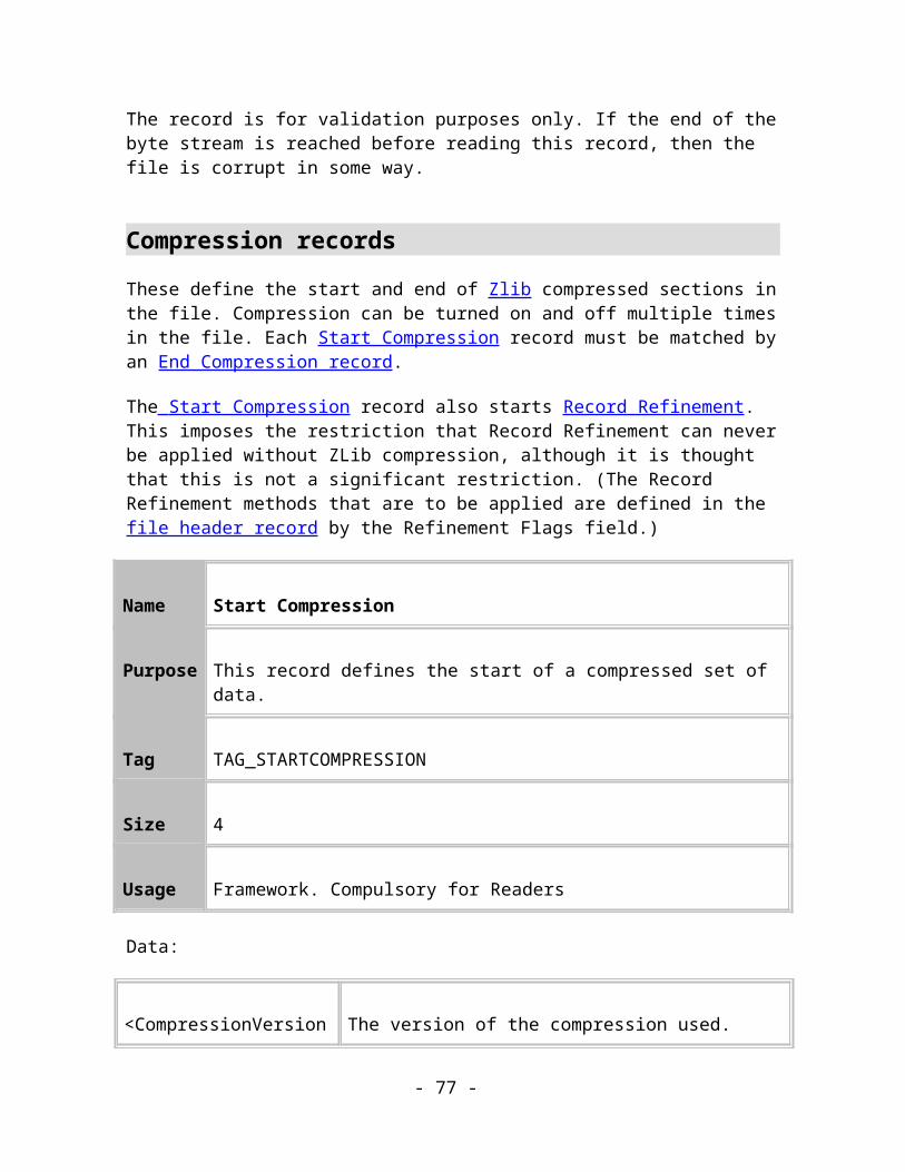
must render an outline. A closed path (a “shape” in Xtreme terminology) is always stored as a TAG_PATH_FILLED_STROKED and an open path (a “line” in Xtreme) is stored as a TAG_PATH_STROKED. If a path object should not have an outline or a fill then it should have a relevant “no color” attribute applied rather than be stored as one of the other record variants. The other variants are intended only for special purposes where the path in question should not be rendered.
Name Path Flags
Purpose This record describes the flags associated with the next path in the file
Tag TAG_PATH_FLAGS
Size Variable
Usage Image, Not required in web files (recommended for editors)
Data:
<Flags List> A list of flags
<Flags List> ::= <Flags : BYTE>+
Flags := <IsSmooth : BIT(0)> <IsRotate : BIT(1)> <IsEndPoint: BIT(2)>
IsSmooth: Set when the two Bezier control points on either side of this point must be recalculated if the point is edited.
IsRotate: Set to tell the Bezier editing software that if the opposite control point is edited, this control point will rotate to keep the curve smooth.
IsEndPoint: Set for every point that isn’t a Bezier control point, including Moveto and Lineto points.
All other flags are 0 and are reserved for future use.
- 77 -
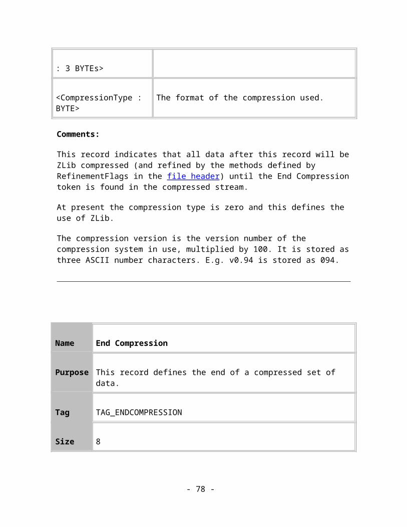
Comments:
This contains a list of flags bytes defining the flags associated with each co-ordinate in the next path record in the file. The number of entries is implied by the size of the record.
Path Refinement
The Record Refinement stage of Xar file compression operates on Path records to make them more “digestible” by the Zlib compression stage. It does this by altering the way in which the co-ordinates are stored in the Points array so that there are longer runs of similar bytes which Zlib can detect and compress more frequently.
Figure 8.1. How record data is compressed and decompressed.
The above diagram shows how the Record Refiner sits between the normal record stream and the Zlib compression system.
Relative Path Co-ordinates
The co-ordinates in a path can contain arbitrary values which are unlikely to be similar or to contain long runs of similar bytes. This means that the Zlib compression stage is unlikely to be able to compress them efficiently.
The Record refiner deals with this by storing each co-ordinate as relative to the previous one. For most paths, relative storage will result in the top two bytes of each ordinate to be
- 78 -
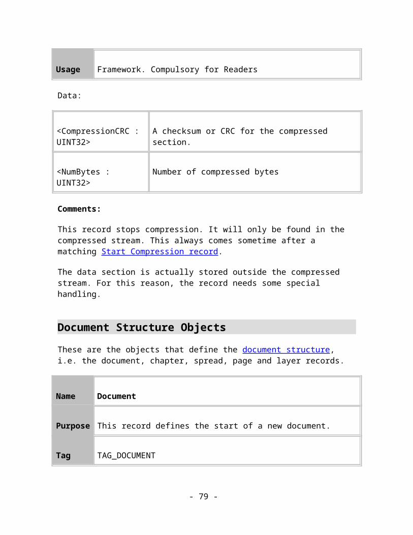
either 0x0000 or 0xFFFF. These common sequences should result in higher compression, compared with compressing a list of arbitrary absolute co-ordinates, which would typically only have the top byte that is common.
All co-ordinates of a path, except for the first co-ordinate, will be converted to relative values. The first co-ordinate is absolute and defines the starting point. The next is the relative distance from the next absolute co-ordinate to the previous absolute co-ordinate.
Here’s an example:
Verbs Absolute Coords Relative Coords
PT_MOVETO (X1,Y1) (X1,Y1) – first coord is always absolute
PT_BEZIERTO (X2,Y2) (X1-X2,Y1-Y2)
PT_BEZIERTO (X3,Y3) (X2-X3,Y2-Y3)
PT_BEZIERTO (X4,Y4) (X3-X4,Y3-Y4)
PT_LINETO (X5,Y5) (X4-X5,Y4-Y5)
A further change is made to the co-ordinates by interleaving the X and Y ordinates. This has the effect of producing long runs of 0x0 and 0xFF bytes which Zlib can detect and compress efficiently.
The relative co-ordinate is stored most-significant bytes first unlike other multi-byte values. E.g. the relative co-ordinate (0x11223344, 0xAABBCCDD) will be stored as the following stream of bytes:
0x11, 0xAA, 0x22, 0xBB, 0x33, 0xCC, 0x44, 0xDD
Name Relative Path
- 79 -

Purpose This record represents a refined path object.
Tag TAG_PATH_RELATIVE,TAG_PATH_RELATIVE_FILLED,TAG_PATH_RELATIVE_STROKED,TAG_PATH_RELATIVE_FILLED_STROKED
Size Variable
Usage Image, Compulsory
Data :
<Verb and Coord List> A list of all the Verbs and co-ordinates in the path.
<Verb and Coord List> ::= (<Verb : BYTE> <COORD>)+
(NOTE: These are refined coordinates as described above)
Comments:
This record is the refined version of the TAG_PATH record. Its general layout is identical to that of TAG_PATH except that the co-ordinates and verbs are stored differently as explained in the Path Refinement section above and the number of entries is implied by the size of the record (9 bytes per entry). See Paths for more information.
Similar Paths
Documents often contain similar paths: duplicate paths may be located in different positions or a path may be copied and then undergo some distortion, such as being scaled. Similar transformations can also be achieved by “Cloning”. In any case, the similar paths can be described as transformations of the original path. These transformations are most easily described using matrices and linear algebra.
- 80 -
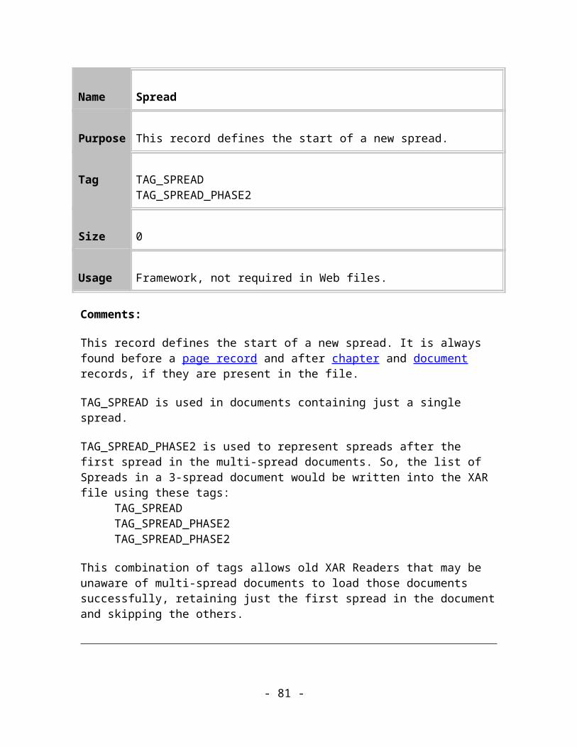
Name Transformed Path
Purpose This record represents a refined path object.
Tag TAG_PATHREF_TRANSFORM
Size 28
Usage Image. Optional
Data :
<Path Reference : REF> The sequence number of the path to transform.
<Transformation : MATRIX> The matrix to apply to the referenced path.
<MATRIX> ::= <a : FIXED16> <b : FIXED16> <c : FIXED16> <d : FIXED16> <e : INT32> <f : INT32>
Comments:
MATRIX is an abbreviated 3 x 3 matrix with other elements zero and one as is consistent with homogeneous co-ordinates. To transform a point (x,y) in the reference path to the corresponding point in the similar path (s,t), apply the following calculations,
s = ax + cy + e
t = bx + dy + f
Thus by transforming each point in the reference path the new path is obtained.
NOTE: This record is inherently “lossy” due to the limited accuracy obtainable from the FIXED16 elements when transforming the reference path. A trade-off between space and accuracy is possible: by allowing greater flexibility in what constitutes a similar path, more paths can be represented using this record and occupy less space in the data stream.
- 81 -
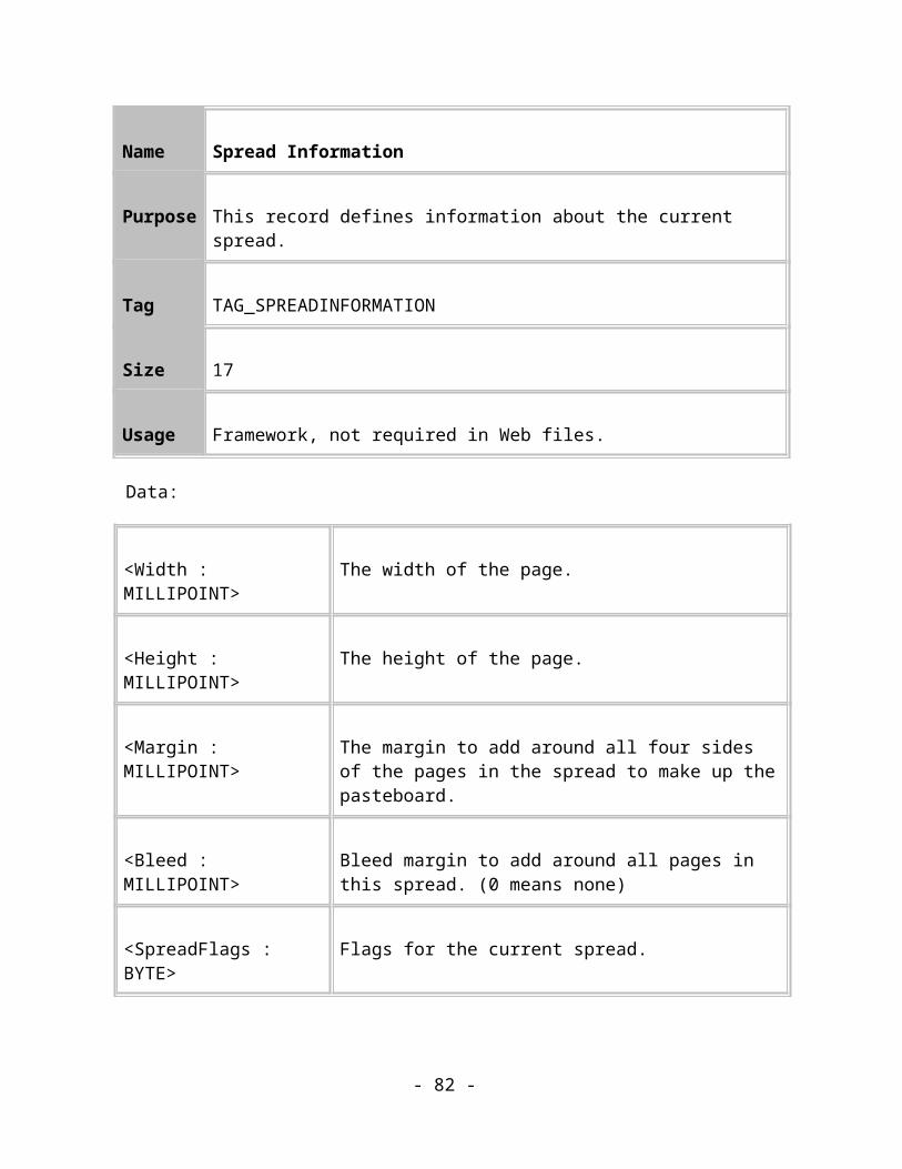
AttributesThis section defines all the general attribute records. Text-specific attributes are defined in the Text chapter.
Fills
The Xar format supports 11 basic types, or geometries of solid and graduated colour fill styles. The simplest is a solid (flat) fill colour. The 10 other varieties of more complex graduated colour fills:
Linear, and linear multi-stage, Circular, and circular multi-stage
Elliptical and elliptical multi-stage
Conical and Conical multi-stage
Bitmap, and Contone bitmap
Fractal clouds
Fractal Noise
3 colour graduated
4 colour graduated
Diamond multi-stage fill
In addition to the fill style, the fill tiling can be defined, which controls whether the fill repeats.
Finally for the graduated colours fills there is an addition fill effect which controls the manner in which colours fade form one to another. The 3 options are fade, rainbow and alt rainbow. The normal fade, just is a direct fade from one colour to another (it’s not always a linear fade as it can be altered by a profile (link to profiles page). Rainbow and Alt-rainbow take a tour through the spectrum of colors from the start colour to the end colour.
These records define the attributes that can be applied as fills to objects in the tree. This first section covers simple and graduated fills.
- 82 -

See Appendix B for a list of the default values for these attributes.
Name Flat Fill Colour
Purpose This record sets the current fill to a flat fill of the specified colour.
Tag TAG_FLATFILL
Size 4
Usage Image. Compulsory
Data:
< Colour : COLOURREF > A reference to a colour.
Comments:
This record sets the current fill to a flat fill of the specified colour.
Name Standard Fill Colours
Purpose These records set the current fill to be none, uniform black or uniform white.
Tag TAG_FLATFILL_NONETAG_FLATFILL_BLACKTAG_FLATFILL_WHITE
Size 0
- 83 -

Usage Image. Compulsory
Comments:
TAG_FLATFILL_NONE
This record sets the current fill to be “none” – in other words it instructs objects not to be filled with anything. Any closed objects that exist in the scope of this attribute will be “hollow”.
TAG_FLATFILL_BLACK
This record sets the current fill to be black, RGB(0,0,0). It is defined as a separate record from TAG_FLATFILL because it’s so common.
TAG_FLATFILL_WHITE
This record sets the current fill to be white, RGB(0xFF,0xFF,0xFF). It is defined as a separate record from TAG_FLATFILL because it’s so common.
Name Linear Graduated Fill
Purpose This record sets the current fill to be a linear fill.
Tag TAG_LINEARFILLTAG_ LINEARFILL3POINT
Size 40 (24)48 (32)
Usage Image. Compulsory.
Data:
- 84 -

< Start Point : COORD > The point that the linear fill will start from
< End Point : COORD > The point that the linear fill will end at
< End Point 2 : COORD > The other point that controls the shear of the fill (only present in 3 point variant)
< Start Colour : COLOURREF > A reference to the colour to use at the start point
< End Colour : COLOURREF > A reference to the colour to use at the end point
< FillProfile : PROFILE > The profile applied to the fillNote: this item may not be present in older Xar format documents
Comments:
The direction of a linear fill is actually controlled by the position of the second end point. In the first type of record with only two points, the second end point is at right angles to the supplied end point. The second type of record allows the definition of fills that are not perpendicular to the line joining the start and end points. The diagram below shows two linear fills, the first is a two point one where the third point is implied and the second is a three point one where the third point specifies that the fill is sheared.
Figure 9.1. Linear fills.
- 85 -

Name Linear Multistage Fill
Purpose This record sets the current fill to be a linear, multistage fill.
Tag TAG_LINEARFILLMULTISTAGETAG_LINEARFILLMULTISTAGE3POINT
Size Variable
Usage Image. Compulsory.
Data:
< Start Point : COORD > The point that the linear fill will start from
< End Point : COORD > The point that the linear fill will end at
< End Point 2 : COORD > The other point that controls the shear of the fill (only present in 3 point variant)
< Start Colour : COLOURREF > A reference to the colour to use at the start point
< End Colour : COLOURREF > A reference to the colour to use at the end point
< NumCols : UINT32 > The number of extra colours in this fill. The following Position and Colour elements are repeated for each extra colour
< Position : DOUBLE > The “position” of this colour. This value is between 0.0 and 1.0 indicating the start and end of the fill
- 86 -

< Colour : COLOURREF > A reference to the colour to use at this point
Name Circular Graduated fill
Purpose This record sets the current fill to be a circular fill.
Tag TAG_CIRCULARFILL
Size 40 (24)
Usage Image. Compulsory.
Data:
< Centre Point : COORD > The centre of the circle that the fill will radiate from
< Edge Point : COORD > A point that lies at the edge of the circle.
< Start Colour : COLOURREF > A reference to the colour to use at the centre
< End Colour : COLOURREF > A reference to the colour to use at the edge
< FillProfile : PROFILE > The profile applied to the fillNote: this item may not be present in older Xar format documents
Comments:
- 87 -

Here is an example of a circular fill:
Figure 9.2. A circular fill.
Name Circular Multistage fill
Purpose This record sets the current fill to be a circular multistage fill.
Tag TAG_CIRCULARFILLMULTISTAGE
Size Variable
Usage Image. Compulsory.
Data:
< Centre Point : COORD > The centre of the circle that the fill will radiate from
< Edge Point : COORD > A point that lies at the edge of the circle.
< Start Colour : COLOURREF > A reference to the colour to use at the centre
- 88 -

< End Colour : COLOURREF > A reference to the colour to use at the edge
< NumCols : UINT32 > The number of extra colours in this fill. The following Position and Colour elements are repeated for each extra colour
< Position : DOUBLE > The “position” of this colour. This value is between 0.0 and 1.0 indicating the start and end of the fill
< Colour : COLOURREF > A reference to the colour to use at this point
Name Elliptical Graduated fill
Purpose This record sets the current fill to be a elliptical fill.
Tag TAG_ELLIPTICALFILL
Size 48 (32)
Usage Image. Compulsory.
Data:
< CentrePoint : COORD > The position of the centre that the fill will radiate from.
< MajorAxes : COORD > The position of the major axis point.
- 89 -

< MinorAxes : COORD > The position of the minor axis point.
< Start Colour : COLOURREF > A reference to the colour to use at the centre
< End Colour : COLOURREF > A reference to the colour to use at the edge
< FillProfile : PROFILE > The profile applied to the fillNote: this item may not be present in older Xar format documents
Comment:
Here are two elliptical fills, the first has the control points at right angles and the second has been sheared:
Figure 9.3. Elliptical fills.
Name Elliptical Multistage fill
Purpose This record sets the current fill to be a elliptical multistage fill.
Tag TAG_ELLIPTICALFILLMULTISTAGE
- 90 -

Size Variable
Usage Image. Compulsory.
Data:
< CentrePoint : COORD > The position of the centre that the fill will radiate from.
< MajorAxes : COORD > The position of the major axis point.
< MinorAxes : COORD > The position of the minor axis point.
< Start Colour : COLOURREF > A reference to the colour to use at the centre
< End Colour : COLOURREF > A reference to the colour to use at the edge
< NumCols : UINT32 > The number of extra colours in this fill. The following Position and Colour elements are repeated for each extra colour
< Position : DOUBLE > The “position” of this colour. This value is between 0.0 and 1.0 indicating the start and end of the fill
< Colour : COLOURREF > A reference to the colour to use at this point
Name Conical Graduated fill
- 91 -

Purpose This record sets the current fill to be a conical fill.
Tag TAG_CONICALFILL
Size 40 (24)
Usage Image. Compulsory.
Data:
< Centre Point : COORD > The centre of the cone that the fill will radiate from
< Edge Point : COORD > A point that lies at the edge of the cone.
< Start Colour : COLOURREF > A reference to the colour to use at the centre
< End Colour : COLOURREF > A reference to the colour to use at the edge
< FillProfile : PROFILE > The profile applied to the fillNote: this item may not be present in older Xar format documents
Comment:
Here’s a conical fill:
- 92 -

Figure 9.4. A conical fill.
Name Conical Multistage fill
Purpose This record sets the current fill to be a conical multistage fill.
Tag TAG_CONICALFILLMULTISTAGE
Size Variable
Usage Image. Compulsory.
Data:
< Centre Point : COORD > The centre of the cone that the fill will radiate from
< Edge Point : COORD > A point that lies at the edge of the cone.
< Start Colour : COLOURREF > A reference to the colour to use at the centre
- 93 -
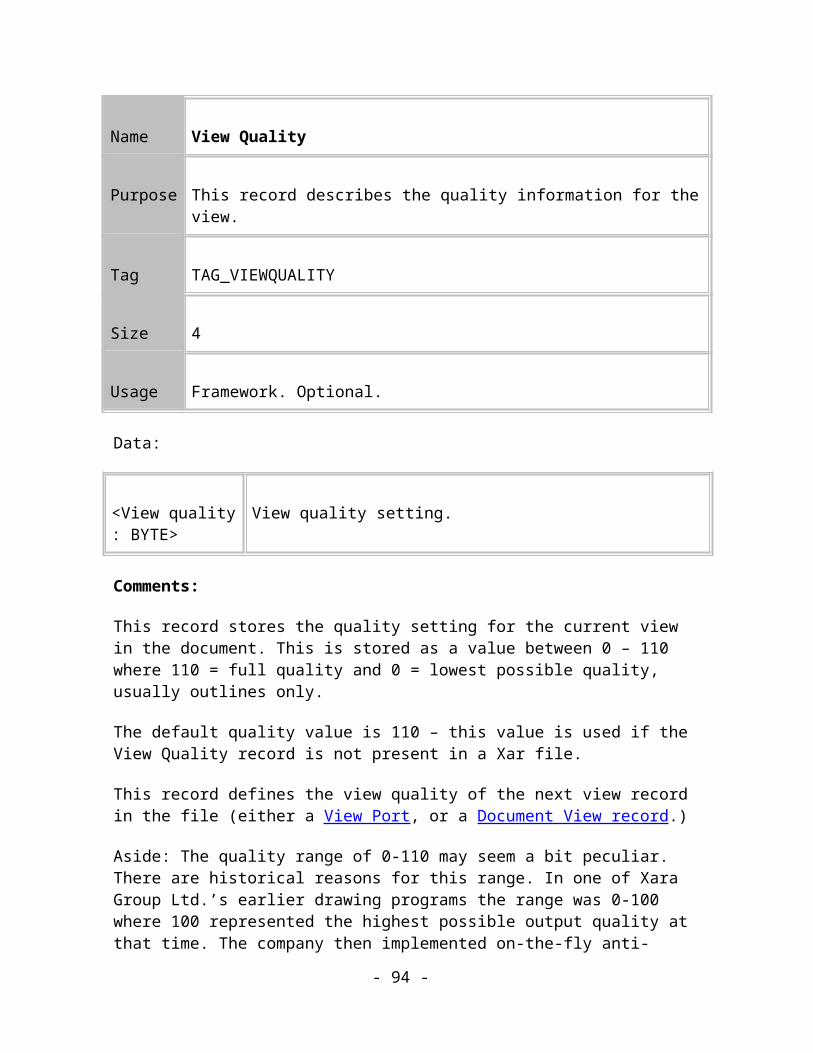
< End Colour : COLOURREF > A reference to the colour to use at the edge
< NumCols : UINT32 > The number of extra colours in this fill. The following Position and Colour elements are repeated for each extra colour
< Position : DOUBLE > The “position” of this colour. This value is between 0.0 and 1.0 indicating the start and end of the fill
< Colour : COLOURREF > A reference to the colour to use at this point
Name Bitmap Fill
Purpose This record sets the current fill type to be a bitmap fill.
Tag TAG_BITMAPFILL
Size 44 (28)
Usage Image. Compulsory.
Data:
< BottomLeft : COORD > The position of the bottom left hand corner of the parallelogram.
< BottomRight : COORD > The position of the bottom right hand corner of the parallelogram.
- 94 -

< TopLeft : COORD > The position of the top left hand corner of the parallelogram.
< Bitmap : BITMAPREF> The bitmap reference to use as the fill.
< FillProfile : PROFILE > The profile applied to the fillNote: this item may not be present in older Xar format documents
Comments:
This record sets the current fill to be a bitmap fill. This fill applies a bitmap to the object using the control points to define how the fill is transformed and positioned. The control points define a parallelogram by the bottom left, top left and bottom right points and the bitmap is then plotted inside this parallelogram.
The fill can be non-repeating, repeating or inverted-repeating.When not repeating, the filled area does not extend beyond the parallelogram defined in the record.When repeating, the entire shape is filled by tessellated parallelograms.When inverted-repeating, the bitmap is flipped over so that one corner is near the equivalent corners of the three other parallelograms touching it before being fitted into the tessellated parallelograms. This often makes the join between parallelograms less visible.These features are controlled by a separate attribute records, TAG_FILL_REPEATING, TAG_FILL_NONREPEATING and TAG_FILL_REPEATINGINVERTED.
Here are two bitmap fills, one non-repeating with a slight rotation and the other repeating with a more complex transformation:
Figure 9.5. Bitmap fills.
- 95 -

Name Contone Bitmap Fill
Purpose This record describes a contone bitmap fill.
Tag TAG_CONTONEBITMAPFILL
Size 52 (36)
Usage Image. Compulsory.
Data:
< BottomLeft : COORD > The position of the bottom left hand corner of the parallelogram.
< BottomRight : COORD > The position of the bottom right hand corner of the parallelogram.
< TopLeft : COORD > The position of the top left hand corner of the parallelogram.
< Start colour : COLOURREF > A reference to the colour to use at the centre.
< End colour : COLOURREF > A reference to the colour to use at the edge.
< Bitmap : BITMAPREF> The bitmap reference to use as the fill.
< FillProfile : PROFILE > The profile applied to the fillNote: this item may not be present in older Xar format documents
- 96 -
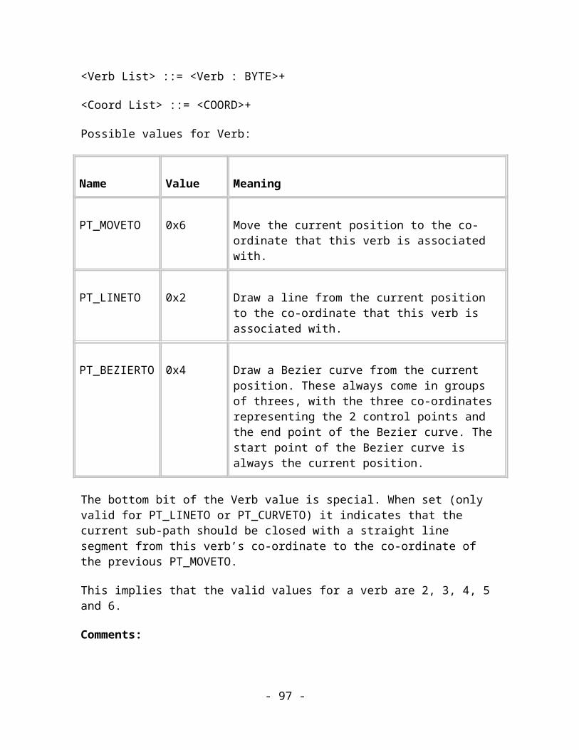
Comments:
This specifies a fill type that is very similar to the standard bitmap fill described above. The only difference is that two colours are specified, defining a contone (“continuous tone”) onto which the intensities of the bitmap are mapped. This is used to restrict the colours of a displayed bitmap fill.
The colours allows a greyscale bitmap’s palette to be overridden and plotted such that the black and white end colours are plotted using the start and end colours. The grey levels between black and white are generated by computing the appropriate mix between the start and end contone colours. If the bitmap is not greyscale then the colour intensities are used to pick new colours from the contone.
The fill can be non-repeating, repeating or inverted-repeating.When not repeating, the filled area does not extend beyond the parallelogram defined in the record.When repeating, the entire shape is filled by tessellated parallelograms.When inverted-repeating, the bitmap is flipped over so that one corner is near the equivalent corners of the three other parallelograms touching it before being fitted into the tessellated parallelograms. This often makes the join between parallelograms less visible.These features are controlled by a separate attribute records, TAG_FILL_REPEATING, TAG_FILL_NONREPEATING and TAG_FILL_REPEATINGINVERTED.
Here are two contone bitmap fills (it’s the contoned version of figure 9.5):
Figure 9.6. Contoned bitmap fills where the contone is from blue to white.
Name Fractal Clouds Fill
Purpose This record describes a fractal clouds fill.
- 97 -
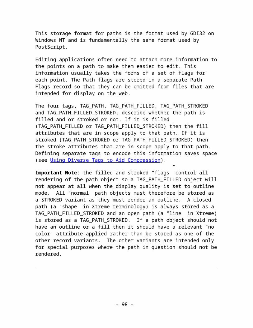
Tag TAG_FRACTALFILL
Size 69 (53)
Usage Image. Compulsory.
Data:
< BottomLeft : COORD > The position of the bottom left hand corner of the parallelogram.
< BottomRight : COORD > The position of the bottom right hand corner of the parallelogram.
< TopLeft : COORD > The position of the top left hand corner of the parallelogram.
< Start colour : COLOURREF > A reference to the colour to use at the centre.
< End colour : COLOURREF > A reference to the colour to use at the edge.
< Seed : INT32 > The seed applied to the fractal fill.
< Graininess : FIXED16 > The graininess of the fractal fill.
< Gravity : FIXED16 > The gravity to apply to the fill.
< Squash : FIXED16 > The squash to apply to the fill.
< Resolution : UINT32 > The resolution of this fill (DPI).
- 98 -
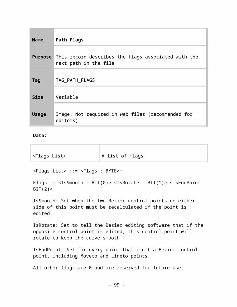
< Tileable : BYTE > Flag to say if tileable or not.
< FillProfile : PROFILE > The profile applied to the fillNote: this item may not be present in older Xar format documents
Comments:
This record sets the current fill to be a fractal cloud fill. This record describes a fractal fill and all the required parameters to be able to regenerate the fractal pattern when the fill is loaded. This fractal is regenerated as a bitmap and then applied to the object using the control points in the same way that they are used for bitmap fills. The control points define a parallelogram by the bottom left, top left and bottom right points and the bitmap is then plotted inside this parallelogram.
The fill can be non-repeating, repeating or inverted-repeating.When not repeating, the filled area does not extend beyond the parallelogram defined in the record.When repeating, the entire shape is filled by tessellated parallelograms.When inverted-repeating, the bitmap is flipped over so that one corner is near the equivalent corners of the three other parallelograms touching it before being fitted into the tessellated parallelograms. This often makes the join between parallelograms less visible.These features are controlled by a separate attribute records, TAG_FILL_REPEATING, TAG_FILL_NONREPEATING and TAG_FILL_REPEATINGINVERTED.
The fractal is generated as a greyscale bitmap but then is plotted using the defined start and end colours.
Here are two fractal clouds fills:
Figure 9.7. Fractal clouds fills.
- 99 -

Name Fractal Noise Fill
Purpose This record describes a fractal noise (plasma) fill.
Tag TAG_NOISEFILL
Size 61
Usage Image. Compulsory.
Data:
< BottomLeft : COORD > The position of the bottom left hand corner of the parallelogram.
< BottomRight : COORD > The position of the bottom right hand corner of the parallelogram.
< TopLeft : COORD > The position of the top left hand corner of the parallelogram.
< Start colour : COLOURREF > A reference to the colour to use at the centre.
< End colour : COLOURREF > A reference to the colour to use at the edge.
< Graininess : FIXED16 > The graininess of the fractal fill.
< Seed : INT32 > The seed applied to the fractal fill.
- 100 -

< Resolution : UINT32 > The resolution of this fill (DPI).
< Tileable : BYTE > Flag to say if tileable or not.
< FillProfile : PROFILE > The profile applied to the fillNote: this item may not be present in older Xar format documents
Comments:
This record sets the current fill to be a fractal plasma fill. This record describes a fractal fill and all the required parameters to be able to regenerate the fractal pattern when the fill is loaded. This fractal is regenerated as a bitmap and then applied to the object using the control points in the same way that they are used for bitmap fills. The control points define a parallelogram by the bottom left, top left and bottom right points and the bitmap is then plotted inside this parallelogram.
The fill can be non-repeating, repeating or inverted-repeating.When not repeating, the filled area does not extend beyond the parallelogram defined in the record.When repeating, the entire shape is filled by tessellated parallelograms.When inverted-repeating, the bitmap is flipped over so that one corner is near the equivalent corners of the three other parallelograms touching it before being fitted into the tessellated parallelograms. This often makes the join between parallelograms less visible.These features are controlled by a separate attribute records, TAG_FILL_REPEATING, TAG_FILL_NONREPEATING and TAG_FILL_REPEATINGINVERTED.
The fractal is generated as a greyscale bitmap but then is plotted using the defined start and end colours.
Here are two fractal plasma fills:
- 101 -

Figure 9.7. Fractal plasma fills.
Name Three-colour Graduated Fill
Purpose This record sets the current fill to be a three-colour fill.
Tag TAG_THREECOLFILL
Size 36
Usage Image. Compulsory.
Data:
< Point1 : COORD > The co-ordinate of Colour1.
< Point2 : COORD > The co-ordinate of Colour2.
< Point3 : COORD > The co-ordinate of Colour3.
< Colour1 : COLOURREF > A reference to the colour to use at Point1.
< Colour2 : COLOURREF > A reference to the colour to use at Point2.
< Colour3 : COLOURREF > A reference to the colour to use at Point3.
Comments:
Here’s an example three-colour fill:
- 102 -
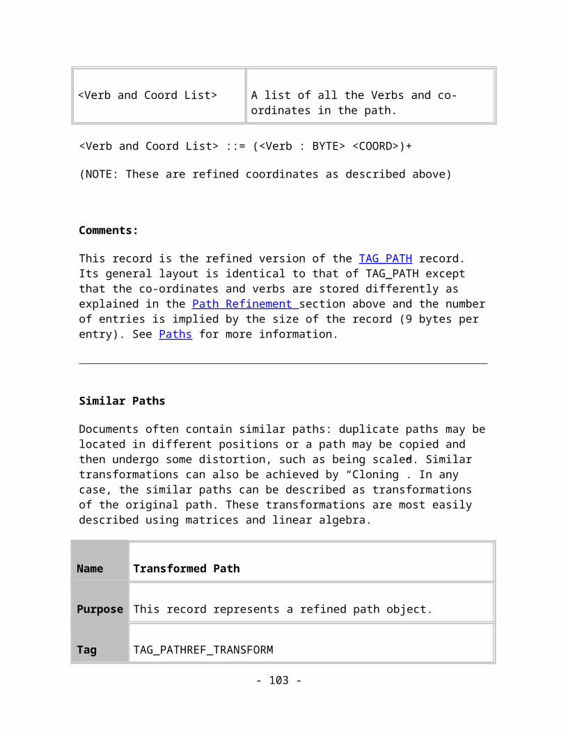
Figure 9.8. A three-colour fill.
Name Four-colour Graduated Fill
Purpose This record sets the current fill to be a four-colour fill.
Tag TAG_FOURCOLFILL
Size 40
Usage Image. Compulsory.
Data:
< Point1 : COORD > The co-ordinate of Colour1.
< Point2 : COORD > The co-ordinate of Colour2.
< Point3 : COORD > The co-ordinate of Colour3.
< Colour1 : COLOURREF > A reference to the colour to use at Point1.
- 103 -

< Colour2 : COLOURREF > A reference to the colour to use at Point2.
< Colour3 : COLOURREF > A reference to the colour to use at Point3.
< Colour4 : COLOURREF > A reference to the colour to use at the implied Point4.
Comments:
The three points define a parallelogram – in a similar way to the bitmap fill record. Thus, the fourth point is implied and can be computed given the other three points.
Here’s an example four-colour fill:
Figure 9.9. A four-colour fill.
Name Diamond Graduated Fill
Purpose This record sets the current fill to be a diamond fill.
Tag TAG_SQUAREFILL
Size 48 (32)
- 104 -

Usage Image. Compulsory.
Data:
< Centre Point : COORD > The co-ordinate of the centre of the diamond.
< Right Point : COORD > The co-ordinate of the middle of the right edge of the diamond.
< Top Point : COORD > The co-ordinate of the middle of the top edge of the diamond.
< Colour1 : COLOURREF > A reference to the colour to use at the centre of the diamond.
< Colour2 : COLOURREF > A reference to the colour to use at the edges of the diamond.
< FillProfile : PROFILE > The profile applied to the fillNote: this item may not be present in older Xar format documents
Comments:
Here are two example diamond fills:
Figure 9.10. A diamond fill.
- 105 -

Name Diamond Multistage Fill
Purpose This record sets the current fill to be a diamond multistage fill.
Tag TAG_SQUAREFILLMULTISTAGE
Size Variable
Usage Image. Compulsory.
Data:
< Centre Point : COORD > The co-ordinate of the centre of the diamond.
< Right Point : COORD > The co-ordinate of the middle of the right edge of the diamond.
< Top Point : COORD > The co-ordinate of the middle of the top edge of the diamond.
< Colour1 : COLOURREF > A reference to the colour to use at the centre of the diamond.
< Colour2 : COLOURREF > A reference to the colour to use at the edges of the diamond.
< NumCols : UINT32 > The number of extra colours in this fill. The following Position and Colour elements are repeated for each extra colour
- 106 -

< Position : DOUBLE > The “position” of this colour. This value is between 0.0 and 1.0 indicating the start and end of the fill
< Colour : COLOURREF > A reference to the colour to use at this point
Fill Effects
Fill effects defines how one colour is transformed into another colour in all of the basic fill types described above. The current fill effect applies to any of the fills that contain two colours, defining which colours are rendered between the start and end colours. (Three and four colour fills always use the “Fade” fill effect.)
There are three fill effects: Fade, Rainbow and Alternative Rainbow.
Name Fill Effects
Purpose Determine how one colour is transformed into another in all two-colour fills.
Tag TAG_FILLEFFECT_FADE,TAG_FILLEFFECT_RAINBOW,TAG_FILLEFFECT_ALTRAINBOW
Size 0
Usage Image. Compulsory.
Comment:
TAG_FILLEFFECT_FADE: Transform the start colour into the end colour by taking the shortest route between the 2 colours, in RGB colour space.
TAG_FILLEFFECT_RAINBOW: Transform the start colour into the end colour by taking the shortest route in the H dimension of the HSV colour space.
- 107 -

TAG_FILLEFFECT_ALTRAINBOW: Transform the start colour into the end colour by taking the longest route in the H dimension of the HSV colour space.
Figure 9.11. The three fill effects on a red to green linear fill: Left-to-right, Fade, Rainbow and Alternative Rainbow.
Fill Repeat Methods
Fill repeat methods apply to all of the fill types except flat and conical. Not all of the repeat types apply to all of the fills.
The fill repeat records are:
Name Fill Repeating
Purpose Determines how the fill is tessellated.
Tag TAG_FILL_REPEATING,TAG_FILL_NONREPEATING,TAG_FILL_REPEATINGINVERTED,TAG_FILL_REPEATING_EXTRA
Size 0
Usage Image. Compulsory.
Comments:
TAG_FILL_REPEATING: The fill is repeated throughout the object, i.e. it is tessellated continuously. This can apply to bitmap, fractal, 3-colour and 4-colour fills.TAG_FILL_NONREPEATING: The fill is not repeated at all, and thus might not cover the
- 108 -
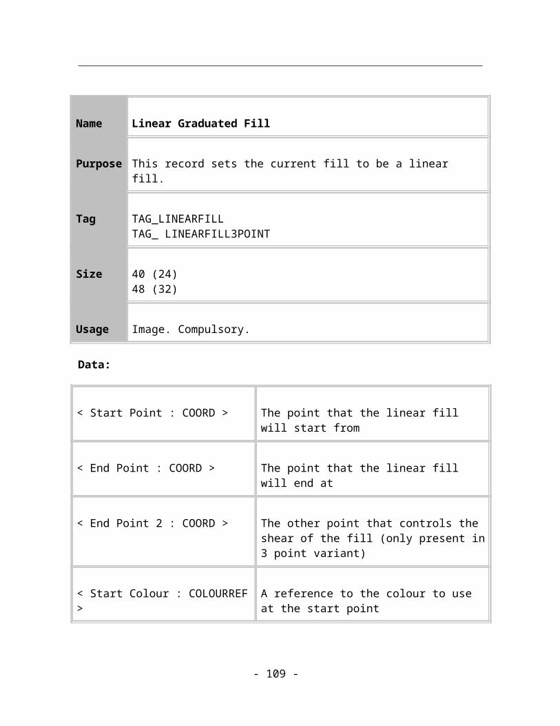
whole shape that it is applied to. This can apply to all fill types.TAG_FILL_INVERTEDREPEATING: The fill is repeatedly tessellated, except that each time it is repeated, the bitmap is inverted so that one of its corners touches the equivalent corner on the three other bitmaps touching it. This can apply to bitmap and fractal fills.TAG_FILL_REPEATING_EXTRA: The fill is repeated with the start point being the start colour and a point half-way through the fill being the end colour. The fill then fades back to the start colour at the end point and then repeats indefinitely. This can apply to linear, circular, elliptical and diamond fills.
If a fill has an unsupported repeat type (e.g. a linear fill with a TAG_FILL_REPEATING) then it is rendered as non-repeating.
Transparency attributes
The transparency attributes are very similar to the fill attributes described above. In fact, for every type of colour fill there is an equivalent transparency “fill” which has similar geometric properties. The main difference between a fill attribute and a transparency attribute is that, where the fill attribute controls the colour of a filled shape, the transparency attribute controls the opacity of the shape – how much of the image beneath it can be seen through the shape.
It is important to understand that for any object in a Xar file, it can contain both a fill attribute and separate transparency attribute. The geometry of the transparency is independent of the geometry of the fill style.
This is an example of a simple shape with a horizontal linear graduated fill and a vertical linear graduated transparency. Note that the start and end points of the graduated fill (or transparency) can be outside the bounds of the object being filled.
There are 11 styles or geometries of the transparency (referred to in Xara X as transparency shapes). These are a similar set of fill geometries listed above: Flat, linear, circular, elliptical, conical, diamond, three point, 4 point, bitmap, and two types of fractal transparency.
- 109 -

In addition the method by which the transparency effect is composited on the page (i.e. combined with the colours below) is determined by one of 10 possible transparency types. This is sometimes referred to in other programs as a blending mode. The transparency types supported are (in our terminology); mix, stain, bleach, contrast, saturation, darken, lighten, brightness, luminosity and hue.
Finally, as with graduated colour fills, there are tiling modes that control how the geometry repeats, which can be a simple, ‘one-off’ graduated fill, or a repeating style.
This is a more complex example of an ellipse combining graduated fill attribute of one style and a different graduated transparency attribute.
Transparency Type
The transparency records all have a field called Transparency Type. This defines the composition or blending model used to combine the colours of the object underneath with this object. The ‘mix’ transparency is the most common type and the equivalent of the common form of transparency as defined by most applications that support transparency or translucency.
Transparency Type ::= < Transparency Type Value : BYTE >
The allowable values for the transparency type are described in the following table. The background colour is represented by lower case letters and the colour of the object being rendered is represented by upper case letters. The formulae are applied three times, once for each of the R, G and B components. The component value is represented by the letter C (or c). The transparency value is represented by T. Some of the formulae use the greyscale intensity of the colour represented by U (or u) where U = (77R + 151G + 28B) / 256
- 110 -

Transparency Type
Description Formula
0 – None Transparency is not used, i.e. the current fill is completely opaque.
C = C
1 – Mix Gives the effect of mixing the colour of the transparent object with the colours underneath it, like mixing two paints in a pot.
C = Tc + (1-T)C
2 – Stained glass Gives the impression that the transparent object is made of coloured stained glass overlaying the colours underneath.
C = c(C+(1-T)C)
3 – Bleach Gives the effect that the objects underneath the transparent object are having the colours bleached out of them.
C = Tc+(1-T)(C+c-Cc)
4 – Contrast Changes the contrast of underlying objects.
C = c(T+2U-2TU) when U < 0.5c = Tc+(1-T)Uc when U >= 0.5
5 – Saturation Changes the saturation of underlying objects.
C = u+(c-u)(T+2U(1-T)) for U < 0.5c = u+(c-u)(T+U(2U+1)(1-T)) for U >= 0.5
6 – Darken This is a greyscale version of the Stained glass type.
C = c(U+(1-T)U)
7 – Lighten This is a greyscale version of C = (1-T)U+c(1-(1-T)U)
- 111 -
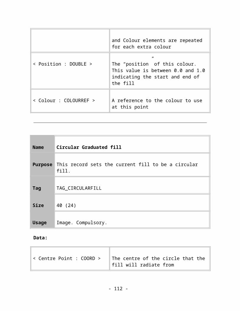
the Bleach type.
8 – Brightness Makes the colours of underlying objects lighter or darker.
C = c(T+2U-2TU) for U < 0.5c = (1-T)(2U-1)+c(1-(1-T)(2U-1)) for U >= 0.5
9 – Luminosity This uses the 112ezier112l112 equivalent of the color to control the luminosity (or Value) of underlying objects.
C = c(T+(1-T)U/max(r,g,b))
10 – Hue This shifts the hue of underlying objects toward the hue of this object.
C = c+SaturationI(1-T)(RGB[ HSV(HueI,SaturationI,ValueI) ]-c)
When rendering to a 32 bit RGBA bitmap the formulae are different. M = (R+G+B)/3
Transparency Type
Description Formula
0 – None Transparency is not used, i.e. the current fill is completely opaque.
C = Ct = 0
1 – Mix Gives the effect of mixing the colour of the transparent object with the colours underneath it, like mixing two paints in a pot.
C = Tc + (1-T)Ct = Tt
2 – Stained glass Gives the impression that the transparent object is made of coloured stained glass overlaying the colours underneath.
C = c(T+C-TC)+t(T+C-TC)/2-t(T+M-TM)/2t = (T+M-TM)t
- 112 -
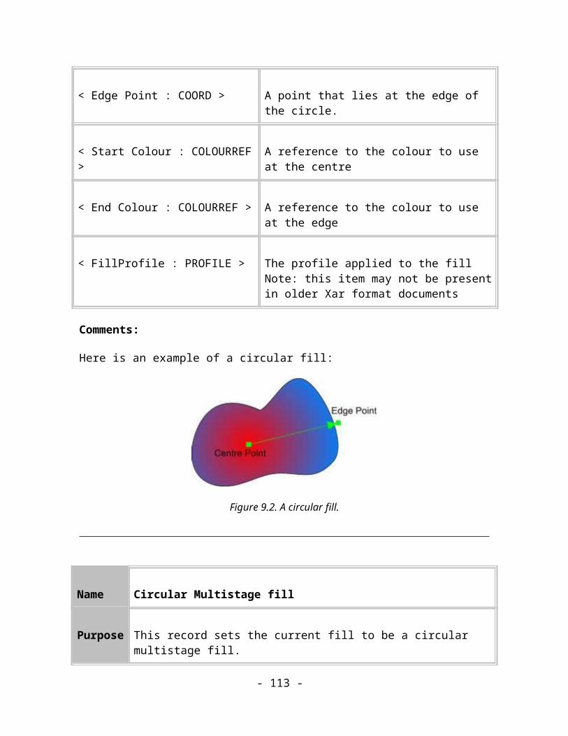
3 – Bleach Gives the effect that the objects underneath the transparent object are having the colours bleached out of them.
C = 1-(1-c)(1-C+TC)+t(1-C+TC)/2-t(1-M+TM)/2t = (1-M+TM)t
4 – Contrast Changes the contrast of underlying objects.
C = ½+(c-1/2)(T+2U-2UT)t = (T+2U-2UT)t for U < 0.5c = Tc+(1-T)L[U,c/(1-t)](1-t)t = t for U >= 0.5
5 – Saturation Changes the saturation of underlying objects.
C = u+(c-u)(T+2U(1-T))t = t for U < 0.5c = u+(c-u)(T+U(2U+1)(1-T))t = t for U >= 0.5
6 – Darken This is a greyscale version of the Stained glass type.
C = c(T+U-TU)t = (T+U-TU)t
7 – Lighten This is a greyscale version of the Bleach type.
C = c(1-U+TU)+(U-TU)t = (1-U+UT)t
8 – Brightness Makes the colours of underlying objects lighter or darker.
C = c = c(T+2U-2TU)t = (T+2U-2TU)t for U < 0.5c = (1-T)(2U-1)+c(1-(1-T)(2U-1))t = (1-(1-T)(2U-1))t for U >= 0.5
9 – Luminosity This uses the 113ezier113l113 equivalent of the color to control the luminosity (or Value) of underlying objects.
C = c(T+(1-T)(1-t)U/max(r,g,b))t = t
10 – Hue This shifts the hue of underlying objects toward the hue of this object.
C = c + (1-t)Sat(C)(1-T)(RGB[ HSV(Hue(C),Sat(c),Val(c)) ]-c)t = t
- 113 -

Transparent Fills
These define the transparent fills that can be applied as attributes to objects in the tree.
These fills are along the same lines as graduated fills but instead of filling from the start to the end colour in a predetermined fashion, the fill is from the start transparency level to the end transparency level. The transparency level is in a range 0 – 255 where 0 is fully opaque and 255 is fully transparent.
See Appendix B for a list of the default values for these attributes.
Name Flat Transparent Fill
Purpose This record sets the current fill to a uniform transparent fill of the specified transparency level.
Tag TAG_FLATTRANSPARENTFILL
Size 2
Usage Image. Compulsory.
Data:
< Transparency : BYTE > The transparency level to apply.
< Transparency Type : BYTE > The transparency type to apply.
Comments:
This record sets the current fill to a flat transparent fill of the specified transparency level.
- 114 -

Name Linear Transparent Fill
Purpose This record sets the current fill to be a linear transparent fill.
Tag TAG_LINEARTRANSPARENTFILLTAG_LINEARTRANSPARENTFILL3POINT
Size 35 (19)43 (27)
Usage Image. Compulsory.
Data:
< Start Point : COORD > The point that the linear fill will start from
< End Point : COORD > The point that the linear fill will end at
< End Point 2 : COORD > The other point that controls the shear of the fill (only present in 3 point variant)
< Start Transparency : BYTE > The transparency level at the start point
< End Transparency : BYTE > The transparency level at the end point
< Transparency Type : BYTE > The transparency type to apply.
< TransProfile : PROFILE > The profile applied to the transparencyNote: this item may not be present in older Xar format documents
Comments:
- 115 -
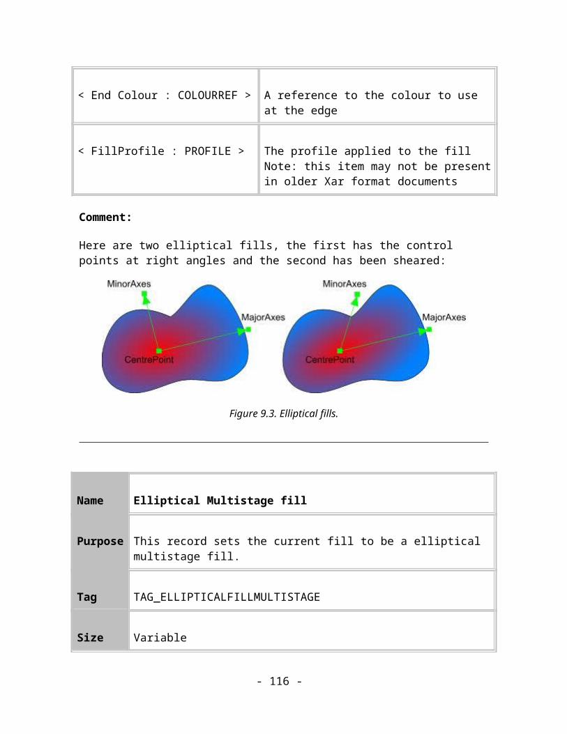
This record sets the current fill to be a linear transparent fill. The transparency level interpolates from the start transparency level at the start point, to the end transparency level at the end point.
Name Circular Transparent fill
Purpose This record sets the current fill to be a circular transparent fill.
Tag TAG_CIRCULARTRANSPARENTFILL
Size 35 (19)
Usage Image. Compulsory.
Data:
< Centre Point : COORD > The centre of the circle that the fill will radiate from
< Edge Point : COORD > A point that lies at the edge of the circle.
< Start Transparency : BYTE > The transparency level at the start point
< End Transparency : BYTE > The transparency level at the end point
< Transparency Type : BYTE > The transparency type to apply.
< TransProfile : PROFILE > The profile applied to the transparencyNote: this item may not be present in older Xar format documents
- 116 -

Comments:
This record sets the current fill to be a circular transparent fill. The transparency level interpolates from the start transparency level at the centre of the circle, to the end transparency level at the edges of the circle.
Name Elliptical Transparent fill
Purpose This record sets the current fill to be a elliptical transparent fill.
Tag TAG_ELLIPTICALTRANSPARENTFILL
Size 43 (27)
Usage Image. Compulsory.
Data:
< CentrePoint : COORD > The position of the centre that the fill will radiate from.
< MajorAxes : COORD > The position of the major axis point.
< MinorAxes : COORD > The position of the minor axis point.
< Start Transparency : BYTE > The transparency level at the start point
< End Transparency : BYTE > The transparency level at the end point
< Transparency Type : BYTE > The transparency type to apply.
- 117 -

< TransProfile : PROFILE > The profile applied to the transparencyNote: this item may not be present in older Xar format documents
Comments:
This record sets the current fill to be an elliptical transparent fill. The transparency level interpolates from the start colour at the centre of the ellipse, to the end transparency level at the edges of the ellipse.
Name Conical Transparent fill
Purpose This record sets the current fill to be a conical transparent fill.
Tag TAG_CONICALTRANSPARENTFILL
Size 35 (19)
Usage Image. Compulsory.
Data:
< Centre Point : COORD > The centre of the “cone”
< Edge Point : COORD > A point that lies at the edge of the “cone”.
< Start Transparency : BYTE > The transparency level at the edge point.
< End Transparency : BYTE > The transparency level at the point on the circle 180 degrees away from the edge point.
< Transparency Type : BYTE > The transparency type to apply.
- 118 -
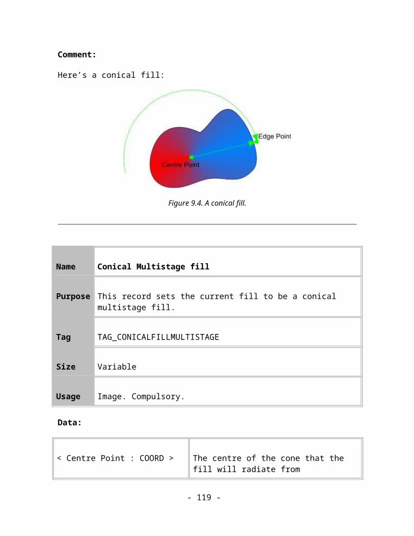
< TransProfile : PROFILE > The profile applied to the transparencyNote: this item may not be present in older Xar format documents
Comments:
This record sets the current fill to be a conical transparent fill. The transparency level interpolates between the start and end transparencies as an imaginary line whose length is the radius of the circle defined by Centre and Edge points sweeps around the circle through 180 degrees. It then interpolates between the end and the start transparencies as the line sweeps out the remaining 180 degrees.
Name Bitmap Transparent Fill
Purpose This record describes a transparent bitmap fill.
Tag TAG_BITMAPTRANSPARENTFILL
Size 47 (31)
Usage Image. Compulsory.
Data:
< BottomLeft : COORD > The position of the bottom left hand corner of the parallelogram.
< BottomRight : COORD > The position of the bottom right hand corner of the parallelogram.
< TopLeft : COORD > The position of the top left hand corner of the parallelogram.
- 119 -

< Start Transparency : BYTE > The transparency level at the start point
< End Transparency : BYTE > The transparency level at the end point
< Transparency Type : BYTE > The transparency type to apply.
< Bitmap : BITMAPREF> The bitmap reference to use as the fill.
< TransProfile : PROFILE > The profile applied to the transparencyNote: this item may not be present in older Xar format documents
Comments:
This record sets the current fill to be a transparent bitmap fill. The geometry of the transparent bitmap is applied in the same way as a normal bitmap fill geometry.
The transparency levels are computed from the intensity of the pixels in the bitmap. Dark pixels are less transparent, light pixels are more transparent.
Name Fractal Clouds Transparent Fill
Purpose This record describes a transparent fractal clouds fill.
Tag TAG_FRACTALTRANSPARENTFILL
Size 64 (48)
Usage Image. Compulsory.
Data:
- 120 -
< BottomLeft : COORD > The position of the bottom left hand corner of the parallelogram.
< BottomRight : COORD > The position of the bottom right hand corner of the parallelogram.
< TopLeft : COORD > The position of the top left hand corner of the parallelogram.
< Start Transparency: BYTE > The transparency level at the start point
< End Transparency: BYTE > The transparency level at the end point
< Transparency Type : BYTE > The transparency type to apply.
< Seed : INT32 > The seed applied to the fractal fill.
< Graininess : FIXED16 > The graininess of the fractal fill.
< Gravity : FIXED16 > The gravity to apply to the fill.
< Squash : FIXED16 > The squash to apply to the fill.
< Resolution : UINT32 > The resolution of this fill (DPI).
< Tileable : BYTE > Flag to say if tileable or not.
< TransProfile : PROFILE > The profile applied to the transparencyNote: this item may not be present in older Xar format documents
Comments:
- 121 -

This record sets the current fill to be a transparent fractal cloud fill. This record describes the transparent fractal fill and all the required parameters to be able to regenerate the fractal pattern when the fill is loaded. The fill geometry is applied in the same way as the Fractal colour fill. Transparency levels are computed from the intensity of the pixels in the fractal.
Name Fractal Noise Transparent Fill
Purpose This record describes a transparent fractal noise (plasma) fill.
Tag TAG_NOISETRANSPARENTFILL
Size 56
Usage Image. Compulsory.
Data:
< BottomLeft : COORD > The position of the bottom left hand corner of the parallelogram.
< BottomRight : COORD > The position of the bottom right hand corner of the parallelogram.
< TopLeft : COORD > The position of the top left hand corner of the parallelogram.
< Start Transparency: BYTE > The transparency level at the start point
< End Transparency: BYTE > The transparency level at the end point
< Transparency Type : BYTE > The transparency type to apply.
- 122 -
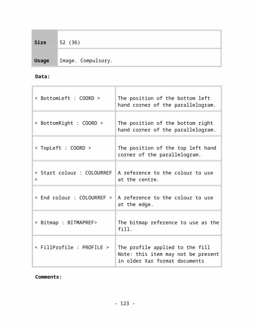
< Graininess : FIXED16 > The graininess of the fractal fill.
< Seed : INT32 > The seed applied to the fractal fill.
< Resolution : UINT32 > The resolution of this fill (DPI).
< Tileable : BYTE > Flag to say if tileable or not.
< TransProfile : PROFILE > The profile applied to the transparencyNote: this item may not be present in older Xar format documents
Comments:
This record sets the current fill to be a transparent fractal plasma fill. This record describes the transparent fractal fill and all the required parameters to be able to regenerate the fractal pattern when the fill is loaded. The fill geometry is applied in the same way as the Fractal plasma colour fill. Transparency levels are computed from the intensity of the pixels in the fractal.
Name Three-level Transparent Fill
Purpose This record sets the current fill to be a three-level transparent fill.
Tag TAG_THREECOLTRANSPARENTFILL
Size 28
Usage Image. Compulsory.
Data:
- 123 -

< Point1 : COORD > The co-ordinate of Level1.
< Point2 : COORD > The co-ordinate of Level2.
< Point3 : COORD > The co-ordinate of Level3.
< Level1 : BYTE > The transparency level at Point1.
< Level2 : BYTE > The transparency level at Point2.
< Level3 : BYTE > The transparency level at Point3.
< Transparency Type : BYTE > The transparency type to apply.
Comments:
This transparency is analogous to the three-colour colour fill attribute. It sets three co-ordinates to specific transparency values and interpolates between those points.
Name Four-level Transparent Fill
Purpose This record sets the current fill to be a four-level transparent fill.
Tag TAG_FOURCOLTRANSPARENTFILL
Size 29
Usage Image. Compulsory.
- 124 -
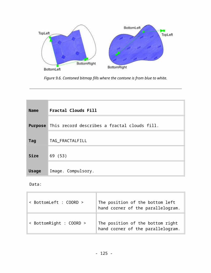
Data:
< Point1 : COORD > The co-ordinate of Level1.
< Point2 : COORD > The co-ordinate of Level2.
< Point3 : COORD > The co-ordinate of Level3.
< Level1 : BYTE > The transparency level at Point1.
< Level2 : BYTE > The transparency level at Point2.
< Level3 : BYTE > The transparency level at Point3.
< Level4 : BYTE > The transparency level at the implied Point4.
< Transparency Type : BYTE > The transparency type to apply.
Comments:
This transparency is analogous to the four-colour colour fill attribute. It sets four co-ordinates to specific transparency values and interpolates between those points.
Name Diamond Transparent Fill
Purpose This record sets the current fill to be a transparent diamond fill.
Tag TAG_DIAMONDTRANSPARENTFILL
- 125 -

Size 43 (27)
Usage Image. Compulsory.
Data:
< Centre Point : COORD > The co-ordinate of the centre of the diamond.
< Right Point : COORD > The co-ordinate of the middle of the right edge of the diamond.
< Top Point : COORD > The co-ordinate of the middle of the top edge of the diamond.
< Level1 : BYTE > The transparency level to use at the centre of the diamond.
< Level2 : BYTE > The transparency level to use at the edges of the diamond.
< Transparency Type : BYTE > The transparency type to apply.
< TransProfile : PROFILE > The profile applied to the transparencyNote: this item may not be present in older Xar format documents
Comments:
This record defines a “diamond” (parallelogram) transparency fill.
- 126 -

Transparent Fill Repeat Methods
Transparent fill repeat methods apply to all of the transparent fill types except flat and conical. They perform the same role for the transparent fills that the Fill Repeat Method attributes do for the colour fills.
The transparent fill repeat records are:
Name Transparent Fill Repeating
Purpose Determines how the transparent fill is tessellated
Tag TAG_TRANSPARENTFILL_REPEATING,TAG_TRANSPARENTFILL_NONREPEATING,TAG_TRANSPARENTFILL_REPEATINGINVERTEDTAG_TRANSPARENTFILL_REPEATING_EXTRA
Size 0
Usage Image. Compulsory.
Comments:
TAG_TRANSPARENTFILL_REPEATING: The transparency is repeated throughout the object, i.e. it is tessellated continuously. This can apply to bitmap, fractal, 3-colour and 4-colour transparencies.TAG_TRANSPARENTFILL_NONREPEATING: The transparency is not repeated at all, and thus might not cover the whole shape that it is applied to. This can apply to all transparency types.TAG_TRANSPARENTFILL_INVERTEDREPEATING: The transparency is repeatedly tessellated, except that each time it is repeated, the bitmap is inverted so that one of its corners touches the equivalent corner on the three other bitmaps touching it. This can apply to bitmap and fractal transparencies.TAG_TRANSPARENTFILL_REPEATING_EXTRA: The transparency is repeated with the start point being the start transparency and a point half-way through the transparency being the end transparency. The transparency then fades back to the start transparency at the end point and then repeats indefinitely. This can apply to linear, circular, elliptical and diamond transparencies.
- 127 -

If a transparency has an unsupported repeat type (e.g. a linear transparency with a TAG_TRANSPARENTFILL_REPEATING) then it is rendered as non-repeating.
Winding Rule Attribute
The winding rule attribute controls which parts of a shape will be filled. It affects both the colour fill and the transparency fill of a shape. The effect of the winding rule becomes most apparent when a path is self-intersecting.
Name Winding Rule
Purpose This record sets the current winding rule.
Tag TAG_WINDINGRULE
Size 1
Usage Image. Compulsory.
Data:
< WindingRule : BYTE > The winding rule for the line.
Winding Rule Value
NonZero 0
EvenOdd 2
- 128 -

Reserved for future use All other values
Comment:
Sets the current winding rule for use when filling shapes. NonZero fills all regions of the shape, no matter how many times the shape covers any region. EvenOdd fills those regions of the shape that are covered by the shape an odd number of times.
Line Attributes
Line attributes affect the way in which lines and the outlines of shapes are rendered (technically: the way in which paths are stroked).
The set of attributes is very similar to those which are available in Postscript.
See Appendix B for a list of the default values for these attributes.
Name Line Colour
Purpose This record sets the current line colour to the colour specified.
Tag TAG_LINECOLOUR
Size 4
Usage Image. Compulsory.
Data:
< Colour : COLOURREF > A reference to a colour.
Comments:
This record sets the current line colour.
- 129 -

Name Standard Line Colours
Purpose These records set the current line colour to be none, uniform black or uniform white.
Tag TAG_LINECOLOUR_NONETAG_ LINECOLOUR BLACKTAG LINECOLOUR _WHITE
Size 0
Usage Image. Compulsory
Comments:
Although the same results can be achieved using the TAG_LINECOLOUR record, these records exist purely because the line colours they define are so common.
TAG_LINECOLOUR_NONE
This record sets the current line colour to be “none”, i.e., indicates that objects should not have a distinct border around them.
TAG_LINECOLOUR_BLACK
This record sets the current line colour to be black, RGB(0,0,0).
TAG_LINECOLOUR_WHITE
This record sets the current line colour to be white, RGB(0xFF,0xFF,0xFF).
Name Line Transparency
- 130 -

Purpose This record sets the current line transparency level
Tag TAG_LINETRANSPARENCY
Size 2
Usage Image. Compulsory.
Data:
< Transparency : BYTE > The transparency level to apply.
< Transparency Type : BYTE > The transparency type to apply.
Comments:
This record sets the current line transparency using the level and type specified.
Name Line Width
Purpose This record sets the current line width.
Tag TAG_LINEWIDTH
Size 4
Usage Image. Compulsory.
Data:
- 131 -
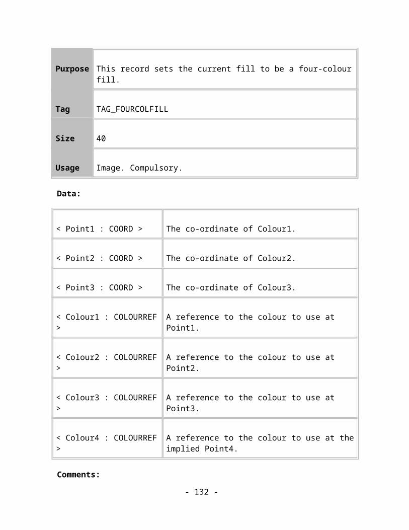
< Line Width : MILLIPOINT > The width of the line in millipoints.
Name Line Caps
Purpose Sets the current cap style.
TagTAG_STARTCAP
TAG_ENDCAP
Size 1
Usage Image. Compulsory.
Data:
< CapStyle : BYTE > The cap style of the line.
Style Value
Butt 0
Round 1
Square 2
Comments:
- 132 -
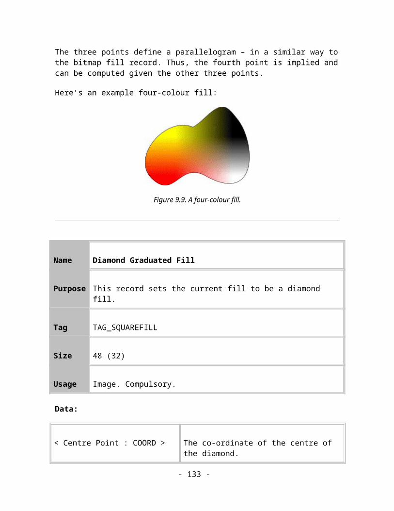
This record sets the current line cap style to either butt, round or square.
NOTE: No currently implemented Readers support a separate “End Caps” attribute. The Start Caps attribute applies its value to both the start and end caps of paths.
Figure 9.12. The three possible line Cap styles.
Name Join Style
Purpose Sets the current join style.
Tag TAG_JOINSTYLE
Size 1
Usage Image. Compulsory.
Data:
< JoinStyle : BYTE > The start cap style of the line.
JoinStyle Value
Mitre 0
- 133 -

Round 1
Bevelled 2
Comments:
This record sets the current line join style to mitred, round or bevelled.
Figure 9.13. The three possible line Join styles.
Name Mitre Limit
Purpose Sets the current mitre limit
Tag TAG_MITRELIMIT
Size 4
Usage Image. Compulsory.
Data:
< MitreLimit : MILLIPOINT > The maximum distance between the join point and the mitre point.
- 134 -

Comments:
The mitre limit defines a cut-off point for mitre join rendering. If the distance between the point of the mitre join and the path point that causes the mitre join is greater than this value, a bevelled join will be rendered instead.
Dash Patterns
Dash patterns can be applied to any path, open or closed. They specify a regular, repeating sequence of gaps in the line. The relative lengths of the gaps and the drawn sections of line between them can be controlled. A number of commonly-used dash patterns are defined in the Xar format and are just referred to by numbers so that these definitions do not have to be transmitted with each file. The default dash patterns are defined in Appendix B.
There are two types of dash pattern record in the Xar format. Dash Pattern Attributes, which apply a dash pattern to a subtree, and Dash Pattern Definitions that define new patterns and apply them to subtrees.
Note that the current records do not allow newly defined dash patterns to be referred back to and used again. This limitation will hopefully be removed in future revisions of the format.
All the default dash patterns can be seen in the line gallery in CorelXARA.
Name Dash Style
Purpose This record describes a dash style which is always applied to a line element or path
Tag TAG_DASHSTYLE
Size 4
Usage Image. Compulsory.
Data:
- 135 -
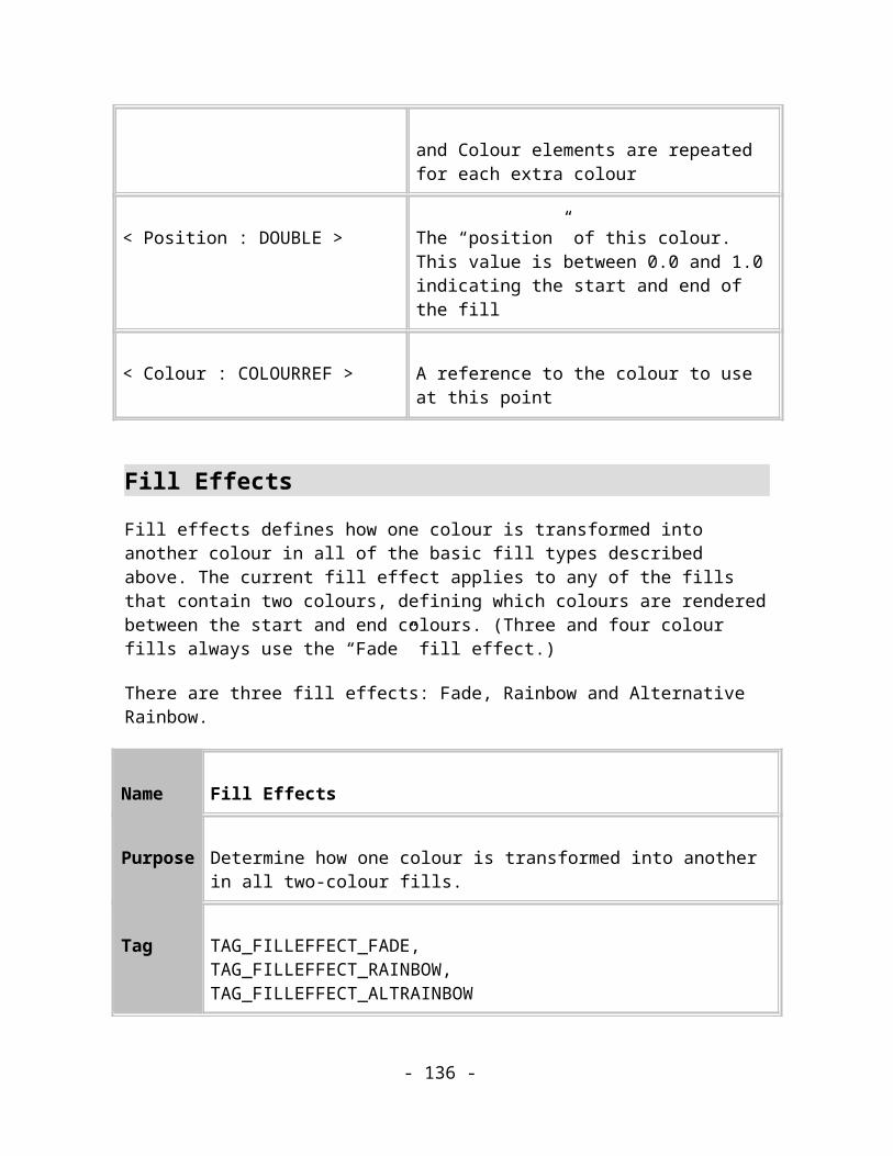
< DashID : INT32 > The id of the dash style to use from the dash style dictionary
Comments:
The dash style id specifies which of the dash styles from the default dash dictionary to use. Note that this ID cannot be a sequence number and so it cannot refer to a dash pattern defined by TAG_DEFINEDASH.
Name Define Dash Style
Purpose This record defines a new dash pattern style and applies it as the current dash pattern.
Tag TAG_DEFINEDASH,TAG_DEFINEDASH_SCALED
Size Variable
Usage Image. Compulsory.
Data:
< DashStart : MILLIPOINT > The offset to apply at the start of this pattern.
< Design LineWidth : MILLIPOINT >
The line width this style is designed relative to. (When the dash pattern scales with the width of the line it’s applied to the scale factor is the ratio between the line width and this, design line width.)
< Elements : UINT32 > The number of elements that make up this dash style definition.
- 136 -

< DashDef : MILLIPOINT >* The array of mark and space lengths starting with a mark.
Comments:
Defines a new style of dash pattern and applies it as the current dash pattern attribute. The definition consists of an array of interleaved Mark and Space dash lengths. The first distance is drawn in the line colour, the second in the no colour line style and so on; Mark, Space, Mark, Space... The dash start distance allows an extra offset to be applied at the start of the dash pattern of the first element to be drawn.
Note: this dash pattern definition applies its result to the subtree as an attribute. It cannot be referred back to by later TAG_DASHSTYLE records.
The TAG_DEFINEDASH_SCALED variant indicates that its dash pattern should be scaled so that its proportions to the actual line width are the same as its proportions to the design line width.
An illustration of how the data relates to one of the definitions is shown below.
Figure 9.14. A Dash Pattern Definition.
A list of the Default Dash Patterns is given in Appendix B
Arrowheads
Arrowheads are attributes that cause small paths to be drawn tangentially on the ends of open paths. They don’t affect the rendering of the path itself.
The Xar format only supports predefined arrowheads at this time.
- 137 -
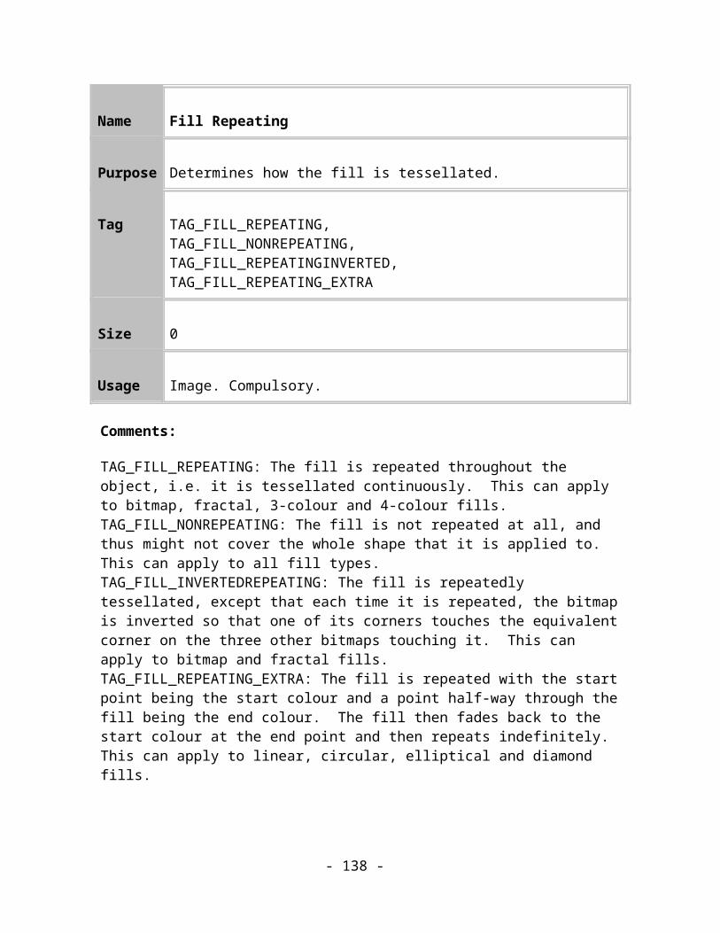
Name Arrowheads
Purpose Describe the start and end arrow heads which apply to a open paths.
Tag TAG_ARROWHEADTAG_ARROWTAIL
Size 12
Usage Image. Compulsory.
Data:
< ArrowID : INT32 > The id of the arrowhead to use from the arrowheads dictionary.
< ScaleWidth : FIXED16 > The scaling to apply to the width of the arrow
< ScaleHeight : FIXED16 > The scaling to apply to the height of the arrow
Comments:
An arrow head attribute record specifies an arrow head by either referring to the arrow head definition record (i.e. the record number of the arrow head definition), or by specifying a default arrow head (see Appendix B).
A negative ArrowID specifies one of the default arrowheads.
A positive ArrowID specifies the sequence number of a record that defines a new arrowhead. The specified record must be an arrowhead definition record, TAG_DEFINEARROW. This feature is not implemented in the current version of the Xar format.
The arrowhead path will automatically be scaled proportionally to the current line width. (See the Arrowhead definitions in Appendix B for more information about how arrowheads
- 138 -

are defined and scaled.) The Width and Height Scale factors in this record allow the scaling of an individual arrowhead to be adjusted.
TAG_ARROWHEAD defines the arrow that should be drawn tangentially to the first point in an open path.
TAG_ARROWTAIL defines the arrow that should be drawn tangentially to the last point in an open path.
Colour records
Colours are used in all of the fill attributes described above and in other attributes such as LineColour. The form they take in those records is just single word that refers to a full colour definition somewhere else, a COLOURREF.
Colour references
All records that reference a colour do so using a COLOURREF value. This value is either the sequence number of the record that defines the colour or a reference to a default colour. This mechanism is described in the section Reusable Data Records.
The default colours are defined in Appendix B.
Colour Definition Records
The following records define new colours:
Name Define RGB Colour
Purpose This record defines a simple RGB colour to the system.
Tag TAG_DEFINERGBCOLOUR
Size 3
Usage Image. Compulsory.
Data:
- 139 -
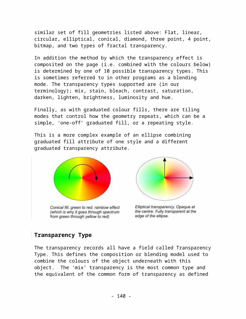
<Simple RGBColour> A RGB representation of the colour.
<Simple RGBColour> ::= <Red : BYTE> <Green : BYTE> <Blue : BYTE>
Comments:
This record holds a simple RGB colour definition. It is intended for use in Web-publishable files – it contains enough information to define a colour for screen display but not enough for use in paper publishing. The TAG_DEFINECOMPLEXCOLOUR record contains more detailed information suitable for paper publishing.
Name Define Complex Colour
Purpose This record defines a complex colour to the system.
Tag TAG_DEFINECOMPLEXCOLOUR
Size Variable
Usage Image. Compulsory for readers.
Data:
<Simple RGBColour> The RGB definition of the colour.
<ColourModel : BYTE> The colour model that this colour is defined in. See below for possible values.
<ColourType : BYTE> The type of colour, and extra type-dependent values. See below for possible values.
- 140 -

<EntryIndex : UINT32> The position of this colour in any colour list, starting with 0 for the first.
<ParentColour : COLOURREF> A reference to a parent colour. This is only relevant for some ColourTypes; other types should set this value to 0.
<ColourDescription> The actual data for the colour. (see below)
<ColourName : STRING> The name of the colour. Can be an empty string (see below).
<Simple RGBColour> ::= <Red : BYTE> <Green : BYTE> <Blue : BYTE>
<ColourDescription>::= <Component1 : UINT32> <Component2 : UINT32> <Component3 : UINT32> <Component4 : UINT32>
Comments:
This record defines a colour in terms that are suitable for further editing and for paper publishing. Such definitions are not normally used in files intended for publishing on the Web because of their large size overhead.
Fields in a TAG_DEFINECOMPLEXCOLOUR record
Simple RGB Colour
The Simple RGB Colour field holds the RGB colour value that the Writing application computed based on all the other information in the definition.
It can be used as fallback information for Readers which don’t understand the full definition of the colour:Rendering modules which only render to screen just need to use this information and can ignore the remainder of the definition.Editing programs, which don’t support the full complex colour definition (e.g. the colour model is unknown), should at least be able to deal with the simple RGB information.
This field also helps to make Complex colours backwards compatible: if new colour models are added some time in the future, existing Readers can still use the RGB information.
- 141 -
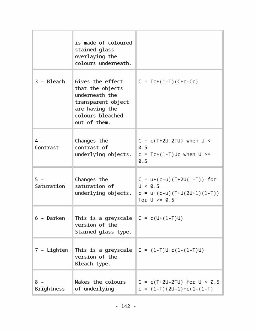
Colour Models
A colour model describes the way in which three or more fundamental components can be mixed together to represent a spectrum of colours. Illustration typically offer their users several of these models and it is important that the colour definitions created by the user are stored in their original form rather than converting them to some standard format because conversions between colour models usually results in a small loss of accuracy.
The colour models defined in the Xar format and their related Colour Description fields are described in the following sections.
The Colour Model field determines how the Colour Description, Colour Type and Parent Colour fields should be interpreted.
All colour models use the Colour description. This is generic across all colour models and always holds four colour components regardless of the colour model and type. The use of four colour components gives consistency across the various colour models and colour types, and may provide some scope for future expansion. Note that the use of 32-bit fields for these components means that complex colour definition is very accurate. At the moment most video cards maximum colour depth is 8 bits per RGB component but some graphics experts claim that this isn’t accurate enough and there are video cards available which have 16 bits per gun.
Colour component values are always stored in a 32 bit integer but generally this represents a value from 0.0 to 1.0 as a fixed point number with the binary point between bits 23 and 24 (a fixed24 value). This is scaled into the full integer range of the Component item (i.e. even Hue, which is normally represented in degrees between 0 and 360, is represented in this form). However, there are the following exceptions to this rule: in the Pantone model, the Pantone colour number is a full range integer and in the Shades model, the components must store a number between -1.0 and +1.0.
RGB (ColourModel 2)
This is the colour model that most people are familiar with. It is the model used by computer screens to display colours. The colour description contains three components, describing the amounts of Red, Green and Blue in this colour. 0 means no colour component present, 1.0 means the full amount of this colour component is present.
< Red : UINT32> Red
< Green : UINT32> Green
- 142 -

< Blue : UINT32> Blue
< Reserved : UINT32> 0x0
CMYK (ColourModel 3)
This is the colour model used by commercial printers and most ink-jet printers. The CMY coloured inks can be mixed on the normally white printed page to reproduce most colours. The K “Key” component is used to print pure black graphics and reinforces dark colours and grey shades, which would otherwise appear very “muddy”.
The colour description contains four components, describing the amounts of Cyan, Magenta, Yellow and Key for this colour. 0 means no colour component present, 1.0 means the full amount of this colour component is present.
< Cyan : UINT32> Red
< Magenta : UINT32> Green
< Yellow : UINT32> Blue
< Key : UINT32> Key
HSV (ColourModel 4)
This is the colour model familiar to Artists. Hue is the pure pigment, represented by the angle around an imaginary circle which has the full spectrum of pigments wrapped around it. Saturation controls the amount of white added to the pigment, the smaller the saturation the greater the amount of added white. The Value controls the amount of black added, the greater the value the greater the amount of black added.
The colour description contains three components, describing the amounts of Hue, Saturation and Value for this colour. 0 Hue means red, 1.0 means red again. 0 Saturation means the full amount of white added, 1.0 means no white added. 0 Value means the full amount of black added, 1.0 means no black has been added.
- 143 -
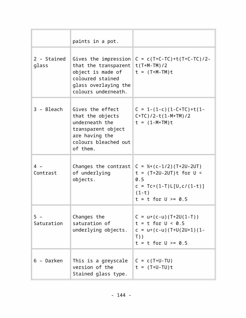
< Hue : UINT32> Hue
< Saturation : UINT32> Saturation
< Value : UINT32> Value
< Reserved : UINT32> 0x0
Greyscale (ColourModel 5)
The greyscale model is very simple and just describes the grey tonal value for this colour in a range from white to black. The colour description therefore only contains one component, the value of the greyscale. 0 means no colour is present, hence fully black, 1.0 means the full amount of grey is present, hence fully white.
< Grey : UINT32> Grey
< Reserved : UINT32> 0x0
< Reserved : UINT32> 0x0
< Reserved : UINT32> 0x0
ParentColour
Where required, the parent colour is specified by its sequence number. The parent colour record must appear before the record that references it. See Colour Parentage below for rules to follow when using parent colours.
ColourType
The colour type describes whether the colour is a normal colour, a spot colour, a tint, a shade or a linked colour. These types are independent of the colour model.
Normal (ColourType 0)
- 144 -

This is just a normal, plain and simple colour. It can also be referred to as a “process” colour in the user interface. In a colour separation process, the normal colour is split into the required components, usually Cyan, Magenta, Yellow and Key (Black), and sent out to the printer.
ParentColour is ignored.
ColourDescription simply describes the colour in the specified colour model.
Spot (ColourType 1)
A Spot colour behaves like a Normal colour in most respects except when colour separating the image. In that case it defines that a separate printing plate should be devoted to this colour. The plate will be printed using a special ink, often defined by the Pantone colour system which is capable of describing such inks as are not easily represented on-screen such as metallic or scratch-off ink.
ParentColour is ignored.
ColourDescription simply describes the colour in the specified colour model.
Tint (ColourType 2)
This colour is a tint of another, “parent” colour. That means that it is a whiter version of the parent colour.
ColourModel is ignored, as Tint Colours automatically inherit the colour model of their parent.
ParentColour references the parent colour to inherit from.
ColourDescription specifies a tinting value, which defines how the colour is tinted from the parent colour. This is a mixing coefficient, where 0 produces the parent colour, 0.5 produces a 50% mix of the parent colour and white, and 1.0 produces white.
Linked (ColourType 3)
This colour takes some of its components from its parent colour and specifies the rest itself. This type of colour is very similar to Tints and Shades except that there is no relative linkage between itself and its parent – the components it takes from its parent are used exactly as the parent defines them.
ColourModel is ignored, since Linked Colours automatically inherit the colour model of their parent.
ParentColour references the parent colour to inherit from.
- 145 -

ColourDescription contains the same number of components as the parent colour. Where a component is inherited from the parent, the corresponding component contains the magic number F8000000.
Shade (ColourType 4)
This colour is a combined tint and shade of the specified Parent Colour.
ColourModel is ignored, since Shade Colours automatically inherit the colour model of their parent.
ParentColour references the parent colour to inherit from.
ColourDescription contains two shading values defined in HSV space: the relative Saturation for this shade and the relative Value for this shade. These are mixing coefficients, in the range -1.0 to +1.0. These are the only components that can go negative. The saturation coefficient specifies mixing in the Saturation axis, while the value coefficient specifies mixing in the Value axis, of the HSV colour space. Negative values indicate a mixing between 0.0 and the parent component, while positive values indicate a mixing between the parent component and 1.0, such that a shading value of 0.0 results in the parent component being directly inherited by the shade colour. For example, as shown in this illustration (laid out just as the Xara colour editor shows shades), the shading values would be S=0.7, V=-0.25 in order to place the shade colour in the given position relative to its parent colour.
Figure 9.15. The relationship between a shade and its parent colour.
ColourName
The colour name can be blank and the presence of a colour name or the lack of it can be used to control the behaviour of the colour in the UI of editing applications.
- 146 -
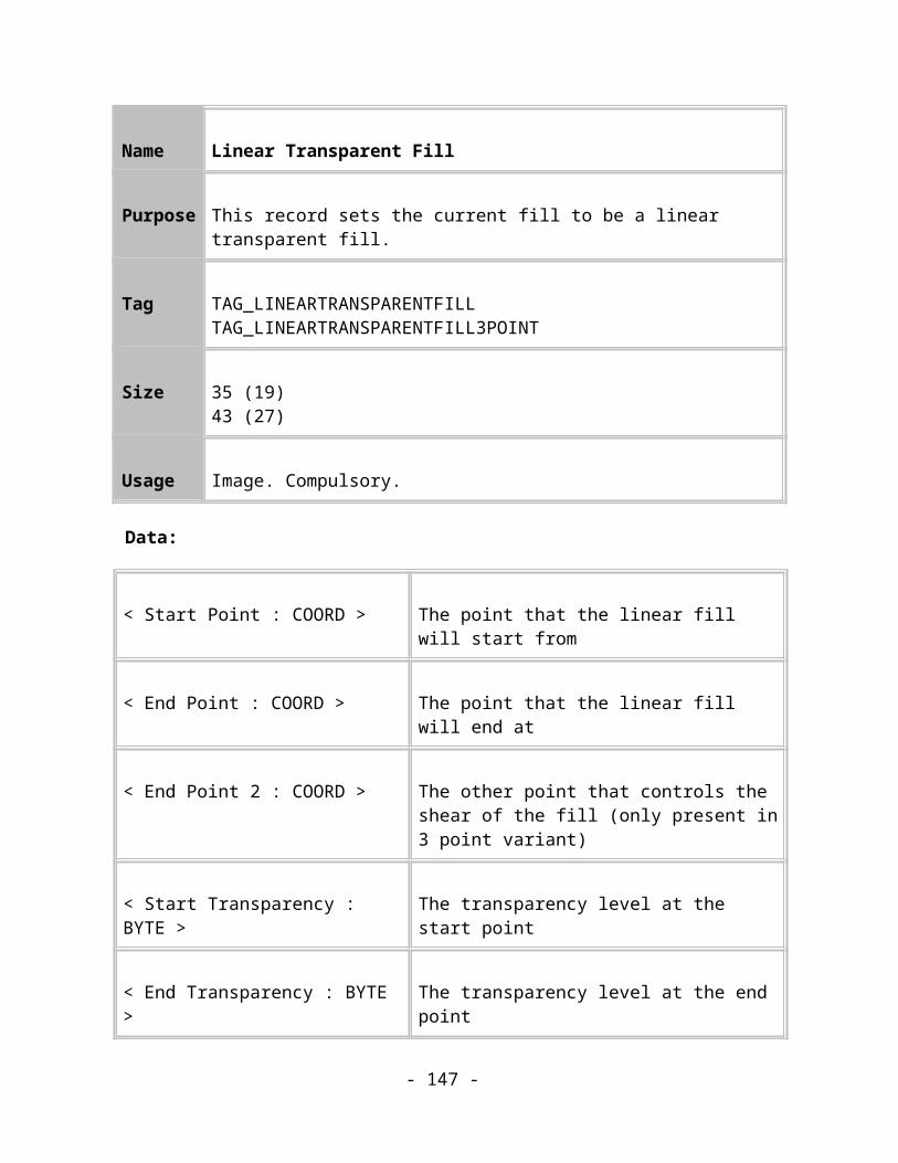
A colour with a blank ColourName is called a Local Colour. In XaraX¹, local colours are not shown in the various colour lists and cannot be used as parent colours.
A colour with a name is called a Named Colour (bet that surprised you!). In XaraX¹, named colours are listed with other colours and can be used as parent colours.
EntryIndex
This is 0 for Local colours. For a Named colour it dictates the position in which the colour will be displayed in any colour lists in the editor’s user interface, where 0 is the first entry in the list, usually the leftmost or topmost item. This number allows the user to re-arrange the colour lists in his editor and to have his arrangement preserved when he edits the document in future.
Colour parentage
The rules describing how colours are linked to their parent colours are:
1. Parent colours must be Named. 2. Colour types Normal and Spot cannot have a Parent colour.
3. Colour types Linked, Tint and Shade must have a Parent colour.
4. All descendants of a Spot colour must be Tints.
5. There must not be a circular reference of parents. A colour cannot be its own parent.
6. There is no limit to the depth of colour “family trees”, i.e. A colour may have any number of children, grandchildren, etc.
The statically defined colours are listed in Appendix B.
User Attributes
User Attributes allow the user to associate data, a “Value”, with an object through a “Key”. The key effectively defines a new attribute. Since there is an extra level of indirection in determining the attribute’s type, User Attributes should be used judiciously to ensure efficient processing of the file. New key values will be allocated by Xara Group Ltd.
- 147 -

Name User Value
Purpose Provides user defined attributes.
Tag TAG_USERVALUE
Size Variable
Usage Image. Optional.
Data:
< Key : String > The key defining the type of user attribute.
< Value : String > The value associated with the object and key.
Comments:
At present there is only one Key recognized in the Xar format, “Web address”. The Value associated with this key is a URL of the user’s choice. This method of specifying web addresses has been superseded by TAG_WEBADDRESS and TAG_WEBADDRESS_BOUNDINGBOX below.
Name Web Address and Web Address Bounded
Purpose Represents a web address attribute.
Tag TAG_WEBADDRESSTAG_WEBADDRESS_BOUNDINGBOX
- 148 -

Size Variable
Usage Image. Optional.
Data:
If BOUNDINGBOX< BottomLeft : COORD >
The bottom left of the clickable rectangle. Note: this is an interleaved coordinate
If BOUNDINGBOX< TopRight : COORD >
The top right of the clickable rectangle. Note: this is an interleaved coordinate
< URL : String > The URL associated with the object.
< Frame : String > The target frame associated with the object.
Comments:
These records have superseded the use of TAG_USERVALUE records. They allow the target frame to be specified and TAG_WEBADDRESS_BOUNDINGBOX allows the clickable area to be set to the bounds of the object that has the attribute applied. Note: the bounding rectangle is only stored so readers that cannot calculate the bounding rectangle of the object can read it. Any reader that can calculate the bounding rectangle should do so.
Feather
The feather attribute fades the edge of the object using transparency. The size and transparency profile of the feathered edge can be controlled.
Name Feather
Purpose Defines a feather attribute.
- 149 -

Tag TAG_FEATHER
Size 20
Usage Image. Compulsory.
Data:
< Size : MILLIPOINT > The size of the feathered region.
< TransProfile : PROFILE >
The profile applied to the transparency
Comments:
This attribute causes the object to be rendered with a graduated transparent edge. It is commonly used when compositing bitmaps allowing a very smooth join to be made.
Imagesetting Attributes
These records define the attributes that can be used to provide correct images when printing to multiple printers’ plates.
Overprinting the fill is most commonly used to overprint dark coloured text.
Overprinting the line overcomes possible misregistration problems.
Objects with the PRINTONALLPLATESON attribute appear on all separations. Its main use is creating custom printers’ marks.
See Appendix B for a list of the default values for these attributes.
Name Imagesetting Attributes On
- 150 -

Purpose These records determine whether objects exhibit imagesetting characteristics.
Tag TAG_OVERPRINTLINEON, TAG_OVERPRINTFILLON, TAG_PRINTONALLPLATESON
Size 0
Usage Image. Optional.
Comments:
The effects of these records can be cancelled by the equivalent “OFF” records.
Name Imagesetting Attributes Off
Purpose These records determine whether objects exhibit imagesetting characteristics.
Tag TAG_OVERPRINTLINEOFF, TAG_OVERPRINTFILLOFF, TAG_PRINTONALLPLATESOFF
Size 0
Usage Image. Optional.
Comments:
These records cancel the effects of the equivalent “ON” records.
- 151 -

Current Attributes
Current Attributes are the attributes that will be used when creating new objects in the drawing. Different current attributes can be defined for different types of object though at present only text objects can be controlled independently. This means that new text objects can have one set of attributes and all other types of object can have a different set. The current attributes are stored as children of the current attribute record. Any attributes that should be 152ezier152l152ed when being applied to a new object (e.g. fills, transparencies etc) also have a current attribute bounds record written out immediately following the attribute record. This allows the application to transform the attribute to fit the new objects bounding rectangle.
Name Current Attributes
Purpose Defines the attributes used for creating new objects.
Tag TAG_CURRENTATTRIBUTESTAG_CURRENTATTRIBUTES_PHASE2
Size 1
Usage Application. Optional.
Data:
< Group : BYTE > The group defining the set of current attributes being defined. 1 – ink objects, 2 – text objects
Comments:
TAG_CURRENTATTRIBUTES and TAG_CURRENTATTRIBUTES_PHASE2 have identical meanings in the XAR file format but some XAR Readers fail when TAG_CURRENTATTRIBUTES has a Group byte with any value except 1 and 2. The TAG_CURRENTATTRIBUTES_PHASE2 record allows the Group byte to contain any value .
XAR Writers should use TAG_CURRENTATTRIBUTES to represent Groups 1 and 2 and TAG_CURRENTATTRIBUTES_PHASE2 for any other Group value.
- 152 -

Name Current Attribute Bounds
Purpose Defines the bounding rectangle of a current attribute.
Tag TAG_CURRENTATTRIBUTEBOUNDS
Size 16
Usage Application. Optional.
Data:
< BottomLeft : COORD > The bottom left coordinate of the previous attribute’s bounding rectangle
< TopRight : COORD > The top right coordinate of the previous attribute’s bounding rectangle
- 153 -

QuickShapesQuickShapes are rectangles, ellipses, regular polygons and other rotationally symmetric shapes.
Figure 10.1. A selection of QuickShapes.
All of these objects are represented in the Xar format by minimal data sets – the records contain just enough data to represent the QuickShape and no more. A renderer uses that data to construct the actual path to be rendered – the paths themselves are not held in the Xar format. Obviously, the amount of information needed to store ellipses and rectangles is much less than that needed for the more complex polygons and shapes. For this reason, there are several different types of QuickShape record, each of which is tailored to hold just the amount of information that type of QuickShape needs and no more. This helps to maintain the efficiency of the simple, common QuickShapes such as Rectangles.
Since the more complex QuickShapes are all controlled by bounding ellipses the simple ones, such as Rectangles, are also expressed in those terms. This makes it possible to use common code to handle all the different cases.
All QuickShapes except ellipses can have rounded corners.
All QuickShapes except ellipses can be stellated – that is, each edge is divided in two and the new edge-centre point can have a different radius than the corner points at either end of the edge.
All QuickShapes except ellipses can be “reformed” – that is, each edge (or half-edge if the QuickShape is stellated) is not a straight line, it’s a Bezier segment.
Notes about the record descriptions
Full descriptions of the fields in all of the QuickShape records are collected together at the bottom of this chapter rather than repeated along with every record description.
- 154 -
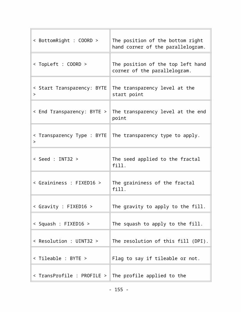
Upright Rectangles and Ellipses
One of the simplest and commonest QuickShapes is an upright rectangle. In this case, all that is required is the size and position of the basic rectangle. There is a second form of the record, which stores an upright rounded rectangle. This has one extra piece of information, which is the rounding radius applied to the corners. The upright ellipse also only needs a position and the sizes of its axes to describe it fully.
Figure 10.2. Information stored in simple ellipse and rectangle records.
Name Upright Rectangle and Upright Ellipse
Purpose This record describes a basic upright rectangle or ellipse
Tag TAG_RECTANGLE_SIMPLETAG_ELLIPSE_SIMPLE
Size 16
Usage Image. Compulsory.
Data:
- 155 -

< Centre : COORD > The centre point of the rectangle.
< Width : MILLIPOINT > The width of the (bounding) ellipse.
< Height : MILLIPOINT > The height of the (bounding) ellipse.
Comments:
This record describes a simple upright rectangle. In TAG_RECTANGLE_SIMPLE records, the ellipse bounds the upright rectangle as shown in figure 10.2. This information should be passed to your standard QuickShape interpreter along with default values such as four sides, no stellation, etc., etc…
(The ellipse describes the upright rectangle by assuming that the corners of the rectangle are equally spaced around the ellipse. This is the same algothrim that’s used to position the vertices of more complex polygons.)
While this method of describing rectangles may appear to be over-complex, it pays off in the long-run when you come to implement the other QuickShapes and you’ll notice that the description takes no more bytes than a pair of co-ordinates would.
Name Upright Rounded Rectangle
Purpose This record describes an upright rounded rectangle
Tag TAG_RECTANGLE_SIMPLE_ROUNDED
Size 24
Usage Image. Compulsory.
Data:
- 156 -

< Centre : COORD > The centre point of the rectangle.
< Width : MILLIPOINT > The width of the bounding ellipse.
< Height : MILLIPOINT > The height of the bounding ellipse.
< Roundness : DOUBLE > The roundness of the curved corners of the rectangle.
Comments:
This record describes a simple upright rectangle that has rounded corners. The roundness value gives the ratio of the radius of the corner curve to the radius of the major axis of the bounding ellipse.
(The ellipse describes the upright rectangle by assuming that the corners of the rectangle are equally spaced around the ellipse. This is the same algothrim that’s used to position the vertices of more complex polygons.)
Non-upright Rectangles and Ellipses
The following more complex forms, instead of storing just a simple width and height, store the major and minor axis positions. This means that they can describe rotated and skewed rectangles.
Name Non-upright Rectangles and Ellipses
Purpose These records describe rectangles and ellipses that can be rotated and skewed.
Tag TAG_RECTANGLE_COMPLEXTAG_ELLIPSE_COMPLEX
Size 24
Usage Image. Compulsory.
- 157 -

Data:
< Centre : COORD > The centre point of the rectangle.
< MajorAxis : COORD > The major axis point of the rectangle relative to the centre.
< MinorAxis : COORD > The minor axis point of the rectangle relative to the centre.
Comments:
This record describes a non-upright rectangle. The edges of the rectangle in TAG_RECTANGLE_COMPLEX are parallel to the axes of the ellipse and the ellipse bounds the rectangle in a similar way to the upright records described above. The Rectangle has the same centre as the ellipse.
Name Complex Rounded Rectangle
Purpose This record describes a more complex rectangle record
Tag TAG_RECTANGLE_COMPLEX_ROUNDED
Size 32
Usage Image. Compulsory.
Data:
< Centre : COORD > The centre point of the rectangle.
< MajorAxis : COORD > The major axis point of the rectangle relative to the centre.
- 158 -
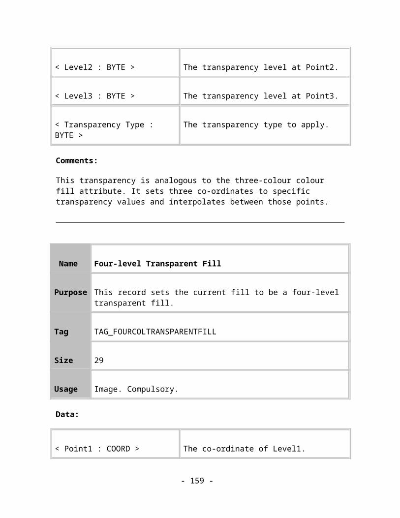
< MinorAxis : COORD > The minor axis point of the rectangle relative to the centre.
< Roundness : DOUBLE >
The roundness of the curved corners of the rectangle
Comments:
This record describes a more complex form of a non-upright rectangle that has rounded corners. The rectangle is described in the same way as described for TAG_RECTANGLE_COMPLEX above. The roundness value gives the ratio of the radius of the corner curve to the radius of the major axis of the bounding ellipse.
Polygons
A polygon is a many sided figure and hence requires an extra “number of sides” field. The major and minor axes define the enclosing ellipse.
Figure 10.3. A simple polygon QuickShape.
There is no “Simple” record to define upright polygons because the concept of uprightness doesn’t apply so well to polygons. The simplest form of Polygon record is TAG_POLYGON_COMPLEX:
Name Polygon
- 159 -

Purpose This record describes a relatively simple polygon
Tag TAG_POLYGON_COMPLEX
Size 26
Usage Image. Compulsory.
Data:
< NumberOfSides : UINT16 >
Number of sides on the polygon(value between 3-99)
< Centre : COORD > The centre point of the polygon.
< MajorAxis : COORD > The major axis point of the enclosing ellipse relative to the centre.
< MinorAxis : COORD > The minor axis point of the enclosing ellipse relative to the centre.
Comments:
This record describes a simple rotated polygon. It is not stellated, reformed or rounded. For more information about the meanings of the various fields, see below.
Name Rounded Polygon
Purpose This record describes a polygon with rounded corners
- 160 -

Tag TAG_POLYGON_COMPLEX_ROUNDED
Size 34
Usage Image. Compulsory.
Data:
< NumberOfSides : UINT16 >
Number of sides on the polygon(value between 3-99)
< Centre : COORD > The centre point of the polygon.
< MajorAxis : COORD > The major axis point of the enclosing ellipse relative to the centre.
< MinorAxis : COORD > The minor axis point of the enclosing ellipse relative to the centre.
< Roundness : DOUBLE > The roundness of the curved corners of the rectangle
Comments:
This record describes a simple rotated polygon with rounded corners. For more information about the meanings of the various fields, see below.
Name Rounded Polygon with Reformed edges
Purpose These record describes a polygon with rounded corners and reformed edges
- 161 -

Tag TAG_POLYGON_COMPLEX_ROUNDED_REFORMED
Size Variable
Usage Image. Compulsory.
Data:
< NumberOfSides : UINT16 >
The number of sides the polygon has.
< MajorAxis : COORD > The major axis point of the polygon relative to the centre.
< MinorAxis : COORD > The minor axis point of the polygon relative to the centre.
< Matrix : MATRIX > The matrix which transforms the centre of the QuickShape into position and which…
< Curvature : DOUBLE > The roundness of the curved corners of the polygon.
< EdgePath : PATH > The path along the edges of the polygon.
Comments:
This record describes a polygon with rounded corners and reformed edges. For more information about the meanings of the various fields, see below.
Name Polygon with all the trimmings
- 162 -
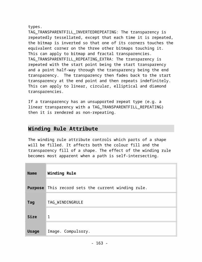
Purpose These record describes a polygon with every possibly variation applied to it
Tag TAG_POLYGON_COMPLEX_ROUNDED_STELLATED_REFORMED
Size Variable
Usage Image. Compulsory.
Data:
< NumberOfSides : UINT16 >
The number of sides the polygon has.
< MajorAxis : COORD > The major axis point of the polygon relative to the centre.
< MinorAxis : COORD > The minor axis point of the polygon relative to the centre.
< Matrix : MATRIX > The matrix which transforms the centre of the QuickShape into position.
< StellationRadius : DOUBLE >
The fraction of the Radius describing an ellipse on which the inner points of the star are placed.
< StellationOffset : DOUBLE >
The angle in degrees by which the inner points of the star are offset from the outer points.
< PrimaryCurvature : DOUBLE >
The roundness of the curved corners of the rectangle.
< SecondaryCurvature : DOUBLE >
The roundness of the internal corners of the stellated rectangle.
- 163 -
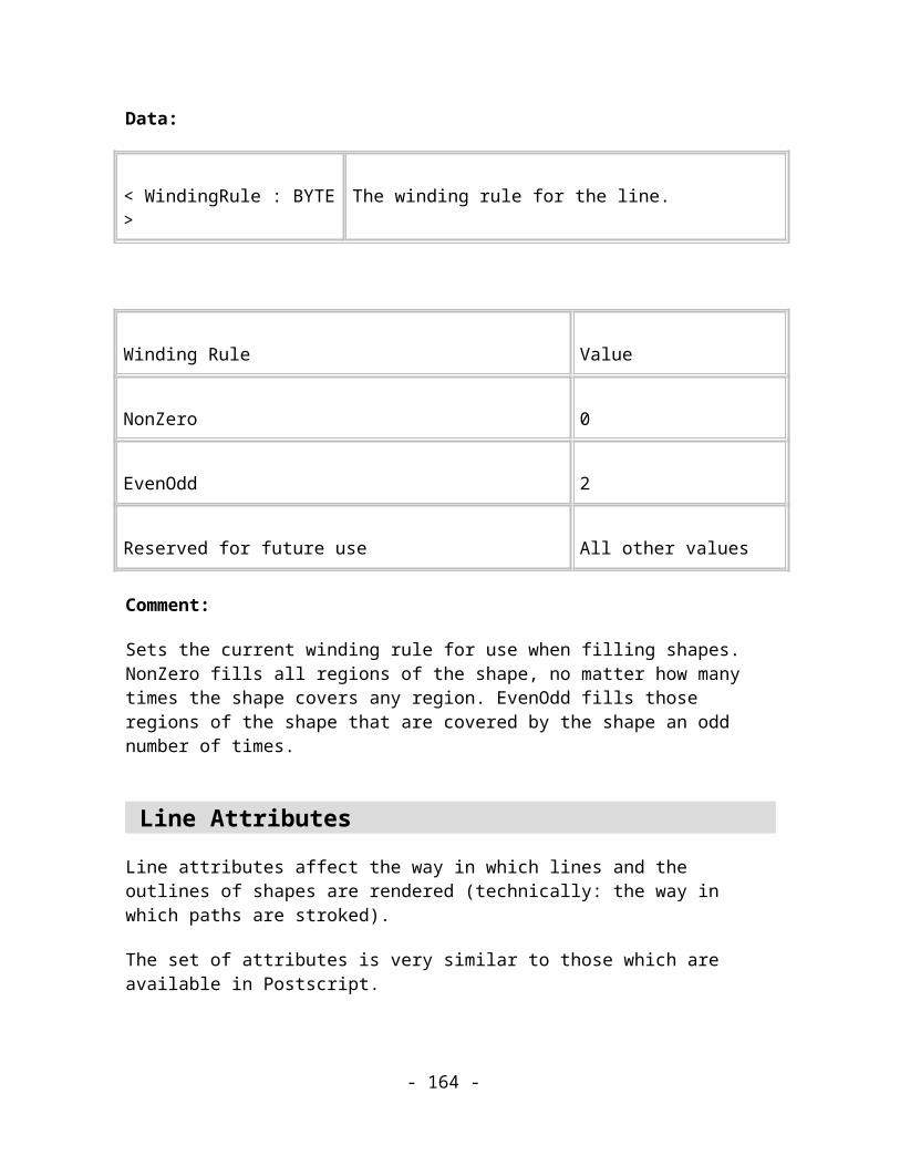
< EdgePath1 : PATH > The path along the edges of the rectangle or the clockwise edges of the stellated rectangle.
< EdgePath2 : PATH > The paths along the anti-clockwise edges of the stellated rectangle.
Comments:
This is the most complex, and thus the most capable, QuickShape description record. It can describe any QuickShape including all those listed above, so if a Writer only intends to deal with one QuickShape record this should be the one. Note that doing so would waste space by holding information that isn’t really needed for the simpler QuickShapes.
Explanations of all the fields in QuickShape records
Number of sides
This is a value between 3 and 99 that corresponds to the number of sides, and thus the number of vertices, of the polygon. The vertices are evenly distributed around the bounding ellipse. This is achieved by conceptually placing points at equal distances around an upright circle whose major axis point is at (1,0), minor axis (0,1). That circle and the points on it are then transformed to lie on the ellipse by transforming the unit major and minor axes of the imaginary circle onto the real major and minor axes of the ellipse.
The first vertex of the polygon is rotated ((360/Number of sides)/2) degrees away from the Major axis – in other words one face of the polygon is always perpendicular to the Major axis of the imaginary circle. The other vertices are placed at (360/Number of sides) degrees separations around the imaginary circle.
Centre point
This defines where the centre of the QuickShape is in normalised space.
Matrix
This defines where the centre of the QuickShape is in normalised space, and a transformation that is applied to the whole QuickShape. This is usually used for Reformed Quickshapes that need to preserve information about any transformations that have been applied to the QuickShape and that thus affect its reformed edges.
- 164 -
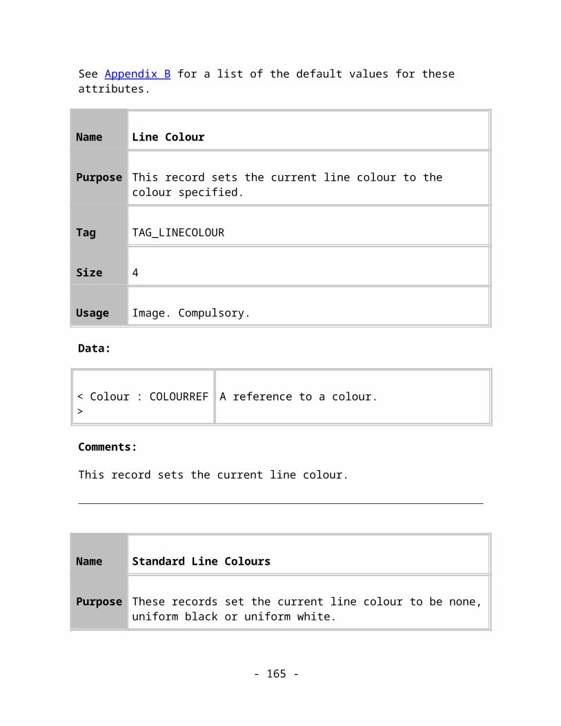
Major axis
This defines where the major axis point is in normalised space. Note: The “Major axis” is not necessarily longer than the “Minor axis” – these are just convenient labels.
The MajorAxis MILLIPOINT fields represent the horizontal distance to the Major Axis point whereas the MajorAxis COORD fields represent that point directly.
Minor axis
This defines where the minor axis point is in normalised space. Note: The “Minor axis” is not necessarily shorter than the “Major axis” – these are just convenient labels.
The MinorAxis MILLIPOINT fields represent the horizontal distance to the Minor Axis point whereas the MinorAxis COORD fields represent that point directly.
Curvature, PrimaryCurvature and SecondaryCurvature
If curvature is applied to the shape (rounded corners) then the Curvature or PrimaryCurvature field is a ratio that describes how to generate the curved outer corners of the QuickShape.
The radius of the corner is controlled by the PrimaryCurvature multiplied by the length of the major axis. If you then move along the line from the corner point under consideration to the nest point on the QuickShape (stellated or not) by that distance you arrive at a point called the “primary curvature point”. (This corresponds to one of the editing blobs in CorelXARA.) This is illustrated below:
- 165 -

Figure 10.4. The computation of rounded corners from the Primary Curvature.
Do the same in the other direction and you can then fit a 166ezier curve segment between these two curvature points. The 166ezier control handles lie on the line between the primary curvature point and the corner point, 0.552 of the way between. This is the primary curvature. This is illustrated by:-
- 166 -
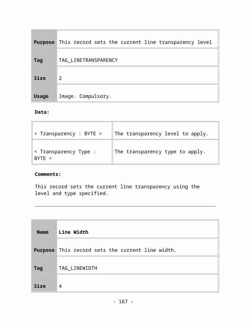
Figure 10.5. The computation of rounded corners from the Primary Curvature
If stellation is applied in the same record as rounded corners then the SecondaryCurvature field describes how to generate the curved corners at the internal, stellation points. The process is analogous to that described above for the PrimaryCurvature.
At the time of writing any stellated QuickShapes with rounded corners will always have the same value in the PrimaryCurvature and SecondaryCurvature fields for any given QuickShape. This is simply because the existing editing tools only allow the user to set one corner radius which applies to both Corner and Stellation points. However, this may not always be true in the future.
EdgePath, EdgePath1 and EdgePath2
Reformed QuickShapes have edges that are curved instead of straight. This means that instead of plotting a straight path plotted between corner points stellation points and curve points, a Bezier path is plotted.
When the shape is not stellated, there is only one path, EdgePath. When the shape is stellated, there are two edge paths called EdgePath1 and EdgePath2. The edge paths are plotted between different points depending on whether the shape is stellated and/or rounded.
Plot Edge Path EdgePath EdgePath1 EdgePath2
Not Rounded
Not Stellated
From: Corner point
To: Corner point
Rounded
No Stellated
From: Curve point
To: Curve point
Not Rounded
Stellated
From: Stellation point
To: Corner point
From: Corner point
To: Stellation point
Rounded
Stellated
From: Stellation curve point
To: Corner curve point
From: Corner curve point
To: Stellation curve point
- 167 -

Working around the shape in an anti-clockwise direction EdgePath1 is plotted on the leading edges of the shape and EdgePath2 is plotted on the trailing edges.
These definitions are illustrated by the following diagram (no stellation curvature is shown to simplify the diagram):-
Figure 10.6. How reformed edges are mapped onto a polygon.
StellationRadius and StellationOffset
If the shape is stellated then it is “star shaped” – it has a second set of points normally inside the radius of the main set. These are a set of points on the stellation ellipse formed by the normalised stellation points displaced by a stellation angle around the circle. They form the outer points of the star. These will, of course, still be equiangularly distributed with respect to the centre point.
- 168 -

Figure 10.7. A stellated polygon.
The StellationRadius describes a second ellipse inside the main enclosing ellipse upon which all the internal stellation points are positioned. It is given in terms of the fraction of the distance from the centre to the enclosing ellipse.
The StellationOffset allows stellation points to be “staggered” between the corner points.
Figure 10.8. An example of staggered stellation using the StellationOffset field.
The StellationOffset value is 0 if the stellation point is half way between the corner points. At + or – 0.5 the stellation point is positioned on a line between the centre and one of the corner points intersecting the stellation ellipse.
To compute the positions of the stellation points it is first required to work out the angle between each Corner point, which we will call the AngleIncrement which is 360 degrees / the number of sides on the polygon. The angle to the stellation point, StellationIncrement, is now the AngleIncrement / 2 + StellationOffset * AngleIncrement. This is the amount to add to the angle between the radius line connecting the centre point and the current Corner
- 169 -

point to give the next stellation point. The stellation point is then positioned where this angle intersects the stellation ellipse, which can be calculated from the StellationRadius.
Ratios are used in all the above values so that its possible to change the number of sides without having to re-compute the values for all the other QuickShape fields.
How the shape is built up
The shape is first built up in a normalised form, such that it is a regular polygon centred on 0, 0, with just the major and minor axis values describing the size of the shape and its enclosing ellipse.
These normalised significant co-ordinates can then be put through a transformation matrix to get the actual significant points. The bounding ellipse of the polygon described by the centre, major and minor axis points ABC of the normalised form, map to the transformed versions A’ B’ C’ under this transformation matrix. The diagram below shows this transformation:
Figure 10.9. Possible transformation of a QuickShape.
Building a path for an ellipse
There follows a description of how to build up the paths for various objects, starting with a simple ellipse.
- 170 -

Figure 10.10. Constructing a path for an elliptical Quickshape.
Ellipses are a special case of a QuickShape. They do not have reformed edges or rounded corners, making it very easy to build the path.
Inherent in the shape object are the three points, centre, major (axes) and minor (axes). These three points define a parallelogram that encloses the ellipse. The points a, b, c and d are positioned at the vertices of the parallelogram. W, x, y and z are positioned on the midpoints of the lines between the vertices. The points w and z are easy to obtain as they are the minor and major points respectively. The points x and y can be obtained by offsetting w and z from the centre of the shape. The points a, b, c and d can be obtained through the use of similar offsets.
An ellipse path consists of four Bezier curve segments. The control points of these segments are positioned using the ratio of 0.552, which seems to give a true circle. The path is built thus:
The MoveTo element is placed at point z, the major axes. The first segments control points are positioned 0.552 of the way from z to a, and 0.552 of the way from w to a. The curve segment ends on the point w. Three more segments are positioned in a similar manner to complete the shape.
Building a path for a Polygon
Each edge of the polygon is processed so that the following normalised significant points are calculated:
The corner point
- 171 -
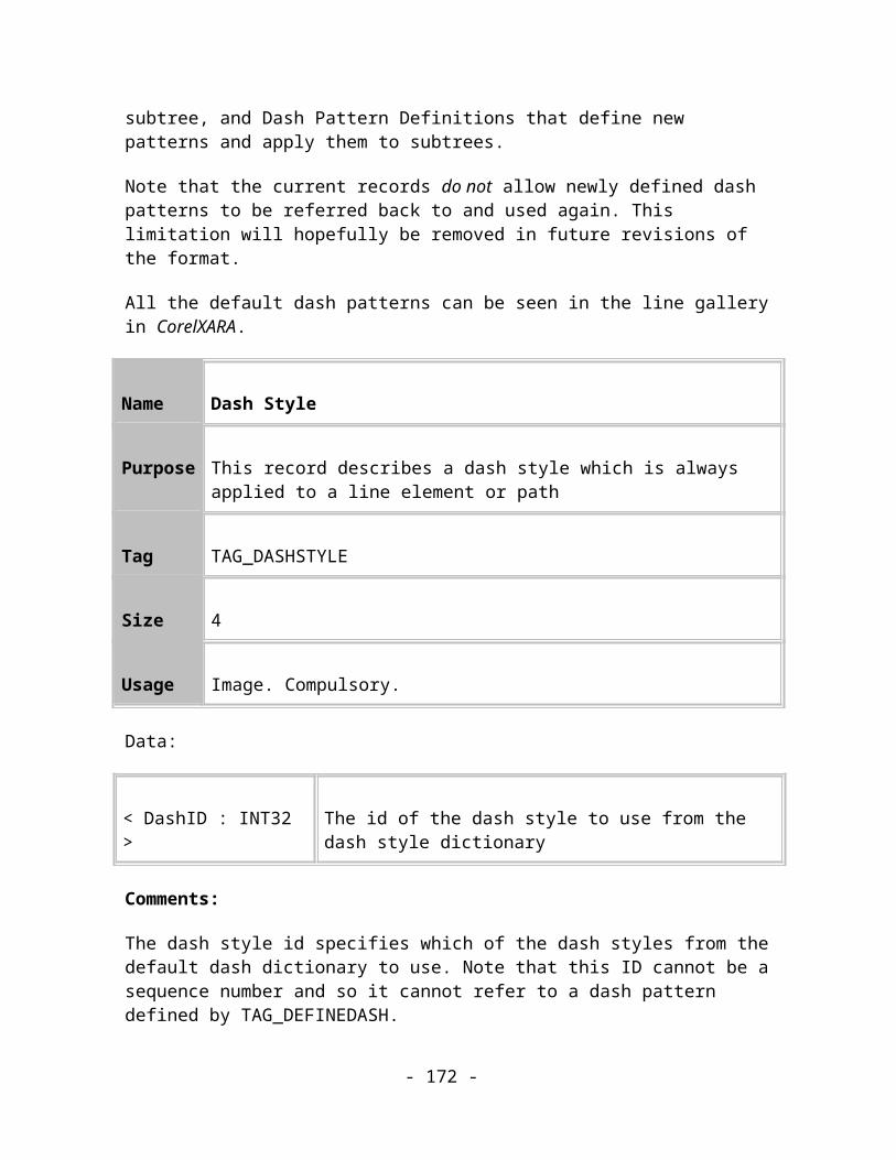
The curve point (if the shape has primary curvature)
The stellation point (if the shape is stellated)
The stellation curve points (if the shape is stellated and has stellation curvature)
The following curve point (if the shape has primary curvature)
Figure 10.11. Constructing a path for a stellated, rounded, reformed QuickShape.
If the shape is rounded then draw the curves at the corners.
If the shape isn’t reformed then draw straight lines between the corner points, stellation points or curve points as appropriate.
If the shape is reformed then transform the Edge Paths to fit between the corner points, stellation points or curve points as appropriate and draw them.
This renderable path is then transformed by the shape’s transformation matrix.
- 172 -

BlendsOverview
Blends are a way or “morphing” one shape into another – a number of intermediate shapes are generated which change gradually from the first shape to the second. A blend is defined by a set of one or more source objects, a set of one or more destination objects, the number of blending steps between source and destination and some control information. Give this information the blending process then blends the set of source objects into the set of destination objects in terms of both shape and colour. The illustration below shows a simple blend:
Figure 11.1. A blend from a light blue circle to a magenta rectangle in 5 steps.
The in-between steps are not stored in the Xar format, but are calculated when the objects are first loaded or when they’re rendered.
On renderers that support anti-aliasing, the intermediate objects can be instructed not to anti-alias. Anti-aliasing can be a slow process and since the colour of an intermediate object is likely to be very similar to the other intermediate objects around it, turning off anti-aliasing can speed up rendering with little loss of quality.
Colour changes in the blend steps can be specified in the same three variants as the fill attributes, so that the colours fade from one to another, use a rainbow effect or use an alternative rainbow effect.
The structure
A blend is made of several records arranged in a specific structure:
- 173 -
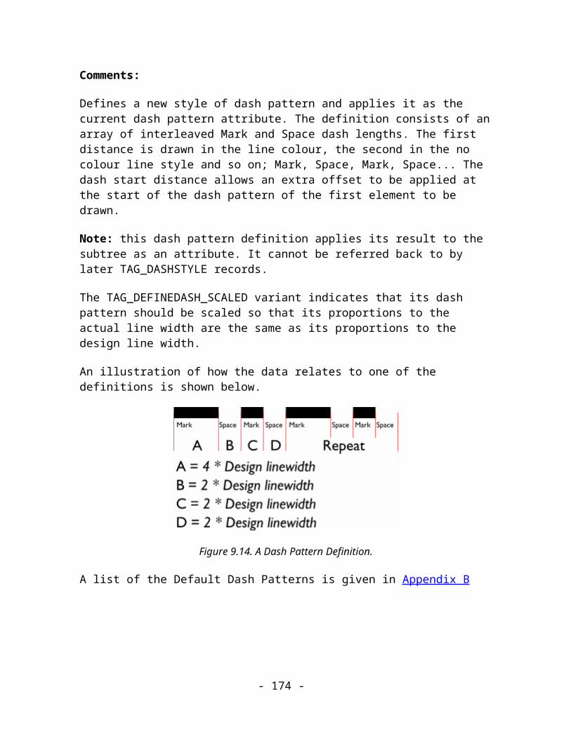
Figure 11.2. The basic record structure of a Blend.
Blend record
The ‘Blend’ record is like a group item and just acts as a container for all the records which compose the blend. The child records will consist of both the source and destination record sets and one or more Blender records which hold information such as the number of blend steps.
Blender record
The ‘Blender’ record is placed between the source and destination objects in the blend subtree. It contains the control information describing how the source should be blended to the destination.
Note that a Blend subtree can contain more than one Blender record. The Blender records are all placed between sets of object records – the destination set from one Blender becomes the Source set for the next. Tree structures like this are called ‘multi-stage blends’:
Figure 11.3. A multi-stage Blend.
- 174 -
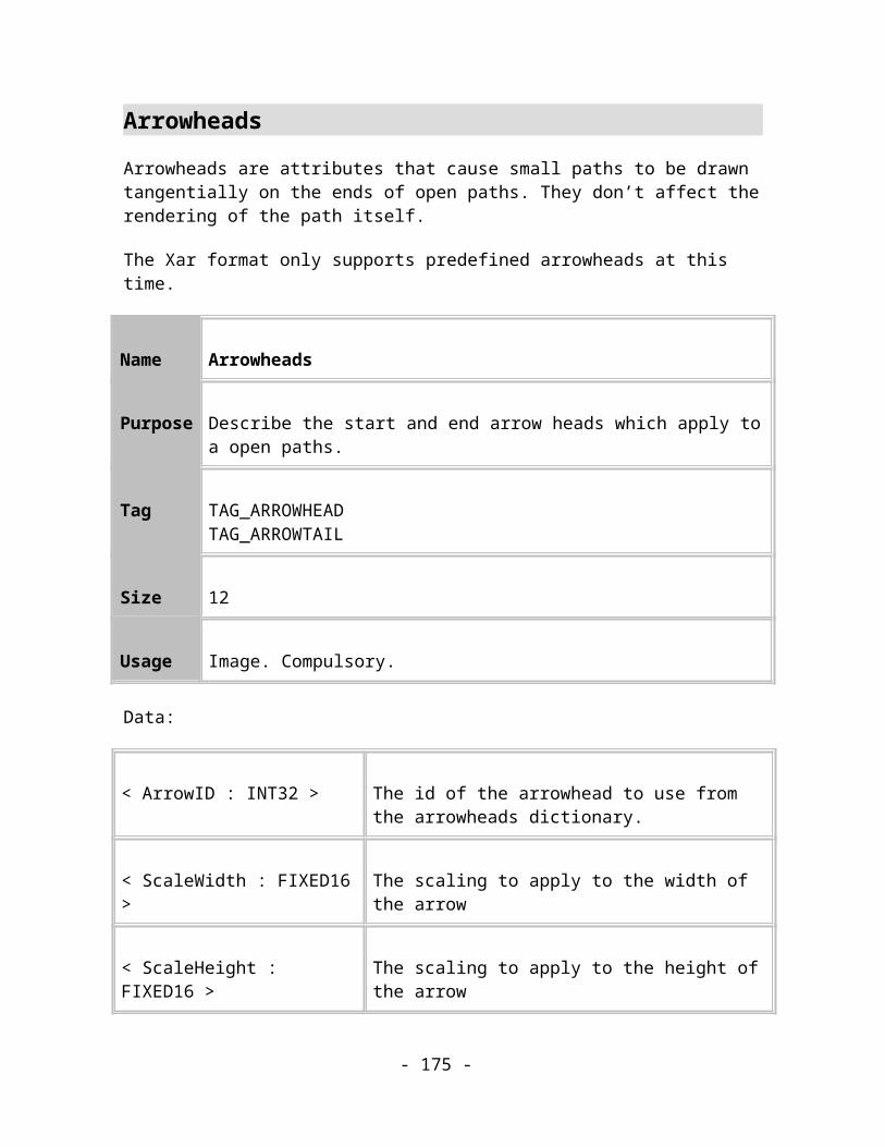
Name Blend
Purpose This record describes the blend grouping item
Tag TAG_BLEND
Size 3
Usage Image. Compulsory.
Data:
<Steps: UINT16> The number of intermediate steps rendered for each blend stage within the blend. This can be 0 when just the end objects are rendered
<Flags : BYTE>Bit field describing the following aspects of a blend
Bit 0 : OneToOne : Set if the blend should be done using a one-to-one mapping of the nodes in one path to the nodes of another path
Bit 1 : Antialiased : Set if the intermediate steps of the blend should be rendered anti-aliased
Bits 2 to 3 are reserved, and should be set to 0.
Bits 4-7 : ColourEffect: Describe the method in which colours should be blended.0 means Fade1 means Rainbow2 means Alternative Rainbow
Comments:
- 175 -
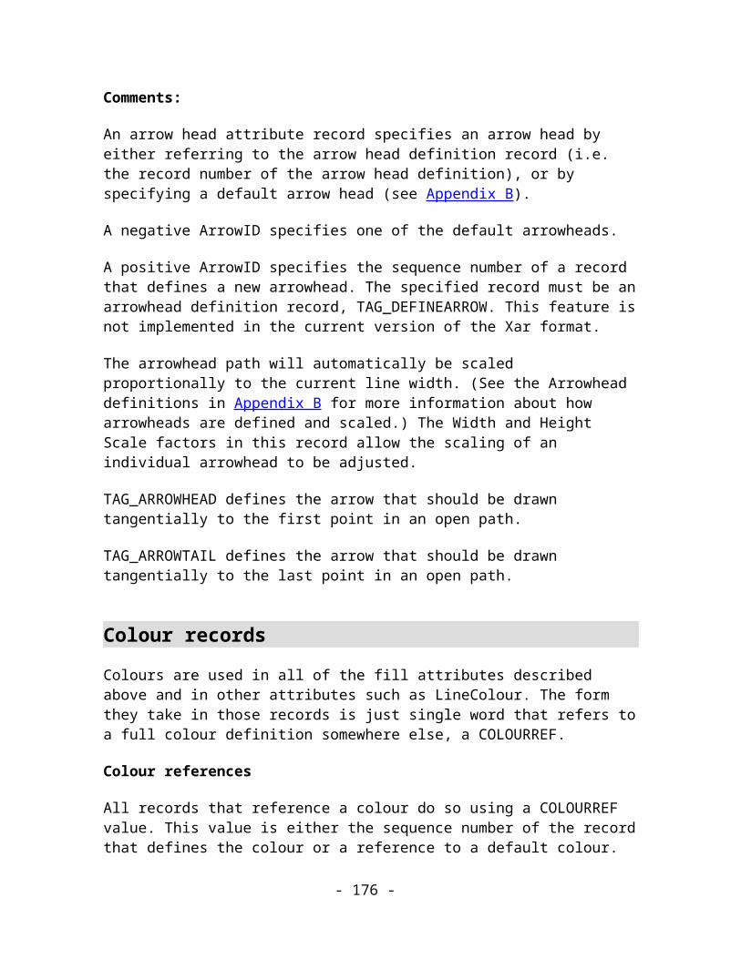
The record defines the head of a blend structure. The record forms the root of a sub-tree of records that make up the blend. All child records after this record are part of the blend object.
Name Blender
Purpose This record describes the blender item.
Tag TAG_BLENDER
Size 8
Usage Image. Compulsory.
Data:
<StartPathIndex : INT32> Mapping value for the path at the start of the blend. -1 (0xffffffff) means no mapping is specified.
<EndPathIndex : INT32> Mapping value for the path at the end of the blend. -1 (0xffffffff) means no mapping is specified.
Comments:
A Blender record controls the blending of the objects either side of it in the Xar file. The object record that precedes this record defines the path(s) at the start of the blend section. The object record that follows this record defines the path(s) at the end of the blend section.
The Blender record must have access to Path representations of the objects it is blending. If any object in the source or the destination sets of objects are not Paths then they must be converted into the equivalent paths before the Blender record is rendered.
For example, if the source object were a Rectangle, it would be converted to a single path that is visually identical to the rectangle. If the destination object were a line of text, it
- 176 -

would be converted to a series of paths that look exactly like the original text. The blender would then blend the path representing the rectangle to the set of paths representing the text.
Figure 11.4. The effect of blending a rectangle to a line of text.
Mapping Values
The mapping value defines a specific point in the path to start blending from. It is an index into the path’s list of co-ordinates. The blend then occurs as if the path’s first co-ordinate was the one at this index.
A mapping value of (-1) is defined as the index of the bottom-left most co-ordinate. This allows different paths (i.e. paths with different sets of co-ordinates) to be blended together more successfully.
The StartPathIndex & EndPathIndex fields can only have values other than (-1) if both the source and the destination object sets of the blend consist of exactly one path each.
Name Blender Additional
Purpose This record holds more properties of the blender item.
Tag TAG_BLENDERADDITIONAL
Size 17
- 177 -

Usage Image. Compulsory.
Data:
<BlendOnPath : INT32> Flag for blend on a path.
<BlendPathIndex : INT32> Index of something to do with blending on a curve.
<StartObjectIndex : INT32> Index of start object.
<EndObjectIndex : INT32> Index of end object.
<BlenderFlags : BYTE> Some flags.
Comments:
This record, if present, immediately follows the Blender record. The ObjectIndex values are relative to the parent bland record indicating which object the blend references. E.g. If StartObjectIndex = 2, then the start object that the blender will blend is the third renderable object record (starting from the first child) under the parent Blend record.
Name Blend Profiles
Purpose This record holds the object and attribute profiles of the blend.
Tag TAG_BLENDPROFILES
Size 24
- 178 -

Usage Image. Compulsory.
Data:
<ObjectProfile : PROFILE> The profile of the object positions.
<AttributeProfile : PROFILE> The profile used to blend the attributes.
Comments:
This record allow the object spacing and attribute blending to be controlled. It appears immediately before the bland record that it refers to.
Name Blender Curve Properties
Purpose This record holds the curve position properties of the blend.
Tag TAG_BLENDER_CURVEPROP
Size 16
Usage Image. Compulsory.
Data:
<StartPosition : DOUBLE> The position of the start object on the curve as a value from 0.0 to 1.0
<EndPosition : DOUBLE> The position of the end object on the curve as a value
- 179 -

from 0.0 to 1.0
Comments:
This record appears as a child of the Blender record.
Name Blend Path
Purpose This record holds the path the blend follows.
Tag TAG_BLEND_PATH
Size Variable
Usage Image. Compulsory.
Data:
The data section for this record is identical to a standard path record.
Name Blend Path Filled
Purpose This record holds the curve position properties of the blend.
Tag TAG_NODEBLENDPATH_FILLED
Size 16
- 180 -
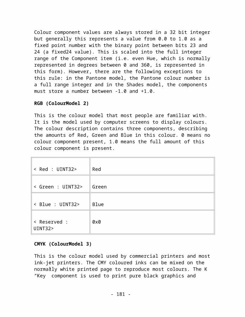
Usage Image. Compulsory.
Data:
<Filled : INT32> Flag to indicate that the blend path should be filled.
Comments:
This record, if present, appears immediately after the blend path record.
Name Blender Curve Angles
Purpose This record holds the angles of the start and end objects.
Tag TAG_BLENDER_CURVEANGLES
Size 16
Usage Image. Compulsory.
Data:
<StartAngle : DOUBLE> The angle of the start object in degrees.
<EndAngle : DOUBLE> The angle of the end object in degrees.
Comments:
This record appears as a child of the Blender record. It is only present if one or both of the angles are not zero.
- 181 -
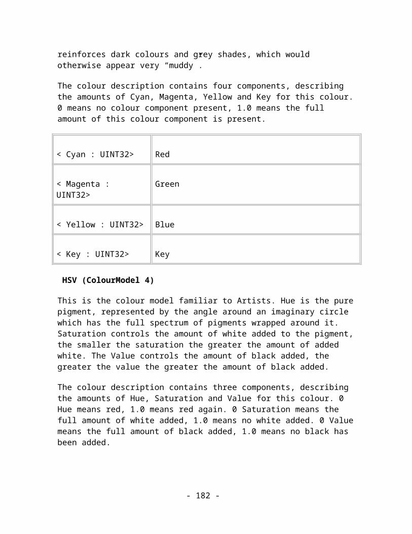
Blending
To display this data accurately you need to know the appropriate algorithm. This algorithm is not supplied in this release of the Xar format specification. However, it is a commonly-used algorithm in many Illustration packages.
- 182 -

MouldsOverview
Moulds are records which change the shapes of objects in some way. At present only two types of moulds are defined, 4-point Envelopes and Perspectives. 4-point Envelopes warp or distort the objects so that they fit within an envelope shape defined by 4 Bezier segments. Perspective envelopes distort the objects according to the rules of perspective drawing so that they look as if they’ve been tilted back into the picture.
All moulds work in the same way: they take objects and apply a complex transformation to the object’s co-ordinates. The transformed objects are then displayed in the drawing. The mould transformation is based upon the mould shape and the bounding rectangle enclosing all the moulded objects. It may clip co-ordinates so that they are well behaved.
The structure
The tree structure associated with a mould is shown below: -
Figure 12.1. The basic record structure of a Mould.
- 183 -
Mould
The ‘Mould’ record is like a group record and acts as a container for all of the records that form a mould. The records that make a complete mould are: the records that the user has selected to be warped, the shape of the mould, some control information and, optionally, the moulded versions of the objects. The Mould record will actually be either TAG_MOULD_ENVELOPE or TAG_MOULD_PERSPECTIVE.
Mould Path
The ‘Mould Path’ record is the shape that controls the warping space. It is this shape which is presented to the user as “the mould” and editors may allow the shape to be edited. It is just a normal path, but different classes of mould may put restrictions on the format of the path. For instance, the Perspective mould must have a Mould Path consisting of a closed shape of 4 straight lines.
Mould Group
The ‘Mould Group’ record is another container. This one holds all of the unmoulded objects, the source objects, and their attributes.
Moulder
The ‘Moulder’ record is yet another container record, holding the moulded versions of objects and attributes within the ‘Mould Group’.
NOTE! The ‘Moulder’ record and it’s subtree are NOT saved in the Xar format. It is described here because it is generated when the Source objects are moulded, usually when the file is first loaded into memory. The moulded objects are added to the tree structure inside the ‘Moulder’ record so that they take part in rendering properly.
Name Envelope Mould
Purpose This record describes the envelope mould grouping item
Tag TAG_MOULD_ENVELOPE
- 184 -

Size 4
Usage Image. Compulsory.
Data:
<ErrorThreshold : UINT32>
A value that controls the accuracy of the moulded curves. The smaller the value, the more accurate the mould will be. (Should be greater than 32 – typical value is 128)
Comments:
This record acts just like a simple group item and contains all of the objects that are needed to define the envelope and the objects which are being enveloped.
Figure 12.2 A graphic and an envelope moulded version of it.
Name Perspective Mould
Purpose This record describes the perspective mould grouping item
Tag TAG_MOULD_PERSPECTIVE
Size 4
- 185 -

Usage Image. Compulsory.
Data:
<ErrorThreshold : UINT32>
A value that controls the accuracy of the moulded curves. The smaller the value, the more accurate the mould will be. (Should be greater than 32 – typical value is 128)
Comments:
This record acts just like a simple group item and contains all of the objects that are needed to define the Perspective and the objects that are being Perspectivised.
Figure 12.3. A graphic and a perspective moulded version of it.
Name Mould Path
Purpose This record describes the mould path
Tag TAG_MOULD_PATH
Size Variable.
- 186 -

Usage Image. Compulsory.
Data:
< MouldPath : PATH > The path which describes the mould (see TAG_PATH)
Comments:
This record describes the path that defines the moulding space that the particular form of mould operation then needs to apply to all the unmoulded objects.
Name Mould Bounds
Purpose This record holds the bounding rectangle of the source objects
Tag TAG_MOULD_BOUNDS
Size 16
Usage Image. Optional.
Data:
< BottomLeft : COORD >
The bottom left corner of the bounding rectangle
< TopRight : COORD > The top right corner of the bounding rectangle
Comments:
- 187 -

The moulding algorithms need to know the bounding rectangle of the original objects to perform the necessary transformation. The presence of this record allows a renderer to start rendering the moulded objects before all of the source objects have been loaded.
Name Mould Group
Purpose This record describes the mould grouping item which contains the unmoulded objects.
Tag TAG_MOULD_GROUP
Size 0
Usage Image. Compulsory.
Comments:
This record acts just like a simple group item and contains all of the objects that are the unmoulded objects. It is always found inside the main mould group, at present either an envelope or a perspective mould.
Envelope Mould Algorithm
To display this data accurately you need to know the appropriate algorithm. This algorithm is not supplied in this release of the Xar format.
In it simplest form, the envelope warping might be thought of in its starting, or untransformed state, as a simple rectangle the same size as the bounds of the objects to be warped. This rectangle can be thought of as a piece of rubber paper, which can be stretched, without tearing, into the warped space. It is bounded by the warping path, which the user can edit to change what the piece of paper looks like.
- 188 -

Perspective Mould Algorithm
To display this data accurately you need to know the appropriate algorithm. This algorithm is not supplied in this release of the Xar format.
- 189 -

BevelsA bevelled object consists of a TAG_BEVEL record which acts as a simple group object. The children of this record will be any attributes that are common to both the original object(s) and the bevel, then the TAG_BEVELINK record representing the bevel itself complete with the attributes applied to the bevel as its children and then the original object being bevelled.
Name Bevel
Purpose This record represents a bevelled object.
Tag TAG_BEVEL
Size 24
Usage Image, Compulsory
Data:
<Type : INT32> The type of the bevel
<Indent : MILLIPOINT>
The size of the bevel
<LightAngle : INT32> The lighting angle (degrees). 0 degrees means the object is lit from the right and 90 degrees means the object is lit from below.
<Flags : INT32> Bit 0 – if set then outer bevel otherwise inner bevelBits 1-31 – Reserved. Must be 0
<Contrast : INT32> The contrast value of the bevel from 0 to 100
- 190 -
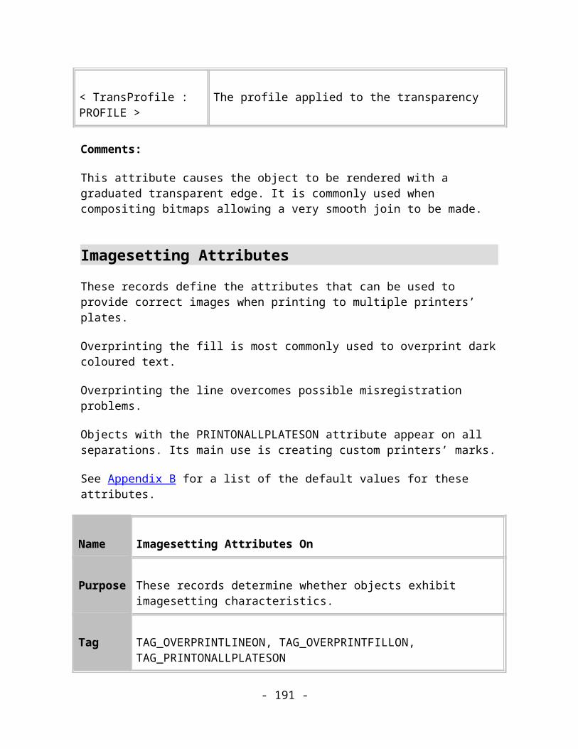
<Tilt : INT32> The light elevation of the bevel (degrees). 0 degrees means the object is lit “horizontally” and 90 degrees means the object is lit from straight “above”.
Comments:
This record acts just like a simple group item and contains all of the objects that are needed to define the bevel and the objects which are being bevelled.
Bevel Type
The bevel type controls the “shape” of the bevel. The currently defined values are shown in the table below.
Bevel Type Description Example
0 Flat
1 Round Frame
2 Round Frame 2
- 191 -

3 Flat Top Frame
4 Chiselled
5 Chiselled 2
6 Rounded
7 Rounded 2
8 Point Frame 1
- 192 -

9 Point Frame 2
10 Point Frame 3
11 Ruffle Frame 1
12 Ruffle Frame 2
13 Ruffle Frame 3
14 Ruffle Frame 4
- 193 -

Name Bevel Ink
Purpose This record represents the bevel.
Tag TAG_BEVELINK
Size 0
Usage Image, Compulsory
Comments:
This record represents the bevel itself. Any attributes applied to the bevel will be children of this record.
- 194 -

ContoursContours let you create interesting effects around the edges of objects. It creates a number of concentric objects either inside or outside the object(s) being contoured. The attributes of the outermost contour object can be controlled and the intermediate contour steps will blend between them and the attributes of the main object. The intermediate steps can aso be hidden (InsetPath) which has the effect of shrinking or expanding the original object in a different way to simply scaling the object.
A contoured object consists of a TAG_CONTOURCONTROLLER record which acts as a simple group object. The children of this record will be any attributes that are common to both the original object(s) and the contour, then the TAG_CONTOUR record representing the most extreme contour step complete with the attributes applied to the contour as its children and then the original objects being contoured. If there is more than one 195ezier195l object then the contours are generated as if the original objects’ paths are added together.
Name Contour Controller
Purpose This record represents a contoured object.
Tag TAG_CONTOURCONTROLLER
Size 41
Usage Image, Compulsory
Data:
<Steps : INT32> The number of contour steps to generate. This will be one less than the value displayed by XaraX¹
<Width : MILLIPOINT>
The width of the contour. A positive value indicates an inner contour and a negative value indicates an outer contour
- 195 -
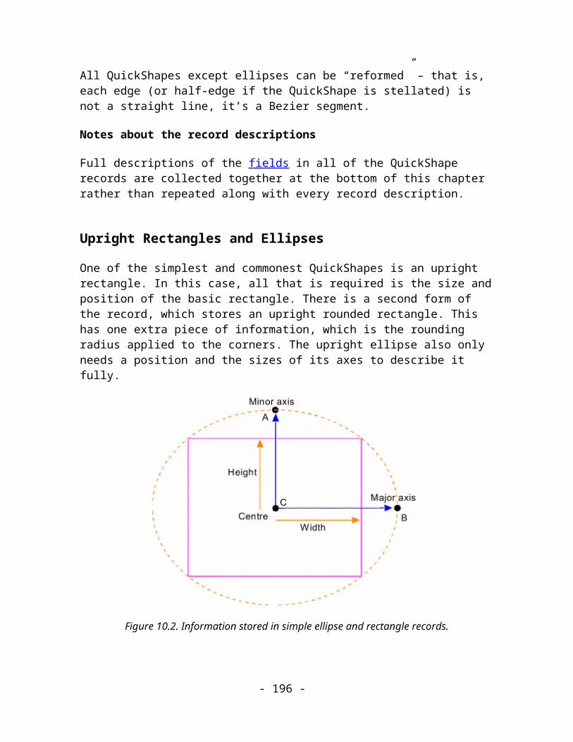
<Type : BYTE>Bit field describing the following aspects of a contour
Bits 0-1 : ColourEffect: Describe the method in which colours should be blended.0 means Fade1 means Rainbow2 means Alternative Rainbow
Bits 2-6 are reserved, and should be set to 0.
Bit 7 : InsetPath: This hides the intermediate contour steps.
<PositionProfile : PROFILE>
The position profile controlling the spacing of the steps
<AttributeProfile : PROFILE>
The attribute profile controlling the transition of the attributes
Comments:
This record acts just like a simple group item and contains all of the objects that are needed to define the contour and the objects which are being contoured.
Name Contour
Purpose This record represents a contoured object.
Tag TAG_CONTOUR
Size 0
Usage Image, Compulsory
Comments:
- 196 -

This record represents the most extreme contour object. The attributes applied to the contour will be children of this record.
- 197 -

ShadowsA shadowed object consists of a TAG_SHADOWCONTROLLER record which acts as a simple group object. The children of this record will be any attributes that are common to both the original object(s) and the shadow, then the TAG_SHADOW record representing the shadow itself complete with the attributes applied to the shadow as its children and then the original object being shadowed. Only one object can be shadowed but multiple objects can be grouped together so they are treated as one object.
Name Shadow Controller
Purpose This record represents an object with a shadow.
Tag TAG_SHADOWCONTROLLER
Size 29
Usage Image, Compulsory
Data:
<Type : BYTE> The type of shadow. 1 – wall shadow, 2 – floor shadow, 3 – glow shadow
<PenumbraWidth : MILLIPOINT>
The width of the shadow blur.
<ShadowOffset : COORD>
The offset of the wall shadow
<FloorAngle : LONG> The angle of the floor shadow in radians multiplied by 1000000. Must be between -2*PI and 2*PI
- 198 -
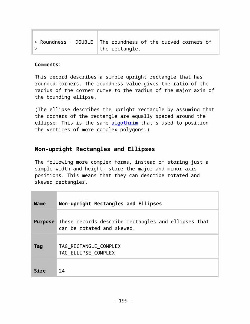
<FloorHeight : LONG>
The height of the floor shadow relative to the original object multiplied by 100
<WallScale : LONG> The scale factor of the wall shadow multiplied by 100
<GlowWidth : MILLIPOINT>
The width of the glow shadow
Comments:
This record acts just like a simple group item and contains all of the objects that are needed to define the shadow and the objects which are being shadowed.
Name Shadow
Purpose This record represents the shadow itself.
Tag TAG_SHADOW
Size 24
Usage Image, Compulsory
Data:
<Profile : PROFILE> The shadow’s profile controlling the transparency transition
<Darkness : DOUBLE>
The darkness value of the shadow. 0.0 – totally transparent, 1.0 – totally opaque
- 199 -

Comments:
This record represents the shadow itself. The attributes applied to the shadow (e.g. the shadow colour) will be children of this record.
- 200 -
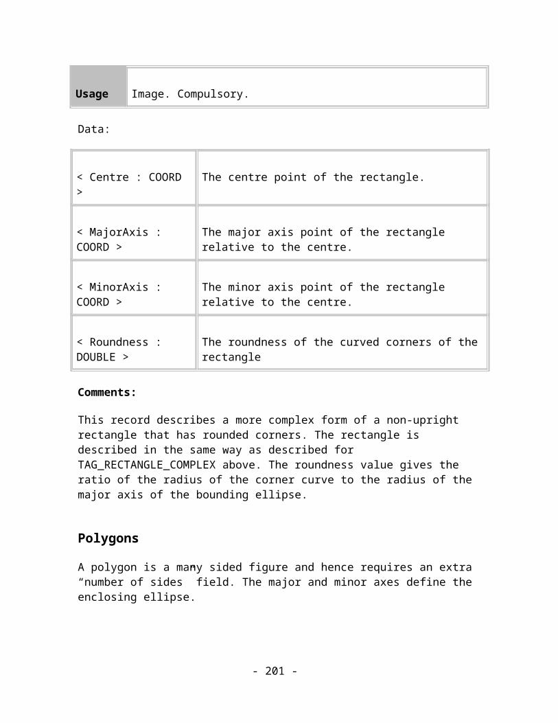
BrushesA brush is a collection of objects that are rendered along a path. This allows the creation of realistic looking artistic materials (e.g. chalk, airbrush etc.) and almost anything else that can be repeated along a curve (e.g. chain links, footprints etc.). The spacing, scaling, distance from the curve, transparency and many other properties can be altered or made to change randomly along the curve allowing a very wide range of effects to be achieved.
Brushes support pressure sensitivity allowing one or more of the properties (scaling, spacing, transparency etc.) to vary according to the pressure sample data which is usually collected from a pressure sensitive tablet.
Name Brush Definition
Purpose This record defines a brush.
Tag TAG_BRUSHDEFINITION
Size 4
Usage Image, Compulsory
Data:
<Handle : UINT32> The handle of this brush.
Comments:
The objects that make up the brush are children of this record.
Name Brush Data
- 201 -

Purpose This record holds various properties of a brush.
Tag TAG_BRUSHDATA
Size Variable
Usage Image, Compulsory
Data:
<Handle : UINT32> The handle of this brush.
<Spacing : MILLIPOINT> The spacing of this brush.
<Flags : BYTE> Flags for this brush.
<RotateAngle : DOUBLE> The rotation angle of this brush.
<OffsetType : INT32> The offset type of this brush (0 – none, 1 – alternate, 2 – left, 3 – right, 4 – random).
<PathOffset : MILLIPOINT> The handle of this brush.
<Name : STRING> The name of this brush.
<Scaling : DOUBLE> The scaling of this brush.
Comments:
This record holds some of the properties of the brush.
- 202 -

Name More Brush Data
Purpose This record holds more properties of a brush.
Tag TAG_MOREBRUSHDATA
Size 68
Usage Image, Compulsory
Data:
<ProportionalSpacingIncrement : DOUBLE>
The proportional spacing increment of this brush.
<ConstantSpacingIncrement : MILLIPOINT>
The constant spacing increment of this brush.
<SpacingMax : MILLIPOINT> The maximum value for random spacing.
<SpacingSeed : INT32> The seed value for random spacing.
<ScalingIncrement : DOUBLE> The scaling increment of this brush.
<ScalingMax : INT32> The maximum value for random scaling.
<ScalingSeed : INT32> The seed value for random scaling.
<SequenceType : INT32> The sequence type of this brush.
- 203 -

<SequenceSeed : INT32> The seed value for random sequence.
<ProportionalPathOffsetIncrement : DOUBLE>
The proportional path offset increment of this brush.
<ConstantPathOffsetIncrement : LONG>
The constant path offset increment of this brush.
<OffsetTypeSeed : INT32> The seed value for random offset type.
<OffsetMax : MILLIPOINT> The maximum offset value of this brush.
<OffsetSeed : INT32> The seed value for random offset value.
Comments:
This record holds some more of the properties of the brush.
Name Even More Brush Data
Purpose This record hold even more properties of a brush.
Tag TAG_EVENMOREBRUSHDATA
Size 8
Usage Image, Compulsory
Data:
- 204 -

<RotationMax : INT32> The maximum value for random rotation.
<RotationSeed : INT32> The seed value for random rotation.
Comments:
This record holds some more of the properties of the brush.
Name Brush Pressure Info
Purpose This record hold pressure information of a brush.
Tag TAG_BRUSHPRESSUREINFO
Size 28
Usage Image, Compulsory
Data:
<ScalingMax : INT32> The extent to which pressure affects scaling.
<SpacingMax : INT32> The extent to which pressure affects spacing.
<OffsetMax : INT32> The extent to which pressure affects offset.
<RotationMax : INT32> The extent to which pressure affects rotation.
- 205 -
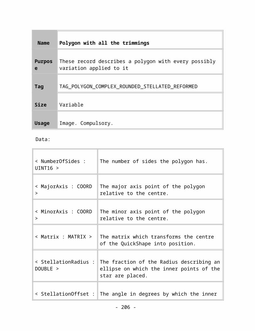
<HueMax : INT32> The extent to which pressure affects hue.
<SaturationMax : INT32> The extent to which pressure affects saturation.
<TimestampMax : INT32> The extent to which pressure affects timestamping.
Comments:
This record specifies the amount that pressure affects various properties of the brush.
Name Brush Transparency Info
Purpose This record holds transparency information of a brush.
Tag TAG_BRUSHTRANSPINFO
Size 40
Usage Image, Compulsory
Data:
<Transparency : INT32> The transparency of the brush.
<TranspMaxPressure : INT32> The extent to which pressure affects transparency.
<ConstantRotationIncrement : DOUBLE>
The constant rotation increment.
- 206 -

<ConstantScalingIncrement : DOUBLE>
The constant scaling increment.
<HueMax : INT32> The maximum value for random hue.
<SaturationMax : INT32> The seed value for random hue.
<SaturationMax : INT32> The maximum value for random saturation.
<TimestampMax : INT32> The seed value for random saturation.
Comments:
This record specifies the amount that pressure affects various properties of the brush.
Name Brush Attribute
Purpose This record applies a brush to an object.
Tag TAG_BRUSHATTR
Size 33
Usage Image, Compulsory
Data:
<Handle : UINT32> The handle of the brush applied.
- 207 -

<Spacing : MILLIPOINT> The spacing of this brush.
<Flags : BYTE> Flags for this brush.
<RotateAngle : DOUBLE> The rotation angle of this brush.
<Offset : MILLIPOINT> The offset of this brush.
<PathOffset : MILLIPOINT> The handle of this brush.
<Scaling : DOUBLE> The scaling of this brush.
Comments:
This record holds some of the properties of the brush attribute.
Name More Brush Attribute Data
Purpose This record holds more properties of a brush attribute.
Tag TAG_MOREBRUSHATTR
Size 72
Usage Image, Compulsory
Data:
- 208 -

<ProportionalSpacingIncrement : DOUBLE>
The proportional spacing increment of this brush.
<ConstantSpacingIncrement : MILLIPOINT>
The constant spacing increment of this brush.
<SpacingMax : MILLIPOINT> The maximum value for random spacing.
<SpacingSeed : INT32> The seed value for random spacing.
<ScalingIncrement : DOUBLE> The scaling increment of this brush.
<ScalingMax : INT32> The maximum value for random scaling.
<ScalingSeed : INT32> The seed value for random scaling.
<SequenceType : INT32> The sequence type of this brush.
<SequenceSeed : INT32> The seed value for random sequence.
<ProportionalPathOffsetIncrement : DOUBLE>
The proportional path offset increment of this brush.
<ConstantPathOffsetIncrement : LONG>
The constant path offset increment of this brush.
<OffsetTypeSeed : INT32> The seed value for random offset type.
<OffsetMax : MILLIPOINT> The maximum offset value of this brush.
<OffsetSeed : INT32> The seed value for random offset value.
- 209 -

<LocalFill : INT32> If non-zero then use the local fill colour else use the colours in the brush.
Comments:
This record holds some more of the properties of the brush.
Name Even More Brush Attribute Data
Purpose This record hold even more properties of a brush attribute.
Tag TAG_EVENMOREBRUSHATTR
Size 9
Usage Image, Compulsory
Data:
<RotationMax : INT32> The maximum value for random rotation.
<RotationSeed : INT32> The seed value for random rotation.
<Flags : BYTE> Flags for the brush. Bit 0 – Scale to width
Comments:
This record holds some more of the properties of the brush.
- 210 -

Name Brush Attribute Fill Flags
Purpose This record controls how the fills of the brush behave.
Tag TAG_BRUSHATTRFILLFLAGS
Size 1
Usage Image, Compulsory
Data:
<Flags : BYTE> Flags controlling the fill of the brush.
Comments:
This record holds flags controlling how the fills of the brush behave.
Name Brush Attribute Pressure Info
Purpose This record hold pressure information of a brush attribute.
Tag TAG_BRUSHATTRPRESSUREINFO
Size 28
Usage Image, Compulsory
Data:
- 211 -

<ScalingMax : INT32> The extent to which pressure affects scaling.
<SpacingMax : INT32> The extent to which pressure affects spacing.
<OffsetMax : INT32> The extent to which pressure affects offset.
<RotationMax : INT32> The extent to which pressure affects rotation.
<HueMax : INT32> The extent to which pressure affects hue.
<SaturationMax : INT32> The extent to which pressure affects saturation.
<TimestampMax : INT32> The extent to which pressure affects timestamping.
Comments:
This record specifies the amount that pressure affects various properties of the brush.
Name Brush Attribute Transparency Info
Purpose This record holds transparency information of a brush.
Tag TAG_BRUSHATTRTRANSPINFO
Size 40
Usage Image, Compulsory
Data:
- 212 -

<Transparency : INT32> The transparency of the brush.
<TranspMaxPressure : INT32> The extent to which pressure affects transparency.
<ConstantRotationIncrement : DOUBLE>
The constant rotation increment.
<ConstantScalingIncrement : DOUBLE>
The constant scaling increment.
<HueMax : INT32> The maximum value for random hue.
<SaturationMax : INT32> The seed value for random hue.
<SaturationMax : INT32> The maximum value for random saturation.
<TimestampMax : INT32> The seed value for random saturation.
Comments:
This record specifies the amount that pressure affects various properties of the brush.
Name Brush Timestamp Data
Purpose This record holds timestamped brush positions.
Tag TAG_TIMESTAMPBRUSHDATA
Size Variable
- 213 -
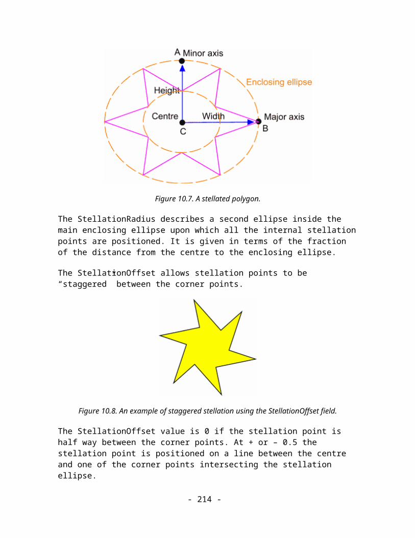
Usage Image, Compulsory
Data:
<Count : INT32> The number of brush points in this record. The following 4 data items are repeated this many times.
<Point : COORD> Th position of the sample point.
<Tangent : DOUBLE> The tangent to the curve at this point.
<ProportionalDistance : DOUBLE>
The distance along the curve as a value from 0.0 to 1.0.
<Distance : MILLIPOINT> The distance along the curve in millipoints.
Comments:
This record holds a list of points and tangent data for brush objects created by the timestamping method.
Name Brush Timestamp Data
Purpose This record holds the pressure data samples.
Tag TAG_BRUSHPRESSURESAMPLEDATA
Size Variable
- 214 -
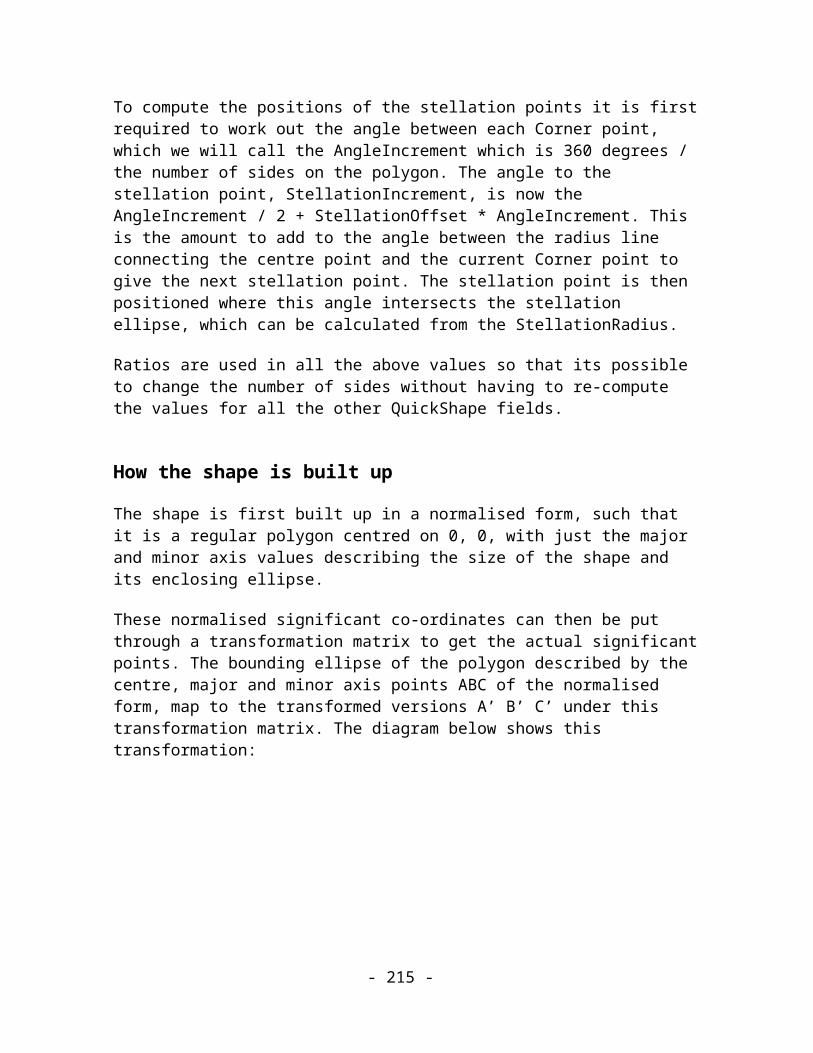
Usage Image, Compulsory
Data:
<Count : INT32> The number of samples in this record. The following 3 data items are repeated this many times.
<Pressure : INT32> The pressure value at the sample point.
<Point : COORD> The sample point.
<Distance : MILLIPOINT> The distance along the curve in millipoints.
Comments:
This record holds a list pressure samples at points along the curve.
Name Stroke Type Attribute
Purpose This defines the stroke type used to render the object.
Tag TAG_STROKETYPE
Size 4
Usage Image, Compulsory
Data:
- 215 -
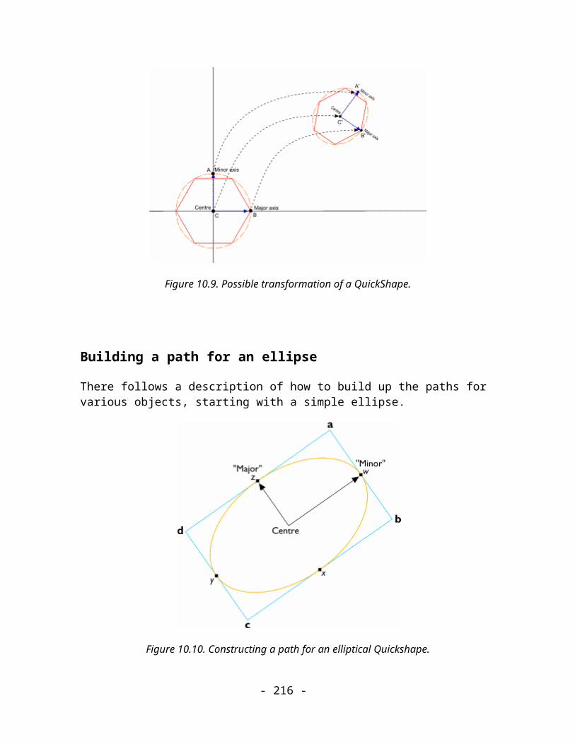
<Handle : UINT32> The handle of the stroke type. Currently this should only be set to 0x01000000 to indicate a simple (i.e. constant width) stroke or to 0x02000000 to indicate a variable width stroke (defined by a TAG_VARIABLEWIDTHTABLE record).
Comments:
This record sets the type of stroke to render the object with.
Name Variable Width Definition
Purpose This record defines a variable stroke width profile.
Tag TAG_VARIABLEWIDTHTABLE
Size Variable
Usage Image, Compulsory
Data:
<Type : UINT32> The type of the profile.
<Type Specific Data> Data specific to the particular type of profile.
Comments:
This record defines a variable width profile. The profiles define a mapping function that maps values in the range 0.0 to 1.0 representing distance along the path to a value between -1.0 and 1.0 representing the line width (as a scaling of the applied line width) at that point of the path.
- 216 -

There are many different types and they are grouped into the following main types depending on what extra data is required in the record to define the profile.
Type Type Name Data Details
1 Constant <Value : FLOAT> This is a constant value.
2 Random <Seed : UINT32><Min : FLOAT><Max : FLOAT>
This generates a table of 512 pseudorandom integers between 0 and 0xffff using the seed value and then linearly interpolates between two of them to get a value in the range 0 to 0xffff. This is then mapped onto the range Min to Max.
3 RampLinear <Value1 : FLOAT><Value2 : FLOAT>
This is a simple linear interpolation between Value1 and Value2
4 RampS <Value1 : FLOAT><Value2 : FLOAT>
This is a linear interpolation between Value1 and Value2 using the following expression to generate the mix value: (cos(Input * Pi) + 1.0) / 2.0
5 Pressure <Count : UINT32><Position : UINT16><Pressure : UINT16>
The Position and Pressure items are repeated Count times. Both the Position and Pressure values represent values in the range 0.0 to 1.0 (e.g.
- 217 -

divide by 65535). This linearly interpolates between the two closest pressure points in the array.
6 PressureS <Count : UINT32><Position : UINT16><Pressure : UINT16>
The Position and Pressure items are repeated Count times. Both the Position and Pressure values represent values in the range 0.0 to 1.0 (e.g. divide by 65535). This interpolates between the two closest pressure points in the array using the following mapping:In first and last segment: cos(-MixValue * (Pi / 2.0))Otherwise: (cos(MixValue * Pi) + 1.0) / 2.0where MixValue is the proportional distance of the input value between the two closest pressure points
7 Teardrop <MaxPos : FLOAT> This uses the following mapping:If Input < MaxPos then cos(asin(1.0 – (Input / MaxPos)))Otherwise: (cos( Pi * (Input – MaxPos) / (1.0 – MaxPos)) + 1.0) / 2.0
8 Ellipse <MaxPos : FLOAT> This uses the following mapping:If Input < MaxPos then
- 218 -

cos(asin(1.0 – (Input / MaxPos)))Otherwise: cos(asin((Input – MaxPos) / (1.0 – MaxPos)))
9 Blip <MaxPos : FLOAT> This uses the following mapping:If Input < MaxPos then sin((Input / MaxPos) * (Pi / 2.0))Otherwise: cos((Pi / 2.0) * (Position – MaxPos) / (1.0 – MaxPos))
10 Thumbtack <MaxPos : FLOAT> This uses the following mapping:If Input < MaxPos then 1.0 – cos(asin(Input/MaxPos))Otherwise: 1.0 – cos(asin(1.0 – ((Input – MaxPos) / (1.0 – MaxPos))))
11 RampL <Value1 : FLOAT><Value2 : FLOAT>
This is a linear interpolation between Value1 and Value2 using the following expression to generate the mix value: cos((Pi/2.0) + (Input * Pi/2.0)) + 1.0
12 RampL2 <Value1 : FLOAT><Value2 : FLOAT>
This is a linear interpolation between Value1 and Value2 using the following expression to generate the mix value: cos((Pi/2.0) + (Position * Pi/2.0)) + 1.0
- 219 -

13 RampS2 <Value1 : FLOAT><Value2 : FLOAT>
This is a linear interpolation between Value1 and Value2 using the following expression to generate the mix value: (cos(Input * Pi) + 1.0) / 2.0
14 TeardropCurvedEnd <MaxPos : FLOAT> This uses the following mapping:If Input < MaxPos then cos(asin(1.0 – (Input / MaxPos)))Otherwise: sqrt(1.0 – ((Input – MaxPos) / (1.0 – MaxPos)))
15 SawTooth <Value1 : FLOAT><Value2 : FLOAT>
This uses the following mapping:If Input = 1.0 then 0.0Otherwise: 1.0 – ((9.0 * Input) – (floor(9.0 * Input)))²The parameters are ignored
16 Propeller <Value1 : FLOAT><Value2 : FLOAT>
This uses the following mapping:If Input < 0.15 then cos(asin(1.0 – (Input / 0.15)))If Input > 0.85 then cos(asin((Input – 0.85) / 0.15))Otherwise: (cos(2.0 * Pi * (Input – 0.15) / 0.7) + 1.5) * 0.4The parameters are ignored
- 220 -

17 DoubleRampS <Value1 : FLOAT><Value2 : FLOAT>
This is a linear interpolation between Value1 and Value2 using the following expression to generate the mix value: (cos(Input * 2.0 * Pi) + 1.5) * 0.4
18 Intestine <Value1 : FLOAT><Value2 : FLOAT>
This is a linear interpolation between Value1 and Value2 using the following expression to generate the mix value: ((cos(Position * 20.0 * Pi) + 3.0) / 4.0)
19 Decay <Value1 : FLOAT><Value2 : FLOAT>
This uses the following mapping: (1.0 – Input) * ((cos(Input * 20.0 * Pi) + 3.0) / 4.0)The parameters are ignored
20 BevelEnds <Value1 : FLOAT><Value2 : FLOAT>
This uses the following mapping:If Input = 1.0 then 0.0If Input < 0.15 then Input / 0.15If Input > 0.85 then (Input – 0.85) / 0.15Otherwise: 1.0The parameters are ignored
21-38 Bezier based <Value1y : FLOAT><Value2x : FLOAT><Value2y : FLOAT><Value3x : FLOAT><Value3y : FLOAT><Value4y : FLOAT>
All of these functions use a 221ezier curve based on the parameters to generate a table of input (x) and output (y) value pairs assuming that Value1x =
- 221 -
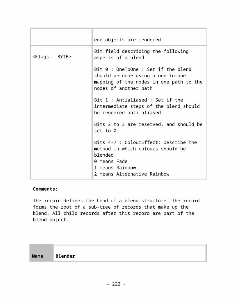
0.0 and Value4x = 1.0. This list of pairs is then searched to find the closest two points which are interpolated between. The parameter values must be as specified.
21 Reed Value1y = 0.0Value2x = 0.333Value2y = 1.0Value3x = 0.667Value3y = 0.5Value4y = 0.0
22 Meteor Value1y = 0.0Value2x = 0.15Value2y = 1.0Value3x = 0.667Value3y = 0.0Value4y = 0.0
23 Petal Value1y = 0.0Value2x = 0.15Value2y = 1.0Value3x = 0.3Value3y = 1.0Value4y = 0.0
24 Comet Value1y = 0.1Value2x = 0.05Value2y = 1.6Value3x = 0.15Value3y = 0.2Value4y = 0.05
25 Barb Value1y = 0.5Value2x = 0.333Value2y = 0.0
- 222 -

Value3x = 0.667Value3y = 1.0Value4y = 0.0
26 Concave Value1y = 1.0Value2x = 0.3Value2y = 0.2Value3x = 0.667Value3y = 0.15Value4y = 0.2
27 Convex Value1y = 1.0Value2x = 0.55Value2y = 1.3Value3x = 0.667Value3y = 0.4Value4y = 0.33
28 Iron Value1y = 1.0Value2x = 0.333Value2y = 1.0Value3x = 0.667Value3y = 1.0Value4y = 0.0
29 Torpedo Value1y = 1.0Value2x = 0.333Value2y = 0.5Value3x = 0.667Value3y = 1.0Value4y = 0.0
30 Missile Value1y = 1.0Value2x = 0.333Value2y = 0.0Value3x = 0.667Value3y = 1.0Value4y = 0.0
- 223 -

31 Goldfish Value1y = 0.5Value2x = 0.333Value2y = 0.0Value3x = 0.667Value3y = 1.0Value4y = 0.0
32 OceanLiner Value1y = 0.5Value2x = 0.333Value2y = 0.5Value3x = 0.667Value3y = 1.0Value4y = 0.0
33 Yacht Value1y = 0.5Value2x = 0.333Value2y = 1.0Value3x = 0.667Value3y = 1.0Value4y = 0.0
34 SlimBlip Value1y = 0.0Value2x = 0.15Value2y = 1.2Value3x = 0.85Value3y = 1.2Value4y = 0.0
35 Cigar Value1y = 0.4Value2x = 0.333Value2y = 1.3Value3x = 0.667Value3y = 1.3Value4y = 0.4
36 Cigar2 Value1y = 0.4Value2x = 0.333Value2y = 1.0Value3x = 0.667
- 224 -

Value3y = 1.0Value4y = 0.4
37 Cigar3 Value1y = 0.4Value2x = 0.333Value2y = 0.7Value3x = 0.667Value3y = 0.7Value4y = 0.4
38 Fallout Value1y = 1.0Value2x = 0.333Value2y = 1.0Value3x = 0.667Value3y = 1.0Value4y = 0.5
- 225 -

ClipViewA ClipView object consists of a TAG_CLIPVIEWCONTROLLER record which acts as a simple group object. The children of this record will be any attributes that are common to both the original object(s) and the clipping objects, then the clipping objects, then the TAG_CLIPVIEW record and then the original objects being clipped.
Name ClipView Controller
Purpose This record represents an object with a ClipView.
Tag TAG_CLIPVIEWCONTROLLER
Size 0
Usage Image, Compulsory
Comments:
This record acts just like a simple group item and contains all of the objects that are needed to define the ClipView and the objects which are being clipped.
Name ClipView
Purpose This record marks the end of the clipping path objects and the start of the objects to be clipped.
Tag TAG_CLIPVIEW
Size 0
- 226 -

Usage Image, Compulsory
Comments:
This record marks the end of the clipping path objects and the start of the objects to be clipped.
Name ClipViewPath
Purpose This record marks the end of the clipping path objects and the start of the objects to be clipped and also includes the actual path definition used to perform the clipping.
Tag TAG_CLIPVIEW_PATH
Size Variable
Usage Image, Optional
Data:
< ClipPath : PATH > The path to clip with (see TAG_PATH)
Comments:
This is a variant of the TAG_CLIPVIEW record that is only used when exporting to plugin filters that ask for it. It includes the actual path used to clip with when rendering the clip view to remove the need for the filter to generate the combined clipping path from the clipping objects and also to avoid problems with the conversion system changing the shape of the clipping objects (e.g. if one of the clipping objects gets converted into a bitmap then its path will become a simple rectangle which would give the wrong result if the filter were generating the clipping path).
- 227 -

Text
Overview
Xar format can encode text in several ways: single lines of text, blocks of text controlled by margins and text lines that follow a path. Any of the standard Attributes can be applied to any of the types of text, including all the fill types and transparency types. In addition to the normal Image Attributes, text objects have their own set of attributes, which control text formatting.
Text structure
A block of text, called a Text Story in Xar format, is built up of a list of Text Strings. Each String is an array of Unicode characters which all share the same attributes. So one of the rules that determines how a Text Story is broken up into Text Strings is based upon the position of attributes in the Text Story subtree. Another rule is determined by the position of Line End characters in the Story: a new Text String is always started after a Line End character.
Figure 13.1. The general structure of a Text
The Text Story record is a container for all the records that describes all the various aspects of a block of text. (The term Text Story comes from Desktop Publishing where a Story is a column of text which flows between frames and across pages). Text String records hold the basic text information – the runs of characters typed by the user.
Each character is uniquely represented by 2 bytes; a Unicode value. By using Unicode, Xar Writers don’t have to worry about the different character sets that exist on different versions of Windows or other platforms – they don’t have to target a particular platform. All possible characters are available in the Xar format and it’s up to the Readers to do their best to display them. Furthermore, Windows NT works entirely in Unicode and it is
- 228 -
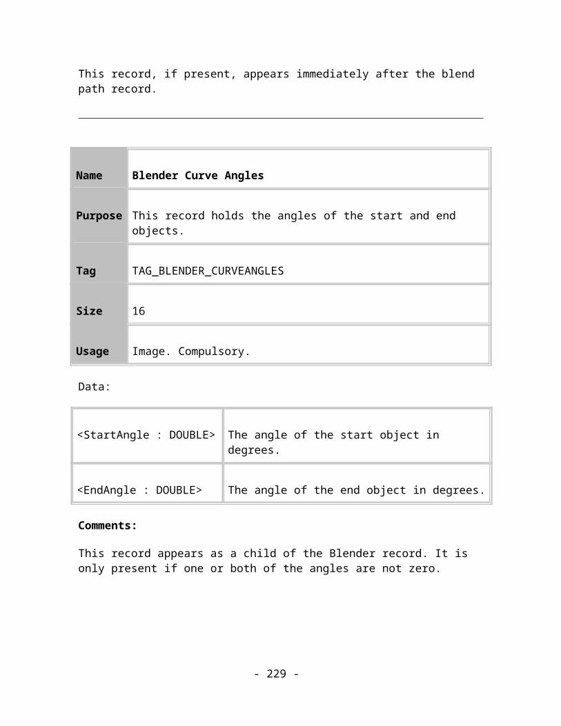
supported by Windows 95. CorelXARA works internally in Unicode. The Zlib compression layer deals with representing these two-bytes characters efficiently in the byte stream.
The Text String record holds a list of Unicode characters. CR characters (0xD) embedded in these strings imply a new line, so many lines of text can be represented by using one Text String record. Xar format only needs to use more than one Text String record for a block of text in the drawing if different attributes are applied to different areas of the text block (Figure 13.1).
Text structure records
In the descriptions that follow, the text is assumed to be upright; lines are described as being above and below each other. This is just a convenient way to think of blocks of text. It’s the most common case but text can be rotated to any angle. In that case the lines are no longer simply above and below each other but the same principles of relative positioning still apply.
Name Text story object
Purpose Parent object of the set of records that define a text story.
Tag TAG_TEXT_STORY_SIMPLE
Size 12 (8)
Usage Image. Compulsory.
Data:
< Anchor : COORD > Co-ordinate of anchor point of text.
< AutoKern : LONG >
Kerning flag. 0 – no kerning, 1 – automatic kerning.Note: this field may not be present in older Xar format documents
- 229 -

The anchor point of the text positions the text story in the document. In the most common case, when text is in English and the text is left aligned, the anchor point is the left-hand end of the baseline of the first line of text in the story.
Comments:
Starts a new text story subtree. This record should immediately be followed by a Down record; the end of the text story is indicated by an Up record.
This record represents text that hasn’t been rotated, sheared or reflected in any way.
The magnitude of any scale transformations that have been applied to the text are implicitly represented in the co-ordinates and dimension attributes (such as font size or line width) of the text story.
This text story is not fitted to a path. (See the section on Fitting Text to Paths for details of TEXT_STORY records that fit text to paths.)
Name Text story object
Purpose Parent object of the set of records that define a text story.
Tag TAG_TEXT_STORY_COMPLEX
Size 28 (24)
Usage Image. Compulsory.
Data:
< Transformation : MATRIX >
The transformation matrix describes the translation to move from 0,0 to the anchor point and also any rotation and shear that should be applied to the text.
- 230 -

< AutoKern : LONG >
Kerning flag. 0 – no kerning, 1 – automatic kerning.Note: this field may not be present in older Xar format documents
The anchor point of the text positions the text story in the document. In the most common case, when text is in English and the text is left aligned, the anchor point is the left-hand end of the baseline of the first line of text in the story.
Comments:
Starts a new text story subtree. This record should immediately be followed by a Down record; the end of the text story is indicated by an Up record.
The matrix describes any Rotations, Reflections or Shears that should be applied to the story.
The matrix does not describe Scales. The magnitude of any Scale transformations that have been applied to the text are implicitly represented in the co-ordinates and dimension attributes (such as font size or line width) of the text story.
This text story is not fitted to a path. (See the section on Fitting Text to Paths for details of TEXT_STORY records that fit text to paths.)
Name Text string
Purpose Holds a string of Unicode characters
Tag TAG_TEXT_STRING
Size Variable
Usage Image. Compulsory.
Data:
- 231 -
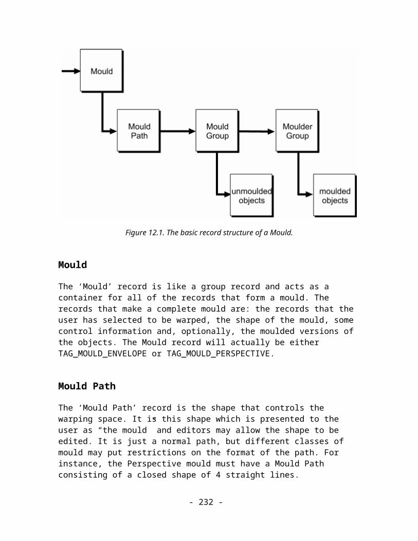
<Contents : n * UINT16>
Contents of string
Comments:
This record describes one of several possible sub-strings in a text story. The strings are added together in the order in which they appear in the Xar file to create the full story. Note: there is no terminator on this string, it is just a sequence of characters. The length is determined by the length of the record.
This record must be a child of TAG_TEXT_LINE.
Name Text string position
Purpose Holds a string of Unicode characters and their position in the story
Tag TAG_TEXT_STRING_POS
Size Variable
Usage Image. Optional.
Data:
<Offset : COORD> The millipoint offset of this string from the story anchor point in the untransformed story.
<Contents : n * UINT16>
Contents of string
Comments:
- 232 -

This is a variant of the TAG_TEXT_STRING record that is only used when exporting to a plugin filter that asks for it to remove the need for the filter to calculate the position of each sub-string if the output format requires it.
This record must be a child of TAG_TEXT_LINE.
Name Text character
Purpose Holds a single Unicode character
Tag TAG_TEXT_CHAR
Size 2
Usage Image. Compulsory.
Data:
<Contents : UINT16> A Unicode character
Comments:
This record describes one of several possible sub-strings in a text story, where this sub-string consists of just one character. This character is added to the other strings and characters in the order in which they appear in the Xar file to create the full story.
This record must be a child of TAG_TEXT_LINE.
Name Text end-of-line
- 233 -

Purpose End of line marker
Tag TAG_TEXT_EOL
Size 0
Usage Image. Compulsory.
Comments:
This record specifies the end of a line in the text story – it is the Xar format equivalent of a “Carriage Return Linefeed” sequence.
This record must be a child of TAG_TEXT_LINE.
Name Kerning code
Purpose Provide kerning information, in thousandths of an “em”
Tag TAG_TEXT_KERN
Size 4
Usage Image. Compulsory.
Data:
<KernSize : COORD>
A co-ordinate which adjusts the position of the baseline of the following character relative to the baseline of the previous character.
- 234 -
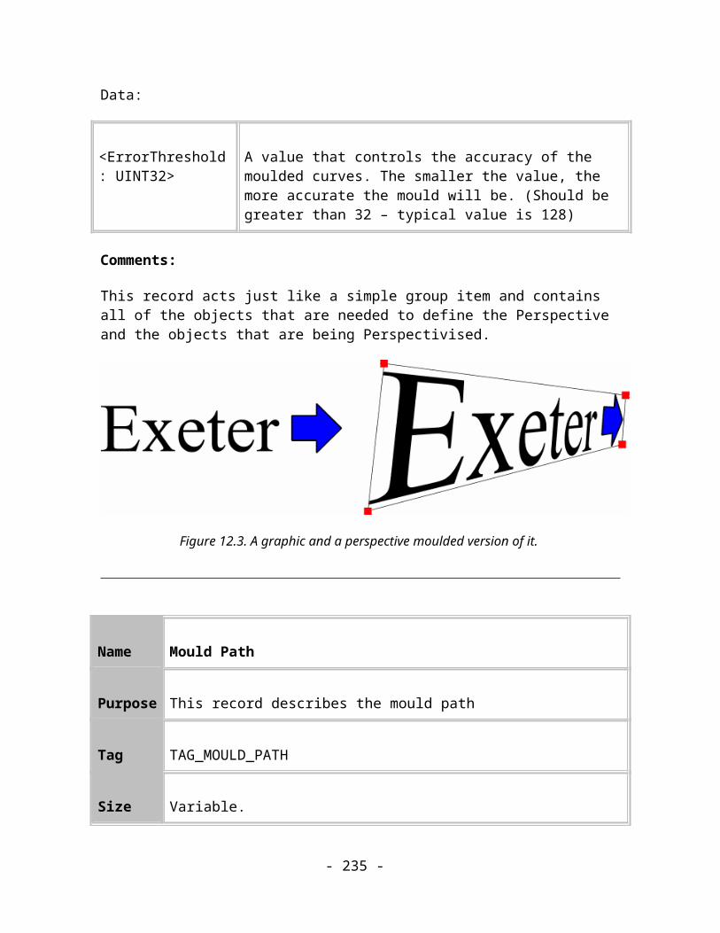
Comments:
This record specifies the kerning offset between two adjacent characters. For the purposes of editing, this can be treated as a hard space.
An “em” is a standard unit used when dealing with text. It represents the width of a lower case m character. Defining this record in terms of ems means that it doesn’t need to be modified if the text story is scaled as the attributes applied to the kern will be scaled resulting in the correct appearance.
This record must be a child of TAG_TEXT_LINE.
Name Horizontal tab
Purpose Represents a horizontal tab object
Tag TAG_TEXT_TAB
Size 0
Usage Image. Compulsory.
Comments:
This record represents a horizontal tab. This causes the current text position to move to the next tab stop defined by the current ruler attribute. If the text position is beyond the last tab stop, implicit left align tab stops are assumed to be present at full multiples of 1cm (measured from the tab stop ruler origin). Please note that in contrast to various other applications the left and first line indent values (see TAG_TEXT_LEFT_INDENT and TAG_TEXT_FIRST_INDENT) do not define implicit tab stops.
This record must be a child of TAG_TEXT_LINE.
- 235 -

Name Soft or hard hyphen
Purpose Represents a special hyphen object (soft or hard).
Tag TAG_TEXT_SPECIAL_HYPHEN
Size 1
Usage Image. Compulsory.
Data:
<Flags : BYTE> Details about whether the hyphen is soft or hard and whether a compatibility hyphen character has been saved.
Flags ::= <IsSoft : BIT(0)><KillPrev : BIT(1)>
Comments:
This record is only needed by editors and can be ignored by renderers.
This record represents a soft (IsSoft=1) or hard (IsSoft=0) hyphen. Soft hyphens mark a possible hyphenation point and do not show except when they are used for word wrapping, i.e., when the word is wrapped at the soft hyphen and the following character is not a whitespace character. Hard hyphens are always displayed but do not mark a possible hyphenation point for word wrapping.
If KillPrev=1 then this hyphen is visible (always the case for a hard hyphen, only sometimes the case for a soft hyphen) and an ordinary hyphen text character record has been saved just before this record for backwards compatibility - please note that in this case the applied attributes were saved as children of the ordinary hyphen character and are not repeated as children of the special hyphen record.
This record must be a child of TAG_TEXT_LINE.
- 236 -

Name Soft return
Purpose Represents a soft return.
Tag TAG_TEXT_SOFT_RETURN
Size 0
Usage Image. Compulsory.
Comments:
This record is only needed by editors and can be ignored by renderers.
This record represents a soft return. A soft return causes a line break without starting a new paragraph.
This record must be a child of TAG_TEXT_LINE.
Name Text Cursor or “caret”
Purpose Insertion point marker
Tag TAG_TEXT_CARET
Size 0
Usage Framework. Optional.
Comments:
- 237 -

This record is used to mark the position of the caret in the text story. It is only needed by editors and can be ignored by renderers.
Name Text line
Purpose Groups together several Text Objects
Tag TAG_TEXT_LINE
Size 0
Usage Image. Compulsory.
Comments:
This record describes one line of text within a text story. It is the parent of records such as TAG_TEXT_STRING and TAG_TEXT_CHAR which are used to compose the line of text.
This record must be a child of TAG_TEXT_STORY_XXX.
Name Text line information
Purpose Describe the size and relative position of a single line of text
Tag TAG_TEXT_LINE_INFO
Size 12
- 238 -

Usage Image. Compulsory.
Data:
<Width : MILLIPOINT> The width of the line of text.
<Height : MILLIPOINT> The height of the line of text.
<Offset : MILLIPOINT> The vertical distance between this line of text and the previous line (baseline to baseline).
Comments:
This record contains information about an individual line of text to help a renderer to display text without needing to understand the complex formatting algorithm that determines the positions of text lines relative to each other.
This information is also useful if font substitution has taken place. It can be used to ensure that text in the substituted font fills roughly the same area of the image by scaling it so that it fits into the Width and Height of the line.
(If a full text formatter is available, consider using the information in TAG_TEXT_STORY_WORD_WRAP_INFO instead.)
Name Text word wrapping information
Purpose Describe the parameters controlling a block of text
Tag TAG_TEXT_STORY_WORD_WRAP_INFO
Size 5
- 239 -
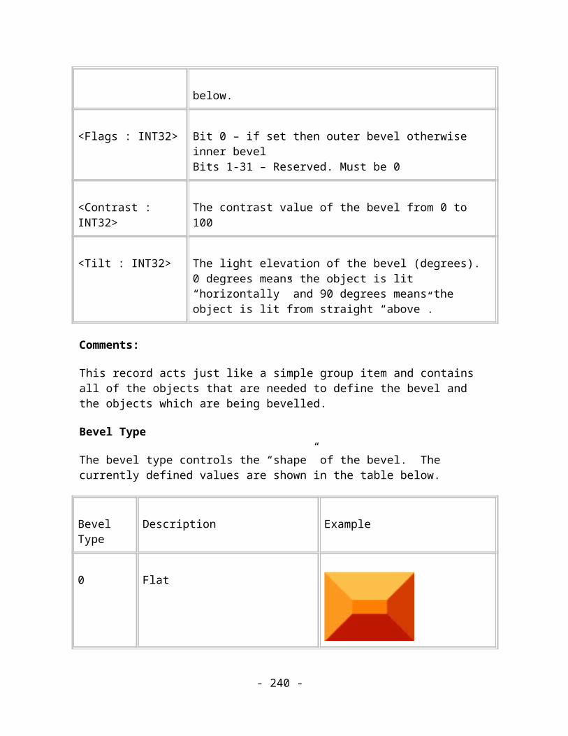
Usage Image. Optional.
Data:
<BlockWidth : MILLIPOINT>
The width of the block of text.
<Flags : BYTE> Non-zero enables word wrapping.Zero disables word wrapping.
Comments:
This record can be used to reformat the text inside a column of the width specified. To use this record properly a program will need a sophisticated text formatter. It is thus only suitable for use in editing applications. Simple Renderers should use the information supplied in TAG_TEXT_LINE_INFO instead.
Name Text indent information
Purpose Describe the margins within a block of text
Tag TAG_TEXT_STORY_INDENT_INFO
Size 8
Usage Image. Optional.
Data:
<LeftIndent : MILLIPOINT> The left indent inside the column defined by the text
- 240 -

anchor point and the word wrapping information record.
<RightIndent : MILLIPOINT> The right indent inside the column defined by the text anchor point and the word wrapping information record.
Comments:
This record can be used to reformat the text inside a column of the width specified. To use this record properly a program will need a sophisticated text formatter. Simple Renderers should use just the LeftIndent value to calculate the position of the baseline and then use the information supplied in TAG_TEXT_LINE_INFO instead attempting to format text within these margins.
Name Text area height information
Purpose Describe the parameters controlling a block of text
Tag TAG_TEXT_STORY_HEIGHT_INFO
Size 4
Usage Image. Optional.
Data:
<Height : LONG> The height of the text story. If this is non-zero then this turns the story into a text area.
Comments:
This record sets the height of a text area object. To use this record properly a program will need a sophisticated text formatter. It is thus only suitable for use in editing applications.
- 241 -

Simple Renderers should use the information supplied in TAG_TEXT_LINE_INFO instead.
Name Text story link information
Purpose Describe the linking of text stories into flowing text stories
Tag TAG_TEXT_STORY_LINK_INFO
Size 9
Usage Image. Optional.
Data:
<Flags : BYTE> Link flags, see below.
<NextInFlowID : UINT32> The ID of the text area that this text area flows into (0xFFFFFFFF if there is no next area).
<ThisID : UINT32> The ID of this area of text.
Flags ::= <LineAdded : BIT(0)><EOLAdded : BIT(1)>
The LineAdded flag is set to indicate that a virtual line has been added to this area (for backwards compatability) because it was empty. This line should be deleted by flow-aware importers.The EOLAdded flag is set to indicate that a virtual EOL has been added to the last line of this area (for backwards compatability). The EOL should be deleted for flow-aware importers.
Comments:
- 242 -

This record represents the linkage of text areas into flowing text stories and also includes information to undo normalisations done for backwards compatability. To use this record properly a program will need a sophisticated text formatter. It is thus only suitable for use in editing applications. Simple Renderers should use the information supplied in TAG_TEXT_LINE_INFO instead.
Name Text area translation information
Purpose Describe the real position of the story matrix for text areas.
Tag TAG_TEXT_STORY_TRANSLATION_INFO
Size 8
Usage Image. Optional.
Data:
<Position : COORD> This is the real translation offset part of the story matrix for text areas.
Comments:
This record sets the real position of the text area. The translation stored in the matrix in the story record is an adjusted value so that non-area-aware importers that treat the area as a text column render the text at the correct position. To use this record properly a program will need a sophisticated text formatter. It is thus only suitable for use in editing applications. Simple Renderers should use the information supplied in TAG_TEXT_LINE_INFO instead.
- 243 -

Text Attributes
Name Line spacing attribute for lines of text
Purpose Sets the text line linespacing attribute.
Tag TAG_TEXT_LINESPACE_RATIO
Size 4
Usage Image. Optional.
Data:
<LineSpacingRatio : FIXED16>
Line spacing as a ratio of the current font size
Comments:
The linespacing is the distance between the baselines of consecutive lines of text. This record sets the linespacing as a ratio of the largest font size in the line. A simple renderer does not need to process this attribute if it is using the information given by TAG_TEXT_LINE_INFO.
Name Line spacing attribute for lines of text
Purpose Sets the text line spacing attribute as an absolute distance.
Tag TAG_TEXT_LINESPACE_ABSOLUTE
- 244 -
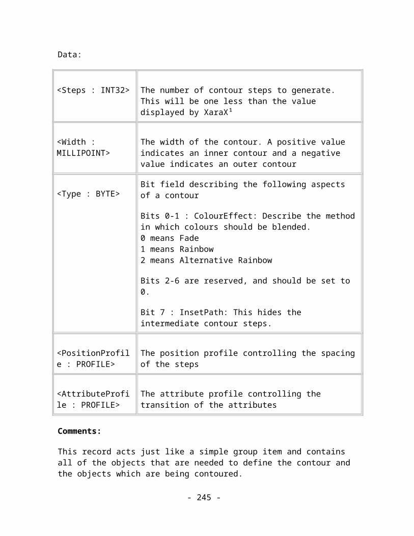
Size 4
Usage Image. Optional.
Data:
<LineSpacingAbsolute : MILLIPOINT>
Line spacing as an absolute measurement in millipoints
Comments:
Sets the linespacing between this line and the next to be absolute value, regardless of the size of any fonts on the line. A simple renderer does not need to process this attribute if it is using the information given by TAG_TEXT_LINE_INFO.
Name Line spacing attribute for lines of text
Purpose Sets the text line spacing attribute as an absolute leading value.
Tag TAG_TEXT_LINESPACE_LEADING
Size 4
Usage Image. Optional.
Data:
<LineSpacingLeading : MILLIPOINT>
Line spacing as an absolute leading measurement in millipoints
- 245 -

Comments:
This record is never currently saved and is defined so that plugin import filters for formats that describe line spacing as leading values (leading is the absolute distance of this line’s baseline from the previous line’s baseline). If this attribute is used in a story then each line should have an applied leading attribute as mixing leading and the other linespacing attributes is not logical and will almost certainly not give the desired result.
Name Justification attributes
Purpose Sets the text line justification attribute to no justification
Tag TAG_TEXT_JUSTIFICATION_LEFT,TAG_TEXT_JUSTIFICATION_CENTRE,TAG_TEXT_JUSTIFICATION_RIGHT,TAG_TEXT_JUSTIFICATION_FULL
Size 0
Usage Image. Compulsory.
Comments:
Sets the method of justification for text to one of the four familiar methods found commonly in Word Processors. When applied to a single text line, the text is justified relative to the anchor point. When applied to blocks of text or text on a path, the text is justified within the margins set by those objects.
Name Font size attribute for characters
Purpose Sets the text character font size attribute.
- 246 -

Tag TAG_TEXT_FONT_SIZE
Size 4
Usage Image. Compulsory.
Data:
<FontSize : MILLIPOINT> Font size measured in millipoints
Comments:
Sets the text font size.
(See the related section Fonts and Typeface attributes below.)
Name Text Effect “On” attributes
Purpose Sets certain text display flags
Tag TAG_TEXT_BOLD_ON,TAG_TEXT_ITALIC_ON,TAG_TEXT_UNDERLINE_ON,TAG_TEXT_SUPERSCRIPT_ON, TAG_TEXT_SUBSCRIPT_ON
Size 0
Usage Image. Compulsory
Comments:
- 247 -
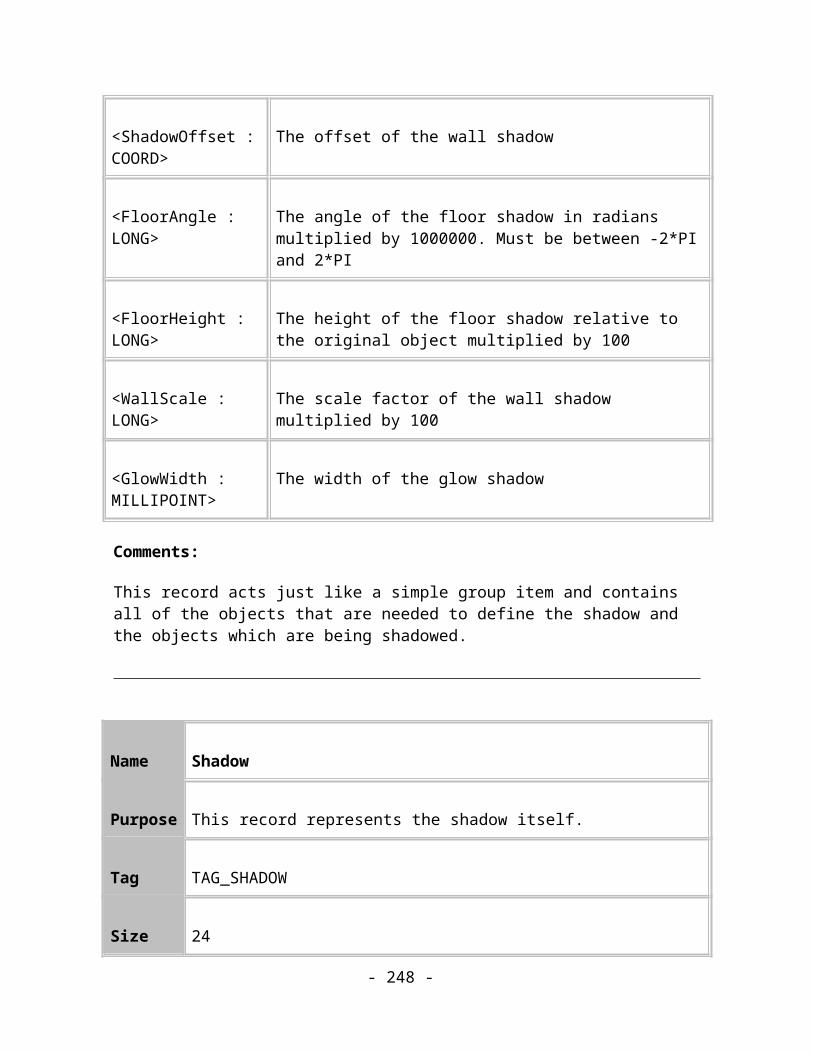
These records turn on one of the standard font appearance attributes, Bold, Italic and Underline, as commonly found in Word Processors. The TAG_SUPERSCRIPT_ON and TAG_SUBSCRIPT_ON attributes use default offsets and sizes. (See Appendix B for the defaults).
Name Text Effect “Off” attributes
Purpose Clears certain text display flags
Tag TAG_TEXT_BOLD_OFF,TAG_TEXT_ITALIC_OFF,TAG_TEXT_UNDERLINE_OFF,TAG_TEXT_SCRIPT_OFF
Size 0
Usage Image. Compulsory
Comments:
These records turn off one of the standard font appearance attributes, Bold, Italic, Underline and Script. They remove the effects of the “On” attributes listed above.
Name Defines the appearance of super- or subscript text
Purpose Describes the size and offset of script text.
Tag TAG_TEXT_SCRIPT_ON
- 248 -

Size 8
Usage Image. Compulsory.
Data:
<ScriptFontSize : FIXED16>
Size of the script text, as a fraction of the current font size attribute
<ScriptOffset : FIXED16>
Position of the script text, as a fraction of the current font size attribute.
Comments:
Defines the font size and offset ratios needed for rendering super- and subscript type.
Default values for this attribute (like all others) are listed in Appendix B. The Offset field gives the position of the baseline of the script text relative to the baseline of the text before it.
Name Tracking attribute for text characters
Purpose Sets the text character tracking attribute.
Tag TAG_TEXT_TRACKING
Size 4
Usage Image. Compulsory.
Data:
- 249 -
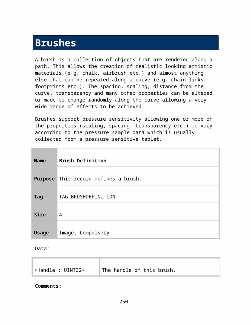
<Tracking : LONG> New tracking attribute, measured in 1000s of ems
Comment:
The text tracking attribute alters the density of characters by pulling them closer together or pushing them further apart. The signed Tracking value specifies a distance by which each character in the scope of this attribute should be pushed further away from the previous character. A negative value will pull the characters closer together.
Name Aspect ratio attribute for text characters
Purpose Sets the text character aspect ratio attribute
Tag TAG_TEXT_ASPECT_RATIO
Size 4
Usage Image. Compulsory.
Data:
<AspectRatio : FIXED16>
New aspect ratio attribute value
Comments:
Sets the text character aspect ratio attribute, a ratio of X scaling to Y scaling. A value of 1 is equivalent to a ratio of 100% or 1:1. A ratio of 1.2, or 120%, gives expanded, “fat”, type, 0.8 or 80% gives condensed, “thin”, type.
- 250 -
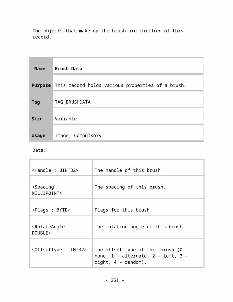
Name Baseline shift attribute for text characters
Purpose Sets the text character baseline shift attribute.
Tag TAG_TEXT_BASELINE
Size 4
Usage Image. Compulsory.
Data:
<BaseLineShift : MILLIPOINT>
New baseline shift, in millipoints
Comments:
This signed value is used to move the baseline of the text within its scope relative to the previous baseline. Positive values move the new baseline up and negative values move it down.
Name Ruler attribute for lines of text
Purpose Describes tab stops that apply to a line of text
Tag TAG_TEXT_RULER
Size Variable
- 251 -

Usage Image. Compulsory.
Data:
<Count : UINT16> The number of tab stop entries in the record. The following entries are repeated for each tab stop.
<TypeAndFlags : BYTE>
This represents the type of the tab stop and whether a tab filler character is specified.
<Position : INT32> The position of the tab stop.
<DecimalChar : UINT16>
Optional. This is the character that is aligned to the decimal tab. This item is only present if the TypeAndFlags item specifies a decimal tab stop.
<FillerChar : UINT16>
Optional. This is the filler character. This item is only present if a filler char is specified by the TypeAndFlags item. (TabFillerPresent flag set).
TypeAndFlags ::= <TabStopType : BITS(0,1)><TabFillerPresent : BIT(2)>
Interpretation of the TabStopType field:
Name Value Meaning
LeftTab 0x0 Left align tab stop.
RightTab 0x1 Right align tab stop.
CentreTab 0x2 Centre align tab stop.
- 252 -

DecimalTab 0x3 Decimal tab stop.
Comments:
This is a line level attribute so must only be applied to whole lines. It defines the position and type of the tab stops for the line.
Name Indent attributes for text lines
Purpose Sets the left, right or first line indents of text lines
Tag TAG_TEXT_LEFT_INDENTTAG_TEXT_FIRST_INDENTTAG_TEXT_RIGHT_INDENT
Size 4
Usage Image. Compulsory.
Data:
<Value : INT32> The indent value applied. The left and first line indents are measured from the physical left boundary of the text. The right indent is measured from the physical right boundary of the text (only meaningful for text objects with word wrapping enabled because only these have fixed widths).
Comments:
This is a line level attribute so must only be applied to whole lines.
Do not confuse the indents of text lines with the physical indents defined by TAG_TEXT_STORY_INDENT_INFO. The latter define the physical boundaries for the
- 253 -

complete text in a text object, the former affect formatting within the physical boundaries and can be different for each paragraph of text.
Name Space before/after attributes for text lines
Purpose Sets the space before or after a paragraph.
Tag TAG_TEXT_SPACE_BEFORETAG_TEXT_SPACE_AFTER
Size 4
Usage Image. Compulsory.
Data:
<Value : MILLIPOINT>
The spacing value applied.
Comments:
This is a line level attribute so must only be applied to whole lines.
Please note that paragraph spacing in Xtreme is not accumulative, i.e., if a paragraph with a space before value follows a paragraph with a space after value, then the resulting spacing is not the sum of the two values but the maximum.
- 254 -

Fonts and Typeface attributes
Introduction
Xar format can refer to Truetype and Adobe Type1 fonts on the Windows platform. Enough information is given in those font specification records that it should be possible to find the equivalent font on other platforms.
Like colours and bitmaps, font specifications can be quite large and since they may be referred to frequently the Reusable Records system is used to avoid repeating the specification every time it is needed.
This revision of the Xar format does not attempt to embed fonts or partial fonts within documents.
Some terminology
A glyph is a single renderable object. It may represent several (Unicode) characters, or a single (Unicode) character may require many glyphs to be rendered.
A font is a collection of glyphs that share a common design. The three major elements of this design are the typeface, style and size.
The term typeface refers to the specific characteristics of glyphs, such as the width and design of the thin and thick, horizontal and vertical strokes and the presence or absence of serifs which make up the glyphs.
The term style of a font refers to the weight and slant of a font. Font weights can range from thin to black, i.e. thin ... normal ... bold ... heavy. The slant of a font can be any of three values; roman, oblique or italic. The glyphs in a roman font are upright, those in a oblique font are artificially slanted and those in an italic font are designed slanted. The slanting in oblique fonts is achieved by performing a shear transformation on the glyphs from the roman font, hence italic fonts may look better than oblique fonts.
If we concatenate the font name and style we get the full font name. For instance, “Times Roman” or “Arial Narrow Bold Italic”.
Information required by a text story
Putting together the information in the above sections we can say what information we need to uniquely specify a font and to help us choose a substitute font should the original font not be installed.
- 255 -
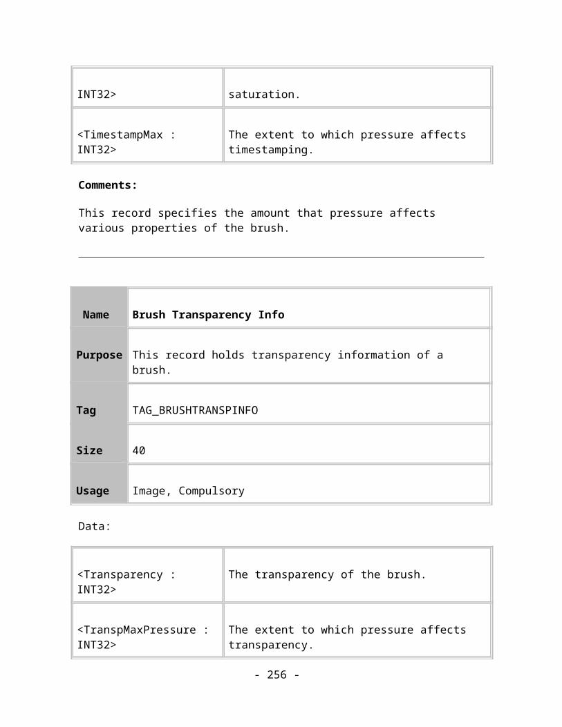
The style of a font should not be confused with the bold or italic attributes we can apply to text. When a bold or italic attribute is applied to a selection of text we can either find an appropriate font or generate bold or oblique glyphs to use to render the text. However the text still retains its full font name attribute.
Xar format assumes that the font technologies it uses are scaleable and that it’s able to store the size of the text separately from the description of the font; it doesn’t affect the font information.
Name Font specification
Purpose Specifies the attributes of a TrueType or ATM font.
Tag TAG_FONT_DEF_TRUETYPE,TAG_FONT_DEF_ATM
Size Variable
Usage Image. Compulsory.
Data:
<FullFontName : STRING>
Full font name
<TypeFaceName : STRING>
Typeface name
<PANOSE : 10 * BYTE> PANOSE number
Comments:
TAG_FONT_DEF_TRUETYPE specifies a font in the TrueType system.
TAG_FONT_DEF_ATM specifies a font in the Adobe Type Manager system.
- 256 -

These records contain all the information to describe fonts uniquely. They allow for intelligent font substitution in case the required font is not present. By itself these records do nothing, however TAG_TEXT_FONT_TYPEFACE records later in the file will reference them when a change of font attribute is required.
It may seem excessive storing both the full font name and the typeface name, especially when the typeface name is usually a prefix of the full font name. However this cannot be guaranteed.
Please note that the Panose information is not just for substituting fonts that are not installed. Its Weight and Letter form fields need to be interpreted in any case. If the Panose information refers to a bold (Weight > PAN_WEIGHT_MEDIUM) or italic (LetterForm > PAN_LETT_NORMAL_SQUARE) font, then a bold or italic variant of the typeface needs to be selected, irrespective of the applied bold or italic text effect attributes.
Programs exporting .xar files are strongly encouraged to never save Panose information with Weight > PAN_WEIGHT_MEDIUM or LetterForm > PAN_LETT_NORMAL_SQUARE and to always supply bold and italic information using separate text effect records.
The PANOSE font classification system
The PANOSE system classifies fonts by 10 different attributes. These attributes are rated individually on a scale. The resulting values are concatenated together to produce a 10 digit hexadecimal number. Given a number for a font and a mathematical metric to measure distances in the PANOSE space, an application can determine the nearest neighbours.
Briefly, the attributes represented in the PANOSE number are:
Family type Serif Style
Weight
Proportion
Contrast
Stroke Variation
Arm Style
Letter Form
Midline
- 257 -
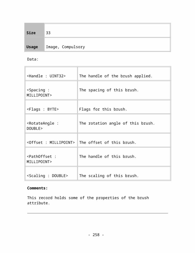
Height
Font Matching
A suggested font-matching algorithm is this:
1. Does a font exist with the same full font name and technology? If so then use it. (Font names are unique within their technology)
2. Does a font exist with the same full font name but different technology? If so then use it.
3. Do there exist fonts with the same typeface names and technology, if so then choose the closest font from this set using PANOSE numbers.
4. Do there exist fonts with the same typeface names but different technology, if so then choose the closest font from this set using PANOSE numbers.
5. If all the other methods fail, choose the closest font from all installed fonts using PANOSE numbers.
If a Reader is unable to find a close match to the specified font and is forced to substitute it with another then it should warn the user that it has done so and that the image may not look as the designer originally intended.
Name Font attribute
Purpose Sets the text font attribute.
Tag TAG_TEXT_FONT_TYPEFACE
Size Variable
Usage Image. Compulsory.
Data:
- 258 -
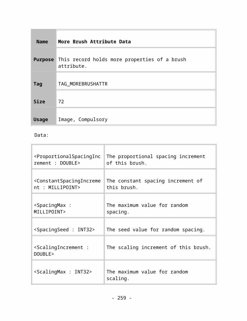
<RecordID : INT32> Sequence number of the TAG_TEXT_FONT_DEF_XXX record earlier in the file.
Comments:
Sets the text font attribute to a previously declared font.
Name Extra font information
Purpose Specifies the attributes of a TrueType or ATM font variant.
Tag TAG_TEXT_EXTRA_TT_FONT_DEF,TAG_TEXT_EXTRA_ATM_FONT_DEF
Size Variable
Usage Image. Optional.
Data:
<Flags: BYTE> Font definition flags (see below).
<FullFontName : STRING>
Full font name (full name of this particular variant)
<FullTypefaceName: STRING>
Full typeface name (full name of the base variant of this typeface)
<TypefaceName : STRING>
Typeface name
- 259 -
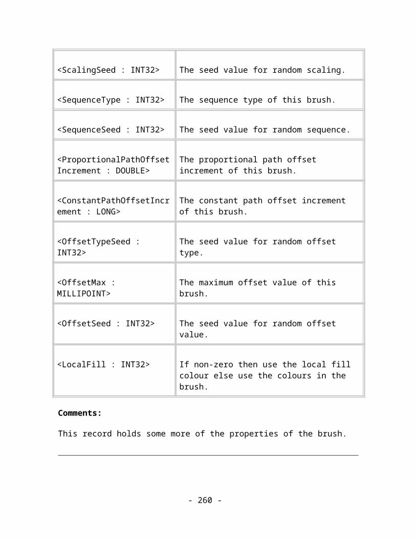
<Weight: INT16> The numeric weight to be used when selecting this variant.
<OriginalFontName: STRING>
The name of the font that has been replaced. This field is only present if the Replaced flag is set in the Flags field.
Flags ::= <Bold : BIT(0)><Italic: BIT(1)><Replaced: BIT(2)><ReplacedBold: BIT(3)><ReplacedItalic: BIT(4)>
Comments:
TAG_TEXT_EXTRA_TT_FONT_DEF specifies a font in the TrueType system.
TAG_TEXT_EXTRA_ATM_FONT_DEF specifies a font in the Adobe Type Manager system.
These records contain all the information to identify a specific font variant used to display a piece of text. In contrast to the standard font specification records, this record takes the applied bold and italic text effects into account. The font variant used to display is defined by the combination TypefaceName/Weight/Flags.Italic and is installed. By itself these records do nothing, however TAG_TEXT_EXTRA_FONT_INFO records later in the file will reference them when a change of font attribute is required.
If the font is replaced (Replaced flag set), then OriginalFontName, ReplacedBold and ReplacedItalic define the properties of the font that is replaced and all the other fields (including the TT/ATM distinction conveyed by the tag) refer to the font actually used for display.
These records are only written when exporting to a plugin filter that asks for extra font information.
Name Extra font attribute
Purpose Indicates a change of text font attribute.
- 260 -

Tag TAG_TEXT_EXTRA_FONT_INFO
Size Variable
Usage Image. Optional.
Data:
<RecordID : INT32> Sequence number of the TAG_TEXT_EXTRA_XXX_FONT_DEF record earlier in the file.
Comments:
Indicates that the effective font has changed. This record occurs after each sequence of text attribute changes (typeface, bold, italic) and refers to a definition record that specifies the exact font variant used for rendering.
This record is only written when exporting to a plugin filter that asks for extra font information.
Fitting Text to Paths
Text stories can be fitted to paths so that the characters flow along the path by treating the path as the baseline of the text. Individual characters are not warped to fit the path, they are just rotated and translated so that their baseline is tangential to the path at the appropriate position.
There can only be one path per text story.
Just to add a bit of spice to proceedings note that it is possible for the characters to be transformed individually as well as being fitted to the path. The SIMPLE records don’t transform the characters individually, the COMPLEX ones do.
- 261 -
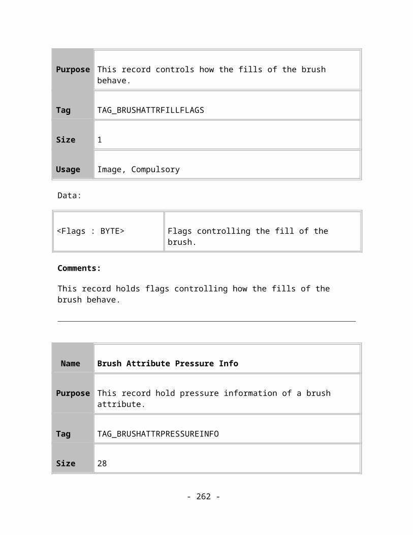
Figure 13.2. The two major types of text fitted to paths.
Each of the following TAG_TEXT_STORY_PATH_* records differ only in the orientation of the text when fitted to the path.
Name Text story fitted to a path
Purpose Path object for text stories
Tag TAG_TEXT_STORY_SIMPLE_START_LEFT,TAG_TEXT_STORY_SIMPLE_START_RIGHT,TAG_TEXT_STORY_SIMPLE_END_LEFT,TAG_TEXT_STORY_SIMPLE_END_RIGHT
Size 12 (8)
Usage Image. Compulsory.
Data:
<Anchor : COORD> Co-ordinate of anchor point of text.
< AutoKern : LONG >
Kerning flag. 0 – no kerning, 1 – automatic kerning.Note: this field may not be present in older Xar documents
Comments:
- 262 -

Each of these records describes a text story that is fitted to a path. The path used for fitting is a child of this record and it is rendered in the normal way – it doesn’t need to be treated differently to any other paths in the document.
This record represents text that isn’t rotated or sheared in any way while it is fitted to the path.
The magnitude of any scale transformations that have been applied to the text are implicitly represented in the co-ordinates and dimension attributes (such as font size or line width) of the text story.
See the Reflective variants section for a description of the meanings of the four variations of this record.
Name Text story fitted to a path
Purpose Path object for text stories
Tag TAG_TEXT_STORY_COMPLEX_START_LEFT,TAG_TEXT_STORY_COMPLEX_START_RIGHT,TAG_TEXT_STORY_COMPLEX_END_LEFT,TAG_TEXT_STORY_COMPLEX_END_RIGHT
Size 36 (32)
Usage Image. Compulsory.
Data:
<Transformation : MATRIX>
The transformation matrix describes the translation to move from 0,0 to the anchor point and also any rotation and shear that should be applied to the text story.
<Rotation : ANGLE> The angle of rotation that should be applied to each character after
- 263 -
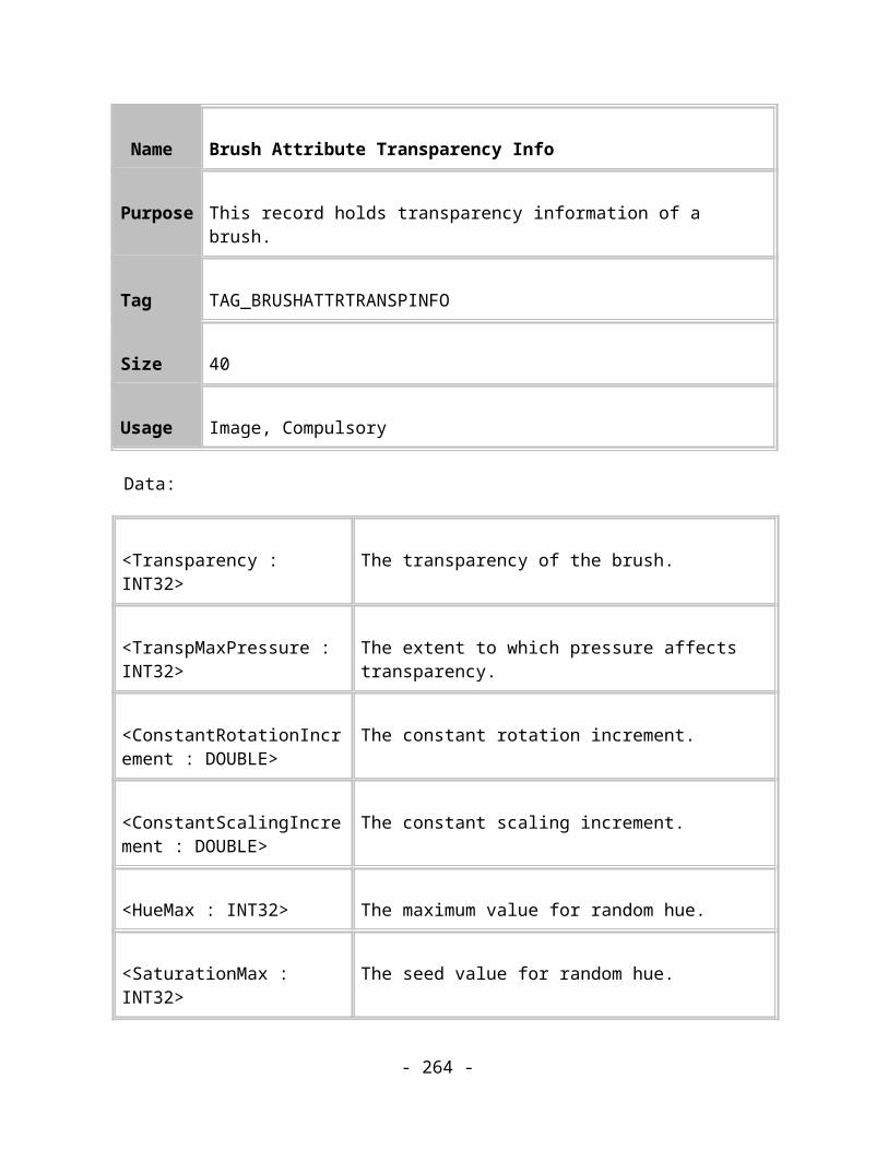
it has been positioned on the path.
<Shear : ANGLE> The angle of shear that should be applied to each character after it has been positioned on the path.
< AutoKern : LONG >
Kerning flag. 0 – no kerning, 1 – automatic kerning.Note: this field may not be present in older Xar documents
Comments:
These records represent text that is rotated or sheared as well as being fitted to a path!
The path used for fitting is a child of this record and it is rendered in the normal way – it doesn’t need to be treated differently to any other paths in the document.
The matrix specifies a global transform that is applied to the whole text story.
The angle and shear fields specify how to transform each character as it is fitted to the path. Editors can use this information to preserve the angle and shear of the text story that results when they remove the text from the path.
The magnitude of any scale transformations that have been applied to the text are implicitly represented in the co-ordinates and dimension attributes (such as font size or line width) of the text story.
See the Reflective variants section for a description of the meanings of the four variations of this record.
Reflective variants
The four variants of this record are used to encode any reflection transformations that have been applied to the text. Unlike scale transformations, reflective transformations can’t simply be stored implicitly in the co-ordinates and dimensions of the text story. The reason for this is that text is unlike most other graphical objects in that it has “direction”. The characters have to appear in a particular order to make sense and the cursor has to move through the characters appropriately. The record variants allow the direction of the text to be represented correctly.
The following list attempts to describe the differences between the variants, giving the reflective transformations for each one:
- 264 -

TAG_TEXT_STORY_SIMPLE_START_LEFT: The text is fitted to the left of the path, flowing forward along the path from the start. (X=0, Y=0)
TAG_TEXT_STORY_SIMPLE_START_RIGHT: The text is fitted to the right of the path, flowing forwards along the path from the start. (X=-1, Y=0)
TAG_TEXT_STORY_SIMPLE_END_LEFT: The text is fitted to the left of the path, flowing backwards along the path from the end. (X=0, Y=-1)
TAG_TEXT_STORY_SIMPLE_END_RIGHT: The text is fitted to the right of the path, flowing backwards along the path from the end. (X=-1, Y=-1)
The shear and the absolute values of the scalings are used when fitting the text to the path, the sign of the scalings and the rotation get used to determine where on the path the text is to be fitted. There are four different path attributes for text stories, one for each position on path that the text may be placed. The algorithm for fitting text is:
if Xsign = -1 then the text begins from the other end of the path (swap start for end etc.)
if Ysign = -1 then the text lies on the other side of the path (swap top for bottom).
Figure 13.3. The effects of transform attributes on text fitted to a path.
- 265 -

BitmapsThere are two main types of bitmap records, one type for the preview bitmaps, or “thumbnails”, optionally stored at the start of the file and the other type for all Image bitmap records. The Preview bitmaps are Framework records that don’t appear in the image itself. The Image bitmaps may be rendered directly in the image or may be used as fills in other shapes.
Embedded bitmaps
When the user drops (or imports) a JPG or PNG bitmap onto their document this original file is embedded in the Xar file. It is not de-compressed and re-compressed so avoiding decode / encode losses that happen for JPEG files. This not only saves a huge amount of space in the resulting file, it also enables the original untouched, full resolution image is available for export or printing purposes.
In Xara X¹ and later versions it’s possible to edit embedded bitmaps using the Xara Picture Editor. The XPE has the ability to record bitmap edits in a XML edit list, so rather than having to create and store the edited bitmap, Xara stores just the XPE Edit list and re-constructs the edited bitmap upon load. This also has huge space saving implications, (you can use edited copies of your photos with a near zero file space overhead) as well as the advantage of being able to further edit or undo previous bitmaps edits.
In the case of using a ‘destructive plug-in’ such as non-scriptable Photoshop effects, these produce a new full-size edited bitmap, and are stored as lossless PNG in the Xar file.
Preview Bitmap
The Preview bitmap is optional. When present, it appears at the start of the file so that it can be recovered quickly for displaying in situations where a quick view of the image is required – often in replacement for file icons. The preview bitmap record must not be in a region of the file that has been compressed by Zlib. Further, unless there is a very good reason otherwise, it should also be the first record found after the File Header in the header records section. These stipulations make the Preview Bitmap easily available to simple programs since they don’t have to understand the full details of the Xar format.
This record holds a small bitmap, with a pre-rendered version of the document in it. The bitmap can be any size, any resolution and any colour depth. The recommended settings are, 128*128 pixels (resolution depends on the size of the image being previewed) and 256 colours.
The Preview Bitmap is generally not found in files intended for publishing on the Web because the byte overhead of this record is too great.
- 266 -

Preview Bitmaps are usually held either in GIF or PNG format because those formats best express the recommended 256-colour preview image.
Name Preview Bitmap GIF
Purpose This record defines a preview bitmap in GIF format
Tag TAG_PREVIEWBITMAP_GIF
Size Variable
Usage Framework. Optional
Data:
<Bitmap data> Data to store the bitmap in the specified format.
<Bitmap data> ::= Data to store the bitmap in the specified format.
Comments:
This record holds the preview bitmap in the form of a GIF. The bitmap data will therefore consist of a straight definition of the bitmap using the GIF format standard.
Name Preview Bitmap JPEG
Purpose This record defines a preview bitmap in JPEG format
Tag TAG_PREVIEWBITMAP_JPEG
- 267 -

Size Variable
Usage Framework. Optional.
Data:
<Bitmap data> Data to store the bitmap in the specified format.
<Bitmap data> ::= Data to store the bitmap in the specified format.
Comments:
This record holds the preview bitmap in the form of a JPEG.
Name Preview Bitmap PNG
Purpose This record defines a preview bitmap to the system.
Tag TAG_PREVIEWBITMAP_PNG
Size Variable
Usage Framework. Optional
Data:
<Bitmap data> Data to store the bitmap in the specified format.
<Bitmap data> ::= Data to store the bitmap in the specified format.
- 268 -

Comments:
This record holds the preview bitmap in the form of a PNG.
Bitmap references
Any references made to bitmaps from other records actually just contain a Sequence Number, which refers to a bitmap definition record. The bitmap definition record must be appear before it is actually referenced by any Sequence Number and it usually appears just prior to the first record that refers to it. Thus, when the Xar file is being transmitted down a slow communications channel, such as a modem link to the Internet, the bitmap information is transmitted just before it is used. This system ensures that as much of the image preceding the bitmap is downloaded onto the user’s machine and shown to him before a potentially slow bitmap download starts.
If the format of the bitmap is unknown to the Reader then it can substitute a default bitmap of its own. This is defined at the end of this chapter.
Bitmap Definition Records
Bitmap Definition Records use industry standard bitmap encodings, JPEG and PNG, which are both compressed formats. The two formats have different strengths: JPEG is ideal for high BPP, photographic images and its compression is “lossy”. PNG is ideal for low BPP, computer-generated images or where non-lossy images are required. The PNG format supports alpha-channel transparency (mix type only) and so is used a lot internally where alpha-channel bitmaps are required For example where an export filter specifis that it requires bitmaps to represent certainl object types, these will be converted to alpha-channel PNGs and stored in the xar file this way.
Since both bitmap formats are compressed, Xar format often turns off its own Zlib compression around these definition records. It is unlikely that the Zlib compression stage would have any useful effect on the sizes of these records and, more significantly, attempting to compress them would probably upset the Zlib compression dictionaries, possibly making the compression of following records less efficient.
Name Define Bitmap JPEG
Purpose This record defines a bitmap to the system in the form of a JPEG.
- 269 -

Tag TAG_DEFINEBITMAP_JPEG
Size Variable
Usage Image. Compulsory.
Data:
<Bitmap name : STRING>
The name of the bitmap. Can be an empty string, in which case the bitmap is unnamed and should be given a default name. It is recommended that this field is empty for Web-only publishable files. (NULL terminated).
<Bitmap data> Data to store the bitmap in the specified format.
<Bitmap data> ::= Data to store the bitmap in the specified format.
Comments:
This record defines a bitmap in JPEG format for later use in the image.
Name Define Bitmap 8bpp JPEG
Purpose This record defines a bitmap to the system in the form of a JPEG.
Tag TAG_DEFINEBITMAP_JPEG8BPP
Size Variable
Usage Image. Compulsory.
- 270 -

Data:
<Bitmap name : STRING>
The name of the bitmap. Can be an empty string, in which case the bitmap is unnamed and should be given a default name. It is recommended that this field is empty for Web-only publishable files. (NULL terminated).
<Palette data> Data to store the palette for the bitmap
<Bitmap data> Data to store the bitmap in the specified format.
<Bitmap data> ::= Data to store the bitmap in the specified format.
Comments:
This record holds the bitmap in the form of a JPEG. It has the addition of a palette definition. The bitmap data is really of an 8bpp coloured bitmap which has been converted to 24bpp and then JPEG compressed. When loaded, it can be converted back to 8bpp using the specified palette. The palette is saved in RGB Triple format. It consists of a byte indicating the number of entries in the palette followed by that number of entries saved out as a byte each for the red, green and blue palette items.
Name Define Bitmap PNG
Purpose This record defines a bitmap to the system in the form of a PNG.
Tag TAG_DEFINEBITMAP_PNGTAG_DEFINEBITMAP_PNG_REAL
Size Variable
Usage Image. Compulsory.
- 271 -

Data:
<Bitmap name : STRING>
The name of the bitmap. Can be an empty string, in which case the bitmap is unnamed and should be given a default name. It is recommended that this field is empty for Web-only publishable files. (NULL terminated).
<Bitmap data> Data to store the bitmap in the specified format.
<Bitmap data> ::= Data to store the bitmap in the specified format.
Comments:
This record defines a bitmap in PNG format for later use in the image. When this record contains a 32 bpp RGBA bitmap, the alpha channel will be inverted from the normal sense stored in PNG files (e.g. if the image is treated as a normal PNG then the transparent areas of the image will be opaque and the opaque areas will be transparent).
The TAG_DEFINEBITMAP_PNG_REAL record is a variant that does not store 32bpp RGBA bitmaps with the alpha channel inverted. This is currently only used when exporting via a plugin filter (and only if the filter asks for it) to remove the need for the filter to mess around with the bitmap.
Name Bitmap Properties
Purpose This record holds extra information about bitmap definition records.
Tag TAG_BITMAP_PROPERTIES
Size 12
Usage Image. Compulsory.
Data:
- 272 -

<Bitmap : BITMAPREF> A reference to the bitmap that this record refers to.
<Flags : BYTE> Flags. Bit 0 – use interpolation when rendering this bitmapBits 1-7 are reserved, must be set to 0
<Reserved : 7 BYTEs> Reserved. Must be set to 0
Name XPE Bitmap Definition
Purpose This record defines an XPE generated bitmap. The reference to the source bitmap and the list of edits to apply are contained in a XPE Bitmap Properties record.
Tag TAG_DEFINEBITMAP_XPE
Size 0
Usage Image. Compulsory.
Name XPE Bitmap Properties
Purpose This record holds extra information about XPE generated bitmap definition records.
Tag TAG_XPE_BITMAP_PROPERTIES
- 273 -
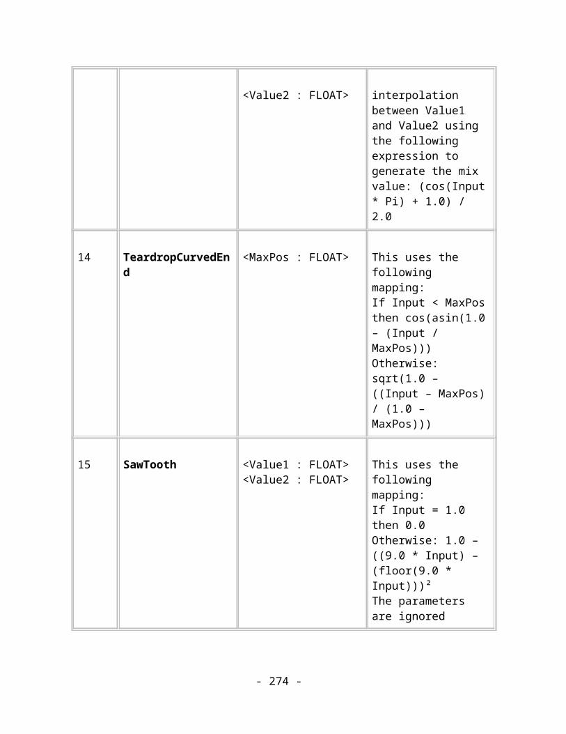
Size Variable
Usage Image. Compulsory.
Data:
<Bitmap : BITMAPREF> A reference to the bitmap that this record refers to.
<Flags : BYTE> Flags. Bit 0 – use interpolation when rendering this bitmapBits 1-7 are reserved, must be set to 0
<Reserved : 7 BYTEs> Reserved. Must be set to 0
<MasterBitmap : BITMAPREF>
A reference to the source bitmap of this XPE generated bitmap.
<BitmapName : STRING> The name of this bitmap.
<EditList : STRING> The XML XPE edit list required to generate this bitmap.
Comments:
This record defines a bitmap that is created from another bitmap definition by applying various “editing” operations on it using the Xara Photo Editor (XPE). These operations can include (but are not limited to) altering the brightness, contrast or saturation, cropping, rotating and rescaling. The format of the XML XPE edit list is available in the documentation for the Xara Photo Editor.
Unknown bitmaps
It’s possible that a Reader parsing a Xar file might not understand a bitmap definition, or that the record referred to by a Bitmap Reference isn’t a bitmap definition record. In these circumstances the Reader should use a default bitmap, that it has guaranteed access to, in the unknown bitmap’s place.
- 274 -

It is polite to warn the user that such a substitution has taken place because the image that will now be rendered won’t appear how the designer intended it to. This warning should be given in as unobtrusive a way as possible.
Contone Bitmap Objects
A Contone bitmap has a palette of colours that change smoothly from one colour to another – a continuous tone.
Usually, a bitmap record representing a bitmap object does not have any line or fill colour applied to it (i.e. it has Line Colour None and Fill Colour None applied). However, if the record has either a line or a fill colour (or both), then it is rendered as a contone bitmap. The bitmap must then be converted or treated as a grey scale bitmap, where the levels of grey are replaced by colours generated by interpolating between the fill and line colours. The fill colour replaces white, and the line colour replaces black, and all grey levels lie in between these two colours.
Document Bitmap Objects
Documents can contain bitmaps on the page through the following records:
Name Bitmap Object
Purpose This record describes a bitmap on the page of the current document.
Tag TAG_NODE_BITMAP
Size 36
Usage Image. Compulsory.
Data:
<BottomLeft : COORD>
The bottom left-hand co-ordinate of the parallelogram bounding the bitmap image.
- 275 -

<BottomRight : COORD>
The bottom right-hand co-ordinate of the parallelogram bounding the bitmap image.
<TopRight : COORD> The top right-hand co-ordinate of the parallelogram bounding the bitmap image.
<TopLeft : COORD> The top left-hand co-ordinate of the parallelogram bounding the bitmap image.
<Bitmap : BITMAPREF>
A reference to the bitmap to show in the bounding parallelogram.
Name Contone Bitmap Object
Purpose This record describes a contone bitmap on the page of the current document.
Tag TAG_NODE_CONTONEDBITMAP
Size 44
Usage Image. Compulsory.
Data:
<BottomLeft : COORD> The bottom left-hand co-ordinate of the parallelogram bounding the bitmap image.
<BottomRight : COORD> The bottom right-hand co-ordinate of the parallelogram bounding the bitmap image.
- 276 -

<TopRight : COORD> The top right-hand co-ordinate of the parallelogram bounding the bitmap image.
<TopLeft : COORD> The top left-hand co-ordinate of the parallelogram bounding the bitmap image.
<Bitmap : BITMAPREF> A reference to the bitmap to show in the bounding parallelogram.
<StartColour : COLOURREF>
A reference to the first colour in the continuous-tone bitmap palette.
<EndColour : COLOURREF>
A reference to the last colour in the continuous-tone bitmap palette.
- 277 -

Bitmap Effect Records
Name Live Effect
Purpose This record describes a Live Effect object.
Tag TAG_LIVE_EFFECT
Size Variable
Usage Image. Compulsory.
Data:
<Flags : BYTE> Currently unused. Should be set to 0.
<DPI : DOUBLE> Pixels per inch value for this effect. May be 0 in which case the resolution of the effect will be obtained from the objects around it and global settings.
<EffectID : String> The unique internal identifier of the effect. Guaranteed to remain constant across all installations on different platforms.
<DisplayName : String>
The name of the effect shown to the user. May be localised.
<EditsXML : String> The XML document containing the parameters for the effect. The format of this document is determined by the “Xara Picture Editor”.
- 278 -
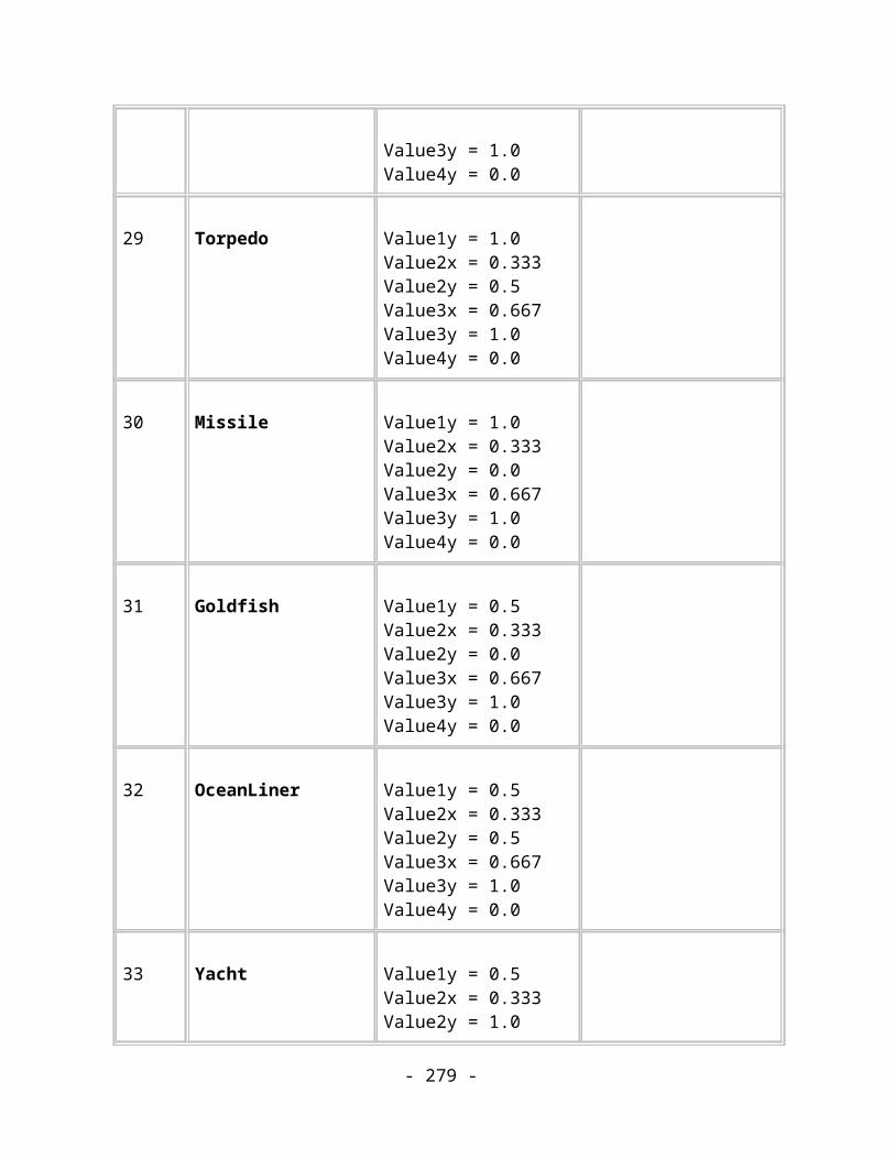
Comments:
A Live effect is linked to a bitmap effect whose parameters are stored in the XML document. Those parameters can be edited after the original bitmap has been created or applied to different source bitmaps. This allows the effect to be automatically re-applied to vector objects when they change. Hence the term, “live effect”.
A Live effect object can contain child objects in the same way as a group and the bitmap effect is applied to those objects. To render a live effect, you must make the child objects render into a bitmap, pass the bitmap to the effect processor specified by the EffectID then render the resulting bitmap into the document. Most common effects are produced by Photoshop plugins but a few are specially implemented by Xara X and a few by special plugins of the Xara Picture Editor.
The DPI should be used to control the resolution of the bitmap. If it’s zero, then the resolution should be taken from any parent effects, child effects or child bitmaps. The exact algorithm is beyond the scope of this document.
The content of the EffectID string is managed by Xara Picture Editor.
The content of the DisplayName string is managed by Xara Picture Editor.
The content of the EditsXML string is managed by Xara Picture Editor.
Further information about any of these things can be supplied on request.
Name Locked Effect
Purpose This record describes a Locked Effect object.
Tag TAG_LOCKED_EFFECT
Size Variable
Usage Image. Compulsory.
Data:
- 279 -
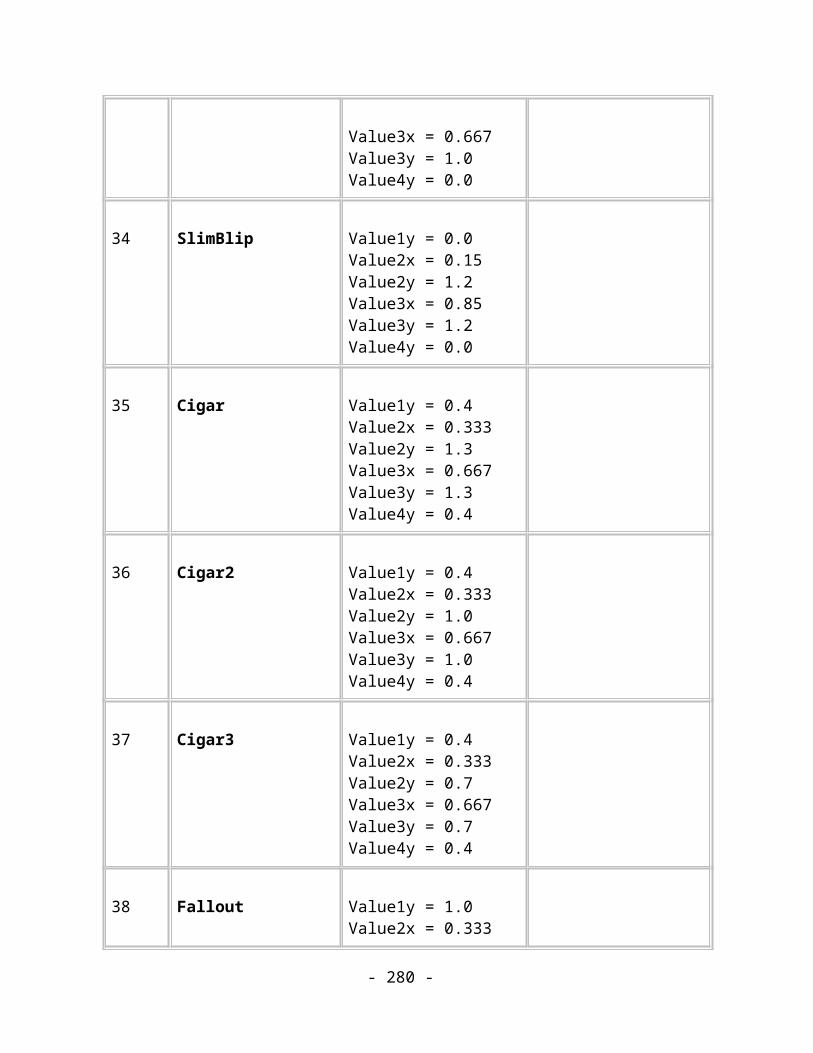
<Flags : BYTE> Bit 0: Unused, must be zeroBit 1: Set when this locked effect can be converted to a live effectBits 2-7: Unused, must be zero
<DPI : DOUBLE> Pixels per inch value for this effect. May be 0 in which case the resolution of the effect will be obtained from the objects around it and global settings.
<Bitmap : BITMAPREF>
A reference to the bitmap record containing the bitmap.
<BottomLeft : COORD>
Position of bottom left corner of bitmap in the document
<BottomRight : COORD>
Position of bottom right corner of bitmap in the document
<TopLeft : COORD> Position of top left corner of bitmap in the document
<EffectID : String> The unique internal identifier of the effect. Guaranteed to remain constant across all installations on different platforms.
<DisplayName : String>
The name of the effect shown to the user. May be localised.
<EditsXML : String> The XML document containing the parameters for the effect. The format of this document is determined by the “Xara Picture Editor”.
Comments:
A Locked effect is linked to a bitmap effect whose parameters are stored in the XML document. Unlike a Live effect, those parameters can not be edited after the original bitmap has been created or applied to different source bitmaps.
- 280 -

A Locked effect object can contain child objects in the same way as a group and the bitmap effect is applied to those objects but the child objects are hidden by the locked effect bitmap. The child objects will become visible again if the user chooses to remove or recreate the locked effect. To render a locked effect, you simply need to render the bitmap data described by the locked effect record. Xara X allows the user to convert live effects to locked effects and so locked effects can be produced by Photoshop plugins, Xara X or Xara Picture Editor.
The DPI should be used to control the resolution of the bitmap if it is recreated. If it’s zero, then the resolution should be taken from any parent effects, child effects or child bitmaps. The exact algorithm is beyond the scope of this document.
The three coordinates describe a parallelogram into which the bitmap should be rendered, allowing for 2D affine transformations.
The content of the EffectID string is managed by Xara Picture Editor.
The content of the DisplayName string is managed by Xara Picture Editor.
The content of the EditsXML string is managed by Xara Picture Editor.
Further information about any of these things can be supplied on request.
Name Feather Effect
Purpose This record describes a Feather Effect object.
Tag TAG_FEATHER_EFFECT
Size Variable
Usage Image. Compulsory.
Data:
<Flags : BYTE> Unused, must be 0
- 281 -

<DPI : DOUBLE> Pixels per inch value for this effect. May be 0 in which case the resolution of the effect will be obtained from the objects around it and global settings.
<EffectID : String> The unique internal identifier of the effect. Guaranteed to remain constant across all installations on different platforms. (Always “Camelot/Internal/Feather”)
<DisplayName : String>
The name of the effect shown to the user. May be localised.
<FeatherSize : MILLIPOINT>
The feather distance.
<FeatherProfile : PROFILE>
The profile definition describing transparency change across the feather distance.
Comments:
A Feather effect is similar in operation to a Feather attribute. The difference is that the feather effect can be used in a stack of other effects at a controlled position and will correctly feather any effect bitmaps. (The feather attribute cannot feather transparent bitmaps correctly.)
A Feather effect object can contain child objects in the same way as a group and the feather effect is applied to those objects. To render a feather effect, you must make the child objects render into a bitmap, pass the bitmap to the feather processor then render the resulting bitmap into the document.
The DPI should be used to control the resolution of the bitmap. If it’s zero, then the resolution should be taken from any parent effects, child effects or child bitmaps. The exact algorithm is beyond the scope of this document.
The content of the EffectID string is always “Camelot/Internal/Feather”
The content of the DisplayName string is usually “Feather” but may be localised.
Further information about any of these things can be supplied on request.
- 282 -
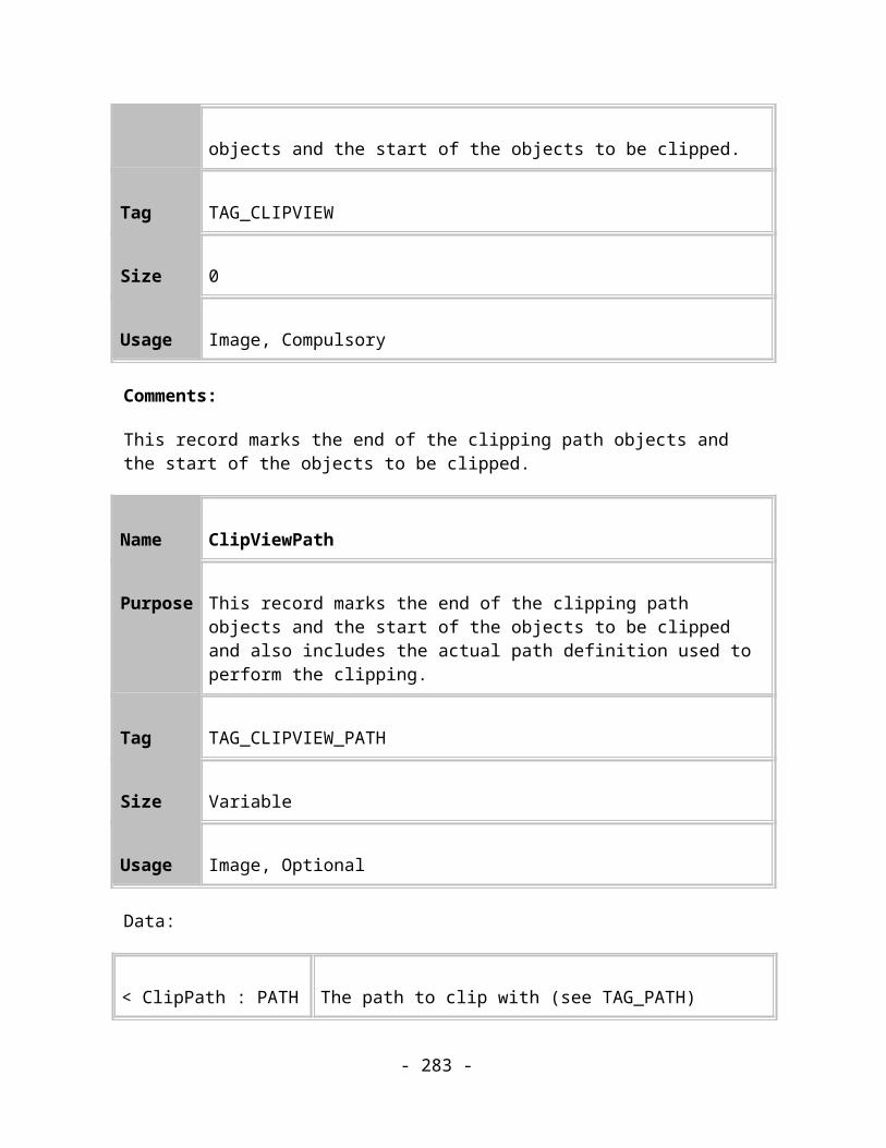
Other Image RecordsThis section covers a few records that are required to be able to render images properly but which don’t fall naturally into any of the other groups of records.
Name Group
Purpose This record defines the start of a new group.
Tag TAG_GROUP
Size 0
Usage Image. Compulsory.
Comments:
This record defines a new group. It allows a number of objects to be grouped together into one composite unit. It is always directly followed by a TAG_DOWN. All the following records until the matching TAG_UP are members of the Group.
See also: TAG_COMPOUNDRENDER
Name Quality
Purpose This record sets the current rendering quality.
Tag TAG_QUALITY
Size 4
- 283 -

Usage Image. Optional.
Data:
< Quality : INT32 > The quality level at which to render objects.
Comments:
This record applies rendering Quality as an attribute so that it can be changed on an object-by-object basis. See TAG_VIEWQUALITY for a description of the possible values the Quality field can take. Rendering Quality is really only a speed vs. accuracy trade-off and so a Renderer can safely ignore it, rendering the image at whatever quality level it thinks is appropriate.
Name Set Sentinel
Purpose This record acts as a container for various document property records.
Tag TAG_SETSENTINEL
Size 0
Usage Image. Optional.
Comments:
This record hold document property records for object naming and button bars.
- 284 -
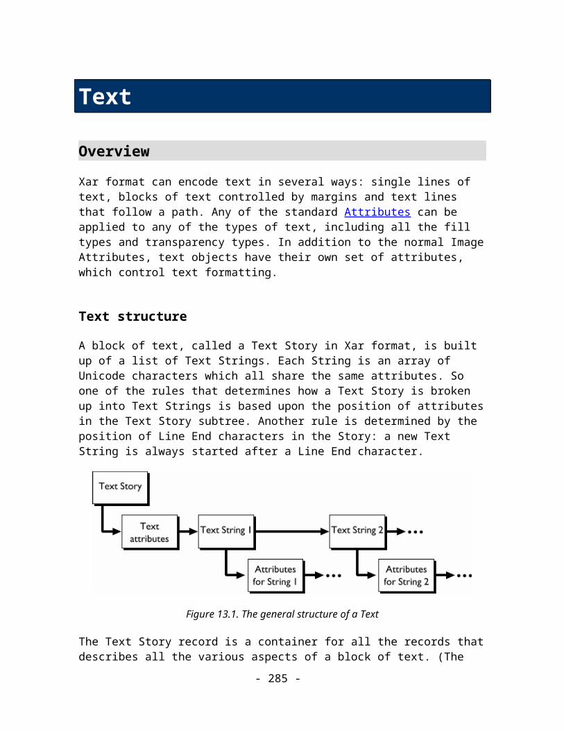
Name Wizard Property
Purpose This record can hold a range of different properties.
Tag TAG_WIZOP
Size Variable
Usage Image. Optional.
Data:
< Name : STRING > The property name. Max. 64 characters.
< Question : STRING > The question associated with this property. Max. 256 characters.
< Parameter : STRING > The parameter associated with this property. Max. 256 characters.
< Reserved : STRING > Reserved for future use. Max. 256 characters.
Comments:
This record holds a property of an object. The primary use is for naming objects where the Name value is set to “ObjectName”, the Question will be empty and the Parameter will be set to the object name.
Name Set Property
- 285 -

Purpose This record holds properties of object names.
Tag TAG_SETPROPERTY
Size Variable
Usage Image. Optional.
Data:
< Name : STRING > The object name this property set refers to.
< Count : INT16 > The number of properties contained in this record.
< Property List > A list of all the properties.
< Property List > ::= < Property >+
< Property > ::= < Index : INT16 > < Data >
Comments:
This record holds properties of an object name.
Name Bar Property
Purpose This holds properties of button bars.
Tag TAG_BARPROPERTY
- 286 -
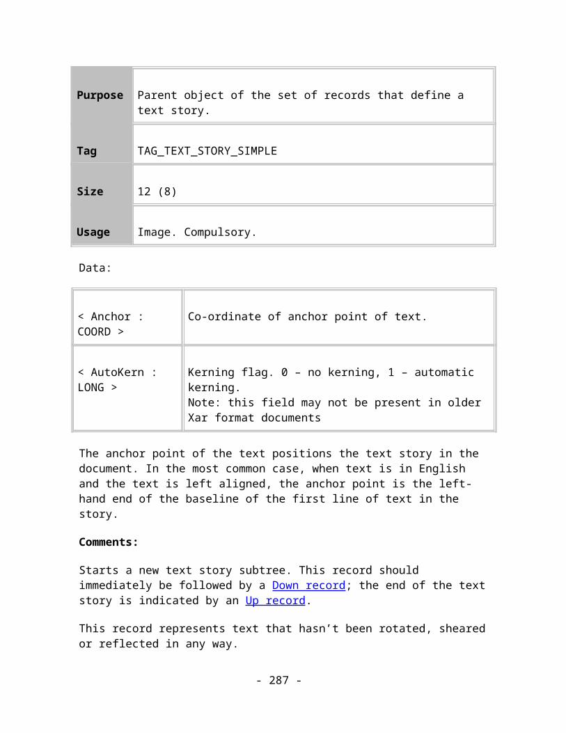
Size Variable
Usage Image. Optional.
Data:
< Count : INT32 > The number of bar property entries (one for each bar in the document).
< Property List > A list of all the bar properties.
< Property List > ::= < Bar Property >+
< Bar Property > ::= < Spacing : MILLIPOINT > < Flags : BYTE > < SameSize : BYTE >
Flags := <IsLive : BIT(0)> <IsHorizontal : BIT(1)> <NeedShuffle: BIT(2)> <ButtonsExtend: BIT(3)> <ButtonsScale: BIT(4)> <GroupsStretch: BIT(5)>
Comments:
This record holds properties of button bars.
Name Object Bounds
Purpose Holds the bounding rectangle of an object
Tag TAG_OBJECTBOUNDS
Size 16
- 287 -
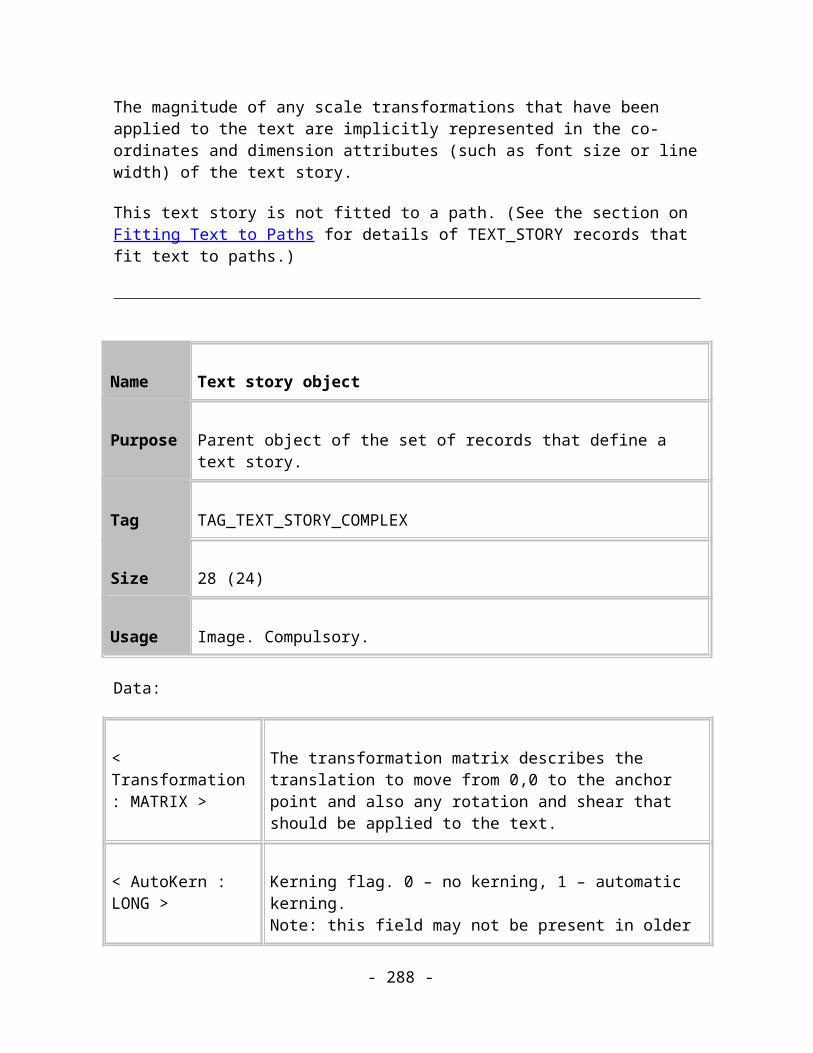
Usage Image. Optional.
Data:
< BottomLeft : COORD > The bottom left corner of the bounding rectangle
< TopRight : COORD > The top right corner of the bounding rectangle
Comments:
This record was introduced for the plugin export filter mechanism in Xara Xtreme. A filter can ask that object bounds are output either for all objects, only for compound objects or for no objects. This record is output as the first child of the object (if the object outputs additional information records before its children then it may not be the first record after the TAG_DOWN but it will be before any child objects or attributes) if the bounding box is not already output using another record (e.g. group transparency outputs a TAG_COMPOUNDRENDER record instead).
Name Compound Render Hint
Purpose This record signals that compound rendering should start and holds the bounding rectangle of the source objects
Tag TAG_COMPOUNDRENDER
Size 20
Usage Image. Optional.
Data:
- 288 -

< Reserved : UINT32 > Reserved for future use
< BottomLeft : COORD > The bottom left corner of the bounding rectangle
< TopRight : COORD > The top right corner of the bounding rectangle
Comments:
This record is used in conjunction with records representing objects that capture the images of their child objects as a bitmap and then process that bitmap in some way before rendering it into the document.
For instance, compound rendering allows Photoshop plugins to be applied to objects and allows a group of objects to be opaque to each other but transparent to the rest of the drawing.
NOTE: The following descriptions assume that compound images will be captured as bitmaps. Certain file format filters may not need to use bitmaps to implement group transparency if their target format supports distinct rendering contexts (e.g. PostScript).
The TAG_COMPOUNDRENDER record was introduced in Xara Xtreme to signal that the records in a compound object should be rendered into a bitmap. The bitmap should then either be rendered into the document using the current attributes or processed before being rendered into the document, depending on the type of compound object.
If there’s an effect transparency attribute in scope when the bitmap is rendered the bitmap should be rendered transparently. Effect transparency attributes are normal transparency attributes, with normal scoping rules, but stored in a different position in the tree than normal attributes. That different position marks them as effect transparency attributes.
TAG_COMPOUNDRENDER will always appear immediately after the TAG_DOWN record of the parent compound record and all further records until the TAG_UP should be rendered into a bitmap. The bitmap should be sized according to the BottomLeft and TopRight parameters and DPI information from the parent record.
When the TAG_UP record is encountered rendering into the bitmap can be turned off and the parent record handler can process and render the bitmap. (See TAG_LIVE_EFFECT, TAG_LOCKED_EFFECT, TAG_FEATHER_EFFECT).
The compound records affected are:
TAG_GROUP
- 289 -
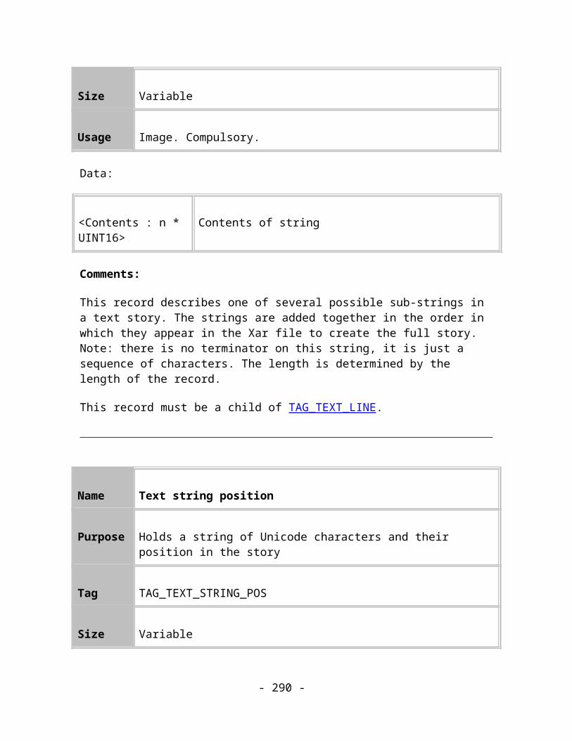
TAG_LIVE_EFFECT
TAG_LOCKED_EFFECT
TAG_FEATHER_EFFECT
TAG_BLEND
TAG_CLIPVIEWCONTROLLER
Note that compound rendered records can be nested. So, for instance, it’s possible to find several TAG_LIVE_EFFECT records in a “stack” – each one containing another TAG_LIVE_EFFECT record. The visible effect of this is that the object at the bottom of the stack is rendered, then the first effect is applied to it, then the next effect is applied to the result of the first effect, etc… up to the top effect.
TAG_GROUP
Use TAG_COMPOUNDRENDER as a signal to start rendering into a bitmap. Suggestion: Set a flag in the group record so that when the group is rendered, after all of its children, it can render the bitmap using the current effect transparency attribute.
The TAG_COMPOUNDRENDER record will only appear in groups that have an effect transparency attribute applied to them. Normal groups will not contain a TAG_COMPOUNDRENDER record.
TAG_LIVE_EFFECT, TAG_LOCKED_EFFECT, TAG_FEATHER_EFFECT
Use TAG_COMPOUNDRENDER as a signal to start capturing further rendering into a bitmap. When the effect record itself is finally rendered, it should apply the appropriate effect to the captured bitmap and then render that into the document using any effect transparency attribute in scope. The TAG_COMPOUNDRENDER record will always appear along with effect records.
TAG_BLEND, TAG_CLIPVIEWCONTROLLER
Use TAG_COMPOUNDRENDER in a similar way to TAG_GROUP.
Like Groups, the TAG_COMPOUNDRENDER record will only appear when an effect transparency attribute is applied.
- 290 -

Application RecordsThese are records that contain useful information about the document which isn’t necessary for its correct rendering. They are mainly concerned with preserving information needed by editing applications on behalf of the user.
Name Document Comment
Purpose This record stores a comment string usually entered by the user.
Tag TAG_DOCUMENTCOMMENT
Size Variable
Usage Application. Optional.
Data:
< DocumentInformation : STRING >
A comment string.
Comments:
This record is designed to store comments that the user has applied to the document. It’s only present if the user has supplied a comment, otherwise it’s omitted.
Like the preview bitmap records, it is suggested that this record should be at the start of the file, in the uncompressed section, so that programs can read it without having to understand the Xar format too deeply. This record can be used by search programs, which can pick keywords out of the comment.
Spread information
The following records contain information relating to the current spread and appear after a Spread record in the Xar format.
- 291 -
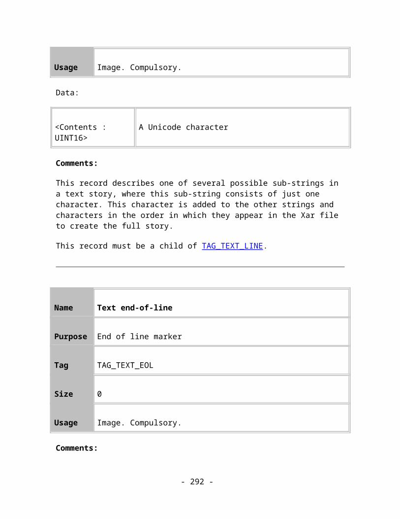
Name Spread scaling active
Purpose This record defines a current active spread scaling factor.
Tag TAG_SPREADSCALING_ACTIVE
Size 24
Usage Application. Optional.
Data:
< DrawingScale : DOUBLE >
The scaling to be applied when working in drawing mode in terms of the drawing units.
< DrawingUnits : UNITSREF >
The drawing units to use.
< RealScale : DOUBLE > The scaling to be applied when working in real world mode in terms of the real world units.
< RealUnits : UNITSREF > The real world units to use.
Comments:
This record describes a spread scaling active record. This defines the spread scaling to be used when showing the user measurements and specifies that this scaling is active now.
The record relates the actual size of the objects on the page to the scaled sizes that the drawing is intended to represent in the real world. For example, the user can define that 1cm on the drawing is equivalent to 5 miles in the real world.
- 292 -

Name Spread scaling inactive
Purpose This record defines a current inactive spread scaling factor.
Tag TAG_SPREADSCALING_INACTIVE
Size 24
Usage Application. Optional.
Data:
< DrawingScale : DOUBLE >
The scaling to be applied when working in drawing mode in terms of the drawing units.
< DrawingUnits : UNITSREF >
The drawing units to use.
< RealScale : DOUBLE > The scaling to be applied when working in real world mode in terms of the real world units.
< RealUnits : UNITSREF > The real world units to use.
Comments:
This record describes a spread scaling active record. This defines the spread scaling to be used when showing the user measurements and says that this is inactive.
Name Grid and Page Ruler settings
- 293 -
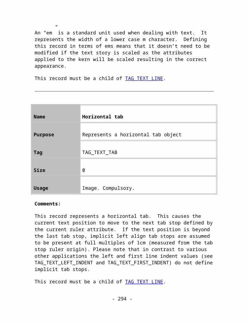
Purpose This record defines the current grid and page ruler settings.
Tag TAG_GRIDRULERSETTINGS
Size 17
Usage Application. Optional.
Data:
< GridUnits : UNITREF > The units used by the grid page ruler
< GridDivisions : DOUBLE >
The distance between each major grid & ruler graticule, measured in the units defined by GridUnits.
< GridSubDivisions : UINT32 >
The number of sub-divisions between each major grid & ruler graticule, defining the minor graticules.
< GridType : BYTE > The type of grid in use.
Grid Type Value
Rectangular 1
Orthogonal 2
Comments:
This record describes how the grid and the ruler are scaled. They both work from the same measurements which are defined in terms of the size of the main divisions in a specified
- 294 -
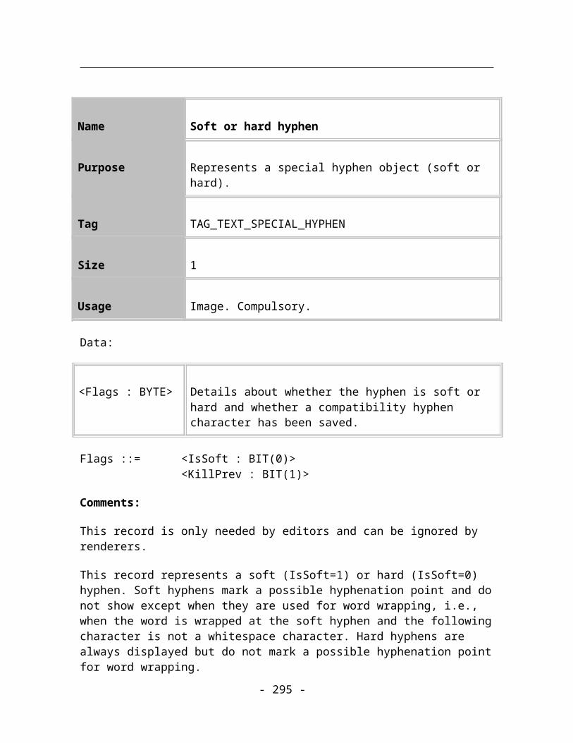
unit of measurement and the sub-divisions of these main ones. These are the unscaled sizes i.e. before any scaling has been applied.
Name Grid and Ruler Origin
Purpose This record defines the origin of the current grid and page ruler.
Tag TAG_GRIDRULERORIGIN
Size 8
Usage Application. Optional.
Data:
< GridOrigin : COORD >
The position of the origin of the grid, relative to the current origin (usually the bottom left had corner of the union of the pages).
Comments:
This record defines the current origin of the grid and page ruler relative to the bottom left hand corner of the union of the pages. The default is 0,0, so this record only needs to be present if the origin is not 0,0.
Name Nudge Offset
Purpose This record defines the offset used when nudging objects.
- 295 -

Tag TAG_DOCUMENTNUDGE
Size 4
Usage Application. Optional.
Data:
< Size : MILLIPOINT >
The distance that a single “nudge” operation will move an object.
Comments:
This record defines the distance that an object should move when “nudged” (in Xara X¹ the selection can be nudged with the cursor keys). No default value is defined in the Xar format so it is up to the application concerned (Xara X¹ uses a default of 2835 which is equivalent to 1mm).
Name Duplication Offset
Purpose This record defines the offset used when duplicating objects.
Tag TAG_DUPLICATIONOFFSET
Size 8
Usage Application. Optional.
Data:
- 296 -

< Offset : COORD > The offset to use when creating duplicate objects.
Comments:
This record defines the offset that should be used when duplicating objects (Ctrl+D in XaraX¹). No default value is defined in the Xar format so it is up to the application concerned.
Extra Document Information
The following records all contain extra non-essential information about the current document and, when present, appear directly after the Document record.
Name Document Dates
Purpose This record stores dates and times relevant to the document being processed.
Tag TAG_DOCUMENTDATES
Size 8
Usage Application. Optional.
Data:
< Creation date : DATETIME >
The date and time the document was created.
< Last saved date : DATETIME >
The date and time the document was last saved.
DATETIME ::= ANSI time_t type (same size as an UINT32)
- 297 -

Comments:
This record stores basic time information about the document.
Name Document Flags
Purpose This record stores flag information on the present document.
Tag TAG_DOCUMENTFLAGS
Size 4
Usage Application. Optional.
Data:
< Document Flags : UINT32 >Bit 0 : Multilayer flag
Bit 1 : All Layers visible flag
All other flags reserved, as set to 0.
Comments:
This record stores some flags for the document such as whether all layers are visible and whether multi-layer editing is enabled.
Name Document Structure Information
- 298 -

Purpose This record stores information about the chapters and spreads in the document
Tag TAG_DOCUMENTINFORMATION
Size Variable
Usage Application. Optional.
Data:
< Document Structure Flags : UINT16 >
All flags reserved, set to 0.
< NumChapters : UINT32 > The number of chapters in this document
And for each chapter, in the order that chapters appear in the stream:
< Chapter Structure Flags : UINT16 >
All flags reserved, set to 0.
< NumSpreads : UINT32 > The number of spreads in this document
Comments:
This record stores information about the upcoming structure of the document and is guaranteed to appear before the first Chapter record in the document. This gives Readers early notice how how many chapters and spreads it will subsequently have to read and help it to make early decisions if merging XAR files together.
Name Undo Size
- 299 -

Purpose This record stores the undo buffer size for the document.
Tag TAG_DOCUMENTUNDOSIZE
Size 4
Usage Application. Optional.
Data:
< UndoSize : UINT32 > The size of the undo buffer for the document.
Comments:
This record defines the size of the undo buffer allocated in this document. If the UndoSize value is equal to the maximum value of an UINT32 then it is considered infinite.
Name Document View
Purpose This record describes a document view object. There can be several document views onto a single document.
Tag TAG_DOCUMENTVIEW
Size 24
Usage Application. Optional.
Data:
- 300 -

< ScaleFactor : FIXED16 > Current scaling factor applied to the View.
< BottomLeft : COORD > Bottom-left co-ordinate of the view area
< TopRight: COORD > Top-right co-ordinate of the view area
< ViewFlags : UINT32 > Bit 0: BackgroundRender : 1 if background renderingBit 1: GridShow : 1 if grid is shownBit 2: GridSnap : 1 if grid is activeBit 3: ObjectsSnap : 1 if snapping to all objects is activeBits 4-7: Reserved. Must be 0.Bit 8: MagObjectsSnap : 1 if snapping to magnetic objects is activeBit 9: PrintBorderShow : 1 if print borders are shownBit 10: GuidesSnap : 1 if snapping to objects in guide layersBit 11: GuidesShow : 1 if showing objects in guide layers Bits 12-15: Reserved. Must be 0.Bit 16: ShowScrollBars : 1 if scroll bars are required on this view.Bit 17: ShowRulers : 1 if rulers are required on this view.Bits 18-31: Reserved. Must be 0.
Comments:
Defines a view onto the document in terms of a viewport onto the document, the scale that it is being shown at, plus flags that dictate the properties of this view.
Note that the BottomLeft and TopRight co-ordinates are always relative to the first spread in the document.
Name Export Hint
Purpose This record stores the user’s last used bitmap export options.
- 301 -

Tag TAG_EXPORTHINT
Size Variable
Usage Application. Optional.
Data:
< Type : UINT32 > Specifies the type of bitmap export filter1 – JPEG2 – GIF3 – PNG
< Width : UINT32 > Width of the bitmap in pixels
< Height : UINT32 > Height of the bitmap in pixels
< BPP : UINT32 > Bits per pixel
< Options : ASCII_STRING > Type specific options
Comments:
This record stores the last settings used to export a bitmap in JPEG, GIF or PNG format. The Options string is dependent on the type of filter:
JPEG – “Q<quality value> D<dpi> [P]”The quality value can range from 0 to 100.The P signifies a progressive JPEG if present.
GIF and PNG – “D<dither type> [ P<palette type> N<number of colours> [S] ] [T] [I]”Dither type can be: 0 – simple, 1 – ordered, 2 – ordered grey, 3 – error diffused, 4 – noneThe P, N and S options are only present if the BPP is less than or equal to 8Palette type can be: 0 – standard, 1 – optimised, 2 – browser, 3 – global optimised, 4 – websnap optimisedNumber of colours is the number of colours in the palette. This allows the palette to be
- 302 -

smaller than that allowed by the BPP settingThe S option indicates that the system colours should be added to the paletteThe T option indicates a transparent bitmapThe I option indicates an interlaced bitmap
Name Document Bitmap Smoothing
Purpose This record stores bitmap smoothing settings for the document.
Tag TAG_DOCUMENTBITMAPSMOOTHING
Size 5
Usage Application. Optional.
Data:
< Flags : BYTE > Bit 0 : Enable bitmap smoothingBits 1-7 : Reserved, must be set to 0
< Reserved1 : BYTE > Reserved, must be set to 0
< Reserved2 : BYTE > Reserved, must be set to 0
< Reserved3 : BYTE > Reserved, must be set to 0
< Reserved4 : BYTE > Reserved, must be set to 0
Comments:
This record stores settings relating to bitmap smoothing (interpolation).
- 303 -
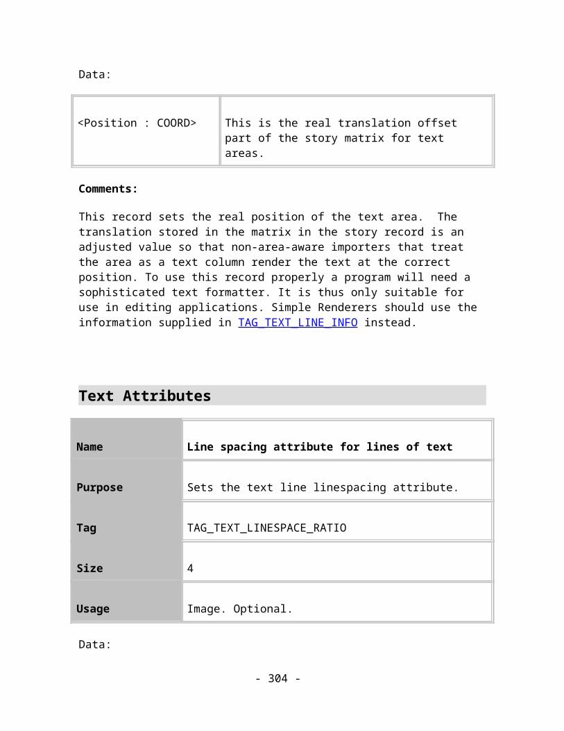
Printing information
This section describes the format of all printer options related records.
Name Printer Settings
Purpose This record describes the printer settings for this document.
Tag TAG_PRINTERSETTINGSTAG_PRINTERSETTINGS_PHASE2
Size 45 for TAG_PRINTERSETTINGS(Variable for TAG_PRINTERSETTINGS_PHASE2)
Usage Application. Optional
Data:
< NumberOfCopies : UINT32 >
The number of copies to be printed.
< PrintScale : FIXED16 > The scale to be applied to the printed document, as a percentage of the actual size.
< TopMargin : MILLIPOINTS >
The width of the margin to leave at the top of the printed page.
< LeftMargin : MILLIPOINTS >
The width of the margin to leave at the left hand side of the printed page.
< Width : MILLIPOINTS > When FitType is Custom fit, this is the page width to use.
< Height : MILLIPOINTS > When FitType is Custom fit, this is the page height to use.
- 304 -

< Rows : UINT16 > When the FitType is Multiple fit, this is the number of copies of the document to fit down the page.
< Columns : UINT16 > When the FitType is Multiple fit, this is the number of copies of the document to fit across the page.
< Gutter : MILLIPOINTS > When the FitType is Multiple fit, this is the width of the gap to apply between copies of the document.
< PrintMethod : BYTE > The form of the data sent to the printer.
< ObjectPrintRange : BYTE >
The objects in the document to print.
< DPSPrintRange : BYTE > The pages in the document to print.
< PageOrientation : BYTE > The orientation applied to the page to map it onto the printed page.
< FitType : BYTE > How to arrange the document on the printed page.
< PrintLayers : BYTE > The layers in the document to print.
< PostscriptLevel : BYTE > The Postscript Language Level to be used.
< BitmapResMethod : BYTE >
The method to determine the resolution at which bitmaps should be printed.
< DotsPerInch : UINT32 > When BitmapResMethod is Manual, this determines the resolution to use for bitmaps in dots per inch.
< PrintFlags : BYTE >Bit 0: Collated : 1 if pages collated
- 305 -

Bit 1: PrintWholeSpread : 1 if the whole of a multi-page spread is to be printed on one page, otherwise each page should be on its own sheet of paper
Bit 2: PrintToFile : 1 if printing to a file rather than directly to the printer
Bit 3: PrintTextAsShapes : 1 if text should be printed as shapes
All other flags reserved, as set to 0.
Additional Data for TAG_PRINTERSETTINGS_PHASE2:As above plus:
< PrintRange : STRING > The “Page range” string that controls which pages to print in a multi-page document.
PrintMethod Value
Normal 1
Bitmap 2
Anti-aliased Bitmap 3
ObjectPrintRange Value
All objects 1
- 306 -
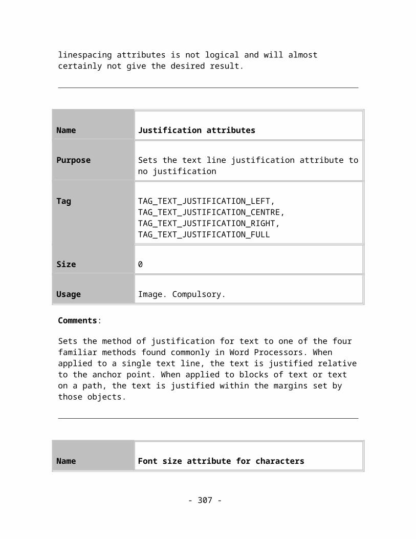
Selected objects 2
Selected pages 3
Page range 4
DPSPrintRange Value
All pages 1
Left pages 2
Right pages 3
PageOrientation Value
Portrait 1
Landscape 2
FitType Value
Best fit 1
- 307 -

Custom fit 2
Multiple fit 3
PrintLayers Value
All foreground 1
Visible foreground 2
PostscriptLevel Value
Automatic 1
Level 1 2
Level 2 3
BitmapResMethod Value
Automatic 1
Manual 2
- 308 -

Comments:
This record stores the printer settings for the document. These options typically come from the user via a “Printer Options” dialog.
The PrintRange string in TAG_PRINTERSETTINGS_PHASE2 is only used when ObjectPrintRange is 4.
Name Imagesetting Options
Purpose This record describes the document’s imagesetting options.
Tag TAG_IMAGESETTING
Size 15
Usage Application. Optional
Data:
< DeviceResolution : UINT32 > The resolution of the target printer in dots per inch.
< DefaultScreenFreq : DOUBLE >
The default screen frequency to be used in lines per inch)
< ScreenType : UINT16 > The type of screening to be used.
< ImagesettingFlags : BYTE >Bit 0: ColourSeparateOutput : 1 if printing separation plates, 0 if composite outputBit 1: UsePrinterDefaults : 1 to use printer default for screen type, otherwise use type in ScreenType fieldBit 2: EmulsionDown : 1 to print with emulsion down (reflect image in x-axis)
- 309 -

Bit 3: PhotographicNegative : 1 to negate all colour informationBit 4: AlwaysOverprintBlack : 1 to automatically overprint all CMYK colours with K > 95%Bit 5: PrintSpotsAsProcess : 1 to convert all spot colours to process colours
All other flags reserved, must be 0.
ScreenType Value
None 0
Spot 1 1
Spot 2 2
Triple spot 1 3
Triple spot 2 4
Elliptical 5
Line 6
Cross hatch 7
Mezzotint 8
Square 9
- 310 -

Dither 10
Comments:
This record stores the imagesetting options for the document. These options would usually come from the user via an advanced print options dialog.
NOTE that since this record determines the defaults for Colour Plates it must precede all TAG_COLOURPLATE records in the file.
Name Colour Plate Settings
Purpose This record describes the imagesetting options for a particular printing plate when printing colour separations of the document.
Tag TAG_COLOURPLATE
Size 22
Usage Application. Optional.
Data:
< PlateType : BYTE > The type of colour plate.
< PlateColour : COLOURREF >
0, or if PlateType is Spot, the spot colour to be printed on this plate.
< ScreenAngle : DOUBLE > The screen angle in degrees.
- 311 -

< ScreenFrequency : DOUBLE >
The screen frequency in lines per inch.
< PlateFlags : BYTE >Bit 0: PrintThisPlate : 1 if actually printing this plateBit 1: OverprintThisPlate : 1 to overprint the entire plate, otherwise knock out the plate
All other flags reserved, as set to 0.
PlateType Value
Cyan separation plate 1
Magenta 2
Yellow 3
Key 4
Spot (using PlateColour) 5
Comments:
This record stores the imagesetting options for the document. The user would usually provide these via an advanced print options dialog.
NOTE that TAG_COLOURPLATE records must always follow any TAG_IMAGESETTING record in the document to determine their default values.
Name Document Print Marks
- 312 -

Purpose This record defines the print marks to be used when printing the document.
Tag TAG_PRINTMARKDEFAULT
Size 1
Usage Application. Optional.
Data:
< PrintMark : BYTE > A number representing a print mark.
Comments:
The PrintMark refers to an application-wide print mark ID. See Appendix B for a list of the default print mark Ids.
Units
Units are used to display distances and other sizes to the user. There are by default a number of built in basic units. The user can create her own unit definitions.
The unit records usually appear after the Document record.
Defining units in terms of other units
Units within Xar files have an associated absolute distance. This distance is measured in millipoints. When defining a unit, you can give it an absolute millipoint value. However, it is sometimes more useful to be able to specify a unit in terms of another unit. A typical example is centimetres. One centimetre is always 10 millimetres, no matter how many millipoints are defined to be equal to one millimetre. If we change the number of millipoints in a millimetre, e.g., by improving the accuracy, we can automatically calculate the number of millipoints in 1 centimetre, by just multiplying the millimetre value by 10. The default set of metric units are defined this way, all based on the number of millipoints in a millimetre.
- 313 -

Here are the rules:
The first unit defined must have an absolute millipoint value, i.e., it can’t be based on another.
If a unit is based on another, the base unit must be defined beforehand.
The millipoint value for a unit based on another unit is that it is equal to:
(Millipoint value of the base unit * BaseNumerator) / BaseDenominator
Following are the record definitions for user-defined units and for the two basic measurements:
Name Define Prefix User Unit
Purpose This record declares user-defined units that are displayed before the associated value.
Tag TAG_DEFINE_PREFIXUSERUNIT,TAG_DEFINE_SUFFIXUSERUNIT
Size Variable
Usage Application. Optional.
Data:
< UnitName : STRING > The full name of the unit, e.g., “Millimetres”.
< UnitAbbreviation : STRING > The abbreviated name of the unit, e.g., “mm”.
< AbsoluteSize : UINT32 > The size of the unit in millipoints.
< BaseUnitRef : UNITSREF > The reference to the unit on which this is based. Zero
- 314 -
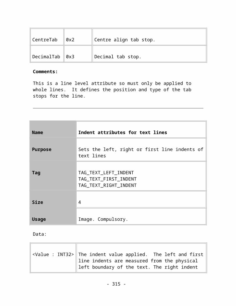
means no base unit.
< Numerator : DOUBLE > The multiplier to apply to the base unit.
< Denominator : DOUBLE > The divisor to apply to the base unit.
Comments:
Defines a new user unit.
All unit definition records should precede the TAG_DEFINE_DEFAULTUNITS record, which may reference them.
TAG_DEFINE_PREFIXUSERUNIT defines a unit whose abbreviation is shown before the numerical value, for instance, dollars, “$500”.
TAG_DEFINE_SUFFIXUSERUNIT defines a unit whose abbreviation is shown after the numerical value, for instance, metres, “500m”.
Name Define Default Units
Purpose This record defines the default units shown to users of the document.
Tag TAG_DEFINE_DEFAULTUNITS
Size 8
Usage Application. Optional.
Data:
- 315 -
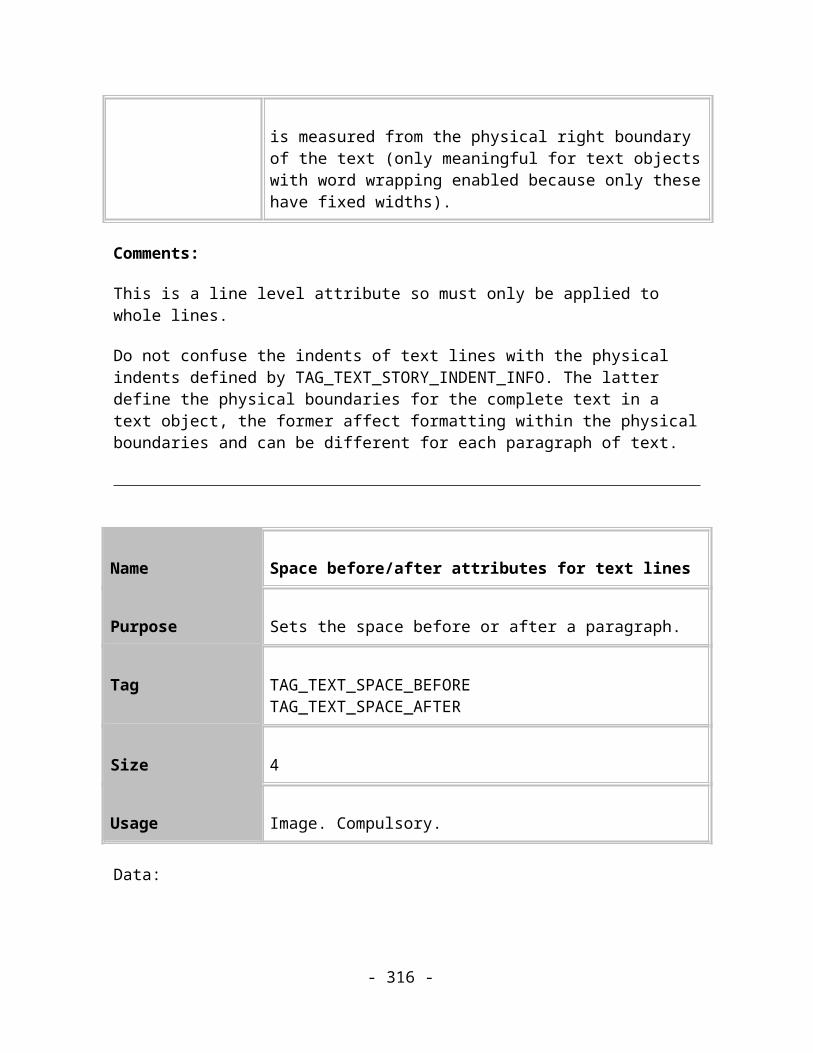
< PageUnits : UNITSREF >
A reference to the units used to display page based measurements.
< FontUnits : UNITSREF >
A reference to the units used to display font based measurements.
Comments:
This record defines the units which will be used to show measurements to the user. Two unit types are specified; Page Units for most measurements and Font Units for font sizes. Font sizes have their own unit because they are a special case – users frequently expect to see fonts measured in Points regardless of what other units other distances are measured in.
- 316 -

ExtendibilityThis chapter describes the records that allow Forward and Backward compatibility between different versions of the Xar format. Xar Readers should respond appropriately to these records. This is also discussed.
Name Atomic Records
Purpose Contains a list of tags. Records that have these tag types are defined to be atomic records
Tag TAG_ATOMICTAGS
Size Variable
Usage Extension. Compulsory where applicable
Data:
<Tag : UINT32>* Array of record Tags.
Comments:
This record is used to ensure backward compatibility of new records in old Readers. It prevents a Reader trying to understand the children of a record it doesn’t recognise.
This record contains zero or more tags. The number of tags can be calculated from the record size. There can be more than one of these records in the file, but a good Writer should only need to export one. This record should appear before the first object record in the file, although this is not a strict rule.
A record that has a tag type in this list is an ‘Atomic’ record. An atomic record is one where itself and all its children can be thought of as a single entity. Examples of atomic records are Text Stories, Moulds, and Blends.
- 317 -
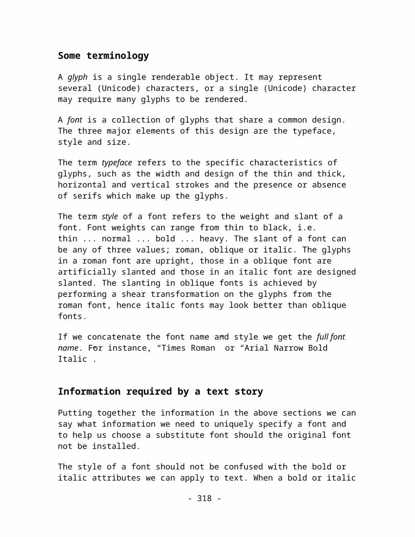
A Reader should read this record and retain the list of atomic tags for reference. When it subsequently reads a record with a tag it doesn’t understand, it should look up that tag in the list of Atomic tags. If it finds a match the record and all its child records should be ignored.
A Writer should create one of these records listing the Tags of all new records (above 1.0 format) that it writes and which it wants old Readers to treat as Atomic objects.
Note: This implies that no references should be made to tags within atomic record subtrees if the referencing record is deemed essential. For instance, TAG_PATHREF_TRANSFORM records should not reference another path in an atomic subtree.
Name Essential Records
Purpose Contains a list of tags. Records that have these tag types are defined to be essential records
Tag TAG_ESSENTIALTAGS
Size Variable
Usage Extension. Compulsory where applicable
Data:
<Tag : UINT32>* Array of record Tags.
Comments:
This record is used to ensure backward compatibility of new records in old Readers. It gives the Reader a list of Tags which it must understand if it is to display the graphic correctly.
This record contains zero or more tags. The number of tags can be calculated from the record size. There can be more than one of these records in the file, but a good Writer should only need to export one. This record should appear before the first Image record in the file, although this is not a strict rule.
- 318 -

It is assumed that all records defined as “Compulsory” in the Xar format are essential records. I.e. an importer must understand all records in v1 of the format as a minimum requirement. The Essential records mechanism is provided for future versions of the format.
A Reader should read this record and retain the list of Essential Tags for future reference. When it subsequently reads a record with a tag it doesn’t understand, it should look up that tag in the list of Essential tags. If it finds a match the Reading process should be aborted and the user should be informed. See TAG_TAGDESCRIPTION for information on informing the user.
A Writer should create one of these records listing the Tags of all new records (above 1.0 format) that it writes and which it wants old Readers to treat as being Essential to the display of the graphic.
Name Tag Descriptions
Purpose Contains a list of tags, plus a textual description of each of the tags in the list
Tag TAG_TAGDESCRIPTION
Size Variable
Usage Extension. Compulsory where applicable
Data:
< NumberOfTags : UINT32 > The Number of Tag Description fields following this field.
<Tag Description>* Array of [tag, string] pairs each describing a tag.
<Tag Description> ::= < Tag : UINT32> < Description : STRING>
Comments:
- 319 -

This record is used to ensure backward compatibility of new records in old Readers. It provides a Reader with textual names for records so that the Reader can inform the user about problem records by name. It can contain descriptions of any record but it is recommended that it only be used to describe records outside the 1.0 specification – i.e. the same records that have entries in the Atomic or Essential tables.
This record contains zero or more tags. There can be more than one of these records in the file. This record should appear before the first Image record in the file, although this is not a strict rule.
Example Tag Description entries are:
TAG_OBJECT_RECTANGLE, “Rectangle”
TAG_ATTRIBUTE_LINECOLOUR, “ “Line Colour”
TAG_PRINTMARKCUSTOM, “ TAG_PRINTMARKCUSTOM”
A Reader should read this record and retain the list of atomic tag names for reference. When it subsequently reads a record with a tag it doesn’t understand or has some other problem with, it can look up the tag’s name in this list and use the description in any message presented to the user. The Reader must not assume that a tag is named. When a tag isn’t named, the program should adjust user messages accordingly.
A Writer should create one of these records listing the Tag names of all new records (above 1.0 format) that it writes and which it wants old Readers to be able to name for the user.
- 320 -

Depreceated RecordsAs the Xar format evolves, some records may be removed from the format. This can happen for various reasons; to simplify the format, to correct problems, or to make way for improved records.
When records are deprecated in a Xar Format Revision, new Writers adhering to the revised specification will no longer create those records. New Readers adhering to the revised specification have the option of only interpreting the records in the revised spec or they can be more flexible and continue to deal with deprecated records.
When a Xar Format Revision causes some records to be deprecated there will, of course, be a lot of Xar files in the world which still contain those old records. Whether to read or write deprecated records is a decision for the implementor. It will depend upon the quantity of old format files you expect to encounter, the feature sets of the old and new revisions, the availability of other programs producing the new format, etc., etc…
Records deprecated in Version 1.0
The following records were deprecated during the development of the Version 1.0 Xar Specification. Files written by some of Xara Group Ltd.’s earlier programs (e.g. CorelXARA 1.5 and Xara Webster 1.0) may contain some of these records. Newer versions of both programs will create files that adhere to the 1.0 specification and those files will not contain any records in the list below.
Name Permutation Rectangle Records
Purpose These records describe all forms of rectangles
Tag TAG_RECTANGLE_SIMPLE_REFORMED,TAG_RECTANGLE_SIMPLE_STELLATED ,TAG_RECTANGLE_SIMPLE_STELLATED_REFORMED,TAG_RECTANGLE_SIMPLE_ROUNDED_REFORMED,TAG_RECTANGLE_SIMPLE_ROUNDED_STELLATED,TAG_RECTANGLE_SIMPLE_ROUNDED_STELLATED_REFORMED,TAG_RECTANGLE_COMPLEX_REFORMED,TAG_RECTANGLE_COMPLEX_STELLATED,TAG_RECTANGLE_COMPLEX_STELLATED_REFORMED,TAG_RECTANGLE_COMPLEX_ROUNDED_REFORMED,
- 321 -
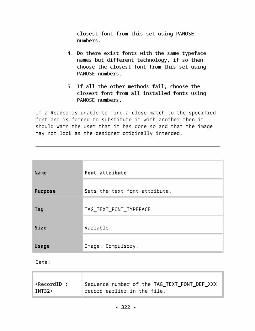
TAG_RECTANGLE_COMPLEX_ROUNDED_STELLATED,TAG_RECTANGLE_COMPLEX_ROUNDED_STELLATED_REFORMED
Size Sum of selected parts
Usage Image. Compulsory.
Data:
If not(COMPLEX and ROUNDED and REFORMED)
< Centre : COORD >
The centre point of the rectangle.
If SIMPLE
< Width : MILLIPOINTS >The radius of the horizontal axis of the bounding ellipse.
If SIMPLE
< Height : MILLIPOINTS >The radius of the vertical axis of the bounding ellipse.
If COMPLEX
< MajorAxis : COORD >The major axis point of the rectangle relative to the centre.
If COMPLEX
< MinorAxis : COORD >The minor axis point of the rectangle relative to the centre.
If COMPLEX and ROUNDED and REFORMED
< Matrix : MATRIX >
The matrix which transforms the centre of the QuickShape into position and which…
If STELLATED
< StellationRadius : DOUBLE >
The fraction of the Radius describing an ellipse on which the inner points of the star are placed.
- 322 -

If STELLATED
< StellationOffset : DOUBLE >
The angle in degrees by which the inner points of the star are offset from the outer points.
If ROUNDED
< PrimaryCurvature : DOUBLE >
The roundness of the curved corners of the rectangle.
If STELLATED and ROUNDED
< SecondaryCurvature : DOUBLE >
The roundness of the internal corners of the stellated rectangle.
If REFORMED
< EdgePath1 : PATH >The path along the edges of the rectangle or the clockwise edges of the stellated rectangle.
If REFORMED and STELLATED
< EdgePath2 : PATH >
The paths along the anti-clockwise edges of the stellated rectangle.
Comments:
As you can see from the table above, these records were unnecessarily complex and have been deprecated in favour of different flavours of TAG_POLYGON.
Note the “If” conditions in the field descriptions column! It is suggested that the Reading of these records and the more basic TAG_RECTANGLE_SIMPLE, TAG_RECTANGLE_SIMPLE_ROUNDED, TAG_RECTANGLE_COMPLEX and TAG_RECTANGLE_COMPLEX_ROUNDED records is implemented by a simple table driven algorithm.
A similar system was used to describe different permutations of polygon data fields:
Name Permutation Polygon records
- 323 -

Purpose These records describe different permutations of polygons
Tag TAG_POLYGON_COMPLEX_REFORMED,TAG_POLYGON_COMPLEX_STELLATED,TAG_POLYGON_COMPLEX_STELLATED_REFORMED,TAG_POLYGON_COMPLEX_ROUNDED_STELLATED
Size Sum of selected parts
Usage Image. Compulsory.
Data:
< NumberOfSides : UINT16 >
The number of sides the polygon has.
If not(ROUNDED and REFORMED)
< Centre : COORD >
The centre point of the polygon.
< MajorAxis : COORD > The major axis point of the polygon relative to the centre.
< MinorAxis : COORD > The minor axis point of the polygon relative to the centre.
If ROUNDED and REFORMED
< Matrix : MATRIX >
The matrix which transforms the centre of the QuickShape into position and which…
If STELLATED
< StellationRadius : DOUBLE >
The fraction of the Radius describing an ellipse on which the inner points of the star are placed.
If STELLATEDThe angle in degrees by which the inner points of the star
- 324 -

< StellationOffset : DOUBLE >
are offset from the outer points.
If ROUNDED
< PrimaryCurvature : DOUBLE >
The roundness of the curved corners of the rectangle.
If STELLATED and ROUNDED
z< SecondaryCurvature : DOUBLE >
The roundness of the internal corners of the stellated rectangle.
If REFORMED
< EdgePath1 : PATH >The path along the edges of the rectangle or the clockwise edges of the stellated rectangle.
If REFORMED and STELLATED
< EdgePath2 : PATH >
The paths along the anti-clockwise edges of the stellated rectangle.
Comments:
As you can see from the table above, these records were unnecessarily complex and have been deprecated in favour of a simpler set of TAG_POLYGON records.
Note the “If” conditions in the field descriptions column.
It is suggested that, if you choose to read these deprecated records, the Reading be implemented by a simple table driven algorithm.
Deprecated Development Quickshape records
Name Unconditional fully qualified QuickShape records
Purpose Describes a fully defined QuickShape
- 325 -

Tag TAG_REGULAR_SHAPE_PHASE_1
Size Variable
Usage Image. Compulsory.
Data:
< Flags : BYTE > Flags
<NumberOfSides : UINT> Number of sides on the QuickShape (value between 3-99)
<CentrePoint : COORD> The untransformed position of the centre
<MajorAxes : COORD> The untransformed position of the major axis
<MinorAxes : COORD> The untransformed position of the minor axis
<TransformMatrix : MATRIX>
Transform to apply to the above three points
<StellRadiusToPrimary : DOUBLE>
The value to apply to the primary radius to get the stellation to primary radius. This is the length of the inner points to the outer ones.
<StellOffsetRatio : DOUBLE>
The rotation of the inner stellation points
<PrimaryCurveToPrimary : DOUBLE>
Value to apply to the primary radius to get the primary curvature point. Defines how curved the primary curvature is.
- 326 -

<StellCurveToPrimary: DOUBLE>
Value to apply to the primary radius to get the stellation curvature point. Defines how curved the stellation curvature is.
<EdgePath1 : PATH> Primary edge
<EdgePath2 : PATH> Stellation edge (may be the same as EdgePath1).
Comments:
This record has been deprecated in favour of TAG_POLYGON_COMPLEX_ROUNDED_STELLATED_REFORMED and its simpler cousins.
Name Unconditional fully qualified QuickShape record
Purpose Describes a fully defined QuickShape
Tag TAG_REGULAR_SHAPE_PHASE_2
Size
Usage Image. Compulsory.
Data:
< Flags : BYTE > Flags
<NumberOfSides : UINT> Number of sides on the QuickShape (value between 3-99)
- 327 -
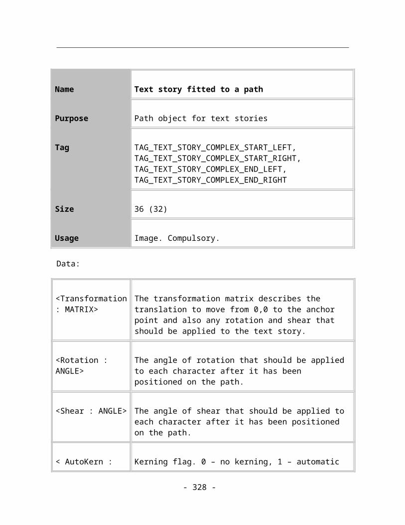
<MajorAxes : COORD> The untransformed position of the major axis
<MinorAxes : COORD> The untransformed position of the minor axis
<TransformMatrix : MATRIX>
Transform to apply to the above three points
<StellRadiusToPrimary : DOUBLE>
The value to apply to the primary radius to get the stellation to primary radius. This is the length of the inner points to the outer ones.
<StellOffsetRatio : DOUBLE>
The rotation of the inner stellation points
<PrimaryCurveToPrimary : DOUBLE>
Value to apply to the primary radius to get the primary curvature point. Defines how curved the primary curvature is.
<StellCurveToPrimary: DOUBLE>
Value to apply to the primary radius to get the stellation curvature point. Defines how curved the stellation curvature is.
<EdgePath1 : PATH> Primary edge
<EdgePath2 : PATH> Stellation edge (may be the same as EdgePath1).
Comments:
This record has been deprecated in favour of TAG_POLYGON_COMPLEX_ROUNDED_STELLATED_REFORMED and its simpler cousins.
- 328 -
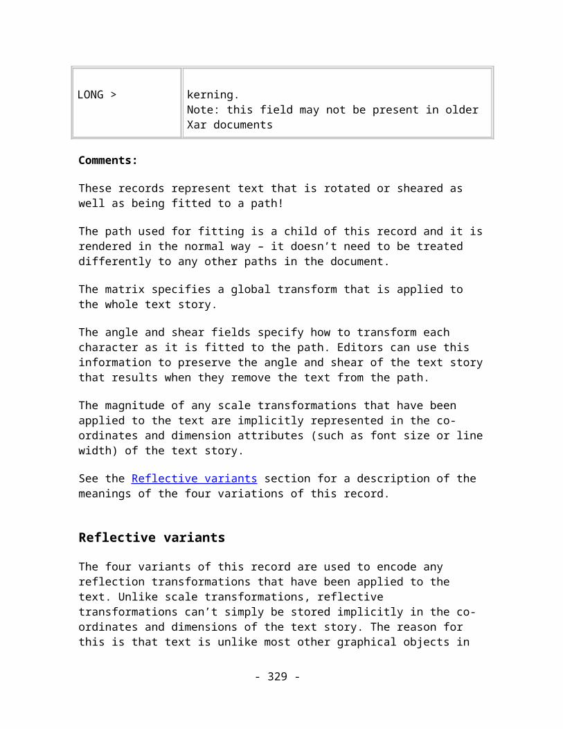
Appendix A
Complete List of Xar Tags
Tag name Tag value
Notes
//Navigation records
TAG_UP0
TAG_DOWN1
TAG_FILEHEADER2
TAG_ENDOFFILE3
// Tag management
TAG_ATOMICTAGS10
TAG_ESSENTIALTAGS11
- 329 -

TAG_TAGDESCRIPTION12
// Compression tags
TAG_STARTCOMPRESSION30
TAG_ENDCOMPRESSION31
// Document tags
TAG_DOCUMENT40
TAG_CHAPTER41
TAG_SPREAD42
TAG_LAYER43
TAG_PAGE44
- 330 -
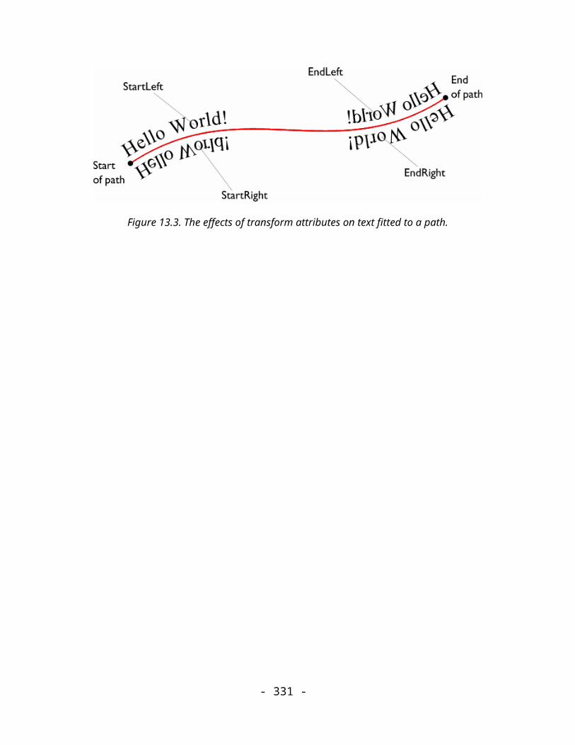
TAG_SPREADINFORMATION45
TAG_GRIDRULERSETTINGS46
TAG_GRIDRULERORIGIN47
TAG_LAYERDETAILS48
TAG_GUIDELAYERDETAILS49
TAG_SPREADSCALING_ACTIVE52
TAG_SPREADSCALING_INACTIVE53
// Colour reference tags
TAG_DEFINERGBCOLOUR50
- 331 -
TAG_DEFINECOMPLEXCOLOUR51
// Bitmap reference tags
Reserved 60
TAG_PREVIEWBITMAP_GIF61
TAG_PREVIEWBITMAP_JPEG62
TAG_PREVIEWBITMAP_PNG63
Reserved 64
Reserved 65
Reserved 66
TAG_DEFINEBITMAP_JPEG67
TAG_DEFINEBITMAP_PNG68
- 332 -

Reserved 69
Reserved 70
TAG_DEFINEBITMAP_JPEG8BPP71
// View tags
TAG_VIEWPORT80
TAG_VIEWQUALITY81
TAG_DOCUMENTVIEW82
// Document unit tags
TAG_DEFINE_PREFIXUSERUNIT85
TAG_DEFINE_SUFFIXUSERUNIT86
TAG_DEFINE_DEFAULTUNITS87
- 333 -

// Document info tags
TAG_DOCUMENTCOMMENT90
TAG_DOCUMENTDATES91
TAG_DOCUMENTUNDOSIZE92
TAG_DOCUMENTFLAGS93
TAG_DOCUMENTINFORMATION 4136
// Object tags
TAG_PATH100
TAG_PATH_FILLED101
TAG_PATH_STROKED102
- 334 -

TAG_PATH_FILLED_STROKED103
TAG_GROUP104
TAG_BLEND105
TAG_BLENDER106
TAG_MOULD_ENVELOPE107
TAG_MOULD_PERSPECTIVE108
TAG_MOULD_GROUP109
TAG_MOULD_PATH110
TAG_PATH_FLAGS111
TAG_GUIDELINE112
TAG_PATH_RELATIVE113
- 335 -

TAG_PATH_RELATIVE_FILLED114
TAG_PATH_RELATIVE_STROKED115
TAG_PATH_RELATIVE_FILLED_STROKED116
Reserved 117
TAG_PATHREF_TRANSFORM118
// Attribute tags
TAG_FLATFILL150
TAG_LINECOLOUR151
TAG_LINEWIDTH152
TAG_LINEARFILL153
TAG_CIRCULARFILL154
- 336 -

TAG_ELLIPTICALFILL155
TAG_CONICALFILL156
TAG_BITMAPFILL157
TAG_CONTONEBITMAPFILL158
TAG_FRACTALFILL159
TAG_FILLEFFECT_FADE160
TAG_FILLEFFECT_RAINBOW161
TAG_FILLEFFECT_ALTRAINBOW162
TAG_FILL_REPEATING163
TAG_FILL_NONREPEATING164
TAG_FILL_REPEATINGINVERTED165
- 337 -

TAG_FLATTRANSPARENTFILL166
TAG_LINEARTRANSPARENTFILL167
TAG_CIRCULARTRANSPARENTFILL168
TAG_ELLIPTICALTRANSPARENTFILL169
TAG_CONICALTRANSPARENTFILL170
TAG_BITMAPTRANSPARENTFILL171
TAG_FRACTALTRANSPARENTFILL172
TAG_LINETRANSPARENCY173
TAG_STARTCAP174
TAG_ENDCAP175
TAG_JOINSTYLE176
- 338 -
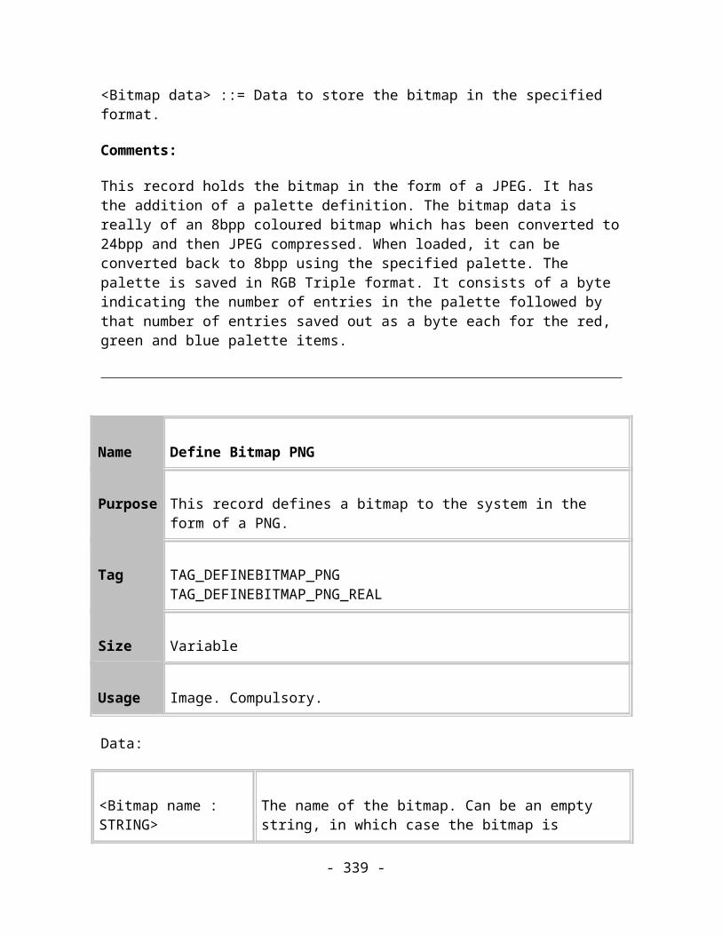
TAG_MITRELIMIT177
TAG_WINDINGRULE178
TAG_QUALITY179
TAG_TRANSPARENTFILL_REPEATING180
TAG_TRANSPARENTFILL_NONREPEATING181
TAG_TRANSPARENTFILL_REPEATINGINVERTED182
// Arrows and dash patterns
TAG_DASHSTYLE183
TAG_DEFINEDASH184
TAG_ARROWHEAD185
TAG_ARROWTAIL186
- 339 -

TAG_DEFINEARROW187
TAG_DEFINEDASH_SCALED188
// User Attributes
TAG_USERVALUE189
// special colour fills
TAG_FLATFILL_NONE190
TAG_FLATFILL_BLACK191
TAG_FLATFILL_WHITE192
TAG_LINECOLOUR_NONE193
TAG_LINECOLOUR_BLACK194
- 340 -

TAG_LINECOLOUR_WHITE195
// Bitmaps
TAG_NODE_BITMAP198
TAG_NODE_CONTONEDBITMAP199
// New fill type records
TAG_DIAMONDFILL200
TAG_DIAMONDTRANSPARENTFILL201
TAG_THREECOLFILL202
TAG_THREECOLTRANSPARENTFILL203
TAG_FOURCOLFILL204
- 341 -
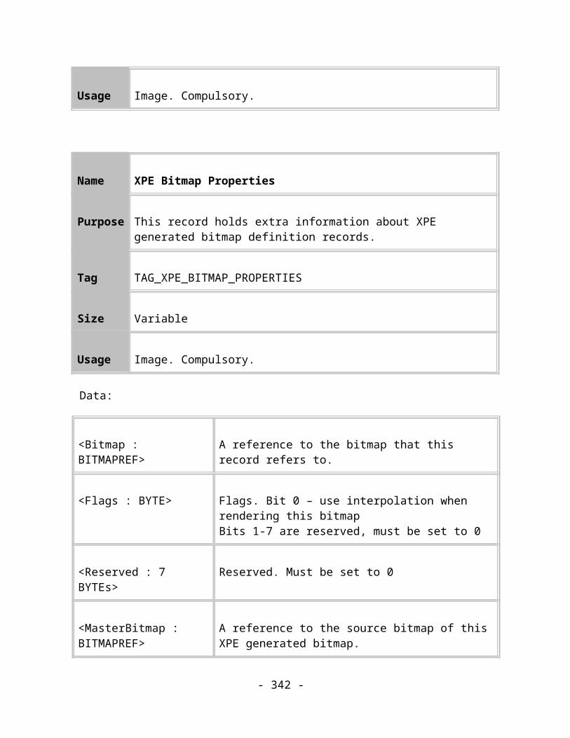
TAG_FOURCOLTRANSPARENTFILL205
TAG_FILL_REPEATING_EXTRA206
TAG_TRANSPARENTFILL_REPEATING_EXTRA207
// Regular shapes
// Ellipses
TAG_ELLIPSE_SIMPLE1000
TAG_ELLIPSE_COMPLEX1001
// Rectangles
TAG_RECTANGLE_SIMPLE1100
TAG_RECTANGLE_SIMPLE_REFORMED 1101 Deprecated
TAG_RECTANGLE_SIMPLE_STELLATED 1102 Deprecated
- 342 -
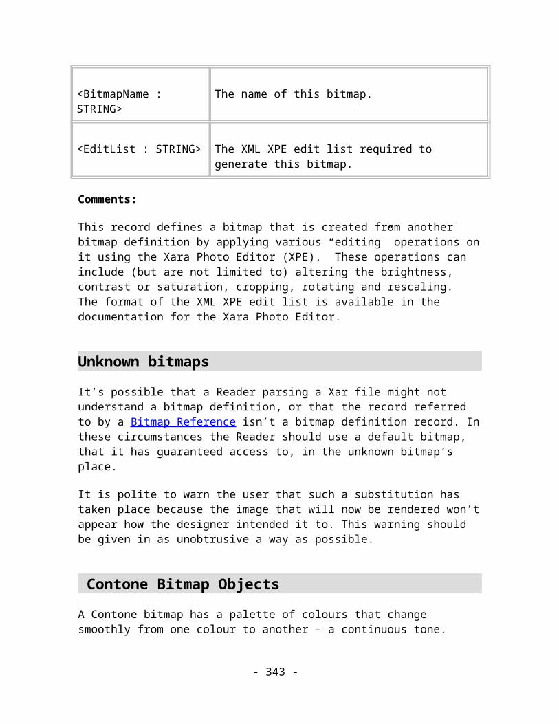
TAG_RECTANGLE_SIMPLE_STELLATED_REFORMED 1103 Deprecated
TAG_RECTANGLE_SIMPLE_ROUNDED1104
TAG_RECTANGLE_SIMPLE_ROUNDED_REFORMED 1105 Deprecated
TAG_RECTANGLE_SIMPLE_ROUNDED_STELLATED 1106 Deprecated
TAG_RECTANGLE_SIMPLE_ROUNDED_STELLATED_REFORMED 1107 Deprecated
TAG_RECTANGLE_COMPLEX1108
TAG_RECTANGLE_COMPLEX_REFORMED 1109 Deprecated
TAG_RECTANGLE_COMPLEX_STELLATED 1110 Deprecated
TAG_RECTANGLE_COMPLEX_STELLATED_REFORMED 1111 Deprecated
TAG_RECTANGLE_COMPLEX_ROUNDED1112
TAG_RECTANGLE_COMPLEX_ROUNDED_REFORMED 1113 Deprecated
TAG_RECTANGLE_COMPLEX_ROUNDED_STELLATED 1114 Deprecated
TAG_RECTANGLE_COMPLEX_ROUNDED_STELLATED_REFORMED 1115 Deprecated
- 343 -
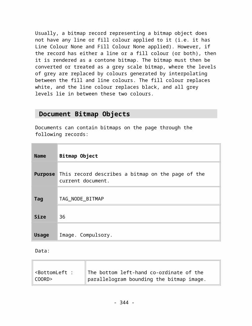
// Polygons
TAG_POLYGON_COMPLEX1200
TAG_POLYGON_COMPLEX_REFORMED 1201 Deprecated
TAG_POLYGON_COMPLEX_STELLATED 1212 Deprecated
TAG_POLYGON_COMPLEX_STELLATED_REFORMED 1213 Deprecated
TAG_POLYGON_COMPLEX_ROUNDED1214
TAG_POLYGON_COMPLEX_ROUNDED_REFORMED1215
TAG_POLYGON_COMPLEX_ROUNDED_STELLATED 1216 Deprecated
TAG_POLYGON_COMPLEX_ROUNDED_STELLATED_REFORMED1217
// General regular shapes
TAG_REGULAR_SHAPE_PHASE_1 1900 Deprecated
TAG_REGULAR_SHAPE_PHASE_2 1901
- 344 -

// Text related records
// Text definitions
TAG_FONT_DEF_TRUETYPE2000
TAG_FONT_DEF_ATM2001
// vanilla text story objects
TAG_TEXT_STORY_SIMPLE2100
TAG_TEXT_STORY_COMPLEX2101
// text story objects on a path
TAG_TEXT_STORY_SIMPLE_START_LEFT2110
TAG_TEXT_STORY_SIMPLE_START_RIGHT2111
TAG_TEXT_STORY_SIMPLE_END_LEFT2112
- 345 -

TAG_TEXT_STORY_SIMPLE_END_RIGHT2113
TAG_TEXT_STORY_COMPLEX_START_LEFT2114
TAG_TEXT_STORY_COMPLEX_START_RIGHT2115
TAG_TEXT_STORY_COMPLEX_END_LEFT2116
TAG_TEXT_STORY_COMPLEX_END_RIGHT2117
// Text story information records
TAG_TEXT_STORY_WORD_WRAP_INFO2150
TAG_TEXT_STORY_INDENT_INFO2151
// other text story related objects
TAG_TEXT_LINE2200
- 346 -

TAG_TEXT_STRING2201
TAG_TEXT_CHAR2202
TAG_TEXT_EOL2203
TAG_TEXT_KERN2204
TAG_TEXT_CARET2205
TAG_TEXT_LINE_INFO2206
// Text attributes
TAG_TEXT_LINESPACE_RATIO2900
TAG_TEXT_LINESPACE_ABSOLUTE2901
TAG_TEXT_JUSTIFICATION_LEFT2902
TAG_TEXT_JUSTIFICATION_CENTRE2903
- 347 -

TAG_TEXT_JUSTIFICATION_RIGHT2904
TAG_TEXT_JUSTIFICATION_FULL2905
TAG_TEXT_FONT_SIZE2906
TAG_TEXT_FONT_TYPEFACE2907
TAG_TEXT_BOLD_ON2908
TAG_TEXT_BOLD_OFF2909
TAG_TEXT_ITALIC_ON2910
TAG_TEXT_ITALIC_OFF2911
TAG_TEXT_UNDERLINE_ON2912
TAG_TEXT_UNDERLINE_OFF2913
TAG_TEXT_SCRIPT_ON2914
- 348 -

TAG_TEXT_SCRIPT_OFF2915
TAG_TEXT_SUPERSCRIPT_ON2916
TAG_TEXT_SUBSCRIPT_ON2917
TAG_TEXT_TRACKING2918
TAG_TEXT_ASPECT_RATIO2919
TAG_TEXT_BASELINE2920
// Imagesetting attributes
TAG_OVERPRINTLINEON3500
TAG_OVERPRINTLINEOFF3501
TAG_OVERPRINTFILLON3502
TAG_OVERPRINTFILLOFF3503
- 349 -

TAG_PRINTONALLPLATESON3504
TAG_PRINTONALLPLATESOFF3505
// Document Print/Imagesetting options
TAG_PRINTERSETTINGS3506
TAG_IMAGESETTING3507
TAG_COLOURPLATE3508
// Registration mark records
TAG_PRINTMARKDEFAULT3509
Reserved 3510
// Stroking records
TAG_VARIABLEWIDTHFUNC 4000 This record is not
- 350 -

currently used
TAG_VARIABLEWIDTHTABLE4001
TAG_STROKETYPE4002
TAG_STROKEDEFINITION 4003 This record is not currently used
TAG_STROKEAIRBRUSH 4004 This record is not currently used
// Fractal Noise records
TAG_NOISEFILL4010
TAG_NOISETRANSPARENTFILL4011
// Mould bounds record
TAG_MOULD_BOUNDS4012
// Bitmap export hint record
- 351 -
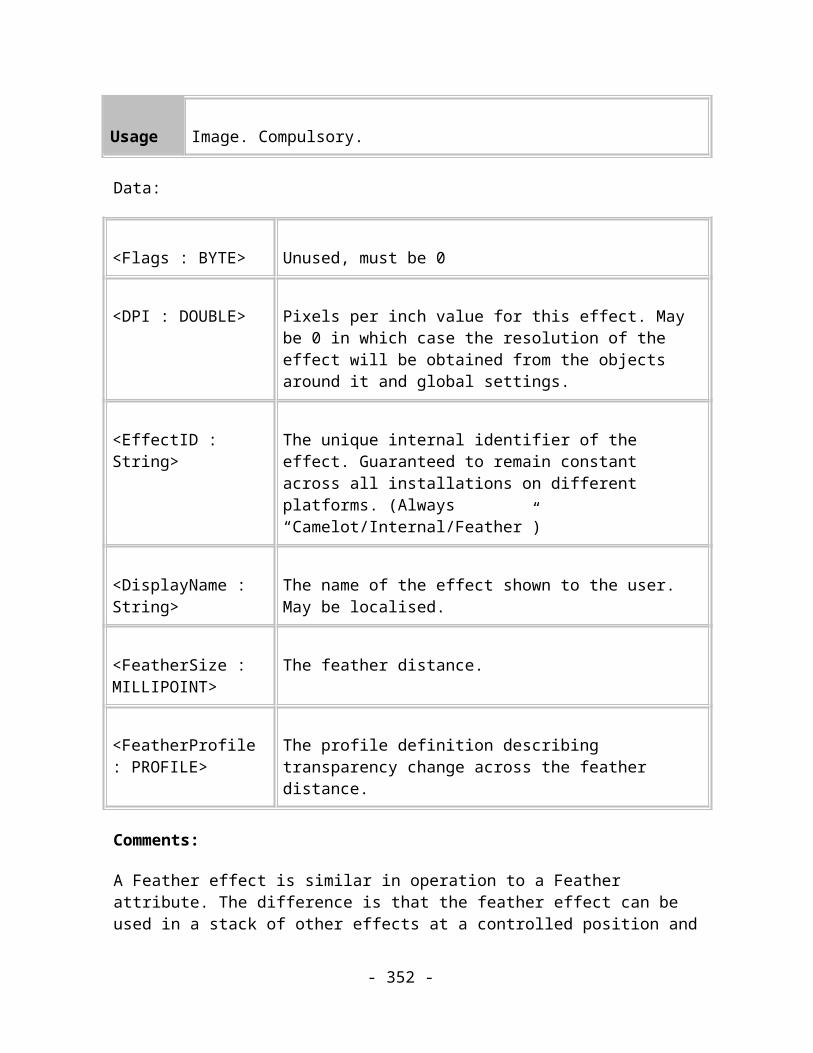
TAG_EXPORT_HINT4015
// Web Address tags
TAG_WEBADDRESS4020
TAG_WEBADDRESS_BOUNDINGBOX4021
// Frame layer tags
TAG_LAYER_FRAMEPROPS4030
TAG_SPREAD_ANIMPROPS4031
// Wizard properties tags
TAG_WIZOP4040
TAG_WIZOP_STYLE 4041
TAG_WIZOP_STYLEREF 4042
// Shadow tags
TAG_SHADOWCONTROLLER4050
- 352 -

TAG_SHADOW4051
// Bevel tags
TAG_BEVEL4052
TAG_BEVATTR_INDENT 4053 Deprecated
TAG_BEVATTR_LIGHTANGLE 4054 Deprecated
TAG_BEVATTR_CONTRAST 4055 Deprecated
TAG_BEVATTR_TYPE 4056 Deprecated
TAG_BEVELINK4057
// Blend on a curve tags
TAG_BLENDER_CURVEPROP4060
TAG_BLEND_PATH4061
TAG_BLENDER_CURVEANGLES4062
// Contouring tags
- 353 -

TAG_CONTOURCONTROLLER4066
TAG_CONTOUR4067
// Set tags
TAG_SETSENTINEL4070
TAG_SETPROPERTY4071
// More Blend on a curve tags
TAG_BLENDPROFILES4072
TAG_BLENDERADDITIONAL4073
TAG_NODEBLENDPATH_FILLED4074
// Multi stage fill tags
TAG_LINEARFILLMULTISTAGE4075
TAG_CIRCULARFILLMULTISTAGE4076
- 354 -
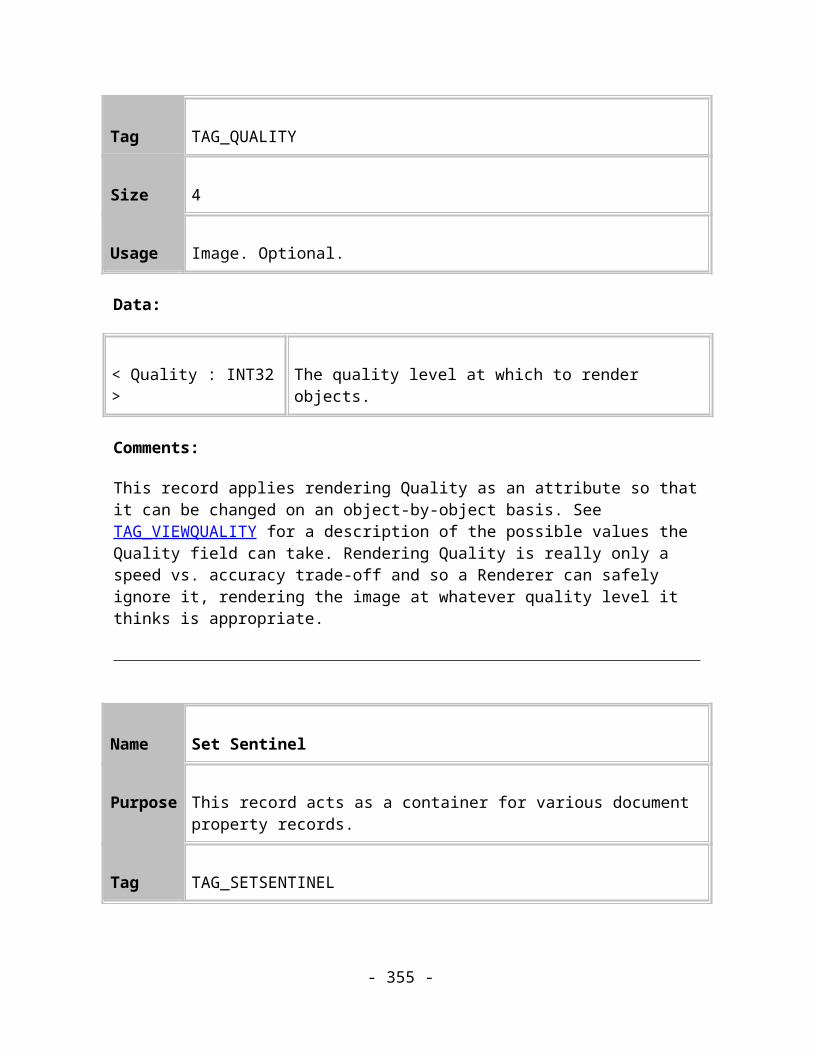
TAG_ELLIPTICALFILLMULTISTAGE4077
TAG_CONICALFILLMULTISTAGE4078
// Brush attribute tags
TAG_BRUSHATTR4079
TAG_BRUSHDEFINITION4080
TAG_BRUSHDATA4081
TAG_MOREBRUSHDATA4082
TAG_MOREBRUSHATTR4083
// ClipView tags
TAG_CLIPVIEWCONTROLLER4084
TAG_CLIPVIEW4085
// Feathering tags
- 355 -

TAG_FEATHER4086
// Bar properties tag
TAG_BARPROPERTY4087
// Other multi stage fill tags
TAG_SQUAREFILLMULTISTAGE4088
// More brush tags
TAG_EVENMOREBRUSHDATA4102
TAG_EVENMOREBRUSHATTR4103
TAG_TIMESTAMPBRUSHDATA4104
TAG_BRUSHPRESSUREINFO4105
TAG_BRUSHPRESSUREDATA 4106
TAG_BRUSHATTRPRESSUREINFO4107
- 356 -
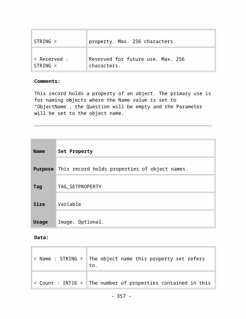
TAG_BRUSHCOLOURDATA 4108
TAG_BRUSHPRESSURESAMPLEDATA4109
TAG_BRUSHTIMESAMPLEDATA 4110
TAG_BRUSHATTRFILLFLAGS4111
TAG_BRUSHTRANSPINFO4112
TAG_BRUSHATTRTRANSPINFO4113
// Nudge size record
TAG_DOCUMENTNUDGE4114
// Bitmap properties record
TAG_BITMAP_PROPERTIES4115
// Bitmap smoothing record
TAG_DOCUMENTBITMAPSMOOTHING4116
// XPE bitmap processing record
- 357 -
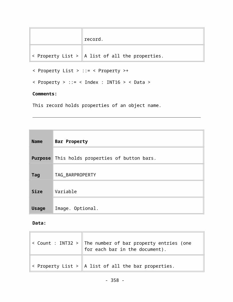
TAG_XPE_BITMAP_PROPERTIES4117
// XPE Bitmap file format placeholder record
TAG_DEFINEBITMAP_XPE4118
// Current attributes records
TAG_CURRENTATTRIBUTES4119
TAG_CURRENTATTRIBUTEBOUNDS4120
// 3-point linear fill records
TAG_LINEARFILL3POINT4121
TAG_LINEARFILLMULTISTAGE3POINT4122
TAG_LINEARTRANSPARENTFILL3POINT4123
// Duplication distance record
TAG_DUPLICATIONOFFSET4124
- 358 -

// Bitmap effect tags
TAG_LIVE_EFFECT4125
TAG_LOCKED_EFFECT4126
TAG_FEATHER_EFFECT4127
// Miscellaneous records
TAG_COMPOUNDRENDER4128
TAG_OBJECTBOUNDS4129
TAG_SPREAD_PHASE2 4131
TAG_CURRENTATTRIBUTES_PHASE2 4132
TAG_SPREAD_FLASHPROPS 4134
TAG_PRINTERSETTINGS_PHASE2 4135
TAG_DOCUMENTINFORMATION 4136
TAG_CLIPVIEW_PATH 4137
- 359 -

TAG_DEFINEBITMAP_PNG_REAL 4138
TAG_TEXT_STRING_POS 4139
TAG_SPREAD_FLASHPROPS2 4140
TAG_TEXT_LINESPACE_LEADING 4141
// New text records
TAG_TEXT_TAB 4200
TAG_TEXT_LEFT_INDENT 4201
TAG_TEXT_FIRST_INDENT 4202
TAG_TEXT_RIGHT_INDENT 4203
TAG_TEXT_RULER 4204
TAG_TEXT_STORY_HEIGHT_INFO 4205
TAG_TEXT_STORY_LINK_INFO 4206
TAG_TEXT_STORY_TRANSLATION_INFO 4207
TAG_TEXT_SPACE_BEFORE 4208
TAG_TEXT_SPACE_AFTER 4209
- 360 -
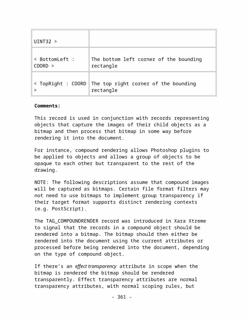
TAG_TEXT_SPECIAL_HYPHEN 4210
TAG_TEXT_SOFT_RETURN 4211
TAG_TEXT_EXTRA_FONT_INFO 4212
TAG_TEXT_EXTRA_TT_FONT_DEF 4213
TAG_TEXT_EXTRA_ATM_FONT_DEF 4214
- 361 -
Appendix B
Lists of Default Values
Default Attributes
The default attributes which are assumed to be applied to the document when tree rendering first starts.
Attribute First Value
Text Line spacing LineSpacing = 0 Ratio = 1.00
Text Baseline Rise = 0
Text Script Size = 1 Offset = 0
Text SubScript Size = 0.5 Offset = -0.1
Text SuperScript Size = 0.5 Offset = 0.33
Text Underline FALSE
Text Tracking 0
Text Justification Left justified
Text AspectRatio 1.000000
- 362 -

Text Italic FALSE
Text Bold FALSE
Text FontTypeface Font = Times New Roman
Type = TrueType
Bold = FALSE
Italic = FALSE
MitreLimit 4000
EndArrow None
StartArrow None
StartCap Butt
DashPattern REF_DASH_SOLID
Quality 110
JoinType Bevelled
WindingRule Even-odd
LineWidth 501
FillEffectFade None
TranspFillMappingLinear None
FillMappingLinear None
- 363 -

FlatTranspFill None
FlatColourFill None
StrokeTransp Fill colour = transparent
Start colour = transparent
StrokeTransparency Line Transparency = 0
Transparency Type = 1
StrokeColour Line colour = RGB(0, 0, 0)
Feather None
StrokeType 0x01000000
Default arrowheads and tails
The following arrowheads and tails are assumed to be defined as standard and hence not included in the file. As with all built-in items these defaults are referenced via a negative reference number ID.
REF_ARROW_NULL
This is the default arrow. If a defined arrow is not found then this can be chosen as the default to replace it with.
Reference Value -1
LineWidth 72000/2
Centre 0,0
- 364 -

Flags Filled ScaleWithLineWidth
Path NULL
REF_ARROW_STRAIGHT
Reference Value -2
LineWidth (72000/2)*3
Centre 0,0
Flags Filled
PathMoveTo ( -9000, 54000)
LineTo ( -9000, -54000)
LineTo (117000, 0)
ClosePath
REF_ARROW_ANGLED
Reference Value -3
LineWidth (72000/2)*3
Centre 0,0
- 365 -

Flags Filled
PathMoveTo (-27000, 54000)
LineTo ( -9000, 0)
LineTo (-27000, -54000)
LineTo (135000, 0)
ClosePath
REF_ARROW_ROUNDED
Reference Value -4
LineWidth (72000/2)*3
Centre 0,0
Flags Filled
PathMoveTo ( -9000, 0)
LineTo ( -9000, -45000)
CurveTo ( -9000, -51708), ( 2808, -56580), ( 9000, -54000)
LineTo ( 117000, -9000)
CurveTo ( 120916, -7369), ( 126000, -4242), ( 126000, 0)
CurveTo ( 126000, 4242), ( 120916, 7369), ( 117000, 9000)
LineTo ( 9000, 54000)
- 366 -
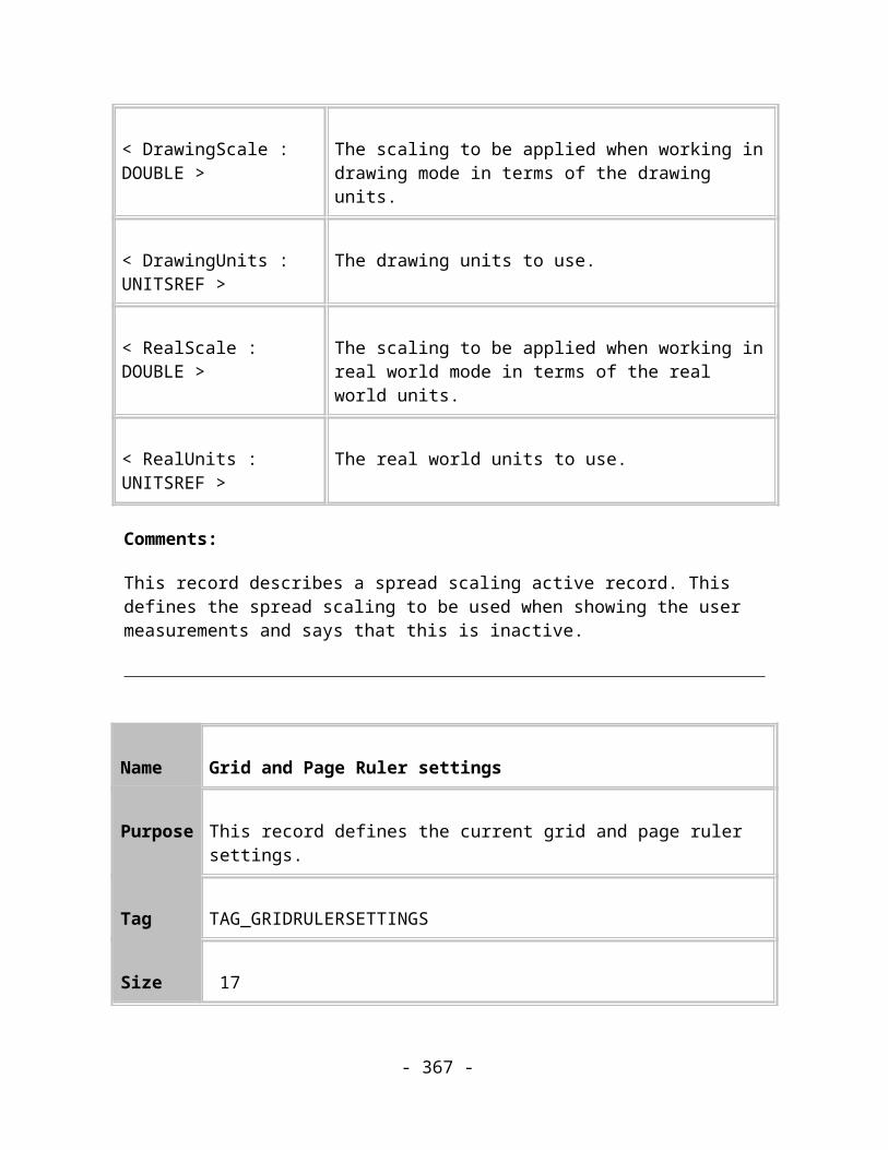
CurveTo ( 2808, 56580), ( -9000, 51708), ( -9000, 45000)
ClosePath
REF_ARROW_SPOT
Reference Value -5
LineWidth (72000/2)*3
Centre 0,0
Flags Filled, StartArrow
PathMoveTo ( -54000, 0)
CurveTo ( -54000, 29807), ( -29807, 54000), ( 0, 54000)
CurveTo ( 29807, 54000), ( 54000, 29807), ( 54000, 0)
CurveTo ( 54000, -29807), ( 29807, -54000), ( 0, -54000)
CurveTo ( -29807, -54000), ( -54000, -29807), ( -54000, 0)
ClosePath
REF_ARROW_DIAMOND
Reference Value -6
LineWidth (72000/2)*3
- 367 -

Centre 0,0
Flags Filled, StartArrow
PathMoveTo (-63000, 0)
LineTo ( 0, 63000)
LineTo ( 63000, 0)
LineTo ( 0, -63000)
ClosePath
REF_ARROW_FEATHER
Reference Value -7
LineWidth (72000/2)*3
Centre 0,0
Flags Filled, StartArrow
PathMoveTo (18000, -54000)
LineTo (108000, -54000)
LineTo ( 63000, 0)
LineTo (108000, 54000)
LineTo ( 18000, 54000)
LineTo (-36000, 0)
- 368 -
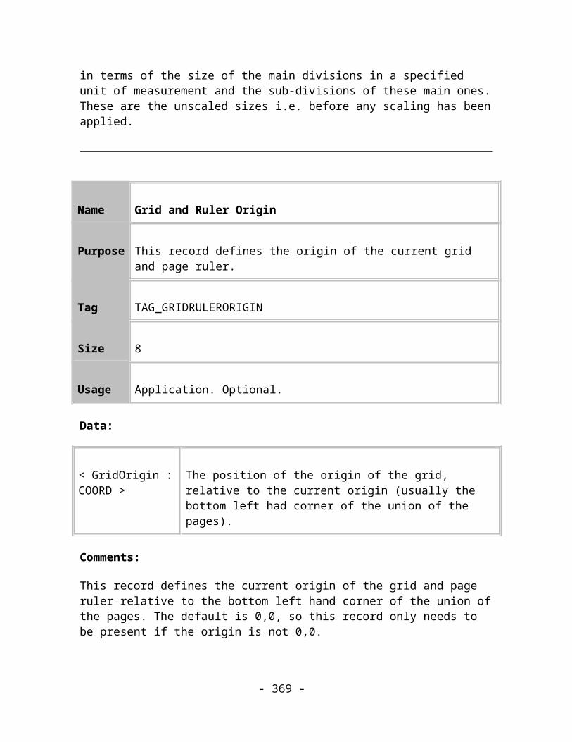
ClosePath
REF_ARROW_FEATHER2
Reference Value -8
LineWidth (72000/2)*3
Centre 0,0
Flags Filled, StartArrow
PathMoveTo( -36000, 0)
LineTo ( 18000, -54000)
LineTo ( 54000, -54000)
LineTo ( 18000, -18000)
LineTo ( 27000, -18000)
LineTo ( 63000, -54000)
LineTo ( 99000, -54000)
LineTo ( 63000, -18000)
LineTo ( 72000, -18000)
LineTo ( 108000, -54000)
LineTo ( 144000, -54000)
LineTo ( 90000, 0)
- 369 -
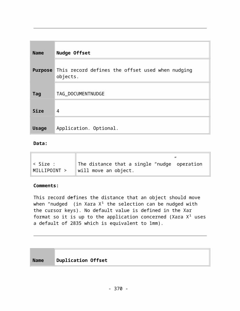
LineTo ( 144000, 54000)
LineTo ( 108000, 54000)
LineTo ( 72000, 18000)
LineTo ( 63000, 18000)
LineTo ( 99000, 54000)
LineTo ( 63000, 54000)
LineTo ( 27000, 18000)
LineTo ( 18000, 18000)
LineTo ( 54000, 54000)
LineTo ( 18000, 54000)
ClosePath
REF_ARROW_HOLLOWDIAMOND
Reference Value -9
LineWidth (72000/2)*3
Centre -45000,0
Flags Filled, StartArrow
PathMoveTo( 0, 45000)
LineTo (-45000, 0)
- 370 -

LineTo ( 0, -45000)
LineTo ( 45000, 0)
ClosePath
MoveTo( 0, 63000)
LineTo (-63000, 0)
LineTo ( 0, -63000)
LineTo ( 63000, 0)
ClosePath
Default dash patterns
The DashUnit size used in the definitions is defined to be:
const LONG DashUnit = 72000/4;
REF_DASH_SOLID
Reference Value -21
DashStart 0
LineWidth 72000/4
DashFlags ScaleWithLineWidth
Elements 0
- 371 -

DashDef NULL
This is the default pattern.
REF_DASH_1
Reference Value -1
DashStart 0
LineWidth 72000/4
DashFlags ScaleWithLineWidth
Elements 2
DashDefDashUnit*2
DashUnit*2
REF_DASH_2
Reference Value -2
DashStart 0
LineWidth 72000/4
DashFlags ScaleWithLineWidth
- 372 -
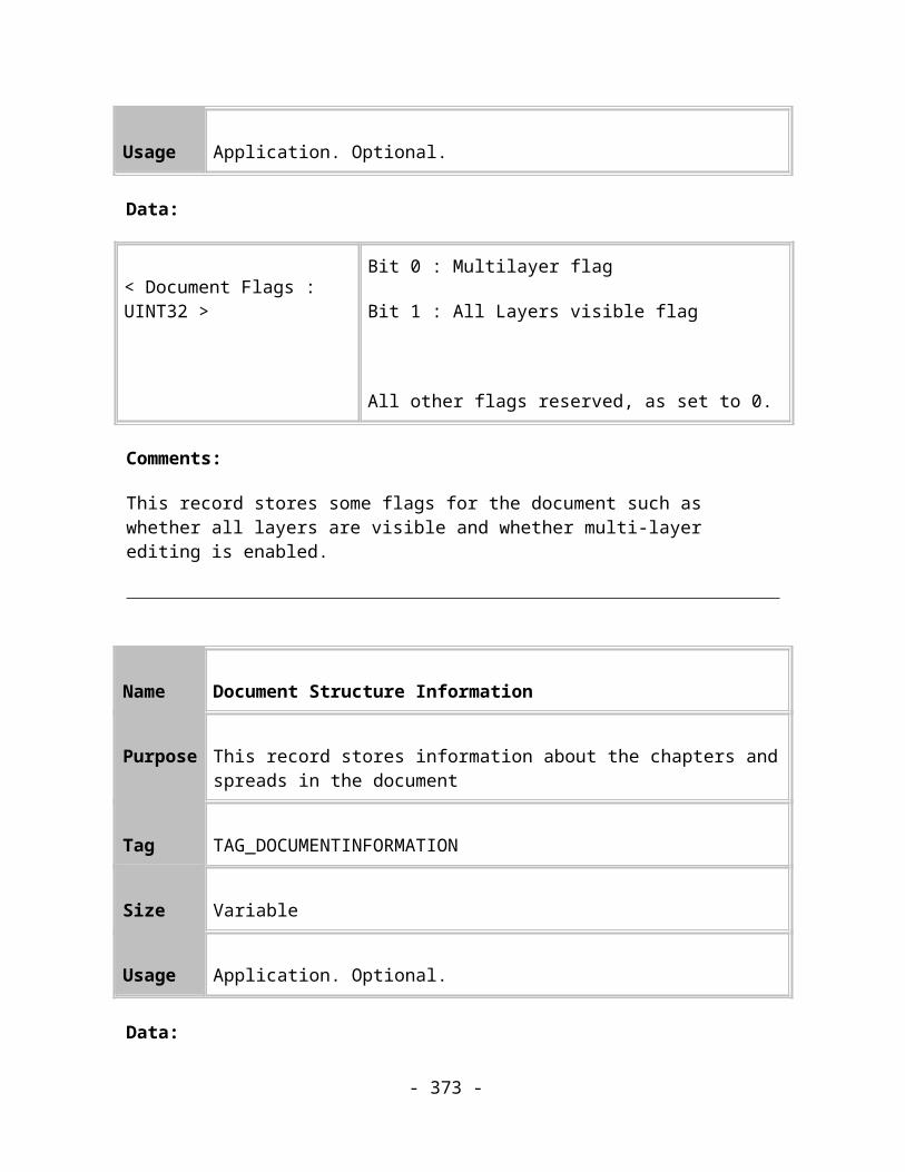
Elements 2
DashDefDashUnit*4
DashUnit*2
REF_DASH_3
Reference Value -3
DashStart 0
LineWidth 72000/4
DashFlags ScaleWithLineWidth
Elements 2
DashDefDashUnit*8
DashUnit*2
REF_DASH_4
Reference Value -4
DashStart 0
LineWidth 72000/4
- 373 -

DashFlags ScaleWithLineWidth
Elements 2
DashDefDashUnit*16
DashUnit*2
REF_DASH_5
Reference Value -5
DashStart 0
LineWidth 72000/4
DashFlags ScaleWithLineWidth
Elements 2
DashDefDashUnit*24
DashUnit*2
REF_DASH_6
Reference Value -6
DashStart 0
- 374 -
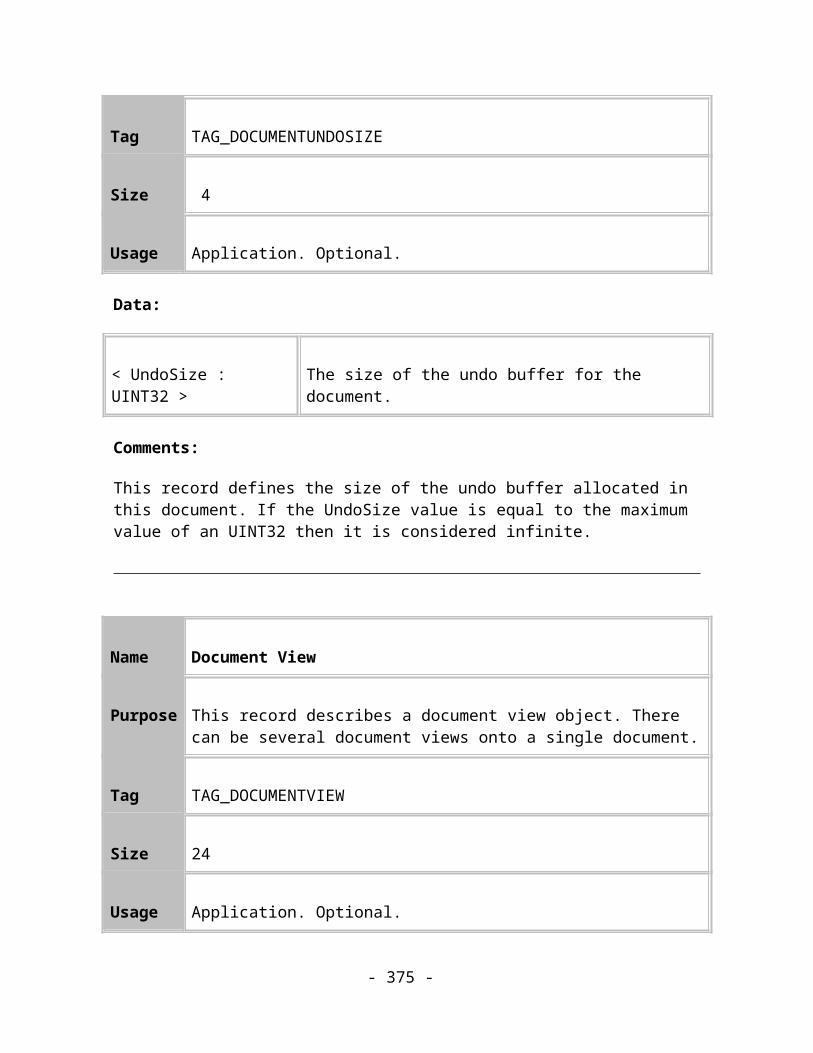
LineWidth 72000/4
DashFlags ScaleWithLineWidth
Elements 2
DashDefDashUnit*4
DashUnit*4
REF_DASH_7
Reference Value -7
DashStart 0
LineWidth 72000/4
DashFlags ScaleWithLineWidth
Elements 2
DashDefDashUnit*8
DashUnit*4
REF_DASH_8
Reference Value -8
- 375 -

DashStart 0
LineWidth 72000/4
DashFlags ScaleWithLineWidth
Elements 2
DashDefDashUnit*16
DashUnit*4
REF_DASH_9
Reference Value -9
DashStart 0
LineWidth 72000/4
DashFlags ScaleWithLineWidth
Elements 2
DashDefDashUnit*8
DashUnit*8
REF_DASH_10
- 376 -

Reference Value -10
DashStart 0
LineWidth 72000/4
DashFlags ScaleWithLineWidth
Elements 2
DashDefDashUnit*16
DashUnit*8
REF_DASH_11
Reference Value -11
DashStart 0
LineWidth 72000/4
DashFlags ScaleWithLineWidth
Elements 4
DashDefDashUnit*4
DashUnit*2
DashUnit*2
- 377 -

DashUnit*2
REF_DASH_12
Reference Value -12
DashStart 0
LineWidth 72000/4
DashFlags ScaleWithLineWidth
Elements 4
DashDefDashUnit*8
DashUnit*2
DashUnit*2
DashUnit*2
REF_DASH_13
Reference Value -13
DashStart 0
LineWidth 72000/4
- 378 -
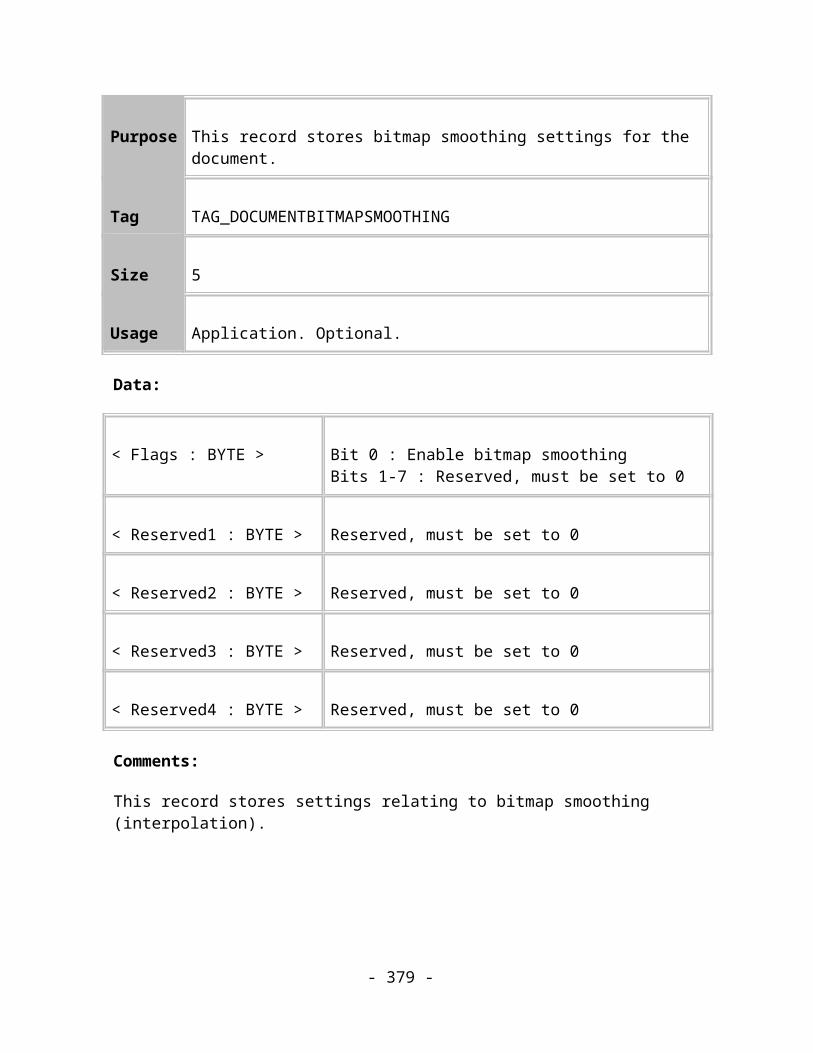
DashFlags ScaleWithLineWidth
Elements 4
DashDefDashUnit*16
DashUnit*2
DashUnit*2
DashUnit*2
REF_DASH_14
Reference Value -14
DashStart 0
LineWidth 72000/4
DashFlags ScaleWithLineWidth
Elements 4
DashDefDashUnit*8
DashUnit*2
DashUnit*4
DashUnit*2
REF_DASH_15
- 379 -

Reference Value -15
DashStart 0
LineWidth 72000/4
DashFlags ScaleWithLineWidth
Elements 4
DashDefDashUnit*16
DashUnit*2
DashUnit*4
DashUnit*2
REF_DASH_16
Reference Value -16
DashStart 0
LineWidth 72000/4
DashFlags ScaleWithLineWidth
Elements 6
DashDefDashUnit*8
- 380 -

DashUnit*2
DashUnit*2
DashUnit*2
DashUnit*2
DashUnit*2
REF_DASH_17
Reference Value -17
DashStart 0
LineWidth 72000/4
DashFlags ScaleWithLineWidth
Elements 6
DashDefDashUnit*16
DashUnit*2
DashUnit*2
DashUnit*2
DashUnit*2
DashUnit*2
- 381 -

REF_DASH_18
Reference Value -18
DashStart 0
LineWidth 72000/4
DashFlags ScaleWithLineWidth
Elements 8
DashDefDashUnit*8
DashUnit*2
DashUnit*2
DashUnit*2
DashUnit*2
DashUnit*2
DashUnit*2
DashUnit*2
REF_DASH_19
Reference Value -19
DashStart 0
- 382 -
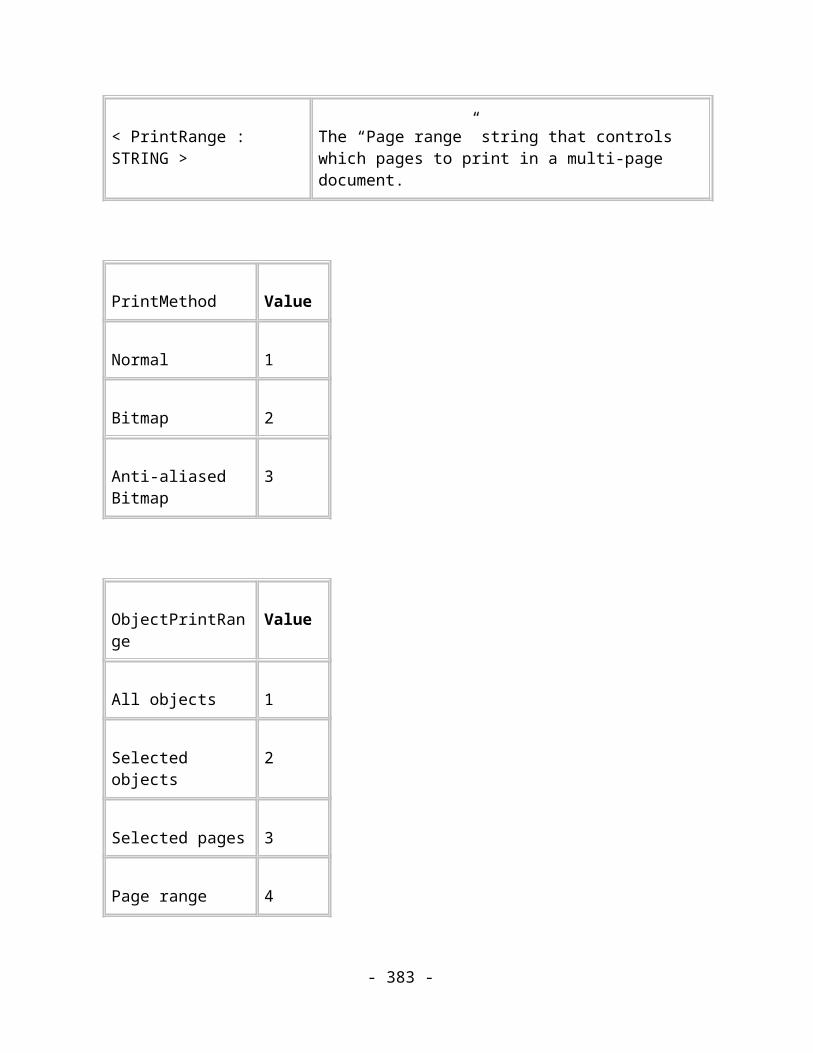
LineWidth 72000/4
DashFlags ScaleWithLineWidth
Elements 8
DashDefDashUnit*16
DashUnit*2
DashUnit*2
DashUnit*2
DashUnit*2
DashUnit*2
DashUnit*2
DashUnit*2
REF_DASH_20
Reference Value -20
DashStart 0
LineWidth 72000/4
DashFlags ScaleWithLineWidth
Elements 8
- 383 -

DashDefDashUnit*8
DashUnit*2
DashUnit*2
DashUnit*2
DashUnit*4
DashUnit*2
DashUnit*2
DashUnit*2
REF_DASH_GUIDELAYER
Reference Value -22
DashStart 0
LineWidth 72000/4
DashFlags
Elements 2
DashDefDashUnit*2
DashUnit*2
This is the dash pattern used to render objects in guide layers with. It's different from the others in that the dashes aren't scaled relative to the line width.
- 384 -

Default colours
The following colours are defined as default colours in v1 of the format, i.e. records don't need to refer to a colour definition record earlier in the file to use one of these colours:
REF_DEFAULTCOLOUR_NONE (-1) no colour
REF_DEFAULTCOLOUR_BLACK (-2) Full black
REF_DEFAULTCOLOUR_WHITE (-3) Full white
REF_DEFAULTCOLOUR_RED (-4) Full red in RGB model
REF_DEFAULTCOLOUR_GREEN (-5) Full green in RGB model
REF_DEFAULTCOLOUR_BLUE (-6) Full blue in RGB model
REF_DEFAULTCOLOUR_CYAN (-7) Full cyan in CMYK model
REF_DEFAULTCOLOUR_MAGENTA (-8)
Full magenta in CMYK model
REF_DEFAULTCOLOUR_YELLOW (-9)
Full yellow in CMYK model
Default Units
The following units are considered defined by default:
Millimetres
- 385 -

Unit reference REF_UNIT_MILLIMETRES (-2)
Unit name Millimetres
Unit abbreviation mm
Size in millipoints 2834.652715
Base unit reference 0 (No base unit)
Numerator 0
Denominator 0
Centimetres
Unit reference REF_UNIT_CENTIMETRES (-3)
Unit name Centimetres
Unit abbreviation cm
Size in millipoints 0 (Based on)
Base unit reference REF_UNIT_MILLIMETRES
Numerator 10.0
- 386 -
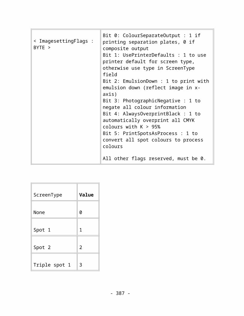
Denominator 1.0
Metres
Unit reference REF_UNIT_METRES (-4)
Unit name Metres
Unit abbreviation m
Size in millipoints 0 (Based on)
Base unit reference REF_UNIT_CENTIMETRES
Numerator 100.0
Denominator 1.0
Kilometres
Unit reference REF_UNIT_KILOMETRES (-5)
Unit name Kilometres
Unit abbreviation km
Size in millipoints 0 (Based on)
- 387 -
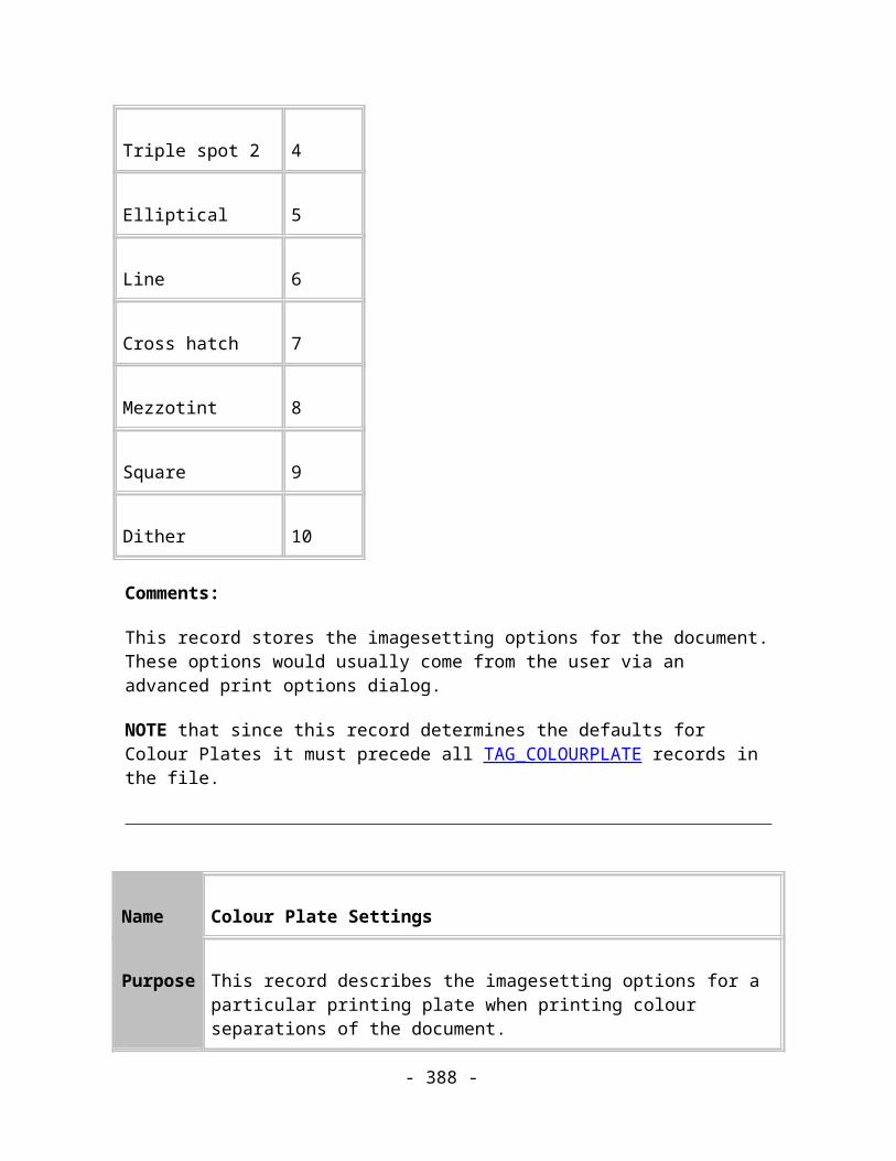
Base unit reference REF_UNIT_METRES
Numerator 1000.0
Denominator 1.0
Millipoints
Unit reference REF_UNIT_MILLIPOINTS (-6)
Unit name Millipoints
Unit abbreviation mp
Size in millipoints 1.0
Base unit reference 0 (No base unit)
Numerator 0.0
Denominator 0.0
Points
Unit reference REF_UNIT_COMP_POINTS (-8)
Unit name Points
- 388 -

Unit abbreviation pt
Size in millipoints 0 (Based on)
Base unit reference REF_UNIT_MILLIPOINTS
Numerator 1000.0
Denominator 1.0
Picas
Unit reference REF_UNIT_PICAS (-8)
Unit name Picas
Unit abbreviation pi
Size in millipoints 0 (Based on)
Base unit reference REF_UNIT_COMP_POINTS
Numerator 12.0
Denominator 1.0
Inches
- 389 -
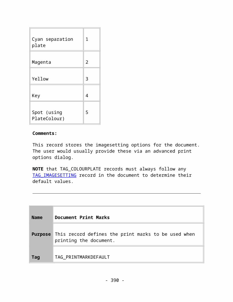
Unit reference REF_UNIT_INCHES (-9)
Unit name Inches
Unit abbreviation In
Size in millipoints 0 (Based on)
Base unit reference REF_UNIT_PICAS
Numerator 6.0
Denominator 1.0
Feet
Unit reference REF_UNIT_FEET (-10)
Unit name Feet
Unit abbreviation Ft
Size in millipoints 0 (Based on)
Base unit reference REF_UNIT_INCHES
Numerator 12.0
- 390 -

Denominator 1.0
Yards
Unit reference REF_UNIT_YARDS (-11)
Unit name Yards
Unit abbreviation Yd
Size in millipoints 0 (Based on)
Base unit reference REF_UNIT_FEET
Numerator 3.0
Denominator 1.0
Miles
Unit reference REF_UNIT_MILES (-12)
Unit name Miles
Unit abbreviation mi
Size in millipoints 0 (Based on)
- 391 -
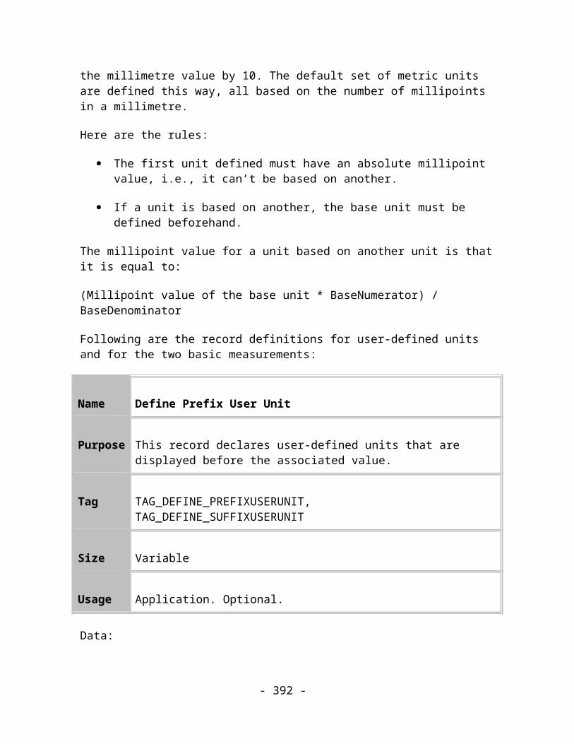
Base unit reference REF_UNIT_YARDS
Numerator 1760.0
Denominator 1.0
Pixels
Unit reference REF_UNIT_PIXELS (-13)
Unit name Pixels
Unit abbreviation pix
Size in millipoints 750
Base unit reference 0 (No base unit)
Numerator 0.0
Denominator 0.0
The default page units are REF_UNIT_CENTIMETRES.
The default font units are REF_UNIT_COMP_POINTS
- 392 -

Default Print Marks
Print Mark 0
Mark Type Registration
Orientation Horizontal
Positions 2MC+4MC+6MC+8MC+10MC+12MC+14MC+16MC
Name Information Marks
Print Mark 1
Mark Type Registration
Orientation Horizontal
Positions 2MC+4MC+6MC+8MC+10MC+12MC+14MC+16MC
Name Crop Marks
Print Mark 2
Mark Type Registration
- 393 -
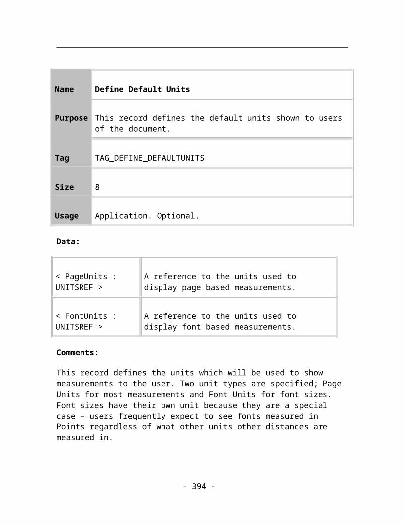
Orientation None
Positions 2MC+4MC+6MC+8MC+10MC+12MC+14MC+16MC
Name Registration targets
Print Mark 3
Mark Type Star
Orientation None
Positions 1MC + 9MC
Name Registration stars
Print Mark 4
Mark Type GreyBar
Orientation Vertical
Positions 15MC
Name Greyscale bar
- 394 -

Print Mark 5
Mark Type Colour Bar
Orientation Vertical
Positions 7MC
Name Progressive Colour Bar
Print Mark 6
Mark Type Colour Bar
Orientation Vertical
Positions 11MC
Name Overprinted Colour Bar
Print Mark 7
Mark Type Registration
- 395 -

Orientation Horizontal
Positions 2MC+4MC+6MC+8MC+10MC+12MC+14MC+16MC
Name Long registration targets
Positions ::= <Region + 1><Format First Letter>+ [+ <Positions>]*
Mark Type Value
Unknown 0
Star 1
Registration 2
ColourBar 3
GreyBar 4
Information 5
Crop 6
Orientation Value
None 0
- 396 -

Vertical 1
Horizontal 2
A Region is an area on the page, outside the normal document area.
Region Value
TopLeft 0
Top1 1
Top2 2
Top3 3
TopRight 4
Right1 5
Right2 6
Right3 7
BottomRight 8
Bottom3 9
Bottom2 10
- 397 -

Bottom1 11
BottomLeft 12
Left1 13
Left2 14
Left3 15
The Format refers to the position of the print mark within its region.
Format Value
Left 0x01
Centre 0x02
Right 0x04
Top 0x08
Middle 0x10
Bottom 0x20
- 398 -

Glossary
Application Record A record that contains information applicable to all documents.
Bitmap graphic An image defined by an array of pixels. Frequently bigger than a vector graphic but is more suited to photographic images. Can suffer from loss of visible quality when transformed or when displayed on hardware whose colour depth or resolution differ from the bitmap.
Chapter An optional grouping of Spreads.
Closed path A Path with its end-point the same as its start-point. c.f. open path.
CorelXARA An Illustration program developed by Xara Group Ltd. which can read and write Xar files.
Deprecated Said of a program or feature that is considered obsolescent and in the process of being phased out, usually in favour of a specified replacement.
Dictionary A cache of Sequence numbers used to maintain references to records.
Document An optional grouping of Chapters. The root of a subtree whose children are Chapters.
Often synonymous with 'File' because it's very common for a file to contain just one Document.
Extension Record A record that provides information to readers so that they can correctly handle unknown records.
FileA stream of bytes.
Often synonymous with "Document".
- 399 -

File identifier A unique set of bytes at the start of the file which identify this file as a Xar file.
Framework Record A record that doesn't have any direct effect on the image being described.
GIF 'Graphics Interchange Format', a standard lossless bitmap file format.
Group A simple item grouping of number of objects and attributes together.
Image Record A record that has some direct effect on the image being described.
JPEG 'Joint Photographic Experts Group', a standard 'lossy' bitmap file format - particularly suited to representing photographic images.
Layer A grouping of objects and attributes which controls the visibility and editability of all the objects on the Layer.
Library A logical grouping of a set of objects e.g. colours and bitmaps.
Navigation Record One of two records, 'Up' and 'Down', that create a tree structure within the Xar file.
ObjectA record that defines a renderable entity - something that will be visible to the user.
Sometimes used in a looser sense as a synonym for Record. This usage comes from the implementation of Xar Records as objects in an object oriented language such as C++.
Open path A path with its end points at different locations. c.f. closed path.
- 400 -

Panose A TrueType font matching system.
Path A sequence of coordinates that describe a line. It can contain straight and curved sections and be open or closed.
PNG "Portable Network Graphic", a new lossless bitmap file format.
Reader A program that converts the raw bytes of a Xar file into a usable graphical description and often goes on to render that description.
Record The elements which make up the data in the Xar file format. Each record has a standard header consisting of a unique Tag and a Size field. Following the header is an optional data section.
Sequence number A number unique to each record in the file, starting at one for the first and increasing by one for each subsequent record in the record stream.
Spread An optional grouping of optional pages and Layers.
Subtree A tree that is inside another tree.
Tag A unique identifier for each record - labels the record 'type' or 'class'.
TIFF 'Tagged Image File Format', a standard encompassing may different ways of storing bitmaps.
Tree An arrangement of data items (Records) which places each data item in a list of similar items (siblings) which all share a common 'root' data item. Each data item can itself be the root of a tree.
URL 'Uniform Resource Locator' addresses a resource on the
- 401 -

Internet. Typically addresses pages on the World Wide Web.
Vector graphic An image defined in terms of the lines, or 'vectors', that describe it. Can be more compact than a bitmap. Can be transformed without loss of quality.
Writer A program that converts a graphic into the raw bytes of a Xar file.
- 402 -