dosimetric considerations for patients with hip … · dosimetric considerations for patients with...
TRANSCRIPT
Dosimetric considerations for patients with HIP prostheses undergoingpelvic irradiation. Report of the AAPM Radiation Therapy CommitteeTask Group 63
Chester ReftUniversity of Chicago, Chicago, Illinois 60637
Rodica AlecuU.S. Oncology, Texas Cancer Center, Sherman, Texas
Indra J. DasUniversity of Pennsylvania, Philadelphia, Pennsylvania
Bruce J. GerbiUniversity of Minnesota Medical School, Minneapolis, Minnesota
Paul KeallVirginia Commonwealth University, Richmond, Virginia
Eugene LiefNew York University Medical Center, New York
Ben J. MijnheerNetherlands Cancer Institute, Amsterdam, Netherlands
Nikos PapanikolaouUniversity of Arkansas Medical Sciences
Claudio SibataEast Carolina University School of Medicine, Greenville, North Carolina
Jake Van DykLondon Regional Cancer Centre, Ontario, Canada
~Received 25 July 2002; accepted for publication 10 February 2003; published 30 May 2003!
This document is the report of a task group of the Radiation Therapy Committee of the AAPM andhas been prepared primarily to advise hospital physicists involved in external beam treatment ofpatients with pelvic malignancies who have high atomic number~Z! hip prostheses. The purpose ofthe report is to make the radiation oncology community aware of the problems arising from thepresence of these devices in the radiation beam, to quantify the dose perturbations they cause, and,finally, to provide recommendations for treatment planning and delivery. Some of the data andrecommendations are also applicable to patients having implanted high-Z prosthetic devices such aspins, humeral head replacements. The scientific understanding and methodology of clinical dosim-etry for these situations is still incomplete. This report is intended to reflect the current state ofscientific understanding and technical methodology in clinical dosimetry for radiation oncologypatients with high-Z hip prostheses. ©2003 American Association of Physicists in Medicine.@DOI: 10.1118/1.1565113#
Key words: hip prosthesis, dose perturbation
TABLE OF CONTENTS
I. INTRODUCTION. . . . . . . . . . . . . . . . . . . . . . . . . . . . 1163II. RADIATION PHYSICS CONSIDERATIONS. . . . 1163III. HIP PROSTHESES—GENERAL
PROPERTIES. . . . . . . . . . . . . . . . . . . . . . . . . . . . . . 1166IV. QUANTIFICATION OF THE
PERTURBATIONS PRODUCED BYPROSTHETIC DEVICES IN THE ABSORBEDDOSE DISTRIBUTION. . . . . . . . . . . . . . . . . . . . . . 1167
A. Beam attenuation—measurements. . . . . . . . . . . . 1168
B. Treatment planning and manual dosecalculation aspects. . . . . . . . . . . . . . . . . . . . . . . . 11691. Beam attenuation. . . . . . . . . . . . . . . . . . . . . . 11692. Current TPS limitations and future
possibilities. . . . . . . . . . . . . . . . . . . . . . . . . . . 11723. Neutron production. . . . . . . . . . . . . . . . . . . . . 1174
C. In vivo measurements. . . . . . . . . . . . . . . . . . . . . . 1174V. POSSIBLE ACTIONS FOR MINIMIZING THE
DOSE PERTURBATIONS. . . . . . . . . . . . . . . . . . . . 1175A. Special beam arrangements. . . . . . . . . . . . . . . . . 1176B. Dose compensation. . . . . . . . . . . . . . . . . . . . . . . . 1177
VI. RECOMMENDATIONS. . . . . . . . . . . . . . . . . . . . . 1178
1162 1162Med. Phys. 30 „6…, June 2003 0094-2405 Õ2003Õ30„6…Õ1162Õ21Õ$20.00 © 2003 Am. Assoc. Phys. Med.

I. INTRODUCTION
The success or failure of radiation therapy treatments de-pends upon the accuracy with which the dose prescription isfulfilled. For many diseases, the outcome of the treatmentdepends upon the dose being delivered to an accuracy of63%–4%~one standard deviation!.1,2 This is a stringent re-quirement for routine treatments and is difficult to achieve ifall sources of treatment uncertainty are evaluated. Most ofthe national and international guidelines3–7 for consistencyand accuracy in radiation dosimetry provide information forhomogeneous media, but the human body consists of manycomponents that deviate significantly from unit density, e.g.,bone, lung, teeth, air cavities, and small intercalated spaceswithin bone. In addition to these naturally occurring internalinhomogeneities, man-made materials may also be presentsuch as mandibular plates for reconstruction, hip, leg, andarm prostheses, spinal cord fixation devices, surgical rods,stents, and various dental fillings. In this report we focus onhip prostheses. These devices are usually made from highatomic number~high-Z! elements. In this study high-Z isdefined as a material with atomic number greater than corti-cal bone. In megavoltage photon beams these materials havethe potential to greatly affect the dose delivered to the pre-scription point and to tissue shielded by the prosthesis. Con-sequently, dramatic differences in the treatment outcomefrom what was originally intended can result.
As the population ages and the use of hip prostheses be-come more common, the problem of treating these patientswill also increase. Although at this time there are few datashowing a decrease in tumor control due to the reduced tar-get dose from shadowing of the prosthesis, or an increase inthe complication rates due to the dose perturbation by thepresence of metallic implants, problems could arise in thefuture. In groin irradiation for gynecological malignanciesusing opposed anterior/posterior fields, Grigsbyet al.8 re-ported hip fractures in patients at doses greater than 50 Gy.But, to the best knowledge of this group, no quantitative dataare available on the effects of the increased dose at the in-terface between a hip prosthesis and surrounding tissue inpatients undergoing radical treatment of tumors in the pelvicregion. However, if dose escalation continues in treating pel-vic tumors, the decreased tumor dose and the increased dosenear the bone-metal interface could become factors in tumorcontrol and radiation complications such as bone necrosisand weakening of the fixation of the implant.
A survey of 30 institutions conducted by this task groupshowed that the number of patients with prosthetic devices,which could affect their radiation therapy, was 1%–4% ofthe total number of patients. No general consensus on how tomanage the treatment of these cases was observed. Someinstitutions ignore the presence of the device altogether.Other institutions modify the beam orientation to avoid thedevice even if the result is to give additional dose to criticalstructures adjacent to the planning target volume. Sometimestreating through sensitive structures is an appropriate solu-tion to the problem if the total prescribed dose is low enoughso that the resultant dose to the structure is below the toler-
ance dose. Some institutions try to account for the presenceof the device by using computer treatment planning pro-grams or hand calculations involving a correction for theattenuation of the device. Others may fabricate compensatorsto correct the dose distribution in the target while some mayuse a combination of these approaches. The increasing avail-ability of intensity modulated radiation therapy may offer amethod for treating these patients. All the survey respondentsacknowledged that high-Z devices constitute a problem withthe patient’s treatment and that recommendations for dealingwith these situations would be useful. In response to theseconcerns, this task group was formed to identify the prob-lems caused by the presence of high-Z hip prostheses in pel-vic megavoltage photon radiation treatments. Practical sug-gestions are given for dealing with the presence of prosthesesand to minimize, or at least quantify, their undesired effects,while reducing the impact to the surrounding critical struc-tures.
II. RADIATION PHYSICS CONSIDERATIONS
The presence of a high-Z inhomogeneity in an irradiatedwater phantom or patient results in attenuation of the radia-tion through the inhomogeneity as well as local perturbationsknown as interface effects. There are numerous reports9–30
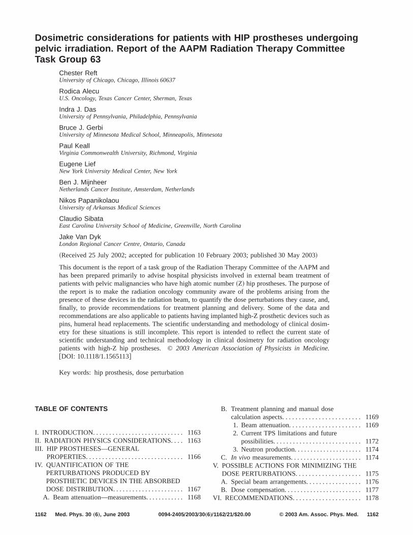
on attenuation effects in non-tissue-equivalent materials. Fig-ure 1 illustrates the perturbations to the central axis depthdose curve for 6 and 18 MV broad radiation beams incidenton a water phantom containing an infinitely wide 3 cm Co–Cr–Mo slab from depths 5 to 8 cm. Three dose regions areshown in the figure. Region 1 is a distance greater thandmax
from the implant, and regions 2 and 3 are at the proximal anddistal ends of the implant, respectively. The central axisdepth doses in region 1 shown in Figs. 1~a! and 1~b! are at adistance greater thandmax from the inhomogeneity, and illus-trate the effects of absorption and scatter by the implant. Thebeam attenuation in the material is somewhat offset by thein-scatter from the unobstructed portion of the beam. For asmaller beam that just encompasses the implant, the curvewould run parallel to the unattenuated curve since therewould be a smaller contribution from in-scatter by the unob-structed portion of the beam. However, since treatment fieldsfor the pelvis are generally larger than the inhomogeneity,in-scatter from the unobstructed portion of the beam partiallycompensates for the loss of dose due to attenuation distal tothe inhomogeneity. The magnitude and the spatial extent ofthese effects depend on the energy of the radiation as well asthe density, atomic number, and dimensions of the inhomo-geneity. For photon beams above 10 MV, there are gamma-rays produced by interactions of contaminant neutrons withthe high-Z material. These are not included in the MonteCarlo simulation, but will be shown~Sec. IV B 3! to contrib-ute little dose to tissue around a prosthesis.
The decrease in intensity of the radiation at distancesgreater than the secondary electron range downstream fromthe inhomogeneity can be calculated with knowledge of thedensity and atomic number of the material and its linear ormass attenuation coefficients~m andm/r, respectively!. The
1163 Reft et al. : Task Group 63 Report 1163
Medical Physics, Vol. 30, No. 6, June 2003
primary fluence beyond the metallic implant is approxi-mately given by
c5c0e2mt, ~1!
wherec is the photon fluence after passing through a thick-nesst of high-Z material,c0 is the initial fluence, andm isthe total composite linear attenuation coefficient includingthe various interactions: photoelectric~t!, Compton~s!, andpair production~k! averaged over the photon spectrum:
m5t1s1k. ~2!
It is more difficult to account for the contribution of scatteredphotons and the effects of electron disequilibrium. Approxi-
mate methods~e.g., effective TMR ratios to partially accountfor scatter! are described in Sec. IV B 1. The problems asso-ciated with the interface effect are much more complex, butprobably less clinically important within the context of hipprosthesis. Various researchers in their publications describequantitatively the dose perturbation that occurs at the high-Zinterface.13,31–56At the interface between bone and prosthe-sis, the dose perturbation is similar to that at a tissue/high-Zinterface, albeit the magnitude and extent of the effects willbe diminished due to a closer match between the atomicnumbers of the two materials. Perturbations in the dose dis-tributions in regions 2 and 3~Fig. 1! occur near the interface
FIG. 1. Dose perturbation near and farfrom a Co–Cr–Mo inhomogeneity.~a!and ~b! show the perturbation to thecentral axis percentage depth dose for6 and 18 M beams incident on a 3 cmthick Co–Cr–Mo slab inhomogeneity.Region 1 is greater thandmax from theimplant and zones 2 and 3 are at theproximal and distal ends of the im-plant, respectively.
1164 Reft et al. : Task Group 63 Report 1164
Medical Physics, Vol. 30, No. 6, June 2003

and extend a distance approximatelydmax from it. On bothsides of a high-Z material within the homogeneous medium,there are rapid changes in dose due to electron transport,which extends into each medium over a distance of the orderof the range of the secondary electrons. These effects areillustrated in Figs. 1~a! and 1~b! for 6 and 18 MV beams,respectively. This dose may be higher or lower than that atthe same geometric depth in a homogeneous medium. Thedose perturbation depends upon the incident photon energy,differences in the photon energy transfer coefficients, theatomic number~Z!, the mass density and thickness of theinhomogeneity, and the differences in multiple scatter of thesecondary electrons. For energies greater than 10 MV theremay be an increased dose distal to the high-Z material that isattributed to pair-production interactions in the metal. Lateralto the inhomogeneity, the electron fluence increases due tothe increased lateral scattering from the material producingan increased dose to the surrounding tissue. A dose correc-tion factor ~CF! can be defined as the ratio of doses with(Di) and without (Dh) the presence of the interface as
CF~E,A,Ap ,d,t,x,Z,r,u!5Di /Dh , ~3!
whereE is the beam energy,A is the field size,Ap is the areaof the prosthesis from the beam’s perspective,d is the depthof the interface from the surface,t is the thickness of thehigh-Z medium creating the interface with the soft tissue~low-Z!, x is the distance either proximal or distal from theinterface to the point where the dose is estimated, Z andr arethe atomic number and physical density of the inhomogene-ity, respectively,u is the beam angle relative to the implant,Di is the dose in the presence of the interface, andDh is thedose in a homogeneous medium. Although there are verylimited data on the interface effect and beam angle, Nadrow-itz and Feyerabend57 reported it to be an important param-eter. However, for a cylindrical prosthetic geometry,u can beignored in the equation. Furthermore, the CF can be sepa-rated into two components: the backscattered dose perturba-tion factor~BSDF31! at the entrance side of the high-Z inho-mogeneity, and the forward dose perturbation factor~FDPF43,44! on the exit side of the inhomogeneity. The mag-nitude and the extent of the above effects are shown inTables I and II for a slab inhomogeneity~bone, steel and
lead! for 6 and 18 MV photon beams58 in a water-equivalentphantom. Except in the build-up region, the correction fac-tors are independent of the depth of the high-Z material. Forthe given material thickness the FDPF behaves significantlydifferent with energy than the BSDF. At the interface for 6MV it varies from 0.94 to 0.84 for bone and lead, and for 18MV, it varies from 1.05 to 1.41 for bone and lead, respec-tively. The magnitude of BSDF is between 1.08 and 1.70 forbone and lead, respectively, and falls off rapidly from theinterface. Although we are unaware of published data forcorrection factors at a bone/high-Z interface, we expect theeffect to be smaller than that at a tissue/high-Z interface byapproximately the ratio of their atomic numbers. Ding andYu9 using Monte Carlo simulations investigated the interfaceeffects for parallel-opposed photon beams.
Gullane56 measured doses at interfaces using a wall-lessionization chamber. Figures 2~a!–2~d! show results for stain-less steel and titanium for both single and parallel-opposedbeams. The interface doses increase by as much as 50% atthe proximal surface of the metallic inhomogeneity.
Erlanson et al.,18 using small Si diodes, measured thedose increase at the distal site behind a titanium alloy pros-thesis in a water phantom for photon energies of 6, 20, and50 MV. They concluded that for radiation therapy in the pel-vic region using a four-field box technique, the mean doseclose to the prosthesis is below the prescription dose of 65Gy and below the critical level of complications, i.e., even a25% increase in dose over that for a normal hip in a smallvolume near the prosthesis is not expected to result in anincrease in morbidity. However, escalation of the prescrip-tion dose and the enhanced dose at the bone–prosthesis in-terface could increase the probability for bone necrosis. Thenormal tissue complication probability doses for bone necro-sis are estimated to be 52 and 65 Gy for the complicationprobabilities of 5% in 5 years~TD 5/5! and 50% in 5 years~TD 50/5!, respectively.59,60 There are on-going dose escala-tion studies for treating the prostate. The Radiation TherapyOncology Group~RTOG! closed a protocol~94-06! in whichthe prescribed dose was 78 Gy. Some institutions treat high-risk prostate patients to 86.4 Gy by using field arrangementsthat avoid the prosthesis. Depending upon the field arrange-
TABLE I. BSDF versus distance from interface for 10310 cm2 whereBSDF5Di /Dh andDi andDh are the doses with and without the presenceof the interface, respectively.
Material Bone LeadDensity ~g/cm3! 1.83 11.4
Atomic no. 13 82
Distance~cm! 6 MV 18 MV 6 MV 18 MV0.1 1.03 1.04 1.34 1.450.2 1.01 1.02 1.20 1.300.4 1.01 1.01 1.01 1.141.0 1.00 1.00 1.00 1.061.4 1.00 1.00 1.00 1.03
TABLE II. FDPF versus distance from the interface for 10310 cm2 whereFDPF5Di /Dh andDi andDh are the doses with and without the presenceof the interface, respectively.
Material Bone Steel LeadDensity ~g/cm3! 1.83 7.76 11.4
Thickness~g/cm3! 1.83 2.56 2.28Atomic no. 13 26 82
Distance~cm!
6MV
18MV
6MV
18MV
6MV
18MV
0.05 0.94 1.05 0.85 1.20 0.84 1.410.1 0.95 0.04 0.87 1.19 0.85 1.400.5 0.98 1.03 0.92 1.15 0.88 1.291.0 0.99 1.02 0.94 1.11 0.91 1.212.0 0.99 1.01 0.95 1.05 0.93 1.104.0 0.99 1.00 0.94 0.98 0.93 0.986.0 0.99 0.99 0.94 0.96 0.93 0.94
1165 Reft et al. : Task Group 63 Report 1165
Medical Physics, Vol. 30, No. 6, June 2003

ments and the beam energy, there is the potential for an en-hanced dose near the prosthesis–bone interface that couldpotentially increase the incidence of bone necrosis. Most cur-rent treatment planning systems account for beam attenua-tion, if the composition of the inhomogeneity is known, andthe CT number to electron density conversion curve is suit-able. However, only Monte Carlo based treatment planningsystems promise the ability to calculate the dose accuratelynear a high-Z inhomogeneity.
III. HIP PROSTHESES—GENERAL PROPERTIES
There are many designs of hip prostheses@see Fig. 3~a!#.Usually, a total hip replacement will include a prosthetic ac-etabular cup and a femoral component. The acetabular cupconsists of a polyethylene core supported by either a Co–Cr–Mo or Ti alloy outer shell. The femoral component con-sists of a stem and a head, which can be hollow or solid,made of Co–Cr–Mo, Ti alloy, or steel. Some patients mighthave all three components, while others might have only thefemoral stem implanted. The physical properties that are im-portant dosimetrically are hollowness, shape, size, and com-position. The majority of the current hip prosthetic devicesare made of Co–Cr–Mo alloys. Stainless steel was used inthe past, and may still be found in patients with older im-plants. Titanium is also used in some cases.
A thorough study on the influence of hip prostheses on thedose distribution was reported by Sibataet al.12 for incident6 and 18 MV photon fields. In this study, prosthetic devicesfrom several manufacturers were used. Table III~a!, from Si-bata et al.,12 gives the common composition of the alloysused in the manufacture of the hip prosthesis devices and thecalculated electron densities of the alloys relative to water.The physical properties, such as mass density, mass attenua-tion coefficient, effective atomic number, electron density,and relative electron density for the three most commontypes of hip prosthesis are provided in Table III~b! fromHazukaet al.14 A difference as high as 17%–19% is shownbetween the physical density and the relative electron densityof each alloy, the difference being much larger than the onecalculated for biologically equivalent materials.14 The rela-tive electron densities of similar types of prosthetic devicesare slightly different in the two sets of data presented inTables III~a! and ~b!.
Besides the use of metals for prosthetic materials, ceramicand synthetic materials are occasionally used as implants forsurgery. Ball heads of densely sintered, high-purity alumina(Al2O3) ceramic and polyethylene have been used for pros-thetic parts. The mass density and relative electron densitywith respect to water for alumina are 3.97 g/cm3 and 3.52,respectively. The dosimetric problems with these prosthesesare expected to be smaller than those reported here on me-tallic prostheses because its electron density and effectiveatomic number~;16! are lower.
The effect of the radiation on the prosthetic materials isnot of concern because published data61 indicate that dosesof the order of MGy are required to affect the mechanicalproperties of these materials.
FIG. 2. High Z-tissue-metal interface effects for 15315 cm2 field. The dataare normalized to 1.00 at a distance from the interface greater than the rangeof the electrons set in motion.~a! Dose perturbations due to a stainless steelplate for a single 18 MV unidirectional beam.~b! Dose perturbations due toa stainless steel plate for parallel-opposed 18 MV beams.~c! Relative dosein tissue on both sides of a Ti or steel plate irradiated by parallel-opposed 6MV beams.~d! Relative dose in acrylic on one side of Ti irradiated byparallel-opposed60Co, 6 MV and 18 MV beams~Ref. 56!.
1166 Reft et al. : Task Group 63 Report 1166
Medical Physics, Vol. 30, No. 6, June 2003

IV. QUANTIFICATION OF THE PERTURBATIONSPRODUCED BY PROSTHETIC DEVICES INTHE ABSORBED DOSE DISTRIBUTION
As previously mentioned, when a radiation beam passesthrough a prosthesis, perturbations of the absorbed dose dis-tribution occur due to the increased attenuation of the beamby the prosthesis and interactions at the bone–metal inter-face. Several groups11,12,14–17 have attempted to quantify
these perturbations by measuring the dose—either in phan-toms containing a prosthesis or in patients—or by calculatingwith a treatment planning system~TPS!. Most prosthetic de-vices are made of Co–Cr–Mo or titanium alloy, so some ofthe measurement data in this report may also be useful forimplants other than hip prostheses. However, one should becautious in using these data for other type of implants be-cause the size, shape, and composition of the device will
FIG. 3. ~a! Prosthesis models and cross sections of the models.~b! Measured~2! versus calculated~m! dose behind a titanium prosthesis at depths of 10, 15,and 20 cm for 6 and 18 MV beams~Ref. 12!. Field size 10315 cm2, 100 cm SSD and the prosthesis is at a depth of 6.5 cm~reprinted from Ref. 12!.
1167 Reft et al. : Task Group 63 Report 1167
Medical Physics, Vol. 30, No. 6, June 2003

strongly affect the dose perturbation. The measured magni-tude of these effects is presented in this section for the threemost common type hip prosthesis: Co–Cr–Mo, Ti, and steel.
A. Beam attenuation—measurements
Hazukaet al.14 published data on the transmission factorthrough hip prosthesis devices made of Co–Cr–Mo, Ti, andsteel for 4 and 10 MV photon beams. The transmission wasmeasured in a water phantom with 0.1 cm3 sealed ion cham-bers and with the beam positioned with its central axis pass-ing through the approximate center of the solid stem of eachprosthesis. Measured beam profiles were used to correlatebeam transmission with the cross-sectional dimensions ofeach prosthesis. In each case, the prosthesis was positionedat 5 cm depth in water and measurements were made at 10and 15 cm depth for 838 and 15315 cm2 field sizes. Theirmeasurements are summarized in Table IV. The lowest trans-
mission was measured for a Co–Cr–Mo prosthesis~0.657for 4 MV photons!. The transmission increased with fieldsize and energy. The data show that for each prosthesis, at agiven energy and depth, the transmission increases with thefield size, due to the increased phantom scatter which par-tially offsets the shielding effect of the prosthesis. The in-crease in transmission ranged from 2% to 8% for the threeprostheses used in these measurements, when the field sizewas increased from 838 cm2 to 15315 cm2. The cross-sectional dimensions of the three prostheses are different;therefore, the differences in the transmission data cannot beattributed only to the material of the prosthesis. Data forprostheses fabricated from different materials with identicalgeometrical dimensions~28 mm prosthesis head diameter!were published by Sibataet al.,12 for 6 and 18 MV photonbeams. The cross sections of the prosthetic devices used in
TABLE IV. Transmission factors for 4 and 10 MV photon beams~Ref. 14! for the selected prostheses given inTable III~a!.
Photon energy~MV ! 4 10Field size~cm2! 838 15315 838 15315Prosthesis/depth~cm! 10 15 10 15 10 15 10 15Stainless steel 0.763 0.764 0.786 0.795 0.807 0.799 0.816 0.819Co–Cr–Mo 0.657 0.672 0.708 0.714 0.735 0.736 0.748 0.749Ti 0.861 0.855 0.869 0.876 0.887 0.879 0.891 0.894
TABLE III. ~a! Elemental composition of various prosthetic devices~Ref. 12!. ~b! Physical properties of some selected hip prostheses~Hazukaet al., Ref. 14!.
~a!Stainless steel
wroughtCo-Cr-Mo
cast-wroughtTitanium
cast-wrought
~A! Composition of prosthesis alloys~%Weight!ElementCarbon 0.08 max 0.35 max 0.08 maxManganese 2.00 max 1.00 max ¯
Phosphorus 0.03 max ¯ ¯
Sulfur 0.03 max ¯ ¯
Silicon 0.75 max 1.00 max ¯
Oxygen ¯ ¯ 0.13 maxCobalt ¯ Balance~57.4–65! ¯
Chromium 17–20 27–30 ¯
Nickel 10–14 2.50 max ¯
Molybdenum 2–4 5–7 ¯
Iron Balance~59–70! 0.75 max 0.25 maxAluminum ¯ ¯ 5.6–6.5Vanadium ¯ ¯ 3.5–4.5Titanium ¯ ¯ Balance~88.5–91!
~B! Electron density relative to waterRange 6.55–6.61 6.79–6.90 3.72–3.76Average 6.58 6.84 3.74
~b!Prosthesis Cross Sectional
dimension~mm!Thickness3width
Physicaldensity~g/cm3!
Mass attenuationcoefficient at 4MV~cm2/g!
Effectiveatomic
no.
Electrondensity
(e2/cm3)
Relativeelectrondensity
Stainless steel 11.4320.0 8.1 0.047 26.7 2.331024 6.83Co–Cr–Mo 16.2 diameter 7.9 0.044 27.6 2.231024 6.74Titanium 13.6315.0 4.3 0.048 21.4 1.231024 3.6
1168 Reft et al. : Task Group 63 Report 1168
Medical Physics, Vol. 30, No. 6, June 2003
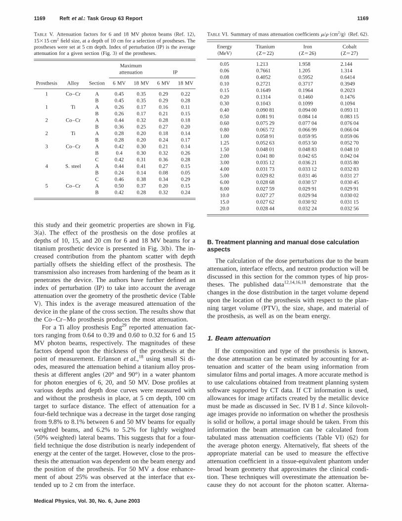
this study and their geometric properties are shown in Fig.3~a!. The effect of the prosthesis on the dose profiles atdepths of 10, 15, and 20 cm for 6 and 18 MV beams for atitanium prosthetic device is presented in Fig. 3~b!. The in-creased contribution from the phantom scatter with depthpartially offsets the shielding effect of the prosthesis. Thetransmission also increases from hardening of the beam as itpenetrates the device. The authors have further defined anindex of perturbation~IP! to take into account the averageattenuation over the geometry of the prosthetic device~TableV!. This index is the average measured attenuation of thedevice in the plane of the cross section. The results show thatthe Co–Cr–Mo prosthesis produces the most attenuation.
For a Ti alloy prosthesis Eng29 reported attenuation fac-tors ranging from 0.64 to 0.39 and 0.60 to 0.32 for 6 and 15MV photon beams, respectively. The magnitudes of thesefactors depend upon the thickness of the prosthesis at thepoint of measurement. Erlansonet al.,18 using small Si di-odes, measured the attenuation behind a titanium alloy pros-thesis at different angles~20° and 90°! in a water phantomfor photon energies of 6, 20, and 50 MV. Dose profiles atvarious depths and depth dose curves were measured withand without the prosthesis in place, at 5 cm depth, 100 cmtarget to surface distance. The effect of attenuation for afour-field technique was a decrease in the target dose rangingfrom 9.8% to 8.1% between 6 and 50 MV beams for equallyweighted beams, and 6.2% to 5.2% for lightly weighted~50% weighted! lateral beams. This suggests that for a four-field technique the dose distribution is nearly independent ofenergy at the center of the target. However, close to the pros-thesis the attenuation was dependent on the beam energy andthe position of the prosthesis. For 50 MV a dose enhance-ment of about 25% was observed at the interface that ex-tended up to 2 cm from the interface.
B. Treatment planning and manual dose calculationaspects
The calculation of the dose perturbations due to the beamattenuation, interface effects, and neutron production will bediscussed in this section for the common types of hip pros-theses. The published data12,14,16,18 demonstrate that thechanges in the dose distribution in the target volume dependupon the location of the prosthesis with respect to the plan-ning target volume~PTV!, the size, shape, and material ofthe prosthesis, as well as on the beam energy.
1. Beam attenuation
If the composition and type of the prosthesis is known,the dose attenuation can be estimated by accounting for at-tenuation and scatter of the beam using information fromsimulator films and portal images. A more accurate method isto use calculations obtained from treatment planning systemsoftware supported by CT data. If CT information is used,allowances for image artifacts created by the metallic devicemust be made as discussed in Sec. IV B 1d. Since kilovolt-age images provide no information on whether the prosthesisis solid or hollow, a portal image should be taken. From thisinformation the beam attenuation can be calculated fromtabulated mass attenuation coefficients~Table VI! ~62! forthe average photon energy. Alternatively, flat sheets of theappropriate material can be used to measure the effectiveattenuation coefficient in a tissue-equivalent phantom underbroad beam geometry that approximates the clinical condi-tion. These techniques will overestimate the attenuation be-cause they do not account for the photon scatter. Alterna-
TABLE V. Attenuation factors for 6 and 18 MV photon beams~Ref. 12!,15315 cm2 field size, at a depth of 10 cm for a selection of prostheses. Theprostheses were set at 5 cm depth. Index of perturbation~IP! is the averageattenuation for a given section~Fig. 3! of the prostheses.
Prosthesis Alloy Section
Maximumattenuation IP
6 MV 18 MV 6 MV 18 MV
1 Co–Cr A 0.45 0.35 0.29 0.22B 0.45 0.35 0.29 0.28
1 Ti A 0.26 0.17 0.16 0.11B 0.26 0.17 0.21 0.15
2 Co–Cr A 0.44 0.32 0.28 0.18B 0.36 0.25 0.27 0.20
2 Ti A 0.28 0.20 0.18 0.14B 0.28 0.20 0.24 0.17
3 Co–Cr A 0.42 0.30 0.21 0.14B 0.4 0.30 0.32 0.26C 0.42 0.31 0.36 0.28
4 S. steel A 0.44 0.41 0.27 0.15B 0.24 0.14 0.08 0.05C 0.46 0.38 0.34 0.29
5 Co–Cr A 0.50 0.37 0.20 0.15B 0.42 0.28 0.32 0.24
TABLE VI. Summary of mass attenuation coefficientsm/r ~cm2/g! ~Ref. 62!.
Energy~MeV!
Titanium(Z522)
Iron(Z526)
Cobalt(Z527)
0.05 1.213 1.958 2.1440.06 0.7661 1.205 1.3140.08 0.4052 0.5952 0.64140.10 0.2721 0.3717 0.39490.15 0.1649 0.1964 0.20230.20 0.1314 0.1460 0.14760.30 0.1043 0.1099 0.10940.40 0.090 81 0.094 00 0.093 110.50 0.081 91 0.084 14 0.083 150.60 0.075 29 0.077 04 0.076 040.80 0.065 72 0.066 99 0.066 041.00 0.058 91 0.059 95 0.059 061.25 0.052 63 0.053 50 0.052 701.50 0.048 01 0.048 83 0.048 102.00 0.041 80 0.042 65 0.042 043.00 0.035 12 0.036 21 0.035 804.00 0.031 73 0.033 12 0.032 835.00 0.029 82 0.031 46 0.031 276.00 0.028 68 0.030 57 0.030 458.00 0.027 59 0.029 91 0.029 9110.0 0.027 27 0.029 94 0.030 0215.0 0.027 62 0.030 92 0.031 1520.0 0.028 44 0.032 24 0.032 56
1169 Reft et al. : Task Group 63 Report 1169
Medical Physics, Vol. 30, No. 6, June 2003
tively, exit dose measurements using detectors as discussedin Sec. IV C can be used to determine effective attenuationcoefficients.
a. Manual calculations. If the dose calculation point is ina region where the assumption of charged particle equilib-rium is a good approximation, that is, at a distance greaterthandmax from the implant, manual calculations are the sim-plest way to estimate the attenuation of the prosthesis. Thetarget dose can be quickly estimated using either of the twoequations below: Eq.~4!, which accounts for primary attenu-ation only, or Eq.~5!, which accounts for attenuation andpartially accounts for scatter. If the elemental composition ofthe prosthesis can be obtained from the manufacturer, onecan calculate the approximate narrow beam attenuation co-efficient as a weighted average, based on published tables.62
However, estimates of 5% accuracy can be made by usingthe coefficients for iron, cobalt, or titanium for the three mostfrequently used prostheses~Table VI!. From the dimensions
of the prosthesis the transmission through the prosthesis canbe determined using
I /I 05e2mt, ~4!
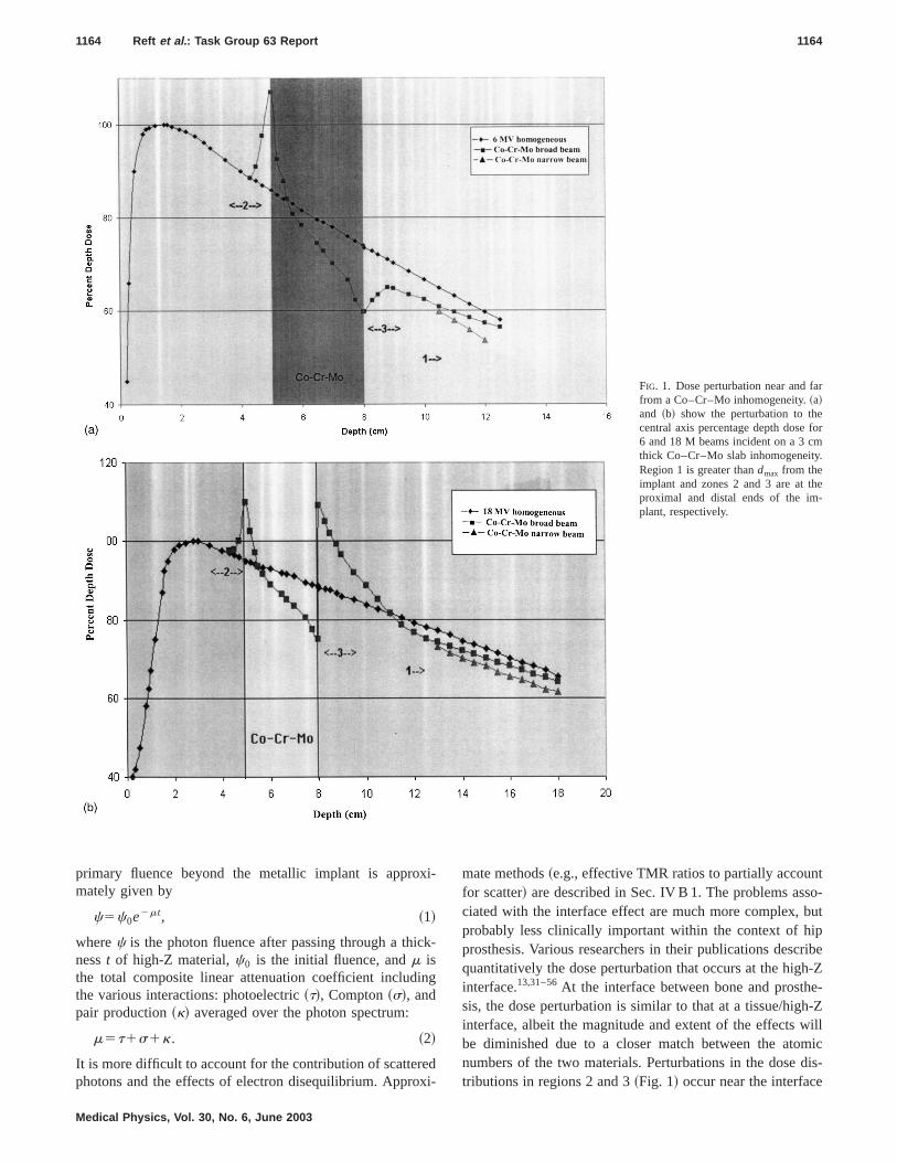
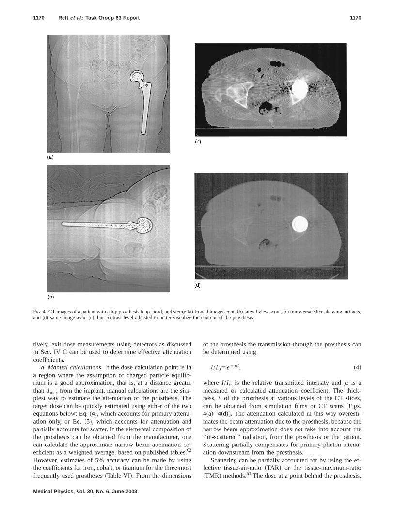
where I /I 0 is the relative transmitted intensity andm is ameasured or calculated attenuation coefficient. The thick-ness,t, of the prosthesis at various levels of the CT slices,can be obtained from simulation films or CT [email protected]~a!–4~d!#. The attenuation calculated in this way overesti-mates the beam attenuation due to the prosthesis, because thenarrow beam approximation does not take into account the‘‘in-scattered’’ radiation, from the prosthesis or the patient.Scattering partially compensates for primary photon attenu-ation downstream from the prosthesis.
Scattering can be partially accounted for by using the ef-fective tissue-air-ratio~TAR! or the tissue-maximum-ratio~TMR! methods.63 The dose at a point behind the prosthesis,
FIG. 4. CT images of a patient with a hip prosthesis~cup, head, and stem!: ~a! frontal image/scout,~b! lateral view scout,~c! transversal slice showing artifacts,and ~d! same image as in~c!, but contrast level adjusted to better visualize the contour of the prosthesis.
1170 Reft et al. : Task Group 63 Report 1170
Medical Physics, Vol. 30, No. 6, June 2003
Di , can be calculated by applying a correction factor, CF, tothe dose,Dh , at the same point in the absence of the pros-thesis.
CF5Di~d8,t !/Dh~d,t !5TMR~d8,w!/TMR~d,w!, ~5!
d85d2t~12re!. ~6!
Hered8 is the water-equivalent depth,t is the dimension ofthe prosthesis measured parallel to the axis of the beam,d isthe calculation depth,re is the electron density of the pros-thesis relative to water~Table III!, andw is the effective fieldsize. Ding and Yu9 showed that this method can adequatelypredict the dose correction factor for the prosthesis when itsmass density is used to calculate the water-equivalent depth.It was an empirical finding from their work that there wasbetter agreement between measurement and calculation us-ing the mass density rather than the electron density. As anexample, for a 1.6 cm thick Co–Cr–Mo prosthesis located ata depth of 8 cm, the dose correction factors calculated at adistance 10 cm beyond it are 0.68 and 0.78, producing anattenuation of 32% and 22% for incident 6 and 18 MV clini-cal photon beams, respectively. If the linear attenuation co-efficient method is used, Eq.~4! yields an attenuation ofabout 37% and 28% for 6 and 18 MV photons, respectively.The effective TMR method gives less attenuation because itincludes a scatter contribution. These correction methods donot take into account the dimensions of the prosthesis rela-tive to the field size or the position of the prosthesis relativeto the point of calculation. Two other approximate methodsthat partly account for the location of the prosthesis are theBatho correction and a substraction technique described byKhan63 which is similar to estimating the dose behind ablock in a radiation field.
In regions of electronic disequilibrium, which exist withindmax of the prosthesis, the previously discussed simple dosecorrection methods are not applicable. Here, the dose may beestimated using Eq.~3! and Tables I and II that provide mea-sured values for BSDF and the FDPF for metal slabs as afunction of distance from them for 6 and 18 MV photonbeams. For dose estimates near steel and titanium, Fig. 2~Ref. 56! may be used.
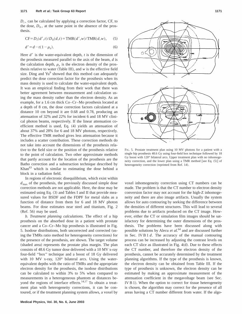
b. Treatment planning calculations. The effect of a hipprosthesis on the absorbed dose in a patient with prostatecancer and a Co–Cr–Mo hip prosthesis is illustrated in Fig.5. Isodose distributions, both uncorrected and corrected~us-ing the TMRs ratio method for heterogeneity corrections! forthe presence of the prosthesis, are shown. The target volume~shaded area! represents the prostate plus margin. The planconsists of 48.6 Gy tumor dose delivered with a 10 MV x-rayfour-field ‘‘box’’ technique and a boost of 18 Gy deliveredwith 10 MV x-ray, 120° bilateral arcs. Using the water-equivalent depths with the ratio of TMRs and the appropriateelectron density for the prosthesis, the isodose distributionscan be calculated to within 3% to 5% when compared tomeasurements in a heterogeneous phantom at distances be-yond the regions of interface effects.14,17 To obtain a treat-ment plan with heterogeneity corrections, it can be con-toured, or if the treatment planning system allows, a voxel by
voxel inhomogeneity correction using CT numbers can bemade. The problem is that the CT number to electron densityconversion factor may not account for the high-Z inhomoge-neity and there are also image artifacts. Usually the systemallows for auto contouring by seeking the difference betweenthe densities of different structures. This will lead to severalproblems due to artifacts produced on the CT image. How-ever, either the CT or simulation film images should be sat-isfactory for determining the outer dimensions of the pros-thesis. The problems have been discussed along withpossible solutions by Alecuet al.64 and are discussed furtherin Sec. IV B 1d. The accuracy of the manual contouringprocess can be increased by adjusting the contrast levels oneach CT slice as illustrated in Fig. 4~d!. Due to these effectsthe CT number, and therefore the electron density of theprosthesis, cannot be accurately determined by the treatmentplanning algorithms. If the type of the prosthesis is known,the electron density can be obtained from Table III. If thetype of prosthesis is unknown, the electron density can beestimated by making an approximate measurement of theattenuation coefficient in the megavoltage beam~see Sec.IV B 1!. When the option to correct for tissue heterogeneityis chosen, the algorithm may correct for the presence of allareas having a CT number different from water. If the algo-
FIG. 5. Prostate treatment plan using 10 MV photons for a patient with asingle hip prosthesis 48.6 Gy using four-field box technique followed by 18Gy boost with 120° bilateral arcs. Upper treatment plan with no inhomoge-neity correction, and the lower plan using a TMR method@see Eq.~5!# ofheterogeneity correction~reprinted from Ref. 14!.
1171 Reft et al. : Task Group 63 Report 1171
Medical Physics, Vol. 30, No. 6, June 2003

rithm allows, the user should correct only for specific inho-mogeneities.
The CT images cannot show whether the prosthesis ishollow or solid because the low-energy x rays used in CT donot penetrate the metallic part of the prosthesis. If informa-tion from the manufacturer is not available to determine ifthe device is solid or hollow, portal imaging with the treat-ment beam should be performed. If the prosthesis is hollow,the dimensions and geometry of the air cavity can be esti-mated from an orthogonal pair of portal images and thendrawn manually on each slice within the prosthetic head. Inthis situation the TPS should correct for both heterogeneities:metal and the air cavity. It is the responsibility of the medicalphysicist to determine how accurately the treatment planningsystem accounts for high-Z materials. Measurements in awater-equivalent phantom similar to those described byRoberts10 can be performed to test the accuracy of the systemto account for high-density materials. Alternatively, if thecomposition of the prosthesis is known, the dose calculatedby the TPS for a single beam passing through the prosthesiscan be compared to that calculated using Eq.~4! or ~5!. Thisprocedure only needs to be done once, like other tests madein commissioning the TPS.
c. Dose distribution comparison for three different modesof computing does. Here we give an example of the differ-ences in dose distribution and in monitor units~MUs! for thetreatment of the prostate using a four-field ‘‘box’’ plan for apatient with a solid steel implant for a left femur replace-ment. All beams are 18 MV and are equally weighted to givea total of 2.0 Gy to the isocenter. The dose is computed usingconvolution/superposition algorithm system~Pinnacle, Ver-sion 4.2F! in three different modes:
~1! assuming that the patient is homogeneous water~1D cal-culation!,
~2! assuming that the scatter is distributed in space as if thepatient was homogeneous, while the primary is com-puted correctly, observing the spatial distribution of den-sities ~2.5D convolution calculation!, and
~3! both primary and scatter components incorporate the dis-tribution of densities in the dose calculation~densityscaling is an approximation since the implanted Z is non-water equivalent! and performing a 3D superpositioncalculation using the collapsed cone convolution algo-rithm, where convolution kernels are scaled by the massdensity of the patient~O’Connor’s theorem!.
Table VII gives the MUs for the three modes of dosecalculation for a patient. The increase in MUs for the right
field for methods 2 and 3 is due to the presence of bone. TheMUs for the left field rise sharply as the density of the im-plant is included in the calculation. In fact the 3D calculationpredicts a slightly lower value than the 2.5D calculation.This is attributed to the differences between the two mecha-nisms to account for the scatter distribution as described ear-lier. However, if MUs are adjusted to account for attenuationthrough the prosthesis, hot spots of the order of 20% mayoccur in the normal tissue, which could be unacceptable forthe patient treatment.
d. Methods to minimize artifacts from a metal prosthesison CT images. Methods to overcome the problems caused byhigh atomic number materials by improving image recon-struction and dose calculation methodology have beenpublished,65–69 although, as yet, none are commerciallyavailable. The standard method of image reconstruction, fil-tered back projection, gives characteristic streak artifacts dueto aliasing when attempting to create images from patientscontaining high-Z materials. The loss of diagnostic qualityand corrupted density information is illustrated in Fig. 4~c!.Several attempts to overcome this limitation have been madein the past.68,69 Besides aliasing scatter, low signal-to-noise-ratio behind the prosthesis, beam hardening, or any otherphenomenon that makes CT detector response to attenuationnonlinear will degrade the image.
Future developments including megavoltage imaging us-ing tomotherapy or cone beam reconstructions or more ro-bust numerical algorithms may help produce streak-free im-ages. In selecting a CT scanner for purchase, you shouldconsider the availability and support for artifact reductionalgorithms.
2. Current TPS limitations and future possibilities
The physicist should be aware that not all commerciallyavailable TPSs allow for adjustment or manual input of CTnumbers. Also, some systems have an upper limit for theelectron density used for the heterogeneity correction algo-rithm. Table VIII provides information on some commer-cially available TPS regarding heterogeneity correction algo-rithms and their flexibility. This table provides a snapshot ofthe capabilities of TPS at this time. The medical physicistshould consult with the commercial vendors to determine thelatest capabilities of their TPS. From the data in Table VIII,all but one system allows to some degree the editing of CTnumbers and electron densities. Some groups havepublished9,69 a comparison of the results of Monte Carlosimulations to the calculations with a commercial TPS of thedose perturbation produced by a prosthesis. An illuminatingdiscussion on the differences between measurements andtreatment planning calculations is given by Roberts.10 Heshowed using one particular type of dose calculation that theaccuracy of dose calculation varies with beam energy anddepth ~e.g., behind a steel prosthesis the pencil beam algo-rithm overestimates the dose by 11% and 15% for 6 and 15MV photons, respectively!. This work illustrates the kind ofquality assurance the medical physicist should perform tounderstand the limitations of their TPS.
TABLE VII. Monitor units to deliver 2 Gy dose at isocenter with equallyweighted 18 MV beam using homogeneous, 2.5D and 3D calculation meth-ods.
Calculation Anterior Posterior Right Left
Homogeneous 57 56 70 692.5D 58 59 80 1333D 58 58 79 126
1172 Reft et al. : Task Group 63 Report 1172
Medical Physics, Vol. 30, No. 6, June 2003
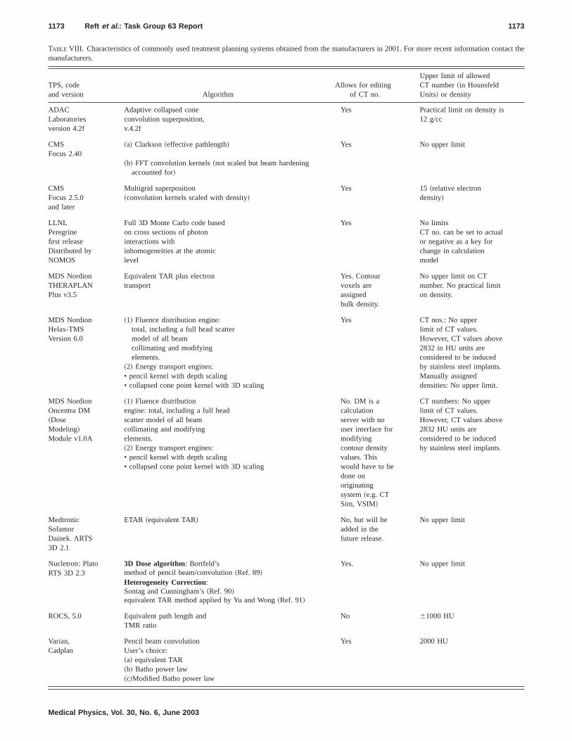
TABLE VIII. Characteristics of commonly used treatment planning systems obtained from the manufacturers in 2001. For more recent information contact themanufacturers.
TPS, codeand version Algorithm
Allows for editingof CT no.
Upper limit of allowedCT number~in HounsfeldUnits! or density
ADACLaboratoriesversion 4.2f
Adaptive collapsed coneconvolution superposition,v.4.2f
Yes Practical limit on density is12 g/cc
CMSFocus 2.40
~a! Clarkson~effective pathlength! Yes No upper limit
~b! FFT convolution kernels~not scaled but beam hardeningaccounted for!
CMSFocus 2.5.0and later
Multigrid superposition~convolution kernels scaled with density!
Yes 15~relative electrondensity!
LLNLPeregrinefirst releaseDistributed byNOMOS
Full 3D Monte Carlo code basedon cross sections of photoninteractions withinhomogeneities at the atomiclevel
Yes No limitsCT no. can be set to actualor negative as a key forchange in calculationmodel
MDS NordionTHERAPLANPlus v3.5
Equivalent TAR plus electrontransport
Yes. Contourvoxels areassignedbulk density.
No upper limit on CTnumber. No practical limiton density.
MDS NordionHelax-TMSVersion 6.0
~1! Fluence distribution engine:total, including a full head scattermodel of all beamcollimating and modifyingelements.
~2! Energy transport engines:• pencil kernel with depth scaling• collapsed cone point kernel with 3D scaling
Yes CT nos.: No upperlimit of CT values.However, CT values above2832 in HU units areconsidered to be inducedby stainless steel implants.Manually assigneddensities: No upper limit.
MDS NordionOncentra DM~DoseModeling!Module v1.0A
~1! Fluence distributionengine: total, including a full headscatter model of all beamcollimating and modifyingelements.~2! Energy transport engines:• pencil kernel with depth scaling• collapsed cone point kernel with 3D scaling
No. DM is acalculationserver with nouser interface formodifyingcontour densityvalues. Thiswould have to bedone onoriginatingsystem~e.g. CTSim, VSIM!
CT numbers: No upperlimit of CT values.However, CT values above2832 HU units areconsidered to be inducedby stainless steel implants.
MedtronicSofamorDainek. ARTS3D 2.1
ETAR ~equivalent TAR! No, but will beadded in thefuture release.
No upper limit
Nucletron: PlatoRTS 3D 2.3
3D Dose algorithm: Bortfeld’smethod of pencil beam/convolution~Ref. 89!
Yes. No upper limit
Heterogeneity Correction:Sontag and Cunningham’s~Ref. 90!equivalent TAR method applied by Yu and Wong~Ref. 91!
ROCS, 5.0 Equivalent path length andTMR ratio
No 61000 HU
Varian,Cadplan
Pencil beam convolutionUser’s choice:~a! equivalent TAR~b! Batho power law~c!Modified Batho power law
Yes 2000 HU
1173 Reft et al. : Task Group 63 Report 1173
Medical Physics, Vol. 30, No. 6, June 2003
An obstacle to accurate dose calculations is the high-Zimage reconstruction limitations discussed in Sec. IV B 1dOnce the image reconstruction algorithms are developed tosupport quantitative CT attenuation measurements of densemetal objects and artifact-free soft-tissue imaging, an accu-rate method of transporting particles is needed which ac-counts for the density and composition of the implant. Cur-rent commercial algorithms, both correction and modelbased, are unable to accurately predict the dose near highatomic number implants. The Monte Carlo methods70–72 arewell suited to this application as individual particles aretransported, with the relevant interaction cross sections beingtaken from the media through which the particles are beingtransported. Although Monte Carlo methods for radiotherapydose calculation may soon become a clinical reality, thecorrection- or model-based TPS will still be used in mostclinics in the near future.
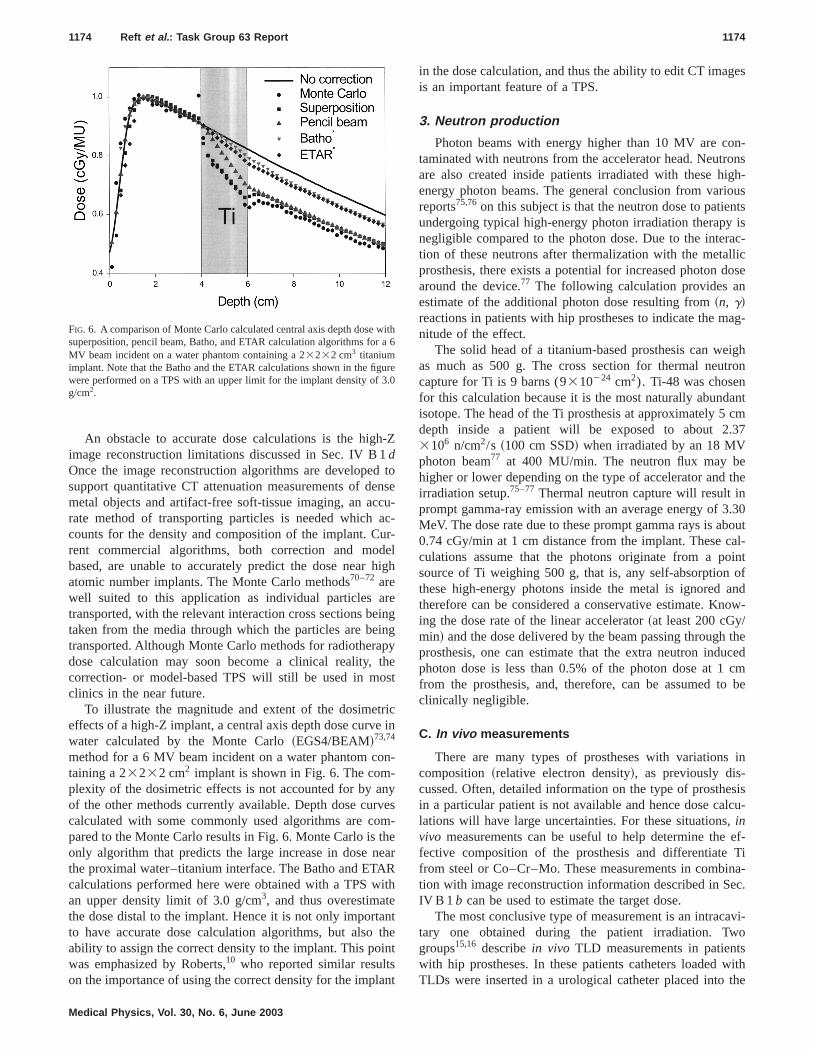
To illustrate the magnitude and extent of the dosimetriceffects of a high-Z implant, a central axis depth dose curve inwater calculated by the Monte Carlo~EGS4/BEAM!73,74
method for a 6 MV beam incident on a water phantom con-taining a 23232 cm2 implant is shown in Fig. 6. The com-plexity of the dosimetric effects is not accounted for by anyof the other methods currently available. Depth dose curvescalculated with some commonly used algorithms are com-pared to the Monte Carlo results in Fig. 6. Monte Carlo is theonly algorithm that predicts the large increase in dose nearthe proximal water–titanium interface. The Batho and ETARcalculations performed here were obtained with a TPS withan upper density limit of 3.0 g/cm3, and thus overestimatethe dose distal to the implant. Hence it is not only importantto have accurate dose calculation algorithms, but also theability to assign the correct density to the implant. This pointwas emphasized by Roberts,10 who reported similar resultson the importance of using the correct density for the implant
in the dose calculation, and thus the ability to edit CT imagesis an important feature of a TPS.
3. Neutron production
Photon beams with energy higher than 10 MV are con-taminated with neutrons from the accelerator head. Neutronsare also created inside patients irradiated with these high-energy photon beams. The general conclusion from variousreports75,76on this subject is that the neutron dose to patientsundergoing typical high-energy photon irradiation therapy isnegligible compared to the photon dose. Due to the interac-tion of these neutrons after thermalization with the metallicprosthesis, there exists a potential for increased photon dosearound the device.77 The following calculation provides anestimate of the additional photon dose resulting from~n, g!reactions in patients with hip prostheses to indicate the mag-nitude of the effect.
The solid head of a titanium-based prosthesis can weighas much as 500 g. The cross section for thermal neutroncapture for Ti is 9 barns (9310224 cm2). Ti-48 was chosenfor this calculation because it is the most naturally abundantisotope. The head of the Ti prosthesis at approximately 5 cmdepth inside a patient will be exposed to about 2.373106 n/cm2/s ~100 cm SSD! when irradiated by an 18 MVphoton beam77 at 400 MU/min. The neutron flux may behigher or lower depending on the type of accelerator and theirradiation setup.75–77Thermal neutron capture will result inprompt gamma-ray emission with an average energy of 3.30MeV. The dose rate due to these prompt gamma rays is about0.74 cGy/min at 1 cm distance from the implant. These cal-culations assume that the photons originate from a pointsource of Ti weighing 500 g, that is, any self-absorption ofthese high-energy photons inside the metal is ignored andtherefore can be considered a conservative estimate. Know-ing the dose rate of the linear accelerator~at least 200 cGy/min! and the dose delivered by the beam passing through theprosthesis, one can estimate that the extra neutron inducedphoton dose is less than 0.5% of the photon dose at 1 cmfrom the prosthesis, and, therefore, can be assumed to beclinically negligible.
C. In vivo measurements
There are many types of prostheses with variations incomposition ~relative electron density!, as previously dis-cussed. Often, detailed information on the type of prosthesisin a particular patient is not available and hence dose calcu-lations will have large uncertainties. For these situations,invivo measurements can be useful to help determine the ef-fective composition of the prosthesis and differentiate Tifrom steel or Co–Cr–Mo. These measurements in combina-tion with image reconstruction information described in Sec.IV B 1 b can be used to estimate the target dose.
The most conclusive type of measurement is an intracavi-tary one obtained during the patient irradiation. Twogroups15,16 describein vivo TLD measurements in patientswith hip prostheses. In these patients catheters loaded withTLDs were inserted in a urological catheter placed into the
FIG. 6. A comparison of Monte Carlo calculated central axis depth dose withsuperposition, pencil beam, Batho, and ETAR calculation algorithms for a 6MV beam incident on a water phantom containing a 23232 cm3 titaniumimplant. Note that the Batho and the ETAR calculations shown in the figurewere performed on a TPS with an upper limit for the implant density of 3.0g/cm2.
1174 Reft et al. : Task Group 63 Report 1174
Medical Physics, Vol. 30, No. 6, June 2003

bladder and irradiated during part of a treatment session. Thelocation of the TLDs with respect to the patient’s anatomywas verified using metal markers. The results of the TLDmeasurements of Burlesonet al.17 showed a 10% to 15%dose reduction for a conventional four-field beam geometryin a patient with bilateral total hip replacement prostheses.Hazukaet al.15 compared theirin vivo TLD results with het-erogeneity corrected dose calculations using the ratio of theTMR correction algorithm, and an estimated thickness of theprosthesis from CT. The difference between the measuredand calculated doses was only 3%. Unfortunately, their TLDcalibrations had a rather large error~8.3%, 1 SD!. An obvi-ous limitation of this type ofin vivo measurement is theadded inconvenience and discomfort for the patient, and isunlikely to be performed. Instead,in vivo dosimetry usingdetectors positioned on the skin of the patient and at the exitsurface of the beam is often used as a method to assess thedose inside the patient.78–81 Many exit dose measurementsrelating to hip prostheses described in the literature are per-formed with diodes. However, thermoluminescent detectors~TLDs! and film have also been used. If film is used, a cali-bration curve for the particular type of film should also beobtained. Those interested in performing these types of mea-surements should consult the ESTRO booklet82 which pro-vides a comprehensive literature review on the clinical use ofboth diodes and TLDs and an ESTRO publication83 on per-forming in vivo dosimetry with a diode.
The exit dose for the beam passing through prosthesis iscalculated from a detector reading using the equation
De5R3K3II iCi , ~7!
whereDe is the exit dose,R is the detector reading,K is thedetector calibration factor measured under referenceconditions,77–81and II iCi are a product of correction factorsfor the different detectors under nonreference irradiationconditions. TheseCi factors are related to the type of detec-tor. For example, ionization chambers will have correctionsfor recombination and temperature and pressure, diodes willhave corrections for dose rate and angular response, and filmmay have corrections for scattering conditions. The sub-script,e, refers to the actual measurement condition for mea-suring the exit dose. The attenuation of the beam producedby the prosthesis at a point along a given ray can now beobtained by calculating the transmission through the prosthe-sis as a ratio of the exit dose measured in the shadow of theprosthesis and the dose at the same point, calculated by theTPS, for a homogeneous case~neglecting the presence of theprosthesis!. The attenuation estimated in this way, at the exitsurface, is 2% to 6% lower than the actual broad beam at-tenuation depending upon the energy, patient separation, andfield size. This is because internal scatter will partially cancelthe attenuation effect of the prosthesis at distances distal tothe inhomogeneity. This is a small effect compared to theattenuation introduced by the prosthesis in the target volume.The accuracy ofin vivo dosimetry is very dependent on theimmobilization of the patient and the accurate positioning ofthe patient and detector. However, exit dose measurements
can provide an estimate of the error in TPS calculations, ifthe heterogeneity correction option is activated.
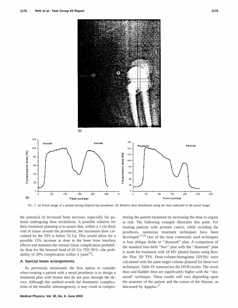
A drawback ofin vivo dosimetry using diodes or TLDs isthat the dose is only measured at a limited number of pointsinstead of over the shadow of the target. One method toobtain spatial dose information is to use film as described byVan Damet al.84 A promising approach is to use the infor-mation in a portal image to verify the dose calculation. Rela-tive dose distributions transmitted through the patient, ob-tained with a portal image, can be used to determine theradiological path length through the prosthesis. This can bedone by measuring dose profiles through the projection ofthe prosthesis after converting the optical density of a film,or the pixel values of an image of an electronic portal imag-ing device, into dose values.85 The resulting reduction intransmission at the position of the prosthesis, compared withadjacent values, can then be converted into a radiologicalpath length that can be used for dose calculation as illus-trated in Figs. 7~a! and 7~b!. Currently, several groups havedeveloped methods85–87 to relate the information in the por-tal image directly to the dose distribution in the patient.However, these methods are still evolving and slowly com-ing into clinical use, and the rather complicated algorithmsfor patient dose calculations are not yet widely available.Therefore, in the near future, only the simple relative meth-ods described previously are likely to be available for clini-cal needs.
V. POSSIBLE ACTIONS FOR MINIMIZINGTHE DOSE PERTURBATIONS
Perturbations of the dose distribution by a hip prosthesiswhen treating pelvic malignancies can result in unacceptabledose inhomogeneities within the target volume. Such an in-homogeneous dose distribution may compromise local con-trol and, therefore, beam arrangements to completely orpartly avoid the prosthesis~e.g., avoid using or reduce theweight of the lateral beam on the side of the prosthesis orconsider using rotational fields! have been proposed, and areoften the preferred solution. Sometimes these techniques arenot the best choice since the dose to organs at risk may beunacceptably high. Tolerance doses to normal tissue can befound in the literature.59 Therefore, alternative methods tocompensate for the beam attenuation due to the prosthesismay be more suitable. In determining a course of action, it isimportant to consult closely with the radiation oncologistregarding the treatment goals. For patients treated to a lowprescription dose, the dose perturbation caused by one of thefields traversing part or all of the prosthesis may still producea clinically acceptable isodose distribution in the normal tis-sue. Alternatively, a simple heterogeneity correction to adjustthe treatment MUs may provide an acceptable plan. In eithercase the normal tissue consequences of either changing thebeam arrangements or giving more MUs through the pros-thesis are reduced for low treatment doses. However, patientstreated to a high prescription dose may require a more so-phisticated treatment plan. In particular, due to the uncer-tainty in the dose calculations near a high-Z material, there is
1175 Reft et al. : Task Group 63 Report 1175
Medical Physics, Vol. 30, No. 6, June 2003
the potential of increased bone necrosis, especially for pa-tients undergoing dose escalations. A possible solution fortheir treatment planning is to assure that, within a 1 cmthickrind of tissue around the prosthesis, the maximum dose cal-culated by the TPS is below 55 Gy. This would allow for apossible 15% increase in dose to the bone from interfaceeffects and maintain the normal tissue complication probabil-ity dose for the femoral head of 65 Gy~TD 50/5—the prob-ability of 50% complication within 5 years59!.
A. Special beam arrangements
As previously mentioned, the first option to considerwhen treating a patient with a metal prosthesis is to design atreatment plan with beams that do not pass through the de-vice. Although this method avoids the dosimetric complica-tions of the metallic inhomogeneity, it may result in compro-
mising the patient treatment by increasing the dose to organsat risk. The following example illustrates this point. Fortreating patients with prostate cancer, while avoiding theprosthesis, numerous treatment techniques have beendeveloped.27,28 One of the most commonly used techniquesis four oblique fields or ‘‘diamond’’ plan. A comparison ofthe standard four-field ‘‘box’’ plan with the ‘‘diamond’’ planis made for treatment with 18 MV photon beams using Ren-der Plan 3D TPS. Dose-volume-histograms~DVHs! werecalculated with the same target volume planned for these twotechniques. Table IX summarizes the DVH results. The rectaldose and bladder dose are significantly higher with the ‘‘dia-mond’’ technique. These results will vary depending uponthe anatomy of the patient and the extent of the disease, asdiscussed by Agapito.27
FIG. 7. ~a! Portal image of a patient having bilateral hip prostheses.~b! Relative dose distribution along the lines indicated in the portal image.
1176 Reft et al. : Task Group 63 Report 1176
Medical Physics, Vol. 30, No. 6, June 2003

Examples of alternate beam arrangements to avoid treat-ing through a hip prosthesis are presented. One technique fortreating cancer of the prostate involves six high-energy pho-ton beams: two opposed lateral fields and two pairs of op-posed oblique fields. Figure 8~a! shows the central axis iso-dose distribution without inhomogeneity correction for 18MV photons for six fields superimposed on a transverse CTcut through the prostate. To avoid the prosthesis three differ-ent treatment plans were developed for this patient: a five-field plan @Fig. 8~b!#, a five-field plan with [email protected]~c!#, and a three-field plan with wedges@Fig. 8~d!#. Theseplans are provided as examples of treatment options thatavoid the metallic prosthesis. The optimal plan for coveringthe target and minimizing the dose to the critical structuresdepends upon the patient anatomy and the extent and loca-tion of the disease. To compare the plans the integral DVHsare shown in Fig. 9. All the plans completely cover the tar-get, but there are significant differences in the dose to therectum and bladder among these three plans. Although theDVH for the three-field plan shows significant sparing of therectum, this must be weighed against the increased dose tothe right femoral head illustrated by the isodose distributionin Fig. 8~d!. In appropriate cases more complex non-coplanarbeam arrangements may be considered. However, theseshould be weighed against the practical issues such as ease oftreatment planning and delivery, gantry-couch collision, por-tal verification, and staff training. Therefore, the advantagesand disadvantages of modified treatment techniques to avoiddosimetric complications should be carefully considered anddiscussed with the radiation oncologist.
B. Dose compensation
There are two general methods to correct for the effect ofa prosthesis on target dose distribution. In one method for-ward planned intensity modulated beams are used to com-pensate beams that traverse the prosthesis while in the othermethod inverse planned intensity modulated beams are usedto provide normal tissue protection and target coverage withbeams that avoid the prosthesis. In the former method twodose compensation techniques have been reported by Alecuet al.64 The first technique uses a traditional compensator.The other uses manually created intensity modulated x-raybeams using a multileaf collimator. In the first method thedose information available from a portal image is taken toconstruct a physical compensator filter. A limitation of such acompensator system is that it cannot be used for patientswith bilateral hip prostheses. This problem may be overcomewith the second method. A dose compensator is designed
FIG. 8. ~a! Transverse isodose distribution through the central axis for asix-field plan: Two opposed lateral fields and two pairs of opposed obliquefields using 18 MV photons. The following three field arrangements aredesigned to avoid the prosthesis.~b! Five-field plan: two anterior obliquefields, two posterior oblique fields and a right lateral field for 18 MV pho-tons. ~c! A five-field plan with wedges: two anterior oblique fields, twoposterior oblique fields, and a right lateral field for 18 MV photons. All ofthe oblique fields have a 30° wedge.~d! A three-field plan with wedges: 6MV anterior field with a 45° wedge, 18 MV posterior field with a 30°wedge, and 18 MV right lateral field with a 15° wedge. In all of these plansthe field sizes are adjusted to conform to the target and the dose distributionsare obtained with PLUNC, Plan University of North Carolina, 3D treatmentplanning system.
TABLE IX. Summary of DVHs.
Four field box Diamond
Rectum 100% Vol>50% Dose 100% Vol>50% Dose38% Vol gets 100% Dose 99% Vol gets 100% Dose
Bladder 60% Vol>50% Dose 77% Vol>50% Dose8% gets 100% Dose 36% Vol gets 100% Dose
19%<20% Dose 16% Vol<20% Dose
1177 Reft et al. : Task Group 63 Report 1177
Medical Physics, Vol. 30, No. 6, June 2003

using a CT simulation, 3D treatment planning, and multileafcollimators to produce segmental fields that allow high in-tensity over the prosthesis. These methods of dose compen-sation produce a high dose perturbation in the normal tissueupstream of the prosthesis, which should be evaluated. These
techniques require accurate characterization of the prosthesisgeometry, accurate dosimetry modeling in the presence ofthe metallic implant, as well as good patient immobilizationand accurate registration of the compensator to the patient.Precautions similar to those in treatment planning should betaken for the design of the compensator. Additionally,in vivomeasurements should be performed to verify its accuracy.Because of these factors and the labor involved in designingand constructing the compensators~less labor is involvedusing a multileaf collimator!, they will probably be of lim-ited use in a busy clinic that does not have the necessaryphysics and technical support.
An example of the latter method is intensity modulatedradiation therapy~IMRT! with dynamic multileaves as in thestep-and-shoot method in combination with inverse treat-ment planning. This treatment modality is becoming moreavailable and potentially offers better treatment plans for theprostate. By making the prosthesis a critical structure toavoid or choosing beams that avoid it, treatment plans can bedeveloped using inverse treatment planning techniques88 thatare comparable to the commonly used six-field technique.Alternatively, to provide more flexibility in developing treat-ment plans, the prosthesis can be selected as a critical struc-ture with a dose constraint. One study88 compares conformalsix-field and five-field plans with a nine-field IMRT plan. Asan example, Fig. 10 shows the comparison of DVHs for thebladder, rectum, and PTV for a five-field 3D conformal 18MV plan and a nine-field 6 MV IMRT plan for a patient witha prosthesis. A six-field 18 MV plan with the inhomogeneitycorrection turned off is shown as a reference for comparison.The IMRT plan compares favorably with the reference plan.
VI. RECOMMENDATIONS
This Task Group recommends the following protocol:
~1! Find out from your treatment planning system manufac-turer the possibilities and limitations regarding heteroge-neity corrections for high electron densities of the treat-ment planning algorithm available within yourdepartment. Determine and test if electron densities canbe changed in user-selected regions, if there is an upperlimit to this value and how to edit the streak artifacts~seeTable VIII and Sec. IV B 1b!. Verify this informationwith some phantom measurements such as those de-scribed by Roberts10 or with hand calculations.
~2! The radiation oncologist should inform the physicist inadvance if a patient with a hip prosthesis is scheduled tobe simulated for pelvic radiation.
~3! Beam arrangements that avoid the prosthesis should beconsidered first, and this option should be discussed withthe radiation oncologist.
~4! If the decision is made to use a technique with beamswhich avoid the prosthesis, the following additionalsteps are recommended:4.1 Use standard immobilization and simulation or CTsimulation.4.2 Perform treatment planning. Check with the simula-tor films and/or DRRs that the prosthesis does not
FIG. 9. Summary of the dose volume histograms for the target, bladder, andthe rectum for the four different treatment techniques as shown in Figs.9~a!–9~d!.
1178 Reft et al. : Task Group 63 Report 1178
Medical Physics, Vol. 30, No. 6, June 2003

shadow part of the target volume. For CT planning youcan edit out the streak artifacts and turn off the inhomo-geneity correction.4.3 Take a port film or EPID image before or during thefirst treatment to verify that the prosthesis does notshadow part of the target volume.
~5! If treatment through the prosthesis is considered, thenthe following are recommended.5.1 Discuss with the radiation oncologist the treatmentplan for this patient. Include such questions as:
5.1.1. Is the patient getting a high or low target dose?5.1.2. Is the dose to the bladder, rectum, or hip of
concern?5.1.3. What uncertainty in the target dose is accept-
able?5.2. Obtain before simulation as much data as possibleabout the prosthesis from the patient’s medical records,the surgeon, and/or prosthesis manufacturer.5.3. Inform the radiation oncologist about the approxi-mate magnitude of the relevant dose perturbation and thecapabilities of your TPS to make the corrections.5.4. If the type of prosthesis is known, then the followingsteps are recommended:
5.4.1. Obtain the physical characteristics such as itsdimensions from orthogonal simulator films or CTscouts, electron density~to use in planning, if necessary!,approximate attenuation of the beam passing through theprosthesis, and possible dose increase to the hip bone,
etc. from this report or other sources.12,14
5.4.2. Perform treatment planning~computerized iso-dose distributions with heterogeneity corrections, input-ting the electron density!. Use the most physically rigor-ous dose calculation algorithm available in your TPS.
5.4.3. Use published data on prosthesis attenuationand electron densities to compare your hand and treat-ment planning calculations.
5.4.4. Treat the first fraction based on 5.4.1 and takeportal images and confirm whether the prosthesis is hol-low or solid.
5.4.5. During the first fraction perform exit dose mea-surements with diodes, films, or TLDs to confirm and, ifnecessary, modify your treatment planning calculationsand input characteristics.5.5. If there are no data available on the physical char-acteristics, but the composition of the prosthesis isknown, perform phantom measurements or a calculationfor the attenuation~see Sec. IV B 1a! and continuethrough steps 5.4.1–5.4.5.5.6. If the type and characteristic of the prosthesis areunknown, then the following steps are recommended:
5.6.1. Perform treatment planning~computerized iso-dose distribution without heterogeneity corrections in or-der to calculate attenuation—Sec. IV B!.
5.6.2. Check with the physician if films only~no treat-ment! can be taken on the first day to obtain informationon the prosthesis. If not, treat the first fraction ignoring
FIG. 10. DVHs for the bladder~a!, rectum ~b!, and PTV~c! comparing five-field 3DCRT and IMRT plans. The six-field 3DCRT DVHs are shown forcomparison. The conformal plans obtained with PLUNC~Plan University of North Carolina! and the IMRT plan obtained with CORVUS inverse treatmentplanning system.
1179 Reft et al. : Task Group 63 Report 1179
Medical Physics, Vol. 30, No. 6, June 2003

the presence of the prosthesis based on 5.6.1.5.6.3. During the first fraction:5.6.3.1. Take port film or EPID and determine if pros-
thesis is solid or hollow.5.6.3.2. Perform exit dose measurements with EPID,
films, diodes, or TLDs~diodes will show up on portalfilms or EPID images!.
5.6.4. Use these measured data to derive physicalproperties of the prosthesis, such as attenuation of thebeam due to the prosthesis, which might allow you toidentify the type of prosthesis and compare your resultswith published data.
5.6.5. Perform treatment planning~computerized iso-dose distribution with heterogeneity corrections! basedon your calculated and measured data. Use the most ac-curate dose calculation algorithm available in your TPS.
5.6.6. During the second fraction perform exit dosemeasurements with detectors to confirm, and if neces-sary modify your treatment planning calculations and in-put characteristics. If the patient has more than 30 frac-tions, it might be acceptable to the physician for thepatient to be treated with the original plan for the firstfew fractions while a more accurate treatment plan isdeveloped.5.7. Document the treatment plan and procedure usedand inform the radiation oncologist about
5.7.1. The effect of the prosthesis on the target dosedistribution and the uncertainty in estimating this effect,
5.7.2. The approximate magnitude of the interface ef-fect, and
5.7.3. The possible increase in dose for organs at risk,peripheral tissue, etc.
Suggestions for future research work include the develop-ment of algorithms to reduce the streaking artifacts producedwhen reconstructing CT images of patients with prosthesis aswell as algorithms to calculate accurately dose distributionsnear high-Z materials. Further study should also be per-formed on the biological effects of the increased tissue doseat the tissue-prosthesis interface.
ACKNOWLEDGMENTS
The Task Group members would like to thank Dr. GeorgeDing for performing the ETAR and Batho calculations dis-played in Fig. 6. We also would like to acknowledge thecontributions to this report from Dr. Mary Hebert, Dr. MariusAlecu, Dr. Sam Beddar, and Dr. Radhe Mohan. Also, theTask Group is greatly thankful to Ellen Yorke for her verythorough reviews and constructive editing of the various ver-sions during the drafting of this document.
1B. J. Mijnheer, ‘‘The clinical basis for dosimetric accuracy in radio-therapy,’’ in Radiation Incidents~British Institute of Radiology, London,1996!, pp. 16–20.
2G. H. Fletcher,Textbook of Radiotherapy~Lea and Febiger, Piladelphia,1981!.
3ICRU 50 ~ICRU Report 50!, Prescribing, Recording, and Reporting Pho-ton Beam Therapy~International Commission on Radiation Units andMeasurements, Bethesda, MD, 1993!.
4ICRU 62 ~ICRU Report 62!, Prescribing, Recording and Reporting Pho-ton Beam Therapy (Supplement to ICRU Report 50)~International Com-mission on Radiation Units and Measurements, Bethesda, MD, 1999!.
5TG-21, ‘‘A protocol for the determination of absorbed dose from high-energy photon and electron beams,’’ Med. Phys.10, 741–771~1983!.
6TG-51, ‘‘AAPM’s TG-51 protocol for clinical reference dosimetry ofhigh-energy photon and electron beams,’’ Med. Phys.26, 1847–1870~1999!.
7TRS No. 398,Absorbed Dose Determination in External Beam Radio-therapy: An International Code of Practice for Dosimetry on Standardsof Absorbed Dose to Water~IAEA, Vienna, 2000!.
8P. W. Grigsby, H. L. Roberts, and C. A. Perez, ‘‘Femoral neck fracturefollowing groin irradiation,’’ Int. J. Radiat. Oncol., Biol., Phys.32, 63–67~1995!.
9G. X. Ding and C. W. Yu, ‘‘A study on beams passing through hip-prosthesis for pelvic radiation treatment,’’ Int. J. Radiat. Oncol., Biol.,Phys.51, 1167–1175~2001!.
10R. Roberts, ‘‘How accurate is a CT-based dose calculation on a pencilbeam TPS for a patient with a metallic prosthesis,’’ Phys. Med. Biol.46,N227–N234~2001!.
11P. J. Biggs and M. D. Russell, ‘‘Effect of a femoral head prosthesis onmegavoltage beam radiotherapy,’’ Int. J. Radiat. Oncol., Biol., Phys.14,581–586~1988!.
12C. H. Sibata, H. C. Mota, P. D. Higgins, D. Gaisser, J. P. Saxton, and K.H. Shin, ‘‘Influence of hip prostheses on high energy photon dose distri-bution,’’ Int. J. Radiat. Oncol., Biol., Phys.18, 455–461~1990!.
13I. J. Das, K. R. Kase, A. S. Meigooni, F. M. Khan, and B. L. Werner,‘‘Validity of transition-zone dosimetry at high atomic number interfacesin megavoltage photon beams,’’ Med. Phys.17, 10–16~1990!.
14M. B. Hazuka, G. S. Ibbott, and J. J. Kinzie, ‘‘Hip prostheses duringpelvic irradiation: effects and corrections,’’ Int. J. Radiat. Oncol., Biol.,Phys.14, 1311–1317~1988!.
15M. B. Hazuka, D. N. Stoud, J. Adams, G. S. Ibbott, and J. J. Kinzie,‘‘Prostatic thermoluminescent dosimeter analysis in a patient treated with18 MV x rays through a prostheic hip,’’ Int. J. Radiat. Oncol., Biol., Phys.25, 339–343~1993!.
16F. R. Hudson, M. T. Crawley, and M. Samarasekera, ‘‘Radiotherapy treat-ment planning for patients fitted with prostheses,’’ Br. J. Radiol.57, 603–608 ~1984!.
17W. D. Burleson, C. D. Stutzman, J. A. Stitt, U. L. Karlsson, and T. A.Mian, ‘‘In vivo isocenter dose in two hip prosthesis patients,’’ Int. J.Radiat. Oncol., Biol., Phys.20, 1347–1352~1991!.
18M. Erlanson, L. Franzen, R. Henriksson, B. Littbrand, and P. Lofroth,‘‘Planning of radiotherapy for patients with hip prosthesis,’’ Int. J. Radiat.Oncol., Biol., Phys.20, 1093–1098~1991!.
19N. Scher, D. Poe, F. Kuchnir, C. Reft, R. Weichselbaum, and W. R. Panje,‘‘Radiotherapy of the resected mandible following stainless steel platefixation,’’ Laryngoscope98, 561–563~1988!.
20M. H. Castillo, T. M. Button, R. Doerr, M. I. Homs, C. W. Pruett, and J.I. Pearce, ‘‘Effects of radiotherapy on mandibular reconstruction plates,’’Am. J. Surg.156, 261–263~1988!.
21R. R. Wang, K. Pillai, and P. K. Jones, ‘‘In vitro backscattering fromimplant materials during radiotherapy,’’ J. Prosthet. Dent.75, 626–632~1996!.
22R. Wang, K. Pillai, and P. K. Jones, ‘‘Dosimetric measurement of scat-tered radiation from dental implants in simulated head and neck radio-therapy,’’ Int. J. Oral Maxillofac Implants13, 197–203~1998!.
23D. P. Fontenla, M. Ahmad, C. S. Chui, B. McCormick, D. H. Abramson,and G. J. Kutcher, ‘‘Effect of occular implants of different materials onthe dosimetry of external beam radiation therapy,’’ Int. J. Radiat. Oncol.,Biol., Phys.32, 1477–1480~1995!.
24T. J. Nelson and S. C. Sharma, ‘‘Irradiating with a prosthesis or metal pinin the radiation treatment field,’’ Med. Dosim13, 113–118~1988!.
25P. M. Mondalek and J. M. Fayad, ‘‘Prostatic adenocarcinoma: treatmentplanning consideration with a hip prosthesis,’’ Med. Dosim.8~2!, 5–6~1983!.
26M. D. C. Evans, H. J. Patrocinio, L. Souhami, M. Tanzer, and E. B.Podgorsak, ‘‘Dosimetry of hip irradiation for prevention of heterotopicbone formation after arthroplasty,’’ Int. J. Radiat. Oncol., Biol., Phys.43,1161–1165~1999!.
27J. Agapito, ‘‘Radical radiation therapy for carcinoma of the prostate inpatients with single hip prosthesis: A technique analysis using dose-volume histograms,’’ Med. Dosim.26, 243–250~2001!.
1180 Reft et al. : Task Group 63 Report 1180
Medical Physics, Vol. 30, No. 6, June 2003
28S. E. Schild, J. S. Robinow, H. E. Casale, L. P. Bellefontaine, and S. J.Buskirk, ‘‘Radiotherapy treatment planning for prostate cancer in patientswith prosthetic hips,’’ Med. Dosim.17, 83–86~1992!.
29T. Y. Eng, ‘‘Dose attenuation through a titanium alloy hip prosthesis,’’Med. Dosim.25, 7–8 ~2000!.
30E. Melian, M. Fatyga, P. Lam, M. Steinberg, S. P. Reddy, G. J. Petruz-zelli, and G. P. Glasgow, ‘‘Effect of metal reconstruction plates onCobalt-60 dose distribution: A predictive formula and clinical implica-tions,’’ Int. J. Radiat. Oncol., Biol., Phys.44, 725–730~1999!.
31I. J. Das and F. M. Khan, ‘‘Backscatter dose perturbation at high atomicnumber interfaces in megavoltage photon beams,’’ Med. Phys.16, 367–375 ~1989!.
32O. A. Sauer, ‘‘Calculation of dose distributions in the vicinity of high-Zinterfaces for photon beams,’’ Med. Phys.22, 1685–1690~1995!.
33F. W. Spiers, ‘‘The influence of energy absorption and electron range ondosage in irradiated bone,’’ Br. J. Radiol.22, 521–533~1949!.
34F. W. Spiers, ‘‘Dosage in irradiated soft tissue and bone,’’ Br. J. Radiol.25, 365–370~1951!.
35E. R. Epp, H. Q. Woodard, and H. Weiss, ‘‘Energy absorption by the bonemarrow of the mouse receiving whole-body irradiation with 250-KVx-rays or cobalt-60 gamma rays,’’ Radiat. Res.11, 184–197~1959!.
36W. K. Sinclair, ‘‘The relative biological effectiveness of 22-MV x-rays,cobalt-60 gamma rays, and 200-kVp x-rays. Absorbed dose to the bonemarrow in the rat and the mouse,’’ Radiat. Res.16, 369–383~1962!.
37C. L. Wingate, W. Gross, and G. Failla, ‘‘Experimental determination ofabsorbed dose from x-rays near the interface of soft tissue and othermaterial,’’ Radiology79, 984–1000~1962!.
38S. L. Hood and G. Morris, ‘‘Dosimetry of human cell cultures irradiatedat the interface in plastic and glass dishes,’’ Radiat. Res.14, 705–712~1961!.
39N. Aspin and H. E. Johns, ‘‘The absorbed dose in cylindrical cavitieswithin irradiated bone,’’ Br. J. Radiol.36, 350–362~1963!.
40I. J. Das and K. L. Chopra, ‘‘Backscatter dose perturbation in kilovoltagephoton beams at high atomic number interfaces,’’ Med. Phys.22, 767–773 ~1995!.
41I. J. Das, ‘‘Forward dose perturbation at high atomic number interfaces inkilovoltage X-ray beams,’’ Med. Phys.24, 1781–1787~1997!.
42H. Q. Woodard and J. S. Laughlin, ‘‘The effect of x-rays of differentqualities on the alkaline phosphatase of living mouse bone,’’ Radiat. Res.7, 236–252~1957!.
43J. Dutreix, A. Dutreix, and M. Bernard, ‘‘Etude de la dose au voisinagede l’interface entre deux milieux de composition atomique diffe´rente ex-poses aux rayonnement y du60Co,’’ Phys. Med. Biol.7, 69–82~1962!.
44J. Dutreix and M. Bernard, ‘‘Dosimetry at interfaces for high energy Xand gamma rays,’’ Br. J. Radiol.39, 205–210~1966!.
45S. Webb, ‘‘The absorbed dose in the vicinity of an interface between twomedia irradiated by a60Co source,’’ Br. J. Radiol.52, 962–967~1979!.
46B. L. Werner, I. J. Das, F. M. Khan, and A. S. Meigooni, ‘‘Dose pertur-bations at interfaces in photon beams,’’ Med. Phys.14, 585–595~1987!.
47B. L. Werner, I. J. Das, and W. N. Salk, ‘‘Dose perturbations at interfacesin photon beams: secondary electron transport,’’ Med. Phys.17, 212–226~1990!.
48B. J. Mijnheer, R. K. Rice, and L. M. Chin, ‘‘Lead-polystyrene transitionzone dosimetry in high-energy photon beams,’’ Radiother. Oncol.11,379–386~1988!.
49I. J. Das. ‘‘Study of Dose Perturbation at Bone-Tissue Interfaces in Mega-voltage Photon Beam Therapy,’’ Ph.D. thesis, University of Minnesota,1988.
50A. Niroomand-Rad, R. Razavi, S. Thobejane, and K. W. Harter, ‘‘Radia-tion dose perturbation at tissue-titanium dental interfaces in head andneck cancer patients,’’ Int. J. Radiat. Oncol., Biol., Phys.34, 475–480~1996!.
51T. A. Mian, M. C. Van Putten, D. C. Kramer, R. F. Jacob, and A. L.Boyer, ‘‘Backscatter radiation at bone-titanium interface from high-energy X and gamma rays,’’ Int. J. Radiat. Oncol., Biol., Phys.13, 1943–1947 ~1987!.
52V. Thambi, A. Murthy, G. Alder, and P. Kartha, ‘‘Dose perturbation re-sulting from gold fillings in patients with head and neck cancers,’’ Int. J.Radiat. Oncol., Biol., Phys.5, 581–582~1979!.
53M. Murthy and A. Lakshmanan, ‘‘Dose enhancement due to backscat-tered secondary electrons at the interface of two media,’’ Radiat. Res.67,215–223~1976!.
54G. A. Carlsson, ‘‘Dosimetry at plane interfaces between a low Z-material
and Al, Cu, Sn or Pb irradiated with 100 to 200 kV roentgen radiation.Theoretical analysis and measurements by means of thermoluminescentLiF,’’ Acta Radiol., Suppl.332, 1–64~1973!.
55K. M. Stenson, J. M. Balter, J. H. Campbell, and C. R. Carroll, ‘‘Effectsof implantable biomaterials on radiation dosimetry,’’ Head Neck19,384–390~1997!.
56P. J. Gullane, ‘‘Primary Mandibular reconstruction analysis of 64 casesand evaluation of interface radiation dosimetry on bridging plates,’’Laryngoscope101~6, pt. 2!, 1–24~1991!.
57R. Nadrowitz and T. Feyerabend, ‘‘Backscatter dose from metallic mate-rials due to obliquely incident high-energy photon beams,’’ Med. Phys.28, 959–965~2001!.
58C. S. Reft and F. T. Kuchnir, ‘‘Dose correction factors at the bone-tissueinterface for high energy photon beams,’’ Med. Phys.13, 942 ~1986!.
59B. Emami, J. Lyman, A. Brown, L. Coia, M. Goiten, J. E. Munzenrider,B. Shank, L. J. Solin, and M. Wesson, ‘‘Tolerance of normal tissue totherapeutic irradiation,’’ Int. J. Radiat. Oncol., Biol., Phys.21, 109–122~1991!.
60K. Shimanovskaya and A. D. Shiman,Radiation Injury of Bone: BoneInjuries Following Radiation Therapy of Tumors~Pergamon, New York,1983!.
61J. Kirchner and R. Bowman,Effects of Radiation on Materials and Com-ponents~Reinhold, New York, 1964!.
62National Institute of Standards and Technology~NIST!,www.physics.nist.gov/PhysRefData/XrayMassCoef
63F. M. Khan, The Physics of Radiation Therapy, 2nd ed.~Williams &Wilkins, Baltimore, 1994!.
64R. Alecu, M. Alecu, T. Loomis, T. Ochran, and T. He, ‘‘Traditional andMLC based dose compensator design for patients with hip prosthesesundergoing pelvic radiation therapy,’’ Med. Dosim24, 33–37~1999!.
65G. Wang, D. L. Snyder, and A. O. O’Sullivan, ‘‘Iterative deblurring forCT metal artifact removal,’’ IEEE Trans. Med. Imaging15, 657–664~1996!.
66R. L. Morin and D. E. Raeside, ‘‘Removal of streaking artifact in com-puted tomography,’’ J. Med. Syst.6, 387–397~1982!.
67G. H. Glover and N. J. Pelc, ‘‘An algorithm for the reduction of metalclip artifacts in CT reconstructions,’’ Med. Phys.8, 799–807~1981!.
68D. D. Robertson, J. Yuan, and G. Wang, ‘‘Total hip prosthesis metal-artifact suppression using iterative deblurring reconstruction,’’ J. Comput.Assist. Tomogr.21, 293–298~1997!.
69P. Keall, L. Chock, R. Jeraj, J. Siebers, and R. Mohan, ‘‘Image Recon-struction and the Effect on Dose Calculation for Hip prostheses,’’ Med.Dosim. ~in press!.
70D. E. Raeside, ‘‘Monte Carlo principles and applications,’’ Phys. Med.Biol. 21, 181–197~1976!.
71T. M. Jenkins, W. R. Nelson, and A. Rindi,Monte Carlo Transport ofElectrons and Photons~Plenum, New York, 1988!.
72P. Andreo, ‘‘Monte Carlo techniques in medical radiation physics,’’ Phys.Med. Biol. 36, 861–920~1991!.
73D. W. O. Rogers, B. A. Faddegon, G. X. Ding, C.-M. Ma, and J. We,‘‘Beam: A Monte Carlo code to simulate radiotherapy treatment units,’’Med. Phys.22, 503–524~1995!.
74W. R. Nelson, H. Hirayama, and D. W. O. Rogers~Rep. 265!, The EGS4code System~Stanford Linear Accelerator Center, 1985!.
75R. Nath, E. R. Epp, J. S. Laughlin, W. P. Swanson, and V. P. Bond,‘‘Neutrons from high energy x-ray medical accelerators: An estimate ofrisk to the radiotherapy patient,’’ Med. Phys.11, 231–241~1984!.
76NCRP Report #79, ‘‘Neutron contamination from medical electron accel-erators’’~1984!.
77N. Adnani, ‘‘High energy linac neutrons: Applications to neutron capturetherapy and in-situ activation brachytherapy,’’ presented at the WC2000,Chicago, 2000.
78M. Essers and B. J. Mijnheer, ‘‘In vivo dosimetry during external photonbeam radiotherapy: current clinical practice,’’ Int. J. Radiat. Oncol., Biol.,Phys.43, 245–259~1999!.
79R. Alecu, M. Alecu, and T. G. Ochran, ‘‘A method to improve the effec-tiveness of diode in vivo dosimetry,’’ Med. Phys.25, 746–749~1998!.
80R. Alecu, J. J. Feldmeier, and M. Alecu, ‘‘Dose perturbations due to invivo dosimetry with diodes,’’ Radiother. Oncol.42, 289–291~1997!.
81R. Alecu, T. Loomis, J. Alecu, and T. Ochran, ‘‘Guidelines on the imple-mentation of diode in vivo dosimetry programs for photon and electronbeam therapy,’’ Med. Dosim24, 5–12~1999!.
82J. Van Dam and G. Marinello, ‘‘Methods for in vivo dosimetry in external
1181 Reft et al. : Task Group 63 Report 1181
Medical Physics, Vol. 30, No. 6, June 2003
radiotherapy,’’ ESTRO Booklet No 1, European Society for TherapeuticRadiology, Brussels, 1994.
83‘‘Practical guidelines for the implementation of in vivo dosimetry withdiodes in external radiotherapy with photon beams~entrance dose!,’’ ES-TRO Booklet No 5, European Society for Therapeutic Radiology, Brus-sels, 2001.
84J. Van Dam, C. Vaerman, N. Blanckaert, G. Leunens, A. Dutreix, and E.van der Schueren, ‘‘Are port films reliable for in vivo exit dose measure-ments?’’ Radiother. Oncol.25, 67–72~1992!.
85X. G. Ying, L. Y. Geer, and J. W. Wong, ‘‘Portal dose images. II: Patientdose estimation,’’ Int. J. Radiat. Oncol., Biol., Phys.18, 1465–1475~1990!.
86R. McNutt, T. R. Mackie, P. Reckwerdt, and B. R. Paliwal, ‘‘Modellingdose distributions from portal images using the convolution/superpositionmethod,’’ Med. Phys.23, 1381–1392~1996!.
87R. Boellaard, M. van Herk, H. Uiterwaal, and B. Mijnheer, ‘‘First clinicaltests using a liquid-filled electronic portal imaging device and a convo-lution model for the verification of the midplane dose,’’ Radiother. Oncol.47, 303–312~1998!.
88J. H. Kung, C. Reft, W. Jackson, and I. Abdalla, ‘‘Intensity ModulatedRadiotherapy for a prostate patient with a metal prothesis,’’ Med. Dosim.26, 305–308~2001!.
89T. Bortfeld, W. Schlegel, and B. Rhein, ‘‘Decomposition of pencil beamkernels for fast dose calculations in three-dimensional treatment plan-ning,’’ Med. Phys.20~2, Pt. 1!, 311–318~1993!.
90M. R. Sontag and J. R. Cunningham, ‘‘The equivalent tissue-air ratiomethod for making absorbed dose calculations in a heterogeneous me-dium,’’ Radiology129, 787–794~1978!.
91C. X. Yu and J. W. Wong, ‘‘Implementation of the ETAR method for 3Dinhomogeneity correction using FFT,’’ Med. Phys.20, 627–632~1993!.
1182 Reft et al. : Task Group 63 Report 1182
Medical Physics, Vol. 30, No. 6, June 2003