double clutch - schaeffler group · pdf filedouble clutch transmissions for passenger vehicles...
TRANSCRIPT

111199LLuuKK SSYYMMPPOOSSIIUUMM 22000066
Double clutch –Wet or dry, that is the question
Karl-Ludwig KimmigIvo Agner

Double clutch transmissions for passengervehicles are currently occupying the attentionof development departments in the automotiveand supplier industries. The driving force is theimprovement in fuel consumption availablefrom current manual transmissions togetherwith the comfort of automatic transmissions. Inorder that the new generation of transmissionscan function with the highly effective gearshiftand synchronisation devices of manual trans-missions, two clutches that can be independ-ently operated, are required [1]. Each of the twoclutches links one subtransmission to the inter-nal combustion engine, a function that can befulfilled in principle by wet or dry clutches. Bothclutches must be operated by automatedmeans in order to control the gearshift opera-tions without interruptions to starting or trac-tion force.
Which clutch system (wet or dry) represents thebetter solution for a generation of vehicles is cur-rently the subject of intense discussion in thetechnical arena (figure 1). LuK has experiencewith both dry and wet clutches and thereforewishes to address this subject without the oftstated prejudices against each system, but with-out making any claim to completeness.
The opinions commonly expressed in the techni-cal arena are presented below. The dry clutchhas only limited thermal capacity, so that underlarge energy inputs the system quickly reachesits limits, which are significantly below those ofcomparable automatic torque converters or wetclutches. Furthermore, wear of the dry frictionlining is often a point of discussion where ques-tions of service life are concerned.
The wet clutch in combination with a fully hydrauliccontrol system for actuation and cooling is gener-ally regarded as too demanding and expensive.Furthermore, the pump losses often lead to higherfuel consumption compared to dry solutions.
112200 LLuuKK SSYYMMPPOOSSIIUUMM 22000066
99 DDoouubbllee cclluuttcchh
Introduction
Figure 1 Dry and wet double clutch

The drydouble clutchDue to the construction of powershift transmis-sions, safety reasons dictate that the clutchesmust open automatically if the clutch actuationsystem fails. This can be achieved very easilythrough the use of so-called “actively closedclutches”. In actively closed clutches, the con-tact force is equal to zero if there is little or noforce acting on the diaphragm spring fingers. Incontrast, vehicles with manual transmissionshave passively closed clutches in which the full contact force is present on the clutch liningsif there is no force acting on the diaphragmspring fingers [2, 3]. In this condition, the maximum torque is transmitted. The left side of Figure 2 shows the cross-section of a pas-sively closed clutch, while the right side
shows the cross-section of an actively closed clutch. Since, in actively closed clutches, thediaphragm spring is used mainly as a lever totransmit the engage force to the contact plate,this is described as a lever spring. The particu-lar requirement is that the lever spring fingersmust be extremely rigid in an axial direction inorder to minimise travel losses. The leverspring is also designed such that, throughoutthe working range of the engage bearing, thereis always low return force and so secure open-ing of the clutch is ensured.
Arrangement of the clutchesin the transmissionClutches for manual transmissions are nor-mally mounted directly via the flywheel onthe crankshaft. The release force required foractuation is supported in most cases via the
112211LLuuKK SSYYMMPPOOSSIIUUMM 22000066
DDoouubbllee cclluuttcchh 99
Figure 2 Comparison of passively closed / actively closed clutch

flywheel. Since double clutches require sig-nificantly more space in an axial directionand the actuation forces in certain travel con-ditions are higher than with manual clutches,direct linkage and bearing support on thecrankshaft is not feasible in many cases dueto the excessively high load. An alternativearrangement is to support the double clutchon one of the two transmission shafts,preferably on the hollow shaft. In thisarrangement there are, in principle, two pos-sibilities for linking the double clutch to thecrankshaft.
In variant 1 with an “external damper”, adamper system is mounted on the crankshaft.The torque is transferred from the secondarydamper part to the double clutch via a drivegear preloaded in a circumferential direction,which also compensates for the axial toler-ances between the engine and transmissionshafts.
In variant 2 with a “Cardan joint”, two torsionalvibration dampers are integrated in the twoclutch discs and torque is transferred betweenthe engine and double clutch via a flywheelwith a cardanic function. The Cardan joint isformed by elastic spring elements that can
compensate for the axial and radial displace-ments between the crankshaft and transmis-sion shafts.
Coping with high energy inputsOne of the key issues in the developmentof dry double clutches is securing an “ade-quate” clutch life. Current design briefs envis-age that the clutches must achieve the samelife as the vehicle itself. Furthermore, theremust be sufficient overload capability to han-dle extreme situations. The overload capabilityof double clutch transmissions must corre-spond to that of stepped automatic transmis-sions or CVT.
The overload capability of clutches is current-ly measured in terms of how often and/or howlong a clutch system can be subjected to fric-tional energy without permanently damagingthe system. A comparative test would involvestarting off repeatedly on an incline over adefined time interval. Figure 4 shows theexample of the clutch temperature curve overtime with repeated hill starts. In dry clutcheswith current linings, the critical temperature
112222 LLuuKK SSYYMMPPOOSSIIUUMM 22000066
99 DDoouubbllee cclluuttcchh
Figure 3 Arrangement of double clutches with torsion damper system in the power train

of the contact plate is approx. 350 to 400 °C.Above this temperature, the friction systemstarts to suffer permanent damage. In addi-tion to the maximum temperature, however,the duration of the thermal load is also an important factor in damage to the frictionsystem. The blue temperature curve in Figure4 corresponds to the situation that exists cur-rently in vehicles with manual transmis-sions when starting off repeatedly on a 12 % incline with a full load and trailer. The frequency of possible start offs can beconsiderably increased if the frictional energyper start-off is reduced by increasing the 1stgear ratio, as shown in green in Figure 4. A ratio change gives an approximatelysquared change in the start-off energy. Thisstatement applies in general to all start-offsin 1st gear. Increasing the 1st gear ratio by20 %, relative to a manual transmission,makes it possible to achieve an adequateoverload capability of the double clutch formost applications.
There is additional potential for increasing the thermal robustness of dry clutches in pro-viding the clutch housing with suitable open-ings to allow the heated air in the housing tobe exchanged with cooler ambient air. Therotating clutch acts as a radial fan; in order to achieve high air throughput it must have an inlet near the centre of rotation and an out-
let tangentially located on the outside diame-ter.
In order to prevent large quantities of contami-nated air flowing continuously through theclutch area, it is advisable not to open the clutch housing until an air temperature of morethan 100 °C is reached. This can be achieved simply and effectively by means of a thermostat-ically controlled flap (wax actuator) on the clutchhousing. The effect on the clutch is indicated bythe formula:
This means that the more heat that can be dissi-pated by the hot clutch components, the higherthe temperature differential compared to theambient air. In a simplified formulation, thehousing air temperature is 50 K lower and thecomponent temperature is approximately 50 Klower. Figure 5 shows a possible design for athermostatically controlled clutch housing venti-lation system and the resulting component tem-peratures.
112233LLuuKK SSYYMMPPOOSSIIUUMM 22000066
DDoouubbllee cclluuttcchh 99
Figure 4 Clutch temperature curve and possible number of repeated hill starts

Service lifeIn addition to an adequate overload capability,the development of new double clutch trans-missions also focusses on the expected serv-ice life. In comparison with manual trans-missions, the clutches for double clutchtransmissions are subjected to higher loadsdue to the overlapping gearshifts, slip controland more frequent gearshift operations. Slipcontrol means that the clutches are deliberate-
ly set in the slippage limit range in certain situ-ations in order to optimise comfort. Figure 6shows the expected lining wear for a selectedapplication.
The diagram shows that wear travel of approx.3,5 mm is required on each clutch for a clutchservice life of 240,000 km. This primarilyinfluences the design envelope of the system.For dry double clutch systems with feasiblespace requirements, there are 3 basic approach-es:
• Actively closed clutches with small internalratio
• Actively closed clutches with wear adjust-ment by load sensor (LAC = Load AdjustedClutch).
• Actively closed clutch with wear adjustmentby travel sensor (TAC = Travel AdjustedClutch)
Actively closed clutch with smallinternal ratioA very simple and robust solution for a doubleclutch system is an arrangement comprisingtwo actively closed clutches with an internallever ratio of approx. 2:1, without measures onthe clutch side for lining wear compensation(Figure 7).
In this solution, the zero point of the leverspring fingers changes by the wear travel multi-
112244 LLuuKK SSYYMMPPOOSSIIUUMM 22000066
99 DDoouubbllee cclluuttcchh
Figure 6 Clutch wear in dry double clutches
Figure 5 Schematic of open clutch housing

plied by the clutch ratio. This change in travelmust be taken into consideration in the designof the engage system. The disadvantage of thissolution, however, is that the engage forces arehigher due to the small clutch ratio, so that onlyengine torques of up to approx. 150 Nm can behandled while maintaining acceptable actuationforces.
Actively closed clutches with wearadjustment by load sensor LAC(Load Adjusted Clutch)About 15 years ago, LuK started on the devel-opment of adjusters for dry vehicle clutches inorder to mechanically compensate wear ofclutch linings. A core system resulting from
this development work is the self-adjustingclutch SAC [1-4], which has been in volume production for approx. 10 years and is fitted in many fully manual and automated manualtransmissions. It seems logical to applythis proven technology to dry double clutchesas well. In order to fulfil the specific require-ments relating to double clutches, such asactively closed clutches and the highly restrict-ed design envelope for the two clutches andtwo actuation systems, it was necessary todevelop the system further. A double clutchsystem based on the load sensor principle hasnow been developed that has passed all thenecessary function and endurance tests (Fig-ure 8).
In order to achieve wear adjustment in the LAC,the lever spring of each subclutch is subjectedto an axial abutment or sensor load by a sensorspring. In addition, both lever springs are sup-ported on the clutch cover by means of aramped ring. The clutch cover provides theopposing ramps on both sides, a particularlycompact design. As in the self-adjusting clutch(SAC), wear is detected through the change inlever spring force by the sensor spring andcompensated by the rotating ramp ring. Wearadjustment is completely automatic, free fromovertravel and in very small increments, so noadditional demands are made on the automat-ed clutch control system. Both clutches canthus be matched so that the lever spring posi-tion remains almost unchanged despite the
wear and therequired axial travelfor the complete sys-tem is minimised onthe clutch side. How-ever, there is a verylong tolerance chainfrom the clutch leverspring fingers to theactuator system thatrequires compensa-tion of tolerancesthrough shims spe-cific to the transmis-sion. In order toavoid this time-con-suming process inautomotive assemblyplants, intensive
112255LLuuKK SSYYMMPPOOSSIIUUMM 22000066
DDoouubbllee cclluuttcchh 99
Figure 7 Double clutch with small internal ratio
Figure 8 Double clutch with load-controlled wear adjustment LAC (Load Adjusted Clutch)
efforts are being made to develop a doubleclutch with a new wear adjustment. The mostpromising approach at present seems to be awear compensation mechanism that sensesand adjusts a constant engage stroke.
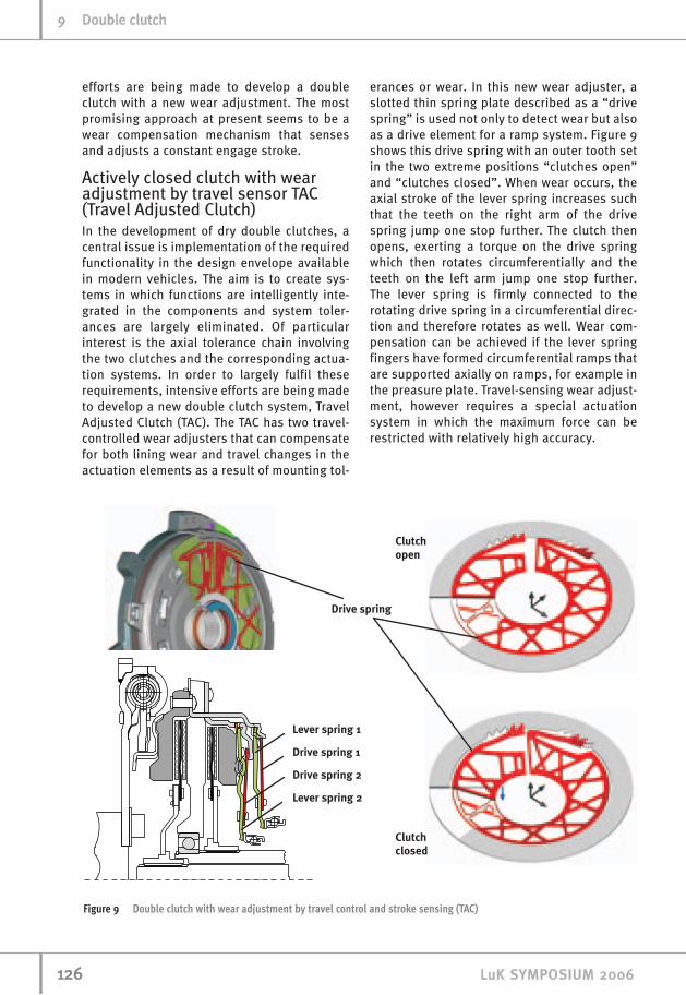
Actively closed clutch with wearadjustment by travel sensor TAC(Travel Adjusted Clutch)In the development of dry double clutches, acentral issue is implementation of the requiredfunctionality in the design envelope availablein modern vehicles. The aim is to create sys-tems in which functions are intelligently inte-grated in the components and system toler-ances are largely eliminated. Of particularinterest is the axial tolerance chain involvingthe two clutches and the corresponding actua-tion systems. In order to largely fulfil theserequirements, intensive efforts are being madeto develop a new double clutch system, TravelAdjusted Clutch (TAC). The TAC has two travel-controlled wear adjusters that can compensatefor both lining wear and travel changes in theactuation elements as a result of mounting tol-
erances or wear. In this new wear adjuster, aslotted thin spring plate described as a “drivespring” is used not only to detect wear but alsoas a drive element for a ramp system. Figure 9shows this drive spring with an outer tooth setin the two extreme positions “clutches open”and “clutches closed”. When wear occurs, theaxial stroke of the lever spring increases suchthat the teeth on the right arm of the drivespring jump one stop further. The clutch thenopens, exerting a torque on the drive springwhich then rotates circumferentially and theteeth on the left arm jump one stop further.The lever spring is firmly connected to therotating drive spring in a circumferential direc-tion and therefore rotates as well. Wear com-pensation can be achieved if the lever springfingers have formed circumferential ramps thatare supported axially on ramps, for example inthe preasure plate. Travel-sensing wear adjust-ment, however requires a special actuationsystem in which the maximum force can berestricted with relatively high accuracy.
112266 LLuuKK SSYYMMPPOOSSIIUUMM 22000066
99 DDoouubbllee cclluuttcchh
Figure 9 Double clutch with wear adjustment by travel control and stroke sensing (TAC)

The wet clutchComplexity and requirementsThe wet double clutches currently in the mar-ket or due to enter the market in the nearfuture are actuated by hydraulic means. Thepressure chambers rotate at the speed of theinternal combustion engine (figure 10). Thisdesign with rotating actuator pistons is gener-ally also used for the clutches in classical con-verter transmissions.
In order to move the hydraulic oil from thehydraulic unit to the pressure chambers, rotarypassages are required that are sealed by slotteddynamic seals allowing leakage. This leakage isone reason why an additional hydraulic powerpack is necessary to hold the clutch at the con-tact point while the engine is not rotating inorder to achieve stop/start functionality. Theclutch can then be closed easily and quicklywhen the engine restarts.
The pressure chambers are sealed by two sealseach on the inside and outside diameter. Inorder to compensate for the influence of the cen-trifugal oil pressure that builds up under rota-
tion, additional oil chambers are included paral-lel to pressure chambers. At least one furtherseal is required per centrifugal oil chamber. Theseals are largely responsible for the hysteresis inclutch actuation.
LuK, however, favours an actuation conceptusing lever springs similar to the state of the artused in dry, actively closed clutches (figure 11).The force is applied by the non-rotating, staticactuation elements via engage bearings to thelever springs rotating at engine speed [5]. Theengage bearings are thus the interface betweenstationary and rotating parts. The lever spring issuspended in the outer disc carrier and actuatesa contact ring that presses the disc assemblytogether. If an actuator fails, the clutch opensautomatically because of the force of leverspring. The external actuation forces are sup-ported directly on a cover bearing, so the crank-shaft is free from axial forces.
This system has the advantage that severalactuation systems are suitable for use. If hydro-static actuation elements or rotary or swivellevers are used in combination with slave cylin-ders, classic hydraulic control systems and elec-trohydraulic power packs can be utilised. Anelectromechanical actuator system can be sim-ply adapted, too.
Actuation systems with an electrically-drivenenergy source independent of the internal com-
112277LLuuKK SSYYMMPPOOSSIIUUMM 22000066
DDoouubbllee cclluuttcchh 99
Figure 10 Wet double clutch with rotating actuatorpistons
Figure 11 Wet lever-actuated double clutch

bustion engine benefit from the leak-free statusof these lever-actuated clutches. This is animportant precondition for hybridisation of thewhole transmission, since not only can theclutches be actuated independent of engine run-ning but there is also no need for permanentpumping of oil to hold the clutch at the operatingpoint.
The lack of seals gives, in comparison with clas-sic wet clutches, very good hysteresis values andsensitive modulation of the clutches (figure 12).Special shaping of the lever spring tonguesallows compensation of centrifugal forces to beachieved simply.
When comparing the lever-actuated wet clutchwith the dry clutch it can be quickly seen that,in terms of requirements and complexity, thewet clutch has no reason to fear comparisonwith the dry clutch (figure 13). It is important toknow here that wet double clutch systemsrequire no wear adjustment mechanism. Oillubrication of the bearings and mechanicalactuator parts saves on sealing work and spe-cial surface treatments can be omitted. Oillubrication also ensures lower losses and hys-teresis.
The relatively large mass of the cast materials indry clutches is also significant. These provide
112288 LLuuKK SSYYMMPPOOSSIIUUMM 22000066
99 DDoouubbllee cclluuttcchh
Figure 12 Hysteresis behaviour of a wet, lever-actuated double clutch
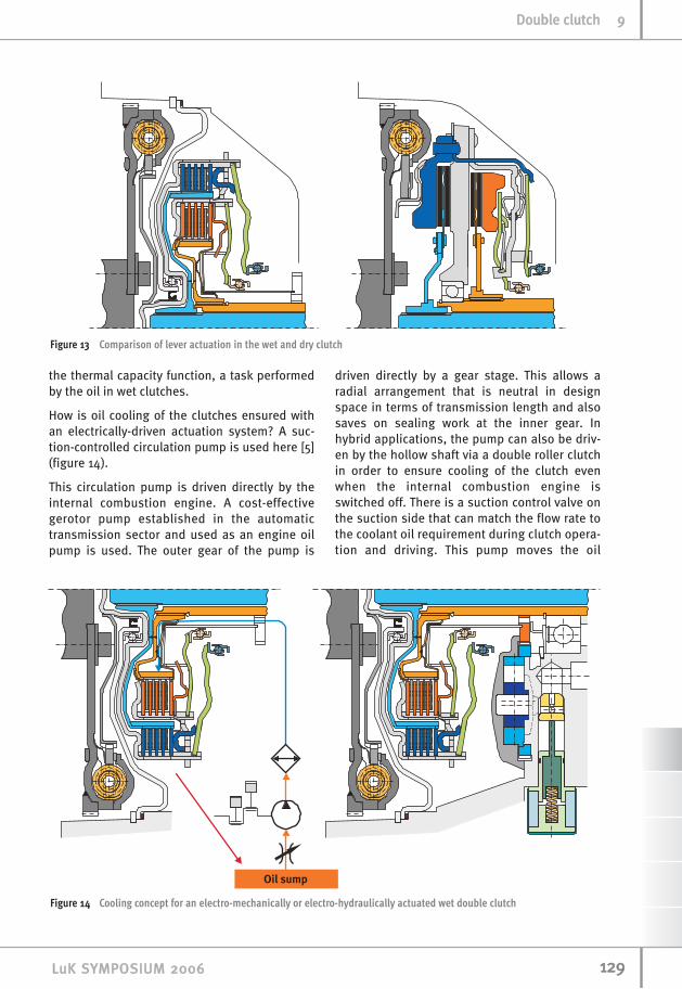
the thermal capacity function, a task performedby the oil in wet clutches.
How is oil cooling of the clutches ensured withan electrically-driven actuation system? A suc-tion-controlled circulation pump is used here [5](figure 14).
This circulation pump is driven directly by theinternal combustion engine. A cost-effectivegerotor pump established in the automatictransmission sector and used as an engine oilpump is used. The outer gear of the pump is
driven directly by a gear stage. This allows aradial arrangement that is neutral in designspace in terms of transmission length and alsosaves on sealing work at the inner gear. Inhybrid applications, the pump can also be driv-en by the hollow shaft via a double roller clutchin order to ensure cooling of the clutch evenwhen the internal combustion engine isswitched off. There is a suction control valve onthe suction side that can match the flow rate tothe coolant oil requirement during clutch opera-tion and driving. This pump moves the oil
112299LLuuKK SSYYMMPPOOSSIIUUMM 22000066
DDoouubbllee cclluuttcchh 99
Figure 14 Cooling concept for an electro-mechanically or electro-hydraulically actuated wet double clutch
Figure 13 Comparison of lever actuation in the wet and dry clutch

through an oil cooler before it is provided to theclutch as a cooled agent.
With the suction control valve in the “cool” posi-tion, the volume flow is determined by the theo-retical displacement rate of the pump. In thisstate, adequate oil flows through the oil coolermaintains the thermal equilibrium of the com-plete transmission during “hill holding” and“uphill creeping”.
In the “drive” position, the oil volume flow canbe greatly reduced. It only prevents burning ofthe open clutch linings and ensures cooling ofthe actuated clutch under microslippage control.In this operating condition approx. 2…3 l/min ofoil flow through the oil cooler. This oil quantitygives sufficient cooling for the small additionalpump losses which compares to a manualgearshift of approx. 1 kW during rapid travel andhence maintains a stable thermal equilibrium inthe complete transmission.
Since the pump is used only for cooling andlubrication of the clutch and only pressurelosses in the oil cooler and ducts must beconsidered, pump pressures significantlybelow 1 bar occur in the range relevant to con-sumption and maximum pressures below 5 bar during clutch cooling and low oil tem-peratures.
These low pressures allow a technological leapin selecting the material for the pump, whichcan now be made almost entirely of plastic.The suction control valve can simply be inte-grated in the pump housing. Due to the use of plastic, no machining of parts is requiredand a significant cost benefit can be achieved(figure 15).
The combination of a lever-actuated doublewet clutch and a simple, robust cooling con-cept significantly reduces the complexity ofthe wet clutch without compromises on func-tionality.
LuK is also working on cooling concepts usinga ring-shaped oil cooler and the kinetic energyof the rotating oil emerging from the clutch tocreate coolant oil circulation (figure 16). A jetpump ensures permanent exchange betweenthe circulating oil and the oil sump. This alsoallows complete utilisation of the oil sump as aheat sink in situations with high energy inputs.
These measures allow simplified feed layout,use of a more economical cooler and evenelimination of the already economical plasticpump.
Fuel consumptionOne of the most important issues in the develop-ment of double clutch transmissions is utilisa-tion of the high transmission efficiency and theassociated favourable fuel consumption of thevehicle.
If one analyses the fuel consumption data pro-vided by automotive manufacturers, it is appar-ent that the high efficiency of the mechanicaltransmission side does not automatically givelow consumption over the cycle (figure 17). Indiesel vehicles with low and moderate power rat-ings in particular, the double clutch transmis-sion still cannot use its advantages. Even theCVT transmissions, which are little disadvan-taged in the partial load range in relation to vari-ator efficiency, give some better or comparableresults. At present the double clutch transmis-sion is only convincing at high powered gasengines.
Why is this the case? The CVT transmissiondevelopment engineers have compensated the small disadvantages at variator side byapplication of dual flow pumps and jet pumpsas well as a hydraulic concept optimised interms of low operating pressures and pumpsize.
113300 LLuuKK SSYYMMPPOOSSIIUUMM 22000066
99 DDoouubbllee cclluuttcchh
Figure 15 Plastic pump

The high efficiency of the mechanical transmis-sion side of double clutch transmissions, thelow mass moments of inertia of wet clutches,the feasibility of oil splash lubrication of thetransmission and a suitable preselection strat-egy to eliminate drag torques in the disen-gaged clutch already give good conditions forexploiting further system advantages andeliminating disadvantages in comparison toother transmission concepts and also in com-parison to double clutch transmission with dryclutches.
The greatest portion of losses are caused by thehydraulic pump which must on the one handprovide large quantities of coolant oil to coolthe clutches and on the other hand create oper-ating pressure to close the clutches. This con-flict of interests leads to comparatively largepump sizes with correspondingly higher sys-tem pressures in the systems currently on themarket.
Benchmarking studies have shown that whentravelling at a constant 50 km/h, the pump loss-es influenced the fuel consumption of a 250 Nmdiesel minivan by approx. 7 %. In the NEDC mixedcycle, this value was 7 … 8 %.
There is enormous potential for improvementhere. The lever-actuated clutch presented, incombination with an electromechanical or elec-trohydraulic actuation system and a circulationpump exclusively for coolant oil gives good con-ditions for such improvement.
The electrical losses in the electro-hydraulicpower pack or the electric motors in themechanical actuation system and electricallycontrolled suction control valve are of the sameorder as the losses in the numerous switching,PWM and proportional solenoids in the classicalhydraulic control unit. It is thus permissible toconcentrate on the comparison of the purepump losses.
113311LLuuKK SSYYMMPPOOSSIIUUMM 22000066
DDoouubbllee cclluuttcchh 99
Figure 16 New cooling concept
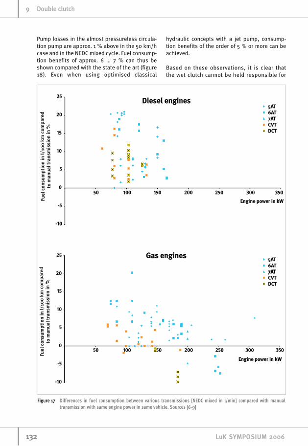
Pump losses in the almost pressureless circula-tion pump are approx. 1 % above in the 50 km/hcase and in the NEDC mixed cycle. Fuel consump-tion benefits of approx. 6 … 7 % can thus beshown compared with the state of the art (figure18). Even when using optimised classical
hydraulic concepts with a jet pump, consump-tion benefits of the order of 5 % or more can beachieved.
Based on these observations, it is clear thatthe wet clutch cannot be held responsible for
113322 LLuuKK SSYYMMPPOOSSIIUUMM 22000066
99 DDoouubbllee cclluuttcchh
Figure 17 Differences in fuel consumption between various transmissions [NEDC mixed in l/min] compared with manualtransmission with same engine power in same vehicle. Sources [6-9]

higher fuel consumption; the actuation andcooling concept plays the decisive role. If loss-es here are actively reduced and advantagessuch as the lower inertia forces and splash oillubrication are exploited, consumption valuesmove very much closer to those of dry sys-tems.
The use of electric actuators for clutch actua-tion and gearshift gives good conditions forthe hybridisation capacity of double clutchtransmissions. The extra cost of an additionalpower pack in classical hydraulic controlsystems to ensure prefilling of the clutcheswhile the internal combustion engine isswitched off can be saved by using electricactuators independent of the internal combus-tion engine. As a result, this actuation conceptin combination with a lever-actuated wet start-up clutch is well equipped for the demands ofthe future.
ConclusionOnce boundary conditions such as torque capac-ity, axial design envelope, fuel consumption,life, ability to handle high energy situations andcosts are taken into consideration, wet and dry
double clutches have their specific advantagesand disadvantages that, depending on theweighting and customer philosophy, may lead todifferent decisions.
Whether the double clutch transmission willmake a major breakthrough or remain a nicheproduct will be determined by market forces.Double clutch transmissions currently stillhave some potential in terms of fuel consump-tion and costs in comparison with CVTs and thebest stepped automatic transmissions [6-10].Attention must also be paid to the issue ofhybridisation in all automatic transmissionconcepts.
Due to simple principles for wear adjustmentand greater robustness in high energy situa-tions, dry double clutches have also become aserious alternative for moderate to high enginetorques.
Much of the dry clutches technology was carriedover to the wet double clutch systems. Now it ispossible to draw together the advantages ofelectrically driven actuators combined with a cir-culation pump, with the advantages in highenergy situations and for the design envelope,especially at high power levels.
113333LLuuKK SSYYMMPPOOSSIIUUMM 22000066
DDoouubbllee cclluuttcchh 99
Figure 18 As Figure 17 for diesel applications, additional data for three selected vehicles for dry and wet double clutch trans-missions with LuK electric actuators
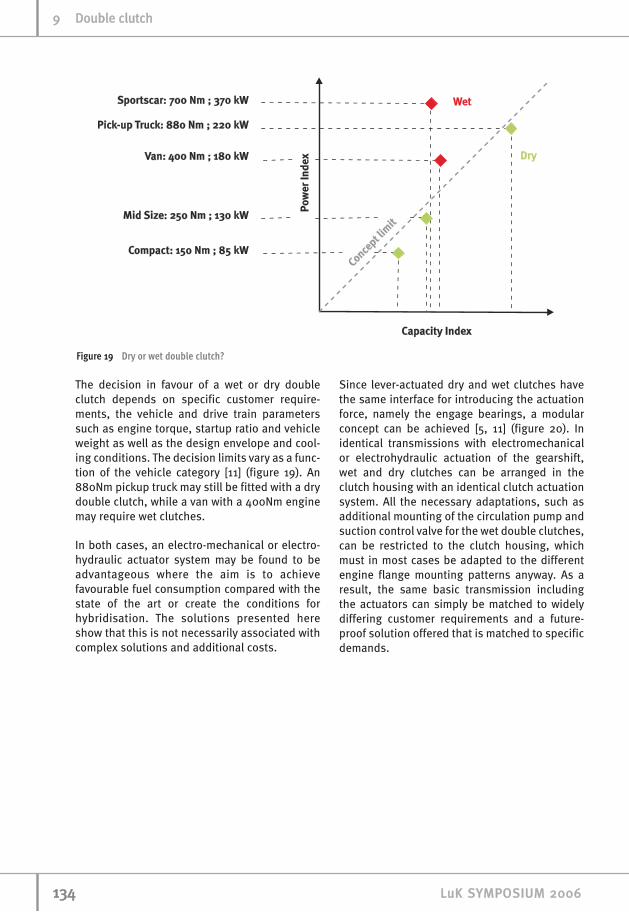
The decision in favour of a wet or dry doubleclutch depends on specific customer require-ments, the vehicle and drive train parameterssuch as engine torque, startup ratio and vehicleweight as well as the design envelope and cool-ing conditions. The decision limits vary as a func-tion of the vehicle category [11] (figure 19). An880Nm pickup truck may still be fitted with a drydouble clutch, while a van with a 400Nm enginemay require wet clutches.
In both cases, an electro-mechanical or electro-hydraulic actuator system may be found to beadvantageous where the aim is to achievefavourable fuel consumption compared with thestate of the art or create the conditions forhybridisation. The solutions presented hereshow that this is not necessarily associated withcomplex solutions and additional costs.
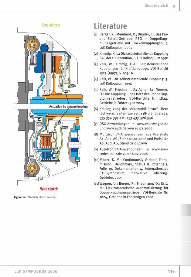
Since lever-actuated dry and wet clutches havethe same interface for introducing the actuationforce, namely the engage bearings, a modularconcept can be achieved [5, 11] (figure 20). Inidentical transmissions with electromechanicalor electrohydraulic actuation of the gearshift,wet and dry clutches can be arranged in theclutch housing with an identical clutch actuationsystem. All the necessary adaptations, such asadditional mounting of the circulation pump andsuction control valve for the wet double clutches,can be restricted to the clutch housing, whichmust in most cases be adapted to the differentengine flange mounting patterns anyway. As aresult, the same basic transmission includingthe actuators can simply be matched to widelydiffering customer requirements and a future-proof solution offered that is matched to specificdemands.
113344 LLuuKK SSYYMMPPOOSSIIUUMM 22000066
99 DDoouubbllee cclluuttcchh
Figure 19 Dry or wet double clutch?
Literature[1] Berger, R.; Meinhard, R.; Bünder, C.: Das Par-
allel-Schalt-Getriebe PSG – Doppelkup-plungsgetriebe mit Trockenkupplungen, 7.LuK Kolloquium 2002
[2] Kimmig, K.-L.: Die selbsteinstellende KupplungSAC der 2. Generation, 6. LuK Kolloquium 1998
[3] Reik, W.; Kimmig, K.-L.: SelbsteinstellendeKupplungen für Kraftfahrzeuge, VDI Bericht1323 (1997), S. 105-116
[4] Reik, W.: Die selbsteinstellende Kupplung, 5.LuK Kolloquium 1994
[5] Reik, W.; Friedmann,O.; Agner, I.; Werner,O.: Die Kupplung – das Herz des Doppelkup-plungsgetriebes, VDI-Berichte Nr. 1824,Getriebe in Fahrzeugen 2004
[6] Katalog 2005 der “Automobil Revue”, Bern(Schweiz), Seiten 121-135, 138-152, 232-243,335-357, 397-411, 433-437, 526-546
[7] DSG-Anwendungen in www.volkswagen.deund www.audi.de vom 16.02.2006
[8] Multitronic®-Anwendungen aus PreislisteA4, Audi AG, Stand 01.01.2006 und PreislisteA6, Audi AG, Stand 01.01.2006
[9] Autotronic®-Anwendungen in www.mer-cedes-benz.de vom 16.02.2006
[10]Mäder, K. M.: Continuously Variable Trans-mission: Benchmark, Status & Potentials,Folie 19, Dokumentation 4. InternationalesCTI-Symposium, Innovative Fahrzeug-Getriebe, 2005
[11] Wagner, U.; Berger, R.; Friedmann, O.; Esly,N.: Elektromotorische Automatisierung fürDoppelkupplungsgetriebe, VDI-Berichte Nr.1824, Getriebe in Fahrzeugen 2004
113355LLuuKK SSYYMMPPOOSSIIUUMM 22000066
DDoouubbllee cclluuttcchh 99
Figure 20 Modular clutch concept