double wishbone suspension system - iaeme.com · the suspension consists of spring, dampers and...
TRANSCRIPT
http://www.iaeme.com/IJMET/index.asp 249 [email protected]
International Journal of Mechanical Engineering and Technology (IJMET) Volume 8, Issue 5, May 2017, pp. 249–264 Article ID: IJMET_08_05_027
Available online at http:// http://www.iaeme.com/ijmet/issues.asp?JType=IJMET&VType=8&IType=5
ISSN Print: 0976-6340 and ISSN Online: 0976-6359
© IAEME Publication Scopus Indexed
DOUBLE WISHBONE SUSPENSION SYSTEM
B. Rohith Raju
Department of Mechanical Engineering, K.L University, Green Fields, India
K.P.V.S. Raja Rao
Department of Mechanical Engineering, K.L University, Green Fields, India
V.V Suraj
Department of Mechanical Engineering, K.L University, Green Fields, India
P. Ratna Prasad
Department of Mechanical Engineering, K.L University, Green Fields, India
ABSTRACT
Suspension system plays a crucial role in the handling of the vehicle. It helps the driver
to maneuver the vehicle. The main function of suspension is to make sure that the driver
feels comfortable while riding the car and the forces are damped to prevent chassis from
getting damaged. Suspension helps to keep the tires in contact with ground when they
encounter any bump on their way. Thus suspension is used in automobiles. This paper
mainly concentrates on the design of the suspension for a formula car, modifying the
mounting points, analyzing of the forces which are to be damped by the suspension.
Key words: Pushrods, Rocker Arms, Sprung Masses, Unsprung Masses
Cite this Article: B. Rohith Raju, K.P.V.S. Raja Rao, V.V Suraj and P. Ratna Prasad,
Double Wishbone Suspension System, International Journal of Mechanical Engineering
and Technology, 8(5), 2017, pp. 249-264.
http:// http://www.iaeme.com/ijmet/issues.asp?JType=IJMET&VType=8&IType=5
1. INTRODUCTION
In any automotive system, suspension plays a crucial role in providing comfort to the people in
the automobile and protects the important parts from the shocks or the forces that act when it
encounters an obstacle on its way. Suspension is a very basic system and can provide comfort to
the passenger in many ways. Having sufficient pressure of air in the tires of the automobile,
cushioning of the seats, padding of few components such as steering wheel provides certain
resistance to the shocks that are generated. But this is not close enough to a considerable extent of
Double Wishbone Suspension System
http://www.iaeme.com/IJMET/index.asp 250 [email protected]
damping the shock generated. Hence other components such as springs are used to damp the
majority portion of the shocks generated.
The suspension consists of spring, dampers and links that connect the tires to the springs and
dampers. When the tire hits a bump or an obstacle on road, it would be subjected to some forces,
which would get transferred to the chassis if they are not damped. These forces would cause chassis
a permanent damage resulting in the breakage of the metal. The loads transferred strictly depend
on the sprung and unsprung mass of the vehicle. The larger the ratio of sprung mass to that of the
unsprung mass, the more stable the vehicle would be.
The main functions of the suspension system are as follows:
1. It helps to keep the tires in contact with the road.
2. Prevents damage to the chassis if any sudden forces are encountered.
3. Provides comfort to the driver
4. Supports the weight of the vehicle.
2. SELECTION OF THE SUSPENSION SYSTEM
Since the suspension we are about to design is used for formula1 cars, out of many suspensions,
we choose double wishbone suspension system. The below are the following reasons for which
double wishbone suspension system is selected:
1. It provides a less ride height which is an essential feature for a formula car.
2. Flexibility ( in terms of wheel alignment i.e., setting of camber angle)
3. Less cost
4. Load bearing capacity of the system.
5. Availability of components in local market.
3. MATERIAL SELECTION
The most important part in designing and manufacturing of any component is the selection of the
material. As this car is fabricated as per the rules mentioned in the rule book, we must follow few
regulations laid by SAE. After the designing of the suspension system (geometry) the material
selection is done. Few factors that are to be considered in the selection of material are as follows:
1. Availability
2. Cost of the material
3. Density of the material
4. Yield strength of the material
5. Bending strength of the material
6. Weight of the material etc.
In the rule book it is mentioned that the material used must be LESS WEIGHT and MORE
STRONG. Hence chromoly can be selected as the best material for use. Each and every part of the
suspension system is made up of different materials. The following gives the details of the material
used in different components of the suspension system:
B. Rohith Raju, K.P.V.S. Raja Rao, V.V Suraj and P. Ratna Prasad
http://www.iaeme.com/IJMET/index.asp 251 [email protected]
1. The rocker arms are made up of aluminum.
2. Push rods are made up of mild steel
3. Springs are made up of chrome steel
4. Caps are made up of aluminum
5. Adjustable column is made up of aluminum
Few important properties of different materials available in market are mentioned in the table
1.1:
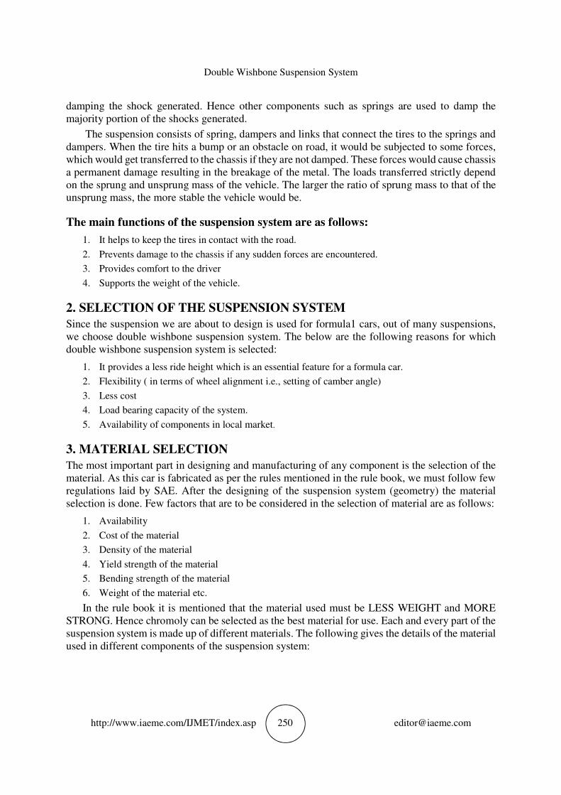
Table 1.1 parameters of different materials
Parameters Chromoly 4130 1018 steel T6 6061 aluminum
Yield strength(ksi) 63.1 53.7 40
Bending stiffness(lb x in2) 829898.26 829898.26 279430
Bending strength(lb x in) 3526.369057 3001.07 2237.13
Density(g/cm3) 7.85 7.87 2.70
Cost per feet 162Rs/ft 60Rs/ft 200Rs/ft
The table 1.1 is made by considering the material dimension of 1 inch X 0.095 inch.
4. RATING OF THE MATERIAL
Generally a rating is given to any material depending on various parameters for the selected
material. The overall rating is for 25 points. The above 3 materials are rated in the table 1.2:
Table 1.2 rating of different materials
Parameters Chromoly
4130
1018
steel
T6 6061
Aluminum
Yield strength 5 4 3
Manufacturability 5 5 4
Bending strength 5 4 2
weight 3 3 5
cost 3 5 2
Total 21 20 15
As rated in the table 1.2, chromoly and 1018 steel are almost close, but with a minor difference
in bending strength. Hence, we consider chromoly 4130 for the fabrication of A-arms of the
suspension system.
The next important factor which we need to consider while fabricating is the selection of the
thickness of the material. The following graphs show different factors for different thickness of
the materials:
Double Wishbone Suspension System
http://www.iaeme.com/IJMET/index.asp 252 [email protected]
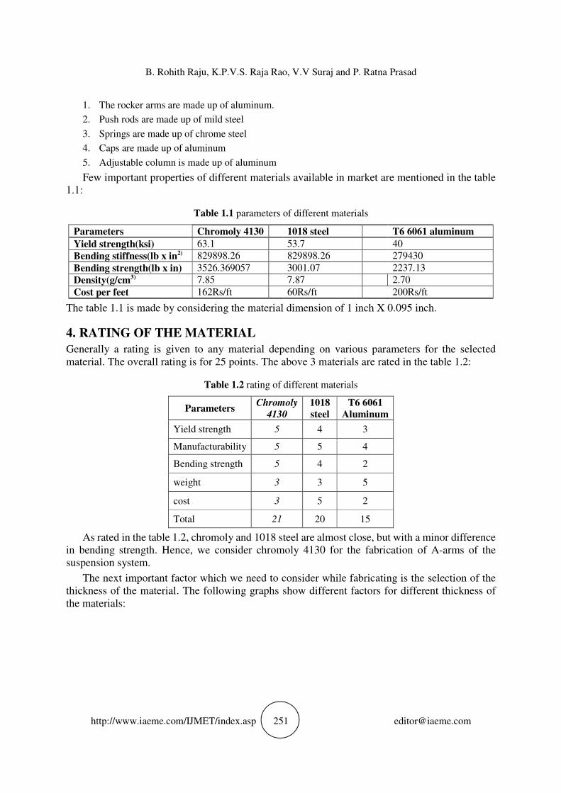
Figure 1.1 Graph showing bending stiffness vs. thickness
The above graph fig: 1.1 shows the bending stiffness of chromoly 4130 at different cross
sections and at various thicknesses.
Figure 1.2 graph showing weight vs. thickness
The above graph fig: 1.2 shows density of chromoly 4130 at variable thickness and at various
diameters.
Figure 1.3 graph showing bending strength vs. thickness
450000
950000
1450000
1950000
2450000
2950000
3450000
3950000
Bending Stiffness(lb X in2) vs
Thickness(in)
dia1
Dia1.125
Dia1.25
Dia 1.375
Dia 1.5
Reference
0
0.5
1
1.5
2
0.058 0.065 0.083 0.095 0.12 0.125
Weight(lb/ft) vs thickness(in)
Dia1
Dia1
.125
0
2000
4000
6000
8000
10000
12000
Bending strength(lb*in) vs Thickness(in)
Dia1
Dia1.125
Dia1.25
Dia1.375
Dia1.5
reference
B. Rohith Raju, K.P.V.S. Raja Rao, V.V Suraj and P. Ratna Prasad
http://www.iaeme.com/IJMET/index.asp 253 [email protected]
The above graph Fig: 1.3 shows the bending strength of the material chromoly 4130 at different
thickness and at different diameters.
5. ANALYSING THE MASSES
After the selection of materials the next important task is the analyzing the weights on the
suspension components. The masses in the system can be divided into 2 types. They are:
• Sprung masses and
• Unsprung masses.
Sprung masses: sprung masses can be defined as the mass of the components of the body that
are supported by the springs of the system.
Unsprung masses: unsprung masses are the masses that move with the body (i.e. while
travelling over bumps or any irregular surface). Generally these include the weights of tires, hubs,
uprights etc.
Generally the components that are considered to be on the sprung masses are protected from
sudden shocks and loads. These are considered not to take any shocks or minimum shocks.
Components like frame of the body, drive train and its components etc. can be considered as sprung
masses.
The sprung masses are more important when it comes to stability. As the sprung mass
increases, the stability of the vehicle increases. Hence when we try to divide the masses, we almost
try to maximize the sprung mass so that the vehicle would be as stable as possible.
For the suspension system we are about to create, the masses are as follows:
Sprung Mass front = 96kg
Sprung Mass rear=144kg
These masses include the masses of all the components that are supported by the springs.
6. DESIGN OF THE COMPONENTS
After deciding the sprung and unsprung masses, the next task comes to the design of the
components. The designing of the components is done by following few rules and regulation that
are described in the rule book.
Among all the rules that are mentioned in the rule book, the important rule that we consider in
designing is that there must be a jounce and rejounce of spring that must be maximum of 1 inch.
Few other rule about ground clearance, wheel base etc., are considered.
The main components of the suspension are:
• A-Arms
• Push rods
• Rocker arms
• Springs with dampers
As we all know the mechanism, if the automobile faces any sudden load (bump on the road),
then the load is transferred to A-arms from tires, then to push rods, to rocker arms and finally to
the damper where the shock will be damped. The design of all the components should be in such
a way that they take up the loads without getting failed.
Double Wishbone Suspension System
http://www.iaeme.com/IJMET/index.asp 254 [email protected]
We use solid works software, for the modeling of the components. Solid works is one of the
famous modeling software that is used in the designing process.
The designed components of the suspension system are as follows:
6.1. A-Arms
A- Arms can be termed as the starting part of the suspension system, from where the load
transferring takes place. These components hold the wheels of the automobile and are attached to
the chassis. When the automobile is subjected to any sudden obstacles, these will the first
component which is used to transfer the shock to the damping system.
The following are the designed components of suspension system:
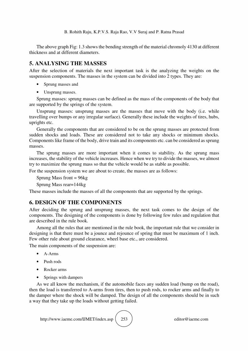
6.2. Spring
Spring is one of the main components in the suspension system. Without these, the suspension will
be incomplete. Springs take the forces that are generated and damp them. The spring material is
made up of chrome silicon. The following are the details of the springs:
Spring Material=Chrome Silicon
Spring Stiffness=30N/mm^2
Spring wire diameter (d) =4.4mm
Spring outer diameter (D) =65mm
Pitch=12mm
Total Length I to I=11inch
Number of Active coils=8
Figure 3.0 spring
The Fig: 3.0 represent a model of sprig which is used in the suspension system designed.
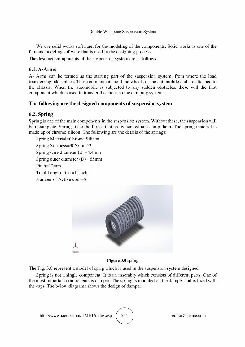
Spring is not a single component. It is an assembly which consists of different parts. One of
the most important components is damper. The spring is mounted on the damper and is fixed with
the caps. The below diagrams shows the design of damper.
B. Rohith Raju, K.P.V.S. Raja Rao, V.V Suraj and P. Ratna Prasad
http://www.iaeme.com/IJMET/index.asp 255 [email protected]
Figure 3.1
Figure 3.2
Figure 3.3
Fig 3.1, Fig 3.2, Fig 3.3, describes the components which are used for the mounting of springs
and shock absorbers.
Double Wishbone Suspension System
http://www.iaeme.com/IJMET/index.asp 256 [email protected]
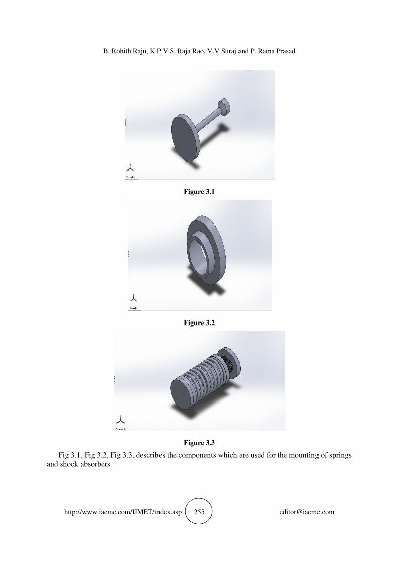
Here the damper travel is considered to be 5cms.
Figure 3.4 shock absorber
Fig: 3.4 represent a shock absorber.
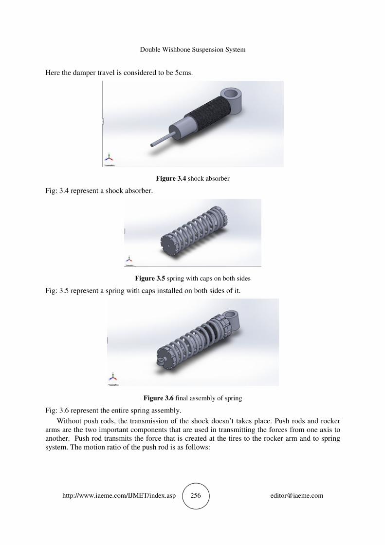
Figure 3.5 spring with caps on both sides
Fig: 3.5 represent a spring with caps installed on both sides of it.
Figure 3.6 final assembly of spring
Fig: 3.6 represent the entire spring assembly.
Without push rods, the transmission of the shock doesn’t takes place. Push rods and rocker
arms are the two important components that are used in transmitting the forces from one axis to
another. Push rod transmits the force that is created at the tires to the rocker arm and to spring
system. The motion ratio of the push rod is as follows:
B. Rohith Raju, K.P.V.S. Raja Rao, V.V Suraj and P. Ratna Prasad
http://www.iaeme.com/IJMET/index.asp 257 [email protected]
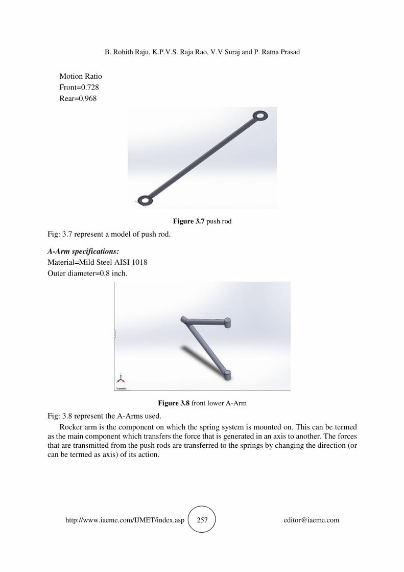
Motion Ratio
Front=0.728
Rear=0.968
Figure 3.7 push rod
Fig: 3.7 represent a model of push rod.
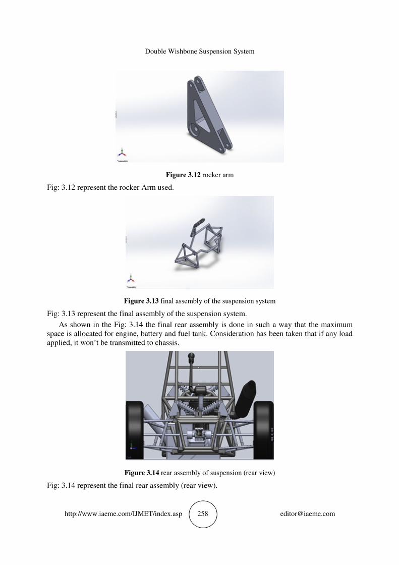
A-Arm specifications:
Material=Mild Steel AISI 1018
Outer diameter=0.8 inch.
Figure 3.8 front lower A-Arm
Fig: 3.8 represent the A-Arms used.
Rocker arm is the component on which the spring system is mounted on. This can be termed
as the main component which transfers the force that is generated in an axis to another. The forces
that are transmitted from the push rods are transferred to the springs by changing the direction (or
can be termed as axis) of its action.
Double Wishbone Suspension System
http://www.iaeme.com/IJMET/index.asp 258 [email protected]
Figure 3.12 rocker arm
Fig: 3.12 represent the rocker Arm used.
Figure 3.13 final assembly of the suspension system
Fig: 3.13 represent the final assembly of the suspension system.
As shown in the Fig: 3.14 the final rear assembly is done in such a way that the maximum
space is allocated for engine, battery and fuel tank. Consideration has been taken that if any load
applied, it won’t be transmitted to chassis.
Figure 3.14 rear assembly of suspension (rear view)
Fig: 3.14 represent the final rear assembly (rear view).
B. Rohith Raju, K.P.V.S. Raja Rao, V.V Suraj and P. Ratna Prasad
http://www.iaeme.com/IJMET/index.asp 259 [email protected]
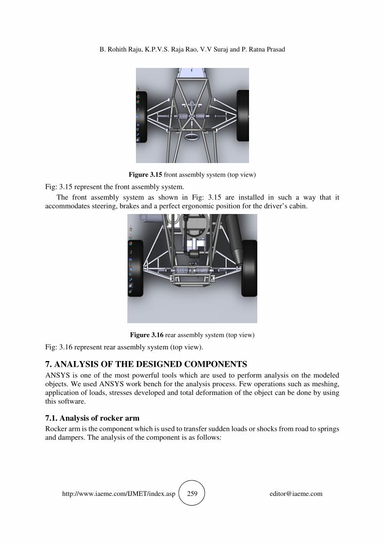
Figure 3.15 front assembly system (top view)
Fig: 3.15 represent the front assembly system.
The front assembly system as shown in Fig: 3.15 are installed in such a way that it
accommodates steering, brakes and a perfect ergonomic position for the driver’s cabin.
Figure 3.16 rear assembly system (top view)
Fig: 3.16 represent rear assembly system (top view).
7. ANALYSIS OF THE DESIGNED COMPONENTS
ANSYS is one of the most powerful tools which are used to perform analysis on the modeled
objects. We used ANSYS work bench for the analysis process. Few operations such as meshing,
application of loads, stresses developed and total deformation of the object can be done by using
this software.
7.1. Analysis of rocker arm
Rocker arm is the component which is used to transfer sudden loads or shocks from road to springs
and dampers. The analysis of the component is as follows:
Double Wishbone Suspension System
http://www.iaeme.com/IJMET/index.asp 260 [email protected]
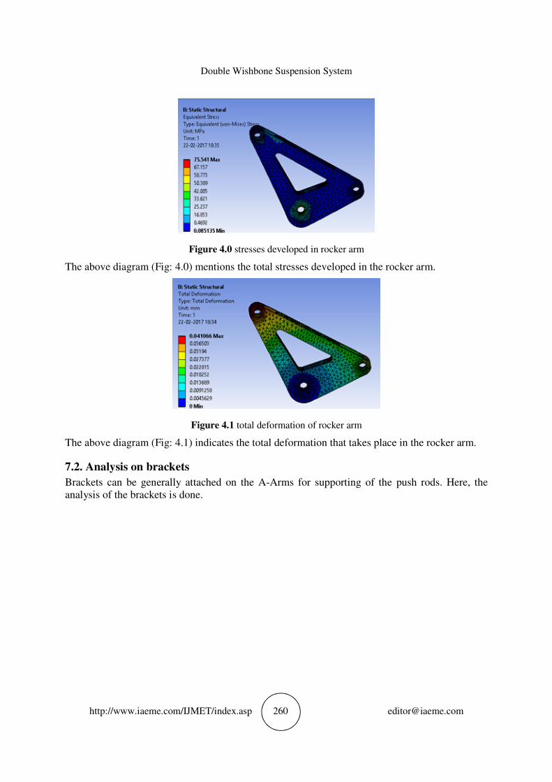
Figure 4.0 stresses developed in rocker arm
The above diagram (Fig: 4.0) mentions the total stresses developed in the rocker arm.
Figure 4.1 total deformation of rocker arm
The above diagram (Fig: 4.1) indicates the total deformation that takes place in the rocker arm.
7.2. Analysis on brackets
Brackets can be generally attached on the A-Arms for supporting of the push rods. Here, the
analysis of the brackets is done.
B. Rohith Raju, K.P.V.S. Raja Rao, V.V Suraj and P. Ratna Prasad
http://www.iaeme.com/IJMET/index.asp 261 [email protected]
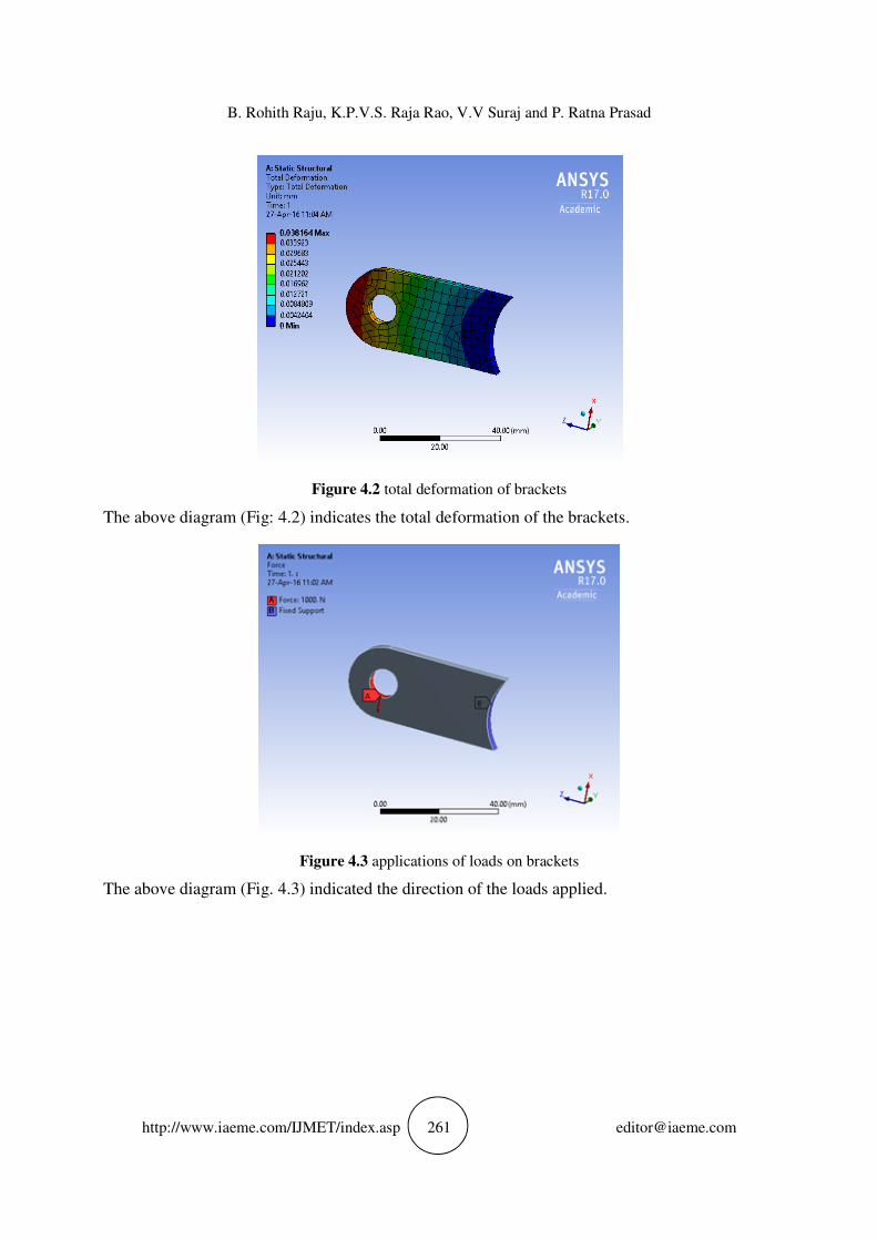
Figure 4.2 total deformation of brackets
The above diagram (Fig: 4.2) indicates the total deformation of the brackets.
Figure 4.3 applications of loads on brackets
The above diagram (Fig. 4.3) indicated the direction of the loads applied.
Double Wishbone Suspension System
http://www.iaeme.com/IJMET/index.asp 262 [email protected]
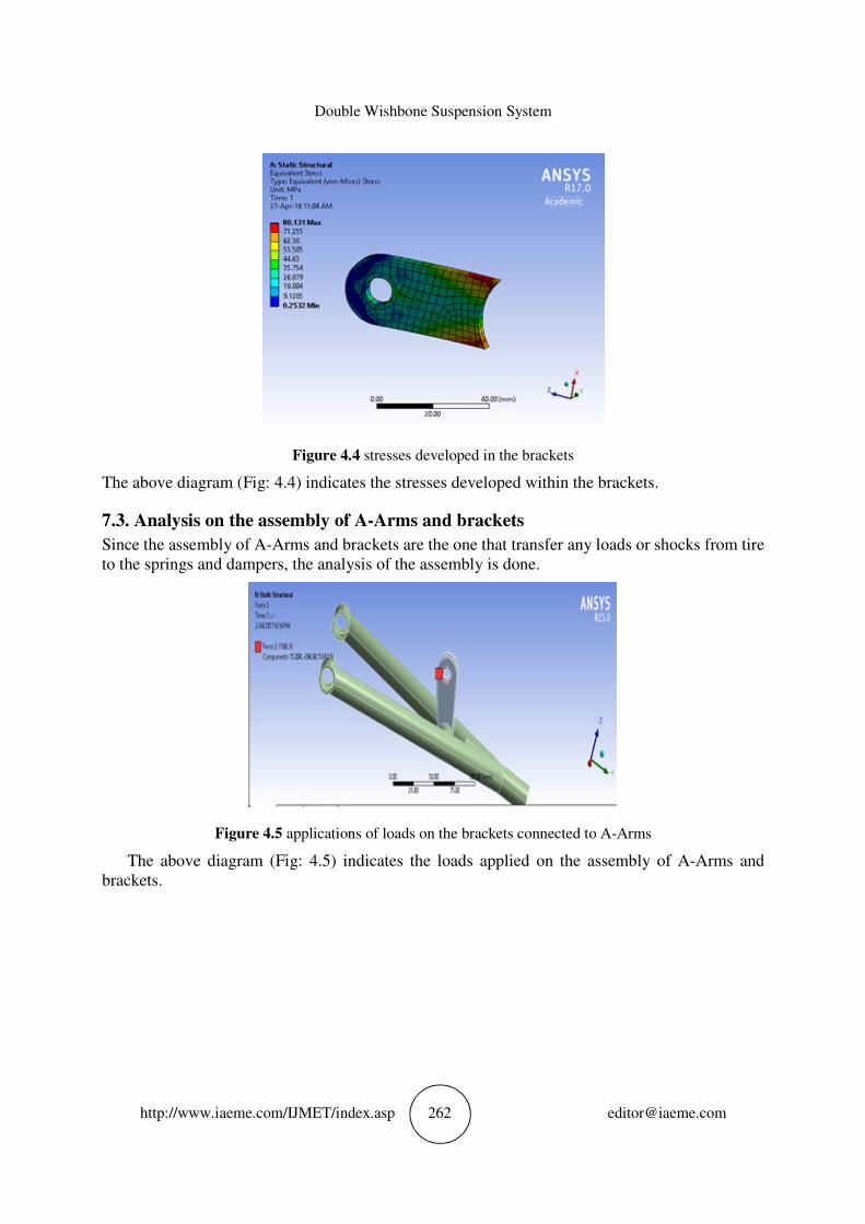
Figure 4.4 stresses developed in the brackets
The above diagram (Fig: 4.4) indicates the stresses developed within the brackets.
7.3. Analysis on the assembly of A-Arms and brackets
Since the assembly of A-Arms and brackets are the one that transfer any loads or shocks from tire
to the springs and dampers, the analysis of the assembly is done.
Figure 4.5 applications of loads on the brackets connected to A-Arms
The above diagram (Fig: 4.5) indicates the loads applied on the assembly of A-Arms and
brackets.
B. Rohith Raju, K.P.V.S. Raja Rao, V.V Suraj and P. Ratna Prasad
http://www.iaeme.com/IJMET/index.asp 263 [email protected]
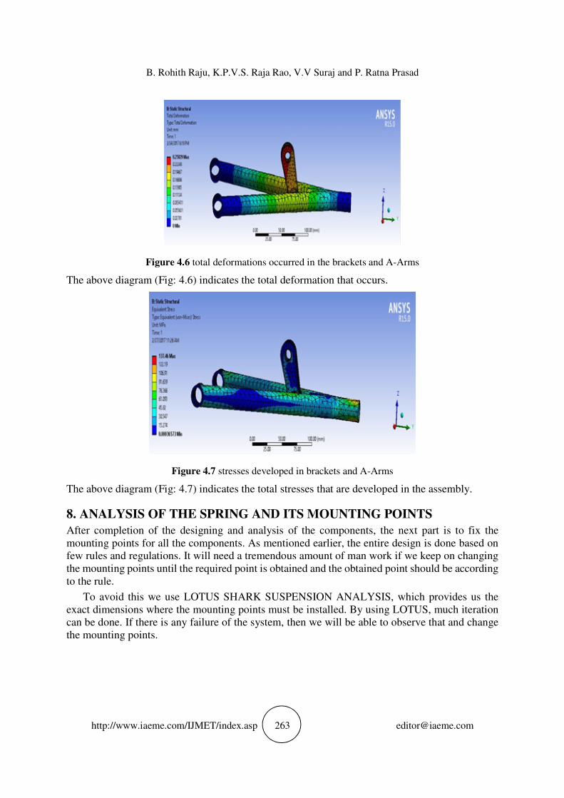
Figure 4.6 total deformations occurred in the brackets and A-Arms
The above diagram (Fig: 4.6) indicates the total deformation that occurs.
Figure 4.7 stresses developed in brackets and A-Arms
The above diagram (Fig: 4.7) indicates the total stresses that are developed in the assembly.
8. ANALYSIS OF THE SPRING AND ITS MOUNTING POINTS
After completion of the designing and analysis of the components, the next part is to fix the
mounting points for all the components. As mentioned earlier, the entire design is done based on
few rules and regulations. It will need a tremendous amount of man work if we keep on changing
the mounting points until the required point is obtained and the obtained point should be according
to the rule.
To avoid this we use LOTUS SHARK SUSPENSION ANALYSIS, which provides us the
exact dimensions where the mounting points must be installed. By using LOTUS, much iteration
can be done. If there is any failure of the system, then we will be able to observe that and change
the mounting points.
Double Wishbone Suspension System
http://www.iaeme.com/IJMET/index.asp 264 [email protected]
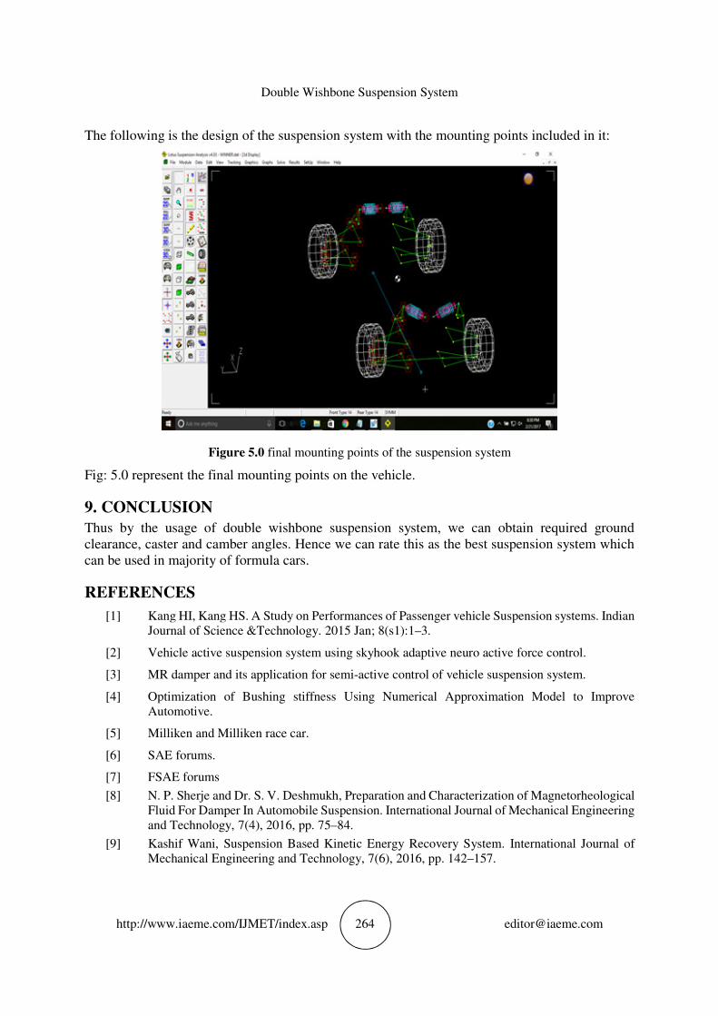
The following is the design of the suspension system with the mounting points included in it:
Figure 5.0 final mounting points of the suspension system
Fig: 5.0 represent the final mounting points on the vehicle.
9. CONCLUSION
Thus by the usage of double wishbone suspension system, we can obtain required ground
clearance, caster and camber angles. Hence we can rate this as the best suspension system which
can be used in majority of formula cars.
REFERENCES
[1] Kang HI, Kang HS. A Study on Performances of Passenger vehicle Suspension systems. Indian
Journal of Science &Technology. 2015 Jan; 8(s1):1–3.
[2] Vehicle active suspension system using skyhook adaptive neuro active force control.
[3] MR damper and its application for semi-active control of vehicle suspension system.
[4] Optimization of Bushing stiffness Using Numerical Approximation Model to Improve
Automotive.
[5] Milliken and Milliken race car.
[6] SAE forums.
[7] FSAE forums
[8] N. P. Sherje and Dr. S. V. Deshmukh, Preparation and Characterization of Magnetorheological
Fluid For Damper In Automobile Suspension. International Journal of Mechanical Engineering
and Technology, 7(4), 2016, pp. 75–84.
[9] Kashif Wani, Suspension Based Kinetic Energy Recovery System. International Journal of
Mechanical Engineering and Technology, 7(6), 2016, pp. 142–157.