download (1231kb) - northumbria research link
TRANSCRIPT
Northumbria Research Link
Citation: Perez Soler, Joaquin, Morant, Maria, Llorente, Roberto and Marti, Javier (2009)Joint distribution of polarization-multiplexed UWB and WiMAX radio in PON. Journal ofLightwave Technology, 27 (12). pp. 1912-1919. ISSN 0733-8724
Published by: IEEE
URL: http://dx.doi.org/10.1109/JLT.2009.2022342<http://dx.doi.org/10.1109/JLT.2009.2022342>
This version was downloaded from Northumbria Research Link:http://nrl.northumbria.ac.uk/id/eprint/3238/
Northumbria University has developed Northumbria Research Link (NRL) to enable usersto access the University’s research output. Copyright © and moral rights for items onNRL are retained by the individual author(s) and/or other copyright owners. Single copiesof full items can be reproduced, displayed or performed, and given to third parties in anyformat or medium for personal research or study, educational, or not-for-profit purposeswithout prior permission or charge, provided the authors, title and full bibliographicdetails are given, as well as a hyperlink and/or URL to the original metadata page. Thecontent must not be changed in any way. Full items must not be sold commercially in anyformat or medium without formal permission of the copyright holder. The full policy isavailable online: http://nrl.northumbria.ac.uk/policies.html
This document may differ from the final, published version of the research and has beenmade available online in accordance with publisher policies. To read and/or cite from thepublished version of the research, please visit the publisher’s website (a subscriptionmay be required.)
1912 JOURNAL OF LIGHTWAVE TECHNOLOGY, VOL. 27, NO. 12, JUNE 15, 2009
Joint Distribution of Polarization-Multiplexed UWBand WiMAX Radio in PON
Joaquin Perez, Student Member, IEEE, Maria Morant, Student Member, IEEE, Roberto Llorente, Member, IEEE,and Javier Martí, Member, IEEE
Abstract—In this paper, the feasibility of the joint distributionof ultra-wideband (UWB) and WIMAX wireless using polar-ization multiplexing as a coexistence technique is proposed andexperimentally demonstrated within the framework of passiveoptical networks (PON). Four single- and orthogonal-polarizationmultiplexing schemes are studied targeting to reduce the mutualinterference when UWB and WiMAX are distributed jointlythrough standard single-mode fiber (SSMF) without transmissionimpairments compensation techniques and amplification. Exper-imental results indicate successful transmission up to 25 km, inSSMF exceeding the range in typical PON deployments. The radiolink penalty introduced by optical transmission is also investigatedin this paper.
Index Terms—Integrated optical-wireless access, optical fibercommunication, polarization division multiplexing, radio-over-fiber, ultra-wideband radio, WiMAX radio.
I. INTRODUCTION
P ASSIVE optical networks (PON) are a fiber-to-the-home(FTTH) access technology of special interest nowadays
under deployment around the world [1]. PON access the cus-tomer premises employing repeater-less optical power splittingand standard single-mode fiber (SSMF). PON technology ispreferred when areas with a larger number of users must beserved [2]. PON leads to a more economical network deploy-ment than other point-to-point optical access technologiesdue to several factors. (i) Transmission impairments, such asgroup-velocity dispersion (GVD) or polarization-mode disper-sion (PMD), are not required to be compensated in most cases[3]. (ii) User aggregation is done by passive splicing new fibers,giving more flexibility and scalability than optical access net-works with in-line amplification, which would require carefulnetwork planning [4]. (iii) Fiber breaks can be easily repaired,reducing maintenance costs. Nevertheless, the straightforward
Manuscript received December 02, 2008; revised April 21, 2009. Currentversion published June 17, 2009. This work was supported in part by the Eu-ropean Commission through the FP7 Information and Communication Tech-nologies (ICT) 216785 UCELLS project (http://www.ict-ucells.eu) in the 7thICT-Framework Programme, a theme for research and development under thespecific Programme “Cooperation” implementing the Seventh Framework Pro-gramme (2007–2013) of the European Community for Research, Technolog-ical Development and Demonstration Activities, Work Programme 2007–08.The work of M. Morant was supported by Spain FPU MICINN Grant AP2007-01413.
The authors are with the Networks and Systems Area, Valencia Nanopho-tonics Technology Center (www.ntc.upv.es), Universidad Politécnica deValencia, 46022 Valencia, Spain (e-mail: [email protected]; [email protected]; [email protected]; [email protected]).
Color versions of one or more of the figures in this paper are available onlineat http://ieeexplore.ieee.org.
Digital Object Identifier 10.1109/JLT.2009.2022342
implementation in PON leads to a reach limitation in the opticaltransmission since amplification, regeneration and impairmentcompensation stages are eliminated along the optical link.Typical PON reach distances have been reported to be around20 km [5].
The distribution of wireless standards in optical access net-works, known as hybrid fiber-radio access [6], is an interestingapproach that exhibits several advantages. (i) Optical accessnetworks are capable to distribute wireless radio at frequenciesabove 60 GHz if external modulation is employed [7]. (ii) Notrans-modulation is required at customer premises since thewireless signal is transmitted through the optical path in itsnative format. (iii) No frequency upconversion is requiredat customer premises. The wireless signal is photodetected,filtered, amplified and radiated in order to establish the wirelessconnection. (iv) Optical access networks are transparent to thespecific modulation employed. This flexibility is of special in-terest for operators as wireless standards and regulation evolveat a fast rate.
Regarding current wireless standards, UWB radio trans-mission technology has been proved to be adequate for thedistribution of uncompressed high definition audio/video inhybrid fiber-radio networks [8]. UWB targets short-rangehigh-bitrate communications, potentially exceeding 1 Gbit/s[9]. Moreover, UWB is receiving increasing interest because itslow self-interference, tolerance to multi-path fading and poten-tial low-cost characteristics [10]. In the near future it is expectedthe pervasive presence of UWB transmitters supporting a broadrange of applications, from wireless computer universal serialbus (WUSB) to home multimedia wireless communicationsystems, such as wireless high definition multimedia interface(HDMI) [11]. UWB is defined as a radio modulation techniquewith 500 MHz of minimum bandwidth or at least 20% greaterthan the center frequency of operation [12]. The modulatedsignal is required to fulfill stringent equivalent isotropic radi-ated power (EIRP) limits. Two specific UWB implementationsare mainstream nowadays: impulse-radio (IR-UWB), whichtransmits data by short impulses (monopulses), and orthogonalfrequency division multiplexing (OFDM-UWB), which dividesthe UWB spectrum into 14 channels of 528 MHz bandwidth(BW). In this last case, each channel is occupied by one OFDMsignal composed by 128 carriers, and each carrier can beQPSK- or DCM-modulated [13].
WiMAX, worldwide interoperability for microwave access,is a wireless transmission technology targeting medium- tolong-range data communications at bitrates up to 12 Mbit/s[14]. WiMAX is expected to replace large wireless local-area
0733-8724/$25.00 © 2009 IEEE
PEREZ et al.: JOINT DISTRIBUTION OF POLARIZATION-MULTIPLEXED UWB AND WIMAX RADIO IN PON 1913
network installations [15], e.g., University campus, commercialareas, etc. Comparing the bitrate and expected range, WiMAXand UWB are complementary radio technologies expected tocoexist in a near future.
The transmission of UWB radio for audio/video distributionwas first proposed for FTTH networks with optical amplifiersections in [8], where a single wavelength signal without po-larization multiplexing is distributed per user. Since UWB canbe regarded as a low cost technology, a reduction of the overallnetwork deployment costs is expected. Another advantage arisesfrom the use OFDM-UWB as defined in WiMedia UWB [13],which is especially well suited for uncompensated and unam-plified PON. Nevertheless, OFDM-UWB and QAM-WiMAXmodulation formats require higher linearity on the radio overfiber (RoF) distribution system [16] than less complex modu-lations, such as on-off keying (OOK) modulation. UWB andWiMAX coexistence on low-cost multi-mode fiber (MMF) wasreported in [17] for indoor applications. In this case, a singlewavelength signal without any polarization multiplexing tech-nique was employed.
To the best of our knowledge, this paper proposes by thefirst time the joint distribution of UWB and WiMAX radio overSSMF employing a polarization-multiplexing scheme. Differentsingle- and orthogonal-polarization schemes are proposed andanalyzed aiming to minimize the UWB and WiMAX mutual in-terference when distributed through SSMF and no amplificationor transmission impairment compensation techniques are em-ployed. The experimental results indicate successful transmis-sion up to 25 km in SSMF, which exceeds the range in typicalPON deployments [5]. Moreover, the impact of the optical trans-mission in the radio path for this PON distribution system is alsoreported in this paper.
This paper is structured as follows. Section II describesthe polarization multiplexing joint distribution of UWB andWiMAX concept. Section III presents the experimental resultsof UWB transmission on a single polarization wavelength. Thisis the baseline performance for further comparison. Section IVdescribes the polarization multiplexing technique proposed.Three polarization multiplexing schemes are considered inthe experiments and their performance on the joint UWB andWiMAX RoF distribution measured. Finally, the main conclu-sions are drawn in Section V.
II. UWB AND WIMAX RADIO DISTRIBUTION IN PON
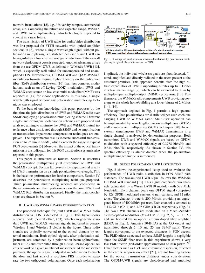
The proposed technique for joint UWB and WiMAX radiodistribution in PON is depicted in Fig. 1. This figure showsa central node (central office, CO), which can generate stan-dard UWB and WiMAX wireless signals, indicated as genericWireless 1 and Wireless 2 blocks in the figure. These radiosignals are typically converted to the optical domain by ex-ternal modulation. Both optical signals, after polarization ad-justment, are combined by a polarization beam splitter/com-biner (PBS) and distributed through a SSMF-based optical ac-cess network to a given number of subscribers. At the subscriberpremises, the optical signal is adjusted in polarization to matchthe slow and fast axis of a reception PBS in order to sepa-rate the two orthogonal polarizations. Once each polarization
Fig. 1. Concept of joint wireless services distribution by polarization multi-plexing in hybrid fiber-radio access on PON.
is splitted, the individual wireless signals are photodetected, fil-tered, amplified and directly radiated to the users present at thecustomer premises. This approach benefits from the high bi-trate capabilities of UWB, supporting bitrates up to 1 Gbit/sat a few meters range [9], which can be extended to 30 m bymultiple-input multiple-output (MIMO) processing [18]. Fur-thermore, the WiMAX radio complements UWB providing cov-erage to the whole home/building at a lower bitrate of 2 Mbit/s[14], [19].
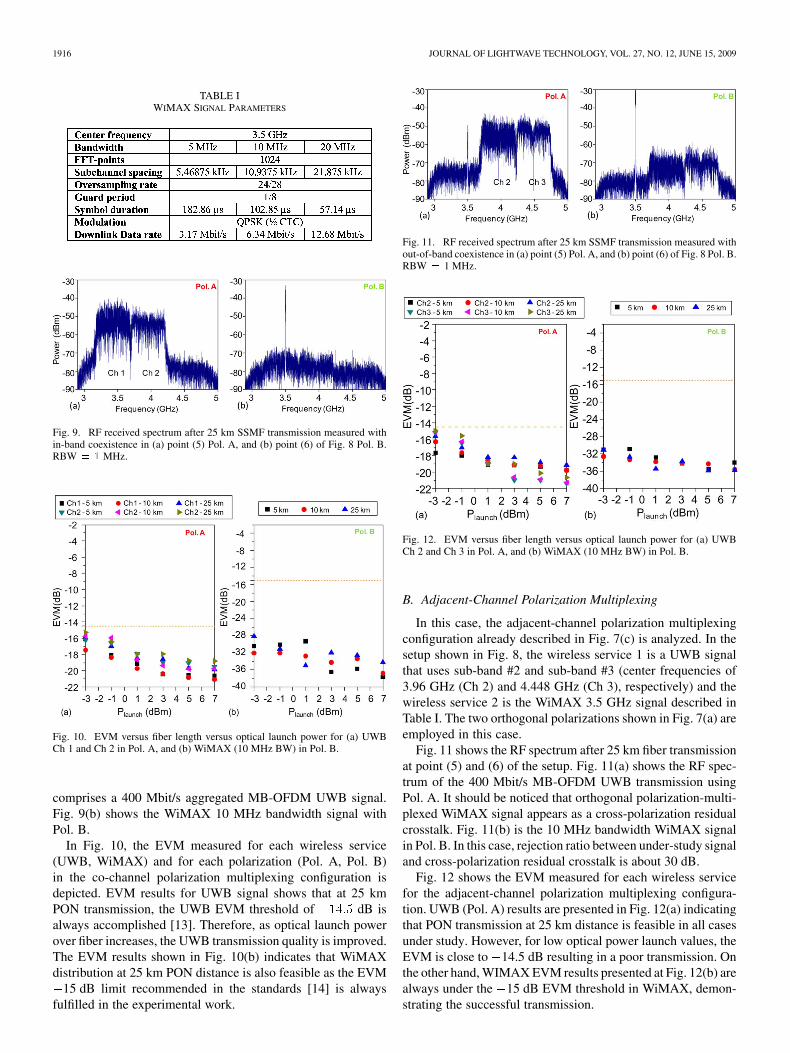
The approach depicted in Fig. 1 permits a high spectralefficiency. Two polarizations are distributed per user, each onecarrying UWB or WiMAX radio. Multi-user operation canbe implemented by wavelength-division multiplexing (WDM)and/or sub-carrier multiplexing (SCM) techniques [20]. In oursystem, simultaneous UWB and WiMAX transmission in asingle channel is analyzed for demonstration purposes. Bothtransmitted UWB and WiMAX signals are based on OFDMmodulation with a spectral efficiency of 0.3788 bit/s/Hz and0.634 bit/s/Hz, respectively. As shown in Section IV, thisspectral efficiency is almost doubled when the polarizationmultiplexing technique is introduced.
III. SINGLE POLARIZATION UWB DISTRIBUTION
Fig. 2 shows the experimental setup used to evaluate theperformance of UWB radio distribution in PON SSMF pathdistances. The transmitted UWB signal follows the WiMediaOFDM-UWB standard [13]. This signal comprises two chan-nels (generated by a Wisair DV9110 module) with 528 MHzbandwidth. Each channel bears one OFDM signal comprisedby 128 QPSK-modulated carriers, 6 null carriers, and 12 pilottones. The channel bitrate is 200 Mbit/s, providing an aggre-gated bitrate of 400 Mbit/s per user. Each channel is centered at3.432 GHz (Ch 1) and 3.96 GHz (Ch 2), respectively (Fig. 3).The two UWB channels are modulated on a Mach–Zehnderelectro-optical modulator (MZ-EOM in Fig. 2, )and are boosted by an optical erbium doped fiber amplifier(EDFA in Fig. 2, Amonics 30-B-FA) at the CO output andtransmitted through 5, 10 and 25 km SSMF paths. Theselengths correspond to the expected distances in PON access.The PMD effect associated to these SSMF lengths is negligiblesince the SSMF fiber used in this experiment shows a verylow PMD factor (first-order approximation) of 0.08 ps/km .Other factors such as GVD and chromatic dispersion, reflectedin the carrier suppression effect [21], are not limiting factorsfor the optical transmission distances under consideration.The OFDM-UWB signals are photodetected and amplified
1914 JOURNAL OF LIGHTWAVE TECHNOLOGY, VOL. 27, NO. 12, JUNE 15, 2009
Fig. 2. Experimental setup for the performance analysis of UWB radio distri-bution on a single wavelength on SSMF at PON distances.
Fig. 3. PSD of the UWB spectrum distributed in single polarization,RBW = 1 MHz. (a) Before optical modulation. (b) After 25 km SSMF trans-mission, photodetection and amplification. The spectral UWB transmissionPSD mask in current regulation [13] is depicted as a dashed line.
adjusting the EIRP to the 41.3 dBm/MHz level allowed inUWB regulation [12].
The error vector magnitude (EVM) is a figure of merit forassessing the quality of digitally modulated communicationsignals. EVM measurements have been performed on a digitalsignal analyzer (Agilent DSA 80000B) to evaluate the linkdegradation experienced by wireless services, in this caseUWB, distribution over the system.
Fig. 3(b) shows the power spectrum density (PSD) of the twoUWB channels where the degradation introduced by 25 km ofoptical transmission SSMF can be observed. It is important topoint out that the received power meets in all the cases the PSDlimit of 41.3 dBm/MHz, and the spectral mask in FCC regu-lation [12]. This guarantees that the received signal at costumerpremises could be radiated just photodetecting, filtering and am-plifying. The increase in the optical power at fiber distributioncan be regulated using a variable attenuator, as shown in Fig. 2.
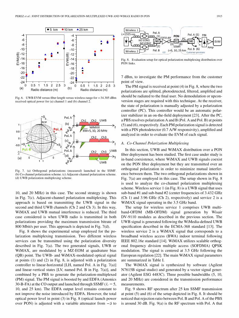
Fig. 4 shows the measured EVM for UWB Ch 1 and Ch 2channels at different optical power levels measured at the PINphotodetector shown in Fig. 2. The EVM results shown in Fig. 4indicate a soft EVM variation when the received optical powervaries in the range under consideration. This UWB EVM vari-ation ranges from 20.75 to 22 dB EVM for Ch 1, and from
21 to 23 dB EVM for Ch 2. The EVM results indicate thesuccessful UWB transmission in the SSMF paths from 5 to25 km, as EVM values are clearly below the 14.5 dB EVMUWB threshold defined in [13].
A. Radio Transmission Penalty
The impact of UWB distribution in SSMF on the radio pathis evaluated in this section. This study aims to ensure that thefiber transmission at PON distances does not strongly affect theradio transmission. In this way, the received UWB signal could
Fig. 4. UWB EVM versus fiber length transmission versus optical power be-fore photodetection for (a) channel 1 and (b) channel 2.
Fig. 5. Experimental setup for the analysis of UWB radio penalty introducedafter 5 to 25 km SSMF optical transmission.
be radiated without special transmission impairments compen-sation algorithms in the OFDM modulation. The performanceis studied measuring the UWB EVM at radio distances from0 to 3 meters after optical transmission through SSMF spans of5, 10, and 25 km.
Fig. 5 shows the experimental setup employed in this case in-cluding the radio transmission path previously discussed. AfterSSMF transmission, the level of OFDM-UWB signals is ad-justed to the PSD regulated level of 41.3 dBm/MHz. Then,the UWB signal is photodetected, filtered, amplified and radi-ated by a 0 dBi gain omnidirectional antenna. This signal is de-tected with a 0 dBi antenna from the same model/manufacturerand its EVM is measured.
The EVM results are shown in Fig. 6. The EVM thresholdlimits the radio distance range after SSMF transmission to 1.5 mfor Ch 1, after up to 10 km SSMF fiber propagation, or to 1 m forall fiber lengths. For Ch 2, the EVM threshold limits radio dis-tance to 1 m in all SSMF paths. These distances are in line withthe UWB performance, and hence, SSMF transmission does notstrongly affect the radio range.
IV. POLARIZATION MULTIPLEXING JOINT DISTRIBUTION
Three different polarization strategies are analyzed for thejoint distribution of UWB and WiMAX radio in this section.These strategies are depicted in Fig. 7(b)–(d). Fig. 7(b) showsthe co-channel polarization multiplexing strategy where theUWB signal is allocated in the first and second UWB channels[13], marked as Ch 1 and Ch 2, and the WiMAX signal isdistributed in the Pol. B shown in Fig. 7(a) at the center fre-quency of 3.5 GHz [22]. This is the most restrictive situationfrom the optical transmission point of view since UWB andWiMAX overlap in frequency but are transmitted in differentpolarizations. Three WiMAX bandwidths are considered (5,
PEREZ et al.: JOINT DISTRIBUTION OF POLARIZATION-MULTIPLEXED UWB AND WIMAX RADIO IN PON 1915
Fig. 6. UWB EVM versus fiber length versus wireless range for�34.305 dBmreceived optical power for (a) channel 1 and (b) channel 2.
Fig. 7. (a) Orthogonal polarizations (measured) launched in the SSMF.(b) Co-channel polarization scheme. (c) Adjacent-channel polarization scheme.(d) UWB polarization multiplexing scheme.
10, and 20 MHz) in this case. The second strategy is shownin Fig. 7(c). Adjacent-channel polarization multiplexing. Thisapproach is based on transmitting the UWB signal in thesecond and third UWB channels (Ch 2 and Ch 3). In this way,WiMAX and UWB mutual interference is reduced. The thirdcase considered is when UWB radio is transmitted in bothpolarizations providing the maximum transmission bitrate of800 Mbit/s per user. This approach is depicted in Fig. 7(d).
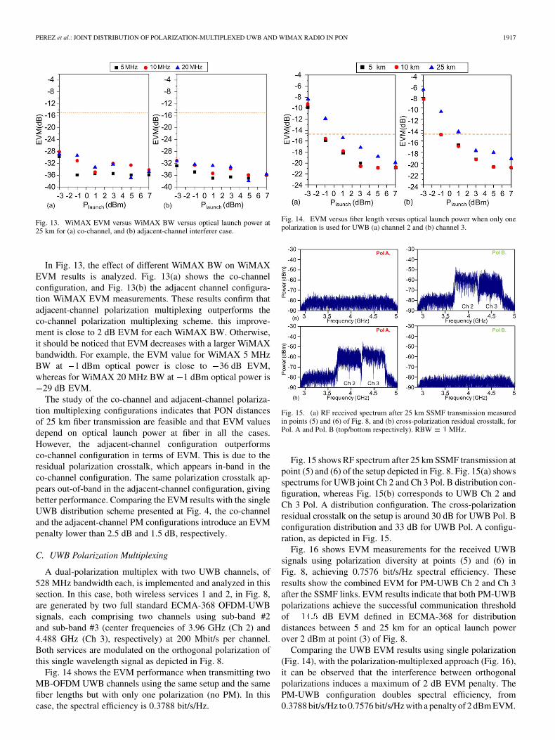
Fig. 8 shows the experimental setup employed for the po-larization multiplexing transmission. Two different wirelessservices can be transmitted using the polarization diversitydescribed in Fig. 7(a). The two generated signals, UWB orWiMAX, are modulated by a MZ-EOM at quadrature bias(QB) point. The UWB- and WiMAX-modulated optical signalat points (1) and (2) in Fig. 8, is adjusted with a polarizationcontroller to linear-horizontal [LH, named Pol. A in Fig. 7(a)]and linear-vertical states [LV, named Pol. B in Fig. 7(a)], andcombined by a PBS to generate the polarization-multiplexed(PM) signal. The PM signal is boosted by and EDFA (Amonics30-B-FA) at the CO output and launched through SSMF ( 5,10, and 25 km). The EDFA output level remains constant tonot improve the noise introduced by EDFA. However, the totaloptical power level in point (3) in Fig. 8 (optical launch powerover PON) is adjusted with a variable attenuator from to
Fig. 8. Evaluation setup for optical polarization multiplexing distribution overPON links.
7 dBm, to investigate the PM performance from the customerpoint of view.
The PM signal is received at point (4) in Fig. 8, where the twopolarizations are splitted, photodetected, filtered, amplified andshould be radiated to the final user. No demodulation or upcon-version stages are required with this technique. At the receiver,the state of polarization is manually adjusted by a polarizationcontroller (PC). This controller would be an automatic polar-izer stabilizer in an on-the-field deployment [23]. After the PC,a PBS resolves polarization A and B (Pol. A and Pol. B) at points(5) and (6), respectively. Each PM polarization signal is detectedwith a PIN photodetector (0.7 A/W responsivity), amplified andanalyzed in order to evaluate the EVM of each signal.
A. Co-Channel Polarization Multiplexing
In this section, UWB and WiMAX distribution over a PONfiber deployment has been studied. The first case under study isin-band coexistence, where WiMAX and UWB signals coexiston the PON fiber deployment but they are transmitted over anorthogonal polarization in order to minimize mutual interfer-ence between them. The two orthogonal polarizations shown inFig. 7(a) are employed in this case. The setup shown in Fig. 8is used to analyze the co-channel polarization multiplexingscheme. Wireless service 1 (in Fig. 8) is a UWB signal that usessub-band #1 and sub-band #2 (center frequencies of 3.432 GHz(Ch 1) and 3.96 GHz (Ch 2), respectively) and service 2 is aWiMAX signal operating in the 3.5 GHz band.
The setup for wireless service 1 comprises UWB multi-band-OFDM (MB-OFDM) signal generation by WisairDV-9110 modules as described in the previous section. TheUWB signal is generated following the WiMedia-defined UWBspecification described in the ECMA-368 standard [13]. Thewireless service 2 is a WiMAX signal that corresponds to abroadband wireless access (BWA) indoor terminal followingIEEE 802.16e standard [14]. WiMAX utilizes scalable orthog-onal frequency division multiple access (SOFDMA) QPSKmodulation. The signal is centered at 3.5 GHz following theEuropean regulation [22]. The main WiMAX signal parametersare summarized in Table I.
The WiMAX signal is synthesized by software (AgilentN7615B signal studio) and generated by a vector signal gener-ator (Agilent ESG 4483C). Three possible bandwidths (5, 10,and 20 MHz) are considered in the transmission performancemeasurements.
Fig. 9 shows RF spectrum after 25 km SSMF transmissionat point (5) and (6) of the setup depicted in Fig. 8. It should benoticed that rejection ratio between Pol. B and Pol. A of the PBSis around 30 dB. Fig. 9(a) is the RF spectrum with Pol. A that
1916 JOURNAL OF LIGHTWAVE TECHNOLOGY, VOL. 27, NO. 12, JUNE 15, 2009
TABLE IWIMAX SIGNAL PARAMETERS
Fig. 9. RF received spectrum after 25 km SSMF transmission measured within-band coexistence in (a) point (5) Pol. A, and (b) point (6) of Fig. 8 Pol. B.RBW � � MHz.
Fig. 10. EVM versus fiber length versus optical launch power for (a) UWBCh 1 and Ch 2 in Pol. A, and (b) WiMAX (10 MHz BW) in Pol. B.
comprises a 400 Mbit/s aggregated MB-OFDM UWB signal.Fig. 9(b) shows the WiMAX 10 MHz bandwidth signal withPol. B.
In Fig. 10, the EVM measured for each wireless service(UWB, WiMAX) and for each polarization (Pol. A, Pol. B)in the co-channel polarization multiplexing configuration isdepicted. EVM results for UWB signal shows that at 25 kmPON transmission, the UWB EVM threshold of dB isalways accomplished [13]. Therefore, as optical launch powerover fiber increases, the UWB transmission quality is improved.The EVM results shown in Fig. 10(b) indicates that WiMAXdistribution at 25 km PON distance is also feasible as the EVM
15 dB limit recommended in the standards [14] is alwaysfulfilled in the experimental work.
Fig. 11. RF received spectrum after 25 km SSMF transmission measured without-of-band coexistence in (a) point (5) Pol. A, and (b) point (6) of Fig. 8 Pol. B.RBW � 1 MHz.
Fig. 12. EVM versus fiber length versus optical launch power for (a) UWBCh 2 and Ch 3 in Pol. A, and (b) WiMAX (10 MHz BW) in Pol. B.
B. Adjacent-Channel Polarization Multiplexing
In this case, the adjacent-channel polarization multiplexingconfiguration already described in Fig. 7(c) is analyzed. In thesetup shown in Fig. 8, the wireless service 1 is a UWB signalthat uses sub-band #2 and sub-band #3 (center frequencies of3.96 GHz (Ch 2) and 4.448 GHz (Ch 3), respectively) and thewireless service 2 is the WiMAX 3.5 GHz signal described inTable I. The two orthogonal polarizations shown in Fig. 7(a) areemployed in this case.
Fig. 11 shows the RF spectrum after 25 km fiber transmissionat point (5) and (6) of the setup. Fig. 11(a) shows the RF spec-trum of the 400 Mbit/s MB-OFDM UWB transmission usingPol. A. It should be noticed that orthogonal polarization-multi-plexed WiMAX signal appears as a cross-polarization residualcrosstalk. Fig. 11(b) is the 10 MHz bandwidth WiMAX signalin Pol. B. In this case, rejection ratio between under-study signaland cross-polarization residual crosstalk is about 30 dB.
Fig. 12 shows the EVM measured for each wireless servicefor the adjacent-channel polarization multiplexing configura-tion. UWB (Pol. A) results are presented in Fig. 12(a) indicatingthat PON transmission at 25 km distance is feasible in all casesunder study. However, for low optical power launch values, theEVM is close to 14.5 dB resulting in a poor transmission. Onthe other hand, WIMAX EVM results presented at Fig. 12(b) arealways under the 15 dB EVM threshold in WiMAX, demon-strating the successful transmission.
PEREZ et al.: JOINT DISTRIBUTION OF POLARIZATION-MULTIPLEXED UWB AND WIMAX RADIO IN PON 1917
Fig. 13. WiMAX EVM versus WiMAX BW versus optical launch power at25 km for (a) co-channel, and (b) adjacent-channel interferer case.
In Fig. 13, the effect of different WiMAX BW on WiMAXEVM results is analyzed. Fig. 13(a) shows the co-channelconfiguration, and Fig. 13(b) the adjacent channel configura-tion WiMAX EVM measurements. These results confirm thatadjacent-channel polarization multiplexing outperforms theco-channel polarization multiplexing scheme. this improve-ment is close to 2 dB EVM for each WiMAX BW. Otherwise,it should be noticed that EVM decreases with a larger WiMAXbandwidth. For example, the EVM value for WiMAX 5 MHzBW at 1 dBm optical power is close to 36 dB EVM,whereas for WiMAX 20 MHz BW at 1 dBm optical power is
29 dB EVM.The study of the co-channel and adjacent-channel polariza-
tion multiplexing configurations indicates that PON distancesof 25 km fiber transmission are feasible and that EVM valuesdepend on optical launch power at fiber in all the cases.However, the adjacent-channel configuration outperformsco-channel configuration in terms of EVM. This is due to theresidual polarization crosstalk, which appears in-band in theco-channel configuration. The same polarization crosstalk ap-pears out-of-band in the adjacent-channel configuration, givingbetter performance. Comparing the EVM results with the singleUWB distribution scheme presented at Fig. 4, the co-channeland the adjacent-channel PM configurations introduce an EVMpenalty lower than 2.5 dB and 1.5 dB, respectively.
C. UWB Polarization Multiplexing
A dual-polarization multiplex with two UWB channels, of528 MHz bandwidth each, is implemented and analyzed in thissection. In this case, both wireless services 1 and 2, in Fig. 8,are generated by two full standard ECMA-368 OFDM-UWBsignals, each comprising two channels using sub-band #2and sub-band #3 (center frequencies of 3.96 GHz (Ch 2) and4.488 GHz (Ch 3), respectively) at 200 Mbit/s per channel.Both services are modulated on the orthogonal polarization ofthis single wavelength signal as depicted in Fig. 8.
Fig. 14 shows the EVM performance when transmitting twoMB-OFDM UWB channels using the same setup and the samefiber lengths but with only one polarization (no PM). In thiscase, the spectral efficiency is 0.3788 bit/s/Hz.
Fig. 14. EVM versus fiber length versus optical launch power when only onepolarization is used for UWB (a) channel 2 and (b) channel 3.
Fig. 15. (a) RF received spectrum after 25 km SSMF transmission measuredin points (5) and (6) of Fig. 8, and (b) cross-polarization residual crosstalk, forPol. A and Pol. B (top/bottom respectively). RBW � � MHz.
Fig. 15 shows RF spectrum after 25 km SSMF transmission atpoint (5) and (6) of the setup depicted in Fig. 8. Fig. 15(a) showsspectrums for UWB joint Ch 2 and Ch 3 Pol. B distribution con-figuration, whereas Fig. 15(b) corresponds to UWB Ch 2 andCh 3 Pol. A distribution configuration. The cross-polarizationresidual crosstalk on the setup is around 30 dB for UWB Pol. Bconfiguration distribution and 33 dB for UWB Pol. A configu-ration, as depicted in Fig. 15.
Fig. 16 shows EVM measurements for the received UWBsignals using polarization diversity at points (5) and (6) inFig. 8, achieving 0.7576 bit/s/Hz spectral efficiency. Theseresults show the combined EVM for PM-UWB Ch 2 and Ch 3after the SSMF links. EVM results indicate that both PM-UWBpolarizations achieve the successful communication thresholdof dB EVM defined in ECMA-368 for distributiondistances between 5 and 25 km for an optical launch powerover 2 dBm at point (3) of Fig. 8.
Comparing the UWB EVM results using single polarization(Fig. 14), with the polarization-multiplexed approach (Fig. 16),it can be observed that the interference between orthogonalpolarizations induces a maximum of 2 dB EVM penalty. ThePM-UWB configuration doubles spectral efficiency, from0.3788 bit/s/Hz to 0.7576 bit/s/Hz with a penalty of 2 dBm EVM.
1918 JOURNAL OF LIGHTWAVE TECHNOLOGY, VOL. 27, NO. 12, JUNE 15, 2009
Fig. 16. EVM versus fiber length launch power versus optical launch powerfor joint PM-UWB Ch 2 and Ch 3 transmission for (a) Pol. A and (b) Pol. B.
V. CONCLUSION
In this paper, the feasibility of polarization-division schemesfor the joint distribution of UWB and WiMAX radio has beenevaluated considering four single- and orthogonal-polarizationdifferent schemes for the optical transmission co-existence.
First, a single-polarization UWB transmission with 0.3788bit/s/Hz spectral efficiency is reported achieving 25 kmreach with 21.5 dB EVM, which indicates the baselineperformance. Second, the proposed co-channel polarizationmultiplexing scheme for UWB and WiMAX is measured.This scheme achieves 25 km reach with 17.5 dB EVM forUWB signal and 31 dB EVM for WiMAX signal. The UWBspectral efficiency obtained is 0.3788 bit/s/MHz. Third, theadjacent-channel UWB and WiMAX polarization multiplexingproposed scheme is demonstrated with 0.3788 bit/s/Hz spectralefficiency for UWB signal transmission. Adjacent-channelpolarization multiplexing scheme achieves 25 km reach with
18 dB EVM for UWB signal and 32.5 dB EVM for WiMAXsignal. Finally, the UWB orthogonal polarization multiplexingscheme is reported with 0.7576 bit/s/Hz spectral efficiency.This scheme achieves 25 km reach with 2 dB EVM penaltycompared with UWB single-polarization distribution scheme.
The experimental results demonstrate the feasibility of thepolarization-division technique proposed for typical PON dis-tances. This technique enables the joint distribution of UWBand WiMAX. Adequate polarization tracking, photodection, fil-tering and amplification stages at the customer premises are re-quired for on-the-field deployment.
ACKNOWLEDGMENT
The authors would like to acknowledge the kind support ofthe Radio Access and Spectrum (RAS) Cluster Organised byUnit D1 of the DG INFOSYS and MEDIA of the Commissionof the European Communities (http://www.newcom-project.eu:8080/Plone/ras), and the support of the BONE (“Buildingthe Future Optical Network in Europe”) Network of Excel-lence (http://www.ict-bone.eu), both funded by the EuropeanCommission.
REFERENCES
[1] J. O. Farmer and K. Bourg, “Practical deployment of passive opticalnetworks,” IEEE Commun. Mag., vol. 46, no. 7, pp. 136–145, Jun.2008.
[2] T. Koonen, M. G. Larrodé, P. Urban, H. Waardt, C. Tsekrekos, J. Yang,H. Yang, and H. Boom, “Fiber-based versatile broadband access andin-building networks,” in IET Workshop From Access to Metro, BB Eu-rope, Belgium, Dec. 2007.
[3] P. W. Shumate, “Fiber-to-the-Home: 1977–2007,” IEEE J. Lightw.Technol., vol. 26, no. 9, pp. 1093–1103, May 2008.
[4] N. Genay, P. Chanclou, F. Saliou, Q. Liu, T. Soret, and L. Guillo, “So-lutions for budget increase for the next generation optical access net-worke,” in Proc. ICTON ’07, Jul. 2007, vol. 1, pp. 317–320.
[5] L. Rerko, “Triple-play service deployment: a comprehensive guide totest,measurement, and service assurance,” JDS Uniphase Corp., Mil-pitas, CA, 2007.
[6] H. Pfrommer, M. A. Piqueras, V. Polo, and J. Marti, “Full-duplexdocsis/wirelessDOCSIS small-scale field trial employing hybrid fiberradio systems,” in Proc. IEEE MTT-S Int. Microwave Symp. Dig., Jun.2006, pp. 26–29.
[7] A. Kim, Y. H. Joo, and Y. Kim, “60 GHz wireless communicationsystems with radio-over-fiber links for indoor wireless LANs,” IEEETrans. Consum. Electron., vol. 50, no. 2, pp. 517–520, May 2004.
[8] R. Llorente, T. Alves, M. Morant, M. Beltran, J. Perez, A. Cartaxo,and J. Marti, “Ultra-wideband radio signals distribution in FTTH net-works,” IEEE Photon. Technol. Lett., vol. 20, no. 11, pp. 945–947, Jun.1, 2008.
[9] T. Lunttila, S. Iraji, and H. Berg, “Advanced coding schemes for amultiband OFDM ultrawideband system towards 1 Gbps,” in Proc.IEEE 3rd Consumer Communications and Networking Conf., Jan.2006, vol. 1, pp. 553–557.
[10] R. Kohno, “State of arts in ultra wideband (UWB) wireless technologyand global harmonization,” in Proc. 34th European Microwave Conf.,Oct. 2004, vol. 2, pp. 1093–1099.
[11] WHDI Special Interest Group. [Online]. Available: http://www.whdi.org/
[12] Revision of Part 15 of the Commission’s Rules Regarding Ultra-Wide-band Transmission Systems. FCC 02-48, 2002.
[13] High Rate Ultra Wideband PHY and MAC Standard. ECMA 368 In-ternational Standard, 2005.
[14] IEEE Standard for Local and Metropolitan Area Networks; Part 16: AirInterface for Fixed Broadband Wireless Access Systems, Amendment 2:Physical and Medium Access Control Layers for Combined Fixed andMobile Operation in Licensed Bands and Corrigendum 1, IEEE Std802.16e-2005, 2006.
[15] “Can WiMAX Address Your Applications?” Westech CommunicationsInc., Hayward, CA, WiMax Forum Whitepaper, 2005.
[16] T. Alves and A. Cartaxo, “Performance degradation due toOFDM-UWB radio signal transmission along dispersive single-modefiber,” IEEE Photon. Technol. Lett., vol. 21, no. 3, pp. 158–160, Feb.1, 2009.
[17] R. Alemany, J. Perez, R. Llorente, V. Polo, and J. Marti, “Coexistenceof WiMAX 802.16d and MB-OFDM UWB in radio over multi-modefiber indoor systems,” in Proc. Int. Topics Meeting on Microwave Pho-tonics (MWP’08), Oct. 2008, pp. 74–77.
[18] Q. Zou, A. Tarighat, and A. H. Sayed, “Performance analysis of multi-band OFDM UWB communications with application to range improve-ment,” IEEE Trans. Veh. Technol., vol. 56, pt. 2, pp. 3864–3878, Nov.2007.
[19] IEEE Standard for Local and Metropolitan Area Networks; Part 16: AirInterface for Fixed Broadband Wireless Access, IEEE Std 802.16-2004,2004.
[20] Q. Chang, J. Gao, Q. Li, and Y. Su, “Simultaneous transmissionof point-to-point data and selective delivery of video services in aWDM-PON using ASK/SCM modulation format,” in Proc. OpticalFiber Commun. Conf. Expo. (OFC), Feb. 2008, paper OWH2, pp. 1–3.
[21] H. Schmuck, “Comparison of optically millimeter-wave system con-cepts with regard to chromatic dispersion,” Electron. Lett., vol. 31, no.21, pp. 1848–1849, Oct. 1995.
[22] ECC Decision of 30 March 2007 on Availability of Frequency BandsBetween 3400–3800 MHz for the Harmonized Implementation ofBroadband Wireless Access systems (BWA). Electronic Communica-tions Committee (ECC), ECC/DEC/(07)02.
[23] “Reset-Free Polarization Stabilizer—PolaStay™,” General Pho-tonics [Online]. Available: http://www.generalphotonics.com/pdf/PolaStay.pdf

PEREZ et al.: JOINT DISTRIBUTION OF POLARIZATION-MULTIPLEXED UWB AND WIMAX RADIO IN PON 1919
Joaquin Perez received the Ingeniero de Telecomu-nicación degree from the Universidad Politécnica deValencia, Spain, in 2004, and the M.Sc. degree fromthe same university in 2007.
Since 2004, he has been collaborating with theValencia Nanophotonics Technology Center (NTC)of the Universidad Politécnica de Valencia, Spain,in wireless photonic integration communicationsystems and ultra-wideband radio over fiber systems.He is involved in several national and Europeanprojects including FP7-ICT-UCELLS. He is cur-
rently working toward the Ph.D. degree at NTC on wireless transmissionsintegration and coexistence in optical transmission systems. His researchinterests include optical access networks, emerging radio technologies, opticalprocessing, and microwave photonics.
Maria Morant received the M.Sc. degree intelecommunication engineering from the Univer-sidad Politécnica de Valencia, Spain, in 2008. Sheis currently working towards the Ph.D. degree intelecommunications and wireless photonics integra-tion at Valencia Nanophotonics Technology Center(NTC). Since 2006, she has been collaboratingwith the NTC in ultra-wideband radio signalspropagation over optical fiber and is working onEuropean projects including FP6-IST-UROOF andFP7-ICT-UCELLS. Her current research areas of
interest include ultra-wideband communications on fiber-optic networks.
Roberto Llorente received the M.Sc. degree intelecommunication engineering and the Ph.D. de-gree from the Universidad Politécnica de Valencia,Valencia, Spain, in 1998 and 2006, respectively.
Since then, he has been in research positions withinthe Fiber-Radio Systems Group of the same univer-sity. In 2002, he joined the Valencia NanophotonicsTechnology Center (NTC), where he has participatedin several national and European research projectson areas such as bio-photonics, optical signal pro-cessing, and OTDM/DWDM transmission systems.
Currently, he is an Associate Professor of the Universidad Politécnica de Va-lencia in the Communications Department, teaching radio-communications-re-lated subjects. He has been the Technical Responsible of the European projectFP6-IST-UROOF in the NTC, and, from January 2008, Coordinator of the Eu-ropean project FP7-ICT-UCELLS. His research interest includes optical andelectro-optical processing techniques in the areas of transmission systems andhybrid wireless-optical access networks. He has authored or coauthored morethan 40 papers in leading international journals and conferences and has au-thored three patents.
Javier Martí received the Ingeniero de Telecomu-nicación degree from the Universidad Politécnicade Catalunya, Spain, in 1991, and the Ph.D. degreefrom the Universidad Politécnica de Valencia, Spain,in 1994.
During 1989 and 1990, he was an Assistant Lec-turer at the Universidad Politécnica de Catalunya.During 1991–2000, he obtained the positions ofLecturer and Associate Professor at the Telecommu-nication Engineering Faculty, where he is currently aFull Professor and leads the Fibre-Radio Group. He
is the Director of the Valencia Nanophotonics Technology Center (NTC), a na-tional research center for photonic technologies in Spain. He has authored sevenpatents and over 185 papers in refereed international technical journals in thefields of fiber-radio systems, technologies and access networks. He has led manynational and international research projects including FP5-IST-TOPRATE andhas been the coordinator of the FP5-IST-OBANET and FP6-IST-GANDALFprojects. He is currently participating in IST-LASAGNE and coordinatingFP6-IST&NMP-PHOLOGIC.
Prof. Martí is or has been a member of the Technical Program Committee ofseveral conferences including ECOC, LEOS, Microwave Photonics, and sev-eral other international workshops. He is currently involved in launching NTCspin-off companies addressing photonic wireless technologies. He is the recip-ient of several academic and industrial awards in Spain.