
OUTSIDE TMP 32
The One of a Kind UT3000 Zone Control System provides intelligent
control of a communicating HVAC system or 24volt legacy HVAC
system at a maximum of three zones using 24volt motorized dampers
and any off-the-shelf 24volt thermostat or compatible
communicating thermostat. The UT3000 is 100% plug and play when
connected to a communicating HVAC system and network
thermostats. The UT3000 includes features such as Proportional
Operation, Automatic Equipment Recognition, Dual Fuel Functions
and Precise Control of Supply Air Target & Limit set-points.
EWC® Controls raises the bar again and sets another new standard
for Residential and Light Commercial HVAC Air Zoning.
Control Any Communicating HVAC
system based on the ClimateTalk™ Open
Protocol. Or any 24volt 2 Heat / 1 Cool
Gas/Electric system or 2 Heat / 1 Cool
Conventional or Dual Fuel Heat Pump.
The UT3000 panel features automatic
changeover from any thermostat allowing
for individual zone comfort from the
zoned HVAC system.
The Liquid Crystal Display scrolls to
show current zone thermostat demand
input and HVAC system demand output.
In addition, all programming is performed
at the LCD.
In addition to the LCD, a total of 5 colored
LED’s provide indication of the HVAC
system status and mode of operation.
A total of 3 green LED’s labeled Zone 1
thru Zone 3, are also provided to indicate
which dampers are energized to Open.
A total of 4 green Pulsing LED’s are provided to
indicate a Comm Link has been established with each
Communicating T-stat and/or the Communicating
HVAC system. A series of Rapid & Random Pulses
indicate a successful link and data transmission.
Otherwise, the Comm LED’s will blink On & Off
very slowly for non-communicating devices.
The UT3000 includes a SPDT Dry Relay with an
Input Trigger that can be used to Connect, Interlock
and Control Ancillary IAQ devices:
Fresh Air Damper * Whole House Humidifiers
Heat Recovery Ventilator * Energy Recovery Ventilator
Whole House De-humidifiers * Combustion Air Damper
The UT3000 will start the Indoor Fan when the Dry
Relay Input is Energized. Connected Zone Dampers
operate normally and are not affected by the relay’s
function.
Four buttons are provided just below the
LCD screen. The buttons are used to scroll
thru the Menu on the LCD and make your
selections. Program the UT3000 and
select the features you like. Non-volatile
memory maintains your settings even
after a long power failure.
Figure 1. UT3000 panel
EWC Controls Inc. 385 Highway 33 Englishtown, NJ 07726 800-446-3110 FAX 732-446-5362 E-Mail- [email protected]
TB-241P/N 090375A0241 REV. F Copyright © January 2011 EWC Controls Inc. ALL Rights Reserved
LEAVE THIS BULLETIN ON THE JOB SITE FOR FUTURE REFERENCE
The UT3000 is compatible with any
Communicating Thermostat that operates
on the ClimateTalk™ Open Protocol. Also
compatible with any off-the shelf single
stage 24volt Heat/Cool Thermostat or
2 Heat/1Cool Heat Pump Thermostat.
Controls two or three air zones with 24vac
Power Open/Close or Spring Assisted
motorized dampers.
CompatibleHVAC Systems
ZoneCapacity
CompatibleThermostats
AutomaticHeat / CoolChangeover
Status LCD
Forward
Back
Select Up
Select Down
4 Button LCDProgramming
System LED’s
Damper LED’s
Communicating
LED’s
Fault FreeProgramming & Intuitive Temperature Control
Ancillary IAQ Dry Relay Provided
C
EWC
SYSTEMCONTROL
PC
PO
C
2
1
R
C
PC
PO
C
2
1
R
C
W/E
O/B
Y
R
G
R
C
W2/E
W1/B
O
Y
G
RH
RC
C
C
2
1
R
C
W/E
O/B
Y
R
G
ZONEZONE
DRY RELAY
SYSTEM
ZONE 3 OPEN
ZONE 2 OPEN
ZONE 1 OPEN
DRY RELAY
W2 / EMERGENCY
HEAT / B
COMPRESSOR
FAN
C
2
1
LED16
LED17
LED15
LED14
LED13
LED12
LED11
LED10
SWT1
SWT2
SWT3
SWT4
ClimateTalkTM
CONTRAST
LED19
LED22
RC/RHLINK
JMP1
LED20
BIASINGTERMINATION
SYSTEM CLIMATE TALK
RECEIVE DATA
DAMPER
DAMPER
DAMPER
C
PC
PO
SYSTEM
F8 D20 C42 L2
+C9+
D28
FB2
C8+ U17
D19
R38D18R37D17
R41
R40
R79
F7
F6
C32U12
C16
R13
K9
D16
D15
C15
D14
D13
R25
R26
C31
C29
C28
C26
R71
R75
R77
R84
R83
R76
R74
R70
R69
R68
C30
R46
U16
R116R111
U15
R114
R110
U14
R115
R113
R112
R43
R118
C41
R45
R119
C43
R109
R39
D12
K8
R12
D11
K7
R11
D10
R10K6
D9
R9
D8 C21
Y1
C14
U3 U4
C22
R117
J1
R27
C13
R28
U7
U6
C19
U18
R8 R7 R6
C12
R67
C25
R66
R64
R63
R62
R65
R73
C24
C27
R72R58
D25F17
F5
R57
C23
U11
R60
R80
R61
R91
R88
R94
R93
R92
R96
R97
R95
C33
C34
R86
R85
R87C35
C36R98
F16
F21
D24F15
R53R56
R81R55
K3 F4F14D23
R52R54C20U10
D27F1
D1 D2FB1
C2 C1 C3
+ + +
U19
C10
R101C37 R90
R103
R102
R104
R107
R105
R106
R108
C38
C39
R89
R100
R99C40
D21
F11
C18R47 R49
F13
F22
F3
D22
F12K2
R48
D5
R51
R82
R50
U9
K5
23
C4 C5+
+
L1
D3U2
R22
R35
R36
R33
R34
SAS
C
W/E
O/B
Y
R
G
Dry RONEZONE
ZONE
R
R23
R24
F19
F20
D26
F18
1
OAS
Z1RXD
Z2RXDZ3RXD
LED21
UT3000
NC
NO
C
The UT3000 comes pre-loaded with Default
Operating Parameters for Zoned HVAC Systems. The
Default Program Settings free the Technician from
Programming but also allows Fine Tuning of the
System to Optimize Performance and Personal
Preference. The UT3000 operates in Proportional
Mode at all times. Multi-Stage and Modulating
Equipment will be operated in a manner that
Minimizes Blower Speed, Maximizes Temperature
Control and Improves System Efficiency.
®
®
Forced Air Zone Controls
W
Y
G
R
Communicating Zone Control System
TM
3000
1
2
3
ON

Forward
Back
INSTALLATION INSTRUCTIONS
UT3000 Version 1.06 SPECIFICATIONS:
NUMBER OF ZONES: 2 or 3 Zones, Non-Expandable
COMPATIBLE EQUIPMENT: Climate Talk™ based Communicating HVAC systems - Up to 4 Stages Heating and 2 Stages CoolingGas/Electric/Hydro – Up to 2 Stages Heating and 1Stage CoolingHeat Pump Conventional or Dual Fuel – Up to 2 Stages Heating and 1 Stage Cooling
COMPATIBLE THERMOSTATS: Climate Talk™ based Communicating HVAC ThermostatAny single stage Heat/Cool ThermostatAny 2 Stage Heat, 1 Stage cool Heat Pump Thermostat
COMPATIBLE DAMPERS: EWC® Ultra-Zone® Models URD, ND, RSD and SID, Or Any Competitor’s 24vac 3 Wire or 2 Wire damperMAX. DAMPERS PER ZONE:Up to 18 ND, URD, or SID Dampers Per Zone @ 26mA per damper. Total 54Only 1 Spring Type Damper Per Zone @ 400mA per damper. Total 3
OVER-CURRENT PROTECTION: 2.5Amp main circuit board protection500mA on each Damper Motor Terminal Block
140mA on each Communicating Thermostat and HVAC System Terminal Block
140mA on each Regular 24v Thermostat Terminal Block
UT3000 MAXIMUM CURRENT DRAW = .5 Amp
POWER REQUIREMENT = 24Vac 40Va 50/60 Hz
AMBIENT OPERATING CONDITIONS:
TEMPERATURE: -4° to 158°F (-20° to 70°C)
HUMIDITY: 0% - 95% Rh Non-Condensing
ANCILLARY IAQ DRY RELAY FUNCTIONS:Operate a Humidifier or De-HumidifierControl a Fresh Air or Combustion Air DamperOperate & Interlock an ERV or HRV
ACCESSORIES: Model SAS – Supply Air Sensor (Included)Model OAS – Outdoor Air Sensor (Optional/Recommended)Model CPLS – Coil Protection Lockout Switch (Optional/Recommended)
MOUNT: Choose a suitable location to mount the UT3000 housing. Likely locations are the Return Duct, a Nearby Wall or Convenient Studs where plywood can be installed to support the housing. Avoid mounting the UT3000 on the Supply duct. Do not mount the UT3000 directly to any Air-Handler, Furnace, Hot Water Coil or Evaporator Cabinet to avoid damage to these devices. Follow National and/or Local Mechanical Code.
POWER:EWC always recommends to install a separate transformer to power the UT3000. Follow NEC and/or Local Electrical Code.
WIRE:Connect your thermostats and your dampers. Use the provided knock-outs as the wire entry-way. Strip the jacket back to where the cable enters the housing. That makes for less bulk and allows easy routing of the wires for a clean install.
4 Wire Comm Network:Adhere to the Climate Talk™ Color Code. RED, GREEN, YELLOW, WHITE. Doing so reduces the possibility of mis-wiring between devices on the Network.
PROGRAM:When connected to a Fully Communicating HVAC system, programming is not required. The UT3000 will automatically configure the entire system and start running as soon as thermostat demands are detected. Allow at least 1-2 minutes for all Thermostats and the HVAC system to fully configure on the network. The Default Supply air temperature Targets and off-set Limits will be used. Other unique features can be selected and/or you can adjust the default settings yourself.
When connected to a Conventional 24v HVAC system, you simply scroll thru the LCD menu and select the type of HVAC system you have and the type of thermostats you want to use. The Default Supply air temperature Targets and off-set Limits will be used, or you can adjust your own settings.
FINISH:When the Installation is complete, run the system thru it’s paces and observe the operation of the HVAC system in all possible modes of operation. Check the Zone Dampers and the Bypass Damper for proper operation. Balance the System and make adjustments as necessary. If you need help, call the Technical Support Hotline for assistance 800-446-3110.
2EWC Controls Inc. 385 Highway 33 Englishtown, NJ 07726 800-446-3110 FAX 732-446-5362 E-Mail- [email protected]
FEATURE DEFAULT RANGE TO SELECT
System Type
HP Type
T-Stat Type
Rev Valve
Fan Mode
Heat/Cool
NONDual Fuel
RV ‘O’
Hydro
OAS SP 15°
O.T. Offset 15°
10°U.T. Offset
SAS HP TGT
SAS Gas TGT
SAS Cool TGT
110°
140°
55°
PURGE FAN
SAS RSP DLY
W2 Threshold
60s
85%
25%
Heat Pump or Heat/Cool
Dual Fuel or Non-Dual Fuel
Heat Pump or Heat/Cool
‘O’ Type RV or ‘B’ Type RV
GAS or HYDRO (Electric)
OFF or 7° to 42° F.
5° to 20° F.
5° to 12° F.
90° to 120° F.
120° to 170° F.
45° to 60° F.
10seconds - 180seconds
65% - 99% (Adj. in 5 point increments)
0% - 100% (Adj. in 25 point increments)
Field Supplied * Dedicated * Listed Transformer
24vac 40va Min / 60va Max
To Zone Control Panel
To Protected LineVoltage
R
C
10.00”1.70”
9.875”CONTROLS INC.EW
NOMINAL DIMENSIONS
10” X 10” X 1.75”
CONTROLS INC.
EW
OK
WHITE
YELLOW
GREEN
RED
2
1
C
R
FROMCOMMUNICATINGHVAC SYSTEMorCOMMUNICATINGTHERMOSTAT
Typical Up-flow Installation with DX Cooling
Avoid mounting in these locations
Upon Power Up, Press and Hold the Back & Forward buttons to Load the Factory Default Values, then Release.
Default Loaded
Power Supply
If desired, you can reset the UT3000.
Install a Separate Transformer to Power the UT3000
Stick with the Color Code & Protectthe Wires
Heat/Cool

Fan Mode N/A
If you selected a Heat Pump system in Step 1 and Heat Pump Thermostats in Step 3, then select the type of Reversing Valve Operation.
Select how you want the Indoor Fan to operate during Heating Operations. Select HYDRO if you have an Air-Handler with Hot Water Coil or an Electric Furnace. Select GAS if your system is a Gas/Oil Furnace with A/C. If you selected a Heat Pump system in Step 1, the Fan Mode is set for you, in which case you’ll see Fan Type N/A.
If you are using an Outside Air Sensor to Lock-Out the Heat Pump when the outside temperature drops low enough, choose the Set-Point Temperature.
If the Supply Air Temperature exceeds any Target Set-Point, (Plus or Minus the Off-Set), the resulting value becomes the Temperature Limit. Choose an Off-Set value that will provide a safe operating limit for your HVAC equipment. The UT3000 will cycle the system off for 3 minutes, allowing the discharge air temperature to moderate.
LCD Screen Programming
Select either Heat Pump or regular Heat/Cool system. If you have a Heat Pump and a Gas/Oil Furnace, you should still select Heat Pump.
If you selected a Heat Pump system in Step 1, select whether your Heat Pump has a Furnace back-up system or Electric Heat back-up.You can still operate most any Heat Pump in a restricted mode by using an Outdoor Sensor.
Select the type of 24v (Non-Communicating) Thermostat you want to use. You may have a Communicating thermostat in Zone 1 and Regular 24v thermostats in the other zones. So you must select which type are in the other zones. You cannot mix 24v HP and HC type T-stats. All 24v T-stats must be Wired and/or Programmed for HC or HP Mode of Operation and the correct Reversing Valve Operation. Conflicting Zone Demands due to mis-wiring or incorrect programming will not be honored!
4 Button LCDProgramming
Remember if you are installing a Communicating HVAC system, the programming is done for you. There is no need to perform these Programming steps. You can still program certain detail functions ie. (24v T-stat Type). Select only the functions you want or need. Your program changes take effect in real time and the UT3000 will remember your settings even after a power failure. When the power is restored, the UT3000 will re-configure the network automatically.
Heat Cool System
Heat Pump System
OR
3 EWC Controls Inc. 385 Highway 33 Englishtown, NJ 07726 800-446-3110 FAX 732-446-5362 E-Mail- [email protected]
Examples:SAS HP Target = 110°FO.T. Offset + 15°FHP Heat Limit = 125°F
SAS Cool Target = 55°FU.T. Offset - 10°FCooling Limit = 45°F
SAS Gas Target = 155°FO.T. Offset + 20°FGas Heat Limit = 175°F
Use the Forward & Back buttons to navigate thru the Menu Features. Use the Up & Down buttons to change or adjust the options available in that feature. Place a check mark next to each selection or write the value in the box for future reference!
Forward
Back
Select Up
Select Down
OR
HP Stat Type ‘B’
HP Stat Type ‘O’
OR
Fan Mode Hydro
Fan Mode Gas
OR
Dual Fuel System
Non- Dual Fuel
OR
Heat Pump ‘Stats
Heat / Cool ‘Stats
OAS SP 15°
AND
O.T. Offset: 15°
U.T. Offset: 10°
Step 1
Step 2
Step 3
Step 4
Step 5
Step 6
Step 7
IMPORTANTThis selection is important when using HP T-stats. You must Wire and/or Program your HP T-stats to match this selection!

LCD Screen Programming
Select the HP Heating Supply Air Temperature Target that
the UT3000 will demand from the HVAC system. The
UT3000 will automatically stage the HVAC system Up or
Down to maintain this value.
Select the GAS Heating Supply Air Temperature Target that
the UT3000 will demand from the HVAC system. The
UT3000 will automatically stage the HVAC system Up or
Down to maintain this value.
Select the COOLING Supply Air Temperature Target that
the UT3000 will demand from the HVAC system. The
UT3000 will automatically stage the HVAC system Up or
Down to maintain this value.
Select how often the UT3000 will look the Supply Air
Temperature. The UT3000 will increase or decrease the
SYSTEM (SYS) demand output trying to match the Cool
Target, Gas Target or HP Target Set-Points to the Actual
Supply Air Temperature delivered from the HVAC system.
The Default value to monitor Supply Air is once every 60
seconds. An SAS Response delay value of 10 seconds
results in very fast staging. An SAS Response delay value
of 120 seconds or more results in slower staging.
HEAT MODE: If the Heating Supply Air Temperature is
below the Heat Target when the UT3000 takes a look, it will
increase the SYSTEM Output by 1% every 60 seconds. If
the Heating Supply Air Temperature is above the Heat
Target when the UT3000 takes a look, it will decrease the
SYS Output by 3% every 60 seconds.
Continued on next column
COOL MODE: If the Cooling Supply Air Temperature is
above the Cooling Target when the UT3000 takes a look, it will
increase the SYS Output by 1% every 60 seconds. If the
Cooling Supply Air Temperature is below the Cooling Target
when the UT3000 takes a look, it will decrease the SYS Output
by 3% every 60 seconds.
This function is in response to the Supply Air Sensor actual
value, as compared to the Target Set-point including any
differential. Select a lower value (30s) to Stage Faster. Select a
higher value (120s) to Stage Slower.
Select the value at which the Auxiliary (W2) or Back-up system
energizes. The Range is 65% - 99% and the default value is
85% of System (SYS) Output. Setting the value low means the
Auxiliary system will operate more often. Setting a high value
means the Auxiliary system operates less often. Setting it to
99% effectively turns it OFF. The reason for this is the
Differential. There is a 5% differential added to any value
selected which prevents short cycling. So, a value of 90%
actually trips at 95%, thus a value of 99% would require the
System Output to reach 104% which is impossible. Use the
99% value if you want the Auxiliary system to Energize on
the Outside Air Set-point only. If desired, you can use the
Outside Air Set-point and set the W2 Threshold to 94%. That
would require the System (SYS) Output Percentage to reach
99% or the Outside Air temperature has to drop low enough, to
warrant energizing the Auxiliary system.
Select how fast you want the Indoor Fan to run at the end of a
cycle to Purge the last of the hot or cool air into the last zone
calling. You may select 0%, 25%, 50%, 75% or 100%.
Selecting 0% turns the Purge Feature OFF. The default value
is 50%. Note: During IAQ functions, the Indoor Fan will
operate at the Fan Purge Setting!
Important Note: Review all of these Programming Features carefully and
call EWC Controls if you have any questions. With years of experience
Zoning HVAC systems, we have plugged in the default values that
should work fine for the majority of the jobs you will encounter. If
desired, you can still adjust the settings to your own preference. When
doing so, wait and patiently observe the effect of those changes before
changing them again. The UT3000’s output demands to the HVAC
equipment will vary and change depending on numerous factors such
as: Internal Load, Outdoor Conditions, System Capacity, SAS Response
Delay Setting, Supply Air Target set-points and T-stat demand values.
4EWC Controls Inc. 385 Highway 33 Englishtown, NJ 07726 800-446-3110 FAX 732-446-5362 E-Mail- [email protected]
Forward
Back
Select Up
Select Down
SAS HP TGT 110°
4 Button LCDProgramming
Use the Forward & Back buttons to navigate thru the Menu Features. Use the Up & Down buttons to change or adjust the options available in that feature. Place a check mark next to each selection or write the value in the box for
future reference!
SAS GAS TGT 140°
SAS RSP DLY 60s
SAS COOL TG 55°
Step 8
Step 9
Step 10
Step 11
W2 Threshold 85%
Step 12
Purge Fan 50%
Finish
The UT3000 staging process is very unique. The difference between the Target Set-point and the Actual Supply Air temperature along with the SAS Response Delay determines how fast or slow the UT3000 will stage the HVAC system. Via the System (SYS) Output screen, (see the next page) the UT3000 will increase or decrease the System Output value so it can match the Target set-point. When the target is matched, the UT3000 will stop staging.

OAS Sensor N/A
Once the programming is complete and the System is functioning, the LCD screen will scroll and display the following data continuously. The HVAC system mode of operation is displayed including Supply Air and Outdoor Air temperature, Auxiliary/Emergency mode and Ancillary Functions. The UT3000 LCD will continuously Scroll data as to which Zones are actively calling for a Heating, Cooling or Fan Operation. By watching the LCD display you can observe all system functions as they occur. If desired, you can lock the LCD on a single screen by pushing the Program Up & Down buttons at the same time. Select the screen you want to watch with the Up button. The screen will stay locked for 10 minutes then resume scrolling, or you can unlock the screen by pushing the Forward button. Below are LCD screen examples:
Zone 1 is calling for Heat @33% including Fan, so the Fan demand is also 33%. This indicates the presence of a Communicating Thermostat in Zone 1 whose demands are given a weighted value. (30% - 60%)
Zone 2 is calling for Heat @50% including Fan, so the Fan demand is also 50%. This indicates the presence of a Regular 24v HP T-stat in Zone 2 whose demands are given a weighted value. (50% - 100%)
Zone 3 is calling for Cooling @100% including Fan, so the Fan demand is also 100%. This indicates the presence of a Regular H/C Thermostat in Zone 3 whose demands are given a weighted value. (0% - 100%)
IMPORTANT NOTE: You cannot mix 24V HP Thermostats with 24V Heat/Cool Thermostats. The LCD screens shown above are examples only. A Typical installation may have a Communicating T-stat in Zone 1 and the rest may be 24v Heat Pump type.
Acceptable UT3000 Thermostat Combinations:
Zone 1 = Communicating Zone 2 = Communicating Zone 3 = Communicating
Zone 1 = Communicating NOTE: The Comm T-stat could be in any Zone!
Zone 2 = 24v H/CZone 3 = 24v H/C
Zone 1 = Communicating NOTE: The Comm T-stat could be in any Zone!
Zone 2 = 24v HPZone 3 = 24v HP
Zone 1 = 24v H/CZone 2 = 24v H/CZone 3 = 24v H/C
Zone 1 = 24v HPZone 2 = 24v HP Refer to Page 9 for Sample Thermostat DiagramsZone 3 = 24v HP
This screen displays the SYSTEM (SYS) Output percentage to the HVAC Equipment. In this Heat Pump Example, the UT3000 is demanding 25% heating capacity and 25% fan capacity. That means 1st stage heat (Y1) is active. If the HP Target set-point (110F) is not satisfied before reaching 51% SYS Output, Y2 will energize. If the HP target set-point is not satisfied before reaching the W2 threshold value, W2 will energize.
0% - 50% Output = Y1HP or Y1A/C or W1Gas51% - 65% Output = Y2HP or Y2A/CW2 Threshold 65% - 99% = W2HP or W2GasNote: The UT3000 may interpret a Thermostat input as 100% demand but it will not Output a 100% System Demand. The UT3000 will demand only as much System Capacity as is necessary, to satisfy the Supply Air Target Set- Points. Any single calling zone is considered to be a 33% demand.
This screen displays the System Percentage demand from the Auxiliary and/or the Emergency system. The Aux will display a value during Auxiliary mode. Both screens will display values during Emergency mode. The next screen displays the System Percentage demand to Humidify or De-humidify. Humidify demands may come from a Communicating thermostat or 24v Rh Control. The UT3000 only honors De-Humidify demands from Communicating thermostats on Communicating systems.
This screen shows the real time supply air temperature at the location of the supply air sensor. The UT3000 monitors and compares the Supply Air Temperature to the Heat Pump Target, Cooling Target or Gas Target Set-points. The UT3000 will increase or decrease the SYS Demand Output in order to match the Target SP. If the Supply Air Sensor fails or is disconnected, the UT3000 will display the “Bad Sensor” screen. If this happens the UT3000 will default to “Timed Mode” and steadily increase the System Demand output until 100% is reached or the T-stat demands are satisfied.
This screen shows the real time outside air temperature at the location of the outside air sensor. This OA value could be from the Communicating HVAC system or from a Sensor connected to the UT3000. If the OAS sensor fails or is disconnected , the UT3000 will display the “Bad Sensor” screen and will default to emergency mode. If you do not want to use an OAS Sensor to stage the system, adjust the OAS SP (Set-Point) value down to the OFF position and the UT3000 willdisplay the screen to the right.
LCD Screen Scrolling Displays
5 EWC Controls Inc. 385 Highway 33 Englishtown, NJ 07726 800-446-3110 FAX 732-446-5362 E-Mail- [email protected]
! OAS Sensor Bad !
Z1 h030c000f030
Z3 h000c100f100 Supply TMP 147 ! SAS Sensor Bad !
Z2 h050c000f050
SYS Aux100 Em100 SYS Hum000 Dh015
Outside TMP 32
SYS h025c000f025

ZONE THERMOSTAT
#1
Commercial Grade Thermostat
GRY NO/NCW1C
EWC Controls Inc. 385 Highway 33 Englishtown, NJ 07726 800-446-3110 FAX 732-446-5362 E-Mail- [email protected]
The UT3000 has built-in Delay Timers
that insure safe HVAC system operation.
When all Zones are satisfied, the
UT3000 will not resume the same call
for a minimum of 2 minutes.
At the end of a call, a 4 minute timer is
started and the UT3000 will not switch to
the opposite mode of system operation
until the timer has expired.
Built-In Delay TimerSettings
Short CycleTimer
ChangeoverTimer
*Short Cycle Timer
*Changeover Timer
*Opposing System Service Timer
2 minutes, fixed.
4 minutes, fixed.
20 minutes, fixed.
TIMER DEFINITIONS
Opposing System Service Timer
A 20 minute delay must expire, or theactive zone(s) must satisfy, beforethe UT3000 will honor a thermostat demand to changeover to the opposite mode of system operation.
*Start-up Delay Timer 1 minute, fixed.
Start-Up DelayTimer
Upon initial power up or after a power failure, the UT3000 will not start the equipment for at least 1 minute.
*Supply Air Limit Delay 3 minutes, fixed.
If a Heating or Cooling operation cycles
down due to excessive Supply Air
temperature, the UT3000 will not re-
start the HVAC system for 3 minutes.
Supply AirLimit Timer
The UT3000 includes a SPDT Dry Relay
with an Input Trigger that can be used to
Connect, Interlock and Control various IAQ
devices. The Indoor Fan will operate
automatically, when the Dry Relay Input is
Triggered. All Connected Zone Dampers
still operate normally and are not affected
by the relay’s function.
Ancillary IAQ Dry Relay Functions
The UT3000 includes the ONE ZONE
feature that allows a Commercial Grade
Thermostat or Time Clock to Force the
UT3000 into the ONE ZONE MODE during
Setback Periods. In compliance with
California Title 24, when the One Zone
Terminal is energized, the UT3000 ignores
all Zone T-stat demands except for Zone 1.
All Zone Dampers are Forced Open. When
the One Zone terminal is de-energized, the
UT3000 will resume Zoning Operations.
One Zone Mode Feature
R
C
DRY RELAY
SYSTEM
NC
NO
C
COM POPO PCPC
4 61
C
W/E
O/B
Y
R
G
Dry RONEZONE
ZONE
1
UT3000
UT3000
Ultra-Zone Fresh Air Damper
760ppm
Fresh Air IAQ Solution using a Field Supplied Co2 Monitor
Interlock and Operate a De-humidifier. The UT3000 will energize the Indoor Blower to increase air movement thru the home
C
W/E
O/B
Y
R
G
Dry RONEZONE
ZONE
1R
C
DRY RELAY
SYSTEM
NC
NO
C
UT3000
UT3000
The Following Diagrams reflect ways to Utilize the IAQ Dry Relay and ONE ZONE Mode to your Advantage. These and Other Customized Wiring Diagrams are Available by contacting EWC® Controls.For Clarity, other wire connections are not shown.
C
W/E
O/B
Y
R
G
Dry RONEZONE
ZONE
1
UT3000
Setback “One Zone” Solution using a Commercial Grade Thermostat.If you prefer, you can use a Part # VAC Manual Vacation Switch. CallEWC Controls for assistance with your Setback solution.
Whole HouseDe-Humidifier
WR 2273W-21
Direct Acting Rh Control
Class 2Low Voltage wiring only
ACI A/CO2
CO2 Sensor
ComW2

C
EW
C
SYSTEM
CO
NTRO
L
PC
PO C 2 1 R
C PC
PO
C 2 1 R
C
W/E
O/B Y R G
W2
/E
W1
/B
O Y G RH
RC
C
C 2 1 R
C W/E
O/B
Y R G C W/E
O/B
Y R G Dry
RO
NE
ZO
NE
ZO
NE
ZO
NE
ZO
NE
DR
Y R
EL
AY
SY
ST
EM
ZO
NE
3 O
PE
N
ZO
NE
2 O
PE
N
ZO
NE
1 O
PE
N
DR
Y R
EL
AY
W2
/ E
ME
RG
EN
CY
HE
AT
/ B
CO
MP
RE
SS
OR
FA
N
C 2 1 R
LE
D1
6
LE
D1
7
LE
D1
5
LE
D1
4
LE
D1
3
LE
D1
2
LE
D11
LE
D1
0
SW
T1
SW
T2
SW
T3
SW
T4
Clim
ate
Ta
lkT
M
CO
NT
RA
ST
LE
D1
9
LE
D2
2
RC
/RH
LIN
K
JM
P1
LE
D2
0
BIA
SIN
GT
ER
MIN
AT
ION
SY
ST
EM
CL
IMA
TE
TA
LK
RE
CE
IVE
DA
TA
D A M P E R
D A M P E R D A M P E R
C PC
PO
S Y S T E M
F8
D2
0C
42
L2
+C
9+
D2
8
FB2
C8
+U
17
D1
9
R3
8D
18
R3
7D
17
R4
1
R4
0
R7
9
F7
F6
C3
2U
12
C1
6
R1
3
K9
D1
6
D1
5
C1
5
D1
4
D1
3
R2
3
R2
4
R2
5
R2
6
C3
1
C2
9
C2
8
C2
6
R7
1
R7
5
R7
7
R8
4
R8
3
R7
6
R7
4
R7
0
R6
9
R6
8
C3
0
R4
6
U1
6
R1
16
R1
11
U1
5
R1
14
R1
10
U1
4
R1
15
R1
13
R1
12
R4
3
R1
18
C4
1
R4
5
R1
19
C4
3
R1
09
R3
9
D1
2
K8
R1
2
D1
1
K7
R1
1
D1
0
R1
0K6
D9
R9
D8
C2
1
Y1
C1
4
U3
U4
C2
2
R1
17
J1
R2
7
C1
3
R2
8
U7
U6
C1
9
U1
8
R8
R7
R6
C1
2
R6
7
C2
5
R6
6
R6
4
R6
3
R6
2F1
9
F2
0
R6
5
R7
3
C2
4
C2
7
R7
2R5
8D
26
F1
8
D2
5F1
7F5
R5
7
C2
3
U1
1
R6
0
R8
0
R6
1
R9
1
R8
8
R9
4
R9
3
R9
2
R9
6
R9
7
R9
5
C3
3
C3
4
R8
6
R8
5
R8
7C
35
C3
6R9
8
F1
6
F2
1
D2
4F1
5
R5
3R5
6
R8
1R5
5
K3
F4
F1
4D
23
R5
2R5
4C
20
U1
0
D2
7
D1
D2
FB1
C2
C1
C3
++
+
U1
9
C1
0
R1
01
C3
7R9
0
R1
03
R1
02
R1
04
R1
07
R1
05
R1
06
R1
08
C3
8
C3
9
R8
9
R1
00
R9
9C
40
D2
1
F1
1
C1
8R4
7R4
9
F1
3
F2
2
F3
D2
2
F1
2K2 R4
8
D5
R5
1
R8
2
R5
0
U9
R C
F1
K5
2 1
3
C4
C5
++
L1
D3
U2
R2
2
R3
5
R3
6
R3
3
R3
4
OA
S
SA
S
Z1
RX
D
Z2
RX
DZ
3R
XD
LE
D2
1
NC
NO C
Z1
h03
3c00
0f03
3
Com
munic
ating
SY
ST
EM
LE
D In
dic
ato
r
Colo
r C
oded
LE
D’s
Supply
Air
Sensor
Term
inals
Outd
oor A
ir
Sensor
Term
inals
Ancill
ary
&
IA
Q
Function
In
puts
Regula
r T
-sta
t #1
Com
munic
ating
L
ED
In
dic
ato
r Z
one #
1
Com
munic
ating
T-s
tat
#
1 Z
one
Dam
per
#2
Com
munic
ating
T-s
tat
#
2
Com
min
ucatig
L
ED
Indic
ato
r Z
one #
2
Regula
r T
-sta
t #2
Z
one
Dam
per
#1
Scro
lling
LC
D S
cre
en
4 B
utton
Pro
gra
mm
ing
Com
munic
ating
Syste
mO
utp
ut
Regula
rD
ry R
ela
yS
yste
mO
utp
ut
Ancill
ary
Dry
Rela
yO
utp
ut
24vac
Pow
er
Input
Regula
r T
-sta
t #3
Com
min
cating
LE
D In
dic
ato
r Z
one #
3
Z
one
Dam
per
#3
Com
munic
ating
T-s
tat
#
3
Over-
Curr
ent
B
reaker
2
.5 a
mp
Rc/R
hJum
per
UT
30
00
Fe
atu
res
a
t a G
lan
ce
EWC Controls Inc. 385 Highway 33 Englishtown, NJ 07726 800-446-3110 FAX 732-446-5362 E-Mail- [email protected]
W Y G R
®
1 2 3
ON

EW
C C
ontr
ols
Inc. 3
85 H
ighw
ay 3
3 E
nglis
hto
wn, N
J 0
7726 8
00-4
46-3
110 F
AX
732-4
46-5
362 E
-Mail-
8
info
@ew
ccontr
ols
.com
Co
mm
un
ica
tin
gA
IR H
AN
DL
ER
OR
F
UR
NA
CE
Co
mm
un
ica
tin
gO
UT
DO
OR
HE
AT P
UM
PO
RC
ON
DE
NS
ING
UN
IT
2 1C R
2 1C R
C 2
1R
C 2
1R
C 2
1R
CO
MP
OP
C
46
1
CO
MP
OP
C
46
1
CO
MP
OP
C
46
1
24 va
c tra
nsfor
mer
40 va
To Li
ne V
oltag
e.Pr
ovide
Ove
r-Cur
rent
Pro
tectio
n.
SU
PP
LY
AIR
SE
NS
OR
OU
TS
IDE
AIR
SE
NS
OR
Typic
al C
om
munic
ating A
pplic
ation
Ult
ra-Z
on
e®
Hu
mid
ista
t3
8R
h
RC
HH
Ult
ra-Z
on
e®
HU
MID
IFIE
R
HH
G1
RG
2A
A
N/A
Co
mm
un
icati
ng
T
herm
osta
t
Co
mm
un
icati
ng
T
herm
osta
t
Ult
ra-Z
on
e®
D
am
per
Ult
ra-Z
on
e®
D
am
per
Ult
ra-Z
on
e®
D
am
per
Co
mm
un
icati
ng
T
herm
osta
t
C
EW
C
SYSTEM
CO
NTRO
L
PC
PO C 2 1 R
C PC
PO
C 2 1 R
C
W/E
O/B Y R G
W2/E
W1/B
O Y G RH
RC
C
C 2 1 R
C W/E
O/B
Y R G C W/E
O/B
Y R G Dry
RO
NE
ZO
NE
ZO
NE
ZO
NE
ZO
NE
DR
Y R
EL
AY
SY
ST
EM
ZO
NE
3 O
PE
N
ZO
NE
2 O
PE
N
ZO
NE
1 O
PE
N
DR
Y R
EL
AY
W2 / E
ME
RG
EN
CY
HE
AT
/ B
CO
MP
RE
SS
OR
FA
N
C 2 1 R
LE
D1
6
LE
D1
7
LE
D1
5
LE
D1
4
LE
D1
3
LE
D1
2
LE
D11
LE
D1
0
SW
T1
SW
T2
SW
T3
SW
T4
Clim
ate
Ta
lkT
M
CO
NT
RA
ST
LE
D1
9
LE
D2
2
RC
/RH
LIN
K
JM
P1
LE
D2
0
BIA
SIN
GT
ER
MIN
AT
ION
SY
ST
EM
CL
IMA
TE
TA
LK
RE
CE
IVE
DA
TA
D A M P E R
D A M P E R D A M P E R
C PC
PO
S Y S T E M
F8
D2
0C
42
L2
+C
9+
D2
8
FB2
C8
+U
17
D1
9
R3
8D
18
R3
7D
17
R4
1
R4
0
R7
9
F7
F6
C3
2U
12
C1
6
R1
3
K9
D1
6
D1
5
C1
5
D1
4
D1
3
R2
3
R2
4
R2
5
R2
6
C3
1
C2
9
C2
8
C2
6
R7
1
R7
5
R7
7
R8
4
R8
3
R7
6
R7
4
R7
0
R6
9
R6
8
C3
0
R4
6
U1
6
R1
16
R1
11
U1
5
R1
14
R1
10
U1
4
R1
15
R1
13
R1
12
R4
3
R1
18
C4
1
R4
5
R1
19
C4
3
R1
09
R3
9
D1
2
K8
R1
2
D1
1
K7
R1
1
D1
0
R1
0K6
D9
R9
D8
C2
1
Y1
C1
4
U3
U4
C2
2
R1
17
J1
R2
7
C1
3
R2
8
U7
U6
C1
9
U1
8
R8
R7
R6
C1
2
R6
7
C2
5
R6
6
R6
4
R6
3
R6
2F1
9
F2
0
R6
5
R7
3
C2
4
C2
7
R7
2R5
8D
26
F1
8
D2
5F1
7F5
R5
7
C2
3
U1
1
R6
0
R8
0
R6
1
R9
1
R8
8
R9
4
R9
3
R9
2
R9
6
R9
7
R9
5
C3
3
C3
4
R8
6
R8
5
R8
7C
35
C3
6R9
8
F1
6
F2
1
D2
4F1
5
R5
3R5
6
R8
1R5
5
K3
F4
F1
4D
23
R5
2R5
4C
20
U1
0
D2
7
D1
D2
FB1
C2
C1
C3
++
+
U1
9
C1
0
R1
01
C3
7R9
0
R1
03
R1
02
R1
04
R1
07
R1
05
R1
06
R1
08
C3
8
C3
9
R8
9
R1
00
R9
9C
40
D2
1
F1
1
C1
8R4
7R4
9
F1
3
F2
2
F3
D2
2
F1
2K2 R4
8
D5
R5
1
R8
2
R5
0
U9
R C
F1
K5
2 1
3
C4
C5
++
L1
D3
U2
R2
2
R3
5
R3
6
R3
3
R3
4
OA
S
SA
S
Z1
RX
D
Z2
RX
DZ
3R
XD
LE
D2
1
NC
NO C
Z1
h03
3c00
0f03
3
W Y G R
White
C 2 1 R
Yello
w
Gre
en
Red
White
Yello
w
Gre
en
Red
White
Yello
w
Gre
en
Red
White
Yello
w
Gre
en
Red
®
1 2 3
ON
Y
R
G
C
W/E
O/B
2ZONE
9EWC Controls Inc. 385 Highway 33 Englishtown, NJ 07726 800-446-3110 FAX 732-635-8646 E-Mail- [email protected]
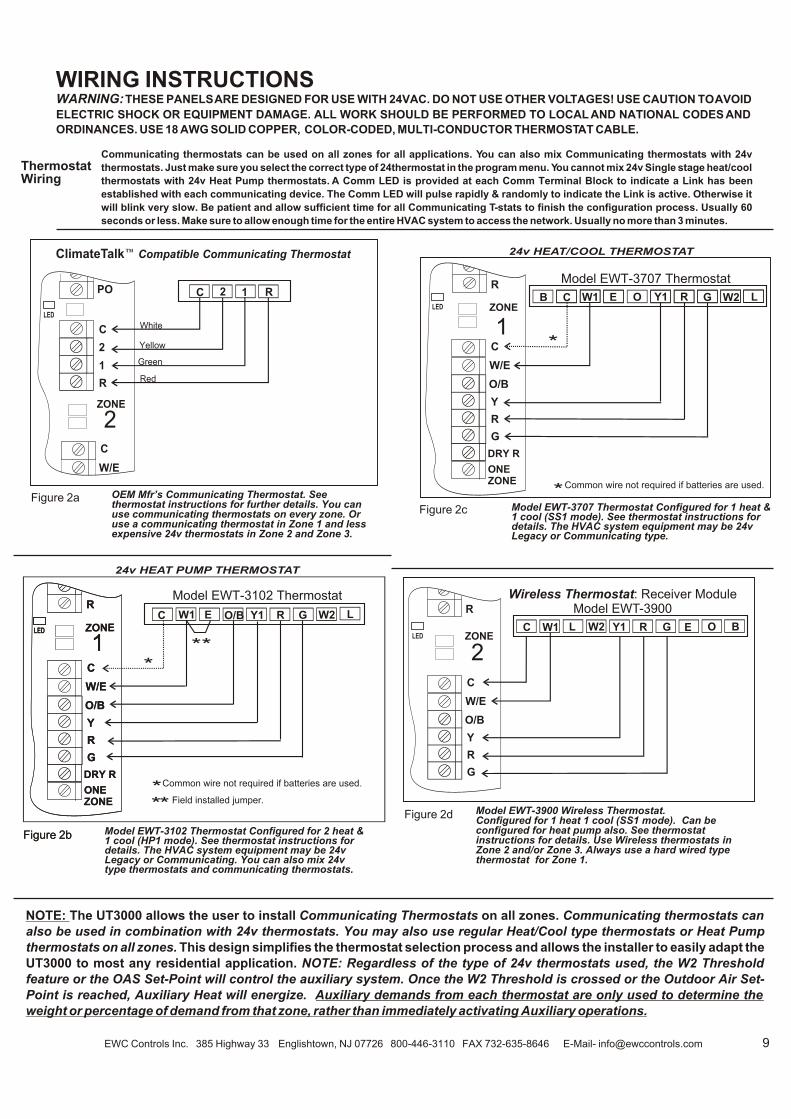
WARNING: THESE PANELS ARE DESIGNED FOR USE WITH 24VAC. DO NOT USE OTHER VOLTAGES! USE CAUTION TO AVOID
ELECTRIC SHOCK OR EQUIPMENT DAMAGE. ALL WORK SHOULD BE PERFORMED TO LOCAL AND NATIONAL CODES AND
ORDINANCES. USE 18 AWG SOLID COPPER, COLOR-CODED, MULTI-CONDUCTOR THERMOSTAT CABLE.
ThermostatWiring
WIRING INSTRUCTIONS
Model EWT-3707 Thermostat Configured for 1 heat & 1 cool (SS1 mode). See thermostat instructions for details. The HVAC system equipment may be 24v Legacy or Communicating type.
Figure 2c
Communicating thermostats can be used on all zones for all applications. You can also mix Communicating thermostats with 24v
thermostats. Just make sure you select the correct type of 24thermostat in the program menu. You cannot mix 24v Single stage heat/cool
thermostats with 24v Heat Pump thermostats. A Comm LED is provided at each Comm Terminal Block to indicate a Link has been
established with each communicating device. The Comm LED will pulse rapidly & randomly to indicate the Link is active. Otherwise it
will blink very slow. Be patient and allow sufficient time for all Communicating T-stats to finish the configuration process. Usually 60
seconds or less. Make sure to allow enough time for the entire HVAC system to access the network. Usually no more than 3 minutes.
Figure 2d
NOTE: The UT3000 allows the user to install Communicating Thermostats on all zones. Communicating thermostats can
also be used in combination with 24v thermostats. You may also use regular Heat/Cool type thermostats or Heat Pump
thermostats on all zones. This design simplifies the thermostat selection process and allows the installer to easily adapt the
UT3000 to most any residential application. NOTE: Regardless of the type of 24v thermostats used, the W2 Threshold
feature or the OAS Set-Point will control the auxiliary system. Once the W2 Threshold is crossed or the Outdoor Air Set-
Point is reached, Auxiliary Heat will energize. Auxiliary demands from each thermostat are only used to determine the
weight or percentage of demand from that zone, rather than immediately activating Auxiliary operations.
24v HEAT PUMP THERMOSTAT
Figure 2b
* Field installed jumper.
Figure 2a
24v HEAT/COOL THERMOSTAT
C O/BE LW1 W2Y1 R G
Model EWT-3102 Thermostat
**C O BELW1 W2 Y1 R G
Wireless Thermostat: Receiver ModuleModel EWT-3900
*
Common wire not required if batteries are used.*
Model EWT-3900 Wireless Thermostat.Configured for 1 heat 1 cool (SS1 mode). Can be configured for heat pump also. See thermostat instructions for details. Use Wireless thermostats in Zone 2 and/or Zone 3. Always use a hard wired type thermostat for Zone 1.
*
OEM Mfr’s Communicating Thermostat. See thermostat instructions for further details. You can use communicating thermostats on every zone. Or use a communicating thermostat in Zone 1 and less expensive 24v thermostats in Zone 2 and Zone 3.
C
W/E
Y
R
G
ONEZONE
O/B
1ZONE
DRY R
R R
Model EWT-3102 Thermostat Configured for 2 heat & 1 cool (HP1 mode). See thermostat instructions for details. The HVAC system equipment may be 24v Legacy or Communicating. You can also mix 24v type thermostats and communicating thermostats.
C OB E LW1 W2Y1 R G
Model EWT-3707 Thermostat
*
*Common wire not required if batteries are used.
C
W/E
Y
R
G
ONEZONE
O/B
1ZONE
DRY R
R
LED
LED LED
ZONE
2
C
R
2
1
C 2 1 R
ClimateTalk™ Compatible Communicating Thermostat
C
W/E
PO
LED
White
Yellow
Green
Red
Figure 2b
C
W/E
Y
R
G
ONEZONE
O/B
1ZONE
DRY R
R
LED

10
The UT3000 panel was designed to be easy to wire up and operate.
We have provided several typical field wiring diagrams to review.
Your actual field wiring may vary. In full communicating mode, 4
wires are all that is required from each thermostat and to the HVAC
system. The UT3000 will “Talk” to the HVAC system and “Talk” to
the thermostats in order to automatically setup and start operating
the HVAC system. In 24volt mode, you can program the UT3000 to
operate the type of HVAC system you are installing. Either way, the
UT3000 allows you to Plug & Play or Program & Play!
Four wires are all that is required to each
component. Plug & Play
System Wiring
Communicating Dual Fuel or Standard
Heat Pump System
Standard Heat Pumpwith “O” TypeReversing Valve
EWC Controls Inc. 385 Highway 33 Englishtown, NJ 07726 800-446-3110 FAX 732-635-8646 E-Mail- [email protected]
Figure 3a
Figure 3b
Figure 3d
Typical heat pump system wiring with either
Electric or Fuel Backup heat. Applies to air
cooled or geothermal HVAC systems.
Program& Play
TYPICAL BOILERcontrol circuit
or HYDRONIC
CIRCULATORcontrol
terminal block
ExistingBoiler withNew A/C
You may have a new Communicating A/C unit but still want to use your Old Boiler as the Heating system.Simply connect the T&T circuit from your boiler control panel to the Rh and W1/B terminals on the UT3000 and your done. Plug & Play
CommunicatingAIR HANDLER
OR FURNACE
CommunicatingOUTDOOR
HEAT PUMP
2
1
C
R
2
1
C
R
W2/E
W1/B
SYSTEMSYSTEM
RH
RC
O
Y
G
RC/RH LINKRC/RH LINK
UT3000
C
2
1
C
R
SYSTEM
Air Handlerwith ElectricBackup Heat
or Fossil Fuel Furnace
HEAT PUMP1 STAGE
X / W
O
Y
C
R
W2
W1
Y
G
R
C
W2/E
W1/B
SYSTEMSYSTEM
RH
RC
O
Y
G
RC/RH LINKRC/RH LINK
UT3000
C
2
1
C
R
SYSTEM
O
Four wires are all that is required to each
component. Plug & Play
Communicating Fuel/Electric System
CommunicatingAIR HANDLER
CommunicatingOUTDOOR
CONDENSING UNIT
2
1
C
R
2
1
C
R
W2/E
W1/B
SYSTEMSYSTEM
RH
RC
O
Y
G
RC/RH LINKRC/RH LINK
UT3000
C
2
1
C
R
SYSTEM
T
T
T
T
To Radiant Floor Loop Control Thermostat
White
Yellow
Green
Red
Figure 3c
Communicating FURNACE
CommunicatingOUTDOOR
CONDENSINGUNIT
2
1
C
R
2
1
C
R
W2/E
W1/B
SYSTEMSYSTEM
RH
RC
O
Y
G
RC/RH LINKRC/RH LINK
UT3000
C
2
1
C
R
SYSTEM
White
Yellow
Green
Red
White
Yellow
Green
Red
Contact EWC Controls Technical Support for assistance on these and other Equipment Wiring Solutions.
C
PO
PCDAMPER
Figure 5d
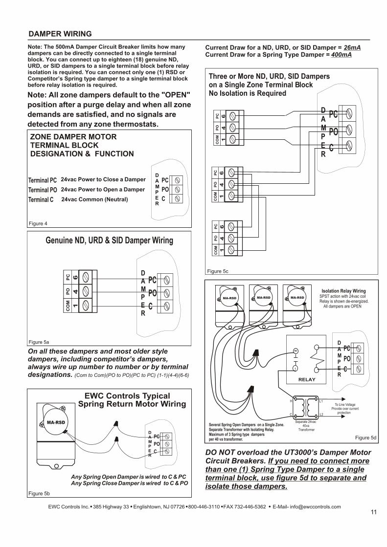
Several Spring Open Dampers on a Single Zone. Separate Transformer with Isolating Relay.Maximum of 3 Spring type dampers per 40 va transformer.
Isolation Relay Wiring SPST action with 24vac coilRelay is shown de-energized. All dampers are OPEN
To Line VoltageProvide over current protection
Separate 24vac 40va Transformer
L1
L2
H
C
NO
C
MA-RSD MA-RSD MA-RSD
RELAY
CO
MP
OP
C
46
1
Note: All zone dampers default to the "OPEN"
position after a purge delay and when all zone
demands are satisfied, and no signals are
detected from any zone thermostats.
24vac Common (Neutral)
24vac Power to Open a Damper
24vac Power to Close a Damper
Terminal C
Terminal PO
Terminal PC
ZONE DAMPER MOTOR TERMINAL BLOCK DESIGNATION & FUNCTION
Note: The 500mA Damper Circuit Breaker limits how many dampers can be directly connected to a single terminal block. You can connect up to eighteen (18) genuine ND, URD, or SID dampers to a single terminal block before relay isolation is required. You can connect only one (1) RSD or Competitor’s Spring type damper to a single terminal block before relay isolation is required.
Figure 4
DO NOT overload the UT3000’s Damper Motor Circuit Breakers. If you need to connect more than one (1) Spring Type Damper to a single terminal block, use figure 5d to separate and isolate those dampers.
Figure 5c
EWC Controls Inc. 385 Highway 33 Englishtown, NJ 07726 800-446-3110 FAX 732-446-5362 E-Mail- [email protected]
DAMPER WIRING
Three or More ND, URD, SID Dampers on a Single Zone Terminal BlockNo Isolation is Required
C
PO
PCDAMPER
.
Figure 5b
.
EWC Controls Typical Spring Return Motor Wiring
Any Spring Open Damper is wired to C & PCAny Spring Close Damper is wired to C & PO
C
PO
PCDAMPER
MA-RSD
C
PO
PCDAMPER
Figure 5a
C
PO
PCDAMPER
Genuine ND, URD & SID Damper Wiring
CO
MP
OP
C
46
1
CO
MP
OP
C
46
1
CO
MP
OP
C
46
1
Current Draw for a ND, URD, or SID Damper = 26mACurrent Draw for a Spring Type Damper = 400mA
On all these dampers and most older style dampers, including competitor’s dampers, always wire up number to number or by terminal designations. (Com to Com)(PO to PO)(PC to PC) (1-1)(4-4)(6-6)

ISOLATING 24vac SHORTS
Dampers not responding and TheUT3000 LED’s are off.
HVAC system not responding andUT3000 LED’s are off.
DETECTING 24vac SHORTS
Check HVAC/UT3000 system transformer supply voltage.Check HVAC/UT3000 system 24vac transformer voltage/Breaker. Test wires for Continuity/Shorts.Check HVAC/UT3000 system wiring for shorts/miswiring.
Check Zone system wiring for shorts/miswiring. Test wires for Continuity/ShortsCheck HVAC system wiring for proper wiring. Check HVAC system for faults Check Zone thermostats for proper connections. Test wires for Continuity/ShortsRefer to Technical Bulletin for correct Setup/Wiring/Program Settings.
Check HVAC system wiring for proper connections. Check HVAC system wiring for shorts/miswiring.Test wires for Continuity/Shorts.Check HVAC System documentation. Check HVAC equipment for faultsRefer to Technical Bulletin for correct Setup/Wiring/Program Settings.
SOLUTIONS
T R O U B L E S H O O T I N G
LCD & LED’s function and HVAC system functions normally but
dampers do not respond.
Check damper motor wiring for proper connections.Check damper motor 24volt & 500mA Breaker. Test wires for Continuity/ShortsCheck damper motor wiring for shorts/miswiring. Test wires for Continuity/ShortsRefer to Page 11 for Damper Wiring.
140mA & 500mA circuit breakers protect the UT3000 and react to a short in the Thermostat/Damper
component field wiring.
CHECK YOUR WIRING
EWC® Controls provides superior toll free Troubleshooting Support for the UT3000 when you are on the job site!
Call 1-800-446-3110 Monday - Friday 8am to 5pm EST. Otherwise call 1-732-446-3110 for information on the UT3000 and other ULTRA-ZONE® products. Visit our web site to download this Technical Bulletin and other related information at www.ewccontrols.com
When calling for Technical Support from the job-site, please have a multi-meter, pocket screwdriver, and wire cutters/strippers on hand.
TECHNICAL SUPPORT
LCD & LED’s do not function and HVAC system does not respond.
LCD & LED’s are not responding properly and HVAC system is
malfunctioning.
LCD & LED’s are responding properly but HVAC system is malfunctioning. Communicating T-stat displays fault
messages.
SYMPTOM
Disconnect the wire(s) from the ‘R’ terminals on the UT3000 thermostat terminal blocks , and the “C/PO/PC’’ terminals on the UT3000 damper motor terminal blocks. Restore power. If the short is no longer present, Ohm out the thermostat and damper field wiring for continuity, shorts to common and/or shorts to earth ground. Replace or repair wires as necessary. Restore power.
SOLUTIONS: Remove 24vac power from UT3000 and allow F1 circuit breaker to cool! Find and repair short(s) in damper and/or thermostat field wiring. Restore 24 vac power.
If 24vac short has occurred, 24vac will be present at the UT3000 24v Input terminals R & C; but 24vac will not be present at any Thermostat R&C.
SYMPTOM: Entire Panel or a Single Zone appears to be dead!
When the 2.5A breaker is tripped it will get hot to the touch and none of the panel LED’s will illuminate. The
LCD will also cease to function. To reset the breaker, locate the short by removing each hot wire connected to the
panel, one at a time. When the shorted wire is removed, the panel will resume normal functions. Now you must
repair or replace the shorted wire. If one or more 140mA or 500mA breakers trip, only the device(s) connected to
that block will be affected. Remove each hot wire connected to that block until the voltage is restored. Find and
repair the short before re-connecting the wires. If there is a short between the Data 1 & 2 wires or if the Data wires
are shorted to 24v or earth ground, the Communicating thermostat on that zone will alert you by displaying “Call
for Service”. If no communicating thermostat is connected and a short occurs on the 24v wires, that zone will not
function. Find and repair the short using the methods described above.
EWC Controls Inc. 385 Highway 33 Englishtown, NJ 07726 800-446-3110 FAX 732-446-5362 E-Mail- [email protected]
Detecting 24v shorts to common or shorts to earth ground
Forward
Back
When Troubleshooting, Simultaneously Press the Back & Forward buttons for 1 second to Bypass any Active Time Delay.
Time Delay is Active and won’t allow Heat or Cool to Function.


