Download - 2015 porfolio

Alexis LockeMarketing Porfolio

BrochuresDV1- 2013

DV1 continued..
1 2
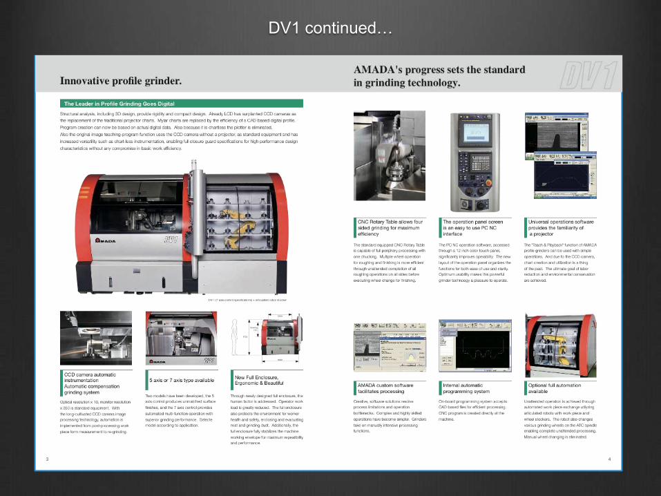
From Optical to Graphical.
AMADA brings the next generation in profile gri ndi ng.
Part qualific
a
t ion is ful ly aut oma t ed due to aut oma t ic ima ge me asur ement with a CCD camera. Part tolerance can be
automatically measured and compensated. The issue of projector based, eye ball inspection variability is eliminated. Ultra fin
e
workpiece can be automatically and repeatably inspected with great effici ency .
With optional articulating robot & stocker, automatic wheel change and workpiece loading, optimal unattended through put is
provided.
This innovation has enabled unmatched productivity in profile gr indi ng. No t sur pr isi ngl y, it has received the award of The Most
Innovative Machine in the grinder division at the prestigious European exhibition Germany AMB2008.
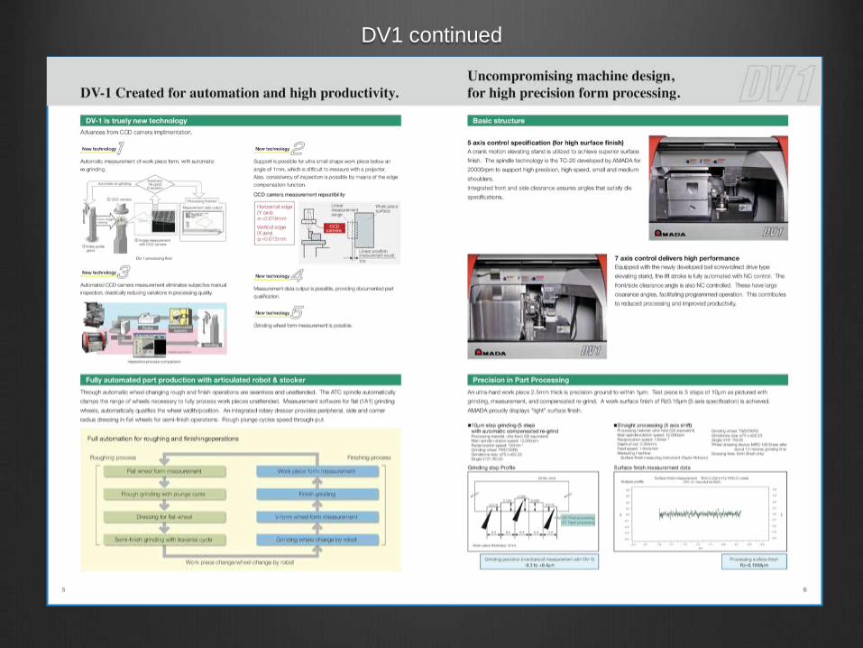
If you use two machines for one worker, our optical profile gr inder GL S- 5P/ 5T r equires manual form measurement and program
correction causing machine idle time. In contrast, DV-1 can perform this task automatically, resulting in shorter lead times. This
achieves improved productivity.
Ultra precision metal press punch
Operation 3
Programmedcorrection
GLS-5P/5T
DV-1
Idle tim e occurs
S horten ed lead tim e!
*Varies according to level of proficiency.
Firs t
m achin e
Operation 1
Grinding
Automatic
S eco n d
m achin e
Operation 1
Grinding
Automatic
Operation 2
Forminspection
Manual
Operation 3
Programmedcorrection
Operation 2
Forminspection
Manual
Operation 4
Re-grinding
Automatic
Operation 4
Re-grinding
Automatic
Firs t
m achin e
Operation 3
Programmedcorrection
Operation 2
Forminspection
Operation 4
Re-grinding
Operation 1
Grinding
Automatic
Operation 3
Programmedcorrection
Operation 2
Forminspection
Operation 4
Re-grinding
Operation 1
Grinding
Automatic
S eco n d
m achin e
Compact, chartless, and fully automatic, 3rd generation profile grinder
Multi-Processing Capability
Comparing Optical Grinding to Graphical Grinding
DV-1 (5 axis control specifica t ions)
DV1 continued…
DV1 continued

DV1 continued…

DV1 continued…
9 10
Machine Specific
a
t ion NC control Specifica t ion
Floor layout DV-1 stand alone specific
a
t ion
Software
DV-1 software (application for PC)Conversational
microsoftware, etc.
Standard
functions
Image teaching playbackWheel data recording
function
Chartless measurementFixture recording
function
Processing simulation displaySimple S command
(7-speed)
Work piece standard
measurementWarm up setting
Processing actual
performance display
Wheel position measurement
(wheel transcription form
measurement)
Automatic work piece form
measurement/correction
processing software
Optional
functions
Rough grinding cycle Taper interpolation
R-forming dress softwareSimple circuler
interpolation
Outside auto programing
software ASSIST DV*4Repeat cycle
Run hour display
function
*4 Not compatible with WAPS WIN.
Specific
a
t ions
Item Unit 5 axis control specif cation 7 axis control specif cation
Projector
Screen size mm 12 inch LCD (CCD view range 0.5 x 0.4)
Magnific
a
t ion Optical magnific
a
t ion x10/ Mo ni tor ma gni fica
t
i on x350
Lighting W Tapering lighting 150
Table
Working surface mm ø115 (Round table)
Distance from the table top to focus point mm 200
Maximum loading weight kg 20 (Work piece+ Fixture+ Chuck)
Linear axis
Travel
Traverse feed (X axis) mm 300
Cross feed (Y axis) mm 250
Vertical feed (Z axis) mm 80
Feedrate
Rapid traverse (G00) mm/min XY: 2000, Z: 500
Linear Interpolation
(G01)mm/min XY: 0.1 – 1000, Z: 500
Jog feed mm/min XY: 2000, Z: 500
Minimun input increment mm 0.0001
Position
detection/
Scale resolution
XY axes µm Full-closed/0.05
Z axis Semi-closed
Rotary axis B
Travel deg 360
Feedrate
Rapid traverse (G00) deg/min 1000
Linear Interpolation
(G01)deg/min 0.1 – 1000
Jog feed deg/min 1000
Minimun input increment deg 0.0001
Position detection/Scale resolution deg Full-closed/±5
Wheel
spindle
Whreel size (outer diameter x width x hole diameter) mm ø65 – 100 x 4 – 6 x ø22.23 ø120 – 180 x 3 – 10 x ø31.75
Spindle Nose mm ø25.4 1/4 Taper
Spindle speed min-1 2000 – 20000 (TC-20) 600 – 6000 (TS-6)
Wheel
head
Reciprocating
axis
Recprocating slide stroke (W axis) mm 0 – 80*1
Drive system Crank Ball screw
Reciprocation speed min-1 30 – 400 (In case of 10st)*2 30 – 200 (In case of 15st)*2
Jog feed mm/min 2000
Minimun input increment mm 0.0001
Position detection Semi-closed
Relief angle
Travel
Radial relief angle
(V axis)deg -1 – 2 (Manual operation) -1 – 15 (NC control)
Axial relief angle
(A axis)deg ±3 (Manual operation) ±8 (NC control)
Rapid traverse (G00) deg/min 72
Jog feed deg/min 72
Minimun input increment deg 0.0001
Position detection Semi-closed
Motor
Wheel spindle kW-P 1.5-4 (TC-20) 1.5-4 (TS-6)
X/Y axes kW 0.75
Z axes kW 0.5
B axis kW 0.05
Reciprocating axis (W axis) kW 1.8 1.0
A axis kW 0.05
V axis kW 0.05
Automatic lubrication W 4
Power capacity kVA 13
Machine size (width x depth x height) mm 1630 x 2370 x 1717
Machine weight kg 4000
*1 Length that can be processed will vary depending on the setting of relief angle.
*2 There is limitation depending on the reciprocation stroke.
Profil
e
gr inder s lineup
DV-1 GLS-5P GLS-5T
Graphical profile gr inder Optical profile gr inder s
Floor layput/Robot Stocker Specific
a
t ion
R830
70
010
00
FL
1717
1630
1230
18
05
56
570
0
Front viewTop view Side view
(Units: mm)
Multi-axis robot stocker specific
a
t ion
Control unit model FANUC Series 180i-MB
Number
of control
axis
5 aixs control specifica t ionTable X, Y, Table vertical Z, reciprocation W
Work piece rotay B
7 axis control specifica t ionTable X, Y, Table vertical Z, reciprocation W
Work piece rotary B, radial relief V, axial relief A
Standard
functions
12' color LCD (touch panel) Manual reference return
PC NC (O/S Windows XP) Memory-type pitch error compensation
CNC screen display function Feedrate override 0 to 200%
Wheel spindle infin
i
tel y var iabl e- speed
drive (inverter control)Tape memory 40m (16kB)
Simple S command (7-speed) Registerable programs 63
Reciprocation 20-speed (servo control) Total tool offset pairs 32
Circuit breaker (30mA) Tool length compensation
Auto power off Rapid speed override
AC100V outlet (2P-1 outlet) Warm up timer (daily timer)
3 manual handles
(5-spindle control specifica t ion:
Common to X axis, Y axis, Z/B axis)
(7-spindle control specifica t ion:
X axis, Y axis, Z/W/B/A/V axis)
Memory card I/O
Handle magnific
a
t ion rat io Of f, x1, x10, x100 Table setup function
Optional
functions
Additional memory
(80, 160, 320, 640, 1280m)Run hour and parts count display
Additional registerable programs
(125, 200, 400)Cycle time stamp function
Additional tool offset pairs (64, 99, 200, 400) Automatic corner override
Weekly timer
I/O interface
LAN connection (additional Ethernet
function/connector for the PC part) *3
*3 Device for LAN connection is added. The network connection for the PC part should be set by customer.
Item Unit Specific
a
t ion Note
Robot
Robot Manufacturer: FANUC
Number of controled axis axis 6
Maximum travel mm 892
Maximum delivery weight kg 5 including robot hand
Machine weight kg 29
Stocker
Maximum number of stocked pallets pcs 12 4 pallet x 3
Maximum number of stocked wheel fla
n
ge pcs 4 4 tools x 1
Maximum work piece size mm ø115 x 90 from pallet top surface Pallet diameter ø80 is available
Maximum wheel size mm ø75 – 85 x 4 to 6

Magazine Print & Online Ads

Magazine Print & Online Ads

Magazine Print & Online Ads

Magazine Print & Online Ads
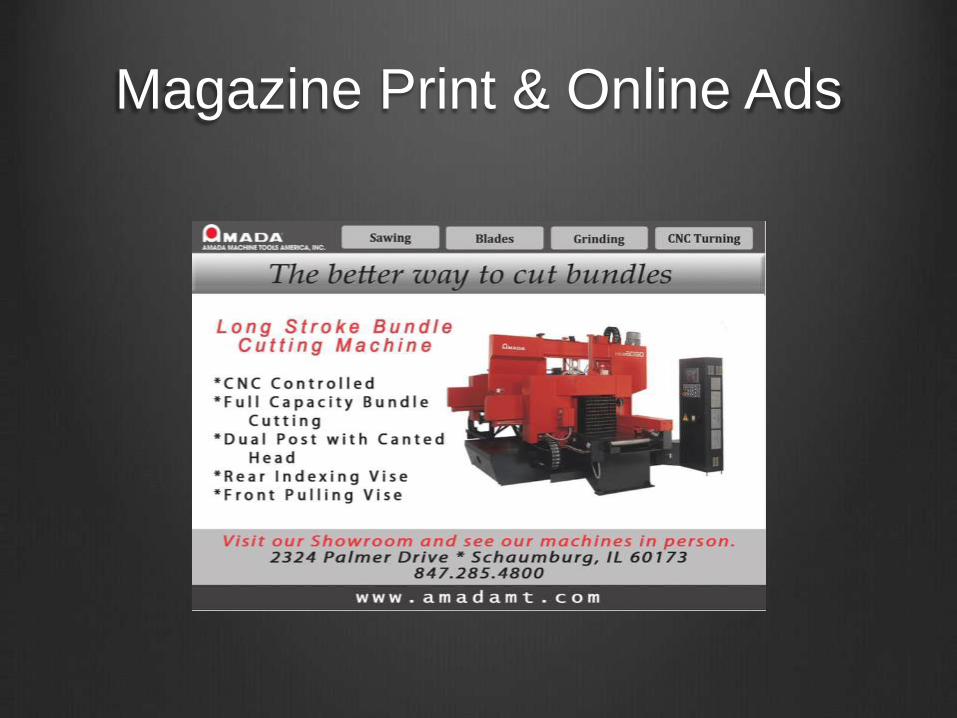
Magazine Print & Online Ads
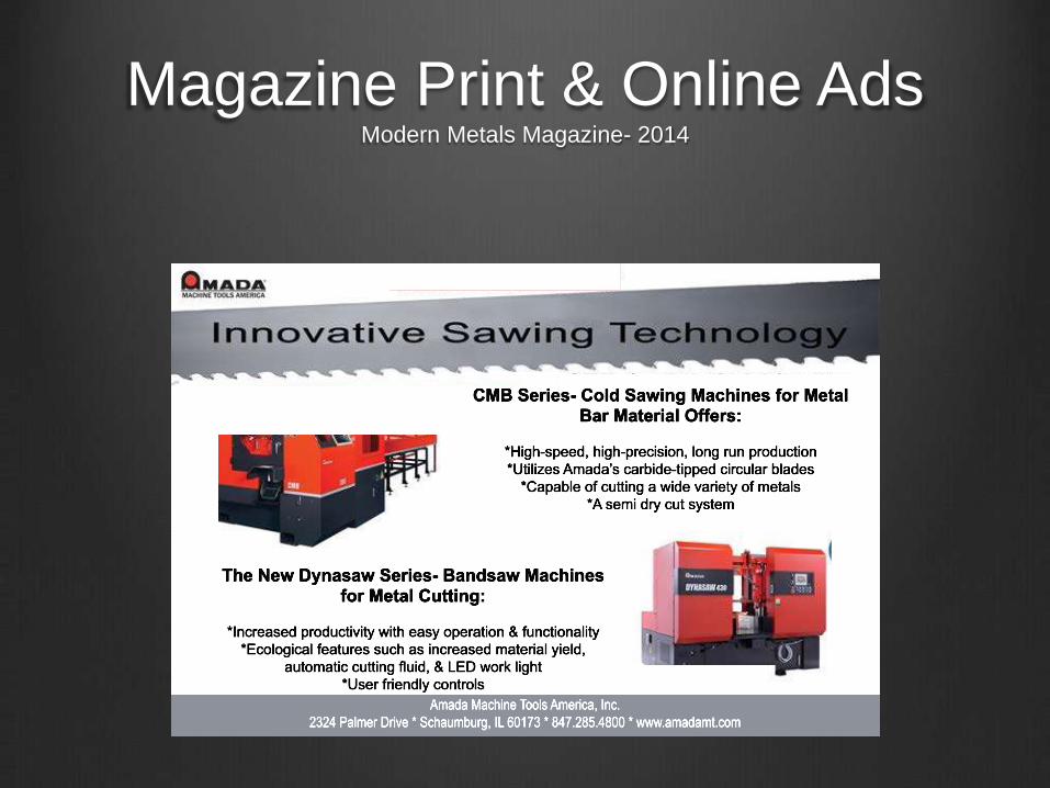
Magazine Print & Online AdsModern Metals Magazine- 2014

Magazine Print & Online Ads

Magazine Print & Online Ads

Magazine Print & Online Ads

Sales Tools2014
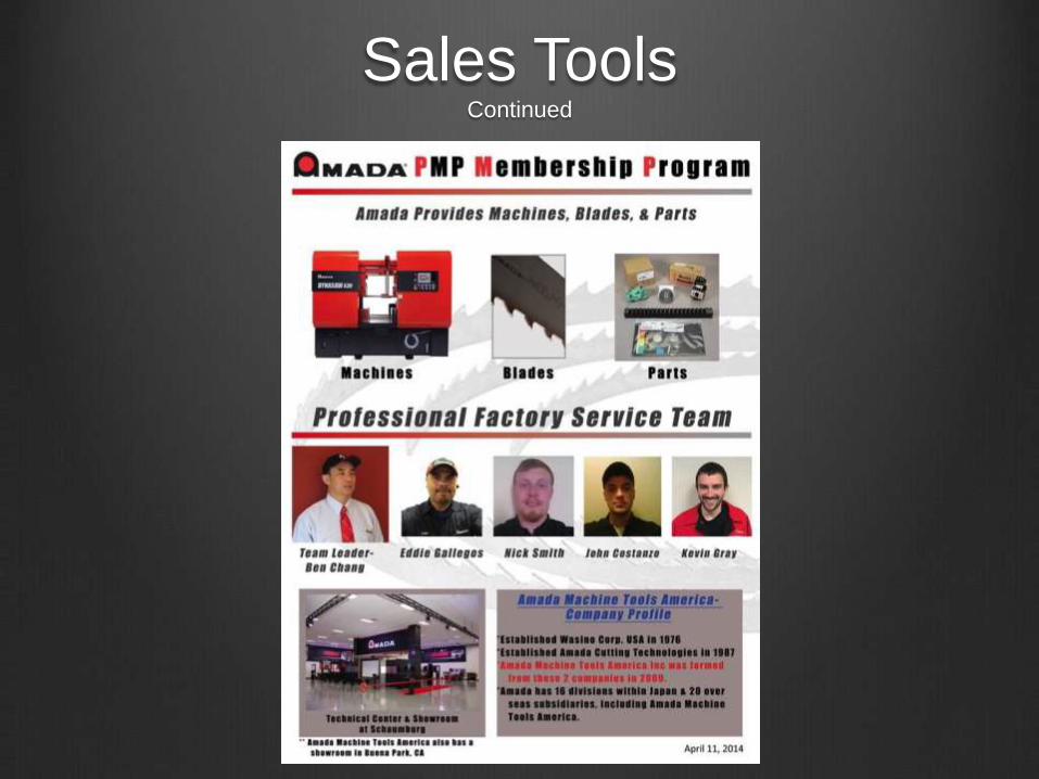
Sales ToolsContinued

Sales Toolscontinued

Open House InvitesDigital & Physical

Open House Invitescontinued