Texas Commission on Environmental Quality Appendix PSampling Procedures Manual
Revision No.: One 1/2003P-1
APPENDIX P
COOLING TOWER MONITORING
General
Cooling tower monitoring describes the characterization of volatile organic air pollutants that arecapable of being air-stripped from a water matrix. While generic or indicator monitoring may berequired to identify the existence of volatile organic compound (VOC) emissions, speciatedcompound characterizations may also be required in some instances to characterize the specificcompounds present.
Historically, a method for cooling tower water characterization was developed for use by El PasoProducts Company in the early 70's. This method utilized a dynamic or flow-through system for airstripping a sample of the water and analyzing the resultant off-gases for VOCs using a commonflame ionization detector (FID) analyzer, and has been the popular choice in Texas for many years.The El Paso Products method, however, has been overshadowed nationally by the use of purge andtrap analysis of water samples utilizing gas chromatography and/or mass spectrometry techniques.While direct water analysis has been shown to be effective for cooling tower measurements ofheavier molecular weight organic compounds with relatively high boiling points, Texas Commissionon Environmental Quality (TCEQ) has determined that this approach may be ineffective for captureand measurement of volatile organic compounds with lower boiling points, such as ethylene,propylene, 1,3-butadiene, and butenes. VOCs with a low molecular weight and boiling point aregenerally lost in the sample collection step of purge/trap type analyses. Consequently, TCEQrequires that the air stripping method presented in this manual be used for cooling tower and otherapplicable water matrix emission measurements of VOCs with boiling points below 140 oF. Specificprocedures for cooling tower sampling and analysis for VOCs with boiling points of 140 oF andgreater must be submitted to TCEQ for approval on a case-by-case basis.
Texas Commission on Environmental Quality Appendix PSampling Procedures Manual
Revision No.: One 1/2003P-2
Air Stripping Method (Modified El Paso Method) for Determination of Volatile Organic Compound Emissions from Water Sources
1.0 Principle and Applicability
1.1 Principle. A continuous stream of cooling water, process water, or wastewater issupplied via a hard pipe or direct interface to an air stripping column apparatus for analysis.Air flowing countercurrent to the water strips volatile organic compounds from the water foranalysis. Some gases may flash from the water immediately upon entering the apparatus andthese gases are trapped and mixed with the air stripped compounds. The concentration ofthe air stripped compounds combined with the flashed gases is determined at the apparatusair outlet by a suitable detector and/or by sampling. Concentrations of air strippedcompounds in the air exhaust, along with the air and water flow rates, are used to determineconcentrations of strippable volatile compounds in the water. A FID analyzer is used todetermine a value of “combined” or “total” strippable volatile organic compounds. Samplesmay also be collected in sample canisters for shipment to analytical laboratories forspeciation of air contaminants. A gas chromatograph (GC) with an appropriate detector maybe used to determine specific stripped species.
1.2 Applicability. This method is applicable to cooling tower water systems and may beapplicable to qualitative and/or quantitative measurements on other sources such as APIseparators and wastewater systems.
2.0 Sensitivity
2.1 The sensitivity of this method for the onsite analysis by FID analyzer is typically 0.1to 0.5 part-per-million, by volume (ppmv) methane in the stripped air, depending on thespecific analyzer. The sensitivity of the GC speciation analysis will vary depending on thedetector used. Detection limits as low as 2 - 50 part-per-billion, by volume (ppbv) in thestripped air may be possible with the use of a gas chromatograph equipped with a massspectrometer (GC/MS).
2.2 FID Response. Response factors are not used to correct the total VOC measurement byFID analyzer. Speciation analysis of the VOCs present in the stripped gas would be requiredto correctly apply any proportioned response factor to the total VOC measurement, in whichcase, the results should be calculated from the speciated analysis rather than the total VOCresults. Some chemicals, such as formaldehyde, will not respond well on a FID, havingparticularly high response factors and, therefore, high detection limits. The total VOC
Texas Commission on Environmental Quality Appendix PSampling Procedures Manual
Revision No.: One 1/2003P-3
procedure by FID should not be used on sources for which any potential targeted VOC hasa response factor multiplier greater than 2 relative to methane. Such sources must either besampled following the speciation procedure in Section 6.2, or an alternative detector,approved by the TCEQ, must be used in the total VOC procedure in Section 6.1. Alternativesampling and analysis procedures such as sorbent tube sample collection and analysis byhigh performance liquid chromatography (HPLC) are subject to TCEQ approval.
3.0 Equipment and Materials
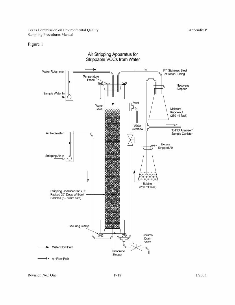
3.1 Air stripping apparatus. An air stripping apparatus as presented in Figure 1 and meetingthe following requirements:
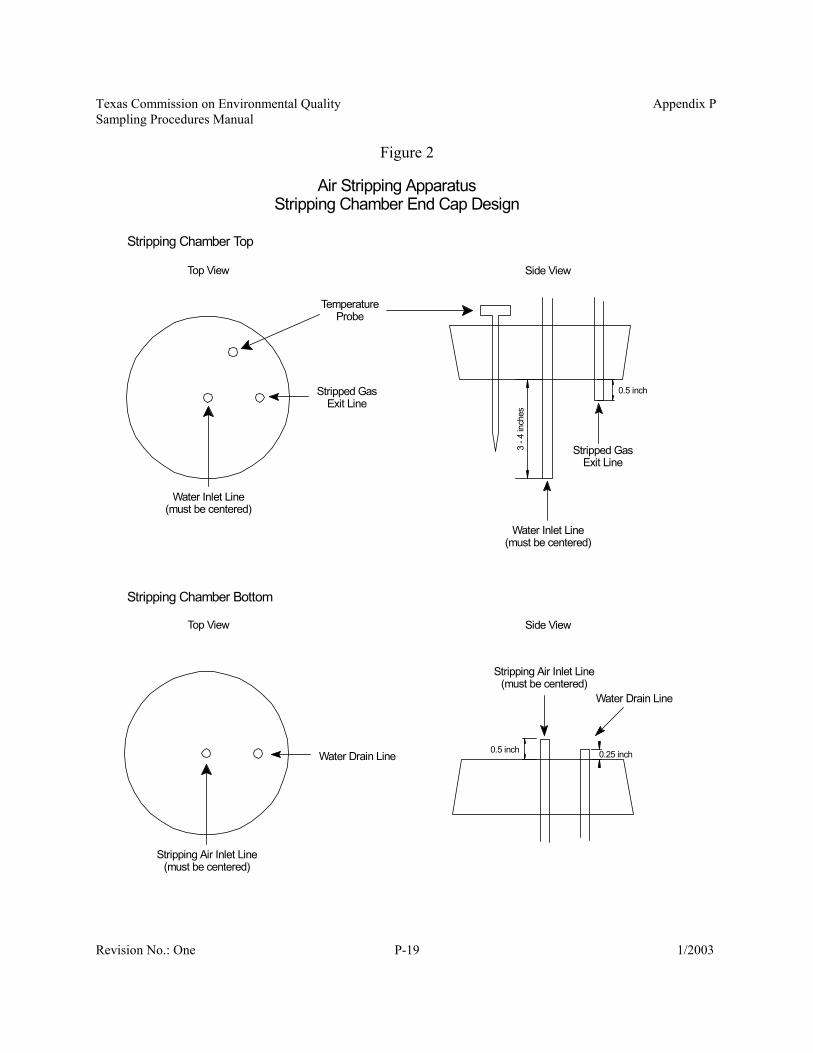
3.1.1 The stripping chamber shall be a cylinder 36 inches in length with an internaldiameter of 3 inches, and constructed of clear, heavy-walled glass.3.1.2 The stripping chamber packing material shall be beryl saddles between 6 to 8millimeter size. The depth of the packing material will be 26 inches.3.1.3 The end caps of the stripping chamber must meet the dimensions specified inFigure 2. Neoprene stoppers are recommended; however, securing clamps will berequired to prevent leakage. Black rubber stoppers are not allowed due to thepotential absorption and release of organic compounds. Alternative designs for theend caps, such as customized threaded plastic caps with Neoprene gaskets, areacceptable provided the materials used are non-reactive with the sample matrix ortarget compounds, and the end caps meet the specifications in Figure 2. The tip ofthe water sample inlet line is intentionally left 5 to 6 inches above the water level inthe stripping chamber to help accelerate the response of the system as some VOCswill be released immediately as the water falls into the chamber. 3.1.4 Tubing used in the air stripping apparatus for transporting gas and water shallbe 1/4 inch stainless steel or Teflon material. Stainless steel or Teflon 1/4 inchtubing of minimal length shall be used to route water sample from the sample tap tothe air stripping apparatus. The water sample tubing from the sample tap shall notbe more than 50 feet in length. 3.1.5 Drying agents, such as Drierite™, for removing moisture from the stripped airstream before analysis by FID or collection in sample canisters are strictly prohibitedto prevent loss of VOCs to the drying agents. An empty, clear-glass flask is used asa knock-out to remove some of the moisture in the stripped air stream, but gasexiting the stripping chamber will essentially be at saturated moisture for the ambientconditions. Different styles of knockout flasks are acceptable; however, the flaskmust be clear-glass and 500 ml or less in size. Some FID analyzers may not be ableto monitor for prolonged periods under such conditions and intermittent monitoringmay be required.3.1.6 A T-union with one leg leading to a bubbler must be included as shown inFigure 1. Excess air not drawn into the analyzer probe or sample canister is vented
Texas Commission on Environmental Quality Appendix PSampling Procedures Manual
Revision No.: One 1/2003P-4
through the bubbler and serves to indicate that sufficient flow has been established.This is to assure that the sample is only from the stripped air and is not drawing inany external air. With the bubbler in place, care must be taken not to pull water intothe FID analyzer or sample canister.3.1.7 Gas bubble formation in the water rotameter can sometimes result from thepressure drop across the water rotameter control valve. Significant gas bubbles caninterfere with accurate measurement of the sample water flow to the strippingchamber. A suggested possible solution to this problem is to place a control valvedownstream of the water rotameter. By opening the rotameter to the fully openposition or using a non-metering rotameter, and controlling the flow with the valveafter the rotameter, the pressure drop occurs after the rotameter and bubble formationmay be minimized. This approach may require a fine-adjusting control valve toachieve the flow rate control desired, and the tester must be certain that the waterrotameter can withstand the pressure in the water source being sampled.Note: The TCEQ air stripping apparatus design is based on the apparatus designedby El Paso Products Company of Odessa, Texas (see Reference 9.1)
3.2 Flame Ionization Detector (FID) Analyzer. Analyzers with analog type readouts andthose normally used for leak detection are generally not appropriate for this method becausesuch instruments are designed for much higher concentration measurement than would beexpected in the air stripping apparatus effluent. FID analyzers used in conjunction with themethod must:
3.2.1 be a digital readout type, readable to 0.1 ppmv.3.2.2 be able to meet the calibration requirements specified in Section 4.1.3.2.3 have a sampling rate less than 2000 ml/min since the stripping air flow rate is2500 ml/min and an excess air flow is required.
3.3 Gases for Air Stripping Apparatus Operation and FID Analyzer Calibration.3.3.1 Zero Calibration Gas and Stripping Air. Air, certified to contain less than orequal to 0.1 ppmv of total hydrocarbon (THC).3.3.2 High-Level Calibration Gas. Cylinder gas standard of methane in air, certifiedby the manufacturer to be within ±2% of the specified concentration. If the sampleconcentration of VOCs in the stripped gas is less than 10 ppmv as methane, the spangas calibration standard shall be 10 ppmv methane. Higher concentration spancalibration standards may be necessary for some sources. If a higher calibrationstandard is required, select a high-level concentration such that the measured sampleconcentrations are between 10% and 100% of the high-level calibration gasconcentration.
3.3.3 Mid-Level Calibration Gas. Cylinder gas standard of methane in air, certifiedby the manufacturer to be within ±2% of the specified concentration. The mid-levelcalibration gas concentration shall be between 20% and 50% of the high-level
Texas Commission on Environmental Quality Appendix PSampling Procedures Manual
Revision No.: One 1/2003P-5
calibration gas concentration. (See note under 4.1.2.4.)3.3.4 Certified gases must be used within the manufacturer’s specified shelf life, orrecertified upon expiration.3.3.5 Subject to TCEQ approval, calibration gas standards other than methane maybe used for sources that have only one or a predominate potential VOC present in thewater matrix.
3.4 A gas chromatograph equipped with appropriate detector(s) for laboratory or fieldspeciation of the specific organic components.
3.5 Sample canisters. Internally passivated stainless steel canisters for collection of airstripped samples for speciation analysis by GC. Sample canisters shall meet all requirementsof Compendium Method TO-14A (US EPA Compendium for Determination of ToxicOrganic Compounds in Ambient Air, EPA Document Number 625/R96/010B). Each samplecanister shall be equipped with a) a vacuum gauge and b) either a needle valve for manuallyregulating flow rate or an automated flow regulator (i.e., a critical orifice or mass flowcontroller).
3.5.1 Tedlar™ bags may be used in place of stainless steel sample canisters, if thefollowing provisions are met:
3.5.1.1 Bag samples must be analyzed according to Title 40 Code of FederalRegulations, Part 60, Appendix A, Method 18.3.5.1.2 The recovery study for bag sampling in Section 8.4.2 of Method 18must be performed for all the target compounds. The recovery study isperformed by metering a known volume of zero air through a water blankstripping apparatus into the Tedlar™ bag and then spiking the bag with thetarget compounds. This step checks not only the potential loss of compoundsdue to the permeability of the Tedlar™, but also loss due to condensedmoisture in the bag. Percent recovery for each target compound must bebetween 70 - 130%, or Tedlar™ bags are not acceptable for samplecollection. When Tedlar™ bags are acceptable, as specified in Method 18,analysis results for target compounds must be corrected for the percentrecoveries.3.5.1.3 Tedlar™ bags must be new and unused. 3.5.1.4 Tedlar™ bags shall be checked for leaks and contamination asdescribed in Method 18, Section 16.1.3.2. 3.5.1.5 Samples in Tedlar™ bags must be analyzed within 72 hours ofcollection. Recovery study bags must be stored for the same period of timeas the sample bags.
4.0 Calibration.
4.1 FID Analyzer Calibration.
Texas Commission on Environmental Quality Appendix PSampling Procedures Manual
Revision No.: One 1/2003P-6
4.1.1 Initial/Periodic Instrument Performance Evaluation. Perform the calibrationprecision and response time tests as described in Sections 8.1.2 and 8.1.3 of Method21 in 40 CFR 60, Appendix A. 4.1.2 Calibration Procedure.
4.1.2.1 Warmup period. Follow manufacturer’s recommendations.4.1.2.2 Zero calibration. Introduce the zero gas (or stripping air) to the FIDanalyzer. Calibrate the analyzer to read 0.0 ± 0.2 ppmv. 4.1.2.3 High-level calibration. Introduce the high-level calibration gas (10ppmv methane) to the FID analyzer. Calibrate the analyzer to read within ±5.0% of the calibration gas certified value. 4.1.2.4 Mid-level calibration check. Introduce the mid-level calibration tothe FID analyzer. The FID analyzer response on the mid-level calibrationgas must agree within ± 5.0% of the calibration gas certified value. Note:The mid-level calibration step is optional if the VOC emissionsdetermination is based solely on the results of the GC speciation analysis ofthe sample canister or Tedlar™ bag samples.
4.2 GC Calibration. 4.2.1 GC analysis by Method 18.
4.2.1.1 Follow the calibrations procedures described in Sections 8.2.1.5.2.1and 10.0 in Method 18.4.2.1.2 Alternative procedure. If a facility or laboratory is performing thesame analysis on samples collected by this method on a daily basis, then thecalibration and standardization procedures in Section 10.0 of 40 CFR 60,Appendix B, Performance Specification (PS) 9, may be used. The initial andperiodic calibrations must satisfy all the requirements of Method 18 Sections8.2.1.5.2.1 and 10.0, as well as those in Section 10.0 of PS9.
4.2.2 GC analysis by Compendium Method TO-14A (US EPA Compendium forDetermination of Toxic Organic Compounds in Ambient Air, EPA DocumentNumber 625/R96/010B)
4.2.2.1 Follow the appropriate calibration procedures described in Section 10of TO-14A for the selected detector(s) in the GC system.
4.3 Air rotameter calibration. 4.3.1 Calibrate the air supply rotameter system with a dry gas meter, soap filmflowmeter, or similar direct volume measuring device with an accuracy of ± 2percent. 4.3.2 Operate the rotameter at 2500 cc/min for at least three calibration runs for 10minutes each. When three consecutive calibration flow rates agree within ± 5percent, average the three flow rates. 4.3.3 If the average measured calibration flow rate agrees within ± 5% of therotameter reading, the rotameter is acceptable. If the difference between the
Texas Commission on Environmental Quality Appendix PSampling Procedures Manual
Revision No.: One 1/2003P-7
rotameter reading and the measured calibration flow rate exceeds ± 5%, then remarkthe rotameter to the calibrated flow rate.4.3.4 Perform the rotameter calibration before the first field test and semiannually,thereafter.
4.4 Water rotameter calibration.4.4.1 Calibrate the water rotameter with a Class A volumetric flask, graduatedcylinder, or similar container with a volume known to ± 2% accuracy and capableof holding a volume at least 4 times the calibration flow rate (i.e., a 500 mlvolumetric flask to calibrate the rotameter at 125 ml/min.) 4.4.2 Operate the water rotameter at 125 ml/min while filling the container. Recordthe time required to fill the container and calculate the actual flow rate based on thecontainer volume and time required to fill the container. Repeat until threeconsecutive flow rates agree within ± 5% of the mean. 4.4.3 If the average measured calibration flow rate agrees within ± 5% of therotameter reading, the rotameter is acceptable. If the difference between therotameter reading and the calibration flow rate exceeds ± 5%, then remark therotameter to the calibrated flow rate.4.4.4 Perform the rotameter calibration before the first field test and semiannually,thereafter. 4.4.5 Alternatively, a Class A volumetric flask or graduated cylinder may be used inthe field test to collect water at the stripping chamber water exit and recording thetime required to fill the container. If this approach is used, the water rotameter neednot be calibrated.
4.5 Temperature probe calibration.4.5.1 Calibrate the stripping chamber temperature probe against an ASTM mercurythermometer or equivalent. The calibration shall be performed at or near 0 oC, 20 oC,and 40 oC. 4.5.2 If the absolute temperature (in degrees Kelvin) measured by the temperatureprobe agree within ± 1.5% at each reference point, the temperature probe isacceptable. 4.5.3 Perform the temperature probe calibration before the first field test andsemiannually, thereafter.
5.0 Pretest Preparations
5.1 Selection of the sampling site.5.1.1 Sample sites for cooling towers must meet the following criteria:
5.1.1.1 The sample port in the cooling tower return line header must be in alocation where the feed rates to the cooling tower water are still under
Texas Commission on Environmental Quality Appendix PSampling Procedures Manual
Revision No.: One 1/2003P-8
pressure and prior to the release of the pressure to atmospheric or any ventsin the return line header. For example, if the cooling tower has an opentrough along the top of the tower which distributes water to each of the cells,the water supply for the test should be taken prior to the cooling waterentering the distributing trough. 5.1.1.2 The sample port/probe should not extend beyond the plane of thepipe wall into water matrix.5.1.1.3 Samples should be drawn from either the vertical section near thebase of the riser pipe (from the inside of the elbow to the riser) or the top ofa horizontal section prior to the riser pipe at a location where the pipe will becompletely full. 5.1.1.4 For cooling towers with multiple risers, samples must be drawn froma location prior to the risers unless sample ports are installed on each riserand the distribution of water flow to each riser can be determined.
5.1.2 Sample sites for sources other than cooling towers were not considered duringthe development of this method and selection criteria for such sources may be subjectto TCEQ approval.
5.2 Sample canister preparation. These procedures are typically performed by thelaboratory conducting the speciation analysis.
5.2.1 Before each use, sample canisters shall be cleaned, certified, and preparedaccording the procedures described in Section 11.1 of TO-14A.5.2.2 Evacuate canisters to less than 0.05 mm Hg pressure at least 24 hours prior tosample collection. Record the canister ID, vacuum, date, and time on a labelattached to the sample canister.
5.3 Setup of Apparatus.5.3.1 Assure the unit is vertically level using a bubble indicator or some other levelindicator. If the stripping chamber is not level, channeling of the water or air flowmay occur in the chamber and result in inefficient stripping.5.3.2 Connect the zero air supply to the air inlet of the air stripping apparatus.
5.4 Perform the calibration procedures for the FID analyzer as described in Section 4.1. 5.4.1 If VOC emissions are to be determined only by sampling with sample canistersand GC speciation, the mid-level calibration is optional since the FID analyzer isonly used for monitoring for system stabilization.5.4.2 Record calibration results on a data sheet similar to that in Figure 3.5.4.3 Some analyzers draw fuel air for the FID separately from the sample stream.If the fuel air is drawn from ambient air without purification, variations in theambient level of THC may cause the instrument to drift. This can be especiallyproblematic if the analyzer is calibrated indoors and then taken out to process areasfor the test. Dramatic changes in ambient temperature may also cause instrument
Texas Commission on Environmental Quality Appendix PSampling Procedures Manual
Revision No.: One 1/2003P-9
drift. Every effort should be made to calibrate the instrument under the sameconditions it is to be used. When moving from source to source, a calibration checkshall be performed on the analyzer to determine if changes in the ambient conditions(i.e., temperature or ambient THC) have caused instrument drift. Calibration driftchecks shall be documented on the field data sheets. If the analyzer is not within thecalibration specifications given in 4.1.2, the FID analyzer must be recalibrated.
5.5 Blank/Background Determination: The blank checks are especially important forstripping systems that are used on multiple sources and the possibility of cross contaminationexists.
5.5.1 Zero Air Check5.5.1.1 A zero air check is mandatory before each test, regardless if thesystem was previously used on a different source or not.5.5.1.2 Open the zero air supply to the apparatus and adjust rotameter to read2500 ml/min. 5.5.1.3 Monitor the air effluent from the apparatus with the FID analyzer todetermine the baseline reading of the empty stripping chamber and apparatus.Record the analyzer reading on the data sheet.5.5.1.4 If the zero air check indicates a background $ 1.0 ppmv as methanein the stripped gas, then the apparatus should be purged thoroughly toremove the contamination until an acceptable background is measured (< 1.0ppmv as methane).
5.5.2 Water Blank Check.5.5.2.1 Water blank checks shall be performed by the following schedule:
5.5.2.1.1 A water blank check shall be performed on all strippingapparatus systems, mobile and dedicated systems, before initial usein the field and at least once per month thereafter.5.5.2.1.2 For mobile systems used on multiple sources, a water blankcheck between sources is optional (except as noted in 5.5.2.1.3), butis strongly recommended. 5.5.2.1.3 A water blank check is mandatory before beginning a testif the previous test or source for which the stripping apparatus wasused indicated a total VOC reading (ppmv as methane in the strippedair) 10 times greater than the applicable allowable emission rate oraction level on the current source. See Equation 7-3 in Section 7.4.
5.5.2.2 In order to ensure the entire sampling system is free of contamination,the water blank check is performed through the sampling line and waterrotameter. Using either a pump or gravity, fill the stripping chamber withclean distilled water through the sample line and water rotameter until thepacking is just submerged. Adjust the water flow rate to 125 ml/min.5.5.2.3 Restart the air supply and adjust to 2500 ml/min. Monitor the aireffluent from the apparatus with the FID analyzer to determine the baseline
Texas Commission on Environmental Quality Appendix PSampling Procedures Manual
Revision No.: One 1/2003P-10
reading of the apparatus while the system is flowing with clean water.Record the analyzer reading on the data sheet.5.5.2.4 If the water blank check indicates a background $ 1.0 ppmv asmethane in the stripped gas, then the apparatus should be cleaned and purgedthoroughly to remove the contamination until an acceptable background ismeasured (< 1.0 ppmv as methane).5.5.2.5 Drain the blank water from the stripping chamber before sampling.
5.5.3 Recommended cleaning procedure. If air and water blanks are not sufficientto remove contamination from the system, the system should be disassembled andthe components cleaned thoroughly.
5.5.3.1 The stripping chamber should be cleaned with hot soapy water,followed by 5 rinses of tap water and 5 rinses of distilled water. Thechamber may be baked off at 150 oC for at least 1 hour, if an oven isavailable large enough to hold the chamber. Otherwise, the chamber willhave to be air dried.5.5.3.2 The beryl saddles, moisture knock-out flask, and Neoprene stoppersshould be cleaned with hot soapy water, followed by 5 rinses of tap water, 5rinses of distilled water, then baked off in an oven at 150 oC for at least 1hour.5.5.3.3 Teflon™ and stainless steel tubing, unions, and valves that contactwater or stripped air sample should be cleaned with hot soapy water, rinsedby flushing with 5 volumes of tap water and 5 volumes of distilled water,then purged with zero air or nitrogen while baked at 150 oC in an oven for atleast 1 hour. Stainless tubing too long to fit inside an available oven withoutbending should just be purged with zero air or nitrogen after cleaning.5.5.3.4 The water rotameter should be cleaned according to themanufacturer’s recommendations, followed by flushing with distilled waterand purging with zero air or nitrogen.5.5.3.5 Some components, such as plastic caps for the knock-out flasks andsome valves, may be heat sensitive and may be damaged if baked at 150oC.Such components should be baked at a lower temperature for longer periods,purged with zero air or nitrogen without heating, or simply air dried, asappropriate.
6.0 Sampling. This method presents two sampling approaches; an on-site determination of totalVOC using a FID analyzer, and an off-site determination of speciated VOCs by sample collectionin sample canisters followed by laboratory gas chromatography. Permit or applicable rulerequirements may prohibit using the on-site FID analyzer approach without prior approval by theTCEQ. If the tester wishes to use both the on-site total VOC results and the laboratory speciatedresults for mass emission determinations, then all requirements of both approaches must befollowed, including the mid-level calibration for the FID analyzer.
Texas Commission on Environmental Quality Appendix PSampling Procedures Manual
Revision No.: One 1/2003P-11
6.1 On-site determination of VOC emissions by FID analyzer.6.1.1 Connect the water sample supply line to the sample port on the source (i.e.,cooling tower return line header). Before connecting the water sample line to the airstripping apparatus water inlet, allow the sample water to flush through the sampleline for at least 5 sample line volumes.6.1.2 With the stripping air flowing at 2500 ml/min to the column, connect thesample line to the water inlet of the air stripping apparatus and start the sample waterflow into the chamber. Sample water flow rates higher than 125 ml/min during thefilling stages are permissible; however, reduce the flow to 125 ml/min once the berylsaddles are submerged. Adjust the water overflow as necessary to maintain the waterlevel just above the beryl saddle packing. The column drain valve should not beused to control the water level, particularly if the overflow is used to obtain thesample water flow rate as described in Section 4.4.5. Periodically check the waterrotameter during sampling for gas bubble formation and the bubbler to assure thatsufficient air flow is maintained. Record a notation in the data sheet commentssection if any gas bubbles are observed in the water rotameter.6.1.3 After the water level in the stripping chamber has reached the appropriate leveland the air and sample water flow rates are set to 2500 ml/min and 125 ml/min,respectively, allow the stripping apparatus system to stabilize for a minimum of 10minutes before making sample measurements. Longer stabilization time may berequired depending on the organic compounds present and the particular watermatrix. Before starting the test run record the time required for stabilization,barometric pressure, ambient temperature, and the process water flow rate (i.e.,cooling tower water flow rate in gallons per minute).6.1.4 At two minute intervals, record the FID analyzer measurement, water rotameterflow rate, air rotameter flow rate, and stripping chamber temperature. Adjust the airand water rotameter flows as necessary to maintain the target flows of 2500 ml/minand 125 ml/min, respectively; however, actual measured flows must be recorded.Monitor and record the data for a minimum of ten minutes. 6.1.5 Average the data from Section 6.1.4 and follow the calculations described inSection 7.0 to determine the air strippable concentration and, if applicable, the massemission rate of VOCs from the water matrix.
6.2 Off-site determination of VOC by GC analysis. Samples of the stripped compound(s)may be taken from the exhaust of the air stripping apparatus and analyzed off-site by gaschromatography for speciated VOC results. It is strongly recommended that multiplesamples be collected since a sample container may leak or be lost during shipment to thelaboratory.
6.2.1 Connect the water sample supply line to the sample port on the source (i.e.,cooling tower return line header). Before connecting the water sample line to the airstripping apparatus water inlet, allow the sample water to flush through the sample
Texas Commission on Environmental Quality Appendix PSampling Procedures Manual
Revision No.: One 1/2003P-12
line for at least 5 sample line volumes.6.2.2 With the stripping air flowing at 2500 ml/min to the column, connect thesample port of the water to be analyzed to the water inlet of the air strippingapparatus and start the sample water flow into the chamber. Sample water flow rateshigher than 125 ml/min during the filling stages are permissible; however, reduce theflow to 125 ml/min once the beryl saddles are submerged. Adjust the water overflowas necessary to maintain the water level just above the beryl saddle packing. Thecolumn drain valve should not be used to control the water level, particularly if theoverflow is used to obtain the sample water flow rate as described in Section 4.4.5. Periodically check the water rotameter during sampling for gas bubble formationand the bubbler to assure that sufficient air flow is maintained. Record a notation inthe data sheet comments section if any gas bubbles are observed in the waterrotameter.6.2.3 After the water level in the stripping chamber has reached the appropriate leveland the air and sample water flow rates are set to 2500 ml/min and 125 ml/min,respectively, allow the stripping apparatus system to stabilize for a minimum of 10minutes before making sample measurements. Longer stabilization time may berequired depending on the organic compounds present and the particular watermatrix. Record the time required for stabilization, barometric pressure, ambienttemperature, process water flow rate (i.e., cooling tower water flow rate in gallonsper minute), and the total VOC concentration measured by the FID analyzer.6.2.4 Before collection of a canister sample, check and record the initial canistervacuum. If the canister vacuum has changed by more than 50 mm Hg (2 in Hg) fromthe initial evacuation, then the canister shall be considered as leaking and cannot beused.6.2.5 Connect the sample canister to the air outlet of the air stripping apparatus withthe stripping air flowing and the sample canister valve shut. Excess air flow will bevented through the bubbler. 6.2.6 Open the sample canister valve to begin sampling. During collection, monitorand record the water rotameter flow rate, air rotameter flow rate, and strippingchamber temperature at 2 minute intervals. Adjust the air and water rotameter flowsas necessary to maintain the target flows of 2500 ml/min and 125 ml/min,respectively; however, actual measured flows must be recorded. When using anautomated flow controller to regulate the flow rate into the sample canister, such asa critical orifice or mass flow controller, select a flow rate equivalent to 1/10th thecanister volume per minute or less. If the canister flow rate is controlled manually(i.e., without a critical orifice or other flow controller), great care must be taken tonot sample at a rate over the stripping air flow rate. For manually controlledsampling, adjust the needle valve such that the change in canister vacuum is between75 to 125 mm Hg (3 to 5 in Hg) per minute. The canister must be only partiallyfilled to help prevent condensation in the canister. Fill the sample canister until thevacuum gauge reads between 125 and 250 mm Hg subambient pressure (-5 and -10
Texas Commission on Environmental Quality Appendix PSampling Procedures Manual
Revision No.: One 1/2003P-13
in Hg). 6.2.7 Once sample collection is complete, record the final sample canister vacuum,sample collection time, and sample ID on the data sheet. Connect the FID analyzerto the stripping chamber air exhaust and record the final total VOC concentration.6.2.8 Where the possibility of condensibles exists in a sample, the sample containermay be heated above the stripping chamber temperature to help assure arepresentative sample analysis. Copies of field data sheets should be included withthe samples so the laboratory is aware of the conditions at which the samples werecollected.6.2.9 Upon receipt of the sample(s) and prior to analysis, the laboratory must checkand record the vacuum of the canister(s) to determine if any leakage has occurred.Dilution air (meeting the specifications of Section 3.1.1) should only be added to thecanister at the laboratory performing the analysis and after the canister vacuum hasbeen recorded.6.2.10 If Tedlar™ bags are acceptable (see Section 3.5.1) for the target compoundsthen follow the procedures in Steps 6.2.1 through 6.2.9 with the followingexceptions:
6.2.10.1 References to canister vacuum/pressure are not applicable toTedlar™ bags.6.2.10.2 Flow rate into the sample bag may be controlled by placing arotameter downstream of the bubbler and controlling the flow rate of thebypass. Maintain a bypass flow of approximately 1.5 to 2.0 liter/min to fillthe bag at approximately 0.5 to 1.0 liter/min.6.2.10.3 Tedlar™ bags must be at least 10 liter size.6.2.10.4 Tedlar™ bags shall be filled to approximately 80% capacity duringsampling. 6.2.10.5 If sample dilution is required, dilution gas should not be added to thebag. Instead, a known volume of gas may be extracted from the bag anddiluted with a known volume of zero air.
6.2.11 The sample(s) obtained for speciation analysis shall be analyzed accordingto the procedures in either EPA Method 18 (Title 40 Code of Federal RegulationsPart 60 Appendix A) or Compendium Method TO-14A (US EPA Compendium ofMethods for Determination of Toxic Organic Compounds in Ambient Air, EPADocument Number 625/R96/010B).
6.2.11.1 The target list of compounds for the analyses shall be determinedby permit or regulatory requirements. In the absence of such requirements,a target list shall be generated based on a presurvey sample and analysis byGC/MS. Subject to TCEQ approval, process knowledge may also be usedto generate a target list for the analysis.6.2.11.2 All unidentified compounds detected beyond the target compoundsshall be quantified based an appropriate surrogate, such as propane.6.2.11.3 Calibration of the GC system for speciation analyses shall be
Texas Commission on Environmental Quality Appendix PSampling Procedures Manual
Revision No.: One 1/2003P-14
CM P b c
R T a
atminHg=
× × × ×× + ×
( . )( )0 03342
273
performed according to Section 4.2. 6.2.12 Appropriate chain of custody documents should be completed and accompanyall canister and Tedlar™ bag samples, even in cases where a single companyperforms sampling and analysis.6.2.13 Average the stripping chamber air and water flow rates and the strippingchamber temperature. Follow the calculations described in Section 7.0 to determinethe air strippable concentration and, if applicable, the mass emission rate for eachcompound in the water matrix.
7.0 Calculations.
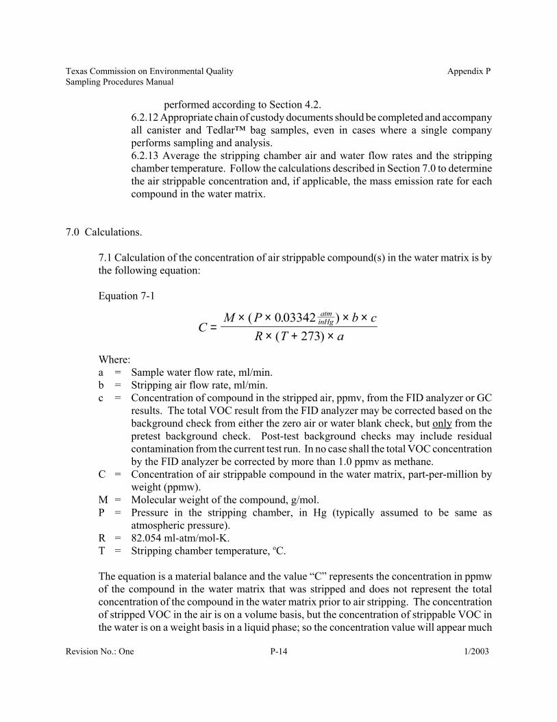
7.1 Calculation of the concentration of air strippable compound(s) in the water matrix is bythe following equation:
Equation 7-1
Where:a = Sample water flow rate, ml/min.b = Stripping air flow rate, ml/min.c = Concentration of compound in the stripped air, ppmv, from the FID analyzer or GC
results. The total VOC result from the FID analyzer may be corrected based on thebackground check from either the zero air or water blank check, but only from thepretest background check. Post-test background checks may include residualcontamination from the current test run. In no case shall the total VOC concentrationby the FID analyzer be corrected by more than 1.0 ppmv as methane.
C = Concentration of air strippable compound in the water matrix, part-per-million byweight (ppmw).
M = Molecular weight of the compound, g/mol.P = Pressure in the stripping chamber, in Hg (typically assumed to be same as
atmospheric pressure).R = 82.054 ml-atm/mol-K.T = Stripping chamber temperature, oC.
The equation is a material balance and the value “C” represents the concentration in ppmwof the compound in the water matrix that was stripped and does not represent the totalconcentration of the compound in the water matrix prior to air stripping. The concentrationof stripped VOC in the air is on a volume basis, but the concentration of strippable VOC inthe water is on a weight basis in a liquid phase; so the concentration value will appear much
Texas Commission on Environmental Quality Appendix PSampling Procedures Manual
Revision No.: One 1/2003P-15
E C Fhr
lbgallon ppm
= × × × ×60 8 337 1
1 000 000min .
, ,
cR T a
P bE ppmFlb
molatminHg
lbgallon hr
'( )
. ( . )' , ,
. min=× + ×
× × ××
×× ×
27316 04 0 03342
1 000 0008 337 60
higher for the air phase.
7.2 Molecular weight. For total VOC based on the portable FID analyzer procedure inSection 6.1, calculate total VOC concentration in the water and emission rate based on themolecular weight of methane, unless an alternative reference calibration standard isapproved by the TCEQ. For speciated VOC results based on procedures in Section 6.2,calculate individual compound concentrations and emission rates based on the respectivecompound molecular weights.
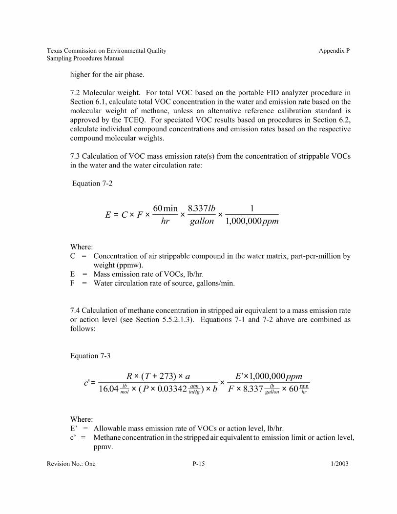
7.3 Calculation of VOC mass emission rate(s) from the concentration of strippable VOCsin the water and the water circulation rate:
Equation 7-2
Where:C = Concentration of air strippable compound in the water matrix, part-per-million by
weight (ppmw).E = Mass emission rate of VOCs, lb/hr.F = Water circulation rate of source, gallons/min.
7.4 Calculation of methane concentration in stripped air equivalent to a mass emission rateor action level (see Section 5.5.2.1.3). Equations 7-1 and 7-2 above are combined asfollows:
Equation 7-3
Where:E’ = Allowable mass emission rate of VOCs or action level, lb/hr.c’ = Methane concentration in the stripped air equivalent to emission limit or action level,
ppmv.
Texas Commission on Environmental Quality Appendix PSampling Procedures Manual
Revision No.: One 1/2003P-16
16.04 = Molecular weight of methane, lb/mol. If a different calibration gas is used for theportable FID analyzer, such as ethylene, use the appropriate molecular weight.
8.0 Use of Portable GC for Field Speciation Analysis. A portable GC, calibrated for a specific suiteof compounds, may be used in place of a FID analyzer, in which case the calculations remain thesame and the final result is the concentrations of speciated air strippable compounds in the watermatrix.
8.1 Setup. Same as Section 5.1, except calibration procedures for field GC analysis willfollow Section 4.2.
8.2 Blank/Background Check. Same as Section 5.5.8.2.1 Note: In some situations where very low detection for specific compounds isrequired, it may be preferable to check for background using the field GC.
8.3 Sample Measurement. Same as Section 6.1 with the following exceptions:8.3.1 The FID analyzer can be used during the stabilization period to monitor the airstripping apparatus effluent. Alternatively, the GC can be used to monitor during thestabilization period; however, such an approach may drastically increase the timeneeded.8.3.2 A test shall consist of three separate injection/analyses of the stripped gases.
9.0 References.9.1 Vernon, W. D. et. al., “A Device for Measuring Volatile Organic Carbon Emissionsfrom Cooling Towers Water,” Journal of Air Pollution Control Association, December,1981, pages 1280-1282.
9.2 United States Environmental Protection Agency Method 18 “Measurement of GaseousOrganic Compound Emissions by Gas Chromatography,” Code of Federal Regulations, Title40, Part 60, Appendix A, as amended through October 17, 2000 (65 FR 61744).
9.3 United States Environmental Protection Agency Method 21 “Determination of VolatileOrganic Compound Leaks,” Code of Federal Regulations, Title 40, Part 60, Appendix A, asamended through October 17, 2000 (65 FR 61744).
9.4 United States Environmental Protection Agency Compendium Method TO-14A“Determination of Volatile Organic Compounds (VOCs) in Ambient Air Using SpeciallyPrepared Canisters with Subsequent Analysis by Gas Chromatography,” Compendium of
Texas Commission on Environmental Quality Appendix PSampling Procedures Manual
Revision No.: One 1/2003P-17
Methods for Determination of Toxic Organic Compounds in Ambient Air, EPA DocumentNumber 625/R96/010B, January 1999.
Texas Commission on Environmental Quality Appendix PSampling Procedures Manual
Revision No.: One 1/2003P-18
Air Stripping Apparatus forStrippable VOCs from Water
To FID Analyzer/Sample Canister
Bubbler(250 ml flask)
Vent
WaterOverflow
WaterLevel
Stripping Chamber 36" x 3"Packed 26" Deep w/ BerylSaddles (6 - 8 mm size)
Air Rotameter
Water RotameterTemperature
Probe
MoistureKnock-out(250 ml flask)
Sample Water In
Stripping Air In
ColumnDrainValve
Securing Clamp
NeopreneStopper
1/4" Stainless Steelor Teflon Tubing
ExcessStripped Air
NeopreneStopper
Water Flow Path
Air Flow Path
Figure 1
Texas Commission on Environmental Quality Appendix PSampling Procedures Manual
Revision No.: One 1/2003P-19
Air Stripping ApparatusStripping Chamber End Cap Design
TemperatureProbe
Water Inlet Line(must be centered)
Stripped GasExit Line
Stripping Chamber Top
Top View Side View
Stripped GasExit Line
Water Inlet Line(must be centered)
Stripping Chamber Bottom
Top View Side View
3 - 4
inch
es
0.5 inch
0.5 inch 0.25 inch
Stripping Air Inlet Line(must be centered)
Water Drain Line
Water Drain Line
Stripping Air Inlet Line(must be centered)
Figure 2
Texas Commission on Environmental Quality Appendix PSampling Procedures Manual
Revision No.: One 1/2003P-20
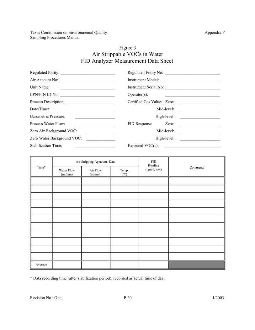
Figure 3Air Strippable VOCs in Water
FID Analyzer Measurement Data Sheet
Regulated Entity: __________________________ Regulated Entity No: __________________________
Air Account No: __________________________ Instrument Model: __________________________
Unit Name: __________________________ Instrument Serial No: __________________________
EPN/FIN ID No: __________________________ Operator(s): __________________________
Process Description: _______________________ Certified Gas Value: Zero: ___________________
Date/Time: __________________________ Mid-level: ___________________
Barometric Pressure: ___________________ High-level: ___________________
Process Water Flow: ___________________ FID Response Zero: ___________________
Zero Air Background VOC: ______________ Mid-level: ___________________
Zero Water Background VOC: ______________ High-level: ___________________
Stabilization Time: ___________________ Expected VOC(s): __________________________
Time*
Air Stripping Apparatus Data FIDReading
(ppmv, wet) CommentsWater Flow
(ml/min)Air Flow(ml/min)
Temp.(oC)
Average
* Data recording time (after stabilization period), recorded as actual time of day.
Texas Commission on Environmental Quality Appendix PSampling Procedures Manual
Revision No.: One 1/2003P-21
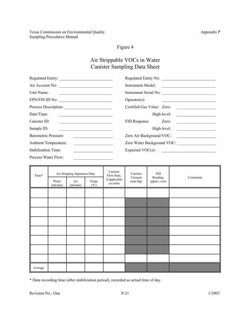
Figure 4
Air Strippable VOCs in WaterCanister Sampling Data Sheet
Regulated Entity: __________________________ Regulated Entity No: __________________________
Air Account No: __________________________ Instrument Model: __________________________
Unit Name: __________________________ Instrument Serial No: __________________________
EPN/FIN ID No: __________________________ Operator(s): __________________________
Process Description: _______________________ Certified Gas Value: Zero: ___________________
Date/Time: __________________________ High-level: ___________________
Canister ID: __________________________ FID Response Zero: ___________________
Sample ID: __________________________ High-level: ___________________
Barometric Pressure: ___________________ Zero Air Background VOC: ___________________
Ambient Temperature: ___________________ Zero Water Background VOC: ___________________
Stabilization Time: ___________________ Expected VOC(s): __________________________
Process Water Flow: ___________________
Time* Air Stripping Apparatus Data CanisterFlow Rate,
if applicable(cc/min)
CanisterVacuum(mm Hg)
FIDReading,
(ppmv, wet)Comments
Water(ml/min)
Air(ml/min)
Temp.(oC)
Average
* Data recording time (after stabilization period), recorded as actual time of day.


