
M A D E B Y E N T H U S I A S T S
A U X I L A R Y T A N K
I N S T A L L A T I O N I N S T R U C T I O N S
R A D E G A R A G E . C O M

R A D E G A R A G E . C O M I N S T A L L A T I O N I N S T R U C T I O N S 7 0 1
Thank you for buying Rade Garage Auxilary Tank HQ 701. Before you start enjoying the extra range of your bike, please read the following instructions. Please note, that to complete the installation you’ll need approximatelly 2–3 hours. The Kit is prepared so that only one pair of hands will be needed. Have fun and enjoy your “new” bike!
D E A R M O T O R C Y C L E E N T H U S I A S T S A N D R A D E G A R A G E F A N S

R A D E G A R A G E . C O M I N S T A L L A T I O N I N S T R U C T I O N S 7 0 11/1 6
1.At first have a look, what al l you get in your Rade Garage box.
TIP:Before you begin, just ride up
the OEM tank empty.
Pre-oiled foam air filter
Carbon cover
T-connection
Tank + fuel cap & outflow
Small airbox
Petcock
Fuel & vent tubes & 4 × hose clamps
Vent cap
Velcro strap
OEM tank connection
Filter cage & frame
Tank bracket
1
2
3
4
5
6
7
8
9
10
11
12
Pre-oiled foam air filter
Carbon cover
T-connection
Tank + fuel cap & outflow
Fuel & vent tubes & 4 × hose clampsSmall airbox
Petcock
Filter cage & frameTank bracket
Velcro strapOEM tank connection
Vent cap
1
2
3
4
5
6
7
8
9
10
1112
R A D E G A R A G E . C O M I N S T A L L A T I O N I N S T R U C T I O N S 7 0 12 /1 6
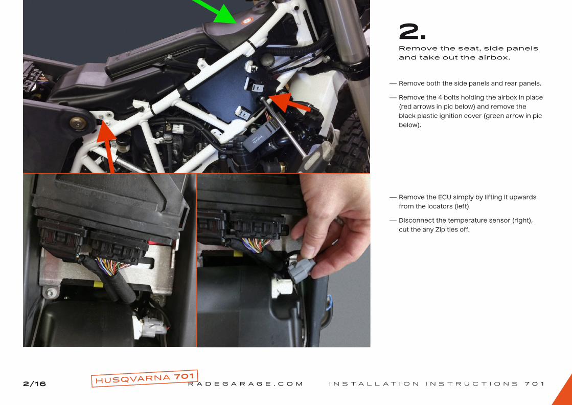
2.
- Remove both the side panels and rear panels.
- Remove the 4 bolts holding the airbox in place
(red arrows in pic below) and remove the
black plastic ignition cover (green arrow in pic
below).
- Remove the ECU simply by lifting it upwards
from the locators (left)
- Disconnect the temperature sensor (right),
cut the any Zip ties off.
Remove the seat , side panels and take out the airbox.
R A D E G A R A G E . C O M I N S T A L L A T I O N I N S T R U C T I O N S 7 0 13/1 6
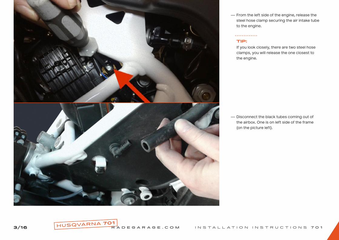
- From the left side of the engine, release the
steel hose clamp securing the air intake tube
to the engine.
- Disconnect the black tubes coming out of
the airbox. One is on left side of the frame
(on the picture left).
TIP:If you look closely, there are two steel hose
clamps, you will release the one closest to
the engine.
R A D E G A R A G E . C O M I N S T A L L A T I O N I N S T R U C T I O N S 7 0 14/1 6
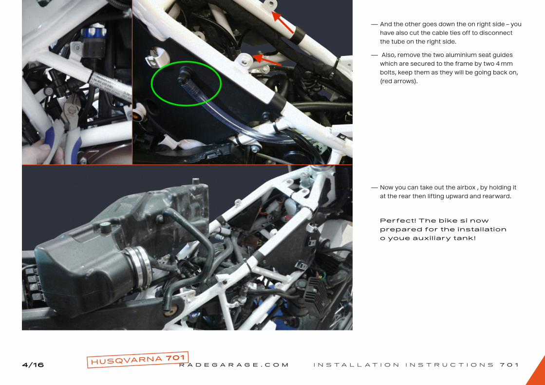
- And the other goes down the on right side – you
have also cut the cable ties off to disconnect
the tube on the right side.
- Also, remove the two aluminium seat guides
which are secured to the frame by two 4 mm
bolts, keep them as they will be going back on,
(red arrows).
- Now you can take out the airbox , by holding it
at the rear then lifting upward and rearward.
Perfect! The bike si now prepared for the installation o youe auxil iary tank!

R A D E G A R A G E . C O M I N S T A L L A T I O N I N S T R U C T I O N S 7 0 15/1 6
3.
- Remove the heat sensor from OEM airbox,
keep the screws (you will need them later)
and make sure you don’t loose the very small
rubber O-ring on the heat sensor.
- Remove the 50 mm hose clamp and take out
the rubber fitting/intake.
Remove the intake and heat sensor.
TIP:Open the OEM airbox from top, remove the
filter and put one hand in to better push out
the intake and use your second hand to pull
it out … you have to squeeze it a little to get it
out! Don’t worry – it is rubber and it has the
shape memory.

R A D E G A R A G E . C O M I N S T A L L A T I O N I N S T R U C T I O N S 7 0 16/1 6
4.
- Insert the rubber intake into the “small airbox”
and fasten the steel hose clamp steel hose
clamp.
- Use the OEM screws and fix the heat sensor
to the “small airbox” (make sure the O-ring is
on the heat sensor).
Complete the “small airbox” and fi lter.
- Here you can see all the filter parts: pre-oiled
foam filter, cage for the filter and the frame
with two bolts.
Pre-oiled foam air filter
The cage
The frame & M5 bolts
1
2
3
Pre-oiled foam air filter
The cage
The frame & M5 bolts
1
2
3
R A D E G A R A G E . C O M I N S T A L L A T I O N I N S T R U C T I O N S 7 0 17/1 6
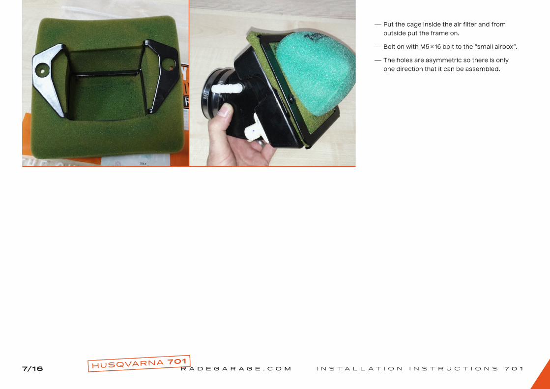
- Put the cage inside the air filter and from
outside put the frame on.
- Bolt on with M5 × 16 bolt to the “small airbox”.
- The holes are asymmetric so there is only
one direction that it can be assembled.

R A D E G A R A G E . C O M I N S T A L L A T I O N I N S T R U C T I O N S 7 0 18/1 6
5.
- See, what you get in the “tank package”.
Start mounting the small airbox into the bike.
- Now you have to cut the transparent vent
tube into 3 pieces (about 20 cm long) … but
measure before you cut!
- You must replace the two black OEM tubes
that go from the OEM airbox:
a) One tube has to start on left front side
(engine breather).
b) The second tube goes to the SAS assembly.
c) Connect both tubes with the white T-fitting
and then connect it to the small airbox
(right), for a better fit you may warm the tube
(you can use a hair dryer, left).

R A D E G A R A G E . C O M I N S T A L L A T I O N I N S T R U C T I O N S 7 0 19/1 6
- Before you insert the “small airbox” into the
bike, make sure you connect the vent tube and
electrical connector to the heat sensor!
- Next, install the rear tank bracket (see the pic
below).
- This kit does not require any front tank
bracket for the new tank to rest on; rather,
it simply sits on top of the horizontal frame
tube already in place, just make sure to
relocate any Zip ties/cable ties that may rub
on the tank.
TIP:When installing the rear tank bracket, make
sure the bolts are inserted from the inside of
the bike to the outside of the bike (i. e.: from
the air filter side to the outside, see red arrow
in the pic below, left). This ensures the nuts
are facing toward the outside of the bike.
R A D E G A R A G E . C O M I N S T A L L A T I O N I N S T R U C T I O N S 7 0 11 0/1 6
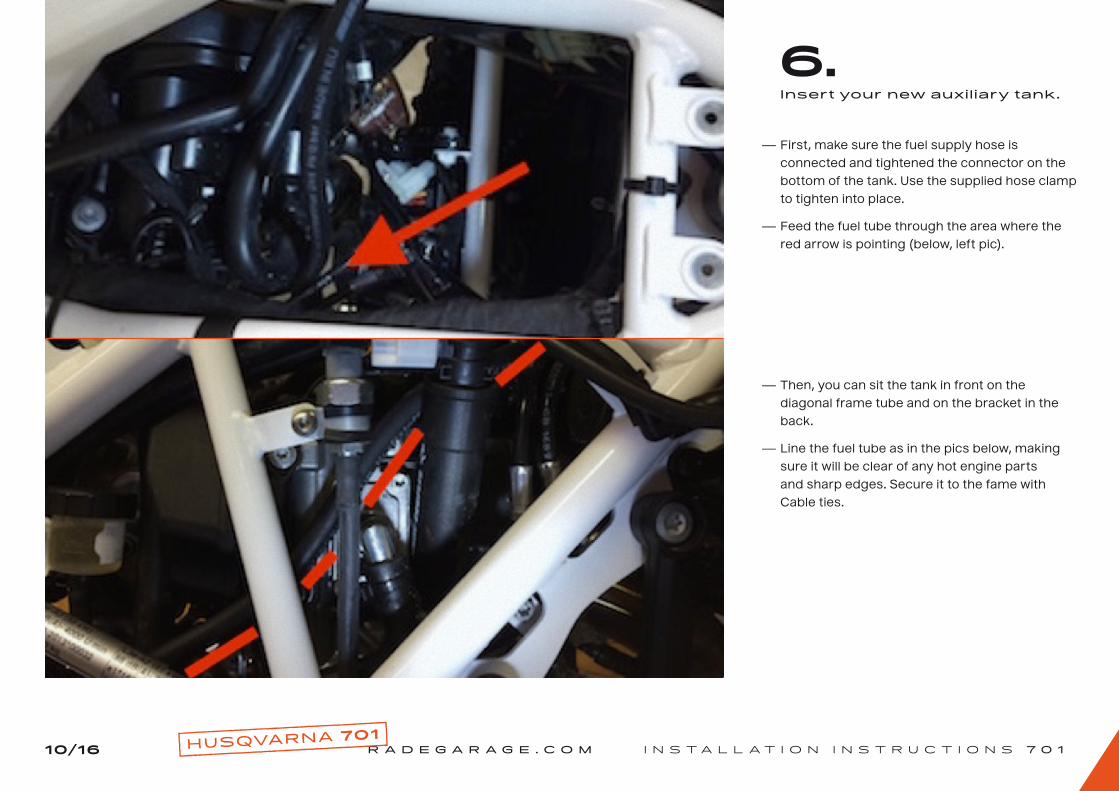
6.
- First, make sure the fuel supply hose is
connected and tightened the connector on the
bottom of the tank. Use the supplied hose clamp
to tighten into place.
- Feed the fuel tube through the area where the
red arrow is pointing (below, left pic).
- Then, you can sit the tank in front on the
diagonal frame tube and on the bracket in the
back.
- Line the fuel tube as in the pics below, making
sure it will be clear of any hot engine parts
and sharp edges. Secure it to the fame with
Cable ties.
Insert your new auxil iary tank.

R A D E G A R A G E . C O M I N S T A L L A T I O N I N S T R U C T I O N S 7 0 111/1 6
- Now you have the tank in the frame like this
(see pic below).
- Re-install the electric cooler and the two
aluminium seat guides.
- Replace the plastic ignition cover grommets
(in the frame tabs) with the supplied M5
speed nuts and mount the carbon ignition
cover piece with the supplied M5 bolts.
R A D E G A R A G E . C O M I N S T A L L A T I O N I N S T R U C T I O N S 7 0 11 2 /1 6
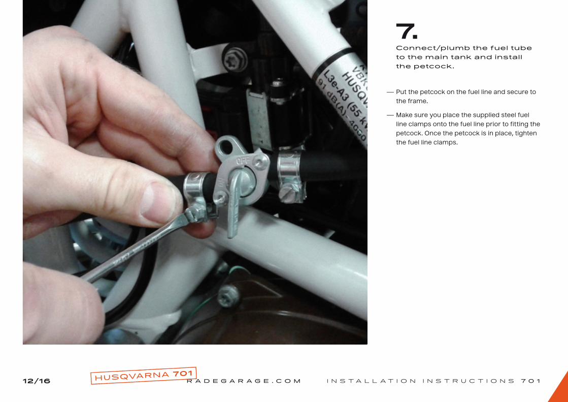
7.
- Put the petcock on the fuel line and secure to
the frame.
- Make sure you place the supplied steel fuel
line clamps onto the fuel line prior to fitting the
petcock. Once the petcock is in place, tighten
the fuel line clamps.
Connect/plumb the fuel tube to the main tank and install the petcock.

R A D E G A R A G E . C O M I N S T A L L A T I O N I N S T R U C T I O N S 7 0 11 3/1 6
8.Co n n e c t t h e a u x i l i a r y t a n k to t h e m a i n t a n k .
- First, remove the rear (fuel tank mudguard),
(see green arrow in below pic). Then, remove
the 4 screws holding the fuel pump assembly to
the OEM fuel tank (see red cirdle in below pic).
TIP:As mentioned, we recommend emptying the
main tank as much as you can before this
step – just ride up to the reserve.
TIP:The pic below shows the black plastic cover
removed from the fuel pump.
- Carefully pull down on the fuel pump assembly
until you can see the two lock tabs either
side of the pump housing, (see green circle
in below pic). Using a small flat screwdriver,
carefully depress both tabs to release the
black plastic pump cover. With both tabs
depressed, remove the black plastic fuel pump
cover. Note the actual fuel pump remains
connected and in place in the fuel tank.
CAUTION:Any fuel remaining in the tank will spill during
this procedure, place a suitable container
under the tank to catch spillage.

R A D E G A R A G E . C O M I N S T A L L A T I O N I N S T R U C T I O N S 7 0 114/1 6
- Summary of this step: 2 × 4 mm holes must be
drilled into the black plastic fuel pump cover.
One directly behind where the banjo bolt goes
on the aluminum spacer.
- If the banjo bolt is currently installed in the
aluminium spacer, remove it. Place the
aluminium spacer over the fuel pump cover with
the O-ring groove facing up.
- Insert a 4 mm drill bit through the threaded hole
where the banjo bolt will be installed and drill
very lightly into the black plastic cover, with just
enough pressure to mark the plastic cover. Be
careful not damage the threads. Remove the
banjo bolt and continue to drill the marked hole.
(See green arrow in the pic below, left).
- Clean any plastic shavings from the black plastic
fuel pump cover and aluminium spacer.
- Insert the supplied aluminium spacer over the
black plastic cover, with the O-ring groove and
O-ring facing up towards the fuel tank.
- Correct installation has the rubber O-ring on top
and the outflow on the right side of the bike (see
below pic).
R A D E G A R A G E . C O M I N S T A L L A T I O N I N S T R U C T I O N S 7 0 11 5/1 6
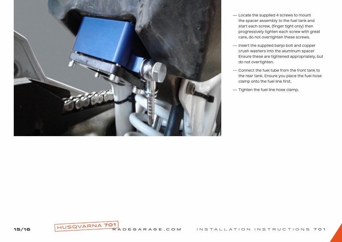
- Locate the supplied 4 screws to mount
the spacer assembly to the fuel tank and
start each screw, (finger tight only) then
progressively tighten each screw with great
care, do not overtighten these screws.
- Insert the supplied banjo bolt and copper
crush washers into the aluminum spacer
Ensure these are tightened appropriately, but
do not overtighten.
- Connect the fuel tube from the front tank to
the rear tank. Ensure you place the fuel hose
clamp onto the fuel line first.
- Tighten the fuel line hose clamp.

R A D E G A R A G E . C O M I N S T A L L A T I O N I N S T R U C T I O N S 7 0 11 6/1 6
I hope these instructions helped and you enjoy the extended range of your bike and the freedom which it brings. If you have any questions about installation, feel free to send us an email at [email protected]
C O N G R A T U L A T I O N S O N A S U C C E S S F U L I N S T A L L A T I O N !
RIDE HARD, RIDE SAFE!YOUR RADE GARAGE TEAM


