plug in relays - bch india-switchgear …portal.bchindia.com/forms/catalog/plug in relays.pdf ·...
TRANSCRIPT
PLUG IN RELAYS
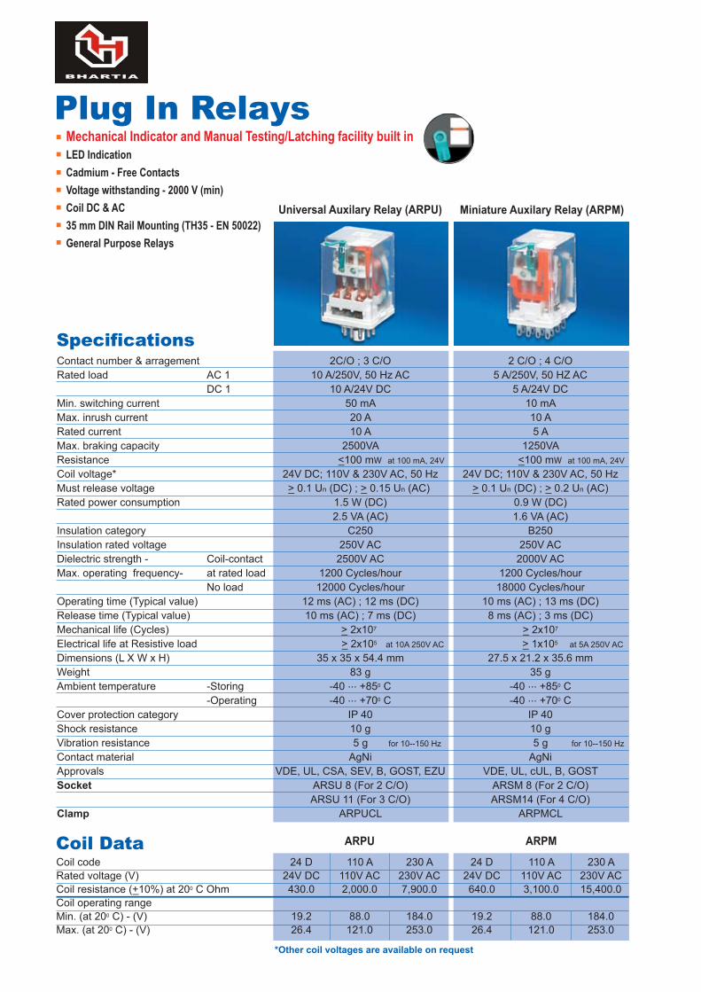
Contact number & arragement 2C/O ; 3 C/O 2 C/O ; 4 C/ORated load AC 1 10 A/250V, 50 Hz AC 5 A/250V, 50 HZ AC DC 1 10 A/24V DC 5 A/24V DCMin. switching current 50 mA 10 mAMax. inrush current 20 A 10 ARated current 10 A 5 A Max. braking capacity 2500VA 1250VAResistance <_100 mW at 100 mA, 24V <_100 mW at 100 mA, 24V
Coil voltage* 24V DC; 110V & 230V AC, 50 Hz 24V DC; 110V & 230V AC, 50 HzMust release voltage >_ 0.1 Un (DC) ; >_ 0.15 Un (AC) >_ 0.1 Un (DC) ; >_ 0.2 Un (AC)Rated power consumption 1.5 W (DC) 0.9 W (DC) 2.5 VA (AC) 1.6 VA (AC)Insulation category C250 B250Insulation rated voltage 250V AC 250V ACDielectric strength - Coil-contact 2500V AC 2000V ACMax. operating frequency- at rated load 1200 Cycles/hour 1200 Cycles/hour No load 12000 Cycles/hour 18000 Cycles/hourOperating time (Typical value) 12 ms (AC) ; 12 ms (DC) 10 ms (AC) ; 13 ms (DC)Release time (Typical value) 10 ms (AC) ; 7 ms (DC) 8 ms (AC) ; 3 ms (DC)Mechanical life (Cycles) >_ 2x10⁷ >_ 2x10⁷
Electrical life at Resistive load >_ 2x10⁵ at 10A 250V AC >_ 1x10⁵
at 5A 250V AC
Dimensions (L X W x H) 35 x 35 x 54.4 mm 27.5 x 21.2 x 35.6 mmWeight 83 g 35 gAmbient temperature -Storing -40 ... +850 C -40 ... +850 C -Operating -40 ... +700 C -40 ... +700 CCover protection category IP 40 IP 40Shock resistance 10 g 10 gVibration resistance 5 g for 10--150 Hz 5 g for 10--150 Hz
Contact material AgNi AgNi Approvals VDE, UL, CSA, SEV, B, GOST, EZU VDE, UL, cUL, B, GOSTSocket ARSU 8 (For 2 C/O) ARSM 8 (For 2 C/O) ARSU 11 (For 3 C/O) ARSM14 (For 4 C/O)Clamp ARPUCL ARPMCL
Plug In RelaysMechanical Indicator and Manual Testing/Latching facility built inLED IndicationCadmium - Free ContactsVoltage withstanding - 2000 V (min)Coil DC & AC35 mm DIN Rail Mounting (TH35 - EN 50022)General Purpose Relays
Specifications
Universal Auxilary Relay (ARPU) Miniature Auxilary Relay (ARPM)
ARPU ARPM
Coil code 24 D 110 A 230 A 24 D 110 A 230 ARated voltage (V) 24V DC 110V AC 230V AC 24V DC 110V AC 230V ACCoil resistance (+_10%) at 200 C Ohm 430.0 2,000.0 7,900.0 640.0 3,100.0 15,400.0Coil operating rangeMin. (at 200 C) - (V) 19.2 88.0 184.0 19.2 88.0 184.0Max. (at 200 C) - (V) 26.4 121.0 253.0 26.4 121.0 253.0
Coil Data
*Other coil voltages are available on request
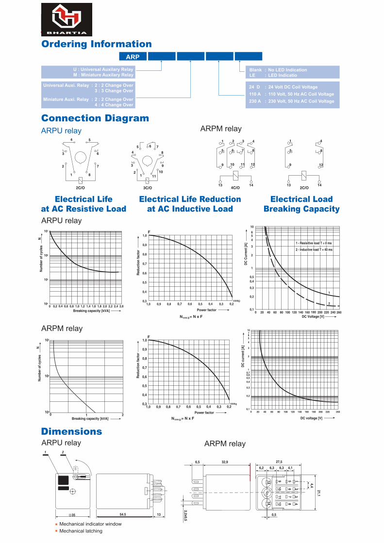
ARP
U : Universal Auxilary RelayM : Miniature Auxilary Relay
Universal Auxi. Relay : 2 : 2 Change Over 3 : 3 Change Over
Miniature Auxi. Relay : 2 : 2 Change Over 4 : 4 Change Over
Connection DiagramARPU relay
ARPU relay
ARPM relay
ARPM relay
Ordering Information
24 D : 24 Volt DC Coil Voltage110 A : 110 Volt, 50 Hz AC Coil Voltage230 A : 230 Volt, 50 Hz AC Coil Voltage
Blank : No LED IndicationLE : LED Indicatio
Electrical Lifeat AC Resistive Load
Electrical Life Reductionat AC Inductive Load
Electrical LoadBreaking Capacity
DimensionsARPU relay
Mechanical indicator windowMechanical latching
4 5
63
2
1 8
7
2C/O
3 9
8765
4
21 11
10
3C/O
1 2 3 4
5 6 7 8
9 10 11 12
144C/O
13
1 4
5 8
9
2C/O1413
12
107
106
105
104
0 0,2 0,4 0,6 0,8 1,0 1,2Breaking capacity [kVA]
Num
ber o
f cyc
les
N
1,4 1,6 1,8 2,0 2,2 2,4 2,6
= N x FNcos
0,2
0,4
0,30,4 0,3
0,6
0,6
0,5
0,5
Power factor
0,8
0,7
0,7
0,9
1,0 0,9 0,8
1,0F
cos
Redu
ctio
n fa
ctor
0
10
654
3
2
1
0,50,4
0,3
0,2
0,120 40 60 80 100 120 140
DC Voltage [V]160 180 200 220 240 260
2
1
DC C
urre
nt [A
] 1 - Resisitive load T = 0 ms
2 - Inductive load T = 40 ms
0 1 2Breaking capacity [kVA]
107
106
105
Num
ber o
f cyc
les
N
107654
3
2
10,70,60,50,4
0,3
0,2
0,10 20 40 60 80 100 120 140 160 180 200 220 250
DC voltage [V]
DC c
urre
nt [A
]
= N x FNcos
0,2
0,4
0,30,4 0,3
0,6
0,6
0,5
0,5
Power factor
0,8
0,7
0,7
0,9
1,0 0,9 0,8
1,0F
cos
Redu
ctio
n fa
ctor
1354.5
1 2
35
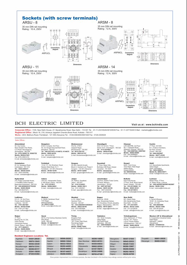
ARSU - 8
ARSU - 11
ARSM - 8
ARSM - 14
Sockets (with screw terminals)
35 mm DIN rail mountingRating : 12 A, 300V
35 mm DIN rail mountingRating : 12 A, 300V
35 mm DIN rail mountingRating : 10 A, 250V
35 mm DIN rail mountingRating : 10 A, 250V
ARPUCL
8
9
Connections diagram
10 11 1
1 234
5678
91011
2 3
7 6 5 4
5
3,5
7,8
68,2
524
3,2
6,4
8
32
34
9 10 11 1 2 3
31 11 14A2 A1
24 21 22 12
7 6 5 4
3038
Dimensions
35
24,2
18,5
1,1
5 43
218
7
6
6
7 8 1 2
5 4 3
Connections diagram
18,5
153,5
35
1,1
24,2
3,5
5
6
34
B
7 8 1
30
68,2 52 7,8
1,5
4 x
3,2
6,4
38
2
31 11 A
32 12 14
5 4 3
Dimensions
8 7 6 5
1234
A214 13
12 11 10 9
A1
Connections diagram
42,5
3
3575
27 24
Dimensions
3,2
27 22,5
8
4
14
12
13
9
5
1
A1A2
Connections diagram
3
35
2427
42,5
75
27 22,5
Dimensions
ARPUCL
ARPUCL
ARPMCL
ARPMCL
AU
T/PR
ELA
Y/5
000/
OC
T. '0
4R
P./5
000/
Jan
'08