
CSIS 254 CSIS 254 Oracle Database DesignOracle Database Design
Day 3Day 3

Today’s AgendaToday’s Agenda
• Questions on homeworkQuestions on homework
• Review key concepts from last weekReview key concepts from last week
• Continue with Analysis stage of SDLCContinue with Analysis stage of SDLC– Entity Life History DiagramsEntity Life History Diagrams– Data Flow DiagramsData Flow Diagrams– Relational Databases Relational Databases

Seven System Development StagesSeven System Development Stages(Review)(Review)
The Software Development Life CycleThe Software Development Life Cycle– Strategy / ScopeStrategy / Scope– AnalysisAnalysis– DesignDesign– ProgrammingProgramming– TestingTesting– Go LiveGo Live– Production & MaintenanceProduction & Maintenance

The Entity Relationship ModelThe Entity Relationship Model (ERM)(ERM)
EntitiesEntities
• EntitiesEntities are people, places, things, or events of interest are people, places, things, or events of interest to our system that can be divided into distinct classesto our system that can be divided into distinct classes
– An entity may describe physical things, or it may An entity may describe physical things, or it may be conceptualbe conceptual
• Entity typesEntity types (or (or sets) sets) are collections of entities having are collections of entities having similar propertiessimilar properties
• Each Each occurrenceoccurrence of an entity type can also be called of an entity type can also be called an an instanceinstance or an or an objectobject

The Entity Relationship Model (ERM)The Entity Relationship Model (ERM)
AttributesAttributes
• Attributes Attributes are relevant properties or characteristics are relevant properties or characteristics that describe the entity instances in an entity setthat describe the entity instances in an entity set
• An attribute may be An attribute may be simplesimple (atomic) or (atomic) or compositecomposite
• An attribute may also be An attribute may also be single-valuedsingle-valued or or multi-multi-valuedvalued
• The values of an attribute in an entity instance The values of an attribute in an entity instance may be restricted:may be restricted:– mandatory, uniqueness, formatting, restricted domain...mandatory, uniqueness, formatting, restricted domain...

The Entity Relationship Model (ERM)The Entity Relationship Model (ERM)
KeysKeys
• An attribute (or combination of attributes) that uniquely An attribute (or combination of attributes) that uniquely identify an entity is called a identify an entity is called a keykey attribute attribute
• Key attributes are limited to the Key attributes are limited to the minimumminimum set of set of attributes that can uniquely identify an entityattributes that can uniquely identify an entity
• When an entity has more than one set of key attributes, When an entity has more than one set of key attributes, they are called they are called candidate keyscandidate keys
• When a key does not contain any descriptive data about When a key does not contain any descriptive data about the entity,it is called a the entity,it is called a surrogatesurrogate or or naturalnatural key, or an key, or an identifieridentifier

The Entity Relationship Model (ERM)The Entity Relationship Model (ERM)
Derived AttributesDerived Attributes• A A derived attributederived attribute is one that can be determined based is one that can be determined based
upon the values of other attributes in the entity object upon the values of other attributes in the entity object or related entity objectsor related entity objects
• These might it be beneficial for us to include derived These might it be beneficial for us to include derived attributes in our physical database designattributes in our physical database design
– PerformancePerformance
– RedundancyRedundancy
– Security Security
– Consistency (??)Consistency (??)
– Snapshots in time (as of)Snapshots in time (as of)
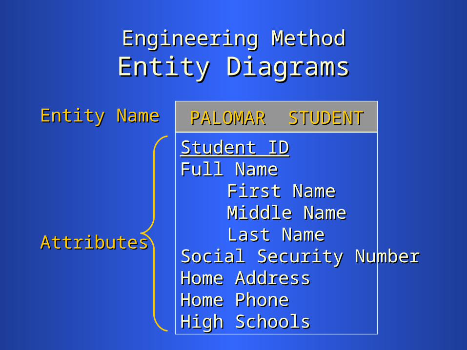
Engineering MethodEngineering Method
Entity DiagramsEntity Diagrams
Entity NameEntity Name
AttributesAttributes
PALOMAR STUDENTPALOMAR STUDENT
Student IDStudent IDFull NameFull Name
First NameFirst NameMiddle NameMiddle NameLast NameLast Name
Social Security NumberSocial Security NumberHome AddressHome AddressHome PhoneHome PhoneHigh SchoolsHigh Schools

Engineering MethodEngineering Method
Entity DiagramsEntity Diagrams
A familiarA familiar Key Key
exampleexample AttributeAttribute
PUBLISHERPUBLISHER
Publisher IdPublisher IdPublisher NamePublisher NameStreet AddressStreet AddressCityCityStateState

The Entity Relationship Model (ERM)The Entity Relationship Model (ERM)
Weak Entity TypesWeak Entity Types
• Entity types that do not have key attributes of their Entity types that do not have key attributes of their own are called own are called weakweak entity types entity types
• Weak entities are always related to specific Weak entities are always related to specific entities from another entity type -- the entities from another entity type -- the ownerowner
• A weak entity must have a A weak entity must have a partial key partial key or anor an identifieridentifier, which is a set of attributes that can be , which is a set of attributes that can be used to uniquely identify each instance from other used to uniquely identify each instance from other instances instances belonging to the same ownerbelonging to the same owner

The Entity Relationship Model (ERM)The Entity Relationship Model (ERM)
Subtypes and SupertypesSubtypes and Supertypes
• When different entity types share the same attributes, When different entity types share the same attributes, we can break out the common attributes into we can break out the common attributes into SupertypesSupertypes, leaving the attributes that distinguish , leaving the attributes that distinguish entities into entities into SubtypesSubtypes
– There must be at least one attribute that There must be at least one attribute that distinguishes subtypes common to a supertypedistinguishes subtypes common to a supertype
– An entity instance must belong to one and only An entity instance must belong to one and only one subtypeone subtype

The Entity Relationship Model (ERM)The Entity Relationship Model (ERM)
RelationshipsRelationships
• A A relationshiprelationship is an association between two or more is an association between two or more entitiesentities
• Each relationship has an inverse relationshipEach relationship has an inverse relationship
• ParticipationParticipation or or optionalityoptionality refers to whether each refers to whether each entity instance must occur in the relationship (i.e., is it entity instance must occur in the relationship (i.e., is it a mandatory relationship)a mandatory relationship)
• The The degreedegree of a relationship is the number of of a relationship is the number of participating entity participating entity typestypes

CardinalityCardinality• CardinalityCardinality is the is the maximummaximum number of occurrences of number of occurrences of
each entity type that can occur in a relationship each entity type that can occur in a relationship
• In binary relationships:In binary relationships:– A A 1-to-1 1-to-1 relationship occurs when an entity of one type can relationship occurs when an entity of one type can
occur in (at most) one relationship with an entity of the other occur in (at most) one relationship with an entity of the other typetype
– A A 1-to-many1-to-many relationship occurs when an entity of one type relationship occurs when an entity of one type can occur in (at most) one relationship with the other type, can occur in (at most) one relationship with the other type, but entities or the second type can be related to any number of but entities or the second type can be related to any number of entities of the first type.entities of the first type.
– A A many-to-manymany-to-many relationship occurs when no restrictions relationship occurs when no restrictions exist on the number of entities that can participate in a exist on the number of entities that can participate in a relationshiprelationship

RelationshipsRelationships
ER DiagramsER Diagrams
In ERDs, entities that are related are connected by In ERDs, entities that are related are connected by lines. (A lines. (A 1-to-11-to-1 relationship is shown below.) relationship is shown below.)
SOCIALSOCIALSECURITYSECURITYNUMBERNUMBER
PALOMARPALOMARSTUDENT IDSTUDENT ID

RelationshipsRelationships
ER DiagramsER Diagrams
Crow’s feet are used at the “many” end in Crow’s feet are used at the “many” end in 1-to-many1-to-many
relationshipsrelationships..
COUNTRYCOUNTRY RULERRULER
has had ashas had asHead of StateHead of State

RelationshipsRelationships
ER DiagramsER Diagrams
Both sides of the line will have crow’s feet in a many-Both sides of the line will have crow’s feet in a many-to-many relationship.to-many relationship.
CARCARMODELMODEL
COLORCOLORGROUPGROUP
is availableis availableusingusing

RelationshipsRelationships
ER DiagramsER Diagrams
A small circle is placed at the end of an A small circle is placed at the end of an optionaloptional participation, and a small perpendicular line placed at participation, and a small perpendicular line placed at the end of a the end of a mandatorymandatory participation. participation.
WOMANWOMAN CHILDRENCHILDREN
is biologicalis biologicalmother ofmother of

RelationshipsRelationships
ER DiagramsER DiagramsSubtype entities reference their supertypes using Subtype entities reference their supertypes using arrows, rather than lines.arrows, rather than lines.
CARCAR TRUCKTRUCK BIKEBIKE
LICENSEDLICENSEDVEHICLEVEHICLE

RelationshipsRelationships
ER DiagramsER Diagrams
AllAll entity occurrences must fall into one of the subtypes entity occurrences must fall into one of the subtypes
CARCAR TRUCKTRUCK BIKEBIKE
LICENSEDLICENSEDVEHICLEVEHICLE
OTHEROTHER
We add an “other” We add an “other” category to include category to include
RV’s, planes, RV’s, planes, motorcycles, etc.motorcycles, etc.
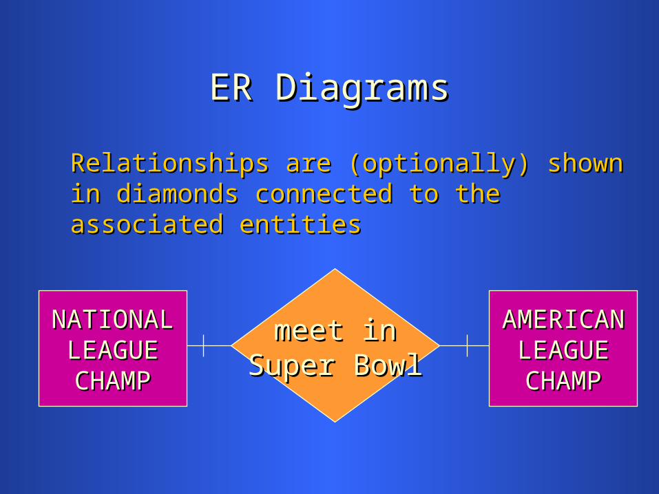
ER DiagramsER Diagrams
Relationships are (optionally) shown in diamonds Relationships are (optionally) shown in diamonds connected to the associated entitiesconnected to the associated entities
meet inmeet inSuper BowlSuper Bowl
NATIONALNATIONALLEAGUELEAGUECHAMPCHAMP
AMERICANAMERICANLEAGUELEAGUECHAMPCHAMP

Reflexive (Recursive) RelationshipsReflexive (Recursive) Relationships
• Occur when an entity has a relationship with Occur when an entity has a relationship with another entity in the same entity setanother entity in the same entity set
• We might need to add business rules prohibiting We might need to add business rules prohibiting certain recursive conditionscertain recursive conditions
• If participation is mandatory, then the relationship If participation is mandatory, then the relationship is is circularcircular
• If the relationship is If the relationship is hierarchicalhierarchical, then , then participation is optionalparticipation is optional

ER DiagramsER Diagrams
Reflexive relationships are drawn with a single Reflexive relationships are drawn with a single entity boxentity box
PERSONPERSON
is married tois married to
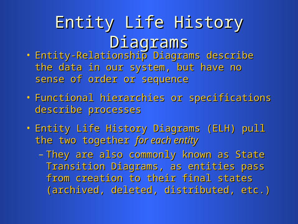
Entity Life History DiagramsEntity Life History Diagrams• Entity-Relationship Diagrams describe the data in Entity-Relationship Diagrams describe the data in
our system, but have no sense of order or sequenceour system, but have no sense of order or sequence
• Functional hierarchies or specifications describe Functional hierarchies or specifications describe processesprocesses
• Entity Life History Diagrams (ELH) pull the two Entity Life History Diagrams (ELH) pull the two together together for each entityfor each entity– They are also commonly known as State They are also commonly known as State
Transition Diagrams, as entities pass from Transition Diagrams, as entities pass from creation to their final states (archived, deleted, creation to their final states (archived, deleted, distributed, etc.) distributed, etc.)

Generic Entity Life History DiagramGeneric Entity Life History Diagram
EntityEntity
CreationCreation TransactionsTransactions Deletion orDeletion orArchiveArchive
Event 1Event 1 Event 3Event 3
Event AEvent A Event BEvent B
Event 2Event 2
oo oo
**

Entity Life History NotesEntity Life History Notes• The single entity being examined appears at the The single entity being examined appears at the
top of the diagramtop of the diagram
• The rest of the diagram is comprised of The rest of the diagram is comprised of events, events, which create, modify, or delete instances of the which create, modify, or delete instances of the entityentity
• A little ‘o’ in the upper-right corner of an event A little ‘o’ in the upper-right corner of an event means “option” or selectionmeans “option” or selection
• An asterisk ‘*’ in the upper-right corner means An asterisk ‘*’ in the upper-right corner means “iteration” or repetition“iteration” or repetition
• Basic flow of diagram is left-to-rightBasic flow of diagram is left-to-right

Entity Life History ExampleEntity Life History Example
Payroll CheckPayroll Check
Job CardsJob CardsTransferredTransferred
ProcessingProcessing ArchiveArchive
HoursHoursSummarizedSummarized
CheckCheckPrintedPrinted
ApprovedApproved RejectedRejected
ReviewsReviewsMadeMade
oo oo
**
2 years2 yearspasspass
CalculationsCalculationsPerformedPerformed

Data Flow DiagramsData Flow Diagrams
• Are used to uncover as many data elements as Are used to uncover as many data elements as possible in our data dictionarypossible in our data dictionary
• Document the system from the data’s viewpoint Document the system from the data’s viewpoint (i.e., are data-centric)(i.e., are data-centric)
• Contain several entities on each diagram (unlike Contain several entities on each diagram (unlike Entity Life History Diagrams)Entity Life History Diagrams)
• Differentiate manual from automated processesDifferentiate manual from automated processes
• Show both external and internal processesShow both external and internal processes

Data Flow Diagram ExampleData Flow Diagram Example
Purchase Requisition FulfillmentPurchase Requisition Fulfillment
SUPPLIERSUPPLIERissue P.O.issue P.O.
D1D1 Inventory InventoryEMPLOYEEEMPLOYEE
issue req.issue req.
BUYERBUYER
receive itemreceive item
D2D2 Accts Payable Accts Payableplace req.place req.
P1P1
review & review & approveapprove
confirmconfirm
P2P2
send tosend tocreate ordercreate order
ship itemship item
P3P3
match to invoicematch to invoice
updateupdatestockstock

Data Flow Diagram NotesData Flow Diagram Notes• Rectangles represent entitiesRectangles represent entities
• Open-ended rectangles represent databases or data Open-ended rectangles represent databases or data stores, and are labeled by a small box on their leftstores, and are labeled by a small box on their left
• Rounded rectangles represent processes, with the Rounded rectangles represent processes, with the top part of the rectangle having a process numbertop part of the rectangle having a process number
• Arrows represent data flows (either electronic or Arrows represent data flows (either electronic or physical)physical)
• Flow is generally from left-to-rightFlow is generally from left-to-right– Entities may appear more than once in the diagram to Entities may appear more than once in the diagram to
preserve the flow and directional naturepreserve the flow and directional nature

Data Flow Diagram RulesData Flow Diagram Rules
• All processes must have at least one flow of data All processes must have at least one flow of data coming in and one going outcoming in and one going out
• All processes on the diagram should modify the All processes on the diagram should modify the incoming data and create new forms of outgoing incoming data and create new forms of outgoing datadata
• Each data store and each external entity must be Each data store and each external entity must be involved with at least one data flowinvolved with at least one data flow

Relational DatabasesRelational Databases(Review)(Review)
• In relational databases, In relational databases, allall data is stored in tables, data is stored in tables, which correspond roughly to entitieswhich correspond roughly to entities
• Each table is two-dimensional, consisting of rows Each table is two-dimensional, consisting of rows and columnsand columns
• Each row in a table, called a Each row in a table, called a t-uplet-uple, corresponds to , corresponds to an occurrence of the entityan occurrence of the entity
• Columns in each table contain similar data across Columns in each table contain similar data across all rows in the tableall rows in the table

Relational Database ExampleRelational Database Example
The following table is an example of a relational table The following table is an example of a relational table describing classes that students have taken at a mythical describing classes that students have taken at a mythical college used in the rest of this lessoncollege used in the rest of this lesson
Student Student Course Student Student Course
Id Name Id Course Name Grade Term Teacher Id Name Id Course Name Grade Term Teacher
0194327 Joe Adams CSIS-840 VB Concepts C Spr-02 Wilkins0194327 Joe Adams CSIS-840 VB Concepts C Spr-02 Wilkins
0194327 Joe Adams CSIS-824 Intro to C++ B Fal-02 Smythe0194327 Joe Adams CSIS-824 Intro to C++ B Fal-02 Smythe
1850243 Joe Adams CSIS-740 Oracle Admin A Spr-03 Wallace1850243 Joe Adams CSIS-740 Oracle Admin A Spr-03 Wallace
1850243 Jane Smith CSIS-941 Systems Des. B Fal-02 Evans1850243 Jane Smith CSIS-941 Systems Des. B Fal-02 Evans
1850243 Jane Smith CSIS-840 VB Concepts B Spr-02 Wolkins1850243 Jane Smith CSIS-840 VB Concepts B Spr-02 Wolkins
8502432 Ida Know CSIS-184 Networks A Sum-03 Farmer8502432 Ida Know CSIS-184 Networks A Sum-03 Farmer
7402943 Eunice Eye CSIS-824 PowerPoint W Spr-02 Simpson7402943 Eunice Eye CSIS-824 PowerPoint W Spr-02 Simpson

Relational Database ExampleRelational Database Example
• Each row (or t-uple) in the table describes a Class Each row (or t-uple) in the table describes a Class taken by a Student in a term at our collegetaken by a Student in a term at our college
• The data in each column is consistent throughout the The data in each column is consistent throughout the tabletable
• However, there are three inconsistencies in the table However, there are three inconsistencies in the table itself. Can you find them?itself. Can you find them?

Primary Keys Primary Keys (Review)(Review)
• Each row in a table has a Each row in a table has a primary keyprimary key, which is the , which is the column or set of columns identified to our DBMS column or set of columns identified to our DBMS that uniquely identifies it from every other row in that uniquely identifies it from every other row in the tablethe table
• No attribute value in a primary key can be NULLNo attribute value in a primary key can be NULL
• A table can have only one primary keyA table can have only one primary key
• If a primary key is not specified, Oracle supplies oneIf a primary key is not specified, Oracle supplies one
• What would be the primary key for our sample What would be the primary key for our sample database?database?

Foreign KeysForeign Keys(Review)(Review)
• An attribute (or group of attributes) in a table can An attribute (or group of attributes) in a table can also be a also be a foreign keyforeign key, meaning that it references , meaning that it references the primary key (or at least unique attribute) to the primary key (or at least unique attribute) to another tableanother table
• An example would be a An example would be a Customer IdCustomer Id attribute on attribute on an invoice header, which would reference the an invoice header, which would reference the customer account information for that invoicecustomer account information for that invoice


