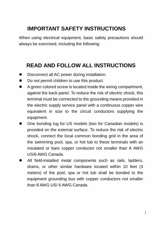
Electronic Chlorine Generator
Installation & Operation Manual
Millstream Distribution LLC
1-800-253-4775
www.millstreamdstr.com
1
IMPORTANT SAFETY INSTRUCTIONS
When using electrical equipment, basic safety precautions should
always be exercised, including the following:
READ AND FOLLOW ALL INSTRUCTIONS
Disconnect all AC power during installation.
Do not permit children to use this product.
A green colored screw is located inside the wiring compartment,
against the back panel. To reduce the risk of electric shock, this
terminal must be connected to the grounding means provided in
the electric supply service panel with a continuous copper wire
equivalent in size to the circuit conductors supplying the
equipment.
One bonding lug for US models (two for Canadian models) is
provided on the external surface. To reduce the risk of electric
shock, connect the local common bonding grid in the area of
the swimming pool, spa, or hot tub to these terminals with an
insulated or bare copper conductor not smaller than 8 AWG
US/6 AWG Canada.
All field-installed metal components such as rails, ladders,
drains, or other similar hardware located within 10 feet (3
meters) of the pool, spa or hot tub shall be bonded to the
equipment grounding bus with copper conductors not smaller
than 8 AWG US/ 6 AWG Canada.
2
SAVE THESE INSTRUCTIONS
Table of Contents
OPERATION
General..................................................................................4
Water chemistry....................................................................4
Controls...............................................................................11
Maintenance........................................................................14
INSTALLATION
Mounting.............................................................................15
Plumbing.............................................................................15
Wiring.................................................................................19
TROUBLESHOOTING
Troubleshooting.................................................................22
WARRANTY
Warranty...........................................................................26
3
OPERATION
The HydroSalt™ is an automatic chlorine generation system for pool & spa sanitation.
The operation requires a low concentration of salt (sodium chloride) in the pool water at
levels low enough that it normally cannot be tasted. HydroSalt™ automatically sanitizes
your pool by converting the salt into free chlorine, which kills bacteria and algae in the
pool through a process called electrolysis.
HydroSalt™ is designed to handle the purification needs of the average residential
swimming pool up to 40,000 gallons (150,000 liters). The actual amount of chlorination
required to properly sanitize a pool varies depending upon bather load, rainfall, air
temperature, water temperature, pool’s exposure to sunlight, pool’s surface, and
cleanliness.
Note: It is not recommended using the HydroSalt™ to generate Bromine.
If your pool has natural stone as coping or decking, please check with a stone installation
specialist for the maintenance of the stone before installing the HydroSalt™ Chlorine
Generator.
WATER CHEMISTRY
As with any pool, it is important that you maintain proper water chemistry of the pool water,
including pH, alkaline content, and calcium levels. The only special requirement for
HydroSalt™ is to maintain proper levels of salt and stabilizer. It is important to maintain
these levels in order to prevent corrosion or scaling and to ensure maximum enjoyment of
the pool. Test your water periodically. It is recommended that pool water be professionally
tested a minimum of twice per season. Your local pool store can provide you with the
chemicals and procedures to adjust the water chemistry. Be sure to tell the pool store that
you are using a salt chlorine generator.
Note: Pool water chemistry must be in balance before using HydroSalt™ chlorine
generator.
4
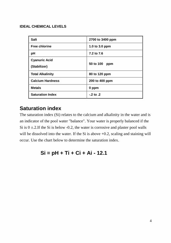
IDEAL CHEMICAL LEVELS
Salt 2700 to 3400 ppm
Free chlorine 1.0 to 3.0 ppm
pH 7.2 to 7.6
Cyanuric Acid
(Stabilizer)50 to 100 ppm
Total Alkalinity 80 to 120 ppm
Calcium Hardness 200 to 400 ppm
Metals 0 ppm
Saturation Index -.2 to .2
Saturation indexThe saturation index (Si) relates to the calcium and alkalinity in the water and is
an indicator of the pool water "balance". Your water is properly balanced if the
Si is 0 ±.2.If the Si is below -0.2, the water is corrosive and plaster pool walls
will be dissolved into the water. If the Si is above +0.2, scaling and staining will
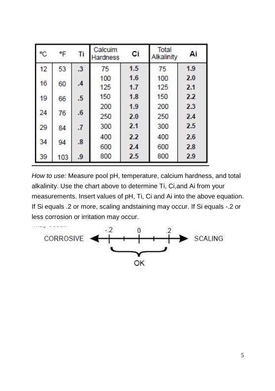
occur. Use the chart below to determine the saturation index.
Si = pH + Ti + Ci + Ai - 12.1
5
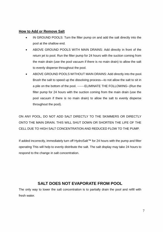
How to use: Measure pool pH, temperature, calcium hardness, and total
alkalinity. Use the chart above to determine Ti, Ci,and Ai from your
measurements. Insert values of pH, Ti, Ci and Ai into the above equation.
If Si equals .2 or more, scaling andstaining may occur. If Si equals -.2 or
less corrosion or irritation may occur.
6
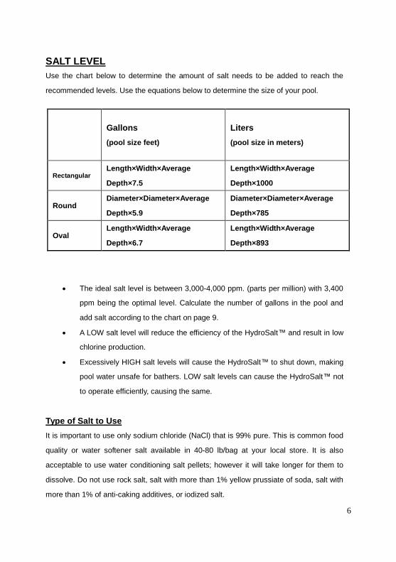
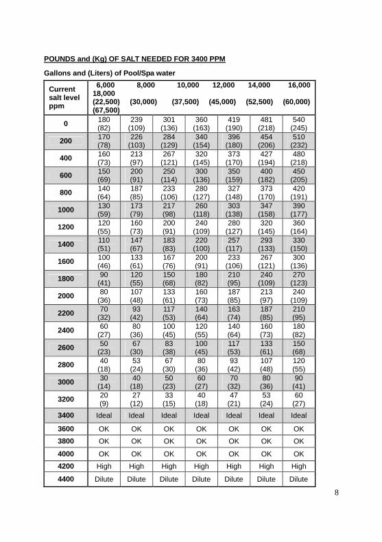
SALT LEVEL
Use the chart below to determine the amount of salt needs to be added to reach the
recommended levels. Use the equations below to determine the size of your pool.
The ideal salt level is between 3,000-4,000 ppm. (parts per million) with 3,400
ppm being the optimal level. Calculate the number of gallons in the pool and
add salt according to the chart on page 9.
A LOW salt level will reduce the efficiency of the HydroSalt™ and result in low
chlorine production.
Excessively HIGH salt levels will cause the HydroSalt™ to shut down, making
pool water unsafe for bathers. LOW salt levels can cause the HydroSalt™ not
to operate efficiently, causing the same.
Type of Salt to Use
It is important to use only sodium chloride (NaCl) that is 99% pure. This is common food
quality or water softener salt available in 40-80 lb/bag at your local store. It is also
acceptable to use water conditioning salt pellets; however it will take longer for them to
dissolve. Do not use rock salt, salt with more than 1% yellow prussiate of soda, salt with
more than 1% of anti-caking additives, or iodized salt.
Gallons
(pool size feet)
Liters
(pool size in meters)
RectangularLength×Width×Average
Depth×7.5
Length×Width×Average
Depth×1000
RoundDiameter×Diameter×Average
Depth×5.9
Diameter×Diameter×Average
Depth×785
OvalLength×Width×Average
Depth×6.7
Length×Width×Average
Depth×893
7
How to Add or Remove Salt
IN GROUND POOLS: Turn the filter pump on and add the salt directly into the
pool at the shallow end.
ABOVE GROUND POOLS WITH MAIN DRAINS: Add directly in front of the
return jet to pool. Run the filter pump for 24 hours with the suction coming from
the main drain (use the pool vacuum if there is no main drain) to allow the salt
to evenly disperse throughout the pool.
ABOVE GROUND POOLS WITHOUT MAIN DRAINS: Add directly into the pool.
Brush the salt to speed up the dissolving process—to not allow the salt to sit in
a pile on the bottom of the pool. -------ELIMINATE THE FOLLOWING--(Run the
filter pump for 24 hours with the suction coming from the main drain (use the
pool vacuum if there is no main drain) to allow the salt to evenly disperse
throughout the pool).
ON ANY POOL, DO NOT ADD SALT DIRECTLY TO THE SKIMMERS OR DIRECTLY
ONTO THE MAIN DRAIN. THIS WILL SHUT DOWN OR SHORTEN THE LIFE OF THE
CELL DUE TO HIGH SALT CONCENTRATION AND REDUCED FLOW TO THE PUMP.
If added incorrectly, immediately turn off HydroSalt™ for 24 hours with the pump and filter
operating This will help to evenly distribute the salt. The salt display may take 24 hours to
respond to the change in salt concentration.
SALT DOES NOT EVAPORATE FROM POOL
The only way to lower the salt concentration is to partially drain the pool and refill with
fresh water.
8
POUNDS and (Kg) OF SALT NEEDED FOR 3400 PPM
Gallons and (Liters) of Pool/Spa water
Currentsalt levelppm
6,000 8,000 10,000 12,000 14,000 16,00018,000(22,500) (30,000) (37,500) (45,000) (52,500) (60,000)(67,500)
0180(82)
239(109)
301(136)
360(163)
419(190)
481(218)
540(245)
200170(78)
226(103)
284(129)
340(154)
396(180)
454(206)
510(232)
400160(73)
213(97)
267(121)
320(145)
373(170)
427(194)
480(218)
600150(69)
200(91)
250(114)
300(136)
350(159)
400(182)
450(205)
800140(64)
187(85)
233(106)
280(127)
327(148)
373(170)
420(191)
1000130(59)
173(79)
217(98)
260(118)
303(138)
347(158)
390(177)
1200120(55)
160(73)
200(91)
240(109)
280(127)
320(145)
360(164)
1400110(51)
147(67)
183(83)
220(100)
257(117)
293(133)
330(150)
1600100(46)
133(61)
167(76)
200(91)
233(106)
267(121)
300(136)
180090
(41)120(55)
150(68)
180(82)
210(95)
240(109)
270(123)
200080
(36)107(48)
133(61)
160(73)
187(85)
213(97)
240(109)
220070
(32)93
(42)117(53)
140(64)
163(74)
187(85)
210(95)
240060
(27)80
(36)100(45)
120(55)
140(64)
160(73)
180(82)
260050
(23)67
(30)83
(38)100(45)
117(53)
133(61)
150(68)
280040
(18)53
(24)67
(30)80
(36)93
(42)107(48)
120(55)
300030
(14)40
(18)50
(23)60
(27)70
(32)80
(36)90
(41)
320020(9)
27(12)
33(15)
40(18)
47(21)
53(24)
60(27)
3400 Ideal Ideal Ideal Ideal Ideal Ideal Ideal
3600 OK OK OK OK OK OK OK
3800 OK OK OK OK OK OK OK
4000 OK OK OK OK OK OK OK
4200 High High High High High High High
4400 Dilute Dilute Dilute Dilute Dilute Dilute Dilute

9
STABILIZER (CYANURIC ACID)
Always test for stabilizer (cyanuric acid) level, when testing for salt. This test should be
done at least once per month. Use the chart below to determine how much stabilizer must
be added to raise the level to 80 ppm .
POUNDS and (Kg) OF STABILIZER (CYANURIC ACID) NEEDED FOR 80 PPM
Gallons and (Liters) of Pool/Spa water
CurrentStabilizer
Level(ppm)
6,000(22500)
8,000(30000)
10,000(37500)
12,000(45000)
14,000(52500)
16,000(60000)
18,000(67500)
0 ppm4.0
(1.8)5.3
(2.4)6.7
(3.0)8.0
(3.6)9.4
(4.3)10.7(4.9)
12.0(5.4)
10 ppm3.5
(1.6)4.7
(2.1)5.8
(2.6)7.0
(3.2)8.2
(3.7)9.4
(4.3)10.5(4.8)
20 ppm3.0
(1.4)4.0
(1.8)5.0
(2.3)6.0
(2.7)7.0
(3.2)8.0
(3.6)9.0
(2.2)
30 ppm2.5
(1.1)3.3
(1.5)4.2
(1.9)5.0
(2.3)5.9
(2.7)6.7
(3.0)7.5
(3.4)
40 ppm2.0(.9)
2.7(1.2)
3.3(1.5)
4.0(1.8)
4.7(2.1)
5.4(2.4)
6.0(2.7)
50 ppm1.5(.7)
2.0(.9)
2.5(1.1)
3.0(1.4)
3.5(1.6)
4.0(1.8)
4.5(2.0)
60 ppm1.0(.5)
1.3(.6)
1.7(.8)
2.0(.91)
2.4(1.1)
2.7(1.2)
3.0(1.4)
70 ppm0.5(.2)
0.7(.3)
0.8(.4)
1.0(.45)
1.2(.54)
1.4(.64)
1.5(.68)
80 ppm 0.0 0.0 0.0 0.0 0.0 0.0 0.0
10
POLYMERS:
It is advised to use polymers (commonly sold as poly algaecide) on salt water sanitizing
systems. The poly algaecide is sold in 30% and 60% concentrations.
Application rate is 1 quart of Poly30 (or ½ quart of Poly 60) per 15,000 gallons (60,000
liters) of pool water, per month. Apply directly in front of the return jet.
CONTROLS
MAIN SWITCH
AUTO: For normal operation, the Main switch should be left in the AUTO
position. In this position the HydroSalt™ will produce chlorine according to the
“Desired Level %” adjustment setting for the entire filtering / pumping cycle.
SUPER CHLORINATE: When you have an abnormally high bather load, heavy
rainfall, cloudy water conditions, or any other condition which requires that a
large amount of purification be introduced, set the Main Switch in the SUPER
CHLORINATE position. This electronically “super chlorinates” (shocks) the
water for 24 hours (filter pump must be on during this time) or until the power
has been turned off, whichever comes first. At the end of the super chlorination
period, be sure to put the switch back into the AUTO position.
OFF: The OFF position prevents the HydroSalt™ from energizing the
electrolytic cell. In this position there is no chlorine generation.
NOTE: In times of servicing, the OFF switch is not to be used. To service the HydroSalt™,
turn power off the circuit breaker.
DESIRED LEVEL ADJUSTMENT KNOB
This setting is used to control the amount of chlorine the HydroSalt™ generates. Adjust
this setting to increase or decrease the chlorine output level. The reading is from 5
percent output to 100% output capacity of the HydroSalt™.
11
INDICATOR LED
POWER: When illuminated, the HydroSalt™ has input power.
GENERATING: This LED is on steady during normal operation. When flashing,
the pool water is too hot or cold to operate.
SUPER CHLORINATE: Illuminates during Super Chlorination. See description
above.
REMOTE CONTROLLED: The part is controlled by a remote control system.
NO FLOW: When illuminated, the flow switch has detected no flow and
HydroSalt™ is NOT generating chlorine. A flashing LED indicates that the flow
is restored, but there will be a 60 second delay before generation is
re-established.
CHECK SALT: If flashing, the salt level is low (below 2500ppm) and
HydroSalt™ is generating at low efficiency. When illuminated steady, the salt
level is too low and HydroSalt™ has shut down.
Note: Before adding large quantities of salt, it is advisable to have your salt level
professionally checked.
HIGH SALT: When illuminated, the salt level is too high and HydroSalt™ has
shut down. The pool water must be diluted with fresh water before operation is
restored.
INSPECT CELL:
If flashing, either the cell efficiency is reduced or it is time for regularly
scheduled cell inspection. In either case, inspect the cell and clean if necessary.
Pressing the “diagnostic” button next to the display for 3 seconds will stop the
flashing LED.
When illuminated steady, cell efficiency is greatly reduced and HydroSalt™ has
stopped producing chlorine. Inspect, clean or replace if necessary.
SALT DISPLAY
The Salt Display shows the current salt concentration of the pool water. Readings are in
ppm (parts per million). If Metric units (grams per liter) are preferred, push the “diagnostic”
12
button next to the display once. The display will now show the pool water temperature in
degrees Fahrenheit. With the temperature displayed, move the main switch from AUTO to
SUPER CHLORINATE to AUTO. The temperature display will instantly change to
degrees Celsius. Repeat this process to switch back to USA units (Fahrenheit).
OPERATION
By familiarizing yourself with the operation of the HydroSalt™ generator, you can achieve
maximum performance for your pool. When chemical levels are in the recommended
range, there are FOUR factors that you can control which directly contribute to the
amount of chlorine the HydroSalt™ will generate:
Filter time each day (hours)
The amount of salt in the pool
The “Desired Level %” setting
Stabilizer level in the water.
To find the optimum “Desired Level %” setting, start at a fairly high setting and work
downward. It will take a few days of adjustments to find the ideal setting for your pool.
Once determined, it should only take minor adjustments. The HydroSalt™ control will not
produce chlorine at temperatures below 50’F If your pool water is colder than 50’F, you
must chlorinate manually.
Maintaining the Rx Clear™ HydroSalt™ Chlorine Generator
To maintain maximum performance, it is recommended that you remove and visually
inspect the cell every 3 months. The HydroSalt™ will remind you to do this by flashing the
“Inspect Cell” LED after approximately 500 hours of operation. After you inspect the cell
(and clean, if necessary) press the small “diagnostic” button next to the display for 3
seconds to stop the flashing “Inspect Cell” LED and start the timer for the next 500 hour
inspection period.
The HydroSalt™ electrolytic cell has a self-cleaning feature incorporated into the
electronic control’s logic. In most cases this self-cleaning action will keep the cell working
at optimum efficiency. In areas where water is hard (high calcium and/or mineral content)

13
and in pools where the water chemistry has gotten “out of balance”, the cell may require
periodic cleaning. The “Inspect Cell” LED remains on after a thorough cleaning, the cell
may be worn and may require replacement.
Servicing and Cleaning the cell
Turn off power to the HydroSalt™ before removing the CELL.
Once removed, look inside the cell and inspect for scale formation (light colored
crusty or flaky deposits) on the plates and for any debris that has passed
through the filter and got caught on the plates.
If no deposits are visible, re-install. If deposits are seen, use a high-pressure
garden hose and try to flush the scale off. If this is not successful, use a plastic
or wood tool to scrape deposits off of the plates.
Note: **DO NOT USE A METAL SCRAPER AS THIS WILL SCRATCH THE
FINISH AND DAMAGE THE PLATES.**
Buildup on the cell indicates that there is an unusually high calcium level in the
pool (old pool water is usually the cause). If this is not corrected, you will need
to clean the cell more frequently. The simplest way to avoid this is to bring the
pool chemistry to recommended levels, as specified.
Mild Acid Washing:
Use only in severe cases where flushing and scraping will not remove the majority of
deposits. To acid wash:
Turn off power to HydroSalt™.
Remove cell from piping.
In a clean plastic container, carefully mix a 4:1 solution of water to muriatic acid
(one gallon of water to one quart of muriatic acid).

14
WARNING :
ALWAYS POUR ACID INTO WATER-NEVER POUR WATER INTO ACID.
BE SURE TO WEAR PROTECTIVE GLASSES, CLOTHING AND CHEMICAL
RESISTANT GLOVES
The level of the solution in the container should just reach the top of the cell so
that the wire harness compartment is NOT submerged. It may be helpful to coil
the wiring before immersing the cell.
The cell should soak for FIVE minutes, then rinse with a high-pressure garden
hose.
If any deposits are still visible, repeat soaking and rinsing.
Replace cell and inspect again periodically.
Winterizing
The HydroSalt™ electrolytic cell and flow detection switch will be damaged by freezing
water, similar to other pool components that require proper winterization. In areas of the
country that experience severe or extended periods of freezing temperatures, be sure to
drain all water from the pump, filter, and supply and return lines before any freezing
conditions occur. The electronic control is capable of withstanding any winter weather and
should not be removed.
Spring Start-up
DO NOT turn HydroSalt™ on, until the pool water chemistry has been balanced to proper
levels.
15
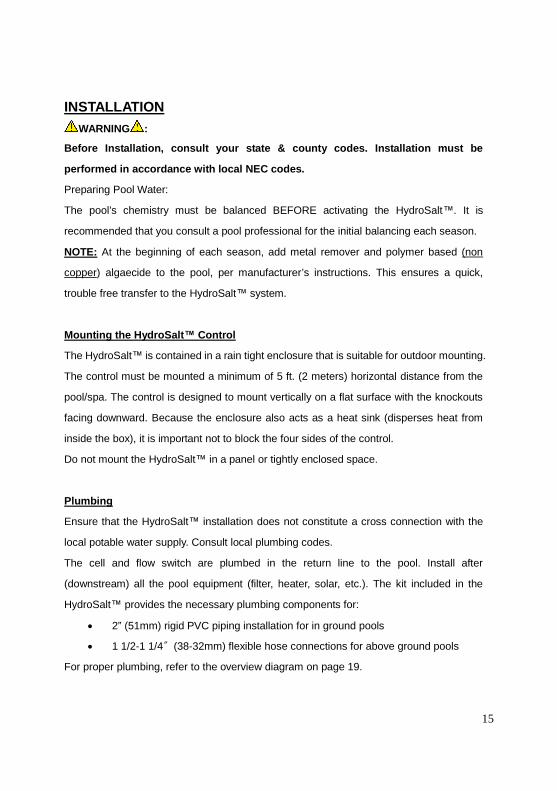
INSTALLATION
WARNING :
Before Installation, consult your state & county codes. Installation must be
performed in accordance with local NEC codes.
Preparing Pool Water:
The pool’s chemistry must be balanced BEFORE activating the HydroSalt™. It is
recommended that you consult a pool professional for the initial balancing each season.
NOTE: At the beginning of each season, add metal remover and polymer based (non
copper) algaecide to the pool, per manufacturer’s instructions. This ensures a quick,
trouble free transfer to the HydroSalt™ system.
Mounting the HydroSalt™ Control
The HydroSalt™ is contained in a rain tight enclosure that is suitable for outdoor mounting.
The control must be mounted a minimum of 5 ft. (2 meters) horizontal distance from the
pool/spa. The control is designed to mount vertically on a flat surface with the knockouts
facing downward. Because the enclosure also acts as a heat sink (disperses heat from
inside the box), it is important not to block the four sides of the control.
Do not mount the HydroSalt™ in a panel or tightly enclosed space.
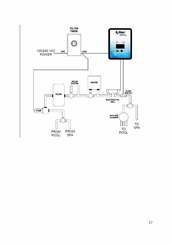
Plumbing
Ensure that the HydroSalt™ installation does not constitute a cross connection with the
local potable water supply. Consult local plumbing codes.
The cell and flow switch are plumbed in the return line to the pool. Install after
(downstream) all the pool equipment (filter, heater, solar, etc.). The kit included in the
HydroSalt™ provides the necessary plumbing components for:
2” (51mm) rigid PVC piping installation for in ground pools
1 1/2-1 1/4〞(38-32mm) flexible hose connections for above ground pools
For proper plumbing, refer to the overview diagram on page 19.
16
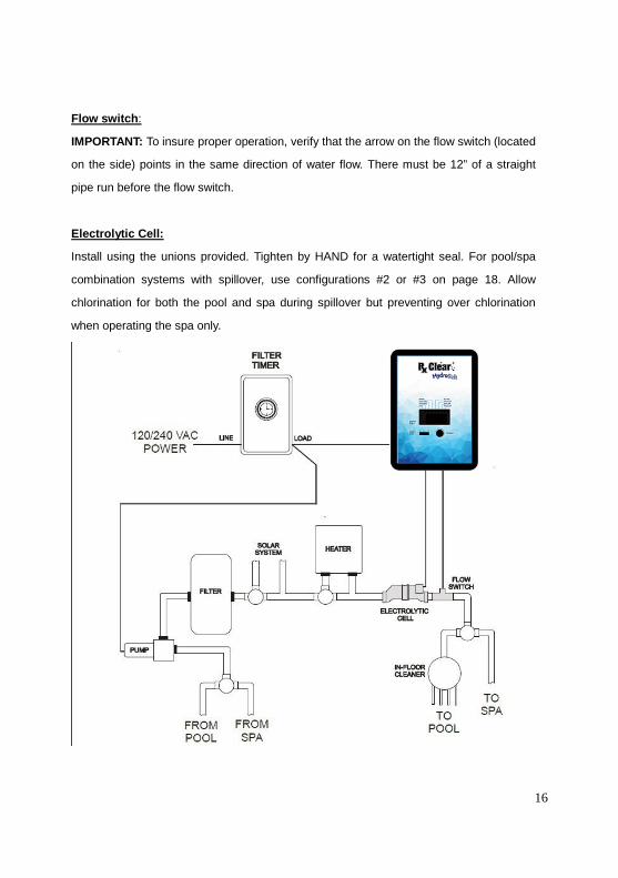
Flow switch:
IMPORTANT: To insure proper operation, verify that the arrow on the flow switch (located
on the side) points in the same direction of water flow. There must be 12” of a straight
pipe run before the flow switch.
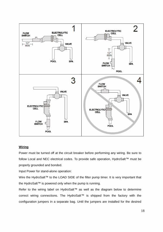
Electrolytic Cell:
Install using the unions provided. Tighten by HAND for a watertight seal. For pool/spa
combination systems with spillover, use configurations #2 or #3 on page 18. Allow
chlorination for both the pool and spa during spillover but preventing over chlorination
when operating the spa only.
17
18
Wiring
Power must be turned off at the circuit breaker before performing any wiring. Be sure to
follow Local and NEC electrical codes. To provide safe operation, HydroSalt™ must be
properly grounded and bonded.
Input Power for stand-alone operation:
Wire the HydroSalt™ to the LOAD SIDE of the filter pump timer. It is very important that
the HydroSalt™ is powered only when the pump is running.
Refer to the wiring label on HydroSalt™ as well as the diagram below to determine
correct wiring connections. The HydroSalt™ is shipped from the factory with the
configuration jumpers in a separate bag. Until the jumpers are installed for the desired

19
voltage, the unit should NOT be turned on.
For Canadian models, the HydroSalt™ shall be connected to a circuit protected
by a class A ground fault interrupter. Be sure to connect the GROUND wire to
the green ground screw terminal located on the INSIDE WALL of the enclosure.
Note: Wire the pump directly to the time clock—do not use the HydroSalt™ as a junction
box.

20
Bonding:
A lug used for bonding is attached to the bottom of the HydroSalt™ enclosure (see
diagram below). The HydroSalt™ must be bonded with an 8 AWG copper wire (6 AWG
Canada) to the pool bonding system.
Electrolytic Cell and Flow Switch:
The electrolytic cell and flow switch cables are terminated with connectors that plug into
the HydroSalt™ for easy attachment and removal. The door of the HydroSalt™ must be
open to access the cell cable connector. The flow switch plugs into a connector (similar to
a telephone jack) located outside, on the bottom of the enclosure. Refer to the diagram
below for the location of these connections.
Input power for use with Hayward/Goldline, Pentair and Polaris controls:
Wire the HydroSalt™® DIRECTLY TO 120/240vac POWER (not through timer or relay).
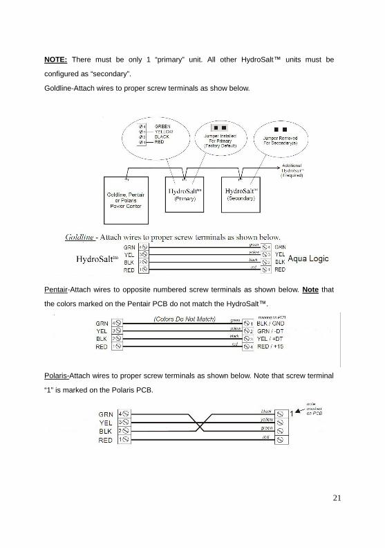
Optional Goldline, Pentair and Polaris controls:
The Goldline, Pentair and Polaris controls use a 4 wire connection to communicate to the
HydroSalt™ and can be wire up to 500’ apart. Any outdoor rated 4 conductor cable can be
used. Refer to each manufacturer’s instructions and the wiring diagrams below for proper
wiring connection to the HydroSalt™.
21
NOTE: There must be only 1 “primary” unit. All other HydroSalt™ units must be
configured as “secondary”.
Goldline-Attach wires to proper screw terminals as show below.
Pentair-Attach wires to opposite numbered screw terminals as shown below. Note that
the colors marked on the Pentair PCB do not match the HydroSalt™.
Polaris-Attach wires to proper screw terminals as shown below. Note that screw terminal
“1” is marked on the Polaris PCB.
22
TROUBLESHOOTING
Diagnostic Displays
Sequential pushes of the small “diagnostic” button next to the LCD display will cause the
HydroSalt™ to display the following information:
1. Pool temperature (xx degrees Fahrenheit or Celsius)
2. Cell voltage (typically 21.0 to 27.0 volts when chlorine is being generated,
otherwise 16-25V )
3. Cell current (typically 2.50 to 7.80 amps when chlorine is being generated,
otherwise 0 amps)
4. Desired Output% (“0P”—“100P”depending on knob position)
5. Instant salinity (-xxxx ppm or-x.xx grams/Liter)
6. Product name sent to the display
7. Software revision level
8. Cell type
On the 9th push of the button the display will revert back to the default salt display. Also if
the button is not pushed for 30 seconds, the display will revert back default salt.
Common Problems and Solutions
1. “Power” LED not on
Check to make sure 120 / 240 VAC input power is connected to the control. Be sure the
jumpers are set properly. Verify input voltage with a voltmeter. If there is input power, the
fuse may have blown. The board is protected by a 20 amp mini ATO fuse located on the
circuit board above the cell connector.
2. "Generating" LED flashing
The temperature of the pool water is too high or low to operate. You can override this by
switching the main switch to SUPER CHLORINATE. The HydroSalt™ will run at
maximum output for the remainder of the current pump cycle or 24 hours, whichever
comes first.
3. "No Flow" LED illuminated or flashing
The HydroSalt™ has sensed a no flow condition and has stopped generating chlorine.
23
Check that the flow switch is plugged into the connector on the bottom of the control unit
and that the wire is not cut or damaged. Make sure you have at least 12" of straight pipe
before the flow switch. If there is adequate flow and the LED is still on, check that the
arrows on the flow switch (on top of hex) are pointing in the direction of flow. If the light is
flashing, the flow is established and the HydroSalt™ will turn on within 1 minute.
4. "Check Salt" LED illuminated or flashing
Check salt level in pool/spa. If salt level is low, add salt according to chart on page 8.
Before adding large quantities of salt, it is advisable to have your salt level professionally
checked.
5. "High Salt" LED illuminated
Check salt level in pool/spa. If salt level is too high, lower salt level by draining some of
the pool water out of the pool and replace with fresh water. Continue until the salt
concentration is at recommended levels.
6. “Inspect Cell” LED flashing
Inspect and clean cell according to directions. (see page 12-14) When done, press the
“diagnostic” button for 3 seconds to stop the “Inspect Cell” LED flashing.
7. “Inspect Cell” LED illuminated
Remove and inspect the cell for scale. If the cell is scaled, follow the directions on page 8
for cell cleaning. If the pool has the proper amount of salt and the “Inspect Cell” LED is
still illuminated, the cell may be depleted and needs to be replaced.
8. Possible causes of low chlorine or no chlorine
HydroSalt™ switch in OFF position.
Desired Level% adjustment setting is too low.
Low stabilizer (Cyanuric Acid).Chlorine is being produced but the pool water is
unable to hold on to the chlorine, due to low stabilizer.
Filter pump switched off or filter pump time too short (8 hours for average size
pools, more for large pools).
Salt level too low (below 2500 ppm, Low Salt LED on).
Salt level too high (high Salt LED on).
24
Low pH. Low pH oxidizes chlorine quickly, making it difficult to maintain desired
chlorine levels. Adjust pH levels to re-balance water.
Warm pool water increases chlorine demand—increase Desired Level% or
filter run time.
Cold water (below 50F) can cause HydroSalt™ to stop generating (Generating
LED flashing).
Excessive scaling on cell.
High level of phosphates in pool water.
Some yellow algae treatments will use chlorine at a very high rate and deplete
the residual free chlorine. Manually shock the pool if indicated in the directions
on the algae treatment. It still may be a matter of days before the pool returns to
“normal” and chlorine tests will show the desired 1-3ppm free chlorine reading.
9. “PCB” displayed and all 4 LEDs are illuminated.
A possible printed circuit board fault has been detected. Call for service.
REPLACEMENT PART LIST
Item No. Part description

25
Two (2) Year Limited Warranty
RxClear™ (HydroSalt™) is warranted to be free from defects in materials
and workmanship, under normal use and non-commercial application, for
a period of Two (2) years from date of purchase, per the schedule below.
To obtain service, contact the authorized dealer from which the unit was
purchased. Proof of purchase may be required. This limited warranty is
extended exclusively to the original purchaser of the HydroSalt™ system
and is non-transferable. HydroSalt™ is intended for residential pool use
and any commercial application voids all warranties.
Two (2) year warranty for power cell and generating cell.
One (1) year warranty on components.
Exclusions from warranty coverage:
Problems arising from failure to maintain proper water chemistry
levels, per manufacturer’s recommendations, as outlined in the
Owner’s Manual.
Problems arising from failure to use HydroSalt™ in accordance
with manufacturer’s recommendations, as outlined in the Owner’s
Manual.
Problems resulting from tampering, accident, electrical surges,
abuse, neglect, unauthorized or unqualified repairs, product
alteration, fire, flood, freeze damage, acts of nature.
Damage or degrading of concrete, natural stone, wood or
synthetic surfaces adjacent to the swimming pool or spa.
Problems or damages incurred due to improper installation and/or
improper electrical supply.
26
Millstream Distribution LLC is not responsible for any labor charges, loss of
water or any damages that may occur. The purchaser is responsible for all
shipping and handling fees for the replacement and/or replacement parts
covered by this warranty.
This Warranty provides the exclusive remedy for any damages, including
direct, consequential, special or incidental loss or damage. This warranty gives
you specific legal rights. You may have other rights, which may vary from
state to state.


