311911EEN
Repair
FinishPro 390/395 Airless/Air-Assisted Sprayer
- For the application of architectural paints and coatings -
Maximum Fluid Working Pressure: 3300 psi (227 bar, 22.7 MPa)
Maximum Air Working Pressure: 35 psi (2.4 bar, 0.24 MPa)
Models:
Related Manuals:
Australian Patent No. 2004313479
IMPORTANT SAFETY INSTRUCTIONS! Read all warnings and instructions. Save these instructions. Contact Graco Customer Ser-vice, your local Graco distributor or our website: www.graco.com, to obtain a manual in your lan-guage.
Region FinishPro 390 FinishPro 395
US 249690 249691
Europe CEE 7/7 255110 255111
Europe Multi Cord 255112 255113
UK 255114 255115
Asia/Australia 255116 255117
311905 311937
309250 312100 FinishPro 390
ti9019a
ti9026a
FinishPro 395
Warning
2 311911E
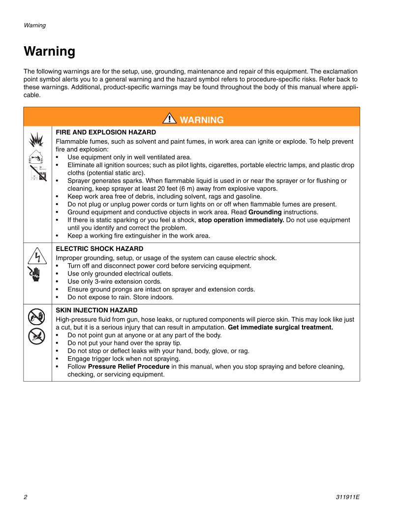
WarningThe following warnings are for the setup, use, grounding, maintenance and repair of this equipment. The exclamation point symbol alerts you to a general warning and the hazard symbol refers to procedure-specific risks. Refer back to these warnings. Additional, product-specific warnings may be found throughout the body of this manual where appli-cable.
WARNINGFIRE AND EXPLOSION HAZARD Flammable fumes, such as solvent and paint fumes, in work area can ignite or explode. To help prevent fire and explosion:• Use equipment only in well ventilated area.• Eliminate all ignition sources; such as pilot lights, cigarettes, portable electric lamps, and plastic drop
cloths (potential static arc). • Sprayer generates sparks. When flammable liquid is used in or near the sprayer or for flushing or
cleaning, keep sprayer at least 20 feet (6 m) away from explosive vapors.• Keep work area free of debris, including solvent, rags and gasoline.• Do not plug or unplug power cords or turn lights on or off when flammable fumes are present.• Ground equipment and conductive objects in work area. Read Grounding instructions.• If there is static sparking or you feel a shock, stop operation immediately. Do not use equipment
until you identify and correct the problem.• Keep a working fire extinguisher in the work area.
ELECTRIC SHOCK HAZARD Improper grounding, setup, or usage of the system can cause electric shock.• Turn off and disconnect power cord before servicing equipment.• Use only grounded electrical outlets.• Use only 3-wire extension cords.• Ensure ground prongs are intact on sprayer and extension cords.• Do not expose to rain. Store indoors.
SKIN INJECTION HAZARD High-pressure fluid from gun, hose leaks, or ruptured components will pierce skin. This may look like just a cut, but it is a serious injury that can result in amputation. Get immediate surgical treatment.• Do not point gun at anyone or at any part of the body.• Do not put your hand over the spray tip.• Do not stop or deflect leaks with your hand, body, glove, or rag.• Engage trigger lock when not spraying.• Follow Pressure Relief Procedure in this manual, when you stop spraying and before cleaning,
checking, or servicing equipment.
Warning
311911E 3
WARNING
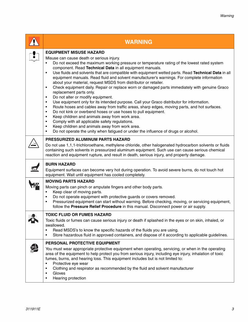
EQUIPMENT MISUSE HAZARDMisuse can cause death or serious injury.• Do not exceed the maximum working pressure or temperature rating of the lowest rated system
component. Read Technical Data in all equipment manuals.• Use fluids and solvents that are compatible with equipment wetted parts. Read Technical Data in all
equipment manuals. Read fluid and solvent manufacturer’s warnings. For complete information about your material, request MSDS from distributor or retailer.
• Check equipment daily. Repair or replace worn or damaged parts immediately with genuine Graco replacement parts only.
• Do not alter or modify equipment.• Use equipment only for its intended purpose. Call your Graco distributor for information.• Route hoses and cables away from traffic areas, sharp edges, moving parts, and hot surfaces.• Do not kink or overbend hoses or use hoses to pull equipment.• Keep children and animals away from work area.• Comply with all applicable safety regulations.• Keep children and animals away from work area.• Do not operate the unity when fatigued or under the influence of drugs or alcohol.
PRESSURIZED ALUMINUM PARTS HAZARD Do not use 1,1,1-trichloroethane, methylene chloride, other halogenated hydrocarbon solvents or fluids containing such solvents in pressurized aluminum equipment. Such use can cause serious chemical reaction and equipment rupture, and result in death, serious injury, and property damage.
BURN HAZARDEquipment surfaces can become very hot during operation. To avoid severe burns, do not touch hot equipment. Wait until equipment has cooled completely.
MOVING PARTS HAZARD Moving parts can pinch or amputate fingers and other body parts.• Keep clear of moving parts.• Do not operate equipment with protective guards or covers removed.• Pressurized equipment can start without warning. Before checking, moving, or servicing equipment,
follow the Pressure Relief Procedure in this manual. Disconnect power or air supply.
TOXIC FLUID OR FUMES HAZARD Toxic fluids or fumes can cause serious injury or death if splashed in the eyes or on skin, inhaled, or swallowed.• Read MSDS’s to know the specific hazards of the fluids you are using.• Store hazardous fluid in approved containers, and dispose of it according to applicable guidelines.
PERSONAL PROTECTIVE EQUIPMENT You must wear appropriate protective equipment when operating, servicing, or when in the operating area of the equipment to help protect you from serious injury, including eye injury, inhalation of toxic fumes, burns, and hearing loss. This equipment includes but is not limited to:• Protective eye wear • Clothing and respirator as recommended by the fluid and solvent manufacturer• Gloves• Hearing protection
Component Identification
4 311911E
Component Identification
ti9018a
ti9021a
FinishPro 395
11
10 9 8 13
7
12
5
6
4
3
1
2
15
10
9
4
6
11
8
3
2
1
14
5
7
FinishPro 390
16
12
17
18
1718
2019
19 20
21
Component Identification
311911E 5
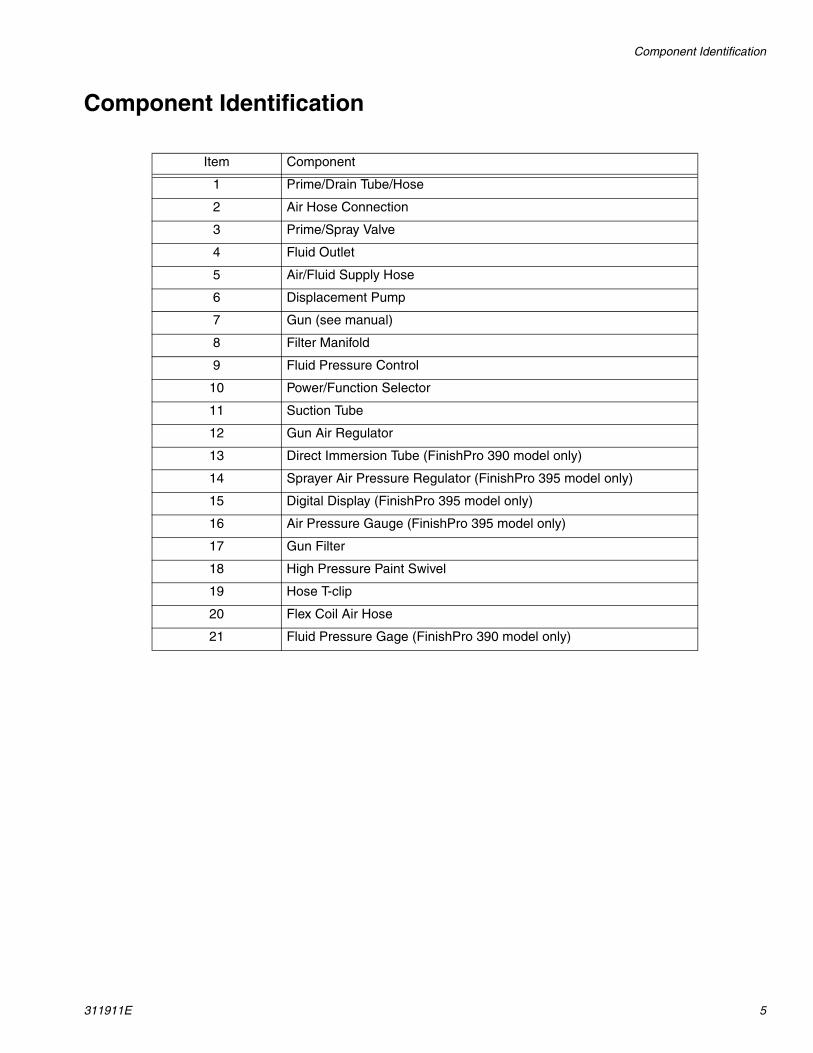
Component Identification
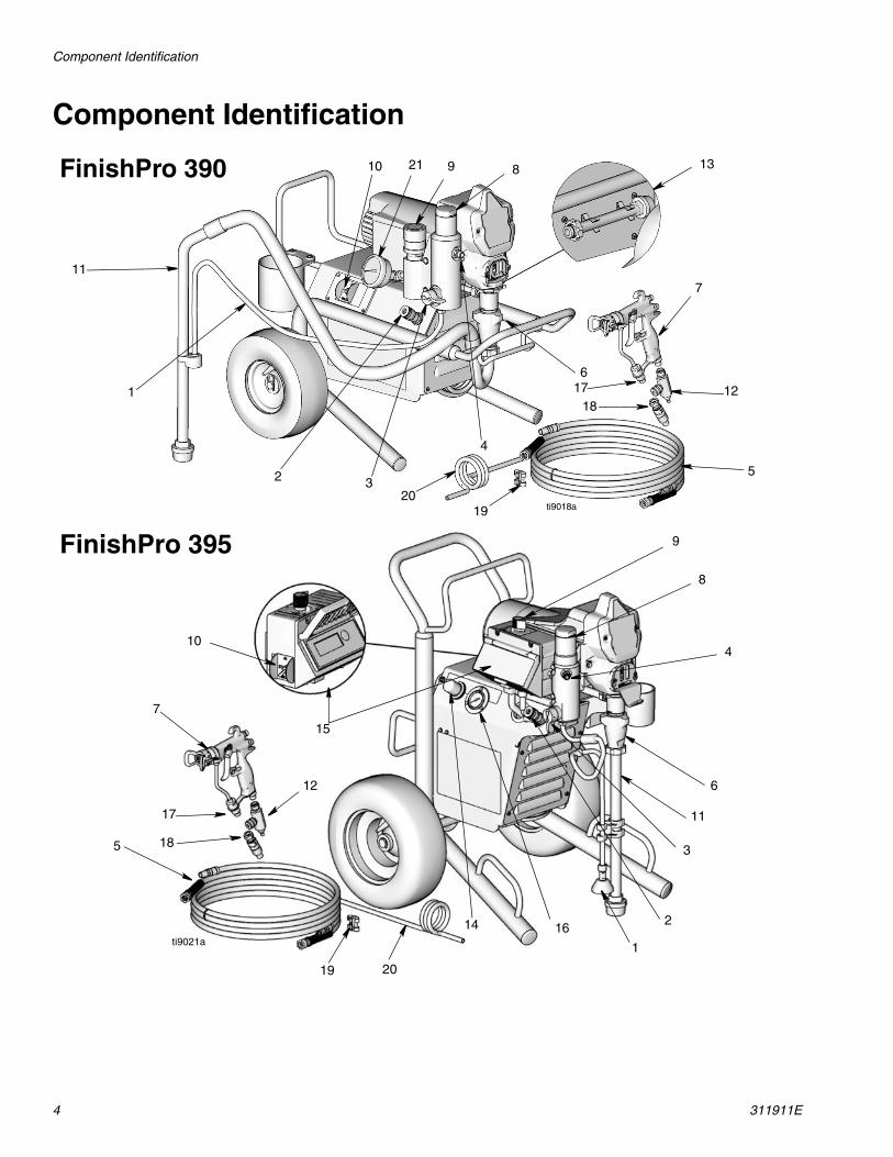
Item Component
1 Prime/Drain Tube/Hose
2 Air Hose Connection
3 Prime/Spray Valve
4 Fluid Outlet
5 Air/Fluid Supply Hose
6 Displacement Pump
7 Gun (see manual)
8 Filter Manifold
9 Fluid Pressure Control
10 Power/Function Selector
11 Suction Tube
12 Gun Air Regulator
13 Direct Immersion Tube (FinishPro 390 model only)
14 Sprayer Air Pressure Regulator (FinishPro 395 model only)
15 Digital Display (FinishPro 395 model only)
16 Air Pressure Gauge (FinishPro 395 model only)
17 Gun Filter
18 High Pressure Paint Swivel
19 Hose T-clip
20 Flex Coil Air Hose
21 Fluid Pressure Gage (FinishPro 390 model only)

Installation
6 311911E
InstallationGrounding and Electric Requirements
The sprayer cord includes a grounding wire with an appropriate grounding contact.
The sprayer requires: 110-120 Vac Sprayers: 100-120 Vac, 50/60 Hz, 15A, 1 phase, circuit with a grounding receptacle.
230 Vac Sprayers: 230 Vac, 50/60 Hz, 10A, 1 phase, cir-cuit with a grounding receptacle.
Never use an outlet that is not grounded or an adapter.
Do not use the sprayer if the electrical cord has a dam-aged ground contact. Only use an extension cord with an undamaged ground contact.
Recommended extension cords for use with this sprayer:
• 3-wire, 12 AWG (2.5 mm2) minimum, 300 ft. (90 m) maximum length.
NOTE: Smaller gauge or longer extension cords may reduce sprayer performance.
Spray gun: ground through connection to a properly grounded fluid hose and pump.
Fluid supply container: follow local code.
Solvent and Oil-based fluids: follow local code. Use only conductive metal pails placed on a grounded sur-face such as concrete. Do not place the pail on a non-conductive surface such as paper or cardboard, which interrupts grounding continuity.
Grounding the metal pail: connect a ground wire to the pail by clamping one end to pail and other end to ground such as a water pipe.
To maintain grounding continuity when flushing or relieving pressure: hold metal part of the spray gun firmly to the side of a grounded metal pail, then trigger the gun.
ti9590a
ti5573a
ti4297a
ti4297a
ti9270a
Pressure Relief Procedure
311911E 7
Pressure Relief Procedure
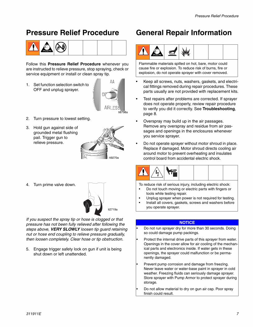
Follow this Pressure Relief Procedure whenever youare instructed to relieve pressure, stop spraying, check orservice equipment or install or clean spray tip.
1. Set function selection switch to OFF and unplug sprayer.
2. Turn pressure to lowest setting.
3. Hold gun against side of grounded metal flushing pail. Trigger gun to relieve pressure.
4. Turn prime valve down.
If you suspect the spray tip or hose is clogged or that pressure has not been fully relieved after following the steps above, VERY SLOWLY loosen tip guard retaining nut or hose end coupling to relieve pressure gradually, then loosen completely. Clear hose or tip obstruction.
5. Engage trigger safety lock on gun if unit is being shut down or left unattended.
General Repair Information
• Keep all screws, nuts, washers, gaskets, and electri-cal fittings removed during repair procedures. These parts usually are not provided with replacement kits.
• Test repairs after problems are corrected. If sprayer does not operate properly, review repair procedure to verify you did it correctly. See Troubleshooting, page 8.
• Overspray may build up in the air passages. Remove any overspray and residue from air pas-sages and openings in the enclosures whenever you service sprayer.
• Do not operate sprayer without motor shroud in place. Replace if damaged. Motor shroud directs cooling air around motor to prevent overheating and insulates control board from accidental electric shock.
ti8798a
ti9270a
ti2719a
Flammable materials spilled on hot, bare, motor could cause fire or explosion. To reduce risk of burns, fire or explosion, do not operate sprayer with cover removed.
To reduce risk of serious injury, including electric shock:• Do not touch moving or electric parts with fingers or
tools while testing repair. • Unplug sprayer when power is not required for testing. • Install all covers, gaskets, screws and washers before
you operate sprayer.
NOTICE• Do not run sprayer dry for more than 30 seconds. Doing
so could damage pump packings.
• Protect the internal drive parts of this sprayer from water. Openings in the cover allow for air cooling of the mechan-ical parts and electronics inside. If water gets in these openings, the sprayer could malfunction or be perma-nently damaged.
• Prevent pump corrosion and damage from freezing. Never leave water or water-base paint in sprayer in cold weather. Freezing fluids can seriously damage sprayer. Store sprayer with Pump Armor to protect sprayer during storage.
• Do not allow material to dry on gun air cap. Poor spray finish could result.
Troubleshooting
8 311911E
Troubleshooting
ProblemWhat To Check
(If check is OK, go to next check)What To Do
(When check is not OK, refer to this column)
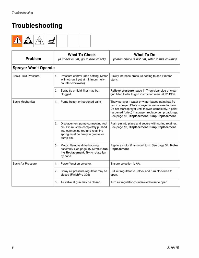
Sprayer Won’t Operate
Basic Fluid Pressure 1. Pressure control knob setting. Motor will not run if set at minimum (fully counter-clockwise).
Slowly increase pressure setting to see if motor starts.
2. Spray tip or fluid filter may be clogged.
Relieve pressure, page 7. Then clear clog or clean gun filter. Refer to gun instruction manual, 311937.
Basic Mechanical 1. Pump frozen or hardened paint Thaw sprayer if water or water-based paint has fro-zen in sprayer. Place sprayer in warm area to thaw. Do not start sprayer until thawed completely. If paint hardened (dried) in sprayer, replace pump packings. See page 13, Displacement Pump Replacement.
2. Displacement pump connecting rod pin. Pin must be completely pushed into connecting rod and retaining spring must be firmly in groove or pump pin.
Push pin into place and secure with spring retainer. See page 13, Displacement Pump Replacement.
3. Motor. Remove drive housing assembly. See page 15, Drive Hous-ing Replacement. Try to rotate fan by hand.
Replace motor if fan won’t turn. See page 34, Motor Replacement.
Basic Air Pressure 1. Power/function selector. Ensure selection is AA.
2. Spray air pressure regulator may be closed (FinishPro 395)
Pull air regulator to unlock and turn clockwise to open.
3. Air valve at gun may be closed Turn air regulator counter-clockwise to open.
Troubleshooting
311911E 9
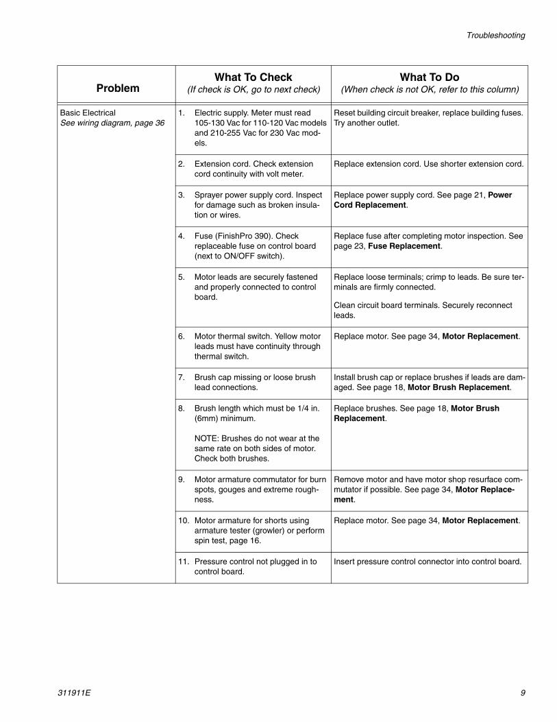
Basic ElectricalSee wiring diagram, page 36
1. Electric supply. Meter must read 105-130 Vac for 110-120 Vac models and 210-255 Vac for 230 Vac mod-els.
Reset building circuit breaker, replace building fuses. Try another outlet.
2. Extension cord. Check extension cord continuity with volt meter.
Replace extension cord. Use shorter extension cord.
3. Sprayer power supply cord. Inspect for damage such as broken insula-tion or wires.
Replace power supply cord. See page 21, Power Cord Replacement.
4. Fuse (FinishPro 390). Check replaceable fuse on control board (next to ON/OFF switch).
Replace fuse after completing motor inspection. See page 23, Fuse Replacement.
5. Motor leads are securely fastened and properly connected to control board.
Replace loose terminals; crimp to leads. Be sure ter-minals are firmly connected.
Clean circuit board terminals. Securely reconnect leads.
6. Motor thermal switch. Yellow motor leads must have continuity through thermal switch.
Replace motor. See page 34, Motor Replacement.
7. Brush cap missing or loose brush lead connections.
Install brush cap or replace brushes if leads are dam-aged. See page 18, Motor Brush Replacement.
8. Brush length which must be 1/4 in. (6mm) minimum.
NOTE: Brushes do not wear at the same rate on both sides of motor. Check both brushes.
Replace brushes. See page 18, Motor Brush Replacement.
9. Motor armature commutator for burn spots, gouges and extreme rough-ness.
Remove motor and have motor shop resurface com-mutator if possible. See page 34, Motor Replace-ment.
10. Motor armature for shorts using armature tester (growler) or perform spin test, page 16.
Replace motor. See page 34, Motor Replacement.
11. Pressure control not plugged in to control board.
Insert pressure control connector into control board.
ProblemWhat To Check
(If check is OK, go to next check)What To Do
(When check is not OK, refer to this column)
Troubleshooting
10 311911E
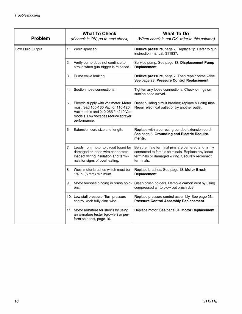
Low Fluid Output 1. Worn spray tip. Relieve pressure, page 7. Replace tip. Refer to gun instruction manual, 311937.
2. Verify pump does not continue to stroke when gun trigger is released.
Service pump. See page 13, Displacement Pump Replacement.
3. Prime valve leaking. Relieve pressure, page 7. Then repair prime valve. See page 28, Pressure Control Replacement.
4. Suction hose connections. Tighten any loose connections. Check o-rings on suction hose swivel.
5. Electric supply with volt meter. Meter must read 105-130 Vac for 110-120 Vac models and 210-255 for 240 Vac models. Low voltages reduce sprayer performance.
Reset building circuit breaker; replace building fuse. Repair electrical outlet or try another outlet.
6. Extension cord size and length. Replace with a correct, grounded extension cord. See page 6, Grounding and Electric Require-ments.
7. Leads from motor to circuit board for damaged or loose wire connectors. Inspect wiring insulation and termi-nals for signs of overheating.
Be sure male terminal pins are centered and firmly connected to female terminals. Replace any loose terminals or damaged wiring. Securely reconnect terminals.
8. Worn motor brushes which must be 1/4 in. (6 mm) minimum.
Replace brushes. See page 18. Motor Brush Replacement.
9. Motor brushes binding in brush hold-ers.
Clean brush holders. Remove carbon dust by using compressed air to blow out brush dust.
10. Low stall pressure. Turn pressure control knob fully clockwise.
Replace pressure control assembly. See page 28, Pressure Control Assembly Replacement.
11. Motor armature for shorts by using an armature tester (growler) or per-form spin test, page 16.
Replace motor. See page 34, Motor Replacement.
ProblemWhat To Check
(If check is OK, go to next check)What To Do
(When check is not OK, refer to this column)
Troubleshooting
311911E 11
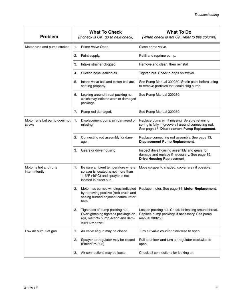
Motor runs and pump strokes 1. Prime Valve Open. Close prime valve.
2. Paint supply. Refill and reprime pump.
3. Intake strainer clogged. Remove and clean, then reinstall.
4. Suction hose leaking air. Tighten nut. Check o-rings on swivel.
5. Intake valve ball and piston ball are seating properly.
See Pump Manual 309250. Strain paint before using to remove particles that could clog pump.
6. Leaking around throat packing nut which may indicate worn or damaged packings.
See Pump Manual 309250.
7. Pump rod damaged. See Pump Manual 309250.
Motor runs but pump does not stroke
1. Displacement pump pin damaged or missing.
Replace pump pin if missing. Be sure retaining spring is fully in groove all around connecting rod. See page 13, Displacement Pump Replacement.
2. Connecting rod assembly for dam-age.
Replace connecting rod assembly. See page 13, Displacement Pump Replacement.
3. Gears or drive housing. Inspect drive housing assembly and gears for damage and replace if necessary. See page 15, Drive Housing Replacement.
Motor is hot and runs intermittently
1. Be sure ambient temperature where sprayer is located is not more than 115°F (46°C) and sprayer is not located in direct sun.
Move sprayer to shaded, cooler area if possible.
2. Motor has burned windings indicated by removing positive (red) brush and seeing burned adjacent commutator bars.
Replace motor. See page 34, Motor Replacement.
3. Tightness of pump packing nut. Overtightening tightens packings on rod, restricts pump action and dam-ages packings.
Loosen packing nut. Check for leaking around throat. Replace pump packings if necessary. See pump manual 309250.
Low air output at gun 1. Air valve at gun may be closed. Turn air valve counter-clockwise to open.
2. Sprayer air regulator may be closed (FinishPro 395)
Pull to unlock and turn air regulator clockwise to open.
3. Air connections may be loose. Check all connections for leaking air.
ProblemWhat To Check
(If check is OK, go to next check)What To Do
(When check is not OK, refer to this column)
Troubleshooting
12 311911E
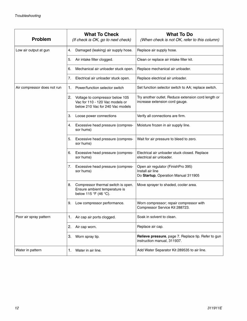
Low air output at gun 4. Damaged (leaking) air supply hose. Replace air supply hose.
5. Air intake filter clogged. Clean or replace air intake filter kit.
6. Mechanical air unloader stuck open. Replace mechanical air unloader.
7. Electrical air unloader stuck open. Replace electrical air unloader.
Air compressor does not run 1. Power/function selector switch Set function selector switch to AA; replace switch.
2. Voltage to compressor below 105 Vac for 110 - 120 Vac models or below 210 Vac for 240 Vac models
Try another outlet. Reduce extension cord length or increase extension cord gauge.
3. Loose power connections Verify all connections are firm.
4. Excessive head pressure (compres-sor hums)
Moisture frozen in air supply line.
5. Excessive head pressure (compres-sor hums)
Wait for air pressure to bleed to zero.
6. Excessive head pressure (compres-sor hums)
Electrical air unloader stuck closed. Replace electrical air unloader.
7. Excessive head pressure (compres-sor hums)
Open air regulator (FinishPro 395)Install air lineDo Startup, Operation Manual 311905
8. Compressor thermal switch is open. Ensure ambient temperature is below 115 °F (46 °C).
Move sprayer to shaded, cooler area.
9. Low compressor performance. Worn compressor; repair compressor with Compressor Service Kit 288723.
Poor air spray pattern 1. Air cap air ports clogged. Soak in solvent to clean.
2. Air cap worn. Replace air cap.
3. Worn spray tip. Relieve pressure, page 7. Replace tip. Refer to gun instruction manual, 311937.
Water in pattern 1. Water in air line. Add Water Separator Kit 289535 to air line.
ProblemWhat To Check
(If check is OK, go to next check)What To Do
(When check is not OK, refer to this column)
Displacement Pump Replacement
311911E 13
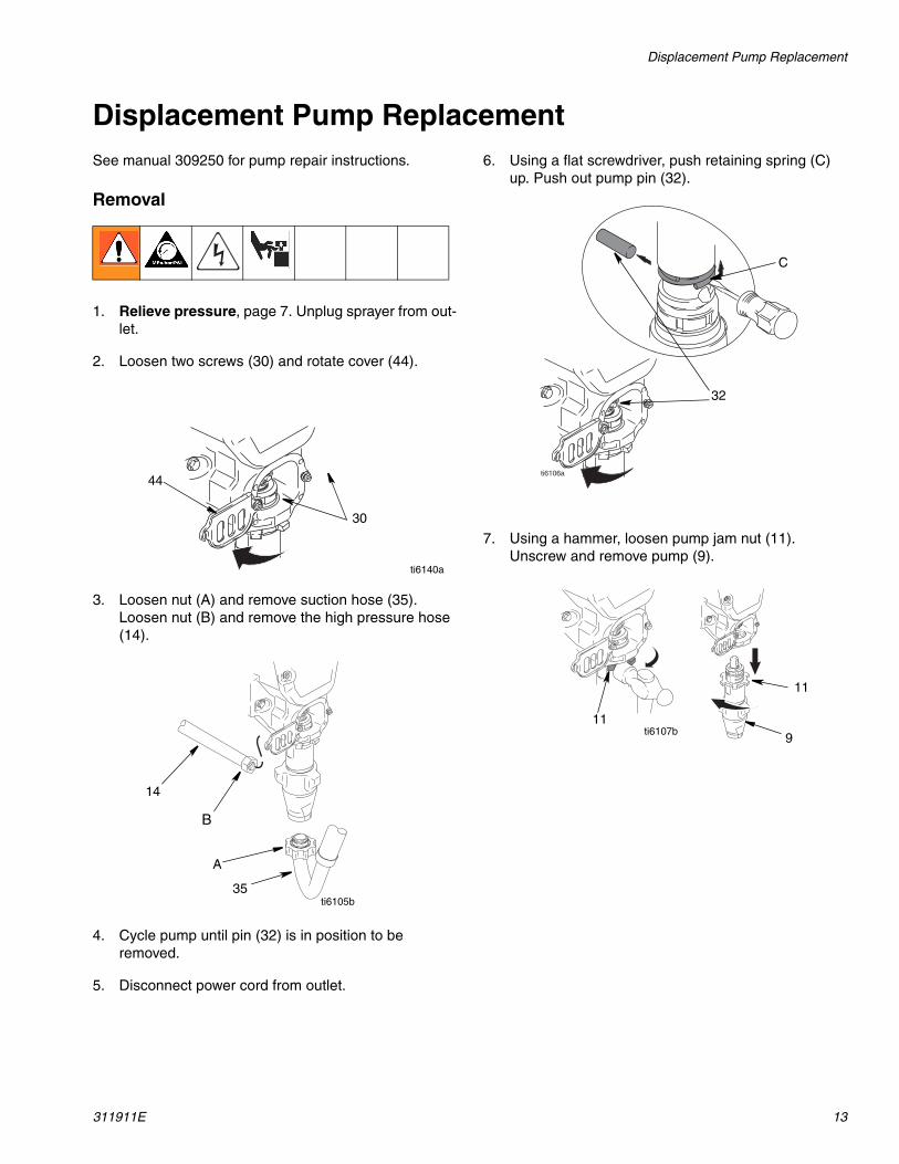
Displacement Pump ReplacementSee manual 309250 for pump repair instructions.
Removal
1. Relieve pressure, page 7. Unplug sprayer from out-let.
2. Loosen two screws (30) and rotate cover (44).
3. Loosen nut (A) and remove suction hose (35). Loosen nut (B) and remove the high pressure hose (14).
4. Cycle pump until pin (32) is in position to be removed.
5. Disconnect power cord from outlet.
6. Using a flat screwdriver, push retaining spring (C) up. Push out pump pin (32).
7. Using a hammer, loosen pump jam nut (11). Unscrew and remove pump (9).
30
44
ti6140a
14
B
A
35ti6105b
C
32
11
11
9ti6107b

Displacement Pump Replacement
14 311911E
Installation
1. Extend pump piston rod full. Apply grease to top of pump rod at (D) or inside connecting rod (7). Install jam nut (11) on pump threads.
2. Install pump rod (D) into connecting rod (7).
3. Install pump pin (32). Verify retainer spring (C) is in groove over pump pin.
4. Push pump (9) up until pump threads engage.
5. Screw in pump until threads are flush with top of drive housing opening.
6. Align pump outlet (E) to back.
7. Screw jam nut (11) up onto pump until nut stops. Tighten jam nut by hand, then tap 1/8 to 1/4 turn with a 20 oz (maximum) hammer to approximately 75 ft-lb (102 N•m).
8. Install suction tube (35) and high pressure hose (14). Tighten nuts (A) and (B).
.
9. Fill packing nut with Graco TSL until fluid flows onto top of seal. Rotate cover (44). Tighten screws (30).
If pump pin works loose, parts could break off due to force of pumping action. Parts could project through air and result in serious injury or property damage.
NOTICEIf the pump jam nut loosens during operation, the threads of the drive housing will be damaged.
7
D
11
ti5732b
7
C
32
9ti6108b
ti6111a
ti
E
11
ti6112c
14
B
A
35 ti6105b
ti5735b

Drive Housing Replacement
311911E 15
Drive Housing Replacement
Removal
1. Relieve pressure, page 7.
2. Remove pump (9). Displacement Pump Replace-ment, page 13.
3. Disconnect power cord from outlet.
4. Remove two screws (30) and cover (32).
5. Remove four screws (6).
6. Pull drive housing (5) out of motor front endbell.
7. Remove gear cluster (2) and (3) and thrust bearing (4) from drive housing.
Installation
1. Apply a liberal coat of grease to gears and needle bearing surfaces. Install thrust bearing (4) and gears (2) and (3) in front endbell housing.
2. Push drive housing into front endbell housing. Insert gear crank (3) through hole in connecting rod (7).
3. Install four screws (6).
4. Install cover (32) with two screws (30).
5. Install pump (9). Displacement Pump Replace-ment, page 13.
NOTICEDo not drop gear cluster (3) and (2) when removing drive housing (5). Gear cluster may stay engaged in motor front endbell or drive housing.
30
326
6
7
5
4
3
2
ti9268a
NeedleBearing Surfaces3
2
4
ti8329b
3
7
ti9267a

Spin Test
16 311911E
Spin TestSee Wiring Diagram, page 36.
To check armature, motor winding and brush electrical continuity:
1. Relieve pressure, page 7. Disconnect power cord from outlet.
2. Remove two screws (30) and shroud (29).
3. Remove drive housing (5), page 15.
4. Disconnect motor connector (F).
Armature Short Circuit Test
Quickly turn motor fan by hand. If motor coasts two or three revolutions before complete stop, there are no electrical shorts. If motor does not spin freely, armature is shorted. Replace motor, page 34.
Armature, Brushes, and Motor Wiring Open Circuit Test (Continuity)
1. Connect red and black motor leads with test lead. Turn motor fan by hand at about two revolutions per second.
2. If uneven or no resistance, check for missing brush caps, broken brush springs, brush leads, and worn brushes. Repair as needed, page 18.
3. If still uneven or no resistance, replace motor, page 34.
4. Reattach motor connector (F).
5. Replace drive housing, page 15.
6. Replace shroud (29) and two screws (30).
29
30
F
F
FinishPro 390 FinishPro 395
ti5638a
ti2572b

Fan Replacement
311911E 17
Fan Replacement
FinishPro 390Removal1. Relieve pressure, page 7. Disconnect power cord
from outlet.
2. Remove two screws (30) and shroud (29).
3. Remove spring clip (1b) on back of motor.
4. Pull off fan (100).
Installation
1. Slide new fan (1a) in place on back of motor. Be sure blades of fan face motor as shown.
2. Install spring clip (1b).
3. Replace shroud (29) and two screws (30).
FinishPro 3951. Relieve pressure, page 7. Disconnect power cord
from outlet.
2. Remove four screws (12) and shroud (23).
3. Remove retaining ring (126) on fan (125).
4. Pull off fan.
Installation
1. Slide new fan (125) on back of motor. Be sure blades of fan face motor as shown.
2. Install retaining ring (126).
3. Replace shroud (23) and four screws (12).
1b
1a
30
29
ti9269a
1223
125126
ti9604a
Motor Brush Replacement
18 311911E
Motor Brush ReplacementSee Wiring Diagram, page 36.
FinishPro 390Removal
Replace brushes worn to less than 1/4 in. (6mm). Brushes wear differently on each side of motor, check both sides. 1. Relieve pressure, page 7. Disconnect power cord
from outlet.
2. Remove two screws (30) and shroud (29) (see illus-tration on page 16).
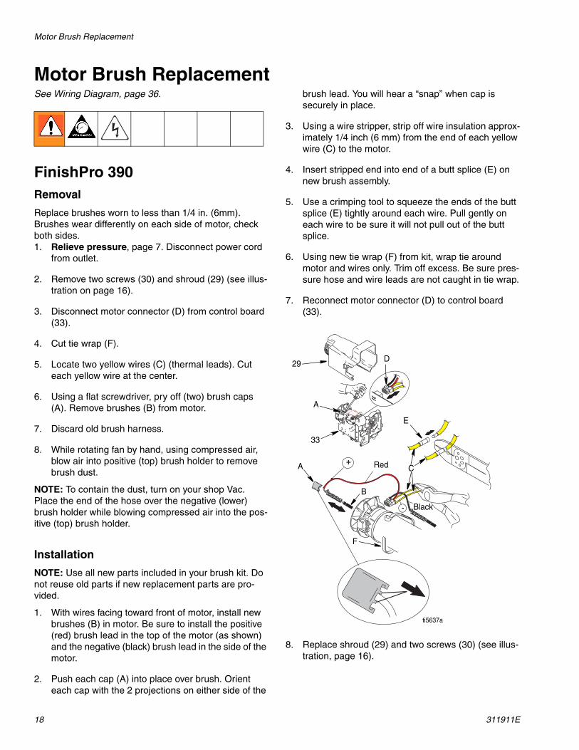
3. Disconnect motor connector (D) from control board (33).
4. Cut tie wrap (F).
5. Locate two yellow wires (C) (thermal leads). Cut each yellow wire at the center.
6. Using a flat screwdriver, pry off (two) brush caps (A). Remove brushes (B) from motor.
7. Discard old brush harness.
8. While rotating fan by hand, using compressed air, blow air into positive (top) brush holder to remove brush dust.
NOTE: To contain the dust, turn on your shop Vac. Place the end of the hose over the negative (lower) brush holder while blowing compressed air into the pos-itive (top) brush holder.
Installation
NOTE: Use all new parts included in your brush kit. Do not reuse old parts if new replacement parts are pro-vided.\1. With wires facing toward front of motor, install new
brushes (B) in motor. Be sure to install the positive (red) brush lead in the top of the motor (as shown) and the negative (black) brush lead in the side of the motor.
2. Push each cap (A) into place over brush. Orient each cap with the 2 projections on either side of the
brush lead. You will hear a “snap” when cap is securely in place.
3. Using a wire stripper, strip off wire insulation approx-imately 1/4 inch (6 mm) from the end of each yellow wire (C) to the motor.
4. Insert stripped end into end of a butt splice (E) on new brush assembly.
5. Use a crimping tool to squeeze the ends of the butt splice (E) tightly around each wire. Pull gently on each wire to be sure it will not pull out of the butt splice.
6. Using new tie wrap (F) from kit, wrap tie around motor and wires only. Trim off excess. Be sure pres-sure hose and wire leads are not caught in tie wrap.
7. Reconnect motor connector (D) to control board (33).
8. Replace shroud (29) and two screws (30) (see illus-tration, page 16).
29
A
33
A
B
Red
Black
F
C
E
D
ti5637a
Motor Brush Replacement
311911E 19
Motor Brush ReplacementFinishPro 395
Removal
Replace brushes worn to less than 1/2 in. Brushes wear differently on each side of motor, check both sides. Brush Repair Kit 287735 is available.
1. Read General Repair Information, page 7.
2. Relieve pressure, page 7.
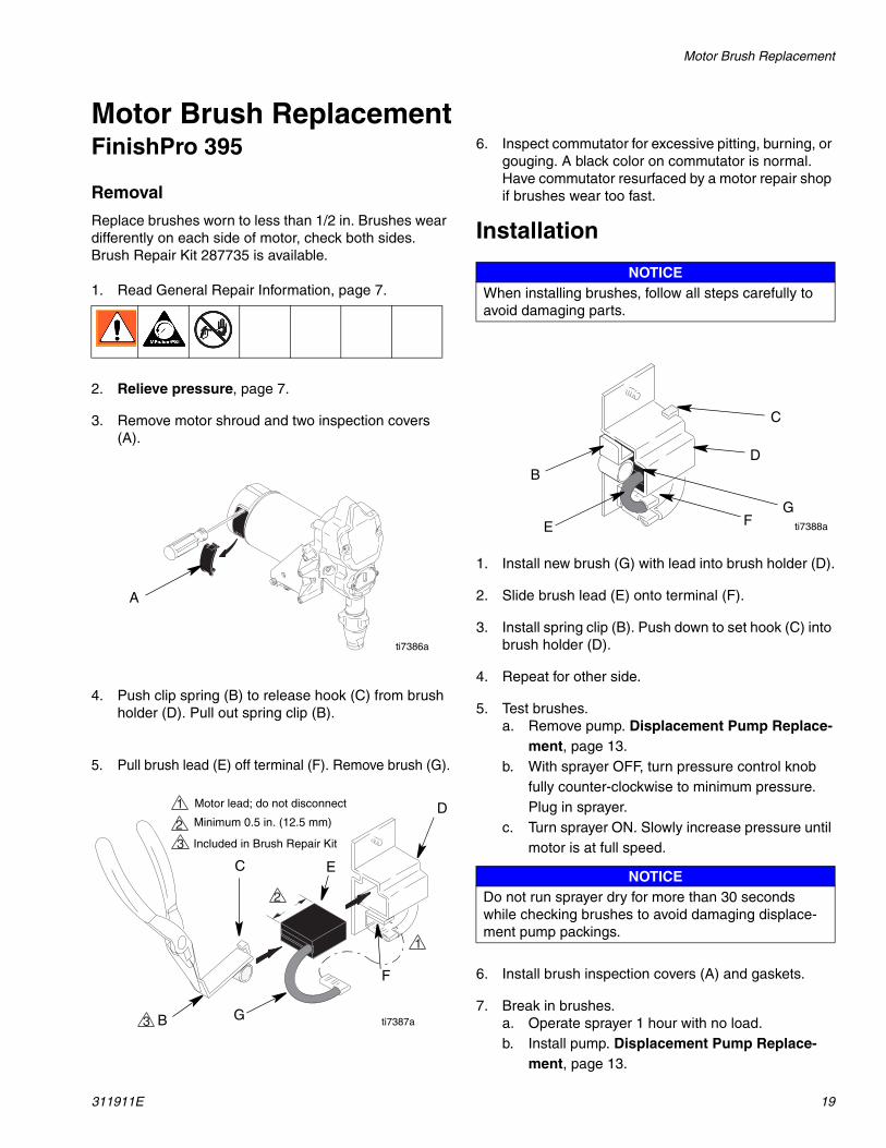
3. Remove motor shroud and two inspection covers (A).
4. Push clip spring (B) to release hook (C) from brush holder (D). Pull out spring clip (B).
5. Pull brush lead (E) off terminal (F). Remove brush (G).
6. Inspect commutator for excessive pitting, burning, or gouging. A black color on commutator is normal. Have commutator resurfaced by a motor repair shop if brushes wear too fast.
Installation
1. Install new brush (G) with lead into brush holder (D).
2. Slide brush lead (E) onto terminal (F).
3. Install spring clip (B). Push down to set hook (C) into brush holder (D).
4. Repeat for other side.
5. Test brushes.a. Remove pump. Displacement Pump Replace-
ment, page 13.b. With sprayer OFF, turn pressure control knob
fully counter-clockwise to minimum pressure. Plug in sprayer.
c. Turn sprayer ON. Slowly increase pressure until motor is at full speed.
6. Install brush inspection covers (A) and gaskets.
7. Break in brushes.a. Operate sprayer 1 hour with no load.b. Install pump. Displacement Pump Replace-
ment, page 13.
A
ti7386a
B
C
G
E
F
D
1
1
2
2
3
3
Motor lead; do not disconnect
Minimum 0.5 in. (12.5 mm)
Included in Brush Repair Kit
ti7387a
NOTICEWhen installing brushes, follow all steps carefully to avoid damaging parts.
NOTICEDo not run sprayer dry for more than 30 seconds while checking brushes to avoid damaging displace-ment pump packings.
B
E
D
C
GF ti7388a
Control Board Replacement
20 311911E
Control Board ReplacementSee Wiring Diagram, page 36.
FinishPro 390Removal
1. Relieve pressure, page 7. Disconnect power cord from outlet.
2. Remove two screws (30) and shroud (29) (see illus-tration, page16).
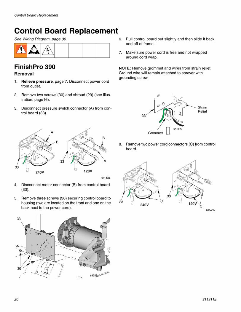
3. Disconnect pressure switch connector (A) from con-trol board (33).
4. Disconnect motor connector (B) from control board (33).
5. Remove three screws (30) securing control board to housing (two are located on the front and one on the back next to the power cord).
6. Pull control board out slightly and then slide it back and off of frame.
7. Make sure power cord is free and not wrapped around cord wrap.
NOTE: Remove grommet and wires from strain relief. Ground wire will remain attached to sprayer with grounding screw..
8. Remove two power cord connectors (C) from control board.
120V240Vti6143b
33
33
A
BB
A
30
33
ti9258a
ti6122a
33
Grommet
StrainRelief
120V240V
ti6143b
33
33
CC

Control Board Replacement
311911E 21
Installation
1. Position grommet and power cord wires through strain relief in control board (33).
2. Connect the power cord connectors to the correct terminals indicated on the control board (120V, black and white, 240V, blue and brown) on control board (33).
3. Carefully slide control board back into place on the side of the motor frame.
4. Install three screws (30). Torque to 30-35 in-lb (3.4-3.9 N.m).
5. Attach motor connector (B) and pressure control assembly connector (A).
6. Install shroud (29) and two screws (30) (see illustra-tion, page 16).
ti6122a
33
Grommet
StrainRelief
120V240Vti6143b
3333
CC
30
33
ti9258a
120V240V
ti6143b
33 33
A
BB
A
Control Board Replacement
22 311911E
FinishPro 395See Wiring Diagram, page 36.
Removal
1. Relieve pressure, page 7. Disconnect power cord from outlet.
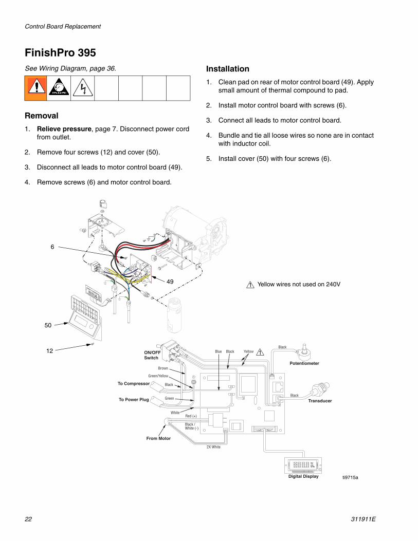
2. Remove four screws (12) and cover (50).
3. Disconnect all leads to motor control board (49).
4. Remove screws (6) and motor control board.
Installation
1. Clean pad on rear of motor control board (49). Apply small amount of thermal compound to pad.
2. Install motor control board with screws (6).
3. Connect all leads to motor control board.
4. Bundle and tie all loose wires so none are in contact with inductor coil.
5. Install cover (50) with four screws (6).
To Compressor
Yellow
White
Black
Green
Brown
Green/Yellow
Black
Black
To Power Plug
From Motor
ON/OFFSwitch
Digital Display
Transducer
Potentiometer
BlackBlue
2X White
Red (+)
Black /White (-)
50
12
6
49
ti9715a
1
1 Yellow wires not used on 240V
On/Off Switch Replacement
311911E 23
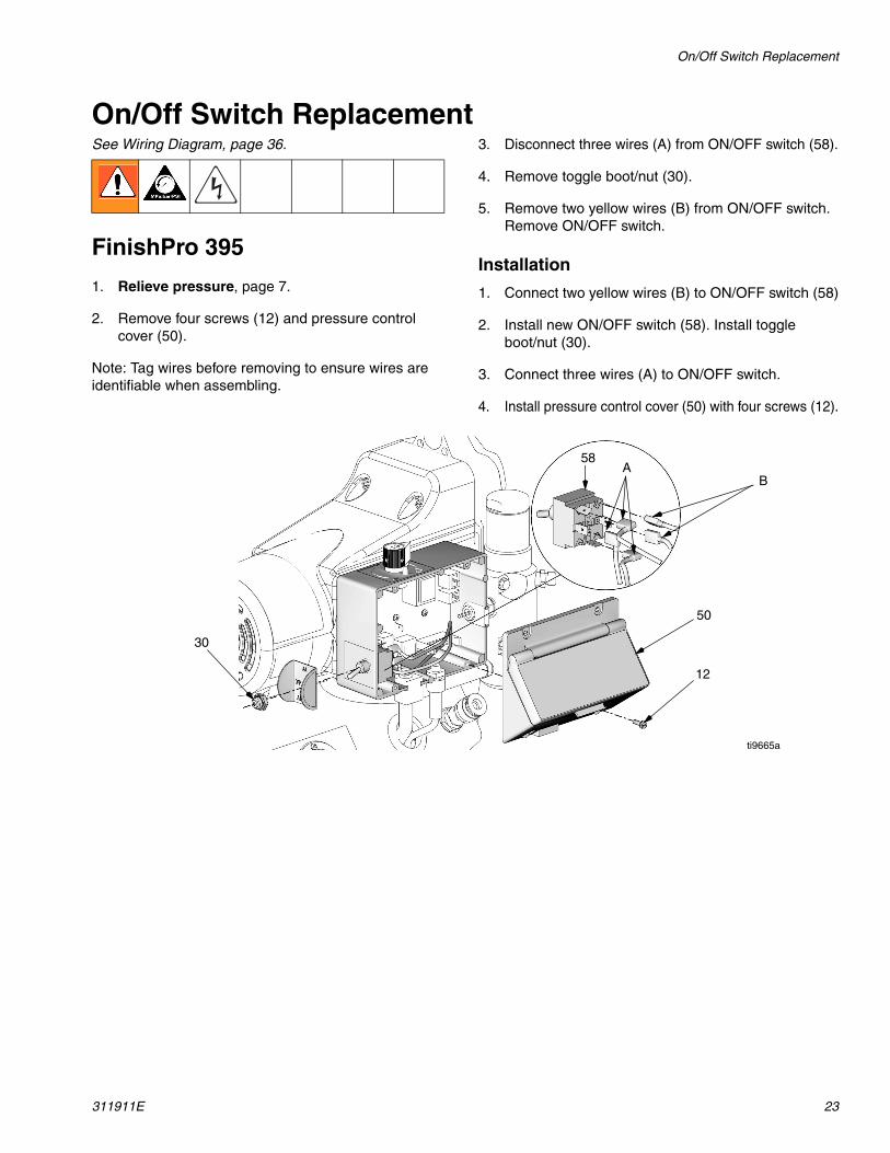
On/Off Switch ReplacementSee Wiring Diagram, page 36.
FinishPro 395
1. Relieve pressure, page 7.
2. Remove four screws (12) and pressure control cover (50).
Note: Tag wires before removing to ensure wires are identifiable when assembling.
3. Disconnect three wires (A) from ON/OFF switch (58).
4. Remove toggle boot/nut (30).
5. Remove two yellow wires (B) from ON/OFF switch. Remove ON/OFF switch.
Installation
1. Connect two yellow wires (B) to ON/OFF switch (58)
2. Install new ON/OFF switch (58). Install toggle boot/nut (30).
3. Connect three wires (A) to ON/OFF switch.
4. Install pressure control cover (50) with four screws (12).
30
50
12
AB
58
ti9665a

On/Off Switch Replacement
24 311911E
FinishPro 390Removal
1. Relieve pressure, page 7.
2. Remove four screws (12) and switch box cover (50).
NOTE: Tag wires before removing to ensure wires are identifiable when assembling.
3. Disconnect three wires (A) from ON/OFF switch (58).
4. Remove toggle boot/nut (30). Remove ON/OFF switch (58).
Installation
1. Install new ON/OFF switch (58). Install toggle boot/nut (30).
2. Connect three wires (A) to ON/OFF switch (58).
3. Install switch box cover (50) with four screws (12).
A
58
50
12
30
ti9649a
Fuse Replacement
311911E 25
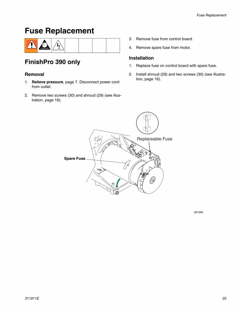
Fuse Replacement
FinishPro 390 only
Removal
1. Relieve pressure, page 7. Disconnect power cord from outlet.
2. Remove two screws (30) and shroud (29) (see illus-tration, page 16).
3. Remove fuse from control board.
4. Remove spare fuse from motor.
Installation
1. Replace fuse on control board with spare fuse.
2. Install shroud (29) and two screws (30) (see illustra-tion, page 16).
Replaceable Fuse
ti6174b
ti9134b
Spare Fuse
Removing and Installing Air Filter
26 311911E
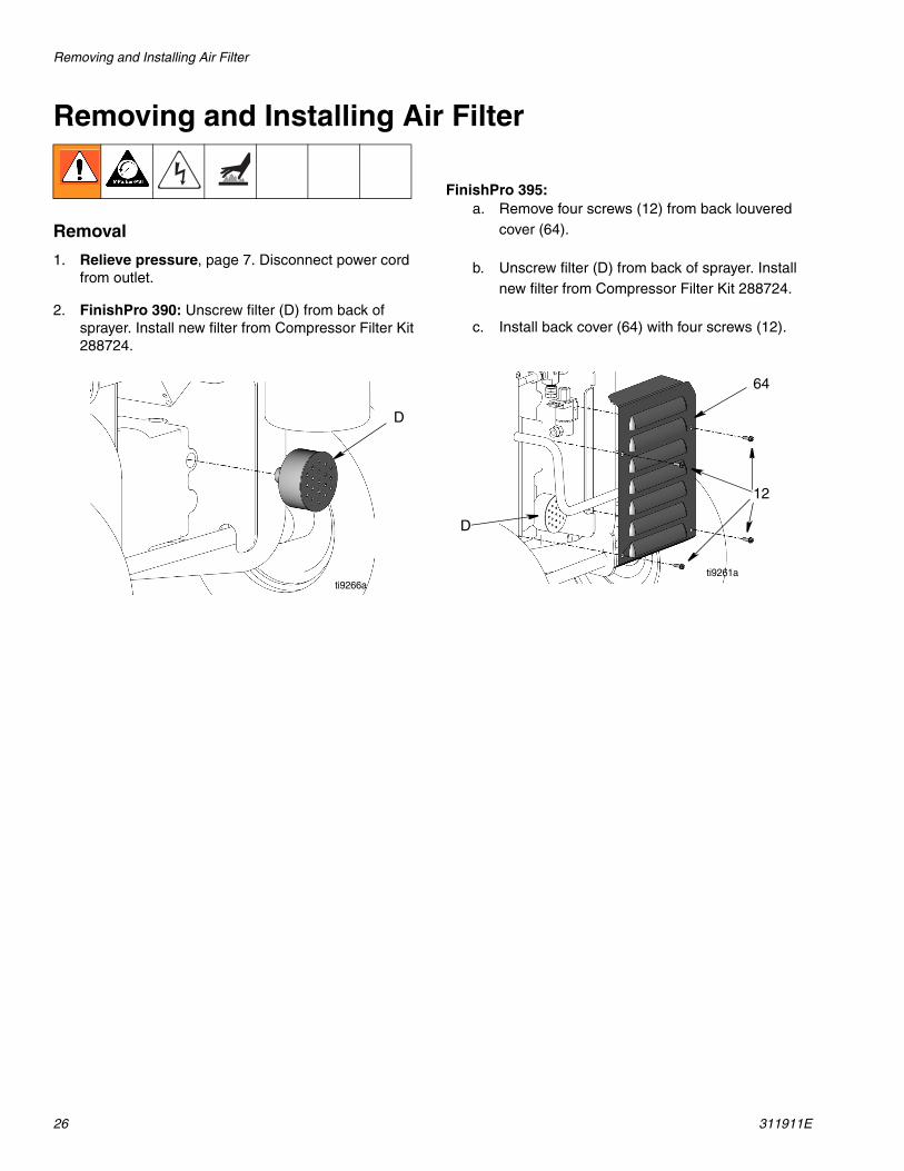
Removing and Installing Air Filter
Removal
1. Relieve pressure, page 7. Disconnect power cord from outlet.
2. FinishPro 390: Unscrew filter (D) from back of sprayer. Install new filter from Compressor Filter Kit 288724.
FinishPro 395: a. Remove four screws (12) from back louvered
cover (64).
b. Unscrew filter (D) from back of sprayer. Install new filter from Compressor Filter Kit 288724.
c. Install back cover (64) with four screws (12).
D
ti9266a
12
64
D
ti9261a

Compressor Replacement and Repair
311911E 27
Compressor Replacement and Repair
To repair compressor, use Compressor Service Kit 288723. Refer to Thomas Compressor manual pro-vided. To replace compressor piston assembly, use Kit 288723.
Removing Compressor from Sprayer
1. Relieve pressure, page 7. Disconnect power cord from outlet.
2. Remove front and back louvers from sprayer.
3. Remove toolbox from the sprayer.
4. Unscrew the compression fittings from the front and rear of the sprayer.
5. Remove tubing.
6. Disconnect electrical connection from solenoid valve at the rear of the sprayer.
7. Remove muffler from the back of the compressor.
8. Remove the four screws from the sprayer that are located underneath the removed toolbox.
NOTE: Remove bottom screws first. When you have one screw left to remove, hold onto the compressor so it doesn’t fall out the bottom.
9. Remove compressor from sprayer.
10. Disconnect electrical connection.NOTICE
To prevent damage to the tubing the compression fit-tings must be removed first.
Front Louvers Back Louversti9259a ti9261a
ti9262a
ti9265a
ti9263a
Pressure Control Replacement: FinishPro 390
28 311911E
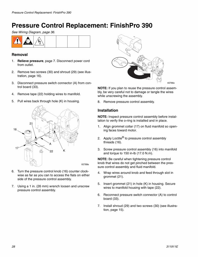
Pressure Control Replacement: FinishPro 390See Wiring Diagram, page 36.
Removal
1. Relieve pressure, page 7. Disconnect power cord from outlet.
2. Remove two screws (30) and shroud (29) (see illus-tration, page 16).
3. Disconnect pressure switch connector (A) from con-trol board (33).
4. Remove tape (22) holding wires to manifold.
5. Pull wires back through hole (K) in housing.
6. Turn the pressure control knob (16) counter clock-wise as far as you can to access the flats on either side of the pressure control assembly.
7. Using a 1 in. (26 mm) wrench loosen and unscrew pressure control assembly.
NOTE: If you plan to reuse the pressure control assem-bly, be very careful not to damage or tangle the wires while unscrewing the assembly.
8. Remove pressure control assembly.
Installation
NOTE: Inspect pressure control assembly before instal-lation to verify the o-ring is installed and in place.
1. Align grommet collar (17) on fluid manifold so open-ing faces toward motor.
2. Apply Loctite® to pressure control assemblythreads (16).
3. Screw pressure control assembly (16) into manifold and torque to 150 in-lb (17.0 N.m).
NOTE: Be careful when tightening pressure control knob that wires do not get pinched between the pres-sure control assembly and fluid manifold.
4. Wrap wires around knob and feed through slot in grommet (21).
5. Insert grommet (21) in hole (K) in housing. Secure wires to manifold housing with tape (22).
6. Reconnect pressure switch connector (A) to control board (33).
7. Install shroud (29) and two screws (30) (see illustra-tion, page 15).
16
17
21
22
A
K
ti5768e
ti5766c
Pressure Control Replacement: FinishPro 390
311911E 29
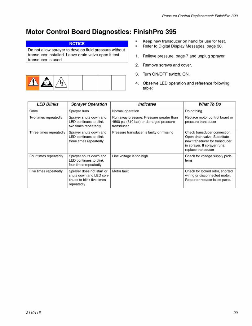
Motor Control Board Diagnostics: FinishPro 395• Keep new transducer on hand for use for test.• Refer to Digital Display Messages, page 30.
1. Relieve pressure, page 7 and unplug sprayer.
2. Remove screws and cover.
3. Turn ON/OFF switch, ON.
4. Observe LED operation and reference following table:
NOTICE
Do not allow sprayer to develop fluid pressure without transducer installed. Leave drain valve open if test transducer is used.
LED Blinks Sprayer Operation Indicates What To Do
Once Sprayer runs Normal operation Do nothing
Two times repeatedly Sprayer shuts down and LED continues to blink two times repeatedly
Run away pressure. Pressure greater than 4500 psi (310 bar) or damaged pressure transducer
Replace motor control board or pressure transducer
Three times repeatedly Sprayer shuts down and LED continues to blink three times repeatedly
Pressure transducer is faulty or missing Check transducer connection. Open drain valve. Substitute new transducer for transducer in sprayer. If sprayer runs, replace transducer
Four times repeatedly Sprayer shuts down and LED continues to blink four times repeatedly
Line voltage is too high Check for voltage supply prob-lems
Five times repeatedly Sprayer does not start or shuts down and LED con-tinues to blink five times repeatedly
Motor fault Check for locked rotor, shorted wiring or disconnected motor. Repair or replace failed parts.

Pressure Control Replacement: FinishPro 390
30 311911E
Digital Display Messages: FinishPro 395• No display does not mean the sprayer is not
pressurized. Relieve pressure before repair.
Pressure Control Transducer:FinishPro 395
Removal
1. Relieve pressure, page 7. Unplug sprayer.
2. Remove screws and cover.
3. Disconnect lead (E) from motor control board.
4. Remove two screws and filter housing.
5. Thread transducer lead plastic connector down through transducer grommet.
6. Remove pressure control transducer and packing o-ring from filter housing.
Installation
1. Install packing o-ring and pressure control trans-ducer in filter housing. Torque to 30-35 ft-lb.
2. Thread transducer lead plastic connector up through transducer grommet.
3. Install filter housing with two screws.
4. Connect lead to motor control board.
5. Install cover with screws.
Display Sprayer Operation Indicates What To Do
No Display Sprayer stops. Power is not applied. Sprayer may be pressurized.
Loss of power. Check power source. Relieve pressure before repair or disas-sembly.
3000 psi210 bar21 MPa
Sprayer is pressurized. Power is applied. (Pressure varies with tip size and pressure control setting.)
Normal operation. Spray.
E=02 Sprayer may continue to run. Power is applied.
Pressure greater than 4500p psi (310 bar, 31 mpa) or a pressure trans-ducer is faulty.
Replace pressure control board or pressure transducer.
E=03 Sprayer stops. Power is applied. Pressure transducer faulty, bad connection or broken wire.
Check transducer connection. Open drain valve. Substitute new transducer for transducer in sprayer. If sprayer runs, replace transducer.
E=04 Sprayer stops. Power is applied. Line voltage too high. Check for voltage supply prob-lem.
E=05 Sprayer does not start or stops. Power is applied.
Motor fault. Check for locked rotor, shorted wiring or disconnected motor. Repair or replace failed parts.
- - - - Power is applied. Pressure is less than 200 psi (14 bar, 1.4 MPa)
Increase pressure if desired. Drain valve may be open.
EMPTY Sprayer stops. Power is applied. Empty paint pail. Loss of pressure.
Refill paint pail. Check for leaks or clogged pump inlet. Repeat Startup procedure.
Pressure Control Replacement: FinishPro 390
311911E 31
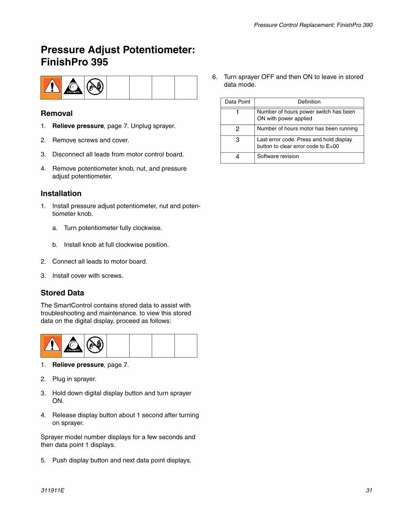
Pressure Adjust Potentiometer: FinishPro 395
Removal
1. Relieve pressure, page 7. Unplug sprayer.
2. Remove screws and cover.
3. Disconnect all leads from motor control board.
4. Remove potentiometer knob, nut, and pressure adjust potentiometer.
Installation
1. Install pressure adjust potentiometer, nut and poten-tiometer knob.
a. Turn potentiometer fully clockwise.
b. Install knob at full clockwise position.
2. Connect all leads to motor board.
3. Install cover with screws.
Stored Data
The SmartControl contains stored data to assist with troubleshooting and maintenance. to view this stored data on the digital display, proceed as follows:
1. Relieve pressure, page 7.
2. Plug in sprayer.
3. Hold down digital display button and turn sprayer ON.
4. Release display button about 1 second after turning on sprayer.
Sprayer model number displays for a few seconds and then data point 1 displays.
5. Push display button and next data point displays.
6. Turn sprayer OFF and then ON to leave in stored data mode.
Data Point Definition
1 Number of hours power switch has been ON with power applied
2 Number of hours motor has been running
3 Last error code. Press and hold display button to clear error code to E=00
4 Software revision
Drain Valve Replacement
32 311911E
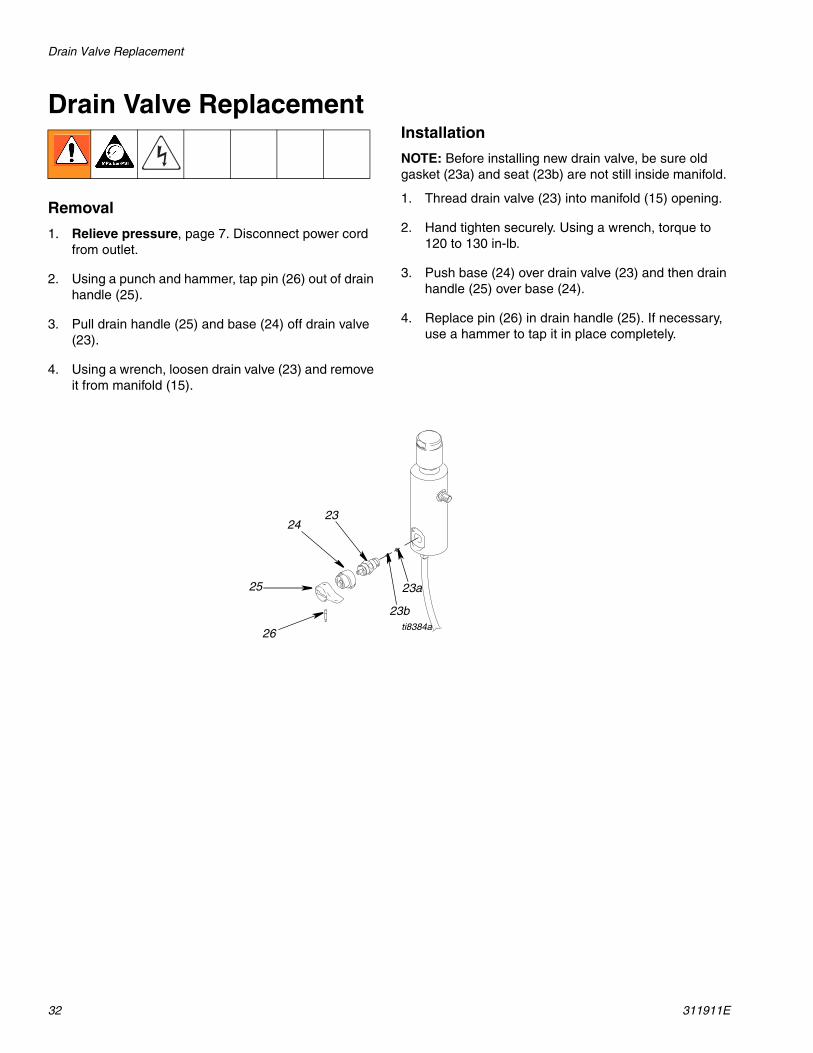
Drain Valve Replacement
Removal
1. Relieve pressure, page 7. Disconnect power cord from outlet.
2. Using a punch and hammer, tap pin (26) out of drain handle (25).
3. Pull drain handle (25) and base (24) off drain valve (23).
4. Using a wrench, loosen drain valve (23) and remove it from manifold (15).
Installation
NOTE: Before installing new drain valve, be sure old gasket (23a) and seat (23b) are not still inside manifold.
1. Thread drain valve (23) into manifold (15) opening.
2. Hand tighten securely. Using a wrench, torque to 120 to 130 in-lb.
3. Push base (24) over drain valve (23) and then drain handle (25) over base (24).
4. Replace pin (26) in drain handle (25). If necessary, use a hammer to tap it in place completely.
23a
23b
2324
25
26ti8384a

Drain Line Removal/Replacement
311911E 33
Drain Line Removal/Replacement
FinishPro 390Removal
To remove the drain line (40) from the manifold:
1. Cut drain line (40) from barbed fitting (20).
2. Unscrew barbed fitting (20) from manifold.
NOTE: If you replace the manifold and reuse the exist-ing barbed fitting (20) and drain line (40), cut the remain-ing drain line material off the end of the barbed fitting (20) with a sharp knife.
Installation
1. Screw barbed fitting (20) into manifold.
2. Push drain line (40) onto barbed fitting (20).
NOTE: To make the drain line more pliable and easier to install on barbed fitting, heat drain line (40) end with a hair dryer or place end in hot water a few seconds.
FinishPro 395Removal: Unscrew drain line (55) from filter manifold (15).
Installation: Screw drain line (55) into filter manifold (15).
20
40
ti8333a
FinishPro 390 FinishPro 395
55 15 ti9603a
Motor Replacement
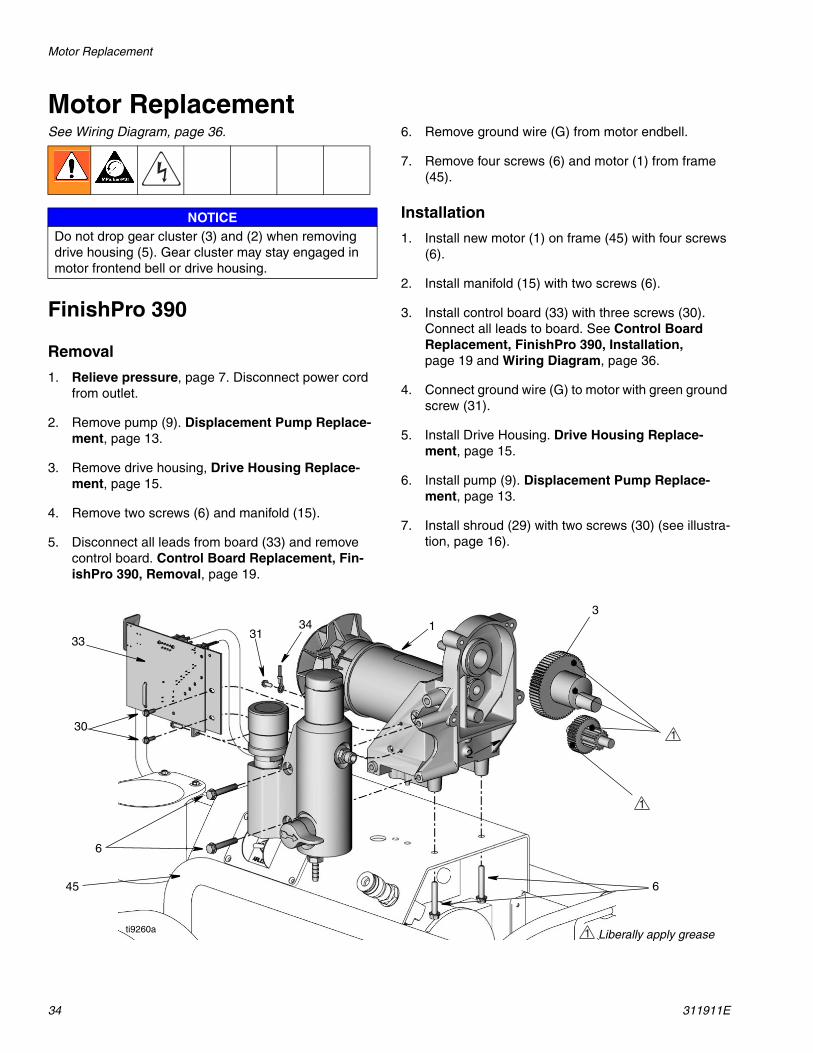
34 311911E
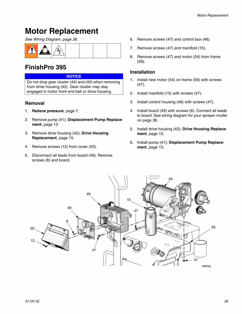
Motor ReplacementSee Wiring Diagram, page 36.
FinishPro 390
Removal
1. Relieve pressure, page 7. Disconnect power cord from outlet.
2. Remove pump (9). Displacement Pump Replace-ment, page 13.
3. Remove drive housing, Drive Housing Replace-ment, page 15.
4. Remove two screws (6) and manifold (15).
5. Disconnect all leads from board (33) and remove control board. Control Board Replacement, Fin-ishPro 390, Removal, page 19.
6. Remove ground wire (G) from motor endbell.
7. Remove four screws (6) and motor (1) from frame (45).
Installation
1. Install new motor (1) on frame (45) with four screws (6).
2. Install manifold (15) with two screws (6).
3. Install control board (33) with three screws (30). Connect all leads to board. See Control Board Replacement, FinishPro 390, Installation, page 19 and Wiring Diagram, page 36.
4. Connect ground wire (G) to motor with green ground screw (31).
5. Install Drive Housing. Drive Housing Replace-ment, page 15.
6. Install pump (9). Displacement Pump Replace-ment, page 13.
7. Install shroud (29) with two screws (30) (see illustra-tion, page 16).
NOTICEDo not drop gear cluster (3) and (2) when removing drive housing (5). Gear cluster may stay engaged in motor frontend bell or drive housing.
3133
30
6
13
2
645
34
1
1 Liberally apply grease
1
ti9260a
Motor Replacement
311911E 35
Motor ReplacementSee Wiring Diagram, page 36.
FinishPro 395
Removal
1. Relieve pressure, page 7.
2. Remove pump (41); Displacement Pump Replace-ment, page 13
3. Remove drive housing (42); Drive Housing Replacement, page 15.
4. Remove screws (12) from cover (50).
5. Disconnect all leads from board (49). Remove screws (6) and board.
6. Remove screws (47) and control box (48).
7. Remove screws (47) and manifold (15).
8. Remove screws (47) and motor (54) from frame (59).
Installation
1. Install new motor (54) on frame (59) with screws (47).
2. Install manifold (15) with screws (47).
3. Install control housing (48) with screws (47).
4. Install board (49) with screws (6). Connect all leads to board. See wiring diagram for your sprayer model on page 36.
5. Install drive housing (42); Drive Housing Replace-ment, page 15.
6. Install pump (41); Displacement Pump Replace-ment, page 13.
NOTICEDo not drop gear cluster (44) and (40) when removing from drive housing (42). Gear cluster may stay engaged in motor front end bell or drive housing.
48
12
50
49
6
47
15
47
47
54
59
ti9605a
Wiring Diagram
36 311911E
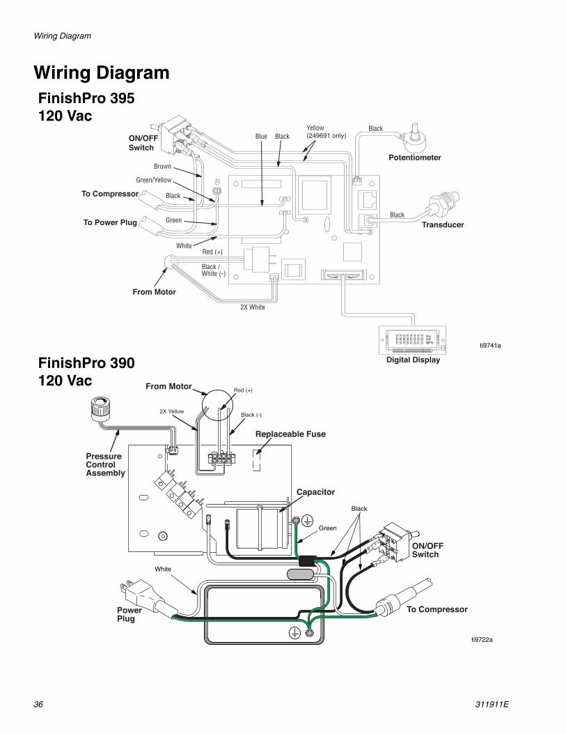
Wiring DiagramFinishPro 395
ti9741a
ti9722a
Capacitor
To Compressor
ON/OFFSwitch
PowerPlug
PressureControlAssembly
From Motor
Replaceable Fuse
Black (-)
Red (+)
2X Yellow
FinishPro 390
Green
White
Black
120 Vac
120 Vac

Wiring Diagram
311911E 37
To Compressor
ON/OFFSwitch
PowerPlug
Capacitor
Pressure ControlAssemblyFrom Motor
Replaceable Fuse
Black (-)
Red (+)
2X Yellow
FinishPro 390240 Vac

Wiring Diagram
38 311911E
Notes
Technical Data
311911E 39
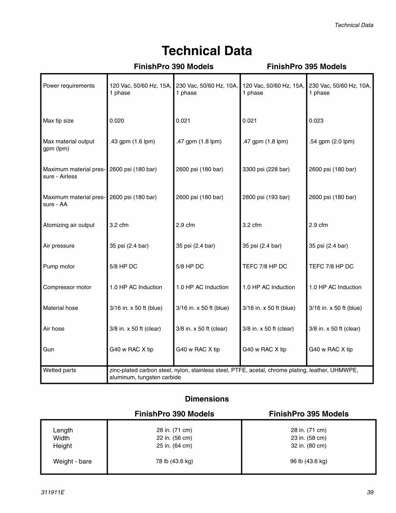
Technical Data
Dimensions
FinishPro 390 Models FinishPro 395 Models
Power requirements 120 Vac, 50/60 Hz, 15A, 1 phase
230 Vac, 50/60 Hz, 10A, 1 phase
120 Vac, 50/60 Hz, 15A, 1 phase
230 Vac, 50/60 Hz, 10A, 1 phase
Max tip size 0.020 0.021 0.021 0.023
Max material output gpm (lpm)
.43 gpm (1.6 lpm) .47 gpm (1.8 lpm) .47 gpm (1.8 lpm) .54 gpm (2.0 lpm)
Maximum material pres-sure - Airless
2600 psi (180 bar) 2600 psi (180 bar) 3300 psi (228 bar) 2600 psi (180 bar)
Maximum material pres-sure - AA
2600 psi (180 bar) 2600 psi (180 bar) 2800 psi (193 bar) 2600 psi (180 bar)
Atomizing air output 3.2 cfm 2.9 cfm 3.2 cfm 2.9 cfm
Air pressure 35 psi (2.4 bar) 35 psi (2.4 bar) 35 psi (2.4 bar) 35 psi (2.4 bar)
Pump motor 5/8 HP DC 5/8 HP DC TEFC 7/8 HP DC TEFC 7/8 HP DC
Compressor motor 1.0 HP AC Induction 1.0 HP AC Induction 1.0 HP AC Induction 1.0 HP AC Induction
Material hose 3/16 in. x 50 ft (blue) 3/16 in. x 50 ft (blue) 3/16 in. x 50 ft (blue) 3/16 in. x 50 ft (blue)
Air hose 3/8 in. x 50 ft (clear) 3/8 in. x 50 ft (clear) 3/8 in. x 50 ft (clear) 3/8 in. x 50 ft (clear)
Gun G40 w RAC X tip G40 w RAC X tip G40 w RAC X tip G40 w RAC X tip
Wetted parts zinc-plated carbon steel, nylon, stainless steel, PTFE, acetal, chrome plating, leather, UHMWPE, aluminum, tungsten carbide
FinishPro 390 Models FinishPro 395 Models
Length 28 in. (71 cm) 28 in. (71 cm)Width 22 in. (56 cm) 23 in. (58 cm)Height 25 in. (64 cm) 32 in. (80 cm)
Weight - bare 78 lb (43.6 kg) 96 lb (43.6 kg)

All written and visual data contained in this document reflects the latest product information available at the time of publication. Graco reserves the right to make changes at any time without notice.
Original instructions. This manual contains English. MM 311911
Graco Headquarters: MinneapolisInternational Offices: Belgium, China, Japan, Korea
GRACO INC. AND SUBSIDIARIES • P.O. BOX 1441 • MINNEAPOLIS MN 55440-1441 • USA
Copyright 2007, Graco Inc. All Graco manufacturing locations are registered to ISO 9001.www.graco.comRevised 01/2012
Graco Standard WarrantyGraco warrants all equipment referenced in this document which is manufactured by Graco and bearing its name to be free from defects in material and workmanship on the date of sale to the original purchaser for use. With the exception of any special, extended, or limited warranty published by Graco, Graco will, for a period of twelve months from the date of sale, repair or replace any part of the equipment determined by Graco to be defective. This warranty applies only when the equipment is installed, operated and maintained in accordance with Graco’s written recommendations.
This warranty does not cover, and Graco shall not be liable for general wear and tear, or any malfunction, damage or wear caused by faulty installation, misapplication, abrasion, corrosion, inadequate or improper maintenance, negligence, accident, tampering, or substitution of non-Graco component parts. Nor shall Graco be liable for malfunction, damage or wear caused by the incompatibility of Graco equipment with structures, accessories, equipment or materials not supplied by Graco, or the improper design, manufacture, installation, operation or maintenance of structures, accessories, equipment or materials not supplied by Graco.
This warranty is conditioned upon the prepaid return of the equipment claimed to be defective to an authorized Graco distributor for verification of the claimed defect. If the claimed defect is verified, Graco will repair or replace free of charge any defective parts. The equipment will be returned to the original purchaser transportation prepaid. If inspection of the equipment does not disclose any defect in material or workmanship, repairs will be made at a reasonable charge, which charges may include the costs of parts, labor, and transportation.
THIS WARRANTY IS EXCLUSIVE, AND IS IN LIEU OF ANY OTHER WARRANTIES, EXPRESS OR IMPLIED, INCLUDING BUT NOT LIMITED TO WARRANTY OF MERCHANTABILITY OR WARRANTY OF FITNESS FOR A PARTICULAR PURPOSE.
Graco’s sole obligation and buyer’s sole remedy for any breach of warranty shall be as set forth above. The buyer agrees that no other remedy (including, but not limited to, incidental or consequential damages for lost profits, lost sales, injury to person or property, or any other incidental or consequential loss) shall be available. Any action for breach of warranty must be brought within two (2) years of the date of sale.
GRACO MAKES NO WARRANTY, AND DISCLAIMS ALL IMPLIED WARRANTIES OF MERCHANTABILITY AND FITNESS FOR A PARTICULAR PURPOSE, IN CONNECTION WITH ACCESSORIES, EQUIPMENT, MATERIALS OR COMPONENTS SOLD BUT NOT MANUFACTURED BY GRACO. These items sold, but not manufactured by Graco (such as electric motors, switches, hose, etc.), are subject to the warranty, if any, of their manufacturer. Graco will provide purchaser with reasonable assistance in making any claim for breach of these warranties.
In no event will Graco be liable for indirect, incidental, special or consequential damages resulting from Graco supplying equipment hereunder, or the furnishing, performance, or use of any products or other goods sold hereto, whether due to a breach of contract, breach of warranty, the negligence of Graco, or otherwise.
FOR GRACO CANADA CUSTOMERSThe Parties acknowledge that they have required that the present document, as well as all documents, notices and legal proceedings entered into, given or instituted pursuant hereto or relating directly or indirectly hereto, be drawn up in English. Les parties reconnaissent avoir convenu que la rédaction du présente document sera en Anglais, ainsi que tous documents, avis et procédures judiciaires exécutés, donnés ou intentés, à la suite de ou en rapport, directement ou indirectement, avec les procédures concernées.
Graco InformationFor the latest information about Graco products, visit www.graco.com.
TO PLACE AN ORDER, contact your Graco distributor or call 1-800-690-2894 to identify the nearest distributor.


