
FPGA Based Digital SignalProcessing – Applications &Techniques
FPGA Based Digital SignalProcessing – Applications &Techniques
Nathan EddyFermilabBIW12 Tutorial

Outline
Digital Signal Processing Basics
Modern FPGA Overview
Instrumentation Examples
FermilabBIW 12 Nathan Eddy
Digital Signal Processing Basics
Modern FPGA Overview
Instrumentation Examples
Advantages of Digital SignalProcessing (DSP) NO DRIFT – due to temperature or age ACCURACY – defined by number of bits PREDICTABILITY – from simulation PERFORMANCE Linear Phase Response possible Adaptability in terms of resources
PRODUCTION – identical units, no tuning FLEXIBILITY – via firmware modifications DYNAMIC RANGE
FermilabBIW 12
NO DRIFT – due to temperature or age ACCURACY – defined by number of bits PREDICTABILITY – from simulation PERFORMANCE Linear Phase Response possible Adaptability in terms of resources
PRODUCTION – identical units, no tuning FLEXIBILITY – via firmware modifications DYNAMIC RANGE
Nathan Eddy
For Beam Instrumentation Need to work with analog input signals Beam pickups, Schottky detectors, Torroids,
etc Requires Analog to Digital Converters (ADCs)
Need to produce analog output signals To act on the beam – RF, kick signals, etc Require Digital to Analog Converters (DACs)
The effectiveness of FPGA solutions is largelydominated by the performance of the converters
FermilabBIW 12
Need to work with analog input signals Beam pickups, Schottky detectors, Torroids,
etc Requires Analog to Digital Converters (ADCs)
Need to produce analog output signals To act on the beam – RF, kick signals, etc Require Digital to Analog Converters (DACs)
The effectiveness of FPGA solutions is largelydominated by the performance of the converters
Nathan Eddy
Practical Limitations of Sampling
Common sources of sampling error Aliasing Quantization Sample Clock Jitter
Can be characterized by their impact on theSignal to Noise Ratio (SNR) of the sampledsignal SNR ~ log(Sa/Na) Typically expressed in decibels (db)
FermilabBIW 12
Common sources of sampling error Aliasing Quantization Sample Clock Jitter
Can be characterized by their impact on theSignal to Noise Ratio (SNR) of the sampledsignal SNR ~ log(Sa/Na) Typically expressed in decibels (db)
Nathan Eddy
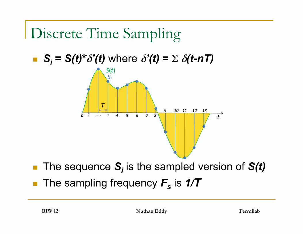
Discrete Time Sampling Si = S(t)* ’(t) where ’(t) = (t-nT)
The sequence Si is the sampled version of S(t) The sampling frequency Fs is 1/T
FermilabBIW 12
Si = S(t)* ’(t) where ’(t) = (t-nT)
The sequence Si is the sampled version of S(t) The sampling frequency Fs is 1/T
Nathan Eddy

Sampling Theorem For ideal reconstruction Fs > 2B where B is
the highest frequency in the signal of interest
Sampling ambiguity
FermilabBIW 12
For ideal reconstruction Fs > 2B where B isthe highest frequency in the signal of interest
Sampling ambiguity
Nathan Eddy

Aliasing Signals at frequencies larger Fs/2 than will
“alias” into the first Nyquist band
Undersampling makes use of this effect
FermilabBIW 12
Signals at frequencies larger Fs/2 than will“alias” into the first Nyquist band
Undersampling makes use of this effect
Nathan Eddy

Quantization Results in signal noise
SNRdb = 1.76 + 6.02N, N=number of bits
FermilabBIW 12
Results in signal noise
SNRdb = 1.76 + 6.02N, N=number of bits
Nathan Eddy

Oversampling Improves SNR
Gain SNRdb = 10log(R) where R=Fs/2B Fs is the sampling Frequency B is signal bandwidth
Also relaxes the requirements on the anti-aliasing analog filter
FermilabBIW 12
Gain SNRdb = 10log(R) where R=Fs/2B Fs is the sampling Frequency B is signal bandwidth
Also relaxes the requirements on the anti-aliasing analog filter
Nathan Eddy

Another source of signal noise Proportional to maximum signal frequency, fmax
RMS sampling clock jitter, Ta
SNRdb = 20log(1/(2 fmaxTa)) A significant effect for undersampling
applications
Sampling Clock Jitter
FermilabBIW 12
Another source of signal noise Proportional to maximum signal frequency, fmax
RMS sampling clock jitter, Ta
SNRdb = 20log(1/(2 fmaxTa)) A significant effect for undersampling
applications
Nathan Eddy
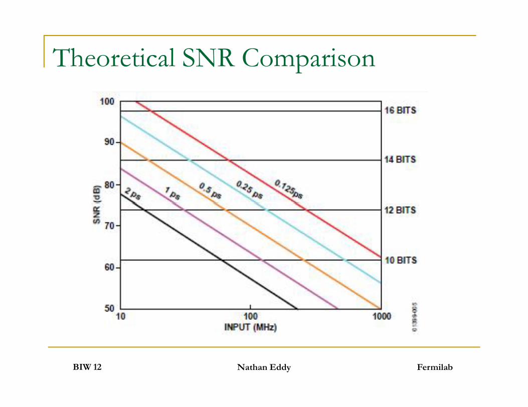
Theoretical SNR Comparison
FermilabBIW 12 Nathan Eddy
The Z domain
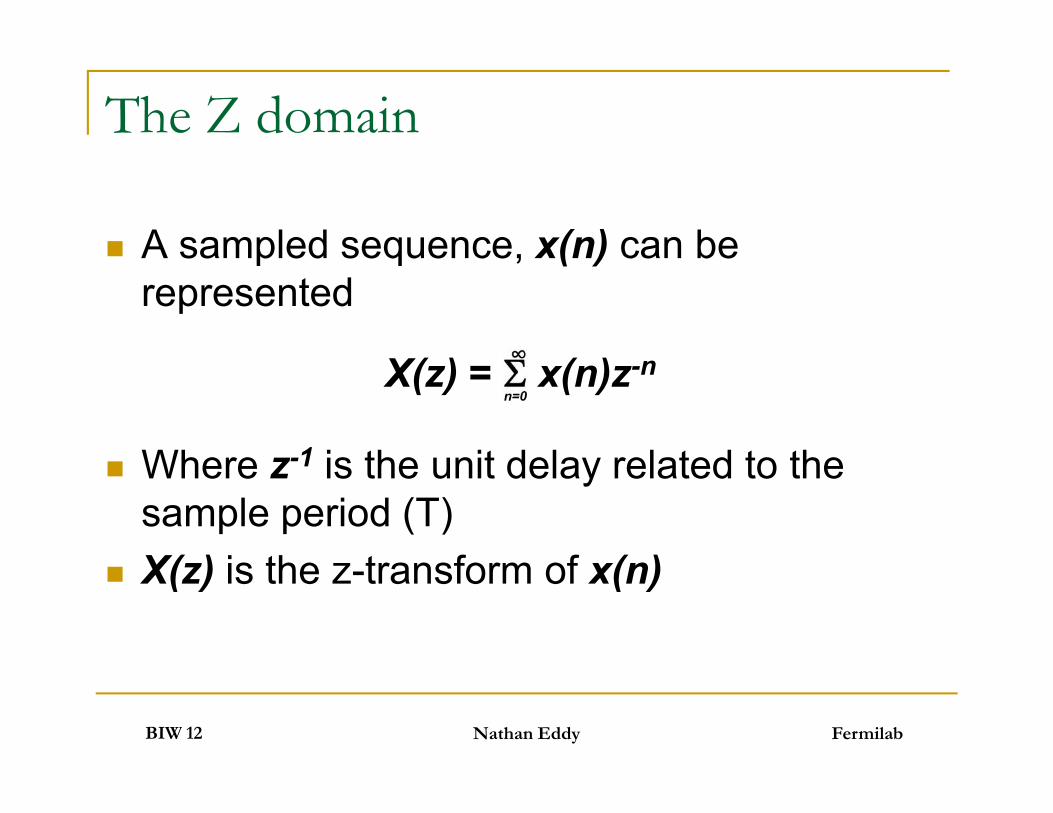
A sampled sequence, x(n) can berepresented
Where z-1 is the unit delay related to thesample period (T)
X(z) is the z-transform of x(n)
X(z) = x(n)z-n∞n=0
FermilabBIW 12
A sampled sequence, x(n) can berepresented
Where z-1 is the unit delay related to thesample period (T)
X(z) is the z-transform of x(n)
Nathan Eddy
Difference Eq & Transfer Function
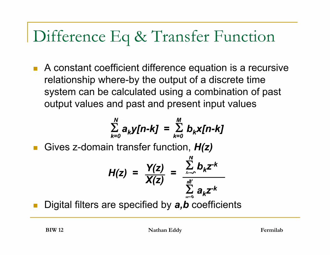
A constant coefficient difference equation is a recursiverelationship where-by the output of a discrete timesystem can be calculated using a combination of pastoutput values and past and present input values
Gives z-domain transfer function, H(z)
Digital filters are specified by a,b coefficients
aky[n-k] = bkx[n-k]N
k=0
M
k=0
FermilabBIW 12
A constant coefficient difference equation is a recursiverelationship where-by the output of a discrete timesystem can be calculated using a combination of pastoutput values and past and present input values
Gives z-domain transfer function, H(z)
Digital filters are specified by a,b coefficients
Nathan Eddy
aky[n-k] = bkx[n-k]
bkz-k
akz-k
Y(z)X(z)
H(z) = =
N
k=0
M
k=0
M
k=0
N
k=0
Infinite Impulse Response (IIR) Filter
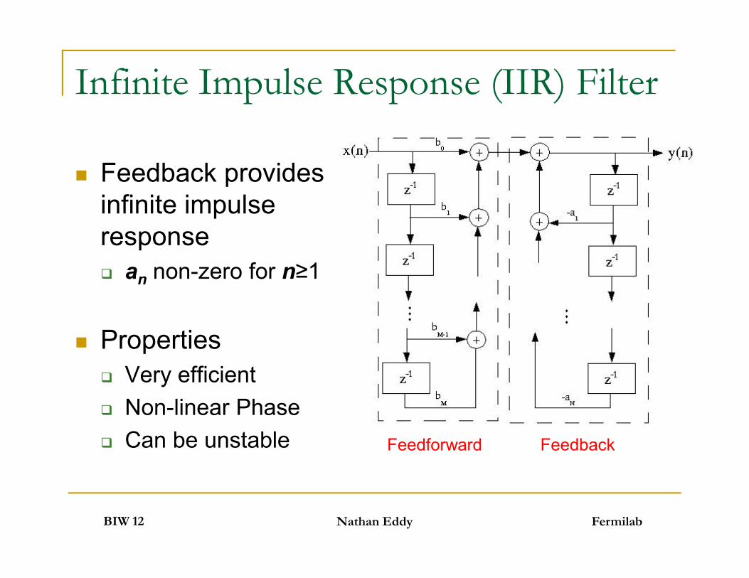
Feedback providesinfinite impulseresponse an non-zero for n≥1
Properties Very efficient Non-linear Phase Can be unstable
FermilabBIW 12
Feedback providesinfinite impulseresponse an non-zero for n≥1
Properties Very efficient Non-linear Phase Can be unstable
Nathan Eddy
Feedforward Feedback

Finite Impulse Response (FIR) Filter
Nth Order FIR filter
Just the feedforward block a0=1, all others zero
Has linear phase if coefficients are symmetric That is {b0,…,bN} = {bN,…,b0} No analog equivalent
FermilabBIW 12
Nth Order FIR filter
Just the feedforward block a0=1, all others zero
Has linear phase if coefficients are symmetric That is {b0,…,bN} = {bN,…,b0} No analog equivalent
Nathan Eddy

Cascade Integrating Comb (CIC) Filter
For an Nth Order CIC Filter, the transfer function is
Equivalent to N FIR filters with unit coefficients -> symmetric Linear Phase even though it has infinite response filter sections
Used as very efficient way to filter and change rate Can be used as Interpolation filter by reversing I & C sections
IntegratorH(z) = 1/(1+z-1)
Comb FilterH(z) = 1-z-RM
FermilabBIW 12
For an Nth Order CIC Filter, the transfer function is
Equivalent to N FIR filters with unit coefficients -> symmetric Linear Phase even though it has infinite response filter sections
Used as very efficient way to filter and change rate Can be used as Interpolation filter by reversing I & C sections
Nathan Eddy
H(z) = = ( z-k)N(1-z-RM)N
(1+z-1)NRM-1
k=0

Quadrature Signals, I & Q
Complex signal representation
In-Phase (real) & Quadrature (imaginary) I(t) = A(t)cos(φ(t)) Q(t) = A(t)sin(φ(t))
Real
Imag
A(t)φ(t)
Q(t)
I(t)
FermilabBIW 12
Complex signal representation
In-Phase (real) & Quadrature (imaginary) I(t) = A(t)cos(φ(t)) Q(t) = A(t)sin(φ(t))
Nathan Eddy
I(t)
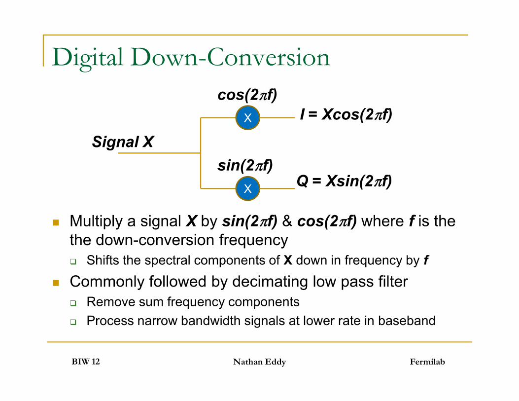
Digital Down-Conversion
Multiply a signal X by sin(2 f) & cos(2 f) where f is thethe down-conversion frequency Shifts the spectral components of X down in frequency by f
Commonly followed by decimating low pass filter Remove sum frequency components Process narrow bandwidth signals at lower rate in baseband
X
X
I = Xcos(2 f)
Q = Xsin(2 f)
cos(2 f)
sin(2 f)Signal X
FermilabBIW 12
Multiply a signal X by sin(2 f) & cos(2 f) where f is thethe down-conversion frequency Shifts the spectral components of X down in frequency by f
Commonly followed by decimating low pass filter Remove sum frequency components Process narrow bandwidth signals at lower rate in baseband
Nathan Eddy
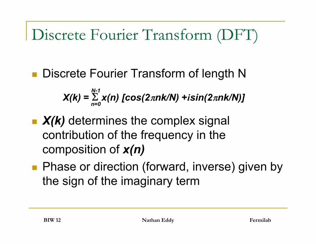
Discrete Fourier Transform (DFT)
Discrete Fourier Transform of length N
X(k) determines the complex signalcontribution of the frequency in thecomposition of x(n)
Phase or direction (forward, inverse) given bythe sign of the imaginary term
X(k) = x(n) [cos(2 nk/N) +isin(2 nk/N)]N-1
n=0
FermilabBIW 12
Discrete Fourier Transform of length N
X(k) determines the complex signalcontribution of the frequency in thecomposition of x(n)
Phase or direction (forward, inverse) given bythe sign of the imaginary term
Nathan Eddy
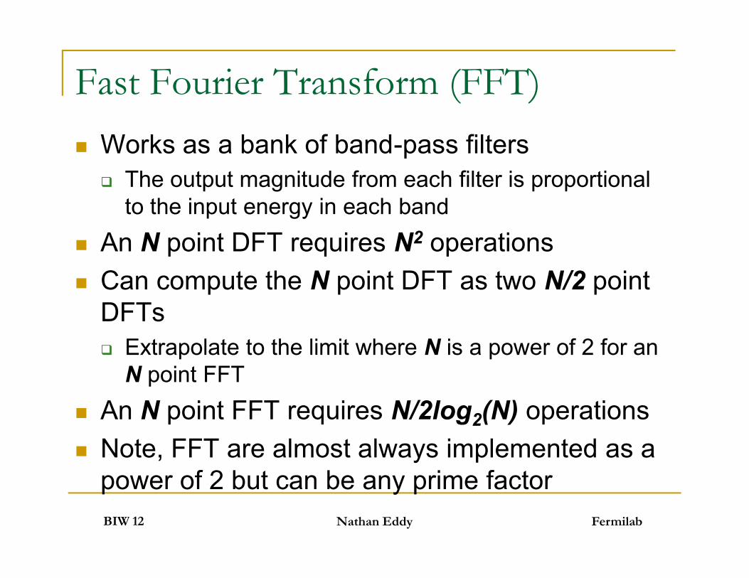
Fast Fourier Transform (FFT) Works as a bank of band-pass filters The output magnitude from each filter is proportional
to the input energy in each band An N point DFT requires N2 operations Can compute the N point DFT as two N/2 point
DFTs Extrapolate to the limit where N is a power of 2 for an
N point FFT An N point FFT requires N/2log2(N) operations Note, FFT are almost always implemented as a
power of 2 but can be any prime factorFermilabBIW 12
Works as a bank of band-pass filters The output magnitude from each filter is proportional
to the input energy in each band An N point DFT requires N2 operations Can compute the N point DFT as two N/2 point
DFTs Extrapolate to the limit where N is a power of 2 for an
N point FFT An N point FFT requires N/2log2(N) operations Note, FFT are almost always implemented as a
power of 2 but can be any prime factorNathan Eddy

Outline
Digital Signal Processing Basics
Modern FPGA Overview
Instrumentation Examples
FermilabBIW 12 Nathan Eddy
Digital Signal Processing Basics
Modern FPGA Overview
Instrumentation Examples
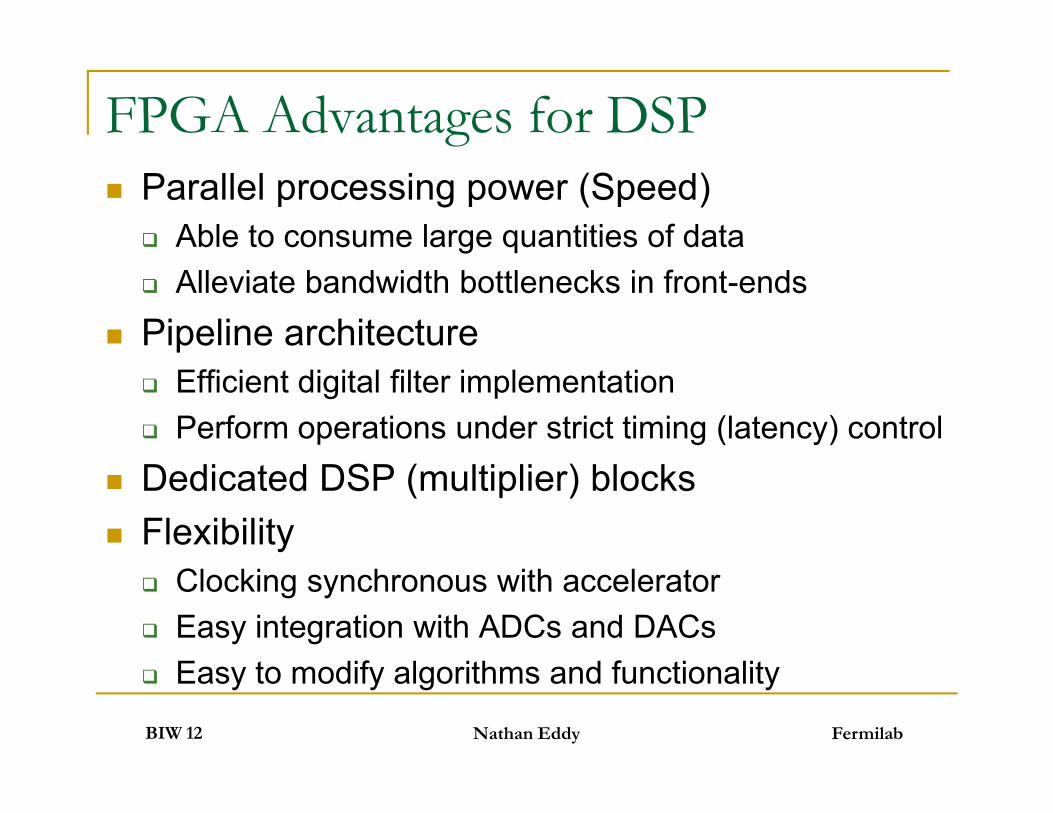
FPGA Advantages for DSP Parallel processing power (Speed) Able to consume large quantities of data Alleviate bandwidth bottlenecks in front-ends
Pipeline architecture Efficient digital filter implementation Perform operations under strict timing (latency) control
Dedicated DSP (multiplier) blocks Flexibility Clocking synchronous with accelerator Easy integration with ADCs and DACs Easy to modify algorithms and functionality
FermilabBIW 12
Parallel processing power (Speed) Able to consume large quantities of data Alleviate bandwidth bottlenecks in front-ends
Pipeline architecture Efficient digital filter implementation Perform operations under strict timing (latency) control
Dedicated DSP (multiplier) blocks Flexibility Clocking synchronous with accelerator Easy integration with ADCs and DACs Easy to modify algorithms and functionality
Nathan Eddy
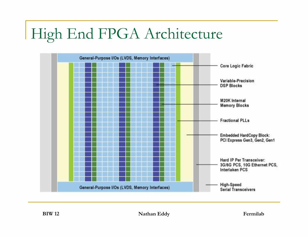
High End FPGA Architecture
FermilabBIW 12 Nathan Eddy

Flexible I/O Options
Dedicated hardware support for almost allstandard I/O protocols
Transceivers with equalization for fastdifferential serial I/O PCI Express, RapidIO, etc Support for over 20GBps links!
External memory interface support DDR, DDR2, DDR3
Speed and quantity of available I/O -> $$
FermilabBIW 12
Dedicated hardware support for almost allstandard I/O protocols
Transceivers with equalization for fastdifferential serial I/O PCI Express, RapidIO, etc Support for over 20GBps links!
External memory interface support DDR, DDR2, DDR3
Speed and quantity of available I/O -> $$
Nathan Eddy
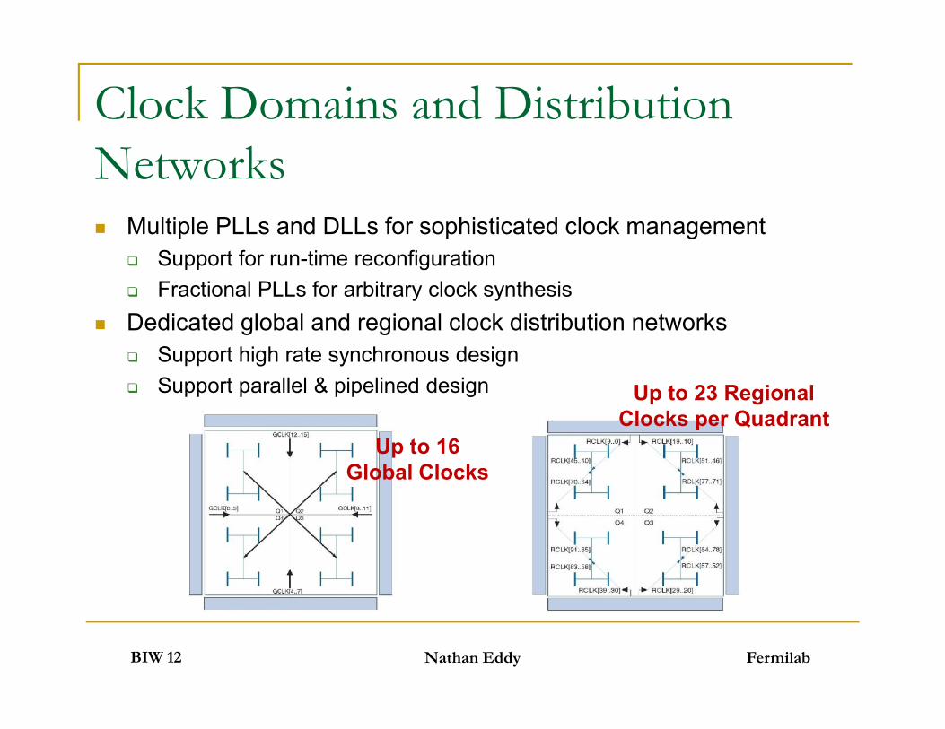
Clock Domains and DistributionNetworks Multiple PLLs and DLLs for sophisticated clock management
Support for run-time reconfiguration Fractional PLLs for arbitrary clock synthesis
Dedicated global and regional clock distribution networks Support high rate synchronous design Support parallel & pipelined design
FermilabBIW 12
Multiple PLLs and DLLs for sophisticated clock management Support for run-time reconfiguration Fractional PLLs for arbitrary clock synthesis
Dedicated global and regional clock distribution networks Support high rate synchronous design Support parallel & pipelined design
Nathan Eddy
Up to 16Global Clocks
Up to 23 RegionalClocks per Quadrant
Synchronous Design - Pipelining
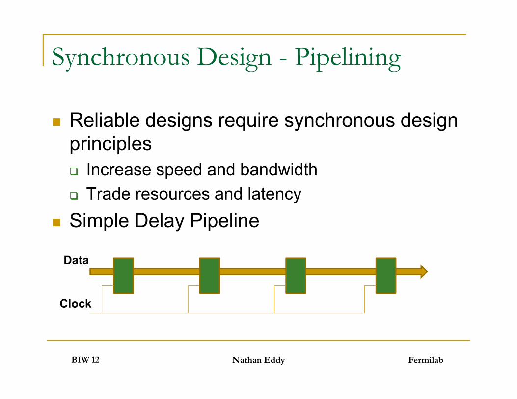
Reliable designs require synchronous designprinciples Increase speed and bandwidth Trade resources and latency
Simple Delay Pipeline
FermilabBIW 12
Reliable designs require synchronous designprinciples Increase speed and bandwidth Trade resources and latency
Simple Delay Pipeline
Nathan Eddy
Data
Clock
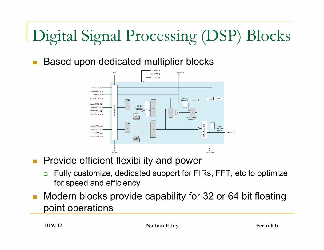
Based upon dedicated multiplier blocks
Provide efficient flexibility and power Fully customize, dedicated support for FIRs, FFT, etc to optimize
for speed and efficiency
Modern blocks provide capability for 32 or 64 bit floatingpoint operations
Digital Signal Processing (DSP) Blocks
FermilabBIW 12
Based upon dedicated multiplier blocks
Provide efficient flexibility and power Fully customize, dedicated support for FIRs, FFT, etc to optimize
for speed and efficiency
Modern blocks provide capability for 32 or 64 bit floatingpoint operations
Nathan Eddy
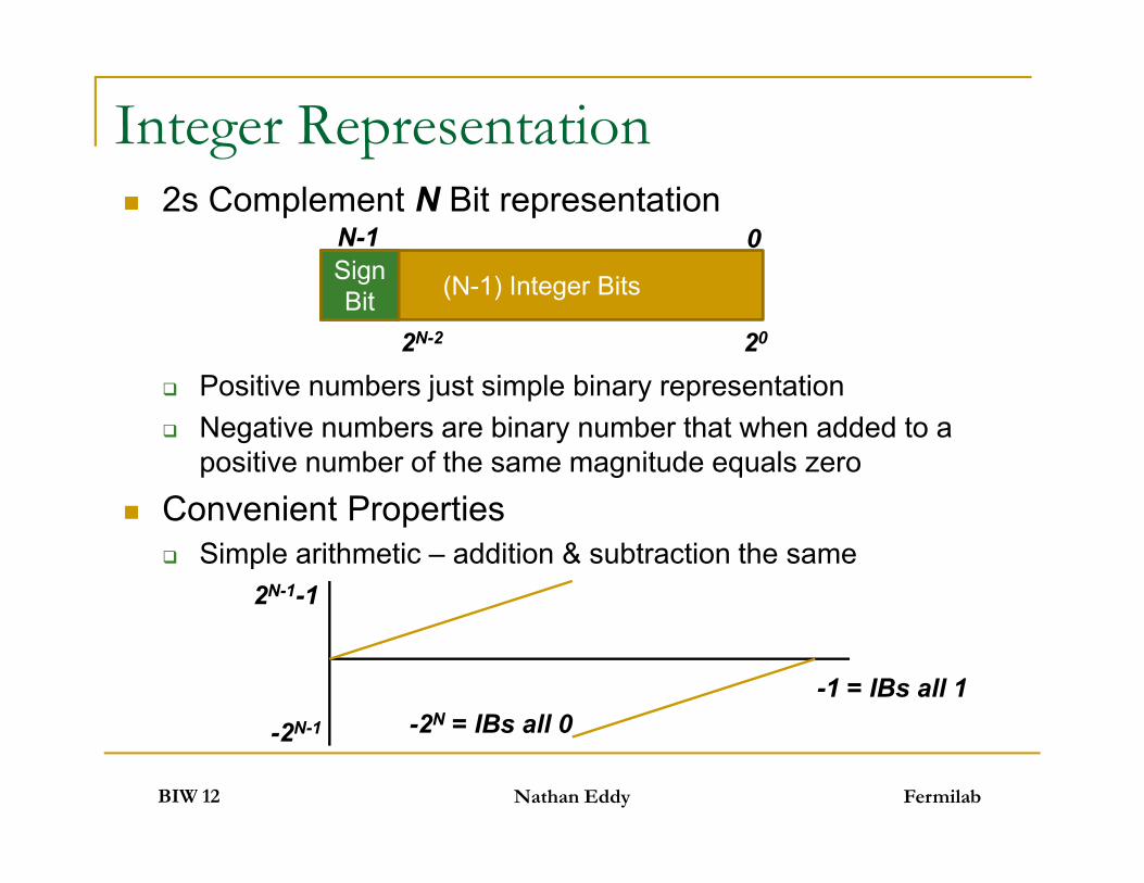
2s Complement N Bit representation
Positive numbers just simple binary representation Negative numbers are binary number that when added to a
positive number of the same magnitude equals zero
Convenient Properties Simple arithmetic – addition & subtraction the same
Integer Representation
(N-1) Integer BitsSignBit
0N-1
2N-2 20
FermilabBIW 12
2s Complement N Bit representation
Positive numbers just simple binary representation Negative numbers are binary number that when added to a
positive number of the same magnitude equals zero
Convenient Properties Simple arithmetic – addition & subtraction the same
Nathan Eddy
2N-1-1
-2N-1
-1 = IBs all 1-2N = IBs all 0
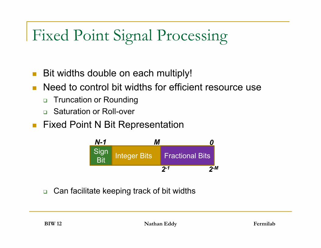
Fixed Point Signal Processing
Bit widths double on each multiply! Need to control bit widths for efficient resource use
Truncation or Rounding Saturation or Roll-over
Fixed Point N Bit Representation
Can facilitate keeping track of bit widths
FermilabBIW 12
Bit widths double on each multiply! Need to control bit widths for efficient resource use
Truncation or Rounding Saturation or Roll-over
Fixed Point N Bit Representation
Can facilitate keeping track of bit widths
Nathan Eddy
Integer BitsSignBit Fractional Bits
0N-1 M
2-1 2-M

Floating Point Representation IEEE-754 Standard Followed
32 bit – Single Precision 8 bit Exponent & 23 bit Mantissa
64 bit – Double Precision 11 bit Exponent & 52 bit Mantissa
Single-Extended Precision Exponent and Mantissa widths are not fixed Minimum 11 Exponent Bits (Exponent<Mantissa) Minimum 31Mantissa Bits Total Bits at least 43 up to 64
ExponentSignBit Mantissa
FermilabBIW 12
IEEE-754 Standard Followed
32 bit – Single Precision 8 bit Exponent & 23 bit Mantissa
64 bit – Double Precision 11 bit Exponent & 52 bit Mantissa
Single-Extended Precision Exponent and Mantissa widths are not fixed Minimum 11 Exponent Bits (Exponent<Mantissa) Minimum 31Mantissa Bits Total Bits at least 43 up to 64
Nathan Eddy

Running Average Example Can implement an N sample running average as
an FIR with N taps with coefficients of 1/N
Can be efficiently implemented using twoaccumulators and a delay line
FermilabBIW 12
Can implement an N sample running average asan FIR with N taps with coefficients of 1/N
Can be efficiently implemented using twoaccumulators and a delay line
Nathan Eddy
x[n] z-N Acc
Acc- /N y[n]

Intellectual Property (IP) Cores Functional cores which can be used to
greatly speed up and simplify the designprocess
Each FPGA manufacturer provides cores forall basic components PLLs, RAM, FIFOs, Flip-Flops, etc Accumulators, Add, Sub, Multiply, Divide, etc Take advantage of chip resources
Advanced cores available for almost any task Simple implementation via GUI parametrization
FermilabBIW 12
Functional cores which can be used togreatly speed up and simplify the designprocess
Each FPGA manufacturer provides cores forall basic components PLLs, RAM, FIFOs, Flip-Flops, etc Accumulators, Add, Sub, Multiply, Divide, etc Take advantage of chip resources
Advanced cores available for almost any task Simple implementation via GUI parametrization
Nathan Eddy

Embedded Systems
Hard Core Embedded processoris a dedicated physicalcomponent of the chip, separatefrom the programmable logic 2-4 times faster than Soft Core More efficient if you need a
processor Soft Core Embedded processor
is built out of the programmablelogic on the chip A 32 bit RISC processor uses
about few percent of totalresources
Have option to re-allocateresources if processor notneeded
Hard Core Resource Allocation
FermilabBIW 12 Nathan Eddy
Hard Core Embedded processoris a dedicated physicalcomponent of the chip, separatefrom the programmable logic 2-4 times faster than Soft Core More efficient if you need a
processor Soft Core Embedded processor
is built out of the programmablelogic on the chip A 32 bit RISC processor uses
about few percent of totalresources
Have option to re-allocateresources if processor notneeded
Soft Core Resource Allocation
System On a Programmable Chip(SOPC) A wide variety of design tools and options
available Pure HDL entry – still possible
Focus upon developing System On aProgrammable Chip Aim to simplify the design process as chip
architectures become more complicated Tightly couple design and simulation at all
levels
FermilabBIW 12
A wide variety of design tools and optionsavailable Pure HDL entry – still possible
Focus upon developing System On aProgrammable Chip Aim to simplify the design process as chip
architectures become more complicated Tightly couple design and simulation at all
levels
Nathan Eddy

Outline
Digital Signal Processing Basics
Modern FPGA Overview
Instrumentation Examples
FermilabBIW 12 Nathan Eddy
Digital Signal Processing Basics
Modern FPGA Overview
Instrumentation Examples

Fermilab Booster Digital Damper
FermilabBIW 12 Nathan Eddy

Digital Damper Board
4 DACsDDR
SoDIMMBig
FPGA
FermilabBIW 12 Nathan Eddy
4 ADCs
BigFPGA
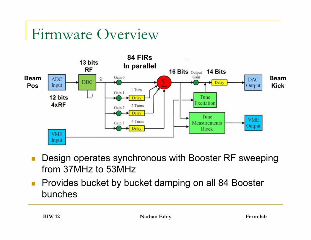
Firmware Overview84 FIRs
In parallelBeamPos
BeamKick
FermilabBIW 12
Design operates synchronous with Booster RF sweepingfrom 37MHz to 53MHz
Provides bucket by bucket damping on all 84 Boosterbunches
Nathan Eddy
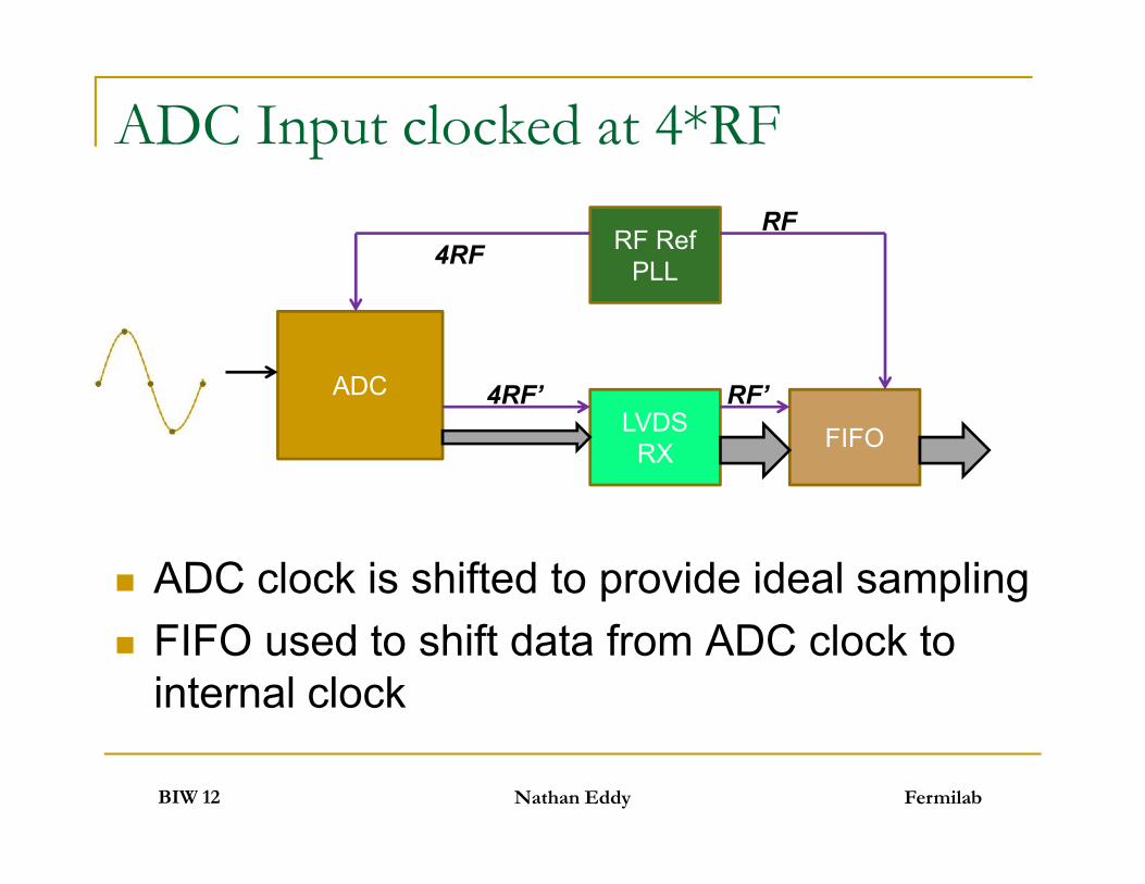
ADC Input clocked at 4*RF
ADC
RF RefPLL
LVDSRX FIFO
4RF
4RF’ RF’
RF
FermilabBIW 12
ADC clock is shifted to provide ideal sampling FIFO used to shift data from ADC clock to
internal clock
Nathan Eddy
LVDSRX FIFO
RF Reference PLL
Use one of the Enhanced PLLs Dedicated clock pin for RF Reference Directly connected to clock output pins for each
ADC clock Real-time reconfigurability Use to adjust phase of ADC clock in 15º
increments (~200ps @ 50Mhz) Instantiated with parametrized IP
FermilabBIW 12
Use one of the Enhanced PLLs Dedicated clock pin for RF Reference Directly connected to clock output pins for each
ADC clock Real-time reconfigurability Use to adjust phase of ADC clock in 15º
increments (~200ps @ 50Mhz) Instantiated with parametrized IP
Nathan Eddy
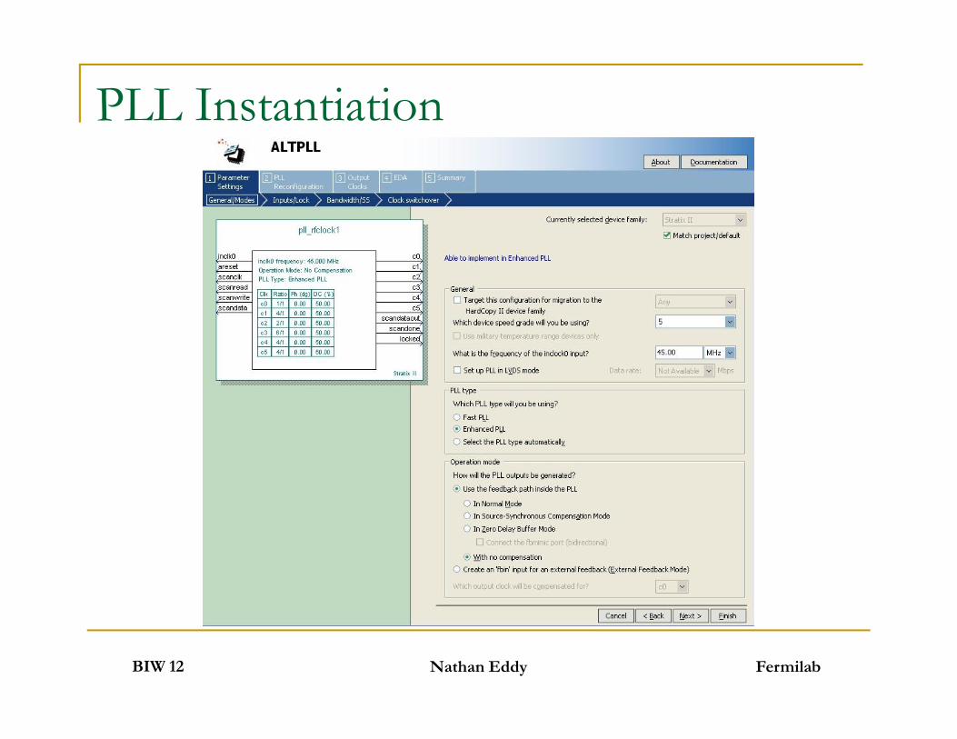
PLL Instantiation
FermilabBIW 12 Nathan Eddy

PLL Instantiation
FermilabBIW 12 Nathan Eddy
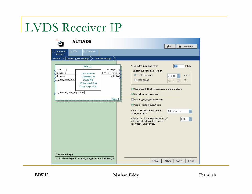
LVDS Receiver
Instantiated with parametrized IP Able to take full advantage of built in RX
blocks Dynamic Phase Alignment circuitry Automatically de-serialize data from 4*RF rate
to 4 time multi-plexed samples at RF rate No need to worry about timing constraints!
FermilabBIW 12
Instantiated with parametrized IP Able to take full advantage of built in RX
blocks Dynamic Phase Alignment circuitry Automatically de-serialize data from 4*RF rate
to 4 time multi-plexed samples at RF rate No need to worry about timing constraints!
Nathan Eddy

LVDS Receiver IP
FermilabBIW 12 Nathan Eddy
LVDS Receiver IP
FermilabBIW 12 Nathan Eddy

LVDS Receiver IP
FermilabBIW 12 Nathan Eddy

Programmable Delay Dual-port RAM to provide programmable delay
Offset read & write pointer to requested delay value Reset Read Counter to zero when Write Counter = Delay-1
Maximum delay set by the depth of the RAM
WriteCounter
ClockData Clock
FermilabBIW 12 Nathan Eddy
Dual-portRAM
WriteCounter
Clock
WrAddr
WrData
ReadCounter
RdAddrRdData
Data In
Data Out
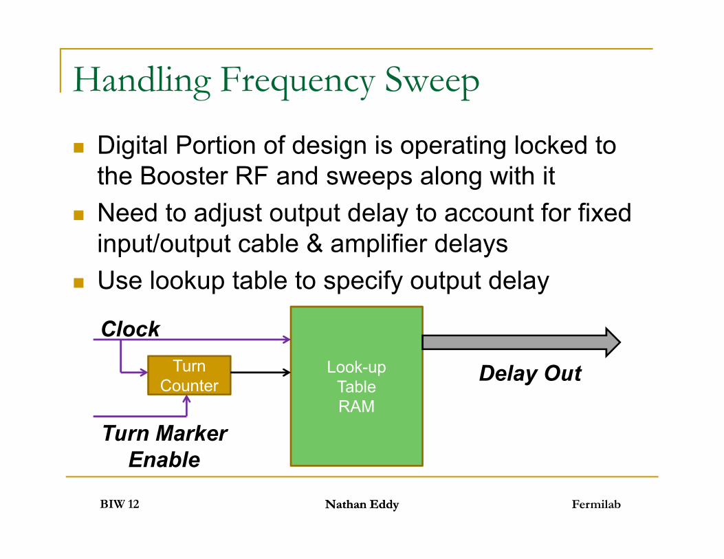
Handling Frequency Sweep
Digital Portion of design is operating locked tothe Booster RF and sweeps along with it
Need to adjust output delay to account for fixedinput/output cable & amplifier delays
Use lookup table to specify output delay
FermilabBIW 12
Digital Portion of design is operating locked tothe Booster RF and sweeps along with it
Need to adjust output delay to account for fixedinput/output cable & amplifier delays
Use lookup table to specify output delay
Nathan EddyNathan Eddy
Look-upTableRAM
TurnCounter Delay Out
Clock
Turn MarkerEnable

Implementation of “Fine” Delay
Filter produces kick for each RF bucket Operate DAC at 12*RF clock rate
Can shift data fed to LVDS Transmitter toprovide RF/12 delay resolution
Kick @RF Kick @12*RF
FermilabBIW 12
Filter produces kick for each RF bucket Operate DAC at 12*RF clock rate
Can shift data fed to LVDS Transmitter toprovide RF/12 delay resolution
Nathan Eddy
Latch12
Kick @RFLVDS
TX
Kick @12*RF
To DAC
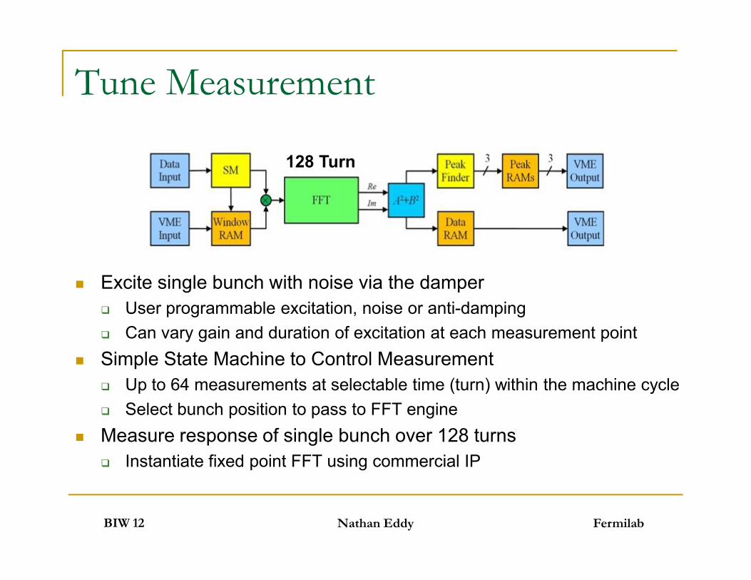
Tune Measurement
Excite single bunch with noise via the damper User programmable excitation, noise or anti-damping Can vary gain and duration of excitation at each measurement point
Simple State Machine to Control Measurement Up to 64 measurements at selectable time (turn) within the machine cycle Select bunch position to pass to FFT engine
Measure response of single bunch over 128 turns Instantiate fixed point FFT using commercial IP
128 Turn
FermilabBIW 12
Excite single bunch with noise via the damper User programmable excitation, noise or anti-damping Can vary gain and duration of excitation at each measurement point
Simple State Machine to Control Measurement Up to 64 measurements at selectable time (turn) within the machine cycle Select bunch position to pass to FFT engine
Measure response of single bunch over 128 turns Instantiate fixed point FFT using commercial IP
Nathan Eddy

Tune Measurement
FermilabBIW 12 Nathan Eddy
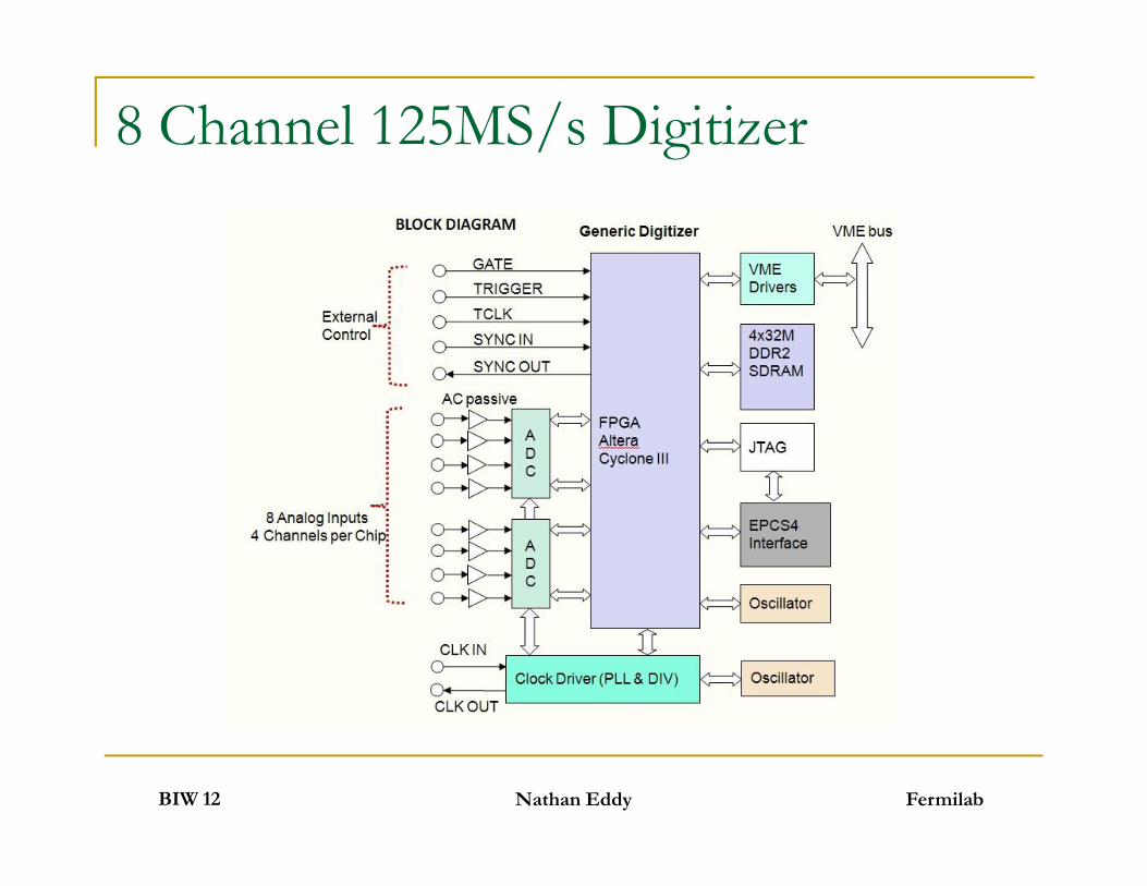
8 Channel 125MS/s Digitizer
FermilabBIW 12 Nathan Eddy

Digital BPM Receiver Firmware
FermilabBIW 12 Nathan Eddy

Narrowband (Closed Orbit) Filter
BeamCalib
FermilabBIW 12
Digital Down Converter (DDC) Section 32 separate filter paths simultaneously 8 channels, I&Q, 2 frequencies (beam, calibration)
CIC filters operating in parallel at 71MHz Serial FIR filter at 4.2KHz
Nathan Eddy
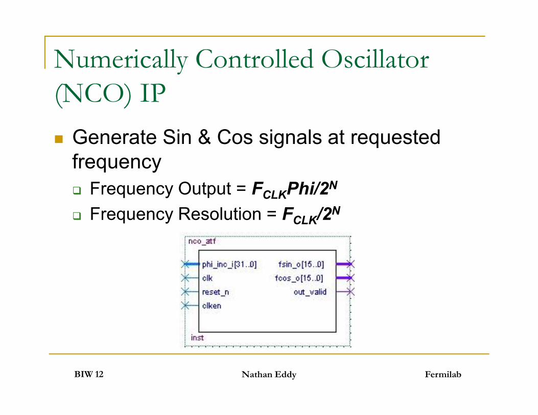
Numerically Controlled Oscillator(NCO) IP Generate Sin & Cos signals at requested
frequency Frequency Output = FCLKPhi/2N
Frequency Resolution = FCLK/2N
FermilabBIW 12
Generate Sin & Cos signals at requestedfrequency Frequency Output = FCLKPhi/2N
Frequency Resolution = FCLK/2N
Nathan Eddy
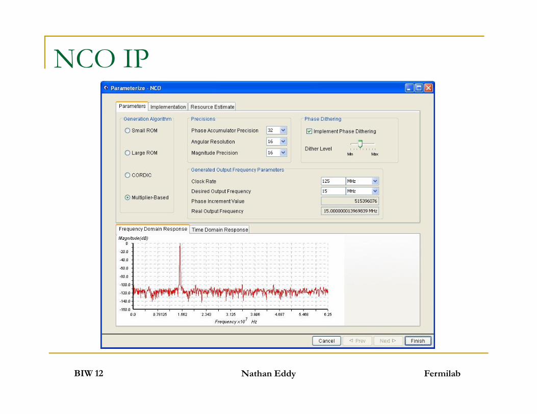
NCO IP
FermilabBIW 12 Nathan Eddy

DDC Quantization Error
Will always have a slight offset between theNCO frequency and the beam frequency
Easy solution is to offset the NCO frequencyto get an integer number of periods in theaveraging window
FermilabBIW 12
Will always have a slight offset between theNCO frequency and the beam frequency
Easy solution is to offset the NCO frequencyto get an integer number of periods in theaveraging window
Nathan Eddy
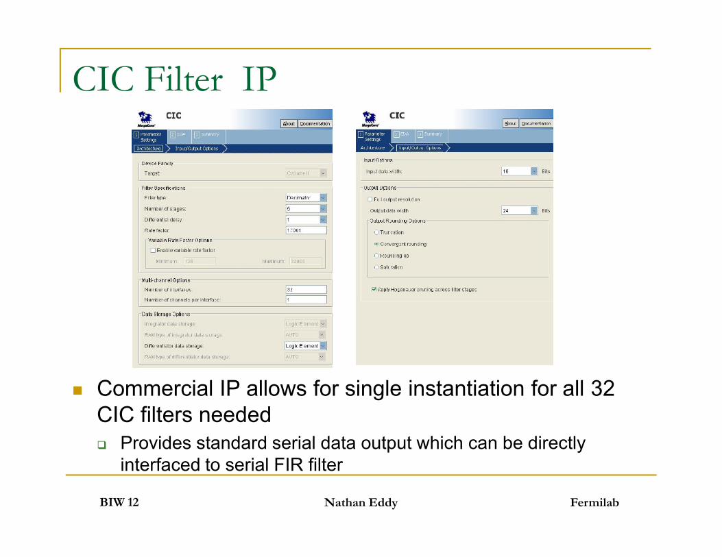
CIC Filter IP
FermilabBIW 12
Commercial IP allows for single instantiation for all 32CIC filters needed Provides standard serial data output which can be directly
interfaced to serial FIR filter
Nathan Eddy

FIR Filter IP
FermilabBIW 12
Provides simple filter design tool or ability to import filtercoefficients
Option to allow modification of coefficients
Nathan Eddy

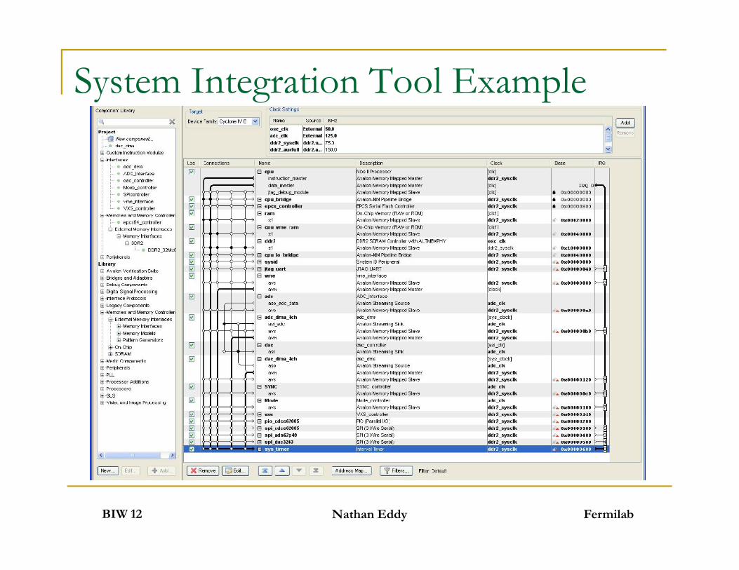
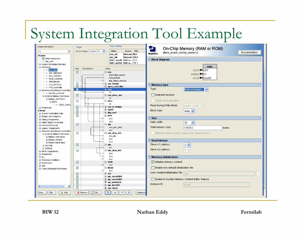
System Integration Tools Streamline system integration and design
Connect standard interfaces Internal memory, external memory, configuration devices, etc
Connect custom interfaces Easy CPU integration Handles addressing & interrupts Even generates drivers for system components!
Use well defined interfaces Generates all logic for system interconnects! Handles all the timing - clock domains, multiplexing, etc Built in error checking at compile time
Facilitates implementing re-usable HDL blocks andgroup design methodologies
FermilabBIW 12
Streamline system integration and design Connect standard interfaces Internal memory, external memory, configuration devices, etc
Connect custom interfaces Easy CPU integration Handles addressing & interrupts Even generates drivers for system components!
Use well defined interfaces Generates all logic for system interconnects! Handles all the timing - clock domains, multiplexing, etc Built in error checking at compile time
Facilitates implementing re-usable HDL blocks andgroup design methodologies
Nathan Eddy
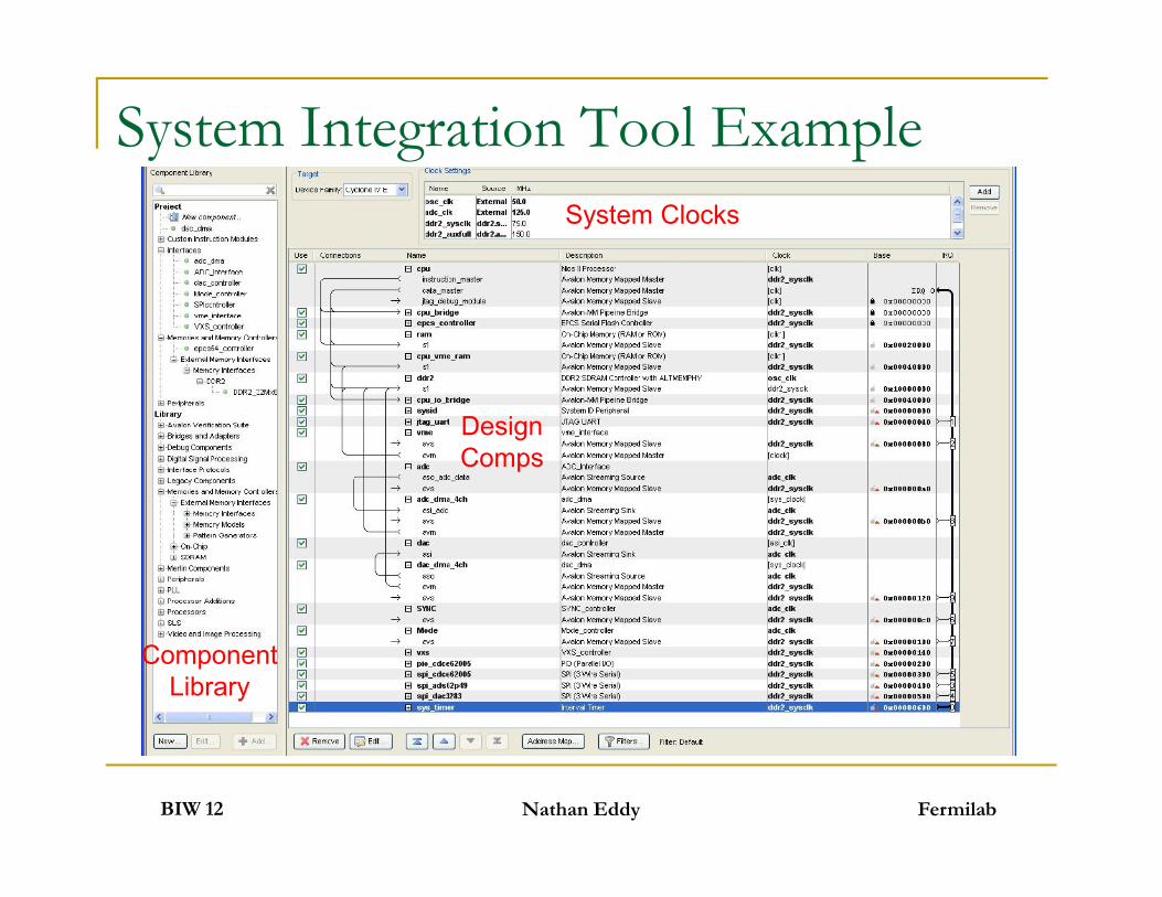
System Integration Tool ExampleSystem Clocks
DesignComps
FermilabBIW 12 Nathan Eddy
ComponentLibrary
DesignComps
System Integration Tool Example
FermilabBIW 12 Nathan Eddy
System Integration Tool Example
FermilabBIW 12 Nathan Eddy

Summary - the FPGA Pitch Sure things…
FPGA are now the acknowledged leader of cutting edge fast DSPapplications where speed and flexibility are needed
Accelerator Control and Instrumentation is already using FPGAs toimplement fast online applications, especially feedback & control
The size, speed, and feature sets continue to grow by leaps and bounds Today’s mid level chips are offering features only available in high end chips
just a few years ago at a fraction of the cost Design tools are getting closer to traditional programming and becoming
easier to use Looks promising…
Use of FPGA’s to implement online orbit measurements and opticcalcuations which could be used for realtime feedback
The next step is cluster and mesh architectures using FPGAs to furtherincrease the processing power
It could happen.. FPGA based co-processors for dedicated calculations FPGA based super computers which configure their hardware to optimize
the performance for the algorithms being used
FermilabBIW 12 Nathan Eddy
Sure things… FPGA are now the acknowledged leader of cutting edge fast DSP
applications where speed and flexibility are needed Accelerator Control and Instrumentation is already using FPGAs to
implement fast online applications, especially feedback & control The size, speed, and feature sets continue to grow by leaps and bounds Today’s mid level chips are offering features only available in high end chips
just a few years ago at a fraction of the cost Design tools are getting closer to traditional programming and becoming
easier to use Looks promising…
Use of FPGA’s to implement online orbit measurements and opticcalcuations which could be used for realtime feedback
The next step is cluster and mesh architectures using FPGAs to furtherincrease the processing power
It could happen.. FPGA based co-processors for dedicated calculations FPGA based super computers which configure their hardware to optimize
the performance for the algorithms being used
Thanks for Your Attention!
FermilabBIW 12 Nathan Eddy


