
2/4/2018
1
Guidelines for Slope Stability Improvement with Lightweight FillSteven Bartlett, University of Utah
1
Design methodology overviewDavid Arellano, University of Memphis
2
2/4/2018
2
Outline
Overview Design methodologyConstruction practices & cost considerations Update on previous standard for slope stability
applicationsQuestion and answer session
3
OverviewProblem Statement
New roadway alignments and/or widening of existing roadway embankments will be required to solve the current and future highway capacity problem.
Roadway construction often exacerbates the landslide problem in hilly areas by alternating the landscape, slopes, and drainages and by changing and channeling runoff (Spiker and Gori, 2003).
Geofoam provides an alternative slope stabilization and repair technique that is based on reducing the driving forces.
4
2/4/2018
3
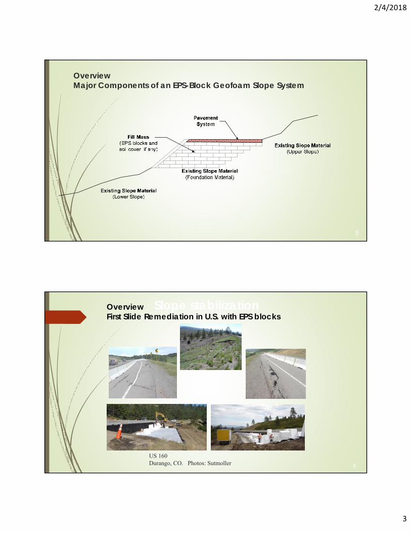
OverviewMajor Components of an EPS-Block Geofoam Slope System
5
US 160Durango, CO. Photos: Sutmoller
Slope stabilization
6
OverviewFirst Slide Remediation in U.S. with EPS blocks
2/4/2018
4
7
AL DOTAL DOT
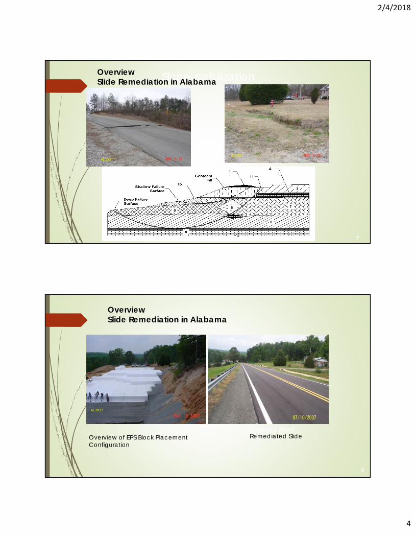
Slope stabilizationOverviewSlide Remediation in Alabama
Overview of EPS Block Placement Configuration
8
AL DOT
Completed RoadRemediated Slide
OverviewSlide Remediation in Alabama

2/4/2018
5
Outline
Overview Design methodologyConstruction practices & other considerationsQuestion and answers
9
NCHRP 24-11(02)
10
a) Slope-sided fill.
b) Vertical-sided fill (Geofoam wall).
Design Methodology
2/4/2018
6
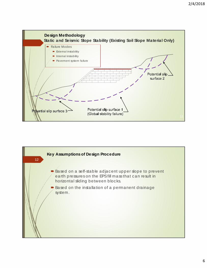
Static and Seismic Slope Stability (Existing Soil Slope Material Only)
11
Failure Modes External instability Internal instability Pavement system failure
Design Methodology
Key Assumptions of Design Procedure
Based on a self-stable adjacent upper slope to prevent earth pressures on the EPS fill mass that can result in horizontal sliding between blocks.
Based on the installation of a permanent drainage system.
12
2/4/2018
7
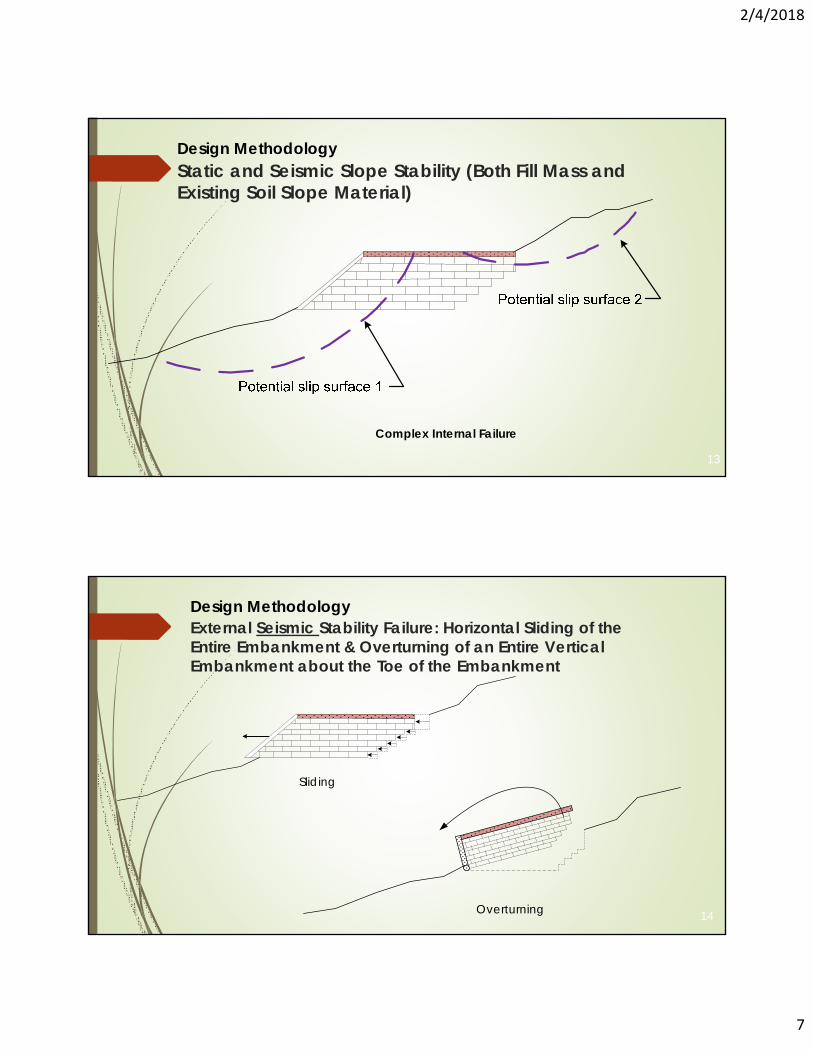
Static and Seismic Slope Stability (Both Fill Mass and Existing Soil Slope Material)
13
Complex Internal Failure
Design Methodology
External Seismic Stability Failure: Horizontal Sliding of the Entire Embankment & Overturning of an Entire Vertical Embankment about the Toe of the Embankment
14
Sliding
Overturning
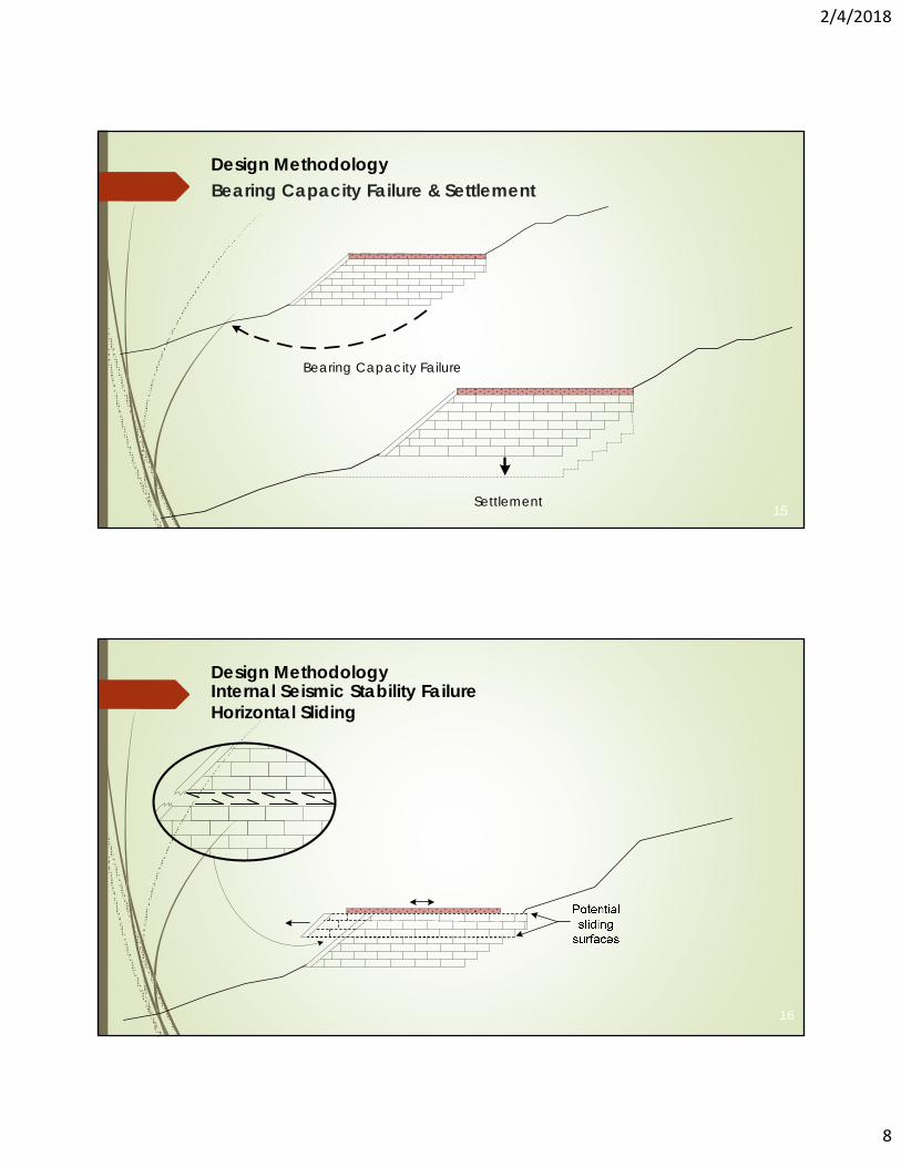
Design Methodology
2/4/2018
8
Bearing Capacity Failure & Settlement
15
Bearing Capacity Failure
Settlement
Design Methodology
Internal Seismic Stability Failure Horizontal Sliding
16
Design Methodology
2/4/2018
9
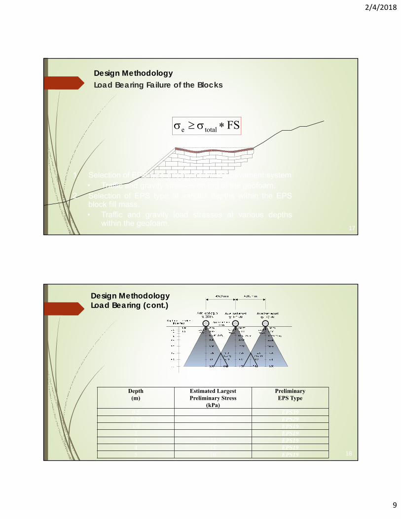
Load Bearing Failure of the Blocks
17
e total FS
1. Selection of EPS type directly below the pavement system• Traffic and gravity stresses on top of the geofoam.
2. Selection of EPS type at various depths within the EPSblock fill mass.• Traffic and gravity load stresses at various depths
within the geofoam.
Design Methodology
Depth(m)
Estimated Largest Preliminary Stress
(kPa)
PreliminaryEPS Type
0.5 96 EPS390.75 58 EPS291.0 38 EPS192 26 EPS193 13 EPS194 15 EPS195 10 EPS19 18
Design MethodologyLoad Bearing (cont.)
2/4/2018
10
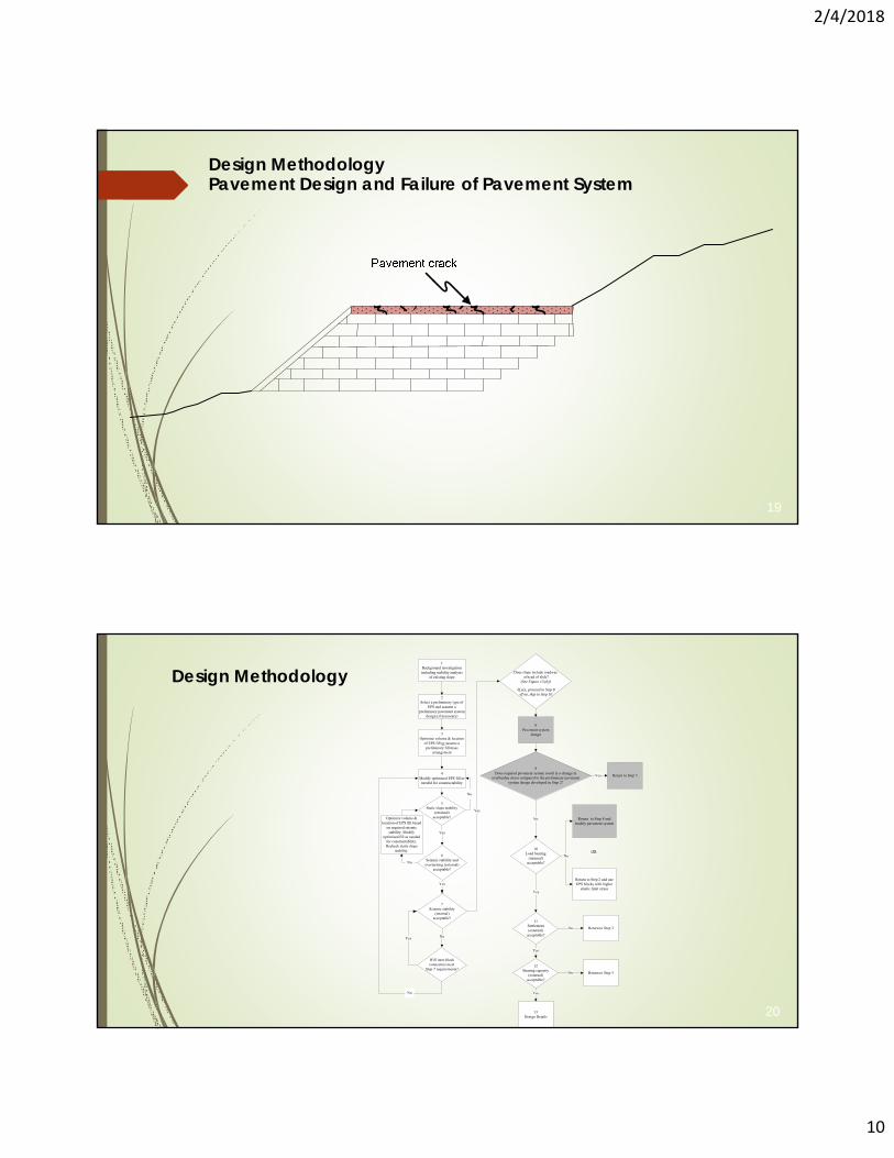
Pavement Design and Failure of Pavement System
19
Design Methodology
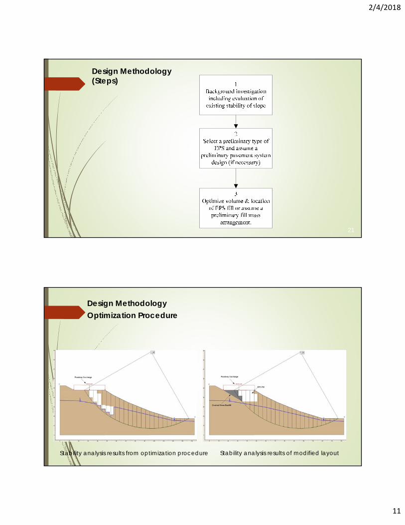
1Background investigation including stability analysis
of existing slope
2Select a preliminary type of
EPS and assume a preliminary pavement system
design (if necessary)
3Optimize volume & location
of EPS fill or assume a preliminary fill mass
arrangement
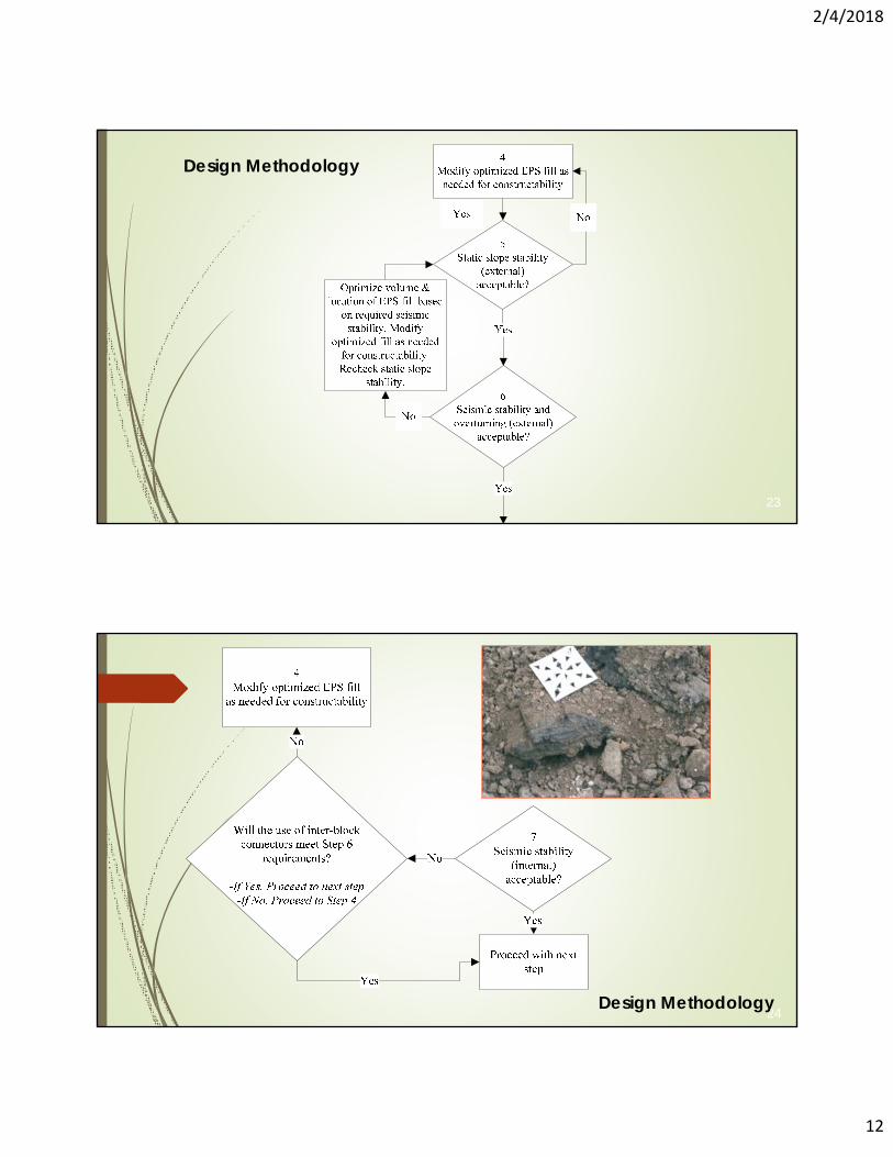
5Static slope stability
(external)acceptable?
6Seismic stability and overturning (external)
acceptable?
7Seismic stability
(internal)acceptable?
8Pavement system
design
9Does required pavement system result in a change in
overburden stress compared to the preliminary pavement system design developed in Step 2?
Return to Step 5
Yes
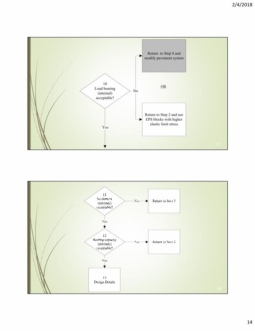
11Settlement(external)
acceptable?
12Bearing capacity
(external)acceptable?
10Load bearing
(internal)acceptable?
13Design Details
No
Yes
Yes
Yes
Yes
Return to Step 3
Return to Step 3
No
No
No
No
Yes
Yes
OR
4Modify optimized EPS fill as
needed for constructability
Yes
No
Will inter-block connectors meet
Step 7 requirements?
Does slope include roadwayat head of slide?
(See Figure 13 (b))
-If yes, proceed to Step 8-If no, skip to Step 10
Return to Step 8 and modify pavement system
Return to Step 2 and use EPS blocks with higher
elastic limit stress
Optimize volume & location of EPS fill based
on required seismic stability. Modify
optimized fill as needed for constructability. Recheck static slope
stability.
No
No
20
Design Methodology
2/4/2018
11
21
Design Methodology(Steps)
Optimization Procedure
Stability analysis results from optimization procedure Stability analysis results of modified layout
Design Methodology
2/4/2018
12
23
Design Methodology
24Design Methodology
2/4/2018
13
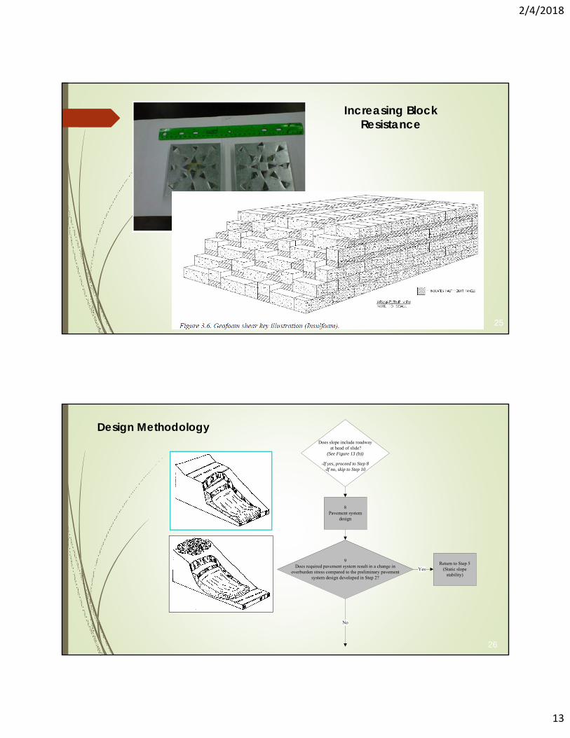
25
Increasing Block Resistance
8Pavement system
design
9Does required pavement system result in a change in
overburden stress compared to the preliminary pavement system design developed in Step 2?
Return to Step 5(Static slope
stability)
No
Yes
Does slope include roadwayat head of slide?
(See Figure 13 (b))
-If yes, proceed to Step 8-If no, skip to Step 10
26
Design Methodology
2/4/2018
14
10Load bearing
(internal)acceptable?
Yes
NoOR
Return to Step 8 and modify pavement system
Return to Step 2 and use EPS blocks with higher
elastic limit stress
27
28
2/4/2018
15
Outline
Overview Design methodologyConstruction practices & other considerationsQuestion and answers
29
30
AL DOT
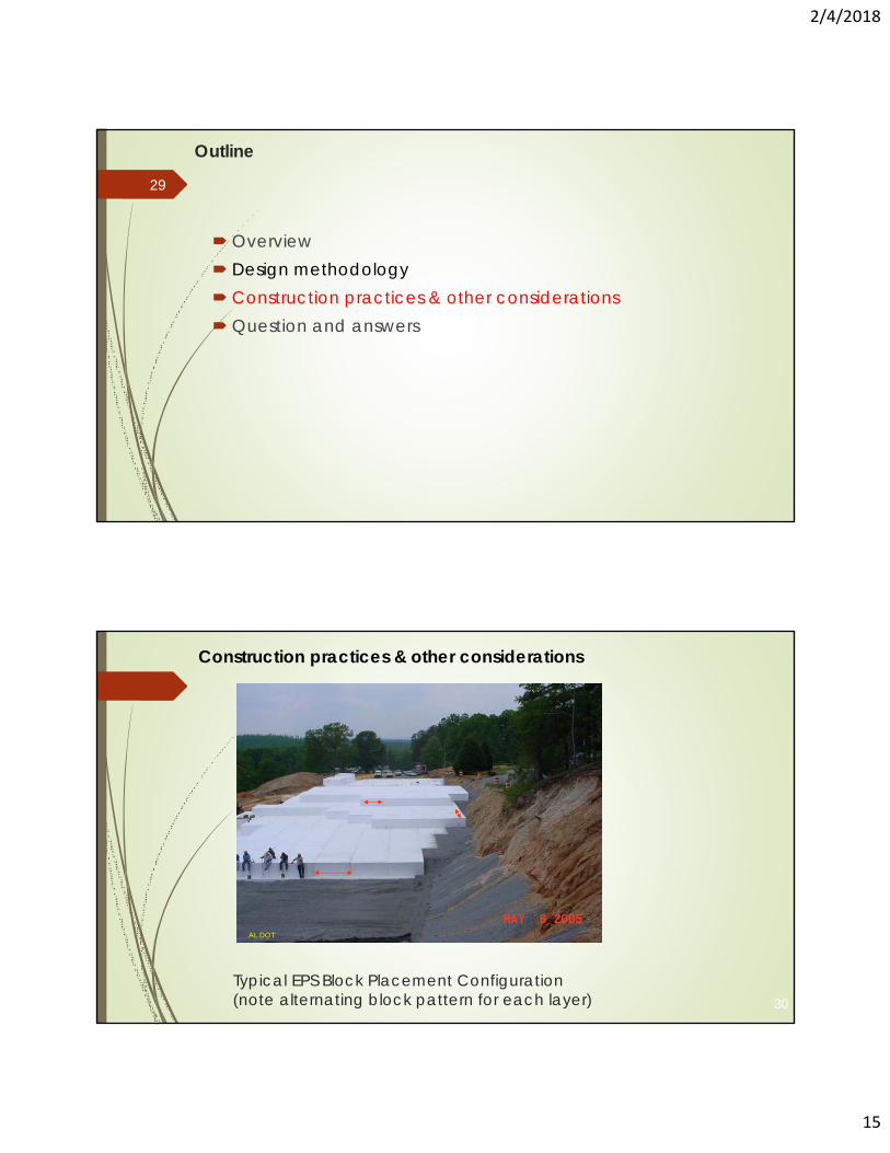
Typical EPS Block Placement Configuration(note alternating block pattern for each layer)
Construction practices & other considerations
2/4/2018
16
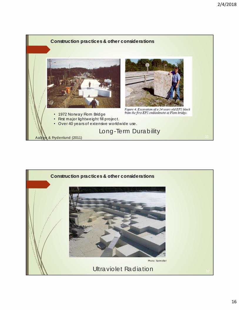
Long-Term DurabilityAaboe & Frydenlund (2011)
• 1972 Norway Flom Bridge• First major lightweight fill project.• Over 40 years of extensive worldwide use.
31
Construction practices & other considerations
Ultraviolet RadiationPhoto: Sutmoller
32
Construction practices & other considerations
2/4/2018
17
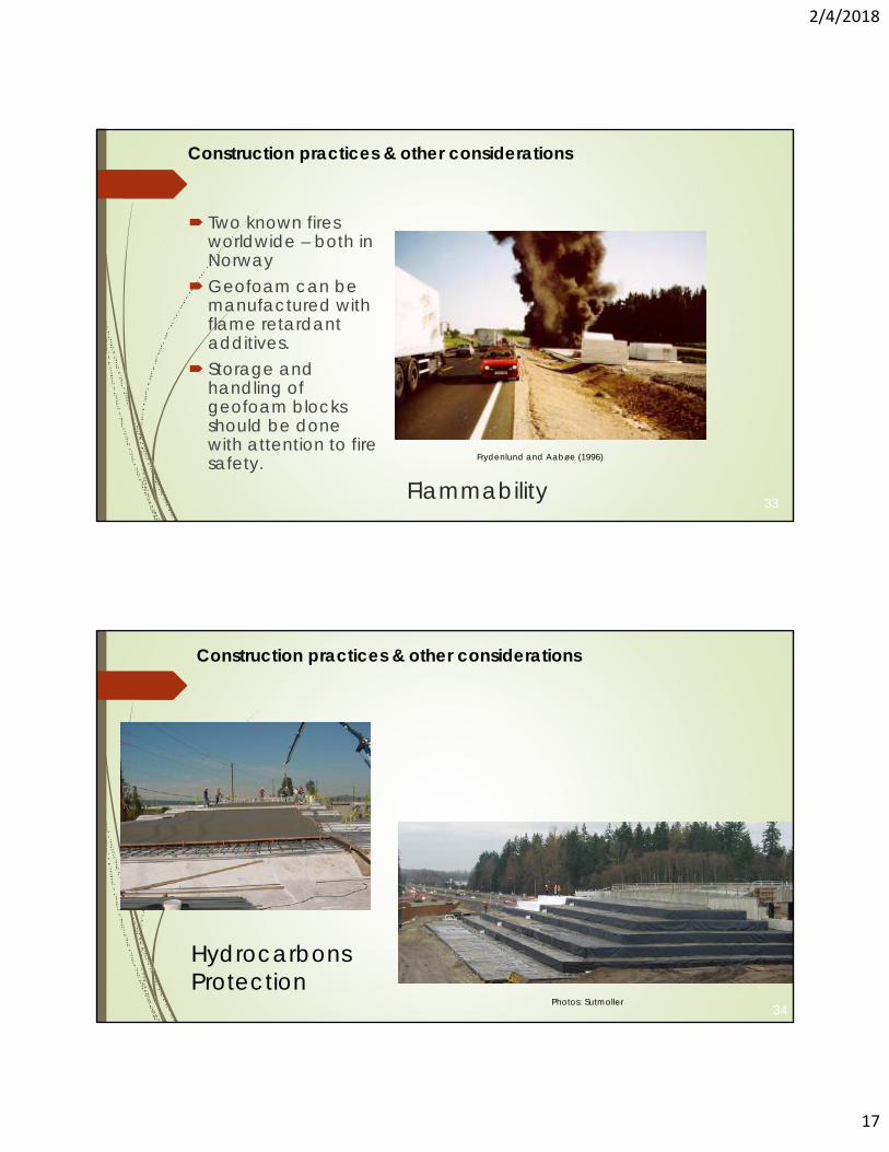
FlammabilityFrydenlund and Aabøe (1996)
Two known fires worldwide – both in Norway
Geofoam can be manufactured with flame retardant additives.
Storage and handling of geofoam blocks should be done with attention to fire safety.
33
Construction practices & other considerations
Photos: Sutmoller34
HydrocarbonsProtection
Construction practices & other considerations
2/4/2018
18
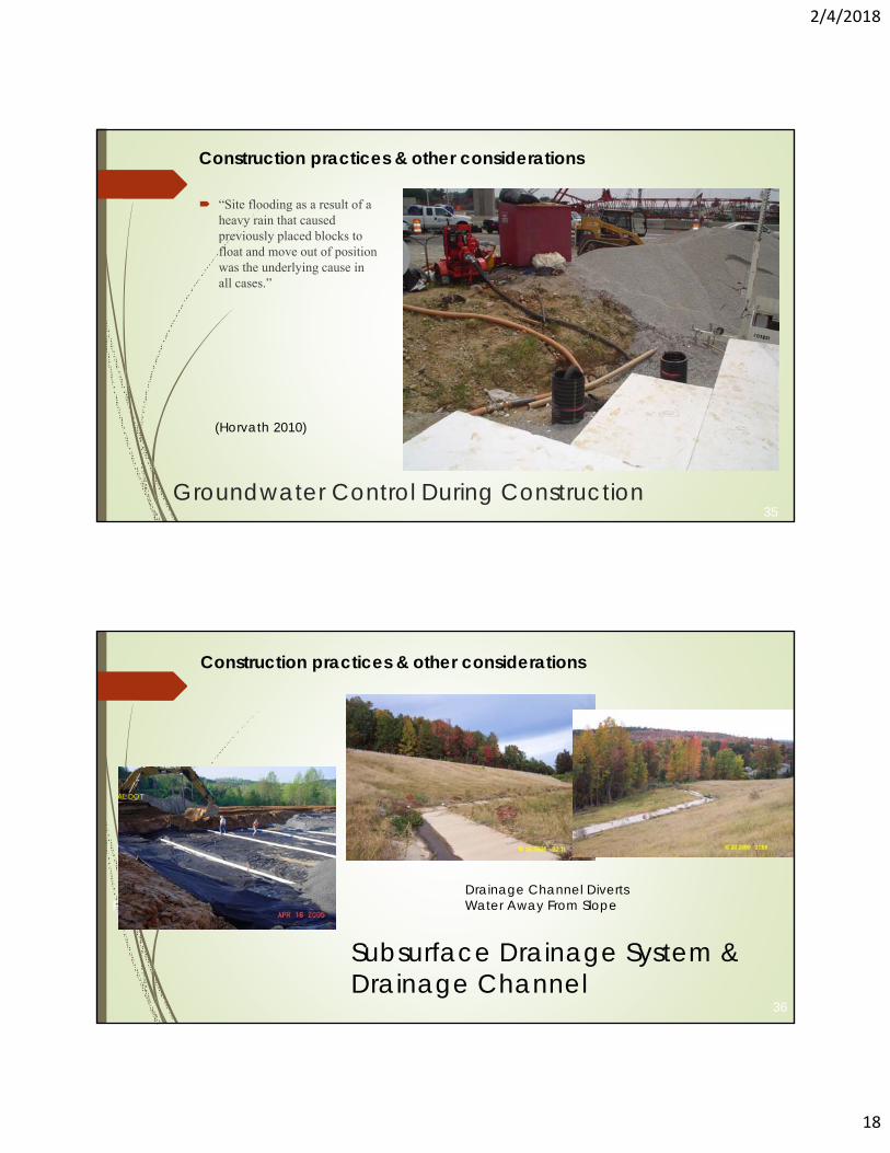
Groundwater Control During Construction
“Site flooding as a result of a heavy rain that caused previously placed blocks to float and move out of position was the underlying cause in all cases.”
(Horvath 2010)
35
Construction practices & other considerations
Placement of Subsurface Drainage
36
AL DOT
Subsurface Drainage System &Drainage Channel
Drainage Channel DivertsWater Away From Slope
Construction practices & other considerations

2/4/2018
19
Questions and Answers


![Slope Stability Guidelines for Development Applications · Slope Stability Guidelines for Development Applications [PDF 157 KB] 1.0 Introduction . The purpose of this document is](https://cdn.vdocument.in/doc/165x107/5e7ee7d8e317e76a3c6093c6/slope-stability-guidelines-for-development-applications-slope-stability-guidelines.jpg)
