www.ijcrt.org © 2021 IJCRT | Volume 9, Issue 5 May 2021 | ISSN: 2320-2882
IJCRT2105228 International Journal of Creative Research Thoughts (IJCRT) www.ijcrt.org c193
IOT BASED TRANSMISSION LINE MULTIPLE
FAULT DETECTION AND INDICATION TO EB
Mr. S. Surendiran1, D. Naveen Kumar2, S. Palraj3, S. Sankar4, K. Vignesh5
1Assistant Professor 2,3,4,5 UG Students
Electrical and Electronics Engineering
Paavai Engineering College, Tamil Nadu, India.
ABSTRACT:
The Electric Power System is divided into many different sections. One of which is the transmission
system, where power is transmitted from generating stations and substations via transmission lines into
consumers. A smart GSM based fault detection and location system was used to adequately and accurately
indicate and locate the fault had occurred. This will ensure a shorter response time for technical crew to rectify
these faults and thus help save transformers from damage and disasters. The system automatically detects faults,
analyses and classifies these faults and then, calculates the fault distance from the control room using an
impedance-based algorithm method. Finally, the fault information is transmitted to the control room. In
conclusion, the time required to locate a fault is drastically reduced, as the system automatically and accurately
provides accurate fault location information. By using this project, we can detect the faults of three phase
transmission lines one can monitor the Temperature, Voltage, Current by means of GSM modem by sending
message.
Keywords: Global System for Mobile Communication.
1. INTRODUCTION:
Power system is classified into power generation, transmission and distribution. Transmission network
is considered to be one of the vital parts of power system, as it connects the supply and the demand. The loss in
transmission and distribution network is considered to be very high, compared to other parts of power system.
Currently, the electric power infrastructure is highly vulnerable against many forms of natural and malicious
physical events, which can adversely affect the overall performance and stability of the grid. The faults in the
transmission network obstruct the supply of power to the consumer. Usually when a fault occurs in the
www.ijcrt.org © 2021 IJCRT | Volume 9, Issue 5 May 2021 | ISSN: 2320-2882
IJCRT2105228 International Journal of Creative Research Thoughts (IJCRT) www.ijcrt.org c194
transmission line it will not be seen unless it is severe. But gradually these small faults can lead to transformer
damage and destruction to human life. It can also start a fire.
At present in India, a system is not notified us the fault in real time when a fault occurs. What worrying
about is not having a real-time system, this can lead to damage to the underlying connected devices and become
a threat to the humans around us. In order to avoid such incidents to the maximum extent, maintenance or
checking of the transmission lines are generally carried out on a frequent basis. This leads to increased
manpower requirement. The fact remains that the real intention of this is not met as many a times line failure
may be due to rain, toppling of trees which cannot be predicted. Hence the transmission network fault
identification and clearance should be very fast.
To overcome these, this project is proposed an Internet of Things based Transmission Line Multiple
Fault Detection and Indication to EB. Whenever the preset threshold is crossed, the microcontroller instantly
initiates a message to be sent to the area lineman and the Control Station stating the exact pole to pole location.
This helps us to realize the real time system.
This will ensure a shorter response time for technical crew to rectify these faults and thus help save
transformers from damage and disasters. A smart GSM based fault detection and location system is used to
adequately and accurately indicate and locate where fault has occurred. The system uses a current transformer,
a voltage transformer, PIC 16F877 Microcontroller, RS-232 connector, and a GSM modem.
The system automatically detects fault, analyze and classify these faults and then, calculate the fault
distance from the control room using an impedance-based algorithm method. Finally, the fault information is
transmitted to the control room by IOT technology.
2. TRANSMISSION LINE FAULTS:
Different types of faults occurred in transmission lines are Single line-to-ground fault, Line-to-line fault,
Double Line-to-ground fault and Balance three phase fault.
Single line-to-ground fault: The most common type of faults is Single Line-to-ground faults (SLG). This type
of fault occurs when one conductor falls to the ground or gets into contacts with the neutral wire. It could also
be the result of falling trees in a rainy storm. This type could be represented.

www.ijcrt.org © 2021 IJCRT | Volume 9, Issue 5 May 2021 | ISSN: 2320-2882
IJCRT2105228 International Journal of Creative Research Thoughts (IJCRT) www.ijcrt.org c195
Figure: 1. Types of Transmission Line Faults
Line-to-line fault: The second most occurring type of faults is the Line-to-Line fault (LL). This is said to occur
when two transmission lines are short-circuited. As in the case of a large bird standing on one transmission line
and touching the other, or if a tree branch happens to fall on top of two power transmission lines.
Double Line-to-ground fault: The third type of fault is the Double Line-to-Ground fault (DLG) in figure
below. This can be a result of a tree falling on two of the power lines, or other causes.
Balance three phase fault: The fourth and the real type of fault is the balanced three phases, which can occur
by a contact between the three power lines in many different forms.
3. IMPEDANCE BASED ALGORITHM METHOD:
This Section reviews the one- and two-ended impedance-based fault location algorithms that are
commonly used to locate faults in a transmission network. The goals are to define the input data requirement of
each method and identify the different factors that affect the accuracy of location estimates.
Figure: 2. One-line Diagram of a Two-terminal Transmission Network
As the name suggests, one-ended impedance-based fault location algorithms estimate the location of a
fault by looking into a transmission line from one end as illustrated. Voltage and current waveforms captured
during a fault by an intelligent electronic device (IED) at one end of the linear used to determine the apparent
impedance between the IED device and the location of the short-circuit fault. Given the impedance of the
transmission line in ohms, the per-unit distance to a fault can be easily obtained. The advantages of using one-
ended algorithms are that they are straight forward to implement, yield reasonable location estimates, and

www.ijcrt.org © 2021 IJCRT | Volume 9, Issue 5 May 2021 | ISSN: 2320-2882
IJCRT2105228 International Journal of Creative Research Thoughts (IJCRT) www.ijcrt.org c196
require data from only one end of a line. There is no need for any communication channel or remote data and
hence, fault location can be implemented at the line terminal by any microprocessor-based numerical relay.
To illustrate the principle of one-ended methods, consider the two-terminal transmission network. The
transmission line is homogeneous and has a total positive sequence impedance of ZL1 between terminals G and
H. Networks upstream from terminals G and H are represented by their respective. Thevenin equivalents having
impedances ZG and ZH. When a fault with resistance RF occurs at a distance m per unit from terminal G, both
sources contribute to the total fault current IF. The voltage and current phasors recorded at terminal G during
the fault are VG and IG, respectively. Similarly, the voltage and current phasors recorded at terminal H during
the fault are VH and IH, respectively.
The fundamental equation that governs one- ended impedance-based fault location algorithms.
Unfortunately, because measurements from only one end of the line are used, has three unknowns, namely, m,
RF, and IF. In order to eliminate RF and IF from the fault location com- potation, several one-ended algorithms
have been developed and are discussed.
4. PROPOSED SYSTEM BLOCK DIAGRAM:
Figure: 3. Block Diagram

www.ijcrt.org © 2021 IJCRT | Volume 9, Issue 5 May 2021 | ISSN: 2320-2882
IJCRT2105228 International Journal of Creative Research Thoughts (IJCRT) www.ijcrt.org c197
Electricity is very essential to understand and monitor the behaviour of the system. We present a survey
of electric transmission line monitoring system. The goal of this project is to provide a better understanding of
the design challenges of electric distribution line monitoring system and identify important research in this
increasing important field. Proposed system used IOT (ESP8266) module and message notification send by
using GSM SIM800 module.
To attain our concepts, we need to use PIC16F877 microcontroller, Voltage Transformer, Current
Transformer, Temperature Sensor, LCD. The project is assembled with a set of resistors representing cable
length in meters and fault creation is made by a set of sensors at every known meter to cross check the accuracy
of the same. The voltage drop across the feeder resister is given to an ADC which develops a precise digital
data which the programmed microcontroller would display the same in meters. The fault occurring at what
distance and which phase is displayed on LCD interfaced with the microcontroller. If the temperature higher
than the threshold value at that time LCD will give intimation. Calculated value are sends to the internet with
the help of IOT.
The microcontroller also calculates the fault distance, relative to the device based on an impedance-
based algorithm and then relays this information to the modem for transmission. In summary, the
microcontroller classifies, calculates the fault distance and relays the information to the modem for
transmission via the serial communication interface (SCI) which serves as an interface between the
microcontroller and the modem. The RS-232 serves as the connector between the microcontroller’s serial
communication port and the modem.
The device is placed in the boundary of the sectionalised regions in the transmission system and the
location of the fault is calculated relative to the position of the device. The unique identity of the SIM card in
the GSM modem is used.
www.ijcrt.org © 2021 IJCRT | Volume 9, Issue 5 May 2021 | ISSN: 2320-2882
IJCRT2105228 International Journal of Creative Research Thoughts (IJCRT) www.ijcrt.org c198
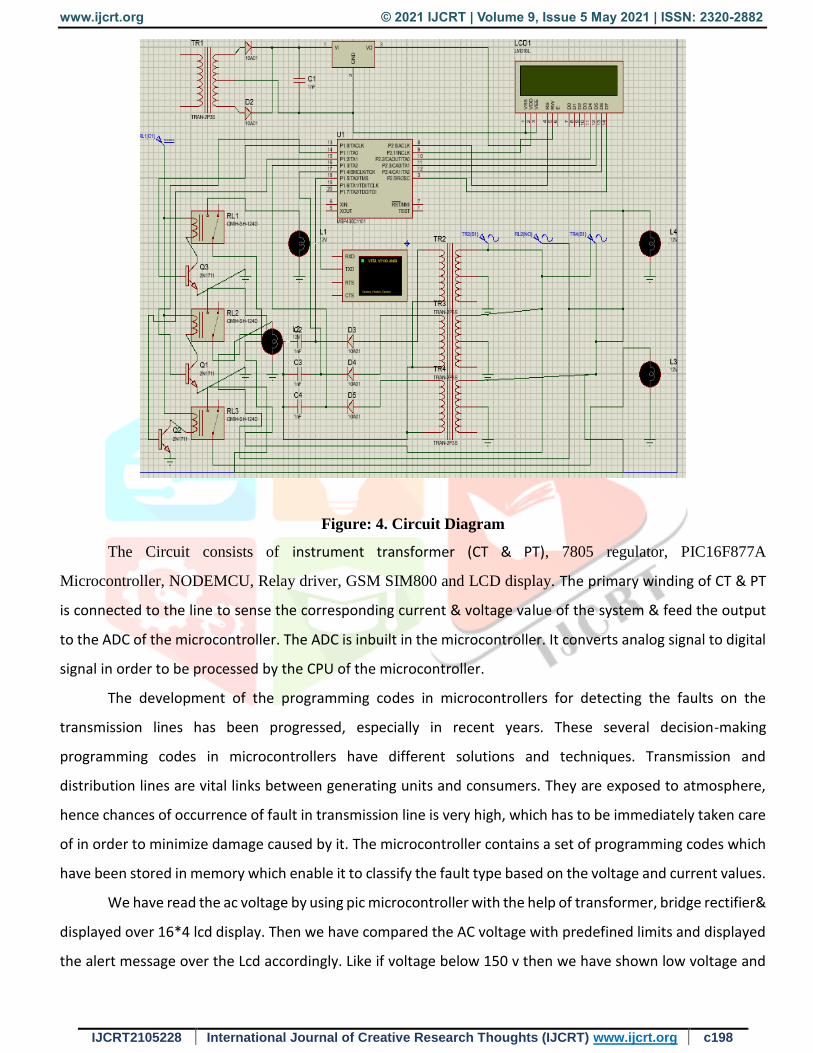
Figure: 4. Circuit Diagram
The Circuit consists of instrument transformer (CT & PT), 7805 regulator, PIC16F877A
Microcontroller, NODEMCU, Relay driver, GSM SIM800 and LCD display. The primary winding of CT & PT
is connected to the line to sense the corresponding current & voltage value of the system & feed the output
to the ADC of the microcontroller. The ADC is inbuilt in the microcontroller. It converts analog signal to digital
signal in order to be processed by the CPU of the microcontroller.
The development of the programming codes in microcontrollers for detecting the faults on the
transmission lines has been progressed, especially in recent years. These several decision-making
programming codes in microcontrollers have different solutions and techniques. Transmission and
distribution lines are vital links between generating units and consumers. They are exposed to atmosphere,
hence chances of occurrence of fault in transmission line is very high, which has to be immediately taken care
of in order to minimize damage caused by it. The microcontroller contains a set of programming codes which
have been stored in memory which enable it to classify the fault type based on the voltage and current values.
We have read the ac voltage by using pic microcontroller with the help of transformer, bridge rectifier&
displayed over 16*4 lcd display. Then we have compared the AC voltage with predefined limits and displayed
the alert message over the Lcd accordingly. Like if voltage below 150 v then we have shown low voltage and
www.ijcrt.org © 2021 IJCRT | Volume 9, Issue 5 May 2021 | ISSN: 2320-2882
IJCRT2105228 International Journal of Creative Research Thoughts (IJCRT) www.ijcrt.org c199
if voltage is above 240v then we have shown high voltage text over the lcd. We can further add a relay to
attach any ac appliances to auto cut off on low or high voltages.
5. POWER SUPPLY
A power supply (sometimes known as a power supply unit or PSU) is a device or system that supplies
electrical or other types of energy to an output load or group of loads. The term is most commonly applied to
electrical energy supplies, less often to mechanical ones, and rarely to others.
All digital circuits work only with low DC voltage. A power supply unit is required to provide the
appropriate voltage supply. This unit consists of transformer, rectifier, filter and a regulator. AC voltage
typically of 230Vrms is connected to a transformer which steps that AC voltage down to the desired AC voltage
level. A diode rectifier then provides a full wave rectified voltage that is initially filtered by a simple capacitor
filter to produce a DC voltage. This resulting DC voltage usually has some ripple or AC voltage variations.
Regulator circuit can use this DC input to provide DC voltage that not only has much less ripple voltage but
also remains in the same DC value, even when the DC voltage varies, or the load connected to the output DC
voltage changes. The required DC supply is obtained from the available AC supply after rectification, filtration
and regulation.
The main components used in the power supply unit are Transformer, Rectifier, Filter and Regulator.
The 230V AC supply is converted into 12V AC supply through the transformer. The output of the transformer
has the same frequency as in the input AC power. This AC power is converted into DC power through diodes.
Here the bridge diode is used to convert AC supply to the DC power supply. This converted DC power supply
has the ripple content and for normal operation of the circuit, the ripple content of the DC power supply should
be as low as possible. Because the ripple content of the power supply will reduce the life of the circuit. So, to
reduce the ripple content of the DC power supply, the large value of capacitance filter is used.
This filtered output will not be the regulated voltage. For this purpose, IC7805 regulator IC is used in
the circuit.
5.1 Transformer
Transformer is a device used either for stepping-up or stepping-down the AC supply voltage with a
corresponding decrease or increases in the current. Here, a transformer is used for stepping-down the voltage
so as to get a voltage that can be regulated to get a constant 5V.
5.2 Rectifier
A rectifier is a device like semiconductor, capable of converting sinusoidal input waveform units into a
unidirectional waveform, with a nonzero average component.

www.ijcrt.org © 2021 IJCRT | Volume 9, Issue 5 May 2021 | ISSN: 2320-2882
IJCRT2105228 International Journal of Creative Research Thoughts (IJCRT) www.ijcrt.org c200
5.3 Filters
Capacitors are used as filters in the power supply unit. The action of the system depends upon the fact,
that the capacitors store energy during the conduction period and delivers this energy to the load during the
inverse or non-conducting period. In this way, time during which the current passes through the load are
prolonged and ripple is considerably reduced.
5.4 Voltage Regulator
The LM78XX is three terminal regulators available with several fixed output voltages making them
useful in a wide range of applications. IC7805 is a fixed voltage regulator used in this circuit.
6. PIC16F877A MICROCONTROLLER
The PIC microcontroller PIC16F877a is one of the most renowned microcontrollers in the industry. This
microcontroller is very convenient to use, the coding or programming of this controller is also easier. One of
the main advantages is that it can be write-erase as many times as possible because it uses FLASH memory
technology. It has a total number of 40 pins and there are 33 pins for input and output. PIC16F877A is used in
many pic microcontroller projects. PIC16F877A also have much application in digital electronics circuits.
PIC16F877a finds its applications in a huge number of devices. It is used in remote sensors, security
and safety devices, home automation and many industrial instruments. An EEPROM is also featured in it which
makes it possible to store some of the information permanently like transmitter codes and receiver frequencies
and some other related data. The cost of this controller is low and its handling is also easy. It is flexible and can
be used in areas where microcontrollers have never been used before as in microprocessor applications and
timer functions etc.
7. GSM
The GSM system is the most widely used cellular technology in use in the world today. It has been a
particularly successful cellular phone technology for a variety of reasons including the ability to roam
worldwide with the certainty of being able to be able to operate on GSM networks in exactly the same way -
provided billing agreements are in place.
The letters GSM originally stood for the words Groupe Special Mobile, but as it became clear this
cellular technology was being used worldwide the meaning of GSM was changed to Global System for Mobile
Communications. Since this cellular technology was first deployed in 1991, the use of GSM has grown steadily,
and it is now the most widely cell phone system in the world. GSM reached the 1 billion subscriber point in
February 2004, and is now well over the 3 billion subscriber mark and still steadily increasing.
www.ijcrt.org © 2021 IJCRT | Volume 9, Issue 5 May 2021 | ISSN: 2320-2882
IJCRT2105228 International Journal of Creative Research Thoughts (IJCRT) www.ijcrt.org c201
7.1 GSM Services
Speech or voice calls are obviously the primary function for the GSM cellular system. To achieve this
the speech is digitally encoded and later decoded using a vocoder. A variety of vocoders are available for use,
being aimed at different scenarios.
In addition to the voice services, GSM cellular technology supports a variety of other data services.
Although their performance is nowhere near the level of those provided by 3G, they are nevertheless still
important and useful. A variety of data services are supported with user data rates up to 9.6 kbps. Services
including Group 3 facsimile, videotext and teletex can be supported.
One service that has grown enormously is the short message service. Developed as part of the GSM
specification, it has also been incorporated into other cellular technologies. It can be thought of as being similar
to the paging service but is far more comprehensive allowing bi-directional messaging, store and forward
delivery, and it also allows alphanumeric messages of a reasonable length. This service has become particularly
popular, initially with the young as it provided a simple, low fixed cost.
8. NODE MCU
Node MCU is an open source IoT platform. Which includes firmware which runs on the ESP8266 Wi-
Fi Module from Expressive Systems, and hardware which is based on the ESP-12 module. The term “Node
MCU” by default refers to the firmware rather than the dev kits. Node MCU firmware was developed so that
AT commands can be replaced with Lua scripting making the life of developers easier. So, it would be redundant
to use AT commands again in Node MCU.
8.1 ESP8266 Feature
Open-source
Interactive
Programmable
Low cost
Simple
Smart
WI-FI enabled
USB-TTL included
Plug & Play

www.ijcrt.org © 2021 IJCRT | Volume 9, Issue 5 May 2021 | ISSN: 2320-2882
IJCRT2105228 International Journal of Creative Research Thoughts (IJCRT) www.ijcrt.org c202
Figure: 5. NODE MCU
Advantages
System cost is low compared to SCADA.
We can see the data through online communication.
Large number data aggregation.
Predictive analysis.
Time saving.
Applications
Power grid primary distribution.
High voltage transmission line.
Micro grid.

www.ijcrt.org © 2021 IJCRT | Volume 9, Issue 5 May 2021 | ISSN: 2320-2882
IJCRT2105228 International Journal of Creative Research Thoughts (IJCRT) www.ijcrt.org c203
9. RESULT AND PHOTO KIT:
www.ijcrt.org © 2021 IJCRT | Volume 9, Issue 5 May 2021 | ISSN: 2320-2882
IJCRT2105228 International Journal of Creative Research Thoughts (IJCRT) www.ijcrt.org c204
10. CONCLUSION:
The proposed project inherits all drawbacks of the existing system. Here, in this project we have
designed a GSM based transmission line monitoring and indication system that sends information of the same
to control room via SMS. The implemented system design mainly concentrates on the distribution system. It
provides the way to detect the faults such as wastage of energy and power theft.
The system continuously monitors various parameters of the system. It also helps to detect the fault at
the appropriate time and hence avoids illegal use of electricity. Automatic monitoring, analyzing and recording
is done on the PC screen through hyper terminal. The project has continuous monitoring system integrating the
GSM communication technology and the microcontroller technology. It also represents the hardware
architecture and the software flow.
The implementation of the system will save large amount of electricity and thereby electricity will be
available for a greater number of consumers in a highly populated country such as India.
11. FUTURE SCOPE:
In future, this project will enhance the fault detection in underground cables using Raspberry PI.
It helps to detect which type of fault occurred and exact location of fault also.
12. REFERENCE:
1. Chandra shekar. P “Transmission Line Fault Detection & Indication through GSM" ISNN(Online): 2347
- 2812, Volume-2, Issue – 5, 2014.
2. Hui Hwang Goh, Sy yi Sim, Asad Shaykh, Md,Humayun Kabir, Chin Wan Ling, Qing Shi Chua, Kai
Chen Goh "Transmission Line Fault Detection" ISNN: 2502 – 4752, Volume-8, DOI:
10.11591/ijeecs.v8.i1.pp199-205, 2017.
3. Arti Sanganwar, Kapil Chalkhure, Shivani Jijankar, Anand Dhore, Prof. Vikramsingh R.Parihar
"Transmission Line Multiple Fault Detection" ISSN: 2393 - 8374, (Online): 2394 - 0697, Volume-4,
Issue - 10, 2017.
4. Navaneetha Krishna.R, Niranjan.L, Shyamsundar.N, Dr. C.Venkatesan "IoT Based Transmisson Line
Fault Monitoring System" IJRAR August 2020, Volume-7, Issue - 3, E- ISSN 2348 - 1269, P- ISSN
2349 - 5138, 2020.
5. Swagata Das, Surya Santoso, Anish Gaikwad, Mahendra Patel "Impedance Based Fault Location in
Transmission Networks” DOI: 10.1109/ACCESS.2014.2323353, Volume – 2, 2014.


