Download - KEOR COMPACT JBUS / MODBUS Protocol

LE12722AA – 20/12
The copying, redistribution, use or publication of such contents is strictly prohibited without Legrand authorization
KEOR COMPACT
JBUS / MODBUS Protocol
Table of Contents
1. Introduction ....................................................................................................... 1
1.1 Communication Layers ...................................................................... 1
2. JBUS General Purpose....................................................................................... 1
2.1 General Message Format .................................................................... 1
2.2 JBUS/MODBUS protocol .................................................................. 2
2.3 Data decoding .................................................................................... 2
2.4 Acknowledgement of end of data package .......................................... 2
3. Definition of the JBUS/MODBUS protocol ....................................................... 3
3.1 General data structure ......................................................................... 3
4. JBUS interface in Unit system configuratio ....................................................... 4
4.1 General data area ................................................................................ 4
4.2 UPS Status data area .......................................................................... 4
4.3 UPS Alarms data area ......................................................................... 9
4.4 UPS Measurement area .................................................................... 13
4.5 UPS Control area ............................................................................. 16
4.6 UPS Configurations area .................................................................. 17
5. JBUS interface in parallel system configuration ............................................... 18
5.1 General data area .............................................................................. 18
5.2 SYS Status data area ........................................................................ 19
5.3 SYS Alarm data area ........................................................................ 23
5.4 SYS Measurement data area ............................................................. 28
5.5 SYS Control area ............................................................................. 31
5.6 SYS Configurations area .................................................................. 32

KEOR COMPACT
1
1. Introduction
This document describes the KEOR COMPACT Series UPS protocol, adopted to communicate with all
communication products, like Supervisor, Network communication, etc...
This protocol will be implemented in the KEOR COMPACT Series UPS equipment, in order to use the
same driver for all products.
1.1 Communication Layers
2. JBUS General Purpose
JBUS/MODBUS is a Master/Slave protocol, in which Master could be one of the 255 slaves. The master
sent a request to a slaver; the slaver sent the data or an ACK to the Master.
2.1 General Message Format
➢ The JBUS/MODBUS protocol includes various functions that are intended for collecting
information in different ways. As follows:
Function (03h) for reading registers.
Function (06h) for 1 word writing registers.
Remark: 1 Address = 16 bits or 1 Word (LSB and MSB)
APPLICATIONS
REMOTE MONITOR
TERMINAL CENTRAL COMPUTER
DATA TABLE
FIXED
ADDRESS SPECIFICATION
PUBLIC DATA
JBUS/MODBUS in RTU mode
MODBUS TRANSPORT PROTOCOL
HARDWARE
RS485
SLAVE NUMBER (1 byte) Specified the destination node
FUNCTION CODE (1 byte) Specified a READ or WRITE data command
DATA FIELD Information to read or write data
(Address, value, number of data...)
CONTROL WORD (CRC16) (2 bytes, 1 word) Algorithm calculation of each data

KEOR COMPACT
2
2.2 JBUS/MODBUS protocol
2.2.1 Function description
✓ Function 0x03
Master request: 8 bytes
Slave
Number
Function
READ
Address
High
Address
Low
0 Nb of word
to read
CRC
Low
CRC
High
1 0x03 0xE0 0x00 0 10
Ex. Request to slave number1, the data (10 words) beginning at 0xE000 (Address)
Slave Message:
Slave
Number
Function
READ
Nb of
byte
First data
hi byte
First data
low byte
Next data CRC
Low
CRC
High
1 0x03 20 0x20 0x02 ……
Example: the first data is (0x20 * 256) + 0x02=0x2002
✓ FUNCTION 0x06
This function is used to send a command to the slave.
Slave
Number
Function
WRITE
Address
High
Address
Low
data to
write
high byte
data to
write
low byte
CRC
Low
CRC
High
1 0x06 0xE0 0x10 0x30 0x03
Slave message:
Slave
Number
Function
WRITE
Address
High
Address
Low
data to
write
high byte
data to
write
low byte
CRC
Low
CRC
High
1 0x06 0xE0 0x10 0x30 0x03
The slave sends the same message if not error occurred.
2.3 Data decoding
➢ Status and alarms Information
The information are coding in bit. This means that 1 word defines 16 information.
➢ Measurements data
1 word defines a measurement. Some values are numeric decimal signed or unsigned (0 to
65535 or from -32767 to 32767).
2.4 Acknowledgement of end of data package
A time-out equal to a value of 10* time of transmission of a character, points out that the data
package is finished (the CRC has been sent).
2.4.1 CRC 16 CALCULATION

KEOR COMPACT
3
2.4.2 Example of CRC calculation
unsigned int CALCUL_CRC(unsigned int *Msg) {
unsigned int Crc; int lenght,i,n; Crc = 0xFFFF; lenght = Msg[0]; for ( i = 1 ; i <= lenght ; i++ ) { Crc ^= Msg[i]; for ( n = 1 ; n <= 8 ; n++) { /* if CRC is even */ if ((Crc % 2) == 0) /* to right decrement */ Crc >>= 1; else { Crc >>= 1; Crc ^= 0xA001; } } } return( Crc );
}
3. Definition of the JBUS/MODBUS protocol
3.1 General data structure
JBUS/MODBUS-table
Index Table JBUS/MODBUS Function
1 Status 03h READ
2 Alarms 03h READ

KEOR COMPACT
4
3 Measurement 03h READ
4 Control 06h WRITE
5 Configurations 03h READ
➢ Incoming data structure
Example of 4 words
1 2 3 4 5 6 7 8
MSB0 LSB0 MSB0 LSB0 MSB0 LSB0 MSB0 LSB0
Bit15 Bit0 Bit15 Bit0 Bit15 Bit0 Bit15 Bit0
WORD0 WORD1 WORD2 WORD3
Status15 Status0 Status31 Status16 Status47 Status32 Status63 Status48
Alarm15 Alarm0 Alarm31 Alarm16 Alarm47 Alarm32 Alarm63 Alarm48
M00 M01 M02 M03
4. JBUS interface in Unit system configuratio
4.1 General data area
Index Table Start
addresses
Table length in words JBUS/MODBUS Function
1 UPS Status 0xn000 8 03h READ
2 UPS Alarms 0xn010 10 03h READ
3 UPS Measurement 0xn030 97 03h READ
4 UPS Control 0xn0D0 1 06h WRITE
5 UPS Configurations 0xn1EC 2 03h READ
Remark: n = (number of unit ID + 1).
Remark: The UPS Information table should be read word by word or per group, without exceed the
length of the table.
4.2 UPS Status data area
STATUS : Address from 0xn000, 10 WORDS
Code Description BIT Address
S00 Rectifier Input Present OK 0 0xn000
S01 Bypass Input Present OK 1 0xn000
S02 RESERVED 2 0xn000
S03 RESERVED 3 0xn000
S04 RESERVED 4 0xn000
S05 UPS in Normal Mode 5 0xn000
S06 RESERVED 6 0xn000

KEOR COMPACT
5
S07 UPS in ECO Mode 7 0xn000
S08 UPS in Converter Mode 8 0xn000
S09 RESERVED 9 0xn000
S10 RESERVED 10 0xn000
S11 RESERVED 11 0xn000
S12 RESERVED 12 0xn000
S13 RESERVED 13 0xn000
S14 Rectifier on 14 0xn000
S15 Inverter on 15 0xn000
S16 Battery Discharger on 0 0xn001
S17 Battery Charger on 1 0xn001
S18 RESERVED 2 0xn001
S19 RESERVED 3 0xn001
S20 RESERVED 4 0xn001
S21 Load off 5 0xn001
S22 Load on Inverter 6 0xn001
S23 Load on Bypass 7 0xn001
S24 Load on Manual bypass 8 0xn001
S25 Permission for ECO mode aux supply 9 0xn001
S26 RESERVED 10 0xn001
S27 RESERVED 11 0xn001
S28 RESERVED 12 0xn001
S29 RESERVED 13 0xn001
S30 Inverter Sync. With Bypass 14 0xn001
S31 RESERVED 15 0xn001
S32 RESERVED 0 0xn002
S33 Unitary Operation 1 0xn002
S34 Parallel Operation 2 0xn002
S35 Redundancy Operation 3 0xn002
S36 RESERVED 4 0xn002
S37 RESERVED 5 0xn002
S38 RESERVED 6 0xn002
S39 RESERVED 7 0xn002
S40 Vbatt. Ok 8 0xn002
S41 Vbatt. Low 9 0xn002
S42 Vbatt. Min 10 0xn002
S43 ESS Discharging 11 0xn002
S44 ESS Schedule Set 12 0xn002
KEOR COMPACT
6
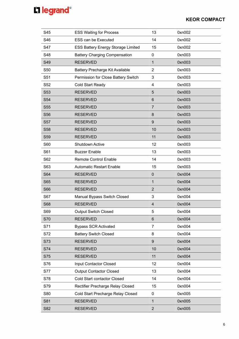
S45 ESS Waiting for Process 13 0xn002
S46 ESS can be Executed 14 0xn002
S47 ESS Battery Energy Storage Limited 15 0xn002
S48 Battery Charging Compensation 0 0xn003
S49 RESERVED 1 0xn003
S50 Battery Precharge Kit Available 2 0xn003
S51 Permission for Close Battery Switch 3 0xn003
S52 Cold Start Ready 4 0xn003
S53 RESERVED 5 0xn003
S54 RESERVED 6 0xn003
S55 RESERVED 7 0xn003
S56 RESERVED 8 0xn003
S57 RESERVED 9 0xn003
S58 RESERVED 10 0xn003
S59 RESERVED 11 0xn003
S60 Shutdown Active 12 0xn003
S61 Buzzer Enable 13 0xn003
S62 Remote Control Enable 14 0xn003
S63 Automatic Restart Enable 15 0xn003
S64 RESERVED 0 0xn004
S65 RESERVED 1 0xn004
S66 RESERVED 2 0xn004
S67 Manual Bypass Switch Closed 3 0xn004
S68 RESERVED 4 0xn004
S69 Output Switch Closed 5 0xn004
S70 RESERVED 6 0xn004
S71 Bypass SCR Activated 7 0xn004
S72 Battery Switch Closed 8 0xn004
S73 RESERVED 9 0xn004
S74 RESERVED 10 0xn004
S75 RESERVED 11 0xn004
S76 Input Contactor Closed 12 0xn004
S77 Output Contactor Closed 13 0xn004
S78 Cold Start contactor Closed 14 0xn004
S79 Rectifier Precharge Relay Closed 15 0xn004
S80 Cold Start Precharge Relay Closed 0 0xn005
S81 RESERVED 1 0xn005
S82 RESERVED 2 0xn005

KEOR COMPACT
7
S83 RESERVED 3 0xn005
S84 Unit is Master 4 0xn005
S85 Unit is Slave 5 0xn005
S86 RESERVED 6 0xn005
S87 RESERVED 7 0xn005
S88 RESERVED 8 0xn005
S89 RESERVED 9 0xn005
S90 RESERVED 10 0xn005
S91 RESERVED 11 0xn005
S92 RESERVED 12 0xn005
S93 RESERVED 13 0xn005
S94 RESERVED 14 0xn005
S95 RESERVED 15 0xn005
S96 RESERVED 0 0xn006
S97 RESERVED 1 0xn006
S98 RESERVED 2 0xn006
S99 RESERVED 3 0xn006
S100 RESERVED 4 0xn006
S101 RESERVED 5 0xn006
S102 RESERVED 6 0xn006
S103 RESERVED 7 0xn006
S104 RESERVED 8 0xn006
S105 RESERVED 9 0xn006
S106 RESERVED 10 0xn006
S107 RESERVED 11 0xn006
S108 RESERVED 12 0xn006
S109 RESERVED 13 0xn006
S110 Slot1 Relay Card Present(1) 14 0xn006
S111 Slot2 Relay Card Present(1) 15 0xn006
S112 Slot1 Output Relay 1 Activated(1) 0 0xn007
S113 Slot1 Output Relay 2 Activated (1) 1 0xn007
S114 Slot1 Output Relay 3 Activated (1) 2 0xn007
S115 Slot1 Output Relay 4 Activated (1) 3 0xn007
S116 Slot1 Output Relay 5 Activated (1) 4 0xn007
S117 Slot1 Output Relay 6 Activated (1) 5 0xn007
S118 Slot2 Output Relay 1 Activated(1) 6 0xn007
S119 Slot2 Output Relay 2 Activated (1) 7 0xn007
S120 Slot2 Output Relay 3 Activated (1) 8 0xn007

KEOR COMPACT
8
S121 Slot2 Output Relay 4 Activated (1) 9 0xn007
S122 Slot2 Output Relay 5 Activated (1) 10 0xn007
S123 Slot2 Output Relay 6 Activated (1) 11 0xn007
S124 RESERVED 12 0xn007
S125 RESERVED 13 0xn007
S126 RESERVED 14 0xn007
S127 RESERVED 15 0xn007
S128 RESERVED 0 0xn008
S129 RESERVED 1 0xn008
S130 RESERVED 2 0xn008
S131 RESERVED 3 0xn008
S132 RESERVED 4 0xn008
S133 RESERVED 5 0xn008
S134 RESERVED 6 0xn008
S135 RESERVED 7 0xn008
S136 RESERVED 8 0xn008
S137 RESERVED 9 0xn008
S138 RESERVED 10 0xn008
S139 RESERVED 11 0xn008
S140 RESERVED 12 0xn008
S141 RESERVED 13 0xn008
S142 RESERVED 14 0xn008
S143 RESERVED 15 0xn008
S144 Schedule Battery Test Process
Permitted
0 0xn009
S145 Manual Battery Test Process Permitted 1 0xn009
S146 After Battery Test, Battery is Aging 2 0xn009
S147 After Battery Test, Battery Pass 3 0xn009
S148 Battery Test Fail 4 0xn009
S149 Battery Test in Progress 5 0xn009
S150 Battery Test Condition Incompatible 6 0xn009
S151 Waiting for The Battery Test Process 7 0xn009
S152 Manual Battery Test Time is Limited in 2
Minutes
8 0xn009
S153 RESERVED 9 0xn009
S154 RESERVED 10 0xn009
S155 RESERVED 11 0xn009
S156 Energy Saver Enable 12 0xn009

KEOR COMPACT
9
S157 Energy Saver On 13 0xn009
S158 Energy Saver is Operating 14 0xn009
S159 Unit is Standing by 15 0xn009
Note. Status with “RESERVED” are not usable in KEOR COMPACT Series protocol.
(1) Optional function for Relay Card.
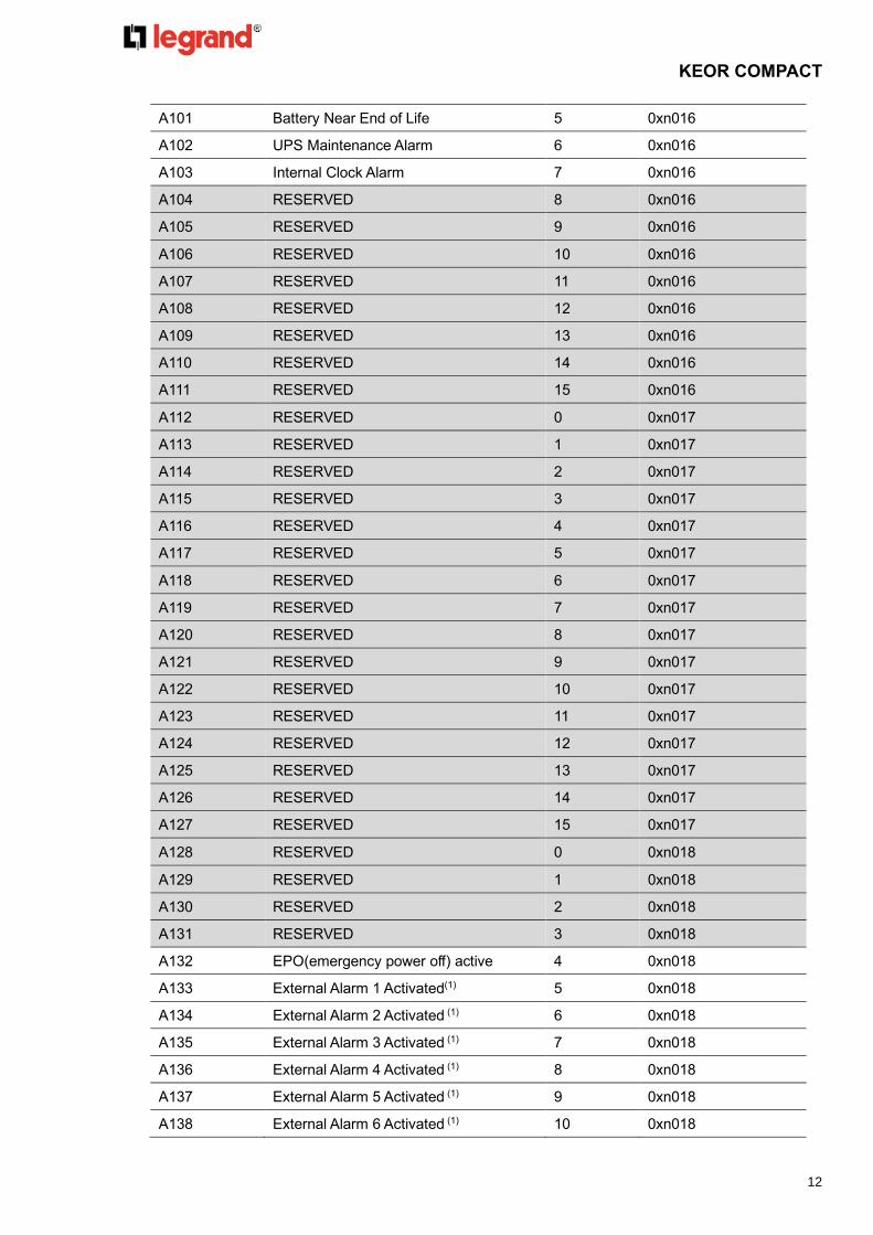
4.3 UPS Alarms data area
ALARMS : Address from 0xn010, 10 WORDS
Code Description BIT Address
A00 RESERVED 0 0xn010
A01 General Alarm 1 0xn010
A02 Inverter General Alarm 2 0xn010
A03 Mains General Alarm 3 0xn010
A04 Discharger General Alarm 4 0xn010
A05 Charger General Alarm 5 0xn010
A06 Bypass General Alarm 6 0xn010
A07 RESERVED 7 0xn010
A08 RESERVED 8 0xn010
A09 RESERVED 9 0xn010
A10 Over Temp. 10 0xn010
A11 RESERVED 11 0xn010
A12 RESERVED 12 0xn010
A13 RESERVED 13 0xn010
A14 Interior over Temp. 14 0xn010
A15 Battery Room over Temp. 15 0xn010
A16 Converter Stop Due To UPS Overheat 0 0xn011
A17 RESERVED 1 0xn011
A18 RESERVED 2 0xn011
A19 RESERVED 3 0xn011
A20 RESERVED 4 0xn011
A21 RESERVED 5 0xn011
A22 RESERVED 6 0xn011
A23 RESERVED 7 0xn011
A24 RESERVED 8 0xn011
A25 Inverter Fault 9 0xn011
A26 Rectifier Fault 10 0xn011
A27 Discharger Fault 11 0xn011
A28 Charger Fault 12 0xn011
KEOR COMPACT
10
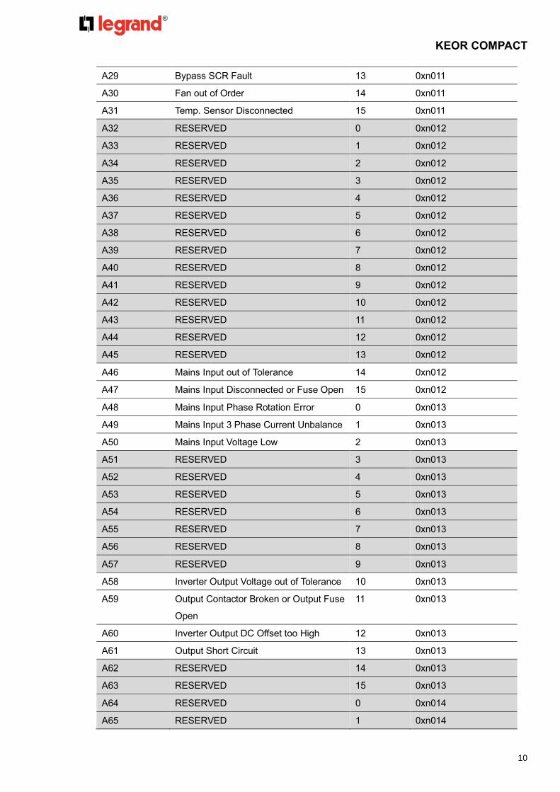
A29 Bypass SCR Fault 13 0xn011
A30 Fan out of Order 14 0xn011
A31 Temp. Sensor Disconnected 15 0xn011
A32 RESERVED 0 0xn012
A33 RESERVED 1 0xn012
A34 RESERVED 2 0xn012
A35 RESERVED 3 0xn012
A36 RESERVED 4 0xn012
A37 RESERVED 5 0xn012
A38 RESERVED 6 0xn012
A39 RESERVED 7 0xn012
A40 RESERVED 8 0xn012
A41 RESERVED 9 0xn012
A42 RESERVED 10 0xn012
A43 RESERVED 11 0xn012
A44 RESERVED 12 0xn012
A45 RESERVED 13 0xn012
A46 Mains Input out of Tolerance 14 0xn012
A47 Mains Input Disconnected or Fuse Open 15 0xn012
A48 Mains Input Phase Rotation Error 0 0xn013
A49 Mains Input 3 Phase Current Unbalance 1 0xn013
A50 Mains Input Voltage Low 2 0xn013
A51 RESERVED 3 0xn013
A52 RESERVED 4 0xn013
A53 RESERVED 5 0xn013
A54 RESERVED 6 0xn013
A55 RESERVED 7 0xn013
A56 RESERVED 8 0xn013
A57 RESERVED 9 0xn013
A58 Inverter Output Voltage out of Tolerance 10 0xn013
A59 Output Contactor Broken or Output Fuse
Open
11 0xn013
A60 Inverter Output DC Offset too High 12 0xn013
A61 Output Short Circuit 13 0xn013
A62 RESERVED 14 0xn013
A63 RESERVED 15 0xn013
A64 RESERVED 0 0xn014
A65 RESERVED 1 0xn014
KEOR COMPACT
11
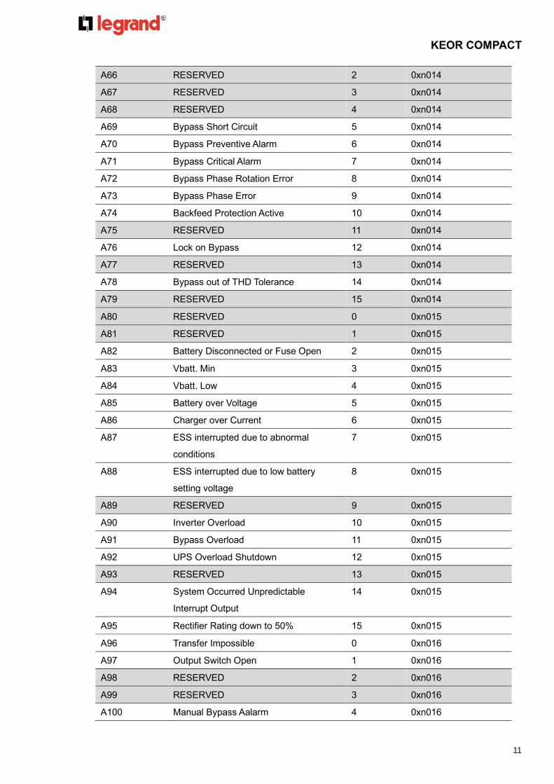
A66 RESERVED 2 0xn014
A67 RESERVED 3 0xn014
A68 RESERVED 4 0xn014
A69 Bypass Short Circuit 5 0xn014
A70 Bypass Preventive Alarm 6 0xn014
A71 Bypass Critical Alarm 7 0xn014
A72 Bypass Phase Rotation Error 8 0xn014
A73 Bypass Phase Error 9 0xn014
A74 Backfeed Protection Active 10 0xn014
A75 RESERVED 11 0xn014
A76 Lock on Bypass 12 0xn014
A77 RESERVED 13 0xn014
A78 Bypass out of THD Tolerance 14 0xn014
A79 RESERVED 15 0xn014
A80 RESERVED 0 0xn015
A81 RESERVED 1 0xn015
A82 Battery Disconnected or Fuse Open 2 0xn015
A83 Vbatt. Min 3 0xn015
A84 Vbatt. Low 4 0xn015
A85 Battery over Voltage 5 0xn015
A86 Charger over Current 6 0xn015
A87 ESS interrupted due to abnormal
conditions
7 0xn015
A88 ESS interrupted due to low battery
setting voltage
8 0xn015
A89 RESERVED 9 0xn015
A90 Inverter Overload 10 0xn015
A91 Bypass Overload 11 0xn015
A92 UPS Overload Shutdown 12 0xn015
A93 RESERVED 13 0xn015
A94 System Occurred Unpredictable
Interrupt Output
14 0xn015
A95 Rectifier Rating down to 50% 15 0xn015
A96 Transfer Impossible 0 0xn016
A97 Output Switch Open 1 0xn016
A98 RESERVED 2 0xn016
A99 RESERVED 3 0xn016
A100 Manual Bypass Aalarm 4 0xn016
KEOR COMPACT
12
A101 Battery Near End of Life 5 0xn016
A102 UPS Maintenance Alarm 6 0xn016
A103 Internal Clock Alarm 7 0xn016
A104 RESERVED 8 0xn016
A105 RESERVED 9 0xn016
A106 RESERVED 10 0xn016
A107 RESERVED 11 0xn016
A108 RESERVED 12 0xn016
A109 RESERVED 13 0xn016
A110 RESERVED 14 0xn016
A111 RESERVED 15 0xn016
A112 RESERVED 0 0xn017
A113 RESERVED 1 0xn017
A114 RESERVED 2 0xn017
A115 RESERVED 3 0xn017
A116 RESERVED 4 0xn017
A117 RESERVED 5 0xn017
A118 RESERVED 6 0xn017
A119 RESERVED 7 0xn017
A120 RESERVED 8 0xn017
A121 RESERVED 9 0xn017
A122 RESERVED 10 0xn017
A123 RESERVED 11 0xn017
A124 RESERVED 12 0xn017
A125 RESERVED 13 0xn017
A126 RESERVED 14 0xn017
A127 RESERVED 15 0xn017
A128 RESERVED 0 0xn018
A129 RESERVED 1 0xn018
A130 RESERVED 2 0xn018
A131 RESERVED 3 0xn018
A132 EPO(emergency power off) active 4 0xn018
A133 External Alarm 1 Activated(1) 5 0xn018
A134 External Alarm 2 Activated (1) 6 0xn018
A135 External Alarm 3 Activated (1) 7 0xn018
A136 External Alarm 4 Activated (1) 8 0xn018
A137 External Alarm 5 Activated (1) 9 0xn018
A138 External Alarm 6 Activated (1) 10 0xn018

KEOR COMPACT
13
A139 External Alarm 7 Activated (1) 11 0xn018
A140 External Alarm 8 Activated (1) 12 0xn018
A141 External Alarm 9 Activated (1) 13 0xn018
A142 External Alarm 10 Activated (1) 14 0xn018
A143 External Alarm 11 Activated (1) 15 0xn018
A144 External Alarm 12 Activated (1) 0 0xn019
A145 RESERVED 1 0xn019
A146 RESERVED 2 0xn019
A147 RESERVED 3 0xn019
A148 RESERVED 4 0xn019
A149 RESERVED 5 0xn019
A150 RESERVED 6 0xn019
A151 RESERVED 7 0xn019
A152 RESERVED 8 0xn019
A153 RESERVED 9 0xn019
A154 RESERVED 10 0xn019
A155 RESERVED 11 0xn019
A156 RESERVED 12 0xn019
A157 RESERVED 13 0xn019
A158 RESERVED 14 0xn019
A159 RESERVED 15 0xn019
Note. Status with “RESERVED” are not usable in KEOR COMPACT Series protocol.
(1) Optional function for Relay Card.
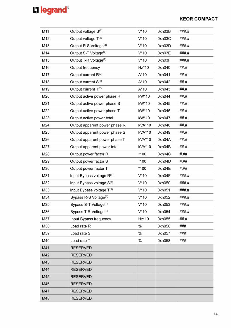
4.4 UPS Measurement area
Information : Address from 0xn030, 121 WORDS
Code Description Unit Address Data Format
M00 Input voltage R(1) V*10 0xn030 ###.#
M01 Input voltage S(1) V*10 0xn031 ###.#
M02 Input voltage T(1) V*10 0xn032 ###.#
M03 Input R-S Voltage(1) V*10 0xn033 ###.#
M04 Input S-T Voltage(1) V*10 0xn034 ###.#
M05 Input T-R Voltage(1) V*10 0xn035 ###.#
M06 Input frequency Hz*10 0xn036 ##.#
M07 Input current R(1) A*10 0xn037 ###.#
M08 Input current S(1) A*10 0xn038 ###.#
M09 Input current T(1) A*10 0xn039 ###.#
M10 Output voltage R(2) V*10 0xn03A ###.#
KEOR COMPACT
14
M11 Output voltage S(2) V*10 0xn03B ###.#
M12 Output voltage T(2) V*10 0xn03C ###.#
M13 Output R-S Voltage(2) V*10 0xn03D ###.#
M14 Output S-T Voltage(2) V*10 0xn03E ###.#
M15 Output T-R Voltage(2) V*10 0xn03F ###.#
M16 Output frequency Hz*10 0xn040 ##.#
M17 Output current R(2) A*10 0xn041 ##.#
M18 Output current S(2) A*10 0xn042 ##.#
M19 Output current T(2) A*10 0xn043 ##.#
M20 Output active power phase R kW*10 0xn044 ##.#
M21 Output active power phase S kW*10 0xn045 ##.#
M22 Output active power phase T kW*10 0xn046 ##.#
M23 Output active power total kW*10 0xn047 ##.#
M24 Output apparent power phase R kVA*10 0xn048 ##.#
M25 Output apparent power phase S kVA*10 0xn049 ##.#
M26 Output apparent power phase T kVA*10 0xn04A ##.#
M27 Output apparent power total kVA*10 0xn04B ##.#
M28 Output power factor R *100 0xn04C #.##
M29 Output power factor S *100 0xn04D #.##
M30 Output power factor T *100 0xn04E #.##
M31 Input Bypass voltage R(1) V*10 0xn04F ###.#
M32 Input Bypass voltage S(1) V*10 0xn050 ###.#
M33 Input Bypass voltage T(1) V*10 0xn051 ###.#
M34 Bypass R-S Voltage(1) V*10 0xn052 ###.#
M35 Bypass S-T Voltage(1) V*10 0xn053 ###.#
M36 Bypass T-R Voltage(1) V*10 0xn054 ###.#
M37 Input Bypass frequency Hz*10 0xn055 ##.#
M38 Load rate R % 0xn056 ###
M39 Load rate S % 0xn057 ###
M40 Load rate T % 0xn058 ###
M41 RESERVED
M42 RESERVED
M43 RESERVED
M44 RESERVED
M45 RESERVED
M46 RESERVED
M47 RESERVED
M48 RESERVED

KEOR COMPACT
15
M49 RESERVED
M50~M54 RESERVED
M55 Inverter overload counter 0xn068 #####
M56 Bypass overload counter 0xn069 #####
M57 RESERVED
M58 RESERVED
M59 RESERVED
M60 RESERVED
M61 RESERVED
M62 RESERVED
M63 RESERVED
M64 Battery remaining capacity %*10 0xn070 ##.#
M65 RESERVED
M66 Remaining run time Min*1 0xn072 ###
M67 Positive total battery voltage V*100 0xn073 ###.##
M68 Negative total battery voltage V*100 0xn074 ###.##
M69 Positive battery voltage per cell V*100 0xn075 #.##
M70 Negative battery voltage per cell V*100 0xn076 #.##
M71 Charging watt kW*100 0xn077 ###.##
M72 Discharging watt kW*100 0xn078 ###.##
M73 Positive battery charger current A*100 0xn079 ###.##
M74 Negative battery charger current A*100 0xn07A ###.##
M75 Positive battery discharger current A*100 0xn07B ###.##
M76 Negative battery discharger current A*100 0xn07C ###.##
M77 RESERVED
M78 RESERVED
M79 RESERVED
M80 Rectifier T1 temperature ℃*10(3) 0xn080 ##.#
M81 RESERVED ℃*10(3) 0xn081 ##.#
M82 Rectifier T2 temperature ℃*10(3) 0xn082 ##.#
M83 Inverter T1 temperature ℃*10(3) 0xn083 ##.#
M84 RESERVED ℃*10(3) 0xn084 ##.#
M85 Inverter T2 temperature ℃*10(3) 0xn085 ##.#
M86 Bypass temperature ℃*10(3) 0xn086 ##.#
M87 RESERVED ℃*10(3) 0xn087 ##.#
M88 RESERVED ℃*10(3) 0xn088 ##.#
M89 DC converter 1 temperature ℃*10(3) 0xn089 ##.#
M90 DC converter 2 temperature ℃*10(3) 0xn08A ##.#

KEOR COMPACT
16
M91 Inner system temperature ℃*10(3) 0xn08B ##.#
M92 Battery chamber temperature ℃*10(3) 0xn08C ##.#
M93 Input Bypass current R(1) A*10 0xn08D ###.#
M94 Input Bypass current S(1) A*10 0xn08E ###.#
M95 Input Bypass current T(1) A*10 0xn08F ###.#
M96 RESERVED
M97 RESERVED
M98 RESERVED
M99 RESERVED
M100 RESERVED
M101~M119 RESERVED
M120 Rectifier input active power kW*10 0xn0A8 ###.#
Note. Status with “RESERVED” are not usable in KEOR COMPACT Series protocol.
(1) This Information needs to be transferred if “Input transformer” is existing.
⚫ Displayed Mains Voltage = (Input Voltage * Input transformer ratio).
⚫ Displayed Mains Current = (Input current / Input transformer ratio).
⚫ Displayed Bypass Voltage = (Input Bypass Voltage * Input transformer ratio).
⚫ Displayed Bypass Current = (Input Bypass current / Input transformer ratio).
Note. “Input transformer ratio (T44)” settings please refers to chapter 4.6.
(2) This Information needs to be transferred if “Output transformer” is existing.
⚫ Displayed Output Voltage = (Output Voltage * Output transformer ratio).
⚫ Displayed Output Current = (Output current / Output transformer ratio).
Note. “Output transformer ratio (T45)” settings please refers to chapter 4.6
(3) Displayed with a minus sign.
4.5 UPS Control area
Following code must be written into 0xn0D0 vector index address. The commands are coded by a
decimal value. Different value defined different command in word type.
Commands: Address: 0xn0D0, 1word.
Code Description Remarks
C00 Normal Mode
C02 ECO Mode
C03 Converter Mode
C05 Shutdown Immediate load off!!
C06 Load on Bypass
C11 Buzzer Disable
C12 Buzzer Enable
C14 Clear Latch Alarm and Buzzer

KEOR COMPACT
17
C256 External Alarm 1 Active(1)
C257 External Alarm 2 Active(1)
C258 External Alarm 3 Active(1)
C259 External Alarm 4 Active(1)
C260 External Alarm 5 Active(1)
C261 External Alarm 6 Active(1)
C262 External Alarm 7 Active(1)
C263 External Alarm 8 Active(1)
C264 External Alarm 9 Active(1)
C265 External Alarm 10 active(1)
C266 External Alarm 11 Active(1)
C267 External Alarm 12 Active(1)
(1) Optional function for Relay Card.
4.6 UPS Configurations area
Information : Address from 0xn1EC, 2 WORDS
Code Description Unit Address Remarks
T44 Input transformer ratio
parameter
N*100 0xn1EC 0 : No Transformer.
0~1 : Transformer ratio(1)
T45 Output transformer ratio
parameter
N*100 0xn1ED 0 : No Transformer.
0~1 : Transformer ratio(1)
(1) Transformer ratios can be calculated as following:
UPS
Input
TransformerOutput
Transformer
V1_in V2_in V1_out V2_out
Input transformer ratio = V1_in/V2_in = T44
Output transformer ratio = V2_out/V1_out = T45
KEOR COMPACT
18
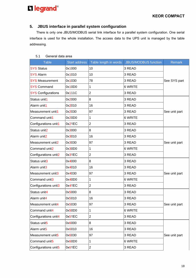
5. JBUS interface in parallel system configuration
There is only one JBUS/MODBUS serial link interface for a parallel system configuration. One serial
interface is used for the whole installation. The access data to the UPS unit is managed by the table
addressing.
5.1 General data area
Table Start address Table length in words JBUS/MODBUS function Remark
SYS Status 0x1000 10 3 READ
See SYS part
SYS Alarm 0x1010 10 3 READ
SYS Measurement 0x1030 78 3 READ
SYS Command 0x10D0 1 6 WRITE
SYS Configurations 0x111C 2 3 READ
Status unit1 0x2000 8 3 READ
See unit part
Alarm unit1 0x2010 16 3 READ
Measurement unit1 0x2030 97 3 READ
Command unit1 0x20D0 1 6 WRITE
Configurations unit1 0x21EC 2 3 READ
Status unit2 0x3000 8 3 READ
See unit part
Alarm unit2 0x3010 16 3 READ
Measurement unit2 0x3030 97 3 READ
Command unit2 0x30D0 1 6 WRITE
Configurations unit2 0x31EC 2 3 READ
Status unit3 0x4000 8 3 READ
See unit part
Alarm unit3 0x4010 16 3 READ
Measurement unit3 0x4030 97 3 READ
Command unit3 0x40D0 1 6 WRITE
Configurations unit3 0x41EC 2 3 READ
Status unit4 0x5000 8 3 READ
See unit part
Alarm unit4 0x5010 16 3 READ
Measurement unit4 0x5030 97 3 READ
Command unit4 0x50D0 1 6 WRITE
Configurations unit4 0x51EC 2 3 READ
Status unit5 0x6000 8 3 READ
See unit part
Alarm unit5 0x6010 16 3 READ
Measurement unit5 0x6030 97 3 READ
Command unit5 0x60D0 1 6 WRITE
Configurations unit5 0x61EC 2 3 READ

KEOR COMPACT
19
Status unit6 0x7000 8 3 READ
See unit part
Alarm unit6 0x7010 16 3 READ
Measurement unit6 0x7030 97 3 READ
Command unit6 0x70D0 1 6 WRITE
Configurations unit6 0x71EC 2 3 READ
5.2 SYS Status data area
STATUS : Address from 0x1000, 10 WORDS
Code Description BIT Address
S00 Rectifier Input Present OK 0 0x1000
S01 Bypass Input Present OK 1 0x1000
S02 Common Input 2 0x1000
S03 RESERVED 3 0x1000
S04 RESERVED 4 0x1000
S05 UPS in Normal Mode 5 0x1000
S06 RESERVED 6 0x1000
S07 UPS in ECO Mode 7 0x1000
S08 UPS in Converter Mode 8 0x1000
S09 RESERVED 9 0x1000
S10 RESERVED 10 0x1000
S11 RESERVED 11 0x1000
S12 RESERVED 12 0x1000
S13 RESERVED 13 0x1000
S14 Rectifier on 14 0x1000
S15 Inverter on 15 0x1000
S16 Battery Discharger on(1) 0 0x1001
S17 Battery Charger on(1) 1 0x1001
S18 RESERVED 2 0x1001
S19 RESERVED 3 0x1001
S20 RESERVED 4 0x1001
S21 Load off 5 0x1001
S22 Load on Inverter 6 0x1001
S23 Load on Bypass 7 0x1001
S24 Load on Manual Bypass 8 0x1001
S25 Permission for ECO Mode Bypass Supply 9 0x1001
S26 RESERVED 10 0x1001
S27 RESERVED 11 0x1001
S28 RESERVED 12 0x1001

KEOR COMPACT
20
S29 RESERVED 13 0x1001
S30 RESERVED 14 0x1001
S31 RESERVED 15 0x1001
S32 RESERVED 0 0x1002
S33 RESERVED 1 0x1002
S34 RESERVED 2 0x1002
S35 Redundancy operation 3 0x1002
S36 RESERVED 4 0x1002
S37 RESERVED 5 0x1002
S38 RESERVED 6 0x1002
S39 System is Common Battery 7 0x1002
S40 Vbatt. Ok(1) 8 0x1002
S41 Vbatt. Low(1) 9 0x1002
S42 Vbatt. Min(1) 10 0x1002
S43 ESS Discharging(1) 11 0x1002
S44 RESERVED 12 0x1002
S45 ESS Waiting for Process(1) 13 0x1002
S46 RESERVED 14 0x1002
S47 RESERVED 15 0x1002
S48 RESERVED 0 0x1003
S49 RESERVED 1 0x1003
S50 RESERVED 2 0x1003
S51 Permission for Close the Battery Switch(1) 3 0x1003
S52 RESERVED 4 0x1003
S53 RESERVED 5 0x1003
S54 RESERVED 6 0x1003
S55 RESERVED 7 0x1003
S56 RESERVED 8 0x1003
S57 RESERVED 9 0x1003
S58 RESERVED 10 0x1003
S59 RESERVED 11 0x1003
S60 RESERVED 12 0x1003
S61 Any one of Unit's buzzer is active 13 0x1003
S62 Remote Control Enabled 14 0x1003
S63 RESERVED 15 0x1003
S64 RESERVED 0 0x1004
S65 RESERVED 1 0x1004
S66 RESERVED 2 0x1004

KEOR COMPACT
21
S67 Manual Bypass Switch Closed 3 0x1004
S68 RESERVED 4 0x1004
S69 Output Switch Closed 5 0x1004
S70 RESERVED 6 0x1004
S71 Bypass SCR Activated 7 0x1004
S72 Battery Switch Closed 8 0x1004
S73 RESERVED 9 0x1004
S74 RESERVED 10 0x1004
S75 RESERVED 11 0x1004
S76 RESERVED 12 0x1004
S77 Output Contactor Closed 13 0x1004
S78 RESERVED 14 0x1004
S79 RESERVED 15 0x1004
S80 RESERVED 0 0x1005
S81 RESERVED 1 0x1005
S82 RESERVED 2 0x1005
S83 RESERVED 3 0x1005
S84 RESERVED 4 0x1005
S85 RESERVED 5 0x1005
S86 Unit 1 present 6 0x1005
S87 Unit 2 present 7 0x1005
S88 Unit 3 present 8 0x1005
S89 Unit 4 present 9 0x1005
S90 Unit 5 present 10 0x1005
S91 Unit 6 present 11 0x1005
S92 RESERVED 12 0x1005
S93 RESERVED 13 0x1005
S94 RESERVED 14 0x1005
S95 RESERVED 15 0x1005
S96 RESERVED 0 0x1006
S97 RESERVED 1 0x1006
S98 RESERVED 2 0x1006
S99 RESERVED 3 0x1006
S100 Unit 1 Operating 4 0x1006
S101 Unit 2 Operating 5 0x1006
S102 Unit 3 Operating 6 0x1006
S103 Unit 4 Operating 7 0x1006
S104 Unit 5 Operating 8 0x1006

KEOR COMPACT
22
S105 Unit 6 Operating 9 0x1006
S106 RESERVED 10 0x1006
S107 RESERVED 11 0x1006
S108 Comm. Board 1 Present 12 0x1006
S109 Comm. Board 2 Present 13 0x1006
S110 Comm. Board 3 Present 14 0x1006
S111 Comm. Board 4 Present 15 0x1006
S112 Comm. Board 5 Present 0 0x1007
S113 Comm. Board 6 Present 1 0x1007
S114 RESERVED 2 0x1007
S115 RESERVED 3 0x1007
S116 RESERVED 4 0x1007
S117 RESERVED 5 0x1007
S118 RESERVED 6 0x1007
S119 RESERVED 7 0x1007
S120 RESERVED 8 0x1007
S121 RESERVED 9 0x1007
S122 RESERVED 10 0x1007
S123 RESERVED 11 0x1007
S124 Schedule Condition Not Met 12 0x1007
S125 RESERVED 13 0x1007
S126 RESERVED 14 0x1007
S127 RESERVED 15 0x1007
S128 RESERVED 0 0x1008
S129 RESERVED 1 0x1008
S130 RESERVED 2 0x1008
S131 RESERVED 3 0x1008
S132 RESERVED 4 0x1008
S133 RESERVED 5 0x1008
S134 RESERVED 6 0x1008
S135 RESERVED 7 0x1008
S136 RESERVED 8 0x1008
S137 RESERVED 9 0x1008
S138 RESERVED 10 0x1008
S139 RESERVED 11 0x1008
S140 RESERVED 12 0x1008
S141 RESERVED 13 0x1008
S142 RESERVED 14 0x1008

KEOR COMPACT
23
S143 RESERVED 15 0x1008
S144 Schedule Battery Test Process Permitted(1) 0 0x1009
S145 Manual Battery Test Process Permitted(1) 1 0x1009
S146 After Battery Test, Battery is Aging(1) 2 0x1009
S147 After Battery Test, Battery Pass(1) 3 0x1009
S148 Battery Test Fail(1) 4 0x1009
S149 Battery Test in Progress(1) 5 0x1009
S150 Battery Test Condition Incompatible(1) 6 0x1009
S151 Waiting for The Battery Test Process 7 0x1009
S152 Manual Battery Test Time is Limited in 2
Minutes
8 0x1009
S153 RESERVED 9 0x1009
S154 RESERVED 10 0x1009
S155 RESERVED 11 0x1009
S156 Energy Saver Enable 12 0x1009
S157 Energy Saver On 13 0x1009
S158 Energy Saver is Operating 14 0x1009
S159 Any Unit has Standing by 15 0x1009
Note. Status with “RESERVED” are not usable in KEOR COMPACT Series protocol.
(1) Optional function for Common Battery.
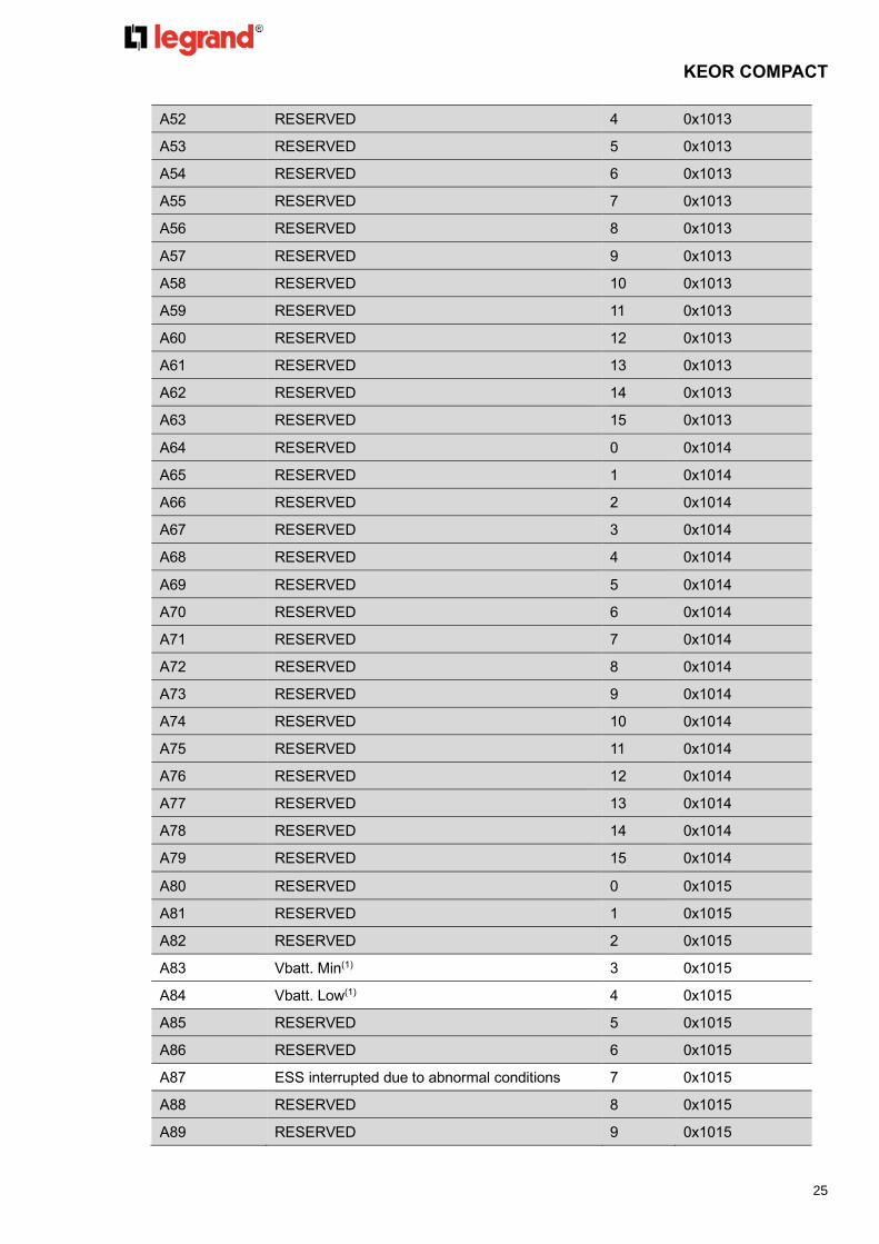
5.3 SYS Alarm data area
Alarms : Address from 0x1010, 16 WORDS
Code Description BIT Address
A00 RESERVED 0 0x1010
A01 Any Unit has General Alarm 1 0x1010
A02 Any Unit has Inverter General Alarm 2 0x1010
A03 Any Unit has Mains General Alarm 3 0x1010
A04 Any Unit has Discharger General Alarm 4 0x1010
A05 Any Unit has Charger General Alarm 5 0x1010
A06 Any Unit has Bypass General Alarm 6 0x1010
A07 RESERVED 7 0x1010
A08 RESERVED 8 0x1010
A09 RESERVED 9 0x1010
A10 Any Unit has Over Temp. 10 0x1010
A11 RESERVED 11 0x1010
A12 RESERVED 12 0x1010
A13 RESERVED 13 0x1010

KEOR COMPACT
24
A14 RESERVED 14 0x1010
A15 RESERVED 15 0x1010
A16 Unit 1 General Alarm 0 0x1011
A17 Unit 2 General Alarm 1 0x1011
A18 Unit 3 General Alarm 2 0x1011
A19 Unit 4 General Alarm 3 0x1011
A20 Unit 5 General Alarm 4 0x1011
A21 Unit 6 General Alarm 5 0x1011
A22 RESERVED 6 0x1011
A23 RESERVED 7 0x1011
A24 RESERVED 8 0x1011
A25 Any Unit has Inverter Fault 9 0x1011
A26 Any Unit has Rectifier Fault 10 0x1011
A27 RESERVED 11 0x1011
A28 RESERVED 12 0x1011
A29 Any Unit has Bypass SCR Fault 13 0x1011
A30 RESERVED 14 0x1011
A31 RESERVED 15 0x1011
A32 RESERVED 0 0x1012
A33 RESERVED 1 0x1012
A34 RESERVED 2 0x1012
A35 RESERVED 3 0x1012
A36 RESERVED 4 0x1012
A37 RESERVED 5 0x1012
A38 RESERVED 6 0x1012
A39 RESERVED 7 0x1012
A40 RESERVED 8 0x1012
A41 RESERVED 9 0x1012
A42 RESERVED 10 0x1012
A43 RESERVED 11 0x1012
A44 RESERVED 12 0x1012
A45 RESERVED 13 0x1012
A46 RESERVED 14 0x1012
A47 RESERVED 15 0x1012
A48 RESERVED 0 0x1013
A49 RESERVED 1 0x1013
A50 RESERVED 2 0x1013
A51 RESERVED 3 0x1013
KEOR COMPACT
25
A52 RESERVED 4 0x1013
A53 RESERVED 5 0x1013
A54 RESERVED 6 0x1013
A55 RESERVED 7 0x1013
A56 RESERVED 8 0x1013
A57 RESERVED 9 0x1013
A58 RESERVED 10 0x1013
A59 RESERVED 11 0x1013
A60 RESERVED 12 0x1013
A61 RESERVED 13 0x1013
A62 RESERVED 14 0x1013
A63 RESERVED 15 0x1013
A64 RESERVED 0 0x1014
A65 RESERVED 1 0x1014
A66 RESERVED 2 0x1014
A67 RESERVED 3 0x1014
A68 RESERVED 4 0x1014
A69 RESERVED 5 0x1014
A70 RESERVED 6 0x1014
A71 RESERVED 7 0x1014
A72 RESERVED 8 0x1014
A73 RESERVED 9 0x1014
A74 RESERVED 10 0x1014
A75 RESERVED 11 0x1014
A76 RESERVED 12 0x1014
A77 RESERVED 13 0x1014
A78 RESERVED 14 0x1014
A79 RESERVED 15 0x1014
A80 RESERVED 0 0x1015
A81 RESERVED 1 0x1015
A82 RESERVED 2 0x1015
A83 Vbatt. Min(1) 3 0x1015
A84 Vbatt. Low(1) 4 0x1015
A85 RESERVED 5 0x1015
A86 RESERVED 6 0x1015
A87 ESS interrupted due to abnormal conditions 7 0x1015
A88 RESERVED 8 0x1015
A89 RESERVED 9 0x1015

KEOR COMPACT
26
A90 Inverter Overload 10 0x1015
A91 Bypass Overload 11 0x1015
A92 UPS Overload Ohutdown 12 0x1015
A93 RESERVED 13 0x1015
A94 System Occurred Unpredictable Interrupt Output 14 0x1015
A95 Rectifier rating down to 50% 15 0x1015
A96 RESERVED 0 0x1016
A97 Output Switch Open 1 0x1016
A98 RESERVED 2 0x1016
A99 RESERVED 3 0x1016
A100 Manual Bypass Alarm 4 0x1016
A101 Battery Near End of Life 5 0x1016
A102 Any Unit has UPS Maintenance Alarm 6 0x1016
A103 RESERVED 7 0x1016
A104 RESERVED 8 0x1016
A105 RESERVED 9 0x1016
A106 RESERVED 10 0x1016
A107 RESERVED 11 0x1016
A108 RESERVED 12 0x1016
A109 RESERVED 13 0x1016
A110 RESERVED 14 0x1016
A111 RESERVED 15 0x1016
A112 RESERVED 0 0x1017
A113 RESERVED 1 0x1017
A114 RESERVED 2 0x1017
A115 RESERVED 3 0x1017
A116 RESERVED 4 0x1017
A117 Parallel Error - Parameter Setting 5 0x1017
A118 Parallel Error - System ID Conflict 6 0x1017
A119 Parallel Error - Communication Error 7 0x1017
A120 RESERVED 8 0x1017
A121 RESERVED 9 0x1017
A122 Parallel Error - Redundancy Loss 10 0x1017
A123 Parallel Error - Sync. Ring Disconnected 11 0x1017
A124 RESERVED 12 0x1017
A125 RESERVED 13 0x1017
A126 Parallel Error - Sync. Signal Failed 14 0x1017
A127 Parallel Error - System Number Setting 15 0x1017

KEOR COMPACT
27
A128 RESERVED 0 0x1017
A129 Parallel Error - Sync. of Start or Load Transfer
Error
1 0x1018
A130 RESERVED 2 0x1018
A131 RESERVED 3 0x1018
A132 EPO Activated 4 0x1018
A133 RESERVED 5 0x1018
A134 RESERVED 6 0x1018
A135 Comm. Board 1 Disconnected with Unit1 7 0x1018
A136 Comm. Board 2 Disconnected with Unit1 8 0x1018
A137 Comm. Board 3 Disconnected with Unit1 9 0x1018
A138 Comm. Board 4 Disconnected with Unit1 10 0x1018
A139 Comm. Board 5 Disconnected with Unit1 11 0x1018
A140 Comm. Board 6 Disconnected with Unit1 12 0x1018
A141 Comm. Board 1 CAN Error 13 0x1018
A142 Comm. Board 2 CAN Error 14 0x1018
A143 Comm. Board 3 CAN Error 15 0x1018
A144 Comm. Board 4 CAN Error 0 0x1019
A145 Comm. Board 5 CAN Error 1 0x1019
A146 Comm. Board 6 CAN Error 2 0x1019
A147 Comm. Board 1 General Alarm 3 0x1019
A148 Comm. Board 2 General Alarm 4 0x1019
A149 Comm. Board 3 General Alarm 5 0x1019
A150 Comm. Board 4 General Alarm 6 0x1019
A151 Comm. Board 5 General Alarm 7 0x1019
A152 Comm. Board 6 General Alarm 8 0x1019
A153 RESERVED 9 0x1019
A154 RESERVED 10 0x1019
A155 RESERVED 11 0x1019
A156 RESERVED 12 0x1019
A157 RESERVED 13 0x1019
A158 RESERVED 14 0x1019
A159 RESERVED 15 0x1019
A160~A239 RESERVED
A240 RESERVED 0 0x101F
A241 RESERVED 1 0x101F
A242 RESERVED 2 0x101F

KEOR COMPACT
28
A243 RESERVED 3 0x101F
A244 RESERVED 4 0x101F
A245 RESERVED 5 0x101F
A246 RESERVED 6 0x101F
A247 RESERVED 7 0x101F
A248 RESERVED 8 0x101F
A249 RESERVED 9 0x101F
A250~A255 RESERVED 10 0x101F
A251 RESERVED 11 0x101F
A252 RESERVED 12 0x101F
A253 RESERVED 13 0x101F
A254 RESERVED 14 0x101F
A255 RESERVED 15 0x101F
Note. Status with “RESERVED” are not usable in KEOR COMPACT Series protocol.
(1) Optional function for Common Battery.
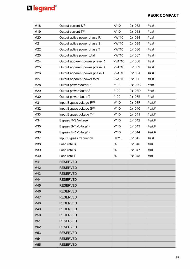
5.4 SYS Measurement data area
Information : Address from 0x1020, 121 WORDS
Code Description Unit Address Data Format
M00 Input voltage R(1)(3) V*10 0x1020 ###.#
M01 Input voltage S(1)(3) V*10 0x1021 ###.#
M02 Input voltage T(1)(3) V*10 0x1022 ###.#
M03 Input R-S Voltage(1)(3) V*10 0x1023 ###.#
M04 Input S-T Voltage(1)(3) V*10 0x1024 ###.#
M05 Input T-R Voltage(1)(3) V*10 0x1025 ###.#
M06 Input frequency Hz*10 0x1026 ##.#
M07 Input current R(1)(3) A*10 0x1027 ###.#
M08 Input current S(1)(3) A*10 0x1028 ###.#
M09 Input current T(1)(3) A*10 0x1029 ###.#
M10 Output voltage R(2) V*10 0x102A ###.#
M11 Output voltage S(2) V*10 0x102B ###.#
M12 Output voltage T(2) V*10 0x102C ###.#
M13 Output R-S Voltage(2) V*10 0x102D ###.#
M14 Output S-T Voltage(2) V*10 0x102E ###.#
M15 Output T-R Voltage(2) V*10 0x102F ###.#
M16 Output frequency Hz*10 0x1030 ##.#
M17 Output current R(2) A*10 0x1031 ##.#
KEOR COMPACT
29
M18 Output current S(2) A*10 0x1032 ##.#
M19 Output current T(2) A*10 0x1033 ##.#
M20 Output active power phase R kW*10 0x1034 ##.#
M21 Output active power phase S kW*10 0x1035 ##.#
M22 Output active power phase T kW*10 0x1036 ##.#
M23 Output active power total kW*10 0x1037 ##.#
M24 Output apparent power phase R kVA*10 0x1038 ##.#
M25 Output apparent power phase S kVA*10 0x1039 ##.#
M26 Output apparent power phase T kVA*10 0x103A ##.#
M27 Output apparent power total kVA*10 0x103B ##.#
M28 Output power factor R *100 0x103C #.##
M29 Output power factor S *100 0x103D #.##
M30 Output power factor T *100 0x103E #.##
M31 Input Bypass voltage R(1) V*10 0x103F ###.#
M32 Input Bypass voltage S(1) V*10 0x1040 ###.#
M33 Input Bypass voltage T(1) V*10 0x1041 ###.#
M34 Bypass R-S Voltage(1) V*10 0x1042 ###.#
M35 Bypass S-T Voltage(1) V*10 0x1043 ###.#
M36 Bypass T-R Voltage(1) V*10 0x1044 ###.#
M37 Input Bypass frequency Hz*10 0x1045 ##.#
M38 Load rate R % 0x1046 ###
M39 Load rate S % 0x1047 ###
M40 Load rate T % 0x1048 ###
M41 RESERVED
M42 RESERVED
M43 RESERVED
M44 RESERVED
M45 RESERVED
M46 RESERVED
M47 RESERVED
M48 RESERVED
M49 RESERVED
M50 RESERVED
M51 RESERVED
M52 RESERVED
M53 RESERVED
M54 RESERVED
M55 RESERVED

KEOR COMPACT
30
M56 RESERVED
M57 RESERVED
M58 RESERVED
M59 RESERVED
M60 RESERVED
M61 RESERVED
M62 RESERVED
M63 RESERVED
M64 Battery remaining capacity(4) %*10 0x1060 ##.#
M65 RESERVED
M66 Remaining run time(4) min 0x1062 ###
M67 Positive total battery voltage(4) V*100 0x1063 ###.##
M68 Negative total battery voltage(4) V*100 0x1064 ###.##
M69 Positive battery voltage per cell(4) V*100 0x1065 #.##
M70 Negative battery voltage per cell(4) V*100 0x1066 #.##
M71 Charging watt(4) kW*100 0x1067 ###.##
M72 Discharging watt(4) kW*100 0x1068 ###.##
M73 Positive battery charger current(4) A*100 0x1069 ###.##
M74 Negative battery charger current(4) A*100 0x106A ###.##
M75
Positive battery discharger
current(4) A*100 0x106B
###.##
M76 Negative battery discharger
current(4) A*100 0x106C ###.##
M77 RESERVED
M78 RESERVED
M79 RESERVED
M80 RESERVED
M81 RESERVED
M82 RESERVED
M83 RESERVED
M84 RESERVED
M85 RESERVED
M86 RESERVED
M87 RESERVED
M88 RESERVED
M89 RESERVED
M90 RESERVED
M91 RESERVED

KEOR COMPACT
31
M92 RESERVED
M93 Input Bypass current R(1) A*10 0x107D ###.#
M94 Input Bypass current S(1) A*10 0x107E ###.#
M95 Input Bypass current T(1) A*10 0x107F ###.#
M96 RESERVED
M97 RESERVED
M98 RESERVED
M99 RESERVED
M100 RESERVED
M101 RESERVED
M102 RESERVED
M103~M119 RESERVED
M120 Rectifier input active power kW*10 0x1098 ###.#
Note. Status with “RESERVED” are not usable in KEOR COMPACT Series protocol.
(1) This Information needs to be transferred if “Input transformer” is existing.
⚫ Displayed Mains Voltage = (Input Voltage * Input transformer ratio).
⚫ Displayed Mains Current = (Input current / Input transformer ratio).
⚫ Displayed Bypass Voltage = (Input Bypass Voltage * Input transformer ratio).
⚫ Displayed Bypass Current = (Input Bypass current / Input transformer ratio).
Note. “Input transformer ratio (T60)” settings please refers to chapter 5.6.
(2) This Information needs to be transferred if “Output transformer” is existing.
⚫ Displayed Output Voltage = (Output Voltage * Output transformer ratio).
⚫ Displayed Output Current = (Output current / Output transformer ratio).
Note. “Output transformer ratio (T61)” settings please refers to chapter 5.6.
(3) Optional function for Common input.
(4) Optional function for Common Battery.
5.5 SYS Control area
Following code must be written into 0x10D0 vector index address. The commands are coded by a
decimal value. Different value defined different command in word type.
Commands: Address: 0x10D0, 1word.
Code Description Remarks
C200 System Normal Mode
C202 System ECO Mode
C203 System Converter Mode
C205 System Shutdown Immediate load off!!
C206 System Load on Bypass
C214 System Buzzer Disable

KEOR COMPACT
32
C215 System Buzzer Enable
C216 System Clear Latch Alarm and Buzzer
5.6 SYS Configurations area Information : Address from 0x111C, 2 WORDS
Code Description Unit Address Remarks
T60 Input transformer ratio
parameter
N*100 0x111C 0 : No Transformer.
0~1 : Transformer ratio(1)
T61 Output transformer ratio
parameter
N*100 0x111D 0 : No Transformer.
0~1 : Transformer ratio(1)
(1) Transformer ratios can be calculated as following:
UPS
Input
TransformerOutput
Transformer
V1_in V2_in V1_out V2_out
Input transformer ratio = V1_in/V2_in = T60
Output transformer ratio = V2_out/V1_out = T61

KEOR COMPACT
33

KEOR COMPACT
34


